UH-1 -10 C20
134
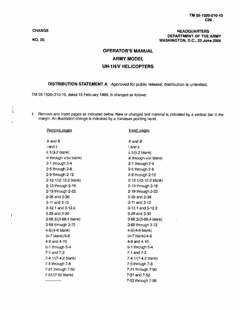
CHANGE NO. 20 OPERATOR'S MANUAL ARMY MODEL UH-1 H/V HELICOPTERS HEADQUARTERS DEPARTMENT OF THE ARMY WASHINGTON, D.C., 23 June 2005 DISTRIBUTION STATEMENT A: Approved for public release; distribution is unlimited. TM 55-1 520-21 0-10, dated 15 February 1988, is changed as follows: i 1. Remove and insert pages as indicated below. New or changed text material is indicated by a vertical bar in the margin. An illustration change is indicated by a miniature pointing hand. L Remove ~ a a e s Insert oaaes A and B i and ii ii. ll(ii.2 blank) iii through v/(vi blank) 2-1 through 2-4 2-5 through 2-8 2-9 through 2-12 2-12.142-12.2 blank) 2-13 through 2-16 2-19 through 2-22 2-35 and 2-36 3-11 and 3-12 3-1 2.1 and 3-1 2.2 3-29 and 3-30 3-68.3/(3-68.4 blank) 3-69 through 3-72 4-5/(4-6 blank) (4-7 blank)/4-8 4-9 and 4-10 5-1 through 5-4 7-1 and 7-2 7-4.1/(7-4.2 blank) 7-5 through 7-8 7-21 through 7-50 7-51/(7-52 blank) -------- A and B i and ii ii. ll(ii.2 blank) iii through v(vi blank) 2-1 through 2-4 2-5 through 2-8 2-9 through 2-12 2-12.1/(2-12.2 blank) 2-13 through 2-16 2-19 through 2-22 2-35 and 2-36 3-11 and 3-12 3-12.1 and 3-1 2.2 3-29 and 3-30 3-68.3/(3-68.4 blank) 3-69 through 3-72 4-5/(4-6 blank) (4-7 bIank)/4-8 4-9 and 4-1 0 5-1 through 5-4 7-1 and 7-2 7-4.1 /(7-4.2 blank) 7-5 through 7-8 7-21 through 7-50 7-51 and 7-52 7-53 through 7-56
-
Upload
clifford-mckeithan -
Category
Documents
-
view
233 -
download
16
Transcript of UH-1 -10 C20
CHANGE
NO. 20
OPERATOR'S MANUAL
ARMY MODEL
UH-1 H/V HELICOPTERS
HEADQUARTERS DEPARTMENT OF THE ARMY
WASHINGTON, D.C., 23 June 2005
DISTRIBUTION STATEMENT A: Approved for public release; distribution is unlimited.
TM 55-1 520-21 0-1 0, dated 15 February 1988, is changed as follows:
i 1. Remove and insert pages as indicated below. New or changed text material is indicated by a vertical bar in the margin. An illustration change is indicated by a miniature pointing hand.
L
Remove ~aaes Insert oaaes
A and B i and ii ii. ll(ii.2 blank) iii through v/(vi blank) 2-1 through 2-4 2-5 through 2-8 2-9 through 2-12 2-12.142-12.2 blank) 2-1 3 through 2-1 6 2-1 9 through 2-22 2-35 and 2-36 3-11 and 3-12 3-1 2.1 and 3-1 2.2 3-29 and 3-30 3-68.3/(3-68.4 blank) 3-69 through 3-72 4-5/(4-6 blank) (4-7 blank)/4-8 4-9 and 4-1 0 5-1 through 5-4 7-1 and 7-2 7-4.1/(7-4.2 blank) 7-5 through 7-8 7-21 through 7-50 7-51/(7-52 blank) --------
A and B i and ii ii. ll(ii.2 blank) iii through v(vi blank) 2-1 through 2-4 2-5 through 2-8 2-9 through 2-12 2-12.1/(2-12.2 blank) 2-13 through 2-16 2-19 through 2-22 2-35 and 2-36 3-11 and 3-12 3-1 2.1 and 3-1 2.2 3-29 and 3-30 3-68.3/(3-68.4 blank) 3-69 through 3-72 4-5/(4-6 blank) (4-7 bIank)/4-8 4-9 and 4-1 0 5-1 through 5-4 7-1 and 7-2 7-4.1 /(7-4.2 blank) 7-5 through 7-8 7-21 through 7-50 7-51 and 7-52 7-53 through 7-56

Remove Daaes 7.1-3 and 7.1-4 7.1 .-5 through 7.1-8 7.1-45 through 7.1-50 7.1-51 through 7.1 -53/(7.1-54 blank) 8-5 through 8-10 9-3 and 9-4 9-4.1/(9-4.2 blank)
9-5 and 9-6 9-8.1 /(9-8.2 blank) C-1 through C-5/(C-6 blank) lndex 1 through lndex 4
Insert Daaes 7.1-3 and 7.1-4 7.1 .-5 through 7.1-8 7.1-45 through 7.1-50 -------- 8-5 through 8-10 9-3 and 9-4 9-4.1 /(9-4.2 blank)
9-5 and 9-6 9-8.1/(9-8.2 blank) C- 1 /(C-2 blank) lndex 1 through lndex 4
2. Retain this sheet in front of manual for reference purposes.
By Order of the Secretary of the Army:
Official:
L 4 . a SANDRA R. RILEY /I
Administrative Assistant to the Secretary of the Army
050971 4
DISTRIBUTION:
PETER J. SCHOOMAKER General, United States Army
Chief of Staff
To be distributed in accordance with Initial Distribution Number (IDN) 310275, requirements for TM 55-1 520-21 0-10.

LIST OF EF FECTlVE PAGES
Insert latest changed pages . Dispose of superseded pages in accordance with regulations .
NOTE: On a changed page. the portion of the text affected by the latest change is indicated by a vertical line. in the outer margin of the page . Changes to illustrations are indicated by a miniature pointing hand .
DATES OF ISSUE FOR ORIGINAL AND CHANGED PAGES ARE:
Original . . . 0 . . . . . 15 February 1988 Change . . . 1 . . . . . 28 July 1988
Change . . . 2 . . . . . 17 October 1988
Change . . . 3 . . . . . 09 December 1988 . . . . . Change . . . 4 15 March 1989 . . . . . Change . . . 5 11 December 1989 . . . . . Change . . . 6 02 April 1990
Change . . . 7 . . . . . 17 December 1990 Change . . . 8 . . . . . 27 December 1990
. . . . . Change . . . 9 05 March 1991 . . . . . . . Change 10 18 April 1991
Change . . . 11 . . . . 01 July 1993
Change . . . 12 . . . . 23 July 1993
Change . . . 13 . . . . 30 November 1993 .
Change . . . 14 . . . . 09 March 1994
Change . . . 15 . . . . 14 February 1996
Change . . . 16 . . . . 13 August 1996
Change . . . 17 . . . . 13 February 1997
Change . . . 18 . . . . 08 October 1999
Change . . . 19 . . . . 31 December 2002
Change . . . 20 . . . . 23 June 2005
TOTAL NUMBER OF PAGES IN THIS PUBLICATION IS 254. CONSISTING OF THE FOLLOWING:
Page Number
*Change Number
Cover . . . . . . . . . . . . . . . . 0 A - B . . . . . . . . . . . . . . . . 20 i and ii . . . . . . . . . . . . . . . 20 ii . ll(ii.2 blank) . . . . . . . . 20
. . . . . iii thru v/(vi blank) 20 1-1 . . . . . . . . . . . . . . . . . . 18 1-2 . . . . . . . . . . . . . . . . . . . 8 2-1 . . . . . . . . . . . . . . . . . . . 0 2.2 . . . . . . . . . . . . . . . . . . 20 2.3 . . . . . . . . . . . . . . . . . . 20 2-4 and 2-5 . . . . . . . . . . 17 2-6 thru 2-1 3 . . . . . . . . . 20 2-14and2-15 . . . . . . . . 17 2-16 . . . . . . . . . . . . . . . . 20
. . . . . . 2.16.1 thru 2-19 17 2-20 thru 2-22 . . . . . . . . 20 2-23 and 2-24 . . . . . . . . 18 2-25 and 2-26 . . . . . . . . . 0
. . . . . 2.26.1/(26.2 blank) 7 . . . . . . . . . . . . . . . . . 2-27 7
2-28 . . . . . . . . . . . . . . . . . 0 2-29 . . . . . . . . . . . . . . . . 18 2-30 thru 2-33 . . . . . . . . . 0 2-34 . . . . . . . . . . . . . . . . 18 2-35 . . . . . . . . . . . . . . . . 20 2-36 . . . . . . . . . . . . . . . . . 0
Page *Change Number Number
2-37/(2-38 blank) . . . . . . 5 3-1 . . . . . . . . . . . . . . . . . . . 0 3-2 thru 3-11 . . . . . . . . . . 7 3-12 . . . . . . . . . . . . . . . . 20 3.12.1 . . . . . . . . . . . . . . . 17 3.12.2 . . . . . . . . . . . . . . . 20 3-13 thru 3-21 . . . . . . . . . 7 3-22 thru 3.22.28 . . . . . 18 3-23 thru 3-27 . . . . . . . . . 7 3-28 . . . . . . . . . . . . . . . . 17 3-29 . . . . . . . . . . . . . . . . 20 3-30 . . . . . . . . . . . . . . . . 17 3-31 . . . . . . . . . . . . . . . . . 7 3-32 thru 3.32.24 . . . . . 18 3-33 thru 3-36 . . . . . . . . . 7 3-37 and 3-38 . . . . . . . . 17 3-39 and 3-40 . . . . . . . . . 7 3-41 . . . . . . . . . . . . . . . . 17 3-42 . . . . . . . . . . . . . . . . 19 3-43 thru 3-67 . . . . . . . . . 7 3-68 thru 3.68.2 . . . . . . 16 3-68.3/(3-68.4 blank) . . 20 3-69 . . . . . . . . . . . . . . . . 20 3-70 . . . . . . . . . . . . . . . . 19 3-71 . . . . . . . . . . . . . . . . 20 3-72 thru 3-90 . . . . . . . . . 7
*Zero in this column indicates an original page .
Change 20 A

Page *Change Number Number
. . . . . . . . 4-5/(4-6 blank) 17 (4-7 blank) thru 4-10 . . 20 4-11 and4-12 . . . . . . . . . 5 4-13 . . . . . . . . . . . . . . . . . 0 4-14 . . . . . . . . . . . . . . . . 19 4-15 . . . . . . . . . . . . . . . . 14 4-16 . . . . . . . . . . . . . . . . . 0 5-1 . . . . . . . . . . . . . . . . . . 19 5-2 thru 5-4 . . . . . . . . . . 20 5-5 . . . . . . . . . . . . . . . . . . 15 5-6 . . . . . . . . . . . . . . . . . . 19 5-7 and 5-8 . . . . . . . . . . . 8 6-1 thru 6-4 . . . . . . . . . . 17 6-5 . . . . . . . . . . . . . . . . . . . 0 6.6 . . . . . . . . . . . . . . . . . . . 5
. . . . . . . . . . 6-7 thru 6-10 0 . . . . . . . . 6-11 thru 6-14 14
6-1 5 thru 6-20 . . . . . . . . . 0 7-1 . . . . . . . . . . . . . . . . . . 20 7-2 . . . . . . . . . . . . . . . . . . . 5 7-3 and 7-4 . . . . . . . . . . 17 7.4.1/(7.4.2 blank) . . . . 20 7-5 . . . . . . . . . . . . . . . . . . 17 7-6 and 7-7 . . . . . . . . . . 20 7-8 thru 7-13 . . . . . . . . . . 0 7-14 and 7-15 . . . . . . . . . 5 7-16 thru 7-47 . . . . . . . . . 0
. . . . . . . . . . . . . . . . 7-48 20 7-49 . . . . . . . . . . . . . . . . . 0 7-50 thru 7-56 . . . . . . . . 20 7.1.1 and 7.1.2 . . . . . . . . 8 7.1.3 . . . . . . . . . . . . . . . . 20
Page *Change Number Number
7.1.4 . . . . . . . . . . . . . . . . 17 7.1-4.1/(7.1-4.2 blank) . 19 7.1.5 . . . . . . . . . . . . . . . . 17
. . . . . . . . . . . . . . . . 7.1.6 20
. . . . . . . . . . . . . . . . 7.1.7 20 7.1.8thru7.1.45 . . . . . . . 8
. . . . . 7.1.46 and 7.1.47 20 7.1 -48 thru 7.1 -49 . . . . . . 8
. . . . . . . . . . . . . . . 7.1.50 20 . . . . . . . . . . 8-1 and 8-2 17 . . . . . . . . . . 8-3 and 8-4 16
. . . . . . . . . . . . . . . . . . 8.5 20 . . . . . . . . . . . . . . . . . 8-6 17
8-7 thru 8-10 . . . . . . . . . 20 . . . . . . 8.10.1 thru8-15 17
. . . . . . . . . . . . . . . . . 8-16 0 . . . . . . . . . . . . . . . . . . 9-1 15
9-2 . . . . . . . . . . . . . . . . . . 19 9.3 . . . . . . . . . . . . . . . . . . . 5 9.4 . . . . . . . . . . . . . . . . . . 20 9.4.1/(9.4.2 blank) . . . . 20 9.5 . . . . . . . . . . . . . . . . . . 20
. . . . . . . . . . 9-6 thru 9-8 17 . . . . 9.8.1/(9.8.2 blank) 20
9.9 . . . . . . . . . . . . . . . . . . . 8 . . . . . . . . . . . . . . . . . 9-10 0
9-11 thru 9-14 . . . . . . . . . 8 . . . . . . . A-1 /(A-2 blank) 17
. . . . . . . . . . . 8-1 and 8-2 0
. . . . . . . . . . 8-3 and 8-4 17 . . . . . . . C-1/(C-2 blank) 20
. . . Index 1 thru Index 4 20
*A zero in this column indicates an original page .
6 Change 20

TECHNICAL MANUAL 55-1 520-21 0-1 0
HEADQUARTERS DEPARTMENT OF THE ARMY
WASHINGTON D.C.,15 February 1988
OPERATOR'S MANUAL
ARMY MODEL UH-1 H/V HELICOPTER
REPORTING ERRORS AND RECOMMENDING IMPROVEMENTS
You can improve this manual . If you find any mistakes or if you know of a way to improve the procedures. please let us know . Mail your letter. DA Form 2028 (Recommended Changes to Publications and Blank Forms) located in the back of this manual directly to: Commander. U.S. Army Aviation and Missile Command. ATTN: AMSAM.MMC.MA.NP. Redstone Arsenal. AL 35898.5000 . A reply will be furnished to you . You may also provide DA Form 2028 information to AMCOM via e.mail. fax. or the World Wide Web . Our fax number is: DSN 788-6546 or Commercial 256.842.6546 . Our e-mail address is: [email protected]. Instructions for sending an electronic 2028 may be found at the back of this manual immediately preceding the hard copy 2028 . For the World Wide Web use: htt~s://amcom2028.redstone.armv.mil.
Distribution Statement A: Approved for public release; distribution is unlimited .
TABLE OF CONTENTS
CHAPTER 1 INTRODUCTION . . . . . . . . . . . . . . . . . . . . . . . . . . . . . . . . . . . . . . . . . . . CHAPTER 2
Section I . Section II . Section Ill . Section IV . Section V . Section VI . Section VII . Section VIII . Section IX . Section X . Section XI . Section XI1 . Section XIII . Section XIV .
CHAPTER 3 Section I . Section II . Section Ill . Section IV .
CHAPTER 4 Section I . Section II . Section Ill .
HELICOPTER AND SYSTEMS DESCRIPTION AND OPERATION . . . . . . . . . . . . . . . . . . . . . . . . . . . . . . . . . . . . . . . . . . . . . . . . . . . . . . . . . . . . . . . . . . . . . . . . . . . . Helicopter
Emergency Equipment . . . . . . . . . . . . . . . . . . . . . . . . . . . . . . . . . . . . . . . . . . . . . . . . . . . . Engine and Related Systems . . . . . . . . . . . . . . . . . . . . . . . . . . . . . . . . . . . . . . . . . . . . . . Helicopter Fuel System . . . . . . . . . . . . . . . . . . . . . . . . . . . . . . . . . . . . . . . . . . . . . . . . . . . . Flight Control System . . . . . . . . . . . . . . . . . . . . . . . . . . . . . . . . . . . . . . . . . . . . . . . . . . . . . Hydraulic System . . . . . . . . . . . . . . . . . . . . . . . . . . . . . . . . . . . . . . . . . . . . . . . . . . . . . . . . . Power Train System . . . . . . . . . . . . . . . . . . . . . . . . . . . . . . . . . . . . . . . . . . . . . . . . . . . . . .
. . . . . . . . . . . . . . . . . . . . . . . . . . . . . . . . . . . . . . . . . . . . . . . . . . . . . . . . . . . . . . . . . . Rotors Utility Systems . . . . . . . . . . . . . . . . . . . . . . . . . . . . . . . . . . . . . . . . . . . . . . . . . . . . . . . . . . . Heating and Ventilation . . . . . . . . . . . . . . . . . . . . . . . . . . . . . . . . . . . . . . . . . . . . . . . . . . . . Electrical Power Supply and Distribution System . . . . . . . . . . . . . . . . . . . . . . . . . . . . . .
. . . . . . . . . . . . . . . . . . . . . . . . . . . . . . . . . . . . . . . . . . . . . . . . . . . . . . . . . . . . . . . . . Lighting Flight Instruments . . . . . . . . . . . . . . . . . . . . . . . . . . . . . . . . . . . . . . . . . . . . . . . . . . . . . . . . Servicing Parking and Mooring . . . . . . . . . . . . . . . . . . . . . . . . . . . . . . . . . . . . . . . . . . . . .
. . . . . . . . . . . . . . . . . . . . . . . . . . . . . . . . . . . . . . . . . . . . . . . . . . . . . . . . . . . . . . . AVIONICS . . . . . . . . . . . . . . . . . . . . . . . . . . . . . . . . . . . . . . . . . . . . . . . . . . . . . . . . . . . . . . . . . General
Communication . . . . . . . . . . . . . . . . . . . . . . . . . . . . . . . . . . . . . . . . . . . . . . . . . . . . . . . . . . . . . . . . . . . . . . . . . . . . . . . . . . . . . . . . . . . . . . . . . . . . . . . . . . . . . . . . . . . . . . . . . Navigation
Transponder and Radar . . . . . . . . . . . . . . . . . . . . . . . . . . . . . . . . . . . . . . . . . . . . . . . . . . . MISSION EQUIPMENT . . . . . . . . . . . . . . . . . . . . . . . . . . . . . . . . . . . . . . . . . . . . . . . . . . . Armament . . . . . . . . . . . . . . . . . . . . . . . . . . . . . . . . . . . . . . . . . . . . . . . . . . . . . . . . . . . . . . . Mission Avionics . . . . . . . . . . . . . . . . . . . . . . . . . . . . . . . . . . . . . . . . . . . . . . . . . . . . . . . . .
. . . . . . . . . . . . . . . . . . . . . . . . . . . . . . . . . . . . . . . . . . . . . . . . . . . . . . . . . . Cargo Handling
Page 1-1

CHAPTER 5 Section I . Section I1 . Section Ill . Section IV . Section V . Section VI . Section VII . Section VI I I . Section IX . Section X .
CHAPTER 6 Section I . Section I1 . Section Ill . Section IV . Section V . Section VI . Section VII .
CHAPTER 7 Section I . Section I1 . Section Ill . Section IV . Section V . Section VI . Section VII . I Section VIII .
CHAPTER 7.1 Section I . Section II . Section Ill . Section IV . Section V . Section VI . Section VII . 1 Section V~t l .
CHAPTER 8 Section I . Section I1 . Section Ill . Section IV . Section V . Section VI .
CHAPTER 9 Section I .
TABLE OF CONTENTS (CONT)
. . . . . . . . . . . . . . . . . . . . . . . . . . . . . . . . . OPERATING LIMITS AND RESTRICTIONS . . . . . . . . . . . . . . . . . . . . . . . . . . . . . . . . . . . . . . . . . . . . . . . . . . . . . . . . . . . . . . . . . General
. . . . . . . . . . . . . . . . . . . . . . . . . . . . . . . . . . . . . . . . . . . . . . . . . . . . . . . . . . . . System Limits . . . . . . . . . . . . . . . . . . . . . . . . . . . . . . . . . . . . . . . . . . . . . . . . . . . . . Power Limits . . . . . . .
. . . . . . . . . . . . . . . . . . . . . . . . . . . . . . . . . . . . . . . . . . . . . . . . . . . . . . . . . . . Loading Limits
. . . . . . . . . . . . . . . . . . . . . . . . . . . . . . . . . . . . . . . . . . . . . . . . . . . . . . . . . . . Airspeed Limits Maneuvering Limits . . . . . . . . . . . . . . . . . . . . . . . . . . . . . . . . . . . . . . . . . . . . . . . . . . . . . . .
.................................................. Environmental Restrictions . . . . . . . . . . . . . . . . . . . . . . . . . . . . . . . . . . . . . . . . . . . . . . . . . . . . . . . . . . . Height Velocity
. . . . . . . . . . . . . . . . . . . . . . . . . . . . . . . . . . . . . . . . Internal Rescue Hoist (Breeze Only) . . . . . . . . . . . . . . . . . . . . . . . . . . . . . . . . . . . . . . . . . . . . . . . . . . . . . . . . . Other Limitations
. . . . . . . . . . . . . . . . . . . . . . . . . . . . . . . . . . . . . . . . WEIGHTIBALANCE AND LOADING . . . . . . . . . . . . . . . . . . . . . . . . . . . . . . . . . . . . . . . . . . . . . . . . . . . . . . . . . . . . . . . . . General
. . . . . . . . . . . . . . . . . . . . . . . . . . . . . . . . . . . . . . . . . . . . . . . . . . . . . . Weight and Balance . . . . . . . . . . . . . . . . . . . . . . . . . . . . . . . . . . . . . . . . . . . . . . . . . . . . . . . . . . . . . . . . . FuelIOil
. . . . . . . . . . . . . . . . . . . . . . . . . . . . . . . . . . . . . . . . . . . . . . . . . . . . . . . . . . . . . . . Personnel . . . . . . . . . . . . . . . . . . . . . . . . . . . . . . . . . . . . . . . . . . . . . . . . . . . . . . . Mission Equipment
. . . . . . . . . . . . . . . . . . . . . . . . . . . . . . . . . . . . . . . . . . . . . . . . . . . . . . . . . . . Cargo Loading . . . . . . . . . . . . . . . . . . . . . . . . . . . . . . . . . . . . . . . . . . . . . . . . . . . Center of Gravity Limits . . . . . . . . . . . . . . . . . . . . . . . . . . . . . . . . . . . . . . . . . . . . . . . . . . . PERFORMANCE DATA
. . . . . . . . . . . . . . . . . . . . . . . . . . . . . . . . . . . . . . . . . . . . . . . . . . . . . . . . . . . . . . lntroduction . . . . . . . . . . . . . . . . . . . . . . . . . . . . . . . . . . . . . . . . . . . . . . . . . . . . . . . . . Torque Available
. . . . . . . . . . . . . . . . . . . . . . . . . . . . . . . . . . . . . . . . . . . . . . . . . . . . . . . . . . . . . . . . . . . Hover Takeoff . . . . . . . . . . . . . . . . . . . . . . . . . . . . . . . . . . . . . . . . . . . . . . . . . . . . . . . . . . . . . . . . . .
. . . . . . . . . . . . . . . . . . . . . . . . . . . . . . . . . . . . . . . . . . . . . . . . . . . . . . . . . . . . . . . . . . Cruise . . . . . . . . . . . . . . . . . . . . . . . . . . . . . . . . . . . . . . . . . . . . . . . . . . . . . . . . . . . . . . . . . . . . Drag
Climb-Descent . . . . . . . . . . . . . . . . . . . . . . . . . . . . . . . . . . . . . . . . . . . . . . . . . . . . . . . . . . . . . . . . . . . . . . . . . . . . . . . . . . . . . . . . . . . . . . . . . . . . . . . . . . . . . . . . . . . . . . . . . . . Fuel Flow
. . . . . . . . . . . . . . . . . . . . . . . . . . . . . . . . . . . . . . . . . . . . . . . . . . . PERFORMANCE DATA . . . . . . . . . . . . . . . . . . . . . . . . . . . . . . . . . . . . . . . . . . . . . . . . . . . . . . . . . . . . . . lntroduction
TorqueAvailable . . . . . . . . . . . . . . . . . . . . . . . . . . . . . . . . . . . . . . . . . . . . . . . . . . . . . . . . . . . . . . . . . . . . . . . . . . . . . . . . . . . . . . . . . . . . . . . . . . . . . . . . . . . . . . . . . . . . . . . . . . . . Hover
Takeoff . . . . . . . . . . . . . . . . . . . . . . . . . . . . . . . . . . . . . . . . . . . . . . . . . . . . . . . . . . . . . . . . . . . . . . . . . . . . . . . . . . . . . . . . . . . . . . . . . . . . . . . . . . . . . . . . . . . . . . . . . . . . . . . . . . . . Cruise
. . . . . . . . . . . . . . . . . . . . . . . . . . . . . . . . . . . . . . . . . . . . . . . . . . . . . . . . . . . . . . . . . . . . Drag . . . . . . . . . . . . . . . . . . . . . . . . . . . . . . . . . . . . . . . . . . . . . . . . . . . . . . . . . . . Climb-Descent
. . . . . . . . . . . . . . . . . . . . . . . . . . . . . . . . . . . . . . . . . . . . . . . . . . . . . . . . . . . . . . . . Fuel Flow . . . . . . . . . . . . . . . . . . . . . . . . . . . . . . . . . . . . . . . . . . . . . . . . . NORMAL PROCEDURES
. . . . . . . . . . . . . . . . . . . . . . . . . . . . . . . . . . . . . . . . . . . . . . . . . . . . . . . . . Mission Planning . . . . . . . . . . . . . . . . . . . . . . . . . . . . . . . . . . . . . . . . . . . . . . . . . . . . . . . . . . . . . Crew Duties
Operating Procedues and Maneuvers . . . . . . . . . . . . . . . . . . . . . . . . . . . . . . . . . . . . . . . . . . . . . . . . . . . . . . . . . . . . . . . . . . . . . . . . . . . . . . . . . . . . . . . . . . . . . . . . Instrument Flight
. . . . . . . . . . . . . . . . . . . . . . . . . . . . . . . . . . . . . . . . . . . . . . . . . . . . . . Flight Characteristics Adverse Environmental Conditions . . . . . . . . . . . . . . . . . . . . . . . . . . . . . . . . . . . . . . . . . . EMERGENCY PROCEDURES . . . . . . . . . . . . . . . . . . . . . . . . . . . . . . . . . . . . . . . . . . . . .
. . . . . . . . . . . . . . . . . . . . . . . . . . . . . . . . . . . . . . . . . . . . . . . . . . . . . . . Helicopter Systems
Page 5-1 5-1 5-1 5-1 5-2 5-2 5-2 5-3 5-3 5-3 5-3
6-1 6-1 6-1 6-2 6-2 6-2 6-3 6-4
7-1 7-1 7-3 7-4 7-4 7-5 7-6
Deleted Deleted
7.1-1 7.1-1 7.1-3 7.1-4 7.1-4 7.1-5 7.1-6
Deleted Deleted
8-1 8-1 8-1 8-1 8-9 8-9
8-11
9-1 9-1
ii Change 20

TABLE OF CONTEIJTS (CONT) APPENDIX A REFERENCES . . . . . . . . . . . . . . . . . . . . . . . . . . . . . . . . . . . . . . . . . . . . . . . . . . . . . . . . . . . . . . . . . . A-1
B ABBREVIATIONS AND TERMS . . . . . . . . . . . . . . . . . . . . . . . . . . . . . . . . . . . . . . . . . . . . . . . . . . . B-1
C TABULAR PERFORMANCE DATA IJIOVED TO CHAPTER 7 . . . . . . . . . . . . . . . . . . Deleted INDEX . . . . . . . . . . . . . . . . . . . . . . . . . . . . . . . . . . . . . . . . . . . . . . . . . . . . . . . . . . . . . . . . . . . . . . . . . . INDEX-1
Change 20 ii.1 I(ii.2 blank)
-


LIST OF ILLUSTRATIONS (CONT)
Figure Title Page
. . . . . . . . . . . . . . . . . . . . . . . . . . . . . . . . . . . . . . . . . . . . . . . Hoist Loading Limitations (Lateral CG) 6-9 . . . . . . . . . . . . . . . . . . . . . . . . . . . . . . . . . . . . . . . . . . Hoist Loading Limitations (Longitudinal CG)) 6-10
. . . . . . . . . . . . . . . . . . . . . . . . . . . . . . . . . . . . . . . . . . . . . . System Weight and Balance Data Sheet 6-11 . . . . . . . . . . . . . . . . . . . . . . . . . . . . . . . . . . . . . . . . . . . . . . . . . . . . . . . . . . Hoist Installation Positions 6-14
. . . . . . . . . . . . . . . . . . . . . . . . . . . . . . . . . . . . . . . . . . . . . . . . . . . . . . . . . . . . . . . Cargo Compartment 6-15 . . . . . . . . . . . . . . . . . . . . . . . . . . . . . . . . . . . . . . . . . . . . . . . . . . . . . . . . . Cargo Tiedown Fitting Data 6-16
. . . . . . . . . . . . . . . . . . . . . . . . . . . . . . . . . . . . . . . . . . . . . . . . . . Internal Cargo Weight and Moment 6-17 . . . . . . . . . . . . . . . . . . . . . . . . . . . . . . . . . . . . . . . . . . . . . . . . . External Cargo Weight and Moment 6-18
. . . . . . . . . . . . . . . . . . . . . . . . . . . . . . . . . . . . . . . . . . . . . . . . . . . . . . . . . . . . Center of Gravity Limits 6-19 . . . . . . . . . . . . . . . . . . . . . . . . . . . . . . . . . . . . . . . . . . . . . . . . . rn Temperature Conversion Chart 7-12
. . . . . . . . . . . . . . . . . . . . . . . . . . . Maximum Torque Available (30 Minute Operation) Chart 7-13
. . . . . . . . . . . . . . . . . . . . . . . . . . . . . . . . . . . . . . . . . . . . . . . . . rn Hover (Power Required) Chart 7-14
. . . . . . . . . . . . . . . . . . . . . . . . . . . . . . . . . . . . . . . . . . . . . . . . . . . . . . . . . . . . . . . . rn Control Margin 7-16 . . . . . . . . . . . . . . . . . . . . . . . . . . . . . . . . . . . . . . . . . . . . . . . . . . . . . . . . . . . . . . . . . rn Takeoff Chart 7-18
. . . . . . . . . . . . . . . . . . . . . . . . . . . . . . . . . . . . . . . . . . . . . . . . . . . . . . . . . . . . . . . . . . rn Cruise Chart 7-21 . . . . . . . . . . . . . . . . . . . . . . . . . . . . . . . . . . . . . . . . . . . . . . . . . . . . . . . . . . . . . . . . . . . Drag Chart 7-48
. . . . . . . . . . . . . . . . . . . . . . . . . . . . . . . . . . . . . . . . . . . . . . . . . . . . . . . . . . rn Climb-Descent Chart Deleted . . . . . . . . . . . . . . . . . . . . . . . . . . . . . . . . . . . . . . . . . . . . . . . . . . . . . . . . . . . rn Idle Fuel Flow Chart Deleted
. . . . . . . . . . . . . . . . . . . . . . . . . . . . . . . . . . . . . . . . . . . . . . . . . rn Temperature Conversion Chart 7.1.8
rn Danger Area Maximum Torque (30 Minute Operation) Chart 7.1.9
I .. . . . . . . . . . . . . . . . . . . . . . .
. . . . . . . . . . . . . . . . . . . . . . . . . . . . . . . . . . . . . . . . . . . . . . . . . . . . . . . . . . . . . . . . . . rn Hover Chart 7.1.1 1
. . . . . . . . . . . . . . . . . . . . . . . . . . . . . . . . . . . . . . . . . . . . . . . . . . . . . . . . . . Control Margin Chart 7.1.1 5
. . . . . . . . . . . . . . . . . . . . . . . . . . . . . . . . . . . . . . . . . . . . . . . . . . . . . . . . . . rn Control Margin Chart 7.1.1 7
. . . . . . . . . . . . . . . . . . . . . . . . . . . . . . . . . . . . . . . . . . . . . . . . . . . . . . . . . . . . . . . . . rn Cruise Chart 7.1.20
. . . . . . . . . . . . . . . . . . . . . . . . . . . . . . . . . . . . . . . . . . . . . . . . . . . . . . . . . . . . . . . . . . . Drag Chart 7.1.46
. . . . . . . . . . . . . . . . . . . . . . . . . . . . . . . . . . . . . . . . . . . . . . . . . . . . . . . . . . . . . . . . . . rn Climb Chart Deleted
. . . . . . . . . . . . . . . . . . . . . . . . . . . . . . . . . . . . . . . . . . . . . . . . . . . . . . . . . . . . . . Fuel Flow Chart Deleted . . . . . . . . . . . . . . . . . . . . . . . . . . . . . . . . . . . . . . . . . . . . . . . . . . . . . . . . . . . . . . . . . . . . . . Danger Area 8-15
. . . . . . . . . . . . . . . . . . . . . . . . . . . . . . . . . . . . . . . . . . . . . . . . . . . . . . . . . . . . Exterior Check Diagram 8-16 . . . . . . . . . . . . . . . . . . . . . . . . . . . . . . . . . . . . . . . . . . . . . . . . . . . . Emergency Exits and Equipment 9-10
rn Autorotational Glide Characteristics Chart 9-11
I ... . . . . . . . . . . . . . . . . . . . . . . . . . . . . . . . . . . . . . . . . . . . . . . . . . . . . . . . . . . . . . . . . . . . . . . . . . . . rn Autorotational Glide Characteristics Chart 9-12
. . . . . . . . . . . . . . . . . . . . . . . . . . . . . . . . . . . . . . . . . . . . . . . . . . . . . . . rn Height Velocity Diagram 9-13
. . . . . . . . . . . . . . . . . . . . . . . . . . . . . . . . . . . . . . . . . . . . . . . . . . . . . . . rn Height Velocity Diagram 9-14
Change 20 v/(vi blank)


CHAPTER 2 HELICOPTER AND SYSTEMS DESCRIPTION AND OPERATION
SECTION I. HELICOPTER
2-1. General Description. The UH-1 HN helicopters b. Tail Skid. A tubular steel tail skid is installed on are thirteen-place single engine helicopters. The maxi- the aft end of the tailboom. It acts as a warning to the pilot mum gross weight is 9500 pounds. upon an inadvertent tail-low landing and aids in protect-
ing the tail rotor from damage. 2-2. General Arrangement. Figure 2-1 depicts the general arrangement Indexed items include access 2-8m crew compartment ~ i ~ ~ ~ ~ ~ . T~~ crew cornpart- openings and most of the items referred to in the exterior is depicted in figure 2-5. check paragraph in section Ill of chapter 8.
2-3. Principal Dimensions. Figure 2-2 depicts the 2-9- Cockpit and Cabin Doors. principal dimensions. a. Cockpit Doors. The cock~it doors are formed
aluminum frames with transparent plastic windows in the 2-4. Turning Radius' Turning radius is about 35 feet upper (fig 2-1). Ventilation is supplied by the slid- when pivoted around the mast. ina ~anels in the windows. Cam-tv~e door latches are
2-5. Fuselage. ~h~ fuselage is the forward section of uied and doors are equipped witiiettisonable door re- the airframe extendina from the nose to the forward end leases. of the tailboom. The ;uselage consists primarily of two longitudinal beams with transverse bulkheads and metal covering. The main beams are the supporting structure for the cabin, landing gear, fuel tanks, transmission, en- gine, and tailboom. The external cargo suspension unit is attached to the main beams near the center of gravity of the helicopter.
2-6. Tailboom. The tailboom section is bolted to the aft end of the fuselage and extends to the aft end of the helicopter. It is a tapered, semi-monocoque structure comprised of skins, longerons, and stringers. The tail- boom supports the tail rotor, vertical fin, and synchro- nized elevator. It houses the tail rotor driveshaft and some electronic equipment.
b. Cabin Doors. The two cabin doors are formed aluminum frames with transparent plastic windows in the upper section (fig 2-1). These doors are on rollers and slide aft to the open position allowing full access to the cargo area. Hinged doorpost panels are forward of the cabin doors. They provide a larger entrance to the cargo area. An oDen door lock is ~rovided to hold the door in the aft positio;l to prevent door separation in flight.
2-10. PllotlCopilot Seats. The pilot and copilot seats may be conventional seats or armored seats (fig 2-3). The armored seats have a release to recline the seats to aid in removal of injured personnel. The conventional seats do not have the reclining feature.
2-7. Landing Gear System. a. Pilot and Copilot Seats (Conventional). The pi- lot and copilot seats are vertical and fore-aft adjustable
a. Main Landing Gear. The main landing gear and the nonreclining type. The vertical height adjustment consists of two aluminum arched crosstubes mounted handle is under the right side of the seat. The fore and aft laterally on the fuselage with two longitudinal skid tubes adjustment is under the left side of the seat. Webbing on attached to the crosstubes. The skid tubes are made of the back of the seat can be removed to accept use of a aluminum and have steel skid shoes attached to the back-pack parachute. The seats are equipped with lap bottom to minimize skid wear. safety belts and inertia reel shoulder harness.

b. Pilot and Copilot Seats (Armored). Armored I seats can be installed in the helicopter for the pilot and
cop~lot. They are equipped with lap safety belt and iner- tia-reel shoulder harness. They are adjustable fore and aft and vertically. The vertical adjustment handle is under the right side of the seat and the fore and aft handle on the left. The seats are equipped with a quick release, on each side at the back of the seat, for reclining the seat. The seat back, bottom, and sides are protected by ce- ramic and aluminum armor plate. Hip and shoulder areas are protected by ceramic type armor.
c. Inertia Reel Shoulder Harness. An inertia reel and shoulder harness is incorporated in the pilot and copilot seats with manual lock-unlock handle (fig 2-3). On the conventional seat, the control handles are located on the left front of the seat. On the armored seat, the control handles are located on the right front of the seat. With the control in the unlocked position (aft) and the shoulder straps properly adjusted, the reel strap will extend to allow the occupant to lean forward; however, the reel automatically locks when the helicopter encounters an impact force of 2 to 3 "G" deceleration. The reel can be locked (handle forward) from any position and will take up slack in the harness. To release the lock, it is neces- sary to lean back slightly to release tension on the lock and move the control handle to the unlock position. It is possible to have pressure against the seat back whereby no additional movement is possible and the lock cannot be released. If this condition occurs, it will be necessary to loosen the harness. The reel should be manually locked for emergency landing. Straps must be adjusted to fully retract within the inertia reels to prevent rebound overshoot in the event of impact. Seat belt must be se- curely fastened and firmly tightened prior to adjustment of shoulder harness to prevent submarining in event of impact.
2-1 1. Personnel Seats. Various arrangements of per- sonnel seats can be installed to accommodate from one to eleven personnel besides the pilot and copilot. The
seatsare constructed of tubular steel and reinforced can- vas. Each seat is equipped with a lap safety belt. For additional information on the personnel seats, refer to chapter 6. Patients will be secured to litters utilizing the approved patient securing straps when the helicopter is used for medical evacuation missions. I 2-1 2. Instruments and Controls.
a. Instrument Panel. The location of all the con- trols, indicators, instruments, and data placards installed on the instrument panel is depicted in figure 2-4 V. Some I instruments may be relocated.
b. Pedestal Panel. The panels and controls installed in the pedestal are depicted in figure 2-5.
c. Overhead Console. The location of the controls and circuit breakers installed in the overhead console is depicted in figure 2-5.
d. External Stores Jettison Handle. The external stores Jettison handle is located to the left of the pilot collective when installed. Pulling up on the handle will Jettison external stores through mechanical linkage.
e. Other lnstruments and Controls. Instruments, controls, or indicators not shown in figure 2-5 or figure 2-6 are shown in the chapterlsection which describes their related systems.
2-12.1 Wire Strike Protection System (WSPS). The I WSPS provides protection for 90% of the frontal area against impacts with horizontally strung mechanical and power transmission cables. The basic system consists of an upper cutterldeflector, a windshield protectorldeflec- torlcutter, a lower cutterldeflector and a pair of windshield wiper deflectors (fig 2-1). The lower cutter assemblyfea- tures a "Breakaway Tip" designed to shear when relative- ly large ground contact forces are experienced and be- fore helicopter structural damage is incurred. However, the tip shear rivets are designed to withstand the smaller forces experienced during wire strikes and the tip will still effectively deflect wireslcables into the cutter blades.
2-2 Change 20

SECTION II. EMERGENCY EQUIPMENT
2-13. Emergency Equipment. The emergency equip- of the pedestal, or to the right of the pilot seat. ment location, illustration, and emergency procedures are covered in chapter 9. 2-1 5. First Aid Kits. Four general purpose type first aid
kits have been provided in the cabin area (fig 9-1). Two kits are secured to the right center doorpost. The other
2-14. Portable Fire Extinguisher. A portable hand-op- two kits are secured to the left doorpost. First aid kits can erated fire extinguisher is carried in a bracket located aft be easily removed for immediate use.
SECTION Ill. ENGINE AND RELATED SYSTEMS
2-16. Engine. The UH-1HN are equipped with a T53-L-13 engine.
2-17. Engine Compartment Cooling. The engine compartment is cooled by natural convection through engine compartment screens.
2-18. Air Induction System. Three different air induc- tion systems are used on these helicopters. They are discussed in the following paragraphs:
1 a. Deleted.
b. Self-purging Particle Separator. Helicopters serial No. 68-15779 and subsequent are equipped with a self-purging particle separator. This is an inertial-type separator. Particle-laden air is directed through a large annular chamber and through an air cleaner. A constant supply of bleed air from the engine flows through the
I venture-type ejector and carries particles overboard through airframe plumbing. Some self-purging particle separator systems have operational ENGINE INLET AIR caution panel segment lights.
c. Foreign Object Damage Screen. Foreign Ob- ject Damage (FOD) screen prevents large particles from entering the engine inlet.
NOTE The ice detector system is not applicable on helicopters equipped with the self-purging particle separator.
d. DE-ICE. Engine de-ice is a bleed air system activated by the DE-ICE switch on the ENGINE panel (fig 2-6). In the ON position bleed air is directed through the engine inlet to provide the protection. Power losses caused when the system is on are shown in chapter 7. In the event of dc electrical failure or when the DE-ICE ENG circuit breaker is out de-ice is automatically on. System power is provided by the dc essential bus and protected by the ANTI-ICE ENG circuit breaker.
e. Improved Particle Separator. Some UH-1's may be equipped with an improved particle separator. This unit has a number of vortex tubes which are highly I effective in removing sand and dust from the engine inlet air. The sand and dust are dumped overboard through outlets on each side of the Separator are highly effective in removing sand and dust from the engine inlet air. The sand and dust are dumped overboard through outlets on each side of the Separator.
2-1 9. Engine Fuel Control System.
a. Engine Mounted Components. The fuel control assembly is mounted on the engine. It consists of a me- tering section a computer section and an overspeed gov- ernor.
(1) The metering section is driven at a speed proportional to N1 speed. It pumps fuel to the engine through the main metering valve or if the main system falls through the emergency metering valve which is positioned directly by the twist grip throttle.

(2) The computer section determines the rate of main fuel delivery by biasing main metering valve opening for N1 speed, inlet air temperature and pres- sure, and throttle position. It also controls the operation of the compressor air bleed and operation of the variable inlet guide vanes.
(3) The overspeed governor is driven at a speed proportional to N2 speed. It biases the main me- tering valve opening to maintain a constant selected N2 rpm.
b. Starting Fuel Flow During engine start, ener- gizing the start fuel switch opens the fuel solenoid valve, allowing fuel from the fuel regulator to flow through the starting fuel manifold and into the combustion chamber. When N1 reaches sufficient speed, the start switch is de-energized, causing the solenoid valve to close and stop-starting fuel flow. Starting fuel nozzles are purged by air from the combustion chamber through a check falter valve. Engine starting fuel solenoid valve is con- trolled by the engine starter switch on helicopters which do not have a starting fuel switch. The engine solenoid valve (engine starting fuel solenoid valve) cannot be indi- vidually controlled during engine starts.
c. Power Controls (Throtfles). Rotating the pilot or copilot twist grip-type throttle (fig 2-5) to the full open position allows the overspeed governor to maintain a constant rpm. Rotating the throttle toward the closed position will cause the rpm to be manually selected instead of automaticallv selected bv the overspeed oov- ernor. Rotating the throttle to the-fully closed position shuts off the fuel. An idle stop is incorporated in the throttle to prevent inadvertent throttle closure. To bypass the idle detent press the IDLE REL switch and close the throttle. The IDLE REL switch is a momentary on, sole- noid-operated switch. The IDLE REL switch is located on the pilot collective stick switch box. IDLE REL switch receives power from the 28 Vdc bus and is protected by a circuit breaker marked IDLE STOP REL. Friction can be induced in both throttles by rotating the pilot throttle friction ring counterclockwise (fig 2-5). The ring is located on the upper end of the pilot throttle.
d. Governorswifch. The GOV switch is located on the ENGINE control panel (fig 2-6). AUTO position per- mits the overspeed governor to automatically control the engine rpm with the throttle in the full open position. The EMER position permits the pilot or copilot to manually control the rpm. Because automatic acceleration, decel-
eration, and overspeed control are not provided with the GOV switch in the EMER position, control movements must be smooth to prevent compressor stall, overspeed, over-temperature, or engine failure. The governor circuit receives power from the 28 Vdc essential bus and is protected by the GOV CONT circuit breaker.
2-20. Engine Oil Supply System.
a. Description. The dry sump pressure type oil system is entirely automatic in its operation. The system consists of an engine oil tank with de-aeration provisions, thermostatically controlled oil cooler with by-pass valve, pressure transmitter and pressure indicator, low pres- sure warning switch and indicator, sight gages, and oil supply return vent, and breather lines. Drain valves have been provided for draining the oil tank and cooler. Pres- sure for engine lubrication and scavenging of return oil are provided by the engine-mounted and engine-driven oil pump. On helicopters equipped with Oil Debris Detec- tion System (ODDS), and external oil separator, with integral chip detector, and a 3-micron filter are installed down stream of the sump. Oil specification and grade are specified in the Servicing Table 2-1.
b. Oil Cooler. Engine oil cooling is accomplished by an oil cooler. The cooler is housed within the fuselage area under the engine deck (fig 2-1). Air circulation for oil cooling is supplied by a turbine fan which operates from turbine bleed air. The fan is powered at all times when the engine is operating and no control is required except the bleed air limiting orifice.
2-21. Ignition Starter System The starter ignition switch is mounted on the underside of the pilot collective pitch control lever switch box. An additional switch may be installed on the copilot stick. The switch is a trigger switch, spring-loaded to the off position (fig 2-5). The starter and ignition unit circuits are both connected to the trigger switches. The circuits receive power from the 28 Vdc essential bus and are protected by circuit breakers marked STARTER RELAY and IGNITION SYSTEM IG- NITER SOL. The starter circuit is energized when the STARTERIGEN switch is in the START position and the trigger switch is pulled fig 2-5). The ignition circuit is energized when the FUEL MAIN ONIOFF switch on the engine control panel is in the ON position and the trigger switch is pulled. The ignition keylock is located by the AC circuit breaker panel. The OFF position deactivates the igniters and start fuel to prevent engine starting. The ON position allows engine starting.
2-4 Change 17

2-22. Governor RPM Switch. The pilot and copilot GOV RPM INCR/DECR switches are mounted on a switch box attached to the end of the collective pitch control lever (fig 2-5). The switches are a three-position momentary type and are held in INCR (up) position to increase the power turbine (N2) speed or DECR (down) position to decrease the power turbine (N2) speed. Elec- trical power for the circuit is supplied from the 28 Vdc essential bus and is protected by a circuit breaker marked GOV CONT.
2-23. Droop Compensator. A droop compensator maintains engine rpm (N2) as power demand is in- creased by the pilot. The compensator is a direct me- chanical linkage between the collective stick and the weed selector lever on the N2 aovernor. No crew controls are provided or required. ~ 6 e compensator will hold N2 rpm to + 40 rpm when properly rigged. Droop is defined as the speed change in engine rpm (N2) as pow- er is increased from a no-load condition. It is an inherent characteristic designed into the governor system. With- out this characteristic instability would develop as engine output is increased resulting in N1 speed overshooting or hunting the value necessary to satisfy the new power condition. If N2 power were allowed droop other than momentarilv the reduction in rotor weed could become critical.
2-24. Engine Instrument and Indicators. All engine instruments and indicators are mounted in the instru- ment panel and the pedestal (figs 2-4 and 2-5).
a. Torquemeter Indicator. The torquemeter indi- cator is located in the center area of the instrument panel and is marked TORQUE PRESS (fig 2-4). The indicator is connected to a transmitter which is part of the engine oil system. The torquemeter indicates torque in pounds per square inch (psi) of torque imposed upon the engine output shaft. The torquemeter receives power from the 28 Vac bus and is protected by a circuit breaker marked TORQUE in the ac circuit breaker panel.
b. Exhaust Gas Temperature Indicator. The ex- haust gas temperature indicator is located in the center area of the instrument panel and is marked EXH TEMP (fig 2-4). The indicator receives temperature indications from the thermocouple probes mounted in the engine exhaust diffuser section. The temperature indications are in degrees celsius. The system is electrically self- generating.
c. Dual Tachometer. The dual tachometer is lo- cated in the center area of the instrument panel and indicates both the engine and main rotor rpm (fig 2-4).
The tachometer inner scale is marked ROTOR and the outer scale is marked ENGINE. Synchronization of the ENGINE and ROTOR needles indicates normal opera- tion of helicopter. The indicator receives power from the tachometer generators mounted on the engine and transmission. Connection to the helicopter electrical sys- tem is not required.
d. Gas Producer Tachometer, The gas producer indicator is located in the right center area of the instru- ment panel and is marked PERCENT (fig 2-4). The indi- cator displays the rpm of the gas producer turbine speed in percent. This system receives power from a tachome- ter generator which is geared to the engine compressor. A connection to the helicopter electrical system is not required.
e. Oil Temperature Indicator. The engine oil tem- perature indicator is located in the center area of the instrument panel and is marked OIL "C (fig 2-4). The indicator is connected to an electrical resistance-type thermocouple. The temperature of the engine oil at the engine oil inlet is indicated in degrees celsius . Power to operate the circuit is supplied from the 28 Vdc essential bus. Circuit protection is provided by the TEMP IND ENG & XMSN circuit breaker.
f. Oil Pressure Indicator. The engine oil pressure indicator is located in the center area of the instrument panel and is marked OIL PRESS (fig 2-4). The indicator receives pressure indications from the engine oil pres- sure transmitter and provides readings in pounds per square inch (psi). The circuit receives electrical power from the 28 VAC bus and circuit protection is provided by the ENG circuit breaker in the ac circuit breaker panel.
g. Oil Pressure Caution Light. The ENGINE OIL PRESS caution light is located in the pedestal mounted CAUTION panel. The light is connected to a low pressure switch. When pressure drops below approximately 25 psi the switch closes an electrical circuit causing the caution light to illuminate. The circuit receives power from the 28 Vdc essential bus and is protected by the circuit breaker marked CAUTION LIGHTS.
h. Engine Chip Detector Caution Light. A magnet- ic plug is installed in the engine. When sufficient metal particles accumulate on the magnetic plug to complete the circuit the ENGINE CHIP DET segment illuminates. The circuit receives power from the 28 Vdc essential bus and is protected by the circuit breaker marked CAUTION LIGHTS. On Helicopters equipped with ODDS, the chip detector which is connected to the caution light is part of the external oil separator.
Change 17 2-5

i. Engine Ice Detector. The ice detector system (ENGINE ICE DET caution light) is not connected.
j. Engine Icing Caution Light. The ENGINE IC- ING segment of the caution panel is not connected.
NOTE Engine inlet air filter clogged/caution lights are not utilized for aircraft with the improved particle separator. However, some self-purg- ing particle separators have operational EN- GINE INLET AIR segment lights.
k. Deleted
TlON LIGHTS. One type of switch used on some aircraft will illuminate the caution light until normal operating pressure is reached. This momentary lightning does not indicate a pump element failure.
n. Emergency Fuel Control Caution Light. The emergency fuel control caution light is located in the ped- estal-mounted caution panel. The illumination of the worded segment GOV EMER is a remainder to the pilot that the GOV switch is in the EMER position. Electrical power for the circuit is su~plied from the 28 Vdc bus and is protected by a circGt' breaker marked CAUTION LIGHTS.
I. Engine Inlet Air Caution Light. The ENGINE o. Fuel Filter Caution Light, The FUEL FILTER INLET AIR segment the panel will illuminate caution light is located in the pedestal-mounted caution when the inlet air filter becomes is sup- panel or a press to test light is located on the instrument plied 'ram the 28 Vdc bus and protection is provided panel. A differential pressure switch is mounted in the the CAUTION LIGHT circuit breaker. fuel line across the filter. When the filter becomes -- . - m. Engine Fuel Pump Caution Light. The ENGINE clogged, the pressure switch senses this and closes con-
FUEL PUMP caution light is located in the pedestal tacts to energize the caution light circuit. If clogging con- mounted panel. Failure of either fuel pump element will tinues, the fuel bypass opens to allow fuel to flow around close an electrical circuit illuminating the caution light. the filter. The circuit receives power from the 28 Vdc The system receives power from the 28 Vdc essential essential bus and is protected by a circuit breaker bus and is protected by a circuit breaker marked CAU- marked CAUTION LIGHTS.
SECTION IV. HELICOPTER FUEL SYSTEM
2-25. Fuel Supply System.
a. Fuel System. The fuel system consists of five interconnected cells all filled from a single fitting on the right side of the helicopter. The two forward cells each contain a submerged boom pump. The boost pumps provide fuel pressure to prime the fuel line to the engine driven fuel pump. Each forward fuel cell is divided into two compartments by a lateral baffle fitted with a flapper valve to allow fuel flow from front to rear. The submerged boost pump is mounted on a sump assembly near the aft end of each forward cell and is connected by a hose to the pressure line outlet to the engine. Part of the pump output is diverted forward through a flow switch and hose to an ejector pump at front of cell. Induced flow of the ejector pump sends fuel through a hose over the baffle into the rear part of the cell, so that no significant quantity of fuel will be unusable in any flight attitude. The crash- worthy system is designed to contain fuel during a se-
vere, but survivable, crash impact to reduce the possibil- ity of fire. Frangible fittings used to secure the fuel cells in the airframe are designed to fail and permit relative movement of the cells, without rupture, in event of a crash; self-sealing break-away valves are installed in the fuel lines at the fuel cell outlets and certain other loca- tions, The break-away valves are designed to permit complete separation of components without loss of fuel. Rollover vent valves are installed on the aft fuel cells to provide protection in the event of a helicopter rollover during a crash. The system has .50 caliber ballistic protection in the lower two-thirds of the cell.
b. Closed Circuit Refueling System. Helicopter serial number 69-15292 and subsequent and modified helicopters provide a closed circuit refueling system when used with the mating nozzle. This system is capa- ble of automatic shut-off of fuel flow when full.
2-6 Change 20
c. Gravity Refueling. If helicopter is equipped with closed circuit refueling system and fuel servicing vehicle is not equipped with related nozzle for closed circuit re- fueling, a gravity system may be used.
2-26. Controls and Indicators.
a. Fuel Switches. The fuel system switches con- sist of a main fuel switch, start fuel switch, and fuel trans- fer switches (fig 2-6). The FUEL START switch is not applicable on helicopters Serial No. 66-8574 through 66-8577,66-16034 and subsequent, and earlier models so modified.
(1) Main Fuel Switch. The FUEL MAlN ON1 OFF switch is located on the pedestal-mounted ENGINE panel (fig 2-6). The switch is protected from accidental operation by a spring-loaded toggle head that must be pulled up before switch movement can be accomplished. When the switch is in the ON ~osition, the fuel valve opens, the electric boost p~mp(sj are energized and fuel flows to the engine. When the switch is in the OFF posi- tion the fuel valve closes and the electric boost pump(s) are de-energized. Electrical power for circuit operation is supplied by the 28 Vdc ESSENTIAL BUS and is pro- tected by circuit breakers FUEL VALVES, LH BOOST
I PUMP and RH BOOST PUMP.
(2) Fuel Start Switch. The FUEL START ON/ OFF switch is located on the ENGINE panel. In the ON position the starting fuel solenoid valve is energized when the starter-ignition switch is pulled. When the START FUEL switch is in the OFF position the igniter solenoid valve is de-energized. Electrical power for the circuit is supplied by the 28 Vdc ESSENTIAL BUS and is protected bv circuit breaker IGNITION SYSTEM IG-
(3) Fuel Control. Fuel flow and mode of opera- tion is controlled by switches on the pedestal-mounted
I engine control panel (fig 2-6). The panel contains the MAlN FUEL ONIOFF or FUEL ONIOFF switch, START FUEL ONIOFF switch, two INT FUEL TRANS PUMP or INT AUX FUEL switches, and GOV AUTOIEMER switch. Changing the fuel control to the emergency mode is ac- complished by retarding the throttle to idle or OFF posi- tion and positioning the GOV AUTOIEMER switch to the EMER position. In the EMER position fuel is manually metered to the engine, with no automatic control fea- tures, by rotating the throttle twist grip.
b. Fuel Quantity Indicator. The fuel quantity indi- cator is located in the upper center area of the instrument
panel (fig 2-4). This instrument is a transistorized electri- cal receiver which continuously indicates the quantity of fuel in pounds. The indicator is connected to three fuel transmitters mounted in the fuel cells. Two are mounted in the Right Forward Cell and one in the Center Aft Cell. I Indicator readings shall be multiplied by 100 to obtain fuel quantity in pounds. Electrical power for operation is sup- plied from the 11 5 Vac system and is protected by circuit breaker FUEL Q N in the AC circuit breaker panel.
c. Fuel Gage Test Switch. The FUEL GAGE TEST switch is used to test the fuel quantity indicator operation (fig 2-4). Pressing the switch will cause the indicator pointer to move from the actual reading to a lesser reading. Releasing the switch will cause the point- er to return to the actual reading. The circuit receives power from the 115 Vac system and is protected by a circuit breaker marked FUEL QTY in the AC circuit break- er panel.
d. Fuel Pressure Indicator. The fuel pressure indi- cator displays the psi pressure of the fuel being delivered by the boost pumps from the fuel cells to the engine (fig 2-4). The circuit receives power from the 28 Vac BUS and is protected by the FUEL PRESSURE circuit breaker in the AC circuit breaker panel.
e. Fuel Quantity Low Caution Light The 20 MIN- UTE FUEL caution light will illuminate when there is approximately 185 (130 to 240) pounds remaining. The illumination of this light does not mean a fixed time period remains before fuel exhaustion, but is an indication that a low fuel condition exists. Electrical power is supplied from the 28 Vdc ESSENTIAL BUS. The caution lights circuit breaker protects the circuit.
NOTE
Low fuel caution systems alert the pilot that the fuel level in the tank has reached a speci- fied level (capacity). Differences in fuel densi- ties due to temperature and fuel type will vary the weight of the fuel remaining and the actual time the aircraft engine may operate. Differ- ences in fuel consumption rates, aircraft atti- tude and operational condition of the fuel sub- system will also affect actual time the aircraft engine may operate.
f. Fuel Boost Pump Caution Lights. The LEFT FUEL BOOST and RIGHT FUEL BOOST caution lights will illuminate when the leftlright fuel boost pumps fail to pump fuel. The circuits receive power from the 28 Vdc

essential bus. Circuit protection is provided by the CAU- TION LIGHTS, RH FUEL BOOST PUMP and LH FUEL BOOST PUMP circuit breakers. On helicopters prior to Serial No. 69-15292 a FUEL TANK SUMP PUMP circuit breaker is used instead of RH and LH BOOST PUMP circuit breakers.
2-27. Auxiliary Fuel System. Complete provisions have been made for installing an auxiliary fuel equipment kit in the helicopter cargo pas- senger compartment. Two crashworthy bladder type tanks can be installed on the aft bulkhead and transmis- sion support structure. This allows the helicopter to be serviced with an additional 300 U.S. gallons of fuel (table 2-1).
a. Internal Fuel Transfer Switches. Two switches marked INT AUX FUEL LEFTIRIGHT are mounted in the ENGINE control panel (fig 2-6). Placing the switches to the forward position energizes the auxiliary fuel system. Fuel is transferred to the main fuel cells. An overfill limit I switch is installed in the main fuel tank to prevent the auxiliary fuel pumps from overfilling the main fuel cells. Power is supplied by the dc essential bus and protected by the FUEL TRANS PUMP circuit breaker.
b. Auxiliary Fuel Low Caution Light. An AUX FUEL LOW caution light is provided to indicate when the auxiliary fuel tanks are empty. The light will illuminate only when the fuel transfer switches are in the forward position, and the auxiliary tanks are empty. The circuit receives power from the 28 Vdc essential bus and is protected by the CAUTION LIGHTS circuit breaker.
SECTION V. FLIGHT CONTROL SYSTEM
2-28. Description. The flight control system is a hy- draulic assisted positive mechanical type, actuated by conventional helicopter controls. Complete controls are provided for both pilot and copilot. The system includes a cyclic system, collective control system, tail rotor sys-
I tem, force trim system, synchroniz,ed elevator, and a sta- bilizer bar.
2-29. Cyclic Control System The system is operated by the cyclic stick movement (fig 2-5). Moving the stick in any direction will produce a corresponding movement of the helicopter which is a result of a change in the plane of rotation of the main rotor. The pilot cyclic contains the cargo release switch, radio ICS switch, armament fire
I control switch, hoist switch and force trim switch. Desired operating friction can be induced into the control stick by hand tightening the friction adjuster
a. Synchronized Elevator. The synchronized ele- vator (fig 2-1) is located on the tailboom. It is connected by control tubes and mechanical linkage to the fore and aft cyclic system. Fore and aft movement of the cyclic control stick will produce a change in the synchronized elevator attitude. This improves controllability within the cg range.
b. Stabilizer Bar. The stabilizer bar is mounted on the main rotor hub trunnion assembly in a parallel plane, above and at 90 degrees to the main rotor blades. The gyroscopic and inertial effect of the stabilizer bar will produce a damping force in the rotor rotating control system and thus the rotor. When an angular displace- ment of the helicopterlmast occurs the bar tends to re- main in its trim plane. The rate at which the bar rotational
plane tends to return to a position perpendicular to the mast is controlled by the hydraulic dampers. By adjusting the dampers, positive dynamic stability can be achieved, and still allow the pilot complete responsive control of the helicopter.
2-30. Collective Control System. The collective pitch control lever controls vertical flight (fig 2-5). When the lever is in full down position, the main rotor is at minimum pitch. When the lever is in the full up position, the main rotor is at maximum pitch. The amount of lever move- ment determines the angle of attack and lift developed by the main rotor, and results in ascent or descent of the helicopter. Desired operating friction can be induced into the control lever by hand-tightening the friction adjuster (fig 2-5). A grip-type throttle and a switch box assembly are located on the upper end of the collective pitch con- trol lever. The pilot switch box contains the starter switch, governor rpm switch, engine idle stop release switch, and landing lighvsearch light switches. A collective lever down lock is located on the floor below the collective lever. The copilot collective lever contains only the grip- type throttle, governor rpm switch, and starter switch when installed. The collective pitch control system has built-in breakaway (friction) force to move the stick up from the neutral (center of travel) position of eight to ten pounds with hydraulic boost ON.
2-31. Tail Rotor Control System. The system is oper- ated by pilot/copilot anti-torque pedals (fig 2-5). Pushing a pedal will change the pitch of the tail rotor blades result- ing in directional control. Pedal adjusters are provided to adjust the pedal distance for individual comfort. A force trim system is connected to the directional controls.
2-8 Change 20
2-35. Reservoir and Sight Glass. The hydraulic reser- voir is a gravity feed type and is located at the right aft edge of the cabin roof (fig 2-10). The reservoir and sight gage are visible for inspection through a plastic window in the transmission fairing.
2-36. Hydraulic Filter. A line filter is installed on heli- I copters prior to Serial No. 68-16050. This filter has no
indicator. Helicopters Serial No. 63-16050 and subse- quent, or those modified by MWO have an improved filter system. When the filter is clogged it will give a visual warning by raising a red indicator button. The red button pops out when a set differential pressure across the ele- ment is exceeded. Once actuated, the indicator will re- main extended until reset manually. When the indicator
is in reset position, it will be hidden from view. An inspec- 1 tion window may be provided to permit ready visual ac- cess to the filter indicator. The transparent window is located on forward face of the transmission bulkhead.
2-37. Hydraulic Pressure Caution Light. Low hy- draulic system pressure will be indicated by the illumina- tion of HYD PRESSURE segment on the CAUTION pan- el. Moderate feedback forces will be noticed in the controls when moved.
2-38. Electrical Circuit. Electrical power for hydraulic system control is supplied by the 28 Vdc ESSENTIAL BUS. The circuit Is protected by the HYD CONT circuit breaker.
SECTION VII. POWER TRAIN SYSTEM
2-39. Transmission. The transmission is mounted for- element should become clogged. A bypass condition will ward of the engine and coupled to the power turbine shaft be indicated by extension of a red indicator on the filter at the cool end of the engine by the main driveshaft. The head. On Helicopters equipped with ODDS, the external transmission is basically a reduction gearbox, used to oil filter is rated to 3 microns. transmit engine power at a reduced rpm to the rotor sys- tem. A freewheeling unit is incorporated in the transmis- 2-40. Gearboxes. sion to provide a quick-disconnect from the engine if a power failure occurs. This permits the main rotor and tail rotor to rotate in order to accomplish a safe auto-rotation- al landing. The tail rotor drive is on the lower aft section of the transmission. Power is transmitted to the tail rotor through a series of driveshafts and gearboxes. The rotor tachometer generator, hydraulic pump, and main DC generator are mounted on and driven by the transmis- sion. A self-contained pressure off system is incorpo- rated in the transmission. The oil is cooled by an oil cooler and turbine fan. The engine and transmission oil coolers use the same fan. The oil system has a thermal bypass
I capability, an oil level sight glass, filler cap. and magnetic chip detector are provided. A transmission oil filter is mounted in a pocket in the upper right aft comer of sump case, with inlet and outlet ports through internal pas- sages. The filter incorporates a bypass valve for contin- ued oil flow if screens become clogged. The transmission external oil filter is located in the cargo-sling compart- ment on right side wall, and is connected into the external oil line. On Helicopters equipped with ODDS, a full flow debris monitor with integral chip detector replaces the integral oil filter. A bypass valve is incorporated, set to open at a set differential pressure to assure oil flow if filter
a. Intermediate Gearbox - 42 Degree. The 42 de- gree gearbox is located at the base of the vertical fin. It provides 42 degree change of direction of the tail rotor driveshaft. The gearbox has a self-contained wet sump oil system. An oil level sight glass, filler cap, vent (fig 2-10) and magnetic chip detector are provided.
b. Tail Rotor Gearbox- 90 Degree. The 90 degree gearbox is located at the top of the vertical fin. It provides a 90 degree change of direction and gear reduction of the tail rotor driveshaft. The gearbox has a self-contained wet sump oil system. An oil level sight glass, vented filler cap (fig 2-10) and magnetic chip detector are provided.
2-41. Driveshafts.
a. Main Driveshaff. The main driveshaft connects the engine output shaft to the transmission input drive quill.
b. Tail Rotor Driveshaff The tail rotor driveshaft consists of six driveshaft and four hanger bearing assem- blies. The assemblies and the 42 degree and 90 degree gearboxes connect the transmission tail rotor drive quill to the tail rotor.
2-42. indicators and Caution Lights.
a. Transmission Oil Pressure Indicator. The TRANS OIL pressure indicator is located in the center I area of the instrument panel (fig 2-4). It displays the
transmission oil pressure in psi. Electrical power for the circuit is supplied from the 28 Vac bus and is protected by the XMSN circuit breaker in the ac circuit breaker panel.
b. Transmission Oil Pressure Low Caution Light. The XMSN OIL PRESS segment in the CAUTION panel will illuminate when the transmission oil pressure drops below about 30 psi. The circuit receives power from the essential bus. Circuit protection is supplied by the CAUTION LIGHTS circuit breaker.
c. Transmission Oil Temperature Indicator. The transmission oil temperature indicator is located in the I center area of the instrument panel (Fig 2-4). The indica-
tor displays the temperature of the transmission oil in degrees Celsius. The electrical circuit receives power from the essential bus and is protected by the TEMP IND ENG XMSN circuit breaker in the dc breaker panel. This is a wet bulb system dependent on fluid for valid indica- tion.
d. Transmission Oil Hot Caution Light. The XMSN OIL HOT segment in the CAUTION panel will illuminate when the transmission oil temperature is above 110°C
(230eF). The circuit receives power from the essential bus and is protected by the CAUTION LIGHTS circuit breaker. This is a wet bulb system dependent on fluid for valid indication.
e. Transmission and Gearbox Chip Detector.
(1) Chip Detector Caution Light. Magnetic in- serts are installed in the drain plugs of the transmission sump, 42 degree gearbox and the 90 degree gearbox. On helicopters equipped with ODDS, the transmission chip gap is integral to a full-flow debris monitor. When sufficient metal particles collect on the plugs to close the electrical circuit the CHIP DETECTOR segment in the CAUTION panel will illuminate. A self-closing, spring- loaded valve in chip detectors permits the magnetic probes to be removed without the loss of oil. The circuit is powered by essential bus and protected by the CAU- TION LIGHTS circuit breaker.
(2) Chip Detector Switch. A CH lP DET switch (fig 2-6) is installed on a pedestal mounted panel. The switch is labeled BOTH, XMSN, and TAIL ROTOR and is spring-loaded to the BOTH position. When the CHIP DETECTOR segment in the CAUTION panel lights up position the switch to XMSN, then TAIL ROTOR to deter- mine the trouble area. CHIP DET caution light will remain on when a contaminated component is selected. The light will go out if the noncontaminated component is selected.
SECTION VIII. ROTORS
2-43. Main Rotor. are attached to a support affixed to the mast. The hub springs provide an additional margin of safety in the
a. Description. The main rotor is a two bladed event of an inadvertent excursion of the helicopter be- I semi-rigid, seesaw type. The two types of rotor blades yond the approved flight envelope. are metal and composite material and must not be inter-
I mixed. The two blades are connected to a common yoke c. RPM Indicator The rpm indicator is part of the by blade grips and pitch change bearing with tension dual tochometer (fig 2-4). The tachometer inner scale straps to carry centrifugal forces. The rotor assembly is displays the rotor rPm. The inner scale pointers are connected to the mast with a nut. The nut has provisions marked with an "R".
I for hoisting the helicopter. A stabilizer bar is mounted on the trunnion go degrees to the main rotor. B I ~ ~ ~ pitc-, 2-44. Tail Rotor. The tail rotor is a two-bladed semi-rig-
change is accomplished by movements of the collective id delta-hinge type. Each blade is connected to a
and cyclic controls. The main rotor is driven by the trans- yoke by a grip and pitch change bearings. The hub mission through the mast. ~h~ mast is tilted 5 degrees and blade assembly is mounted on the tail rotor shaft with forward. a delta-hinge trunnion and a static stop to minimize rotor
flapping. Blade pitch change is accomplished by move- 6. Hub Spring. As an aid in controlling rotor flap- ment of the anti-torque pedals which are connected to a
ping a hub spring kit has been installed in the rotor sys- pitch control system through the tail rotor (90 degree) tem for those helicopters modified by MWO gearbox. Blade pitch change serves to offset torque and 55-1 520-242-50-1. Two nonlinear elastomeric springs provide heading control.
2-1 0 Change 20

SECTION IX. UTILITY SYSTEMS
2-45. Pitot Heater. The pitot tube is equipped with an 2-50. External Cargo Rear View Mirror. A mirror may electrical heater (Figure 2-1). The PlTOT HTR switch is be installed under the right lower nose window to give the on the overhead console panel (Figure 2-5). ON position pilot clear visibility of the external cargo. This mirror may activates the heater in the tube and prevents ice from be removed and stowed in the heater compartment when forming in the pitot tube. OFF position de-activates the provisions are installed. heater. The electrical circuit for the svstem receives DOW- er from the essential bus and is proiected by the P~TOT 2-51. Windshield Wiper. TUBE HTR circuit breaker.
2-46. Heated Blanket Receptacles. Two or six electri- cal receptacles are provided to supply 28 Vdc for heated blankets. They are mounted on the inside cabin roof structure aligned with the forward edge of the transmis- Do not operate the wiper on a dry or dirty
sion support structure. The electrical circuit for the recep- windshield.
tacles receive power from the nonessential bus. circuit protection is provided by the HEATED BLANKET circuit breakers. a. Two windshield wipers are provided, one for
the right section of the windshield and one for the left 2-47. Data Case. A data case for maps. flight reports, section of the etc., has been provided and is located at the aft end of the
pedestal (Figure 2-5). b. The wipers are driven by electric motors with electric power supplied by the dc electrical system. Cir- 2-48. Blackout Curtains. Provisions have been made cuit protection is provided by PI-
for installing blackout curtains behind pilot and copilot LOT and circuit break- seats and between forward and aft cabin sections. Other ers on the dc circuit breaker blackout curtains may be installed over both cabin door windows and window in removable doorpost. c. The windshield wiper switches on the over-
head console mounted MISC panel (Figure 2-5) have 2-49. Blood Bottle Hangers. Provisions have been five positions: HIGH, MED, LOW, OFF, and PARK, made for six blood bottle hanaers on the inside of the cabin roof structure within eGy reach of the medical d. The panel also has a selector which permits attendant station, for administration of blood to litter pa- the operation of windshield wiper for pilot, copilot or both tients in flight. as desired.
SECTION X. HEATING AND VENTILATION
2-52. Ventilating System. sired position to provide outside air for flight.
a. Description. The ventilating system consists of four independently controlled exterior air scoop ventila- tors. Two single orifice air scoops are located on top of the cabin section, and two double orifice air scoops are on top of cabin. The amount of air entering the cabin through the ventilators is regulated by the butterfly valve control.
b. Operation. Rotate butterfly valve control to de-
2-53. Heating and Defrosting System. Three differ- ent types of heating and defrosting systems may be used on these helicopters. They are the bleed air heater, com- bustion heater, and the auxiliary exhaust heat exchang- er. Each system is described separately in the following paragraphs.
a. Bleed Air Heating and Defrosting System. De- leted. I
Change 20 2-1 1

tion. The starting cycle has to be repeated to start the
b. Combustion Heating and Defrosting Sys- tem. With the combustion heater installed, a combina- tion of bleed air heat and combustion heat is available for heating. Bleed air may be used for defrosting and com- bustion heat for heating, or combustion heat may be used for defrosting only with bleed air heat off. The MAIN FUEL switch must be ON, actuating the right boost pump, before fuel is available for combustion heater op- eration (Figure 2-6). A purge switch keeps the blowers operating after shutdown to prevent residual heat build- up. If blower air pressure drops too low, the combustion heater will stop automatically. An overheat switch also automatically turns the heater off in the event of malfunc-
combustion heafer.~lectric power to.operate the heater controls is supplied from the essential bus and is pro- tected by the CABIN HEATER CONT circuit breaker. Refer to Figure 2-7 for controls and their function.
c. Auxiliary Exhaust Heater System. The auxiliary exhaust heater system consists of an exhaust gas ex- changer, and a bleed air driven fan for circulating ambient air through the heat exchanger. A mixing valve controls air to maintain the desired outlet temperature. The ex- haust heater system controls consist of the cabin heating panel (Figure 2-7), a thermostat dial on the right door post and the air directing lever on the pedestal.
SECTION XI. ELECTRICAL POWER SUPPLY AND DISTRIBUTION SYSTEM
2-54. DC and AC Power Distribution. Figure 2-8 de- picts the general schematic of the dc and ac power dis- tribution system. The dc power is supplied by the battery, main generator, standby starter-generator, or the exter- nal power receptacle. The 11 5 Vac power is supplied by the main or spare inverters. The 28 Vac power is supplied by a transformer which is powered by the inverter.
2-55. DC Power Supply System. The dc power supply system is a single conductor system with the negative leads of the generator grounded in the helicopter fuse- lage structure. The main generator voltage will vary from 27 to 28.5 depending on the average ambient tempera- ture. In the event of a generator failure the nonessential bus is automatically de-energized. The pilot may over- ride the automatic action by positioning the NON-ESS BUS switch on the DC POWER control panel to MANUAL ON.
2-56. External Power Receptacle. The external pow- er receptacle (Figure 2-1) transmits the ground power
unit 28 Vdc power to the power distribution system. A 7.5 KW GPU is recommended for external starts.
2-57. Battery.
I WARNING I If battery overheats, do not open battery compartment. Battery fluid will cause burns. An overheated battery may cause thermal burns and may explode.
The battery supplies approximately 24 Vdc power to the power distribution system when the generators and ex- ternal power receptacle are not in operation (Figure 2-1).
2-58. Main and Standby Starter-Generator. The 30 volt 300 ampere main generator is mounted on and driv- en by the transmission. A standby starter-generator, rated at 300 amperes is mounted on the engine accesso- ry drive section. The standby furnishes generator power in the event of main generator failure.
2-1 2 Change 20

2-59. DC Power Indicators and Controls.
a. Main Generator Switch. The MAlN GEN switch (fig 2-5) is on the overhead console DC POWER panel. In the ON position the main generator supplies power to the distribution system. The RESET position is spring- loaded to the OFF position. Momentarily holding the switch to RESET position will reset the main generator. The OFF position isolates the generator from the system. The circuit is protected by the GEN & BUS RESET in the de circuit breaker panel.
b. Battery Switch. The BAT switch is located on the DC POWER control panel (fig 2-5). ON position per- mits the battery to supply power. ON position also per- mits the battery to be charged by the generator. The OFF position isolates the battery from the system.
c. Starter-Generator Switch. The STARTER GEN switch is located on the DC POWER control panel (fig 2-5). The START position permits the starter-generator to function as a starter. The STBY GEN position permits the starter-generator to function as a generator.
d, Nonessential Bus Switch. The NON-ESS BUS switch is located on the DC POWEpR control panel (fig
2-5). The NORMAL ON position permits the nonessential bus to receive dc power from the main generator. The MANUAL ON position permits the nonessential bus to receive power from the standby generator when the main generator is off line.
e. DC Voltmeter Selector Switch. The VM switch is located on the DC POWER control panel (fig 2-5). The switch permits monitoring of voltage being delivered from any of the following; BAT, MAlN GEN, STBY GEN, ESS BUS, and NON-ESS BUS.
f. DC Voltmeter. The de voltmeter is located in the center area of the instrument panel and is labeled VOLT DC (fig 2-4). Direct current voltage is indicated on the voltmeter as selected by the VM switch in the over- head console.
g. DC Loadmeters-Main and Standby Two direct current loadmeters are mounted in the lower center area of the instrument panel (fig 2-4). The MAlN GEN loadme- 4 ter indicates the percentage of main generator rated ca- pacity being used. The STBY GEN loadmeter indicates the percentage of standby generator rated capacity be- ing used. The loadmeters will not indicate percentage when the generators are not operating.
Change 20 2-12.142-12.2 blank)


2-60. DC Circuit Breaker Panel. Thedccircuit breaker INVTR switch is supplied from the essential bus. Circuit panel is located in the overhead console (fig 2-5). In the protection is provided by the INVTR CONT circuit break- "pushed in" position the circuit breakers provide circuit er. protection for dc equipment. In the "pulled outn position the circuit breakers deenergize the circuit. In the event of an overload the circuit breaker protecting that circuit will "pop out". Each breaker is labeled for the particular circuit it protects. Each applicable breaker is listed in the para- graph describing the equipment it protects.
2-61. AC Power Supply System. Alternating current is supplied by two inverters (fig 2-8). They receive power from the essential bus and are controlled from the AC POWER control panel (fig 2-5).
b. AC Failure Caution Light. The INST INVERT- ER caution light will illuminate when the inverter in use fails or when the INVTR switch is in the OFF position.
c. AC Voltmeter Selector Switch. The AC PHASE VM switch is located on the AC POWER control panel (fig 2-5). The switch is used to select any one of the three phases of the 11 5 Vac three-phase current for monitoring on the ac voltmeter. The three positions on the switch are: AB, AC, and BC. Each position indicates that re- spective phase of the 11 5 Vac on the ac voltmeter.
2-62. Inverters. Either the main or spare inverter (at the d. AC Voltmeter. The ac voltmeter is mounted on
pilots option) will supply the necessary 11 5 Vat to the center area of the instrument panel (fig 2-4). The ac distribution system. The inverters also supply 115 Vat to voltage output from the inverter (main or spare) is to the necessary equipment. circuit protection for the cated on this instrument. The voltage indicated on any of inverters is provided by the MAIN ~NWR PWR and the three selected positions should be 112 to 118 Vac. SPARE INVTR PWR circuit breakers. 2-64. AC Circuit Breaker Panel. The ac circuit breaker
2-63. AC Power Indicators and Controls. panel is located on the right side of the pedestal panel (fig 2-51. The circuit breakers in the 'bushed in" eosition Dro-
a. Inverter Switch. The INVTR switch is located vide circuit protection for the equipment. he breakeis in on the AC POWER control panel in the overhead console the "pulled out" position de-energize the circuit. The (fig 2-5). The switch is normally in the MAIN ON position, breakers will pop out automatically in the event of acircuit to energize the main inverter. In the event of a main overload. Each breaker is labeled for the particular circuit inverter failure the switch can be positioned to SPARE it protects. Each applicable breaker is listed in the para- ON to energize the spare inverter. Electrical power to the graph describing the equipment it protects.
SECTION XII. LIGHTING
NOTE 2-65. Position Lights. The position lights consist of Visible light means the light is visible to the eight visible lights and five NVG lights (fig 2-1). unaided eye. NVG light means the light is vis- ible only with the aid of the Night Vision Goggles.
a. Visible Position Light Lights. Deleted. I
Change 20 2-13

b. NVG Position Lights.
(1) Configuration. These lights are invisible to the unaided eye. They are designed to provide observed aircraft position, attitude, and distance during covert formation NVG flight and other covert multi-aircraft NVG operations. Lights are located on the top left and right side above the jump door of each side and one each under the pilot and copilot doors. The rear NVG position light is located on a mount under the visible position light.
(2) Operation of the NVG Position Lights. The control panel for the lights is located in the front most panel of the left overhead console (fig 2-5). Five intensity positions are provided on the control panel; OFF, 1,2,3, 4, and BRT (BRIGHT). The lights are invisible to the unaided eye and should be checked or otherwise viewed with ANIPVS-5 ANIAVS-6 or ANIPVS-7 NVG. The visible position EXT LTS must be in the off position when the NVG lights are used. The NVG lights should be in the off position when not being used with NVG. The NVG lights
I do not flash. Circuit protection is provided by the NAV lights circuit breaker.
2-66. Anti-Collision Light.
a. General. The anti-collision light is located on the top aft fuselage area (fig 2-1). Electric power to oper- ate the light is supplied from the essential bus. Circuit protection is provided by the ANTl COLL LIGHT circuit breaker.
b. Operation. The ON position of the ANTl COLL light switch illuminates the anti-collision light and starts
rotation of the light (fig 2-5). OFF position de-energizes the light.
NOTE The IR Band-Pass Filter (I.R. COVER) is au- thorized to be installed on either the landing light or the searchlight or may be removed from the aircraft for unaided (NON-NVG) flights dependent on operational consider- ations or requirements. Both the landing light and searchlight operation with the band-pass filter installed is the same as normal landing light and searchlight operation, except that NVGS must be worn to use it. The band-pass filter (PIN EGD-0931-1) shall not be used with lamps exceeding 250 watts.
2-67. Landing Light.
a. General. The landing light is flush-mounted to the underside of the fuselage (fig 2-1). It may be ex- tended or retracted to improve forward illumination. Elec- tric power to operate the system is supplied from the essential bus. Circuit protection is provided by the LDG LIGHT PWR and LDG SEARCH LIGHT CONT circuit breakers.
b. Operation. Landing light switches are on the pilot collective lever switch box (fig 2-5). The ON position of the LDG LT switch causes the landing light to illumi- nate; OFF turns the light off. The EXT position of the LDG LT EXT OFF RETR extend the landing light to the desired position; RETR position retracts the light. The OFF posi- tion stops the light during extension or retraction. The light automatically stops at the full extendlretract posi- tion.
2-1 4 Change 17

2-68. Searchlight. 2-70. Cockpit Map Lights.
a. General. The searchlight is flush-mounted to the underside of the fuselage (fig 2-1). The light can be extended and retracted for search illumination. At any desired position in the extend or retract arc, the light may be stopped and rotated to the left or right. Electric power to operate the light is supplied from the essential bus. Circuit protection is provided by the SEARCHLIGHT PWR and LDG & SEARCHLIGHT CONT circuit break- ers.
b. Operation. The pilot SL switch ON position illu- minates the light (fig 2-5). The OFF position deactivates the light. The STOW position retracts the light into the fuselage well.
2-69. Dome Lights.
I NOTE
Aircraft modified by MWO 55-1 520-21 0-50-1 2 the dome light switch, if installed, is not connected.
a. General. The dome lights provide overhead lighting for the cabin area. The forward light is controlled by the FWD switch on the DOME LT panel when installed on the overhead console. When the DOME LT panel is not installed the FWD and AFT DOME LT are controlled by the aft switch in the roof. The aft dome lights are controlled by the switch on the AFT DOME LTS panel on the roof. Electric power to operate the dome light is sup- plied from the 28 Vdc essential bus. Circuit protection is provided by the DOME LIGHTS circuit breaker.
b. Operation. To operate the FWD dome light position the FWD switch to WHITEfor white light NVG for green light and OFF to turn light off. The aft dome lights panel has two switches. The WHITEIOFF NVG switch functions are the same as the FWD Switch. Rotation of the rheostat marked OFFIMEDIBRT increases or de- creases the brightness of the afl dome lights.
a. General. Two cockpit lights (NVG Green) are provided, one above the pilot and one above the copilot (fig 2-5). Each light is controlled individually. The lights receive power from the essential bus and are protected by the COCKPIT LIGHTS circuit breaker.
b. Operation. Rheostat switches are part of each light assembly. Brightness is increased by turning the rheostat clockwise or dimmed by turning counterclock- wise. These lights are for NVG or unaided eye use.
2-71. Instrument Lights. The instrument lights control panel is located in the overhead console (fig 2-5). The panel contains six switch/rheostats for activating and controlling the brightness of the various instrument light. Each switchlrheostat functions the same. The OFF posi- tion de-energizes the circuit, clockwise rotation increase brightness of the lights and counterclockwise rotation decreases brightness. The lights of all instruments re- ceive electric power from the 28 Vdc essential bus, ex- cept the pilot attitude indicator, the pilot RMI, and the turn and slip indicators which receives 5 Vdc from the essen- tial bus through resistor R24. On UH-1H helicopters equipped with radar altimeters, the pilot attitude indica- tor, the pilot's RMI, and the turn and slip indicators re- ceive the 5 Vdc from the pilot solid state device for provid- ing 5 Vdc from the 28 Vdc essential bus. On UH-1H
I helicopters equipped with radar altimeters, instruments are illuminated by 28 Vdc from the 28 Vdc essential bus. On UH-1H aircraft instrument lighting is protected by CONSOLE PEDLIGHTS, INST PANEL LIGHTS, and
I INST SEC LIGHTS circuit breakers. On UH-1 H helicop- ters equipped with radar altimeters, the instrument lights are protected by the same circuit breakers as the UH-1 H aircraft, except the PILOT 5 VOLT LIGHTS circuit break-
I er is included in the protection. On UH-1H helicopters equipped will radar altimeters, the "HI" and "LO" indica- tors and the digital readout illumination levels on the radar altimeter are controlled by the pilot's and co-pilot's lighting rheostats. I
Change 17 2-15
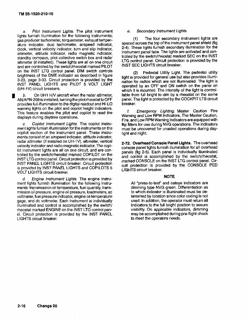
a. Pilot Instrument Lights. The pilot instrument e. Secondary Instrument Lights. lights furnish illumination fo; the following instruments; gas producer tachometer, torquemeter, exhaust temper- ature indicator, dual tachometer, airspeed indicator, clock, vertical velocity indicator, turn and slip indicator, altimeter, attitude indicator, radio magnetic indicator, standby compass, pilot collective switch box and radar altimeter (if installed). These lights are all on one circuit and are controlled by the switchlrheostat marked PILOT on the INST LTG control panel. DIM switch controls brightness of the DME indicator as described in figure 3-23, page 3-33. Circuit protection is provided by the INST PANEL LIGHTS and PILOT 5 VOLT LIGHT (UH-1 V) circuit breakers.
b. On UH1 H/V aircraft when the radar altimeter, ANIAPN-209 is installed, turning the pilot rheostat to OFF provides full illumination to the digital readout and HI-LO warning lights on the pilot and copilot height indicators. This feature enables the pilot and copilot to read the displays during daytime operations.
c. Copilot lnstrument Lights. The copilot instru- ment lights furnish illumination for the instruments on the copilot section of the instrument panel. These instru- ments consist of an airspeed indicator, attitude indicator, radar altimeter (if installed on UH-1V), altimeter, vertical velocity indicator and radio magnetic indicator. The copi- lot instrument lights are all on one circuit, and are con- trolled by the switchlrheostat marked COPILOT on the INST LTG control panel. Circuit protection is provided by INST PANEL LIGHTS circuit breaker. Circuit protection is provided by INST PANEL LIGHTS and COPILOTS 5 VOLT LIGHTS circuit breaker.
d. Engine lnstrument Lights. The engine instru- ment lights furnish illumination for the following instru- ments: transmission oil temperature, fuel quantity, trans- mission oil pressure, engine oil pressure, loadmeters, ac voltmeter, fuel pressure indicator, engine oil temperature gage, and dc voltmeter. Each instrument is individually illuminated and control is accomplished by the switch1 rheostat marked ENGINE on the INST LTG control pan- el. Circuit protection is provided by the INST PANEL LIGHTS circuit breaker.
(1) The four secondary instrument lights are spaced across the top of the instrument panel shield (fig 2-4). These lights furnish secondary illumination for the instrument panel face. The lights are activated and con- trolled by the switchlrheostat marked SEC on the INST LTG control panel. Circuit protection is provided by the INST SEC LIGHTS circuit breaker.
(2) Pedestal Utility Light. The pedestal utility light is provided for general use but also provides illumi- nation for radios which are not illuminated. The light is operated by an OFF and ON switch on the panel on which it is mounted. The intensity of the light is control- lable from full bright to dim by a rheostat on the some panel. The light is protected by the COCKPIT LTS circuit breaker.
f. Emergency Lighting. Master Caution Fire Warning and Low RPM Indicators. The Master Caution, Fire, and Low RPM Warning Indicators are equipped with flip filters for use during NVG operations. The indicators must be uncovered for unaided operations during day- light and night.
2-72. Overhead Console Panel Lights. The overhead console panel lights furnish illumination for all overhead panels (fig 2-5). Each panel is individually illuminated and control is accomplished by the switch/rheostat, marked CONSOLE on the INST LTG control panel. Cir- cuit protection is provided by the CONSOLE PED LIGHTS circuit breaker.
NOTE
All "press-to-test" and cateye indicators are dimming type NVG green. Differentiation as to which indicator is illuminated must be de- termined by location since color coding is not used. In addition, the operator must return all indicators to the full bright position to assure visibility. On applicable indicators, dimming may be accomplished during pre-flight check to meet the operators needs.
2-1 6 Change 20

c. Rotor Tachometer Generator and Power Tur- bine Tachometer Generator. The rotor tachometer gen- erator and power turbine tachometer generator both send signals to the high-low rprn warning light and audio warning circuits. When the warning light only is ener- gized determine the cause of indication by checking the torquemeter and cross referencing other engine instru- ments. A normal indication signifies that the engine is functioning properly and that there is a tachometer gen- erator failure or an open circuit to the warning system rather than an actual engine failure. Electrical power for system operation is supplied by the 28 Vdc essential bus.
d. Light - High Low Limit RPM Warning. The high low warning light (fig 2-4) is located on the instrument panel. This light illuminates to provide a visual warning of low rotor rprn low engine rprn or high rotor rpm.
e. Switch - LOW RPM AUDIO/OFF: The LOW RPM AUDIOIOFF switch is on the engine control panel (fig 2-6). When in OFF position the switch prevents the audio warning signal from functioning during engine starting. Current production helicopters use a spring- loaded switch. When the switch has been manually turned off for engine starting it will automatically return to the AUDIO position when normal operating range is reached.
2-85.1 Oil Debris Detection System (ODDS). ODDS improves oil filtration and reduces nuisance chip indica- tions caused by normal wear particles on detector gaps.
When a chip gap is bridged by conductive particles, a power module provides an electrical pulse which burns away normal wear particles.
f. Powerplant ODDS Components.
(1) Oil separator (Lubriclone) located in en- gine service compartment.
(2) Oil Filter, equipped with 3-micron filter ele- ment, located in engine service compartment.
(3) Chip detector located at bottom of oil sepa- rator. Detector is wired to Engine Chip Detector Caution Capsule.
g. Drive System ODDS Components.
(1) Full-Flow Debris Monitor in transmission sump replaces wafer disc filter.
(2) External Filter with 3-micron element lo- cated in Cargo Sling Compartment (hell hole). Filter re- places existing 25 micron external filter.
(3) Three chip detectors, one in debris moni- tor, and one each in 42 and 90 degree gearboxes. Detec- tors are wired to the Chip Detector Caution Capsule.
h. Electrical System Component. Power module located in overhead in cabin provides electrical power to pulse (burn) away ferrous (iron, steel) debris less than 0.005 inch in cross section. Larger debris will not pulse away, but bridges chip gap and closes the circuit to cau- tion capsule.
SECTION XIV. SERVICING PARKING AND MOORING
2-86. Servicing. c. The helicopter is serviced as follows:
a. Servicing Diagram. Refer to figure 2-1 0. (1) Refer to figure 2-10 for fuel filler location. b. Approved Military Fuels, Oils and Fluids. Refer (2) Assure that fire guard is in position with fire
to table 2-1. extinguisher.
c. Fuel Sample. Settling time for AVGAS is 15 minutes per foot of tank depth and one hour per foot (3) Ground servicing unit to ground stake.
depth for. Jet (JP) fuels. ~ l l o w the fuel to settle for the (4) Ground servicing unit to helicopter. prescribed period before any fuel samples are taken. Tank depth is about 29 inches. (5) Ground fuel nozzle to ground receptacle
located adjacent to fuel receptacle on helicopter. 2-87. Fuel System Servicing.
Servicing personnel shall comply with all safety precautions and procedures specified in FM 10-68 Aircraft Refueling Field Manual.
a. Refer to table 2-1 for fuel tank capacities.
Ensure that servicing unit pressure is not above 125 psi while refueling.
(6) Closed circuit.
(a) Remove fuel filler cap and assure that refuelina module is in locked ~osition. Refer to fiaure - .,
b. Refer to table 2-1 for approved fuel. 2-1 0.
Change 17 2-19

(b) Remove nozzle cap and insert nozzle into fuel receptacle and lock into position.
(c) Activate flow control handle to ON or FLOW position. Fuel flow will automatically shut off when fuel cell is full. Just prior to normal shut off fuel flow may cycle several times as maximum fuel level is reached.
(d) Assure that flow control handle is in OFF or NO FLOW position and remove nozzle.
(7) Gravity or open port: (a) Remove fuel filler cap.
(b) Using latch tool attached to filler cap cable open refueling module.
(c) Remove nozzle cap and insert nozzle into fuel receptacle.
(d) Fill to specified level. (e) Remove nozzle. (f) Close refueling module by pulling
cable until latch is in locked position. Refer to figure 2-1 0. (8) Replace fuel nozzle cap. (9) Replace fuel filler cap. (10) Disconnect fuel nozzle ground.
(1 1) Disconnect ground from helicopter to ser- vicing unit.
(1 2) Disconnect servicing unit ground from ground stake.
(1 3) Return fire extinguisher to designated loca- tion.
d. Rapid (Hot) Refueling. (1) Before rapid refueling.
(a) Throttle - idle.
(b) FORCE TRIM - ON or controls fric- tioned.
(c) Refuel as described in paragraph c. above.
(2) During rapid refueling. A crewmember should observe the refueling operation (performed by authorized refueling personnel) and stand fire guard as required. One crewmember shall remain in the helicopter to monitor controls. Only emergency radio transmission should be made during RAPID refueling.
(3) After rapid refueling, the pilot shall be ad- vised by the refueling crew that fuel cap is secure and grounding cables have been removed.
2-88. Approved Commercial Fuel, Oils, and Fluids.
a. Fuels. Refer to table 2-1
b. Oils. Refer to table 2-1.
c. Fluids. Refer to table 2-1.
2-89. Use of Fuels.
a. There are no special limitations on the use of Army standard or alternate fuels but certain limitations
are imposed when emergency fuels used. A fuel mixture which contains over 10 percent leaded gasoline shall be recorded as all leaded gasoline. The use of emergency fuels shall be recorded in the FAULTIREMARKS column of DA Form 2408-13, Aircraft Maintenance and Inspec- tion Record noting the type of fuel, additives, and dura- tion of operation.
b. When mixing of fuel in helicopter tanks or changing from one type of authorized fuel to another, for example, JP-4 to JP-5, it is not necessary to drain the helicopter fuel system before adding the new fuel.
Table 2-1. Servicing Table of Approved Fuels, Oils, and Fluids.
System Specification
. . . . . . . . . . . . . . . . . . . . . . . . . . . . . . . . . . Fuel MIL-T-5624 (JP-4)l I
Crashworthy System- Total: 208.5 U.S. Gallons (789.2 liters) Usable: 206.5 U.S. gallons (781.6 liters)
Internal Auxiliary Tanks-- Usable: 300 U.S. gallons (11 35.5 liters)
Oil: . . . . . . . . . . . . . . . . . . . . . . . . . . . Engine
. . . . . . . . . . . . . . . . . . . . . . Transmission
42' Gearbox . . . . . . . . . . . . . . . . . . . . . .
. . . . . . . . . . . . . . . . . . 90" Gearbox
Hydraulic System . . . . . . . . . . . . . . . . . .
. . . . . . . . . . . . . . . . . . . Main Rotor Grip
Pillow Block Oil . . . . . . . . . . . . . . . . . . . .
FOOTNOTES Army Standard fuel is MIL-T-5624 (JP-4) NATO code is F-40 Alternate fuels are MI L-T-5624 (JP-5) (NATO F-44) and MIL-T-83133 (JP-8) (NATO F-34). Emergency fuel is MIL-G-5572 (any AV gas) (NATO F-12, F-18, F-22). Refer to TM 55-91 50-200-24.
The helicopter shall not be flown when emergency fuel has been used for a total cumulative time of 50 hours. The engine manual also limits operation to 25 hours when TCP is in the fuel. I
2-20 Change 20

CAUTlClN * Lubrication oil made to MIL-L-7808 by Shell Oil Company under their part number 307, qualification number 7D-1 shall not be used in the engine or air- craft systems. It contains additives which are harmful to seals in the sys- tem.
I *
MIL-L-7808 NATO code is 0-148. For use in ambient temperatures below minus 32"C/25"F. May be used when MIL-L-23699 or DOD-L-85734 oil is not available. Not for use in main rotor hub PIN 204-012-101-31.
CAUTION Under no circumstances shall MIL-L-23699 or DOD-L-85734 oil be used in ambient temperatures below minus 32'C/2SoF.
MIL-L-23699 NATO code is 0-156 for use in ambient temperatures above minus 32"C/25"F. Not for use in main rotor hub PIN 204-01 2- 101 -31.
DO not mix MIL-L-2104, MIL-L-46152, MIL-L-46167, MIL-L-23699, DOD-L-85734, and or MIL-L-7808 oils, except during an emergency. If the oils are mixed the system shall be flushed within six hours and filled with the proper oil. An entry on DA Form 2408-13-1 is required when the oils are mixed.
MIL-H-5606 NATO code is H-515. For use in ambient temperatures below minus 35" C/3O0 F. (Refer to TB 55-1 500-344-25).
For use in ambient temperatures above minus 35"C/3O0F.
WARNING
Prolonged contact with hydraulic fluid or its mist can irritate eyes and skin. After any prolonged contact with skin, immediately wash contacted area with soap and water. If liquid contacts eyes, flush immediately with clear water. If liquid is swallowed, do not induce vom- iting; get immediate medical attention. When fluid is decomposed by heating, toxic gases are released.
I It is not advisable to mix MIL-H-5606
and MIL-H-83282 fluids, except during an emergen- cy. An entry on DA Form 2408-13-1 is required when the fluids are mixed. When changing from MIL-H-5606 to MIL-H-83282, not more than two per- cent of MIL-H-5606 may be present in the system.
MIL-L-2104, MIL-L-46152, MIL-L-46167, must be used in hub PIN 204-01 2-1 01 -31 as follows:
"" 1 - -
Average Temp Range Specifications
+S0Candabove . . . . . . MIL-L-2104, Grade 40, NATO Code 0-230
-18°C to + 5°C . . . . . . . . MIL-L-2104, Grade 30, NATO Code 0-230 or MIL-L-46152, Grade 30
-29"Ct0-18"C . . . . . . . . MIL-L-2104, Gradelo,
NATO Code 0-230 or MIL-L-46152, Grade 1 OW30
-54°C to -20°C . . . . . . . . MIL-L-46167, DEXRON I1 Automatic transmission fluid.
Approved domestic commercial fuels (spec. ASK 0-1 655-70: Manufacturers designation-
Jet B-JP4 Type Jet A-JP5 Type Jet A-I -JP8 Type
American JP-4 AeroJet B
B.P.A.T.G. Caltex Jet B
Conoco JP-4 Gulf Jet B Jet A-I WXON Turbo Fuel
B
Mobil Jet B Philjet JP-4 Aeroshell JP-4
Chevron B Texaco Avjet 6
American Type A AeroJet A AeroJet A-I
Richfield A I
B.P.A.T.K. Caltex Jet A-1
ClTGO A I
Conoco JetBO Conoco Jet-60
Gulf Jet A Gulf
EXXON A EXXON A-1 I
Mobil Jet A Mobil Jet A-1 Philjet A-50 Aeroshell640 Aeroshell650 SuperJet A Superjet A-1 Jet A Kerosine Jet A-1 Kerosine I Chevron A-50 Chevron A-1 Avjet A Avjet A-1
Union JP-4 76 Turbine Fuel I
Refer to stencil on grip assembly to de- termine proper lubrication requirements.
Change 20 2-2 1

Approved foreign commerical fuels:
Country F-40 F-44
Belgium BA-PF-26
Canada 3GP-22F 3-6P-24e
Denmark JP-4 MI L-T-5624
France Air 3407A s
Germany (West) VTL-9130-006 UTL9130-0071 UTL 9130-010
Greece JP-4 MIL-T-5624
Italy AA-M-C-1421 AMC-143
Netherlands JP-4 D. Eng Rd MIL-T-5624 2493
Norway JP-4 MIL-T.5624
Portugal JP-4 MIL-T-5624
Turkey
United Kingdom D. Eng Rd 2454 E. Eng Rd 1 (Britain) 2498
NOTE
Anti-icing and Biocidal Additive for Commercial Tur- bine Engine Fuel -The fuel system icing inhibitor shall conform to MIL-1-27686. The additive provides anti- icing protection and also fk~r~ctions as a biocidt? to kill microbial growths in helicopter fuel systems. Icing inhibitor conforrr~ing to MIL-1-27686 shall be added to commercial fuel, not containing an icing inhibitor, dur- ing refueling operations regardless of ambient tem- peratures. Refueling operations shall be accom- plished in accordance with accepted commercial pro- cedures. Commercial product "PRIST conforms to MIL-1-27686. Approved domestic commercial oils for MIL-L-7808: Manufacturers designation-PQ Turbine Oil 8365 ESSOIENCO Turbo Oil 2389 FM-184AlRM-201A151
CAXI-O_N
Do not use Shell Oil Co., part No. 307, qualification No. 7D-1 oil (MIL-L-7808). It can be harmful to seals made of silicone.
Approved domestic commerc~al oils for MIL-L-23699: Manufacturers designaton- PQ Turbine Lubricant 5247/6423167001773 11887819595
Brayco 8991899-Gl899-S Castrol 205 Jet Engine Oil 5 STO-21919/STO-21919A/STD-6530 HATCOL 321 1 1361 1 Turbo Oil 2380 (WS-6000)/2395 (WS-6459)/2392/2393 Mobil Jet II RM-139NMobil Jet II RM-147NAvrex S Turbo 2601Avrex S
I Turbo 265 Royco 899 (C-915)/899SC/Stauffer Jet II Aeroshell Turbine Oil 500 Aeroshell Turbine Oil 550 Chevron Jet Engine Oil 5 Stauffer 6924lJet II SAT0 737717730,TL-8090
Approved domestic commercial fluids for MIL-H-5606
I Manufacturers designation- "PO" 4226 Brayco 7578 Brayco 756C Brayco 7561 D Hyspin A Univis J41 Aero HFB Petrofluid 56068 Petrofluid 4607 Royco 782 Royco 756ClD XSL 7828 PED 3565 PED 3337 TL-5874 Aero Hydroil 500 YT-283 FP-221
Approved domestic commercial fluids for MIL-H-83282: Brayco Micronic 882 Hanover R-2 HF 832 ROYCO 782 XRM 230A XRM 231A
2-22 Change 20

J 1 J ,J
CAUTION PANEL Y-
* May not be installed on all configurations.
Figure 2-9. Caution Panel - Typical
CAUTION PANEL WORDING
ENGINE OIL PRESS
SPARE
SPARE
ENGINE CHIP DET
LEFT FUEL BOOST
RIGHT FUEL BOOST
ENG FUEL PUMP
20 MINUTE FUEL
FUEL FILTER
*GOV EMER
AUX FUEL LOW
XMSN OIL PRESS
XMSN OIL HOT
HYDPRESSURE
"ENGINE INLET AIR
INST INVERTER
DC GENERATOR
EXTERNAL POWER
CHIP DETECTOR
* IFF
Change 20 2-35
FAULT CONDITION
Engine oil pressure below 25 psi
Not connected
Not connected
Metal particle in engine oil
Left fuel boost pump inoperative
Right fuel boost pump inoperative
Engine fuel pump inoperative
Fuel quantity about 185 Ibs
Fuel filter Impending bypass
Governor switch in emergency position
Auxiliary fuel tank empty
Transmission oil pressure below 30 psi
Transmission oil temperature above 11 0" C
Hydraulic pressure Low
Engine air filter clogged
Failure of inverter
DC Generator failure
External power access door open
Metal particles present in 42" or 90" gearbox or main transmission
IFF System inoperative

Figure 2-10. Servicing Diagram-Typical (Sheet 1 of 2)

1. Frequency indicator 2. Communicstion test switch 3. Volume control 4. Kilohertz selector S . O f T / p o w e r ~ 6. Megahertz selector
Figure 3-8. VHF Control Panel C-7197lARC-134
CONTROUINDICATOR
OFF-PWR switch
VOL control
COMM-TEST switch
Megahertz control
Kilohertz control
Change 7
FUNCTION
Turns power to the set ON-OFF.
Controls the receiver audio volume.
Turns squelch ON or OFF.
Selects whole number part of operating frequency.
Select the decimal number part of the operating frequency.
(4) SQ and VOL controls - Adjust.
(5) Transmit interphone selector switch -No. 3 position.
d. Emergency Operation. Select guard frequency 121.500 MHz.
3-12. FM Radio Set - ANIARC-114 and -114A.
a. Description. The FM Radio Set provides two way frequency modulated (FM) narrow band voice com- munications and homing capability within the frequency range of 30.00 to 75.95 MHz on 920 channels for a dis- tance range limited to line of sight. A guard receiver is incorporated in the set and is fixed tuned to 40.50 MHz. It has the additional capability for retransmission of voice, or X-mode communications in conjunction with radio set ANIARC-131. The radio set is marked VHF FM COMM and is mounted on the center console, on helicopter seri- al Nos. 71 -20000 and subsequent.
b. Controls and Functions. Refer to figure 3-10.
c. Operation.
(1) Two Way Voice Communication.
(a) Function selector - As desired.
(b) Frequency - Select.
(c) RCVR TEST - Press to test.
(d) AUDIO - Adjust.
(e) Transmit interphone selector - No. 5 position.
(2) Retransmission.
NOTE
For transmission both FM circuit breakers must be in.
(a) Frequencies - Select (both FM sets).
(b) Communications - Establish with each facility by selecting number 1 position and then number 5 position on the transmit-interphone selector.
(c) Function selectors - RETRAN (both FM sets).
(d) Receivers switches - Number 1 and number 5 positions as desired for monitoring.
d. Emergency Operation. Select guard frequency 40.50 MHz.
3-1 3. FM Radio Set - ANIARC-131.
a. Description. The FM Radio Set consists of a receiver-transmitter, remote control panel unit; commu- nication antenna and a homing antenna. The radio set provides 920 channels spaced 50 kHz apart within the frequency range of 30.00 to 75.95 MHz. Circuits are in- cluded to provide transmission sidetone monitoring. The control panel is located on the pedestal. Homing data is displayed by the course indicator (fig 3-20) on the instru- ment panel. A channel changing tone should be heard in the headset while radio set is tuning. When the tone stops, the radio set is tuned. Operation in DIS position is possible; however flags on course deviation indicator will be inoperative. When the first FM radio set is in the hom- ing mode, the homing indicator may deflect left or right of on course indication while the second FM radio set is keyed.
b. Controls and Functions. Refer to figure 3-1 1.
c. Operation. Depending on the settings of the control panel controls, the radio set can be used for the following types of operation: Two way voice communica- tion and homing (fig 3-1 2).
(1) Two Way Voice Communication.
(a) Mode control switch - T/R (allow two minute warm up).
(b) Frequency - Select.
(c) RECEIVERS No. 1 switch - ON.
(d) VOL control - Adjust.
(e) SQUELCH control - Set for desired squelch mode.
(9 TRANS selector switch - No. 1.
(2) Homing Operation.
(a) Mode control switch - HOME.
(b) Frequency - Adjust to frequency of selected homing station.
(c) SQUELCH control may be set to CARR or TONE, however, the carrier squelch is automat- ically selected by an internal contact arrangement on HOME position.
(d) Fly helicopter toward the homing sta- tion by heading in direction that causes homing course deviation indicator right-left vertical pointer to position itself in the center of indicator scale. To ensure that heli- copter is not heading away from the homing station, change the heading slightly and note that the course deviation indicator vertical pointer deflects in direction opposite that of the turn.
3-12 Change 20

(3) Retransmit Operation. Start the equipment and proceed as follows for retransmit operation:
(a) Mode controls (both control units) - RETRAN.
(b) SQUELCH controls (both control units) - Set as required. Do not attempt retransmit operation with SQUELCH controls set to DIS. Both controls must be set to CARR or TONE. To operate satisfactorily the two radio sets must be tuned to frequencies at least 3 MHz apart.
(c) Frequency adjust (both control units) for the desired operation.
(4) Stopping Procedure. Mode control switch - OFF.
3-14. FM Radio Set ANIARC-54.
a. Description. The FM Radio Set provides two- way communications within the frequency range of 30.00 to 69.95 MHz. Voice communication permits selective calling (TONE) and when used with the homing antenna and course indicator the pilot is provided with a homing facility. A channel changing tone should be heard in the headset while radio set is tuning. When the tone stops the radio set is tuned. Voice reception is possible in HOME position. With two or more FM radio sets installed and the first FM radio set is in the homing mode, the homing indicator may deflect left or right of on-course indication while the second FM radio set is keyed.
6. Controls and Functions. Refer to figure 3-1 2.
c. Operation.
(a) FM mode selector switch - PTT (allow three minute warmup).
(b) Frequency - Select.
(c) FM VOL control - Adjust.
(d) FM SQUELCH control - CARR (or as desired).
(e) RECEIVERS switch No. 1 - ON.
(9 TRANS selector switch - No. 1.
(g) Microphone switch - Press.
(2) Homing Operation. FM mode selector switch - HOME.
(3) Retransmit Operation. Start the equipment and perform the following for retransmit operation.
(a) Mode controls (both control units) RE- TRAN.
(b) SQUELCH controls (both control units) Set as desired.
NOTE Do not attempt retransmit operation with the SQUELCH controls set to DIS. Both controls must be set to CARR or TONE.
(c) Adjust frequency (both control units) desired operation. To operate satisfactorily the two radio sets must be tuned to frequencies at least 5 MHz apart.
(4) Stopping Procedure. FM mode selector switch - OFF.
3-1 5. FM Radio Set ANIARC-44
a. Description. The FM Radio Set provides two way communications within the frequency range of 24.0 to 51.9 MHz on 280 preset channels. Signal distribution panel SB-329 and control panel assembly 204-075-219 (FM switch assembly), to provide squelch control and power to the antenna group are used in conjunction with the FM Liaison Radio Set (fig 3-2 and fig 3-14). The set provides a homing facility on signals between 24.0 and 49.0 MHz. Cycling may take place in the receiver-trans- mitter. This will be indicated by a 400-cycle-per-second signal heard in the headset.
b. Controls end Functions. Refer to figure 3-13.
c. Operation.
(1) Preliminary Setup.
(a) FM power switch - ON.
(b) FM home switch - Down
(c) TRANS selector switch -- No. 1 posi- tion.
(d) REM-LOCAL switch -- LOCAL.
(e) Frequency - Select.
(2) Standing Procedures.
(a) BAT switch - - ON (OFF for APU).
(b) INT and FM circuit breakers - In.
Change 17 3-12.1

(c) ICS switch - Up (allow three minute warm up).
(3) lnterphone Operation.
(a) Microphone switch - Press.
(b) Speak into the microphone - Adjust interphone volume.
(4) FM Receive-Transmit Operation.
(a) ICS switch - Up.
(b) FM ON-OFF power switch - ON.
(c) FM VOL control - As desired.
(d) TRANS selector switch - No. 1 posi- tion.
(e) Microphone switch - Press to trans- mit.
(5) FM Home Operation. FM HOME switch - UP.
(6) Stopping Procedures.
(a) FM HOME switch - Down.
(b) FM POWER switch - OFF.
(c) ICS Switch - Down.
3-16. Voice Security Equipment - TSECIKY-28.
a. Description. The Voice Security Equipment is used with the FM Command Radio to provide secure two way communication (figs 3-1 1 through 3-1 4). The equip- ment is controlled by the control-indicator mounted in the pilot right console. The POWER switch must be in the ON position regardless of the mode of operation whenever the equipment is installed.
b. Control and Functions. Refer to figure 3-14.
c. Operation. Normal operation will exist without its encoderldecoder and control indication being installed in the helicopter. However two operation modes are available when they are installed. PLAIN mode for unciphered radio transmission or reception and CIPHER mode for ciphered radio transmission or reception. Both modes may be operated with or without retransmission units.
(1) Preliminary
(a) Set the control indicator POWER switch to ON.
(b) Apply power to FM radio set.
(c) When power is initially applied an auto- matic alarm procedure is initiated.
1. A constant tone is heard in the headset and after -
approximately two seconds the constant tone will change to an interrupted tone.
2. To clear the interrupted tone press and release - the press to talk switch the interrupted tone will no longer be heard and the circuit will be in a standby condition ready for either transmission or recep- tion. No traffic will be passed if the interrupted tone is still heard after pressing and releasing the press to talk switch.
(d) Set control unit function switch for de- sired type of operation (2 and 3 below).
(2) Plain Mode.
(a) Set the control indicator POWER switch to ON.
(b) Set the PLAIN-CIPHER switch to PLAIN (indicated by red light).
(c) Set the RE-X-REG switch to REG; ex- cept when operating with retransmission units, at which time switch will be placed in the RE-X position.
(d) Press the press to talk switch and speak into the microphone to transmit. Release the press to talk switch for reception.
(3) Cipher Mode.
(a) Set the PLAIN-CIPHER switch to CI- PHER (indicated by a green light).
(b) Place the RE-X-REG switch to REG except when operating with retransmission units at which time the switch will be placed in RE-X position.
(c) To transmit press the press to talk switch. DO NOTTALK; in approximately one-half second a beep will be heard. This indicates the receiving station I is now capable of receiving your message. Transmission can now commence. Only one voice security system can transmit on a given frequency. Always listen before at- tempting to transmit to assure that no one else is trans- mitting.
3-12.2 Change 20

Receiver is installed, data is presented by the horizontal pointer and GS warning flag.
b. Controls and Functions. Refer to figure 3-20.
c. Operation. Refer to the applicable VHF Naviga- tion Receiver and/or FM Radio set operating procedures.
3-23. Gyromagnetic Compass Set.
a. Description.
(1) The Gyromagnetic Compass Set is a direc- tion sensing system which provides a visual indication of the magnetic heading (MAG) of the helicopter. The infor- mation which the system supplies may be used for navi- gation and to control flight path of the helicopter.
(2) A radio magnetic indicator is installed in the pilot instrument panel. A second radio magnetic indicator (not shown) is installed in the copilots instrument panel. The copilot indicator is a repeater type instrument similar to the pilot indicator except that it has no control knobs. The moving compass card on both indicators displays the gyromagnetic compass heading. The number 1 pointer on the indicators indicate the bearing to the NDB or course to the VOR station. The number 2 pointer indi- cates the VOR course to station.
(3) The system does not have a "fast-slew- ing" feature. If the compass is 180" off the correct heli- copter heading when the system is energized it will take approximately 1 hour and 30 minutes (2" per minute) for the compass to slave to the correct headings.
b. Controls and Functions. Refer to figure 3-21.
c. Operation.
(1) INV switch - MAIN or STBY.
(2) Radio magnetic indicator (pilot only)- Check power failure indicator is not in view.
(a) Slaved gyro mode.
I 1, COMPASS switch - MAG or IN.
2. Synchronizing knob - Center (Null) annunciator. -
3. Magnetic heading - Check. -
(b) Free gyro mode.
1. COMPASS switch - DG or OUT. -
2. Synchronizing knob - Set heading. -
3. Annunciator - Center position and then does not change (annunciator is de-energized in the free gyro (DG) mode).
(c) lnflight operation
1. Set the COMPASS switch to DG, OUT, MAG or - IN as desired for magnetically slaved or free gyro mode of operation. Free gyro (DG or OUT) mode is recommended when flying in latitudes higher than 70 degrees.
2. When operated in the slaved (MAG or IN) mode, I - the system will remain synchronized during nor- mal flight maneuvers. During violent maneuvers the system may become unsynchronized, as indi- cated by the annunciator moving off center. The system will slowly remove all errors in synchro- nization however, if fast synchronization is de- sired turn the synchronizing knob in the direction indicated by the annunciator until the annunciator is centered again.
31 When operating in the free gyro (DG or OUT) mode, periodically update the heading to a known reference by rotating the synchronizing knob.
3-24. Marker Beacon Receiver.
a. Description. The Marker Beacon Receiver set is a radio aid to navigation. It receives 75 MHz marker beacon signals from a ground transmitter to provide the pilot with aural and visual information. The marker bea- con controls and indicator are located on the instrument panel to aid in determining helicopter position for naviga- tion or instrument approach.
b. Controls and Functions. Refer to figure 3-22.
c. Operation.
(1) VOLUME OFFIINCR control-ON.
(2) Receiver NAV switch (MB switch if SB-329/AR panel is used) - On.
(3) Volume - Adjust.
(4) SENSING HIGHILOW switch-As de- sired.
d. Stopping Procedures. VOLUME OFFIINCR control - OFF.
Change 20 3-29

RADIO POINTER NO. 2
CONTROUINDICATOR
Pointer No. 1
Pointer No. 2
Synchronizing control
SET HDG control
Heading select cursor
ADFNOR control
Fixed index
Rotating compass card
Annunciator
Power failure indicator (OFF) (flag) Compass switch (located on pilots instrument panel)
FUNCTION
lndicates course to ADF or VOR radio station.
lndicates course to VOR station.
Is manually rotated to null annunciator and synchronize compass system.
Moves the heading select cursor to desired heading.
lndicates desired heading.
Selects ADF or VOR for pointer No. 1
Provides reference mark for rotating compass card.
Rotates under fixed index to indicate helicopter magnetic heading.
Show dot (0) or cross (+) to indicate misalignment (non- synchronization) of compass system.
Shows to indications loss of power to compass system.
MAG or IN position slaved gyro mode DG or OUT position free gyro mode.
Figure 3-21. Gyromagnetic Compass Indicator (RMI)
3-30 Change 17

1 c. Operation.
1 (1) Normal ADF Operation.
I a. ICS NAV receiver selector - ON. ~ b. Mode selector switch - ADF.
c. Frequency - Select.
d. MAN121 821500 switch - MAN.
e. HSI/VSI MODE SEL BRG 2 switch - ADF.
f. VOL control - as desired.
9. TESTrrONE control - TEST. Verify the RMI pointer No. 2 rotates 90 degrees from present bear- ing. Release test switch.
(2) ANT Mode Operation (Optional).
a. Mode selector switch - ANT,Monitor re- ceiver by listening.
b. ICS NAV switch - ON.
d. Stopping Procedures. Mode selector switch - OFF.
I 3-46. RADIO RECEIVING SET ANIARN-123(V) (VORI ILSIMB).
a. Description. Radio set ANIARN-123 (V) (Fig- ure 3-29.5) is a very high frequency receiver that oper- ates from 108.00 to 117.95 MHz. Course information is presented by the HSI course deviation pointer and the selectable No. 2 bearing pointer on the horizontal situa- tion indicator. The combination of the glide slope capabil- ity and the locaiizer capability makes up the instrument landing system (ILS).
(1) The marker beacon portion of the receiv- er visually indicates to the right of either the ID-2103 or ID-988 a MB advisory light. A Tone can be heard in the headphones of passage of the helicopter over a marker beacon transmitter.
Change 20 3-68.3/(3-68.4 blank)


(2) The receiving set may be used as a VOR I receiver, or ILS receiver. The desired type of operation is selected by tuning the receiving set to the frequency corresponding to that operation. ILS operation is se- lected by tuning to the odd tenth MHz frequencies be- tween 108.0 and 11 2.0 MHz. VOR operation is selected by tuning in .050 MHz units to the frequencies between 108.0 and 11 7.95 MHz. However, the odd tenth MHz between 108.0 and 11 2.0 MHz are reserved for ILS op- eration.
(3) The three receiver sections do the in- tended functions independent of each other.
Performance degradation within any one of the major sections will not affect the performance of the others. Power for the ANIARN-123 is provided from the dc es- sential bus through a circuit breaker, marked VOR/ILS.
NOTE
Tuning to a localizer frequency will automati- cally tune to a glide slope frequency, when available.
b. Controls and Functions. Refer to Figure 3-29.25.
1 HUNDREDTHS MEGAHERTZ FREQUENCY MEGAHERTZ TUNE 'ONTRoL INDICATOR TUNE CONTROL
Figure 3-29.25. Radio Receiving Set ANIARN-123 (V).
Change 20 3-69

Controls and Functions for VOR/ILS/MB Receivers
c. Operation. (2) VORIMarker Beacon Test.
CONTROL
NAV VOL-OFF control
MB VOL-OFF control
Megahertz tune control
Hundredths megahertz tune con- trol
VORIMB TEST control
MB SENS HI-LO control
LO
HI
(1) Starting Procedure.
FUNCTION
Turns VOR/ILS receiver on and off, adjusts volume.
Turns marker beacon receiver on and off; adjusts volume.
Tunes VORIILS receiver in MHz as indicated on frequency indicator.
Tunes VORIILS receiver in hundredths MHz as indicated on frequency indicator.
Activates VOR test circuit and MB receiver lamp self-test circuits.
For controlling ME3 sensitivity.
Decreases receiver sensitivity: Results in shortening time transmitted signal will be received.
Increases receiver sensitivity: Results in lengthening time transmitted signal will be received.
(a) HSI CRS set - 315 on COURSE set display.
(a) ICS AUX selector - ON. (b) VORIMB TEST switch - down and
(b) NAV VOL OFF control - ON. hold. The MB light on the VSI should go on.
(c) HSI VORILOC course bar - centered . . (c) Frequency - Select. +- 1 dot.
(d) MODE SEL BRG 2 switch - VOR. (d) No. 2 bearing pointer - Should indicate between 310" to 320" position. I
(e) MODE SEL VORIILS switch - ON. (e) VOR/MB TEST switch - Release.
3-70 Change 19

(3) Communications Test. (b) MB SENS switch - as desired.
(a) ICS AUX receiver selector - ON.
(b) NAV VOL control -Adjust to midrange.
(c) VOR/MB TEST switch - Down and hold. Noise should be heard in headphones.
(d) VORIMB TEST switch - Release. Noise should not be heard in headphones, indicating that squelch is operation properly.
(e) VORIMB TEST (ID-45311 347 EQUIPPED AIRCRAFT)
1. COURSE SELECTOR Knob - Rotate to 315" un- - der course pointer or reciprocal pointer.
2. VORIMB TEST Switch - Down and hold. The MB - light on the instrument panel should go on.
3. The OBS VERTICAL Pointer - Centered 54"
4. NO. 2 BEARING Pointer - Between 311319" - position.
5. COURSE SELECTOR Knob - Rotate each side of - centered indication by 10". Vertical pointer should indicate between 8-1 0" from centered indication.
6. COURSE SELECTOR Knob - Rotate 90" from - centered indication. To-from flag should change.
7. VORIMB TEST Switch - Release. - (4) VOR Operation. Course - Set.
(5) ILS (LOCIGS) operation. ILS operation fre- quency - Set.
(6) Marker Beacon (MB) Operation.
(a) MB VOL OFF switch - ON.
(7) VOR communications. Receiving Opera- tion. Frequency - Set.
(8) Stopping Procedure. NAV VOL OFF switch - OFF.
3-47. DOPPLER NAVIGATION SET ANIASN-128.
a. Descri~tion. The doppler navigation set, AN1 ASN-128, in conjunction with the helicopter's heading and vertical reference systems, provides helicopter ve- locity position. It also provides steering information from ground level to 10,000 feet. The doppler navigation sys- tem is a completely self-contained navigation system and does not require any ground-based aids.
(1) The system provides world-wide naviga- tion, with position readout available in both Universal Transverse Mercator (UTM), and Latitude and Longitude (LATILONG). Navigation and steering is done using LATI LONG coordinates, and a bilateral UTM-LATILONG con- version routine is provided for UTM operation. Up to ten destinations may be entered in either format and not necessarily the same format. Preset position data entry format is also optional and independent of destination format.
(2) The ANIASN-128 operates in conjunction with the Horizontal Situation lndicator (HSI) and a Hori- zontal Situation lndicator Control (HSI Control). A Com- pass Control C-8021lASN-75 is also included to syn- chronize Gyromagnetic Compass Set ANIASN-43 to correct magnetic heading. This is accomplished when in the SLAVED mode of operation.
b. Controls, Displays, and Function. The controls and displaysforthe doppler are on the front panel (Figure 3-29.26).
Change 20 3-71

LEFF CENTER RIGHT TARGET DISPLAY DISPLAY DISPLAY STmAGE LAMPS LAMPS LAMPS I INDICATOR
Figure 3-29.26. Doppler Navigation Set ANIASN-128.
OFF
LAMP TEST
Controls and Functions of Doppler Navigation Set.
Turns navigation set off.
Checks operation of all lamps.
CONTROUINDICATOR
Mode Selector
1 TEST I Initiates built-in-test exercises for navigation set.
FUNCTION
Selects Doppler Navigation of operation.
Selects Universal Transverse Mercator (UTM) navigational mode of operation
I LATILONG I Select latitudellongitude navigational mode of operation.
BACKUP Places navigation set in estimated mode of operation or estimated velocity mode of operation.
I DISPLAY Selector I Selects navigation data for display.
1 WIND SPIDIR I Not applicable.
XTK-TKE (Left Display) (Right Display)
3-72 Change 7
Distance crosstrack (XTK) of initial course to destination in km and tenths of a km. Track angle error (TKE) in degrees displayed as right or left of bearing to destination.
GS-TK (Left Display) Ground speed (GS) in (Left Display) kmlhr.

4-20. Before Leaving Helicopter-M52 Smoke Gener- ator Subsystem.
1. System - check for leaks.
2. Ring - Condition and security.
SECTION II. MISSION AVIONICS
4-20.1 Communications Command Console AN/ (2) The PLRS system provides timely and ac- ASC-15Ao 1, 2, 3, 4 (if installed). curate positioning information in support of tactical com-
e. The communications command console pro- vides tactical commands with air-to-ground command and control communications in a battlefield environment. The console provides ground-air ground automatic se- cure transmission from an airborne platform and a Posi- tion Locating Reporting System (PLRS).
f. Use:
(1) When installed in the UH-1 H helicopter, AN/ I ASC-15A(V)3,4, configured in the command post mode,
can be used as a forward area airborne command and observation post. This mode provides six separate inter- communication stations. Three of the six stations have control of three separate very high frequency, frequency- modulated (VHF-FM) radio communicator links (V3) or two VHF-FM links (V4), and one ultra high frequency, amplitude-modulated (UHF-AM) link.
mander.
(3) The VHF-FM links have voice encryption capabilities if the TSECIKY-28 or TSECIKY-58 security equipment is employed. The UHF-AM link cannot be voice encrypted.
(4) The intercommunication control set pro- vides intercommunication circuit for two-way voice com- munications between the operator; pilot, copilot, com- munications officer or observer.
(5) The regenerative repeater is used with two FM receiver-transmitter units to automatically retransmit plain or secure voice message from two other receiver- transmitter units which are too far apart to communicate with each other using normal communications.
g. ANIASC-15A(V) 1, 2, 3, and 4 equipment con- figuration. Refer to Figure 3-30. I
SECTION Ill. CARGO HANDLING
Paragraphs 4-21. through 4-26. and table 4-1 have 4-23. Deleted been deleted. This includes all data from pages 4-5 through 4-8. 4-24. Deleted
4-21. Deleted 4-25. Deleted
4-22. Deleted 4-26. Deleted
Change 17 4-5/(4-6 blank)


NOTE During hoist operation overtravel of the cable assembly may occur in the extended mode of operation after stopping hoist operation in MID-TRAVEL. Cable over-travel should not exceed 10 feet. If cable overtravel is ob- served, refer hoist to maintenance for repair.
4-27. High Performance Hoist. Provisions have been made for the installation of an internal rescue hoist (Fig- I ure 4-2). The hoist my be installed in any one of four
positions in the helicopter cabin. The hoist installation consists of a vertical column extending from the floor structure to the cabin roof, a boom with an electrically powered traction sheave, and an electrically operated winch. Two electrical control stations for the operation of the rescue hoist are provided, one for the pilot, and one for the hoist operator. A control switch is located on the cyclic control stick and provides up and down operation of the hoist as well as positioning the boom (Figure 2-5). A pendant control is provided for the hoist operator and contains a boom positioning switch and a toggle switch for hoist operation (Figure 4-6). The pilot control willover- ride the hoist operators control. A pressure cartridge cable cutter is provided with two guarded cable cutter switches. The pilot cable cutter switch is mounted on the pedestal and the hoist operators cable cutter switch is mounted on the back of the hoist control box. The high
performance hoist is an electronically speed controlled unit. Speed varies from 125 fpm at 600 pounds to 250 fpm at 300 pounds. The winch has four positive action switches. Number One is an all-stop switch that opens when three wraps of cable remain on drum. Number Two is a deceleration switch that opens when five wraps of cable remain on drum. Number Three switch has two functions, operates caution indicator light on control pen- dant (when caution light is on, a cable deceleration should occur) and limits cable speed when hook is 8 to 10 feet from up-stow position. Number Four switch fur- ther limits cable speed when hook is 12 to 18 inches from the up-stow position. The first and last 20 feet of the cable are painted red. An elapsed time meter and power- on indicator are located on the control panel. A pistol grip control (Figure 4-3) is provided for the hoist operator and contains a boom inlout switch, a variable speed control, cable limit and overtemperature indicator (when hoist operating temperature limit has been exceeded the over temp light will come on). (Secure hoist as soon as opera- tions permit), and an intercommunication switch. The hoist has 250 feet of usable cable. Power is provided by the NONESSENTIAL BUS (controlled by the ESSEN- TIAL BUS). Circuit protection is provided by the RES- CUE HOIST POWER, RESCUE HOIST CONT, and RESCUE HOIST CABLE CUTTER circuit breakers. RESCUE HOIST CABLE CUTTER circuit breaker con- trols only the pilot's cable cutter switch.
(4-7 blank)/4-8 Change 20

4-28. Preflight Procedures. 11. SPEED MODE switch - High.
If hoist is installed check for installation of safety clip.
1. Check that vertical shaft for ceiling attaching point is raised vertically to prevent the ceiling attaching device from disconnecting.
2. Oil level - Check in hoist and boom head.
3. RESCUE HOIST CONT, RESCUE HOlST POWER AND RESCUE HOlST CABLE CUlTER circuit breakers - Check out.
4. CABLE CUT switches (pilot and hoist operator) guard - Down and safetied.
5. Deleted.
6. Boom sheave - Check that no foreign matter is entrapped at sheave.
7. GPU - Connect to helicopter.
8. RESCUE HOlST CONT and RESCUE HOlST POWER circuit breakers - In. Blue POWER ON light and yellow CAUTION light should be on and fan should be operating.
9. BOOM switch (Pendant) - Rotate boom out and in, check hoist switch (pilot) override during opera- tion.
10. HOlST switch (pilot) - Rotate boom out.
12. HOlST switch (pilot) - Down. Reel cable out until caution light is out on pendant (approximately 10 feet).
13. HOlST control switch (pilot) -Reel in cable and I observe that cable speed slows when caution light comes ON (approximately 10 feet).
14. Boom up limit switch actuator arm-Push up on arm during reeling in to check that hoist stops running when up limit switches are actuated. Observe that cable speed slows when hook is 12 to 18 inches from the full up position when cable is reeled in with no load on hook.
15. Repeat steps 12 through 14 using the boom switch (pendant). Check that cable speed can be regu- lated by the control from 0 to 250 feet per minute when I cable is reeled out beyond the 10 feet caution limit. (Cau- tion light is out). Check pilots override during reeling out and in.
16. SPEED MODE switch - LOW SPEED and re- peat steps 12 through 15.
17. Hoist switch (pilots) - Rotate boom in the stowed position.
18. RESCUE HOlST CONT, RESCUE HOlST POWER and RESCUE HOlST CABLE CUTTER circuit breakers - Out upon completion of preflight check.
4-29. Operating Procedures.
1. RESCUE HOlST CONT, RESCUE HOlST POW- ER and CABLE CUTTER breakers - In.
2. Blue POWER ON and yellow CAUTION indicator lights should be on.
The cable should be reeled out and in within 30 degrees of vertical during these checks. Care should be taken to avoid twisting the cable which will cause it to kink. Hands must be kept off hoist boom during
operation to prevent hand entrapment NOTE and iniury.
Observe the condition of the hoisting cable to assure that there are no broken
7 7
3. BOOM switch - Rotate boom out.
wires or kinks. 4. SPEED MODE switch - As required.
Change 20 4-9

5. HOlST switch - DOWN. Adjust cable reel-out speed as required. CAUTION light should be out when 8 to 10 feet of cable is reeled out.
6. HOlST control switch- UP and adjust cable reel- in speed as required. CAUTION light should be ON when rescue hook is 8 to 10 feet from up stow position. Reel cable completely up.
When hoist is installed in positions 1 Or4, the boom head assembly and hook as- sembly could bump the pilot/copilot hel- mets if stowed behind seat back.
NOTE When an internal auxillary fuel tank is installed, it shall be on the opposite side of the helicopter from the hoist. If a pair of auxiliary fuel tanks are installed, the fuel shall be used evenly from both tanks or used first from one tank that is on the same side as the hoist.
7. BOOM OUTIIN switch - Rotate boom in.
8. RESCUE HOlST POWER, RESCUE CONT and CABLE CUTER circuit breakers - Out.
4-30. Before Takeoff. RESCUE HOlST CABLE CUT- TER, RESCUE HOlST CONT and RESCUE HOlST POWER circuit breakers - Out.
4-31. lnflight Procedures.
Operations during gusty or turbulent wind conditions may result in contacting the lateral cyclic control stops. During hoisting operations the helicopter should be positioned to maximize the control margins.
1. Hover over pick-up location.
2. Use operating procedudres as required.
3. Pilot should lift load off ground by increasing col- lective to ensure helicopter control with the load. 1
When a load is attached on the hoist hook (and if conditions permit), it is advisable not to make abrupt changes in helicopter attitude until load is aboard or raised as close as possible. G-forces on hoist could become excessive if hoist load is being raised during abrupt movements of heli- copter. These G-forces could result in the yield or failure of the hoist cable.
4-32. lnflight Procedures Hoist Operator. Refer to FM 8-1 0-6 for litter missions.
When any crewmember is not in his seat and is in the vicinity of open cargo door, he shall be secured with a gunner har- ness. All hoist operations will be coordi- nated with the pilot. Continuous status reports required.
1. Doors - Open as required.
2. Hoist operator ICS panel - HOT MIC/PRIVATE.
Attempt to discharge electrostatic charge on hook before letting it touch person to be hoisted. With personnel suspended on the hoist cable, adjust cable sway and speed as needed in order to avoid catch- ing personnel under the aircraft or bump- ing personnel against the aircraft.
4-1 0 Change 20

CHAPTER 5 OPERATING LIMITS AND RESTRICTIONS
SECTION I. GENERAL
5-1. Purpose. This chapter identifies or refers to all important operating limits and restrictions that shall be observed during ground and flight operations.
5-2. General. The operating limitations set forth in this chapter are the direct results of design analysis, tests, and operating experiences. Compliance with these limits will allow the pilot to safely perform the assigned mis- sions and to derive maximum utility from the helicopter.
5-3. Exceeding Operational Limits. Anytime an operational limit is exceeded an appropriate entry shall
be made on DA Form 2408-13-1. Entry shall state what a limit or limits were exceeded, range, time beyond limits, and any additional data that would aid maintenance per- sonnel in the maintenance action that may be required.
5-4. Minimum Crew Requirements. The minimum crew required to fly the helicopter is one pilot whose station is in the right seat. Additional crewmembers as required will be added at the discretion of the command- er, in accordance with pertinent Department of the Army regulations.
SECTION II. SYSTEM LIMITS
5-5. Instrument Markings (Figure 5-1).
a. lnstrument Marking Color Codes. Operating limits and ranges color markings which appear on the dial faces of engine, flight, and utility system instruments are illustrated with the following symbols:
RED markings on the dial faces of these instruments indicate the limit above or below which continued opera- tion is likely to cause damage or shorten life. The GREEN markings on instruments indicate the safe or normal range of operation. The YELLOW markings on instru- ments indicate the range when special attention should be given to the operation covered by the instrument.
b. lnstrument Glass Alignment Marks. Limitation markings consist of strips of semitransparent color tape which adhere to the glass outside of an indicator dial. Each tape strip aligns to increment marks on the dial face
so correct operating limits are portrayed. The pilot should occasionally verify alignment of the glass to the dial face. For this purpose, all instruments that have range mark- ings have short, vertical white alignment marks extend- ing from the dial glass onto the fixed base of the indicator. These slippage marks appear as a single vertical line when limitation markings on the glass properly align with reading increments on the dial face. However, the slip- page marks appear as separate radial lines when a dial glass has rotated.
5-6. Rotor Limitations.
a. Refer to Figure 5- 1 .
b. When metal main rotor blades are installed, restrict rotor speed to 319 to 324 RPM (6500 to 6600 Engine RPM) during cruise flight. This restriction does not apply when composite main rotor blades (CB) are installed.
SECTION Ill. POWER LIMITS
5-7. Engine Limitations. c. Health Indicator Test. When a difference be- -
a. Refer to Figure 5- 1. tween a recorded EGT and the baseline EGT is plus or minus 20°C or greater, make an entry on DA Form
b. Maximum Starter energize time is 40 seconds 2408-13-1; if +/-30°c or greater, make an entry on DA with a three-minute cooling time between start attempts Form 2408-13-1 and do not fly the aircraft, with three attempts in any one hour.
Change 19 5-1

SECTION IV. LOADING LIMITS
5-8. Center of Gravity Limitations. b. Maximum Gross Weight for Towing. The maxi- a. Center of gravity limits for the helicopter to mum gross weight for towing is 9500 pounds.
which this manual applies and instructions for computa- c. Cargo Hook Weight Limitations. Maximum al- tion of the center of gravity are contained in Chapter 6. lowable weight for the cargo hook is 4000 pounds.
b. Do not carry external loads if the cg is aft of station 142 prior to lifting external lead.
d. Weight Distribution Limitations. Cargo distribu- tion over the cargo floor area shall not exceed 100
c. When flying at an aft cg (station 140 to 144) pounds per square foot. For information pertaining to terminate an approach at a minimum of five-foot hover weight distribution, refer to Chapter 6. prior to landing to prevent striking the tail on the ground. Practice touchdown autorotations shall not be attempted 510. Turbulence Limitations. Deleted. with the cg aft of 140 because termination at 5 feet is not possible.
5-9. Weight Limitations. a. Maximum Gross Weight. The maximum gross
weight for the helicopter is 9500 pounds. The maximum gross weights for varying conditions of temperature, alti- tude, wind velocity, and skid height are shown in Chapter 7 or Chapter 7.1.
SECTION V. AIRSPEED LIMITS
5-11. Airspeed Limitations.
1 a. Refer to Figure 5-2 or Figure 5-2.1 for forward airspeed limits.
b. Sideward flight limits are 30 knots.
c. Rearward flight limit is 30 knots.
d. The helicopter can be flown up to VNE with the cabin doors locked in either the closed position or the fully open position. Flight above 50 KlAS with the cabin doors in the unlocked position is prohibited.
e. The helicopter can be flown up to an IAS of 50 knots with one door open and one door closed. This will allow for missions such as rappeling, paradrop, and use of rescue hoist. If a door comes open or unlocked from the fully open position, speed should be reduced to 50 KlAS or below until the door is secured. Crewmembers should ensure that they are fastened to the helicopter by seat belts or other safety devices while securing the cabin doors inflight.
f. Deleted.
g. Deleted.
SECTION VI. MANEUVERING LIMITS
5-12. Prohibited Maneuvers. +I-30 degrees in pitch or +I-60 degrees in roll are prohib- ited.
a. Abrupt inputs of flight controls cause exces- c. Intentional flight below +0SG is prohibited. sive main rotor flapping, which may result in mast bump- Refer to low G maneuvers, paragraph 8-53. ing and must be avoided. d. The speed for any and all maneuvers shall not
exceed the level flight velocities as stated on the air- b. Intentional maneuvers beyond attitudes of speed operating limits chart (Figure 5-2).
5-2 Change 20

SECTION VII. ENVIRONMENTAL RESTRICTIONS
5-1 3. Environmental Restrictions. e. Turbulence Limitations.
a. This helicopter is qualified for flight under in- strument meteorological conditions. (1) lntentional flight into severe or extreme tur- I
bulence is prohibited. b. lntentional flight into known icing conditions
with the rotor blade erosion protection coating and poly- (2) Intentional flight into moderate turbulence urethane tape installed is prohibited. Icing conditions is not recommended when the report or forecast is based include 'TRACE', 'LIGHT', 'MODERATE', and 'HEAVY'. on aircraft above 12,500 pounds gross weight. This helicopter may be flown in light or trace icing condi- tions when the rotor blade erosion protection coating and (3) Intentional flight into thunderstorms is pro- 4 polyurethane tape are not installed. hibited.
c. Wind Limitation. f. Temperature Limitation (Hub Spring Aircraft (1) Maximum cross wind for hover is 30 knots. Only). ~emove elastomeric springs prior to bperating
aircraft when OAT is below -20°C (-5°F) or if this temper- (2) tail wind for hover is 30 knots' ature is anticipated to occur during flight. If. however, sub
d. Wind Limitation for Starting. Helicopter can be -20°C temperatures are encountered during flight started in a maximum wind velocity of 30 knots or a change altitude in an attempt to find warmer air. Elasto- maximum gust spread of 15 knots. Gust spreads are not meric springs shall be reinstalled when the OAT is ex- normally reported. To obtain spread, compare minimum pected to stay above -20°C or the threat of sub 20°C and maximum wind velocity. temperatures no longer exists.
SECTION VIII. HEIGHT VELOCITY
5-14. Heightvelocity The Heightvelocitydiagram (fig is applicable for all gross weights up to and including 9-3) is based on an extrapolation of test data. The chart 9500 pounds.
SECTION IX. DELETED
5-1 5. Deleted.
SECTION X. OTHER LIMITATIONS
5-16. Towing. The helicopter should not be towed for 25 minutes after the battery and inverter switches have been turned off to prevent damage to attitude and direc- tional gyros. If the helicopter must be towed prior to the 25 minute limit. the batterv and inverter switches shall be turned on. ~ a ' i t five minbtes after the switches are on before moving the helicopter. Caution is to be exercised for slopes
greater than 5 degrees, since rigging, loading, and wind conditions may result in contactina the control sto~s. -
5-17. Slope Landing Limitations. Analysis indicates the following maximum slope landing capability under 1. Cross slope or nose-up slope 10 degrees.
nominal conditions. 2. Nose down slope 7 degrees.
Change 20 5-3
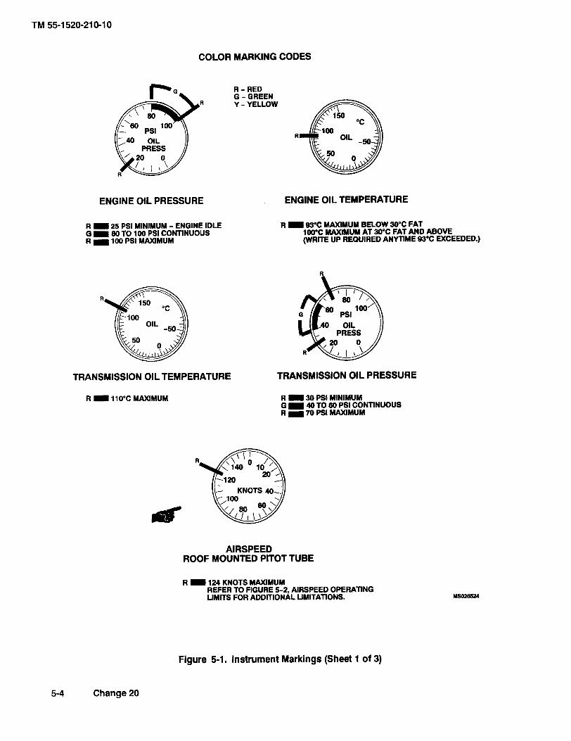
COLOR MARKING CODES
R - RED G - GREEN Y - YELLOW
ENGINE OIL PRESSURE ENGINE OIL TEMPERATURE
R 25 PSI MINIMUM - ENGINE IDLE G 80 TO 100 PSI CONTINUOUS R 100 PSI MAXIMUM
R 93OC MAXIMUM BELOW 30°C FAT 100'C W M U M AT 30'C FAT AND ABOVE (WRITE UP REQUIRED ANYTIME 93°C EXCEEDED.)
PRESS
TRANSMISSION OIL TEMPERATURE TRANSMISSION OIL PRESSURE
R 30 PSI MINIMUM G 40 TO 80 PSI CONTINUOUS R 70 PSI MAXIMUM
AIRSPEED ROOF MOUNTED PlTOT TUBE
R 124 KNOTS MAXIMUM REFER TO FIGURE 5 2 , AIRSPEED OPERATING LIMITS FOR ADDITIONAL LIMITATIONS.
Figure 5-1. Instrument Markings (Sheet 1 of 3)
5-4 Change 20

CHAPTER 7
Performance Data
SECTION I. INTRODUCTION
7-1. Purpose. The purpose of this chapter is to provide performance data. Regular use of this information will enable you to receive maximum safe utilization from the helicopter. Although maximum performance is not al- ways required, regular use of this chapter is recom- mended for the following reasons:
a. Knowledge of your performance margin will allow you to make better decisions when unexpected conditions or alternate missions are encountered.
b. Situations requiring maximum performance will be more readily recognized.
c. Familiarity with the data will allow performance to be computed more easily and quickly.
d. Experience will be gained in accurately esti- mating the effects of variables for which data are not presented.
NOTE
Chapter 7 provides information for the UN-1 H equipped with metal main rotor blades and chapter 7.1 provides data for the UH-1 H equipped with CMRB. The information pro- vided in this chapter is primarily intended for mission planning and is most useful when planning operations in unfamiliar areas or at extreme conditions. The data may also be used to revise mission planning in flight, to establish unit or area standing operating pro- cedures, and to inform ground commanders of performancelrisk tradeoffs. Tabular hover performance and power available data is pre- sented on pages 7-52, 7-54, 7-55, and 7-56.
7-2. Chapter 7 Index Deleted
NOTE Tabular hover performance and power available data is presented beginning on page 7-52. That data may be used in lieu of Figures 7-2 and 7-3 or Figure and 7.1-2 and 7.1-3 to obtain maximum hover weight, torque required to hover, and maximum calibrated torque available. The data for operation with CMRB presented in chapter 7.1 reflects an update in torque available and airspeed calibration. That update is based on more recent test data than the basis used in this chapter for operation with metal rotor blades. Thus some of the difference between the performance values shown in these two chapters is due to the difference in data basis. Update of the data for metal rotor blades to the more recent test data basis will be provided in an upcoming change.
7-3. General The data presented covers the maximum range of conditions and performance that can reason- ably be expected. In each area of performance, the ef- fects of altitude, temperature, gross weight, and other parameters relating to that phase of flight are presented. In addition to the presented data, your judgment and experience will be necessary to accurately obtain perfor- mance under a given set of circumstances. The condi- tions for the data are listed under the title of each chart. The effects of different conditions are discussed in the text. Where practical, data are presented at conservative conditions. However NO GENERAL CONSERVATISM HAS BEEN APPLIED. All performance data presented are within the applicable limits of the helicopter.
7-4. Limits Applicable limits are shown on the charts. Performance generally deteriorates rapidly beyond lim- its. If limits are exceeded, minimize the amount and time. Enter the maximum value and time above limits on DA Form 2408-13 so proper maintenance action can be tak- en.
7-5. Use of Charts
a. Chart Explanation. The first page of each sec- tion describes the chart(s) and explains its uses.
b. Shading. Shaded areas on charts indicate pre- cautionary or time limited operation.
c. Reading the Charts. The primary use of each chart is given in an example to help you follow the route through the chart. The use of a straight edge (ruler or page edge) and a hard fine point pencil is recommended to avoid cumulative errors. The majority of the charts provide a standard pattern for use as follows: enter first variable on top left scale, move right to the second vari- able, reflect down at right angles to the third variable, reflects left at right angles to the fourth variable, reflect down, etc. until the final variable is read out at the final scale.
NOTE An example of an auxiliary use of the charts referenced above is as follows:Although the hover chart is primarily arranged to find torque required tohover, by entering torque available as required, maximum skid height for hovercan also be found. In general, any single variable can be found if all othersare known. Also, the tradeoffs between two vari- ables can be found. For example,at a given pressure altitude, you can find the maximum gross weight capabilityas free air temperature changes.
d. Dashed Line Data. Data beyond conditions for which tests were conducted are shown as dashed lines.
7-6. Data Basis The type of data used is indicated at the bottom of each performance chart under DATA BA- SIS. The applicable report and date are also given. The data provided generally is based on one of four catego- ries:
a. Flight Test Data. Data obtained by flight test of the aircraft by experienced flight test personnel at precise conditions using sensitive calibrated instruments.
b. Derived From Flight Test. Flight test data ob- tained on a similar rather than the same aircraft and series. Generally small corrections will have been made.
c. Calculated Data. Data based on tests, but not on flight test of the complete aircraft.
d. Estimated Data. Data based on estimates us- ing aerodynamic theory or other means but not verified by flight test.
7-7. Specific Conditions The data presented are ac- curate only for specific conditions listed under the title of each chart. Variables for which data are not presented, but which may affect that phase of performance, are discussed in the text. Where data are available or rea- sonable estimates can be made, the amount that each variable affects performance will be given.
7-2 Change 5

SECTION IV. TAKEOFF
7-20. Description. The takeoff chart (Figure 7-5) shows the distances to clear various obstacle heights, based upon several hover height capabilities. The upper chart grid presents data for climbout at a constant INDI- CATED airspeed. The two lower grids present data for climbouts at various TRUE airspeeds. Figure 7-5, sheet 1, is based upon level acceleration technique, sheet 2 is based upon a climb and acceleration from a 3 foot skid height and sheet 3 is based upon a level acceleration from a 15-foot skid height.
NOTE The hover heights shown on the chart are only a measure of the aircraft's climb capability and do not imply that a higher than nor- mal hover height should be used during the actual takeoff.
7-21. Use of Charts. The primary use of takeoff charts is illustrated by examples. The main consideration for
takeoff performance is the hover skid height capability, which includes the effects of pressure altitude, free air temperature, gross weight, and torque. Hover height ca- pability is determined by use of the hover charts, (Figure 7-3). A hover check can be made to verify the hover capability. If winds are present, the hover check may disclose that the helicopter can actually hover at a great- er skid height than the calculated value, since the hover chart is based upon calm wind conditions.
7-22. Conditions.
a. Wind. The takeoff chart is based upon calm wind conditions. Since surface wind velocity and direc- tion cannot be accurately predicted, all takeoff planning should be based upon calm wind conditions. Takeoff into any prevailing wind will improve the takeoff performance.
b. Power Settings. All takeoff performance data are based upon the torque used in determining the hover capabilities in Figure 7-3.
Change 20 74.1/(74.2 blank)


SECTION V. CRUISE
7-23. Description. The cruise charts (Figure 7-6 sheets 1 through 24) show the torque pressure and en- gine rpm required for level flight at various pressure alti- tudes airspeeds gross weights and fuel flows.
NOTE The cruise charts are basically arranged by FAT groupings. Figure 7-6, sheets 1 through 24 are based upon operation with clean con- figuration. Each chart has a dashed line that represents a ten square foot equivalent flat plate drag area. This allows quick determina- tion of Delta PSI for other than clean configu- rations.
7-24. Use of Charts.
Cruise flight is restricted to 319 to 324 Ro- tor RPM (6500 to 6600 Engine RPM.). Cruise at 324 Rotor16600 Engine RPM is recommended. The cruise chart data for true airspeeds above 40 KTAS is based on 314 Rotor16400 Engine RPM. Until the cruise charts are revised performance planning shall be accomplished using the procedures and torque corrections from
I Table 7-1. These restrictions do not apply when composite main rotor blades (CB) are installed.
The primary use of the charts is illustrated by the exam- ples provided in Figure 7-6. The first step for chart use is to select the proper chart, based upon the planned drags configuration, pressure altitude and anticipated free air temperature; refer to Chapter 7 index (paragraph 7-2). Normally, sufficient accuracy can be obtained by selecting the chart nearest to the planned cruising alti- tude and FAT, or the next higher altitude and FAT. If greater accuracy is required, interpolation between alti- tudes and/or temperatures will be required. You may enter the charts on any side: TAS, IAS, torque pressure, or fuel flow, and then move vertically or horizontally to the gross weight, then to the other three parameters. Maxi- mum performance conditions are determined by enter- ing the chart where the maximum range or maximum endurance and rate of climb lines intersect the appropri- ate gross weight; then read airspeed, fuel flow and PSI
torque pressure. For conservatism, use the gross weight at the beginning of cruise flight. For greater accuracy on long flights it is preferable to determine cruise informa- tion for several flight segments in order to allow for de- creasing fuel weights (reduced gross weight). Estimated performance data is presented for hover (KTAS =0) in Figure 7-6, however, the hover performance data pre- sented in figure 7-3 is more accurate and should be used in planning critical hover performance. The following pa- rameters contained in each chart are further explained as follows:
a. Airspeed, True and indicated airspeeds are presented at opposite sides of each chart. On any chart, indicated airspeed can be directly converted to true air- speed (or vice versa) by reading directly across the chart without regard for other chart information. Maximum per- missible airspeed (VNE) limits appear on some charts. If no line amears VNE is above the limits of the chart. . .
b. Torque Pressure (PSI). Since pressure altitude and temperature are fixed for each chart torque pres- sures vary according to gross weight, airspeed and bleed air on or off. See paragraph 7-15. for effect of bleed air heater and deice.
NOTE Torque available values determined are not limits. Any torque which can be achieved, without exceeding engine, transmission, or other limits, may be used.
c. Fuel Flow. Fuel flow scales are provided oppo- site the torque pressure scales. On any chart, torque pressure may be converted directly to fuel flow without regard for other chart information. All fuel flows are pre- sented for bleed air heater and.deice off. Add two percent fuel flow (about 14 Iblhr) for heater on and increase fuel flow three percent (approximately 21 Ibihr) for deice on. If both are operating, add five percent fuel flow (about 35 Iblhr) to chart values.
d. Maximum Range. The maximum range lines indicate the combinations of weight and airspeed that will produce the greatest flight range per gallon of fuel under zero wind conditions. When a maximum range condition does not appear on a chart it is because the maximum range speed is beyond the maximum permissible speed O/NE); in such cases, use VNE cruising speed to obtain maximum range.
Change 17 7-5

e. Maximum Endurance and Rate of Climb. The 7-25. Conditions. The cruise charts are based upon maximum endurance and rate of climb lines indicate the operations at 324 rotorl6600engine rpm below40 KTAS airspeed for minimum torque pressure required to main- and 314 rotor16400 engine rpm for true airspeeds above tain level flight for each gross weight FAT and pressure 40 knots. With the rotor blade erosion protection coating altitude. Since minimum torque pressure will provide and polyurethane tape installed, add 2 psi to the torque minimum fuel flow maximum flight endurance will be required obtained from Figure 7-6. obtained at the airspeeds indicated.
SECTION VI. DRAG
7-26. Description. The drag chart (Figure 7-7, Sheet 1 of 2) shows the authorized configuration or the equiva- lent flat plate drag area changes for additional aircraft modifications. There is no increase in drag with cargo doors fully open. The upper left portion of Figure 7-7 (Sheet 2 of 2) presents drag areas of typical external loads as a function of the load frontal area. The balance of the charts shows the additional torque required in level flight due to the increase in drag caused by external loads, aircraft modifications or authorized configura- tions. The IR Scoup Suppressor has adrag of two square feet.
torque it is necessary to know the drag area change the true airspeed the pressure altitude and the free air tem- perature. Enter at the known drag area change, move right to TAS move down to pressure altitude move left to FAT then move down and read change in torque. In addition, by entering the chart in the opposite direction, drag area change may be found from a known torque change. This chart is used to adjust cruise charts for appropriate torque and fuel flow due to equivalent flat plate drag area change (AF). For frontal areas exceeding values shown on Figure 7-7 (Sheet 2 of 2) use a smaller value and multiply (e.g. 36 sq. ft. = 9 sq. ft. x 4).
7-27. Use of Chart. The primary use of the chart is 7-28. Conditions. The drag chart is based upon 314 illustrated by the example. To determine the change in rotor16400 engine rpm.
SECTION VII. CLIMB-DESCENT DELETED
7-6 Change 20

SECTION VIII. FUEL FLOW DELETED
Change 20 7-7

Table 7-1. Torque Correction (Sheet 1 of 4) -
To determine cruise performance data for 324 Rotor/6600 Engine RPM at speeds above 40 KTAS, follow the instructions in paragraph 7-24 except:
a. Add appropriate torque correction from this table to the calibrated torque required values determined from the intersection of the airspeed and gross weight lines on the upper (6400 Engine RPM) portion of the cruise chart.
b. Determine fuel flow corresponding to the corrected torque required from the lower (6600 Engine RPM) portion of the cruise chart.
c. Determine continuous torque available (CONT TRQ AVAIL) and 30 minute torque available (30 MIN TRQ AVAIL) from the lower (6600 Engine RPM) portion of the cruise chart.
EXAMPLE
WANTED
Speed for Maximum Range
Calibrate Torque Required and Fuel Flow at Maximum Range
KNOWN
324 Rotor/6600 Engine RPM
Clean Configuration
FAT = -30" C
Pressure Altitude = 8000 feet
Gross Weight = 8500 pounds
Roof Mounted System
METHOD
Locate (-30°C FAT, 8000 Feet) Chart (figure 7-6 Sheet 3 of 24)
Find Intersection of 8500 LB Gr Wt Line With the Max Range Line
To Read Speed for Maximum Range:
Move Right, Read TAS = 105.3 Knot
Move Left, Read IAS = 102.3
To Read Calibrated Torque Required @ 314 Rotor/6400 Engine RPM
Move Down, Read Torque = 41.2 PSI
To Correct Torque Required for 6400 Engine RFDM
From Table for Sheet 3 (8000 Ft -30°C) @ 8500 Lb Gross Weight
For 90 KTAS, Torque Correction = 3.5 PSI
For 110 KTAS, Torque Correction = 5.7 PSI
Interpolate for 105.3 KTAS Torque Correction = 5.2 PSI
Corrected Torque Required = 41.2 PSI + 5.2 PSI = 46.4 PSI
To Determine Fuel Flow
Enter Figure 7-6, Sheet 3 of 24 At 46.4 PSI Torque:
Move Down Read Fuel Flow = 614 Lb/Hr

CRUISE CRUISE CLEAN CONFIGURATION SEA LEVEL
SEA LEVEL 2000 FEET
INDICATED PRESSURE ALTITUDE
FUEL FLOW FUEL FLOW PRESSURE ALTITUDE
- POUNDS PER HOUR A'
KlAS FUEL FLOW - POUNDS PER HOUR KTAS FUEL FLOW - POUNDS PER HOUR
KlAS
DATA BASIS: DERIVED FROM YUH-1H FLIGHT TEST, ASTA-TDR 66-04, NOVEMBER 1970 MSM3856
Figure 7-6. Cruise Chart (Sheet 1 of 24)

EXAMPLE
WANTED
CALIBRATED TORQUE REQUIRED FOR LEVEL FLIGHT, FUEL FLOW, INDICATED AIRSPEED
KNOWN
CLEAN CONFIGURATION
GROSS WEIGHT = 9000 LB
PRESSURE ALTITUDE = 5000 FEET
FAT = -30 " C
DESIRED TRUE AIRSPEED = 100 KNOTS ROOF MOUNTED SYS- TEM
METHOD (INTERPOLATE)
ENTER TRUE AIRSPEED
READ CALIBRATED TORQUE, FUEL FLOW, AND IAS ON EACH ADJACENT ALTITUDE AND/OR FAT, THEN INTERPOLATE BE- TWEEN ALTITUDE AND/OR FAT.
ALTITUDE, FEET 4000 FT 6000 FEET 5000 FEET
FAT, C -30 -30 -30
CALIBRATED 41.2 40.2 40.7 TORQUE, PSI
FUEL FLOW, LB/ 582 558 570 HR
IAS, KNOTS 104.5 100.7 102.6

CRUISE CLEAN CONRGURATION
4000 FEET 6000 FEET
INDICATED PRESSURE ALTITUDE
FUEL FLOW PRESSURE ALTITUDE
INDICATED - POUNDS PER HOUR
FUEL FLOW - POUNDS PER HOUR KTAS FUEL FLOW - POUNDS PER HOUR KlAS
DATA BASIS: DERIVED FROM YUH-1H FLIGHT TEST, ASTA-TDR 66-04, NOVEMBER 1970 Y5023857
Figure 7-6. Cruise Chart (Sheet 2 of 24)

WANTED
SPEED FOR MAXIMUM RANGE
CALIBRATE TORQUE REQUIRED AND FUEL FLOW AT MAXIMUM RANGE
SPEED FOR MAXIMUM ENDURANCE
KNOWN
CLEAN CONFIGURATION, FAT = -30°C
PRESSURE ALTITUDE = 8000 FEET,
AND GROSS WEIGHT = 8500 POUNDS
ROOF MOUNTED SYSTEM
METHOD
LOCATE (-30°C FAT, 8000 FEET) CHART
FlND INTERSECTION OF 8500 GROSS WEIGHT LlNE WITH THE MAXIMUM RANGE LINE
TO READ SPEED FOR MAXIMUM RANGE:
MOVE RIGHT, READ TAS = 105.3 KNOT AND MOVE LEFT,
READ IAS = 102.3
TO READ FUEL FLOW REQUIRED:
MOVE UP, READ FUEL FLOW = 554 LB/HR
TO READ CALIBRATED TORQUE REQUIRED:
MOVE DOWN, READ TORQUE = 41.2 PSI
FlND INTERSECTION OF 8500 LB GROSS WEIGHT LINE WITH THE MAXIMUM ENDURANCE LlNE
TO READ SPEED FOR MAXIMUM ENDURANCE
MOVE RIGHT, READ TAS = 53.9 KNOTS AND MOVE LEFT,
READ IAS = 50.5 KNOTS

DATA BASIS: DERIVED FROM YUH-1H FLIGHT TEST, ASTA-TDR 66-04, NOVEMBER 1970 MSM3858
Figure 7-6. Cruise Chart (Sheet 3 of 24)

EXAMPLE
WANTED
ADDITIONAL CALIBRATED TORQUE REQUIRED AND FUEL FLOW FOR EXTERNAL DRAG CONFIGURATION
KNOWN
DF FOR EXTERNAL DRAG CONFIGURATION (FROM FIGURE 7-7, EXAMPLE B) = 4 SQUARE FEET
GROSS WEIGHT = 8000 POUNDS
FAT = -30 " C
PRESSURE ALTITUDE = 12000 FEET
TRUE AIRSPEED = 105 KNOTS
METHOD
ENTER TRUE AIRSPEED AT 105 KNOTS AND MOVE LEFT TO 8000 POUND GROSS WEIGHT LINE. MOVE UP TO FUEL FLOW SCALE AND READ 510 LBIHR. MOVE DOWN TO CALIBRATED TORQUE SCALE AND READ 39.0 PSI. MOVE LEFT (AT 105 KNOTS) TO 10 SQ FEET DF LINE, MlOVE UP AND READ 4,O DPSI. DIVIDE 4 SQ FEET BY 10 SQ FEET = 40%. 40% OF 4.0 DPSI = 1.6 DPSI. ADD 1.6 AND 39.0 = 40.6 PSI. MOVE UP FROM TORQUE SCALE AT THIS POINT TO FUEL FLOW SCALE AND READ 537 LBIHR.

Kl AS FUEL FLOW - POUNDS PER HOUR
K ITAS FUEL FLOW - POUNDS PER HOUR
KlAS
DATA BASIS: DERIVED FROM YUH-1 H FLIGHT TEST, ASTA-TDR 66-04, NOVEMBER 1970 USa23859
Figure 7-6. Cruise Chart (Sheet 4 of 24)

CRUISE CLEAN CONFIGURATION
SEA LEVEL 2000 FEET PRESSURE ALTITUDE
FUEL FLOW 1 PRESSURE ALTITUDE
FUEL FLOW - POUNDS PER HOUR - POUNDS PER HOUR *IRSPEED
400 450 500 550 600 650 KlAS KTAS FUEL FLOW - POUNDS PER HOUR FUEL FLOW - POUNDS PER HOUR
DATA BASIS: DERIVED FROM YUH-1H FLIGHT TEST, ASTA-TDR 66-04, NOVEMBER 1970 ~S(n3880
Figure 7-6. Cruise Chart (Sheet 5 of 24)

DATA BASIS: DERIVED FROM YUH-1H FLIGHT TEST, ASTA-TDR 66-04, NOVEMBER 1970 MS023861
Figure 7-6. Cruise Chart (Sheet 6 of 24)

CRUISE CLEAN CONFIGURATION
8000 FEET 1 WOO FEET PRESSURE ALTITUDE PRESSURE ALTITUDE
FUEL FLOW FUEL FLOW - POUNDS PER HOUR - POUNDS PER HOUR
Kl AS KTAS FUEL FLOW - POUNDS PER HOUR KlAS
FUEL FLOW - POUNDS PER HOUR
DATA BASIS: DERIVED FROM YUH-1H FLIGHT TEST, ASTA-TDR 66-04, NOVEMBER 1970 ~S023B(12
Figure 7-6. Cruise Chart (Sheet 7 of 24)

KlAS FUEL FLOW - POUNDS PER HOUR KTAS FUEL FLOW - POUNDS PER HOUR
KlAS
DATA BASIS: DERIVED FROM YUH-1H FLIGHT TEST, ASTA-TDR 66-04, NOVEMBER 1970 MS023863
Figure 7-6. Cruise Chart (Sheet 8 of 24)

CRUISE CLEAN CONFIGURATION
SEA LEVEL PRESSURE ALTITUDE
FUEL FLOW - POUNDS PER HOUR AIRSPEED
KlAS KTAS FUEL FLOW - POUNDS PER HOUR KlAS
FUEL FLOW - POUNDS PER HOUR
DATA BASIS: DERIVED FROM YUH-1H FLIGHT TEST, ASTA-TDR 66-04, NOVEMBER 1970 US023864
Figure 7-6. Cruise Chart (Sheet 9 of 24)

CRUISE CLEAN CONFIGURATION
4000 FEET 6000 FEET
INDICATED PRESSURE ALTITUDE
FUEL FLOW El PRESSURE ALTITUDE
FUEL FLOW - POUNDS PER HOUR - POUNDS PER HOUR
Kl AS FUEL FLOW - POUNDS PER HOUR KTAS FUEL FLOW - POUNDS PER HOUR
KlAS
DATA BASIS: DERIVED FROM YUH-1H FLIGHT TEST, ASTA-TDR 66-04, NOVEMBER 1970 M S O ~ B ~ ~
Figure 7-6. Cruise Chart (Sheet 10 of 24)

CRUISE CLEAN CONFIGURATION
8000 FEET 1 0000 FEET
INDICATED PRESSURE ALTITUDE PRESSURE ALTITUDE
FUEL FLOW TRUE FUEL FLOW AIRSPEED - POUNDS PER HOUR AIRSPEED - POUNDS PER HOUR
Kl AS KTAS FUEL FLOW - POUNDS PER HOUR KlAS
FUEL FLOW - POUNDS PER HOUR
DATA BASIS: DERIVED FROM YUH-1H FLIGHT TEST, ASTA-TDR 66-04, NOVEMBER 1970 Y S D Z ~ ~ ~ S
Figure 7-6. Cruise Chart (Sheet 11 of 24)

CRUISE CLEAN CONFIGURATION
12000 FEET 14000 FEET
INDICATED PRESSURE ALTITUDE PRESSURE ALTITU DE
AIRSPEED FUEL FLOW TRUE FUEL FLOW
- POUNDS PER HOUR AIRSPEED - POUNDS PER HOUR AIRSPEED
KlAS FUEL FLOW - POUNDS PER HOUR KTAS FUEL FLOW - POUNDS PER HOUR
KlAS
DATA BASIS: DERIVED FROM YUH-1H FUGHTTEST, ASTA-TDR 86-04, NOVEMBER 1970 MSOMBs7
Figure 7-6. Cruise Chart (Sheet 12 of 24)

CRUISE CLEAN CONFIGURATION
SEA LEVEL 2000 FEET
INDICATED PRESSURE ALTITUDE PRESSURE ALTITUDE INMATED
AIRSPEED
Kl AS FUEL FLOW - POUNDS PER HOUR KTAS FUEL FLOW - POUNDS PER HOUR
Kl AS
DATA BASIS: DERIVED FROM YUH-1H FLIGHT TEST, ASTA-TDR 68-04, NOVEMBER 1970 Ys023888
Figure 7-6. Cruise Chart (Sheet 13 of 24)
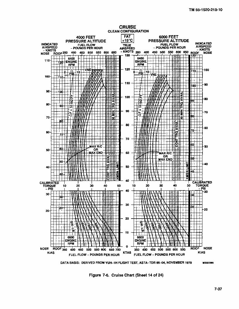
CRUISE CLEAN CONFIGURATION
4000 FEET 6000 FEET
INDICATED PRESSURE ALTITUDE PRESSURE ALTITUDE INDlcAnD
AIRSPEED
KlAS KTAS FUEL FLOW - POUNDS PER HOUR
KlAS FUEL FLOW - POUNDS PER HOUR
DATA BASIS: DERIVED FROM YUH-1H FLIGHT TEST, ASTA-TDR 66-04, NOVEMBER 1970 M W ? ~ W
Figure 7-6. Cruise Chart (Sheet 14 of 24)

CRUISE CLEAN CONFIGURATION
8000 FEET 10000 FEET PRESSURE ALTITUDE
FUEL FLOW - POUNDS PER HOUR
KlAS KTAS FUEL FLOW - POUNDS PER HOUR Kl AS
FUEL FLOW - POUNDS PER HOUR
DATA BASIS: DERIVED FROM YUH-1 H FLIGHT TEST, ASTA-TDR 66-04, NOVEMBER 1970 MSM3870
Figure 7-6. Cruise Chart (Sheet 15 of 24)

CRUISE CLEAN CONFlGURATlON
12000 FEET 14000 FEET
Kl AS KTAS FUEL FLOW - POUNDS PER HOUR KlAS
FUEL FLOW - POUNDS PER HOUR
DATA BASIS: DERIVED FROM YUH-1 H FLIGHT TEST, ASTA-TDR 66-04, NOVEMBER 1970 ~~1
Figure 7-6. Cruise Chart (Sheet 16 of 24)

CRUISE CLEAN CONFIGURATION
SEA LEVEL 2000 FEET
INDICATED PRESSURE ALTITUDE PRESSURE ALTITUDE lNDWw
KlAS FUEL FLOW - POUNDS PER HOUR KTAS FUEL FLOW - POUNDS PER HOUR
KlAS
DATA BASIS: DERIVED FROM YUH-1H FLIGHT TEST, ASTA-TDR 68-04, NOVEMBER 1970 w3oza72
Figure 7-6. Cruise Chart (Sheet 17 of 24)

CRUISE CLEAN CONFIGURATION
4000 FEET 6000 FEET
INDICATED PRESSURE ALTITUDE
FUEL FLOW PI PRESSURE ALTITUDE
TRUE AIRSPEED
KlAS FUEL FLOW - POUNDS PER HOUR KTAS FUEL FLOW - POUNDS PER HOUR
KlAS
DATA BASIS: DERIVED FROM WH-1H FLIGHT TEST, ASTA-TDR 68-04, NOVEMBER 1970 w1SOP873
Figure 7-6. Cruise Chart (Sheet 18 of 24)

CRUISE CLEAN CONFIGURATION
8000 FEET 1 0000 FEET
INDICATED PRESSURE ALTITUDE
FUEL FLOW
FUEL FLOW - POUNDS PER HOUR
DATA BASIS: DERIVED FROM YUH-1 H FLIGHT TEST, ASTA-TDR 66-W, NOVEMBER 1970 8!3023814
Figure 7-6. Cruise Chart (Sheet 19 of 24)

CRUISE CLEAN CONRGURATION
12000 FEET 14000 FEET PRESSURE ALTITUDE
FUEL FLOW FUEL FLOW - POUNDS PER HOUR - POUNDS PER HOUR
Kl AS KTAS FUEL FLOW - POUNDS PER HOUR KlAS
FUEL FLOW - POUNDS PER HOUR
DATA BASIS: DERIVED FROM WH-1H FLIGHT TEST, ASTA-TOR 66-04, NOVEMBER 1970 Ma23975
Figure 7-6. Cruise Chart (Sheet 20 of 24)

CRUISE CLEAN CONFIGURATION
SEA LEVEL 2000 FEET
INDICATED PRESSURE ALTITUDE
FUEL FLOW El PRESSURE ALTITUDE INDICATED
- POUNDS PER HOUR
Kl AS KTAS FUEL FLOW - POUNDS PER HOUR
KlAS FUEL FLOW - POUNDS PER HOUR
DATA BASIS: DERIVED FROM YUH-1H FLIGHTTEST, ASTA-TDR 68-04, NOVEMBER 1970 Y5023876
Figure 7-6. Cruise Chart (Sheet 21 of 24)
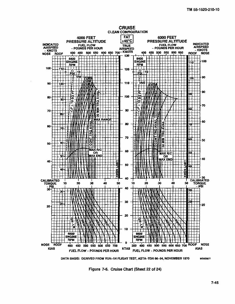
CRUISE CLEAN CONFIGURATION
4000 FEET 6000 FEET
INDICATED PRESSURE ALTITUDE p] PRESSURE ALTITUDE
AIRSPEED
KlAS FUEL FLOW - POUNDS PER HOUR KTAS FUEL FLOW - POUNDS PER HOUR
KlAS
DATA BASIS: DERIVED FROM YUH-1H FUGHT TEST, ASTA-TDR 86-04, NOVEMBER 1970 M S Q 2 3 a n
Figure 7-6. Cruise Chart (Sheet 22 of 24)

CRUISE CLEAN CONFIGURATION
8000 FEET 10000 FEET PRESSURE ALTITUDE PI PRESSURE ALTITUDE
INDICATED
KlAS KTAS FUEL FLOW - POUNDS PER HOUR
KlAS FUEL FLOW - POUNDS PER HOUR
DATA BASIS: DERIVED FROM YUH-1 H FLIGHT TEST, ASTA-TDR 66-04, NOVEMBER 1970 M-8
Figure 7-6. Cruise Chart (Sheet 23 of 24)

CRUISE CLEAN CONFIGURATION
12000 FEET 14000 FEET
INDICATED PRESSURE ALTITUDE
FUEL FLOW PI PRESSURE ALTITUDE wDICATED
TRUE FUEL FLOW
/ A t 1 I I I Y I I I I I I 1 . 1
CALIBRATED I , ,, " I ' ' 1 " ' I I ' r'dAllbkATED
TOROUE 10 20 30 40 50 10 20 30 40 50 TORQUE
KlAS KTAS FUEL FLOW - POUNDS PER HOUR
KlAS FUEL FLOW - POUNDS PER HOUR
DATA BASIS: DERIVED FROM YUH-1 H FLIGHT TEST, ASTA-TDR 66-04, NOVEMBER 1970 US023879
Figure 7-6. Cruise Chart (Sheet 24 of 24)

DRAG
EXAMPLE A
WANTED
AF-SQ FT
CLEA CONFIGU ATlON I I +AsEuN$ I CARGO MIRROR
NOTE: THE IR SCOUP SUPPRESSOR HAS A DRAG OF TWO SQUARE FEET
CHANGE IN TORQUE REQUIRED DUE TO EQUIVALENT FLAT PLATE DRAG AREA CHANGE (hF) FROM CLEAN (BASELINE) CONFIGURATION TO AN M-59 SUBSYSTEM CONFIGURATION a AF DRAG AREA CHANGE = 12 SQ. FT. TRUE AIRSPEED = 120 KNOTS PRESSURE ALTITUDE = SEA LEVEL FAT = 0°C a
METHOD
ENTERDRAGAREACHANGE MOVE RIGHT TO TRUE AIRSPEED MOVE DOWN TO PRESSURE ALTITUDE MOVE LEFT TO FREE AIR TEMPERATURE M O M DOWN, READ CHANGE IN TORQUE = 10.3 PSI
EXAMPLE B
WANTED
INCREASE IN DRAG AREA DUE TO EXTERNAL CARGO
KNOWN
SHAPE OF EXTERNAL LOAD = CYUNDER FRONTAL AREA OF EXTERNAL LOAD = 6.8 SQ. FT.
METHOD
ENTER CHART AT SYMBOL FOR CYUNDER MOVE DOWN TO 6.8 SQ. FT. MOVE RIGHT AND READ INCREASED DRAG AREA = 4.0 SQ. FT.
Figure 7-7. Drag Chart (Sheet 1 of 2)
7-48 Change 20

EXTERNAL LOAD- EFFECT DRAG
TORQUE CHANGE - PSI
DATA BASIS: CALCULATED DATA
Figure 7-7. Drag Chart (Sheet 2 of 2)

Figure 7-8. Climb-Descent Chart Deleted
7-50 Change 20

Figure 7-9. Idle Fuel Flow Chart Deleted
Change 20 7-51

Use of the TABULAR CHARTS is illustrated by the following examples:
I TABULAR PERFORMANCE DATA Pages 7-52 through 7-56
KNOWN:
Pressure Altitude (PA) = 1000 FEET
Free Air Temperature (FAT) = t25
WANTED:
Maximum GW for Hover OGE.
Torque Required for Hover OGE.
Torque Required for Hover IGE (2 FEET).
METHOD:
1. Enter PA at 1,000 Feet, and Move Right to t25 C.
2. The Top Number (912) is the Maximum GW to Hover OGE. (= 9,120 POUNDS.)
3. The Middle Number (45) is the Torque required to Hover OGE at the Maximum GW to Hover OGE (9,120). (= 45 PSI.)
4. The Bottom Number (37) is the Torque required at a 2 Foot Hover at the Maximum GW to Hover OGE (9,120). (= 37 PSI.)
TABULAR PERFORMANCE DATA (Page C-5)
KNOWN:
Pressure Altitude (PA) = 1000 FEET
Free Air Temperature (FAT) = t25
WANTED:
Maximum Torque available (30 MINUTES).
METHOD:
1. Enter PA at 1,000 Feet, and Move Right to t20 C and +30 C.
2. Interpolate between 48.0 and 42.7 PSI, the Maximum Torque available will be between. (45.4)
3. Torque Values outlined in Tabular Data are Calibrated Values and should be converted to indicated before use in the cockpit.
7-52 Change 20

Change 20 7-53

MU
IMU
M B
OV
EI(
rW
1Gm
AK
O T
OW
UE
llsQ
Ull
lED
m
VEL
SU
WA
Ce
CA
LM
WIN
D ~
~
~R
Or
mI
~E
Nc
iw
gl
PP
M
Q O
GE
-PSI
50
50
50
50
50
50
Q
IGE-PSI l
ll
ll
li
42
42
42
41
41
40


hlAXIMUM TORQUE AVAILABLE-30 MINUTE LIhllT ANTI-ICE OFF BLEED AIR HEATER OFT 324 ROTOR 1 6690 ENGINE RPM
7-56 Change 20

c. Helicopter Variations. Variations in perfor- 7.1-10. Definitions of Abbreviations. mance between individual helicopters are known to ex- ist; however, they are considered to be small and cannot a. Unless otherwise indicated, abbreviations and
be individually accounted for. symbols used in this manual conform to those estab- lished in Military Standard MIL-STD-12, which is ~eriodi-
d, Instrument Variation. The data shown in the call)' revised t d reflect current changes in abbreviations performance charts do not account for instrument inac- Usage. curacies or malfunctions. b. Capitalization and punctuation of abbrevia-
e. Types of Fuel. All flight performance data is based on JP-4 fuel. The change in fuel flow and torque available, when using JP-5, JP-8, aviation gasoline or any other approved fuels, is insignificant.
7.1-9. Performance Discrepancies. Regular use of this chapter will allow you to monitor instruments and other helicopter systems for malfunction, by comparing actual performance with planned performance. Knowl- edge will also be gained concerning the effects of vari- ables for which data are not provided, thereby increasing the accuracy of performance predictions.
tions varies depending upon the content in which they are used. In general, lower case abbreviations are used in text material, whereas abbreviations used in charts and illustrations appears in full capital letters. Periods do not usually follow abbreviations; however, periods are used with abbreviations that could be mistaken for whole words if the period were omitted.
7.1 -1 1. Temperature Conversion. The temperature conversion chart (Figure 29-1) is arranged so that de- grees Celsius can be converted quickly and easily by reading Celsius and looking directly across the charts for the Fahrenheit equivalent and vice versa.
SECTION II. TORQUE AVAILABLE
7.1 -1 2. Description. The torque available charts (Fig- ure 29-2) show the effects of altitude and temperature on engine torque
7.1-13. Chart Differences. Both pressure altitude and FAT affect engine power production. Figure 29-2 shows power available data at 30-minute power ratings in terms of calibrated and indicated torque. Note that the power output capability of the T53-L-13 engine can exceed the transmission structural limit (50 psi calibrated torque un- der certain conditions.
a. Figure 29-2 (sheet 1) is applicable for maxi- mum power, 30-minute operation at 324 rotor16600 en- gine rpm with particle separator installed.
b. Figure 29-2 (sheet 2) is applicable for maxi- mum power, 30-minute operation at 314 rotor16600 en- gine rpm with particle separator installed.
c. Prolonged IGE hover may increase engine in- let temperature as much as 1 O0C, therefore a 10" higher FAT must be used to correct for this condition
d. If the IR Scoup Suppressor is installed on the aircraft, subtract one psi for the torque values obtained from Figure 29-2, sheets 1 and 2.
7.1-14. Use of Charts. The primary use of the torque available charts is illustrated by the examples in general, to determine the maximum power available, it is neces- sary to know the pressure altitude and temperature. The calibration factor (Data Plate Torque), obtained from the engine data plate or from the engine acceptance re- cords, is the indicated torque pressure at 1125 ft-lbs actual output shaft torque, and is used to correct theerror of individual engine torque indicating system.
NOTE Torque available values determined are not limits. Any torque which can be achieved, without exceeding engine, transmission, or other limits, may be used.
7.1-15. Conditions. The torque available charts (Fig- ure 29-2) are based upon speeds of 324 rotor16600 en- gine rpm, 314 rotor16400 engine rpm and grade JP-4 fuel. The use of aviation gasoline will not influence en- gine power. All torque available data are presented for I bleed air heater and deice off. Decrease torque available 1.4 psi for heater on and 2.1 for deice on; decrease torque available 3.5 psi if both bleed air heater and deice are operating.
Change 20 7.1-3
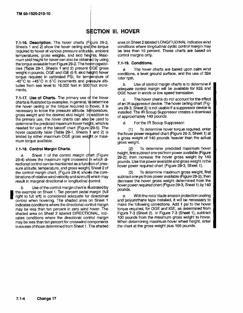
7.1-16. Description. The hover charts Sheets 1 and 2) show the hover ceiling a required to hover at various pressure altit temperatures, gross weights, and skid mum skid height for hover can also be o the torque available from Figure 29-2. T ities (Table 29-1, Sheets 1 and 2) presen weight in pounds, OGE and IGE (5 ft. skid torque required in calibrated PSI, for te -40°C to +4S0C in 5°C increments a tudes from sea level to 16,000 feet i ments.
7.1-17. Use of Charts. The primary use charts is illustrated by examples. In general, the hover ceiling or the torque required necessary to know the pressure altitude, gross weight and the desired skid height. the primary use, the hover charts can determine the predicted maximum needed for use of the takeoff hover capability table (Table limited by either maximum mum torque available.
7.1-18. Control Margin Charts. I a. Sheet 1 of the control margin
sure altitude,
b. Use of the control margin chart is illustrated by
I the example on Sheet 1. Ten percent pedal margin (full right to full left) is considered adequate for directional control when hovering. The shaded area on Sheet 1 indicates conditions where the directional control margin may be less than ten percent in zero wind hover. The shaded area on Sheet 2 labeled DIRECTIONAL, indi- cates conditions where the directional control margin may be less than ten percent for crosswind components in excess of those determined from Sheet 1. The shaded
area on Sheet 2 labeled LONGITUDINAL indicates wind conditions where longitudinal cyclic control margin may be less than 10 percent. These charts are based on control margins only.
7.1-19. Conditions.
a. The hover charts are based upon calm wind conditions, a level ground surface, and the use of 324 rotor rpm.
b. Use of control margin charts is to determine if adequate control margin will be available for IGE and OGE hover in winds or low speed translation.
c. The hover charts do not account for the effect of an IR suppressor device. The hover ceiling chart (Fig- ure 29-3, Sheet 2) is not usable if a suppressor device is installed. The IR Scoup Suppressor creates a download of approximately 140 pounds.
d. For the IR Scoup Suppressor:
(1) To determine hover torque required, enter the hover power required chart (Figure 29-3, Sheet 1) at a gross weight of 140 pounds heavier than the actual gross weight.
(2) To determine predicted maximum hover height, first subtract one psi from power available (Figure 29-2); then increase the hover gross weight by 140 pounds. Use this power available and gross weight in the hover power required chart (Figure 29-3, Sheet 1).
(3) To determine maximum gross weight, first subtract one psi from power available (Figure 29-2); then decrease the hover gross weight determined from the hover power required chart (Figure 29-3, Sheet 1) by 140 pounds.
e, With the rotor blade erosion protection coating and polyurethane tape installed, it will be necessary to make the following corrections. Add 1 psi to the hover torque required, for OGE and IGE, as determined from Figure 7-3 (Sheet 2). In Figure 7-3 (Sheet I), subtract 100 pounds from the maximum gross weight to hover. When determining maximum hover wheel height, enter the chart at the gross weight plus 100 pounds.
7.1-4 Change 17

SECTION V. CRUISE
7.1-23. Description. The cruise charts (Figure 29-6, sheets 1 through 24) are based upon operation with a clean configuration. They show the torque pressure and engine rpm required for level flight at various pressure altitudes, airspeeds, gross weights, and fuel flows.
NOTE
Each chart has a dashed line that represents a 10 square-foot equivalent flat plate drag area. This allows quick determination of delta PSI for other than clean configurations.
7.1-24. Use of Charts. The primary use of the cruise charts is illustrated by the examples provided in Figure 29-6. The first step for chart use is to select the proper chart, based upon the pressure altitude and anticipated free air temperature. (Refer to Chapter 7.1 index, para- graph 7.1 -2. Normally sufficient accuracy can be ob- tained by selecting the chart nearest to the planned cruis- ing altitude and FAT, or the next higher altitude and FAT. If greater accuracy is required, interpolation between altitudes and/or temperatures will be required. You may enter the charts on any side (TAS, IAS, torque pressure, or fuel flow) then move vertically or horizontally to the gross weight, and then to the other three parameters. Determine maximum performance conditions by enter- ing the chart where the maximum range or maximum endurance and rate of climb lines intersect the appropri- ate gross weight, then read airspeed, fuel flow and PSI torque pressure. For conservatism, use the gross weight at the beginning of cruise flight. For greater accuracy on long flights it is preferable to determine cruise informa- tion for several flight segments in order to allow for de- creasing fuel weights reduced gross weight). Estimated performance data is presented for hover (KTAS = 0) in Figure 29-6; however, the hover performance data pre- sented in Figure 29-3 is more accurate and should be used in planning critical hover performance. The follow- ing parameters contained in each chart are further ex- plained as follows:
a. Airspeed. True and indicated airspeeds are presented at opposite sides of each chart. On any chart, indicated airspeed can be converted to true airspeed (or vice versa) by reading directly across the chart without regard for other chart information. Maximum permissible
airspeed (VNE) limits appear on some charts. If no line appears, VNE is above the limits of the chart.
b. Torque Pressure (PSI). Since pressure altitude and temperature are fixed for each chart, torque pres- sures vary according to gross weight, airspeed and bleed air operation. See paragraph 7.1-15. for effect of bleed air heater and deice.
NOTE Torque available values determined are not limits. Any torque which can be achieved, without exceeding engine, transmission, or other limits, may be used.
c. Fuel Flow. Fuel flow scales are provided oppo- site the torque pressure scales. On any chart, torque pressure may be converted directly to fuel flow without regard for other chart information. All fuel flows are pre- sented for bleed air heater and deice off. Add 2 percent fuel flow (about 14 Ibs) for heater on and increase fuel flow 3 percent (approximately 21 Ib/hr) for deice on. If both are operating, add 5 percent fuel flow (about 35 Ib/hr) to chart values.
d. Maximum Range. The maximum range lines indicate the combinations of weight and airspeed that will produce the greatest flight range per gallon of fuel under zero wind conditions. When a maximum range condition does not appear on a chart it is because the maximum range speed is beyond the maximum permissible VNE. In such cases, use VNE cruising speed to obtain maxi- mum range.
e. Maximum Endurance and Rate of Climb. The maximum endurance and rate of climb lines indicate the airspeed for minimum torque pressure required to main- tain level flight for each gross weight, FAT and pressure altitude. Since minimum torque pressure will provide minimum fuel flow, maximum flight endurance will be obtained at the airspeeds indicated.
7.1-25. Conditions. The cruise charts are based upon operations at 324 rotor/6600 engine rpm below 40 KTAS and 314 rotor/6400 engine rpm for true airspeeds above 40 knots. With the rotor blade erosion protection coating and polyurethane tape installed, add 1 psi to the torque required obtained from Figure 29-6 for true airspeeds less than 100 KTAS. I
Change 17 7.1 -5

SECTION VI. DRAG
7.1-26. Description. The drag chart (Figure 29-7, sheet 1 of 2) shows the equivalent flat plate drag area changes for additional authorized configurations. There is no increase in drag with cargo doors fully open. The upper left portion of Figure 29-7, sheet 2 of 2, presents drag areas of typical external loads as a function of the load frontal area. The balance of the chart shows the additional torque required in level flight due to the in- crease in drag caused by external loads or aircraft modi- fications. The IR Scoop Suppressor has a drag of two square feet.
true airspeed, the pressure altitude and the free air tem- perature. Enter at the known drag area change, move right to TAS, move down to pressure aJtitude, move left to FAT, then move down and read change in torque. In addition, by entering the chart in the opposite direction, drag area change may be found from 2 known torque change. This chart is used to adjust cruise chart torque and fuel flow due to equivalent flat plate drag area change (AF). For frontal areas exceeding values shown on Figure 29-7 (sheet 2 of 2) use a smaller value and multiply, e.g. 36 sq. ft. = 12 sq. ft. X 3.
7.1 -27. Use of Chart. The primary use of the drag chart is illustrated by the example. To determine the change in 7.1-28. Conditions. The drag chart is based upon 314 torque, it is necessary to know the drag area change, the rotor/6400 engine rpm.
SECTION VII. CLIMB DELETED
Change 20

SECTION VIII. FUEL FLOW DELETED
Change 20 7.1-7

TM 55-1 520-21 0-1 0
TEMPERATURE CONVERSION CHART - AIR TEMPERATURE - O C O F
Figure 7.1-1. Temperature conversion chart
Change 8

CRUISE CLEAN CONFIGURATION
CRUISE 8000 FEET
PRESSURE ALTITUDE PRESSURE ALTITUDE FAT = 45'C
8000 FEET INDICATED wnaw NEL FLW
- W N D S PER HOUR TRM -POUNDSRSHM)R INDICATED W E E D *IIUIPEED
TOROUE FORQUE 10 20 30 40 50 10 20 30 40 50 --
Figure 7.1-6 Cruise chart (Sheet 23 of 23)
Change 8 7.1-45

DRAG
TI AF-SQ FT
I , I CLEANCONFIGU~TION (BASE LINE) I I
CARGO MIRROR
M-23 SUBSYSTEM
M-59 SUBSYSTEM
NOTE: THE IR SCOUP SUPPRESSOR HAS A DRAG OF TWO SQUARE FEET
Figure 7.1-7. Drag Chart (Sheet 1 of 2)
Change 20 7.1-46

EXAMPLE A
WANTED
CHANGE IN TORQUE REQUIRED DUET0 EQUIVALENT FLAT PLATE DRAG
AREA CHANGE (AF) FROM CLEAN (BASELINE) CONFIGURATION TO AN
M-23 SUBSYSTEM CONFIGURATION
KNOWN
AF DRAG AREA CHANGE
TRUE AIRSPEED = 120 KNOTS
PRESSURE ALTITUDE = SEA LEVEL
FAT = 0°C
METHOD
ENTER DRAG AREA CHANGE
MOVE RIGHT TO TRUE AIRSPEED
MOVE DOWN TO PRESSURE ALTITUDE
MOVE LEFT TO FREE AIR TEMPERATURE
MOVE DOWN, READ CHANGE IN TORQUE = 9 PSI
EXAMPLE B
WANTED
INCREASE IN DRAG AREA DUE TO EXTERNAL CARGO
KNOWN
SHAPE OF EXTERNAL LOAD IS A CYLINDER WITH A FRONTAL AREA OF 6.8 SQ. FT. AF
METHOD
ENTER CHART AT SYMBOL FOR CYLINDER
MOVE DOWN TO 6.8 SQ. FT.
MOVE RIGHT, READ INCREASED DRAG AREA = 4 SQ. FT.
Change 20 7.1 -47
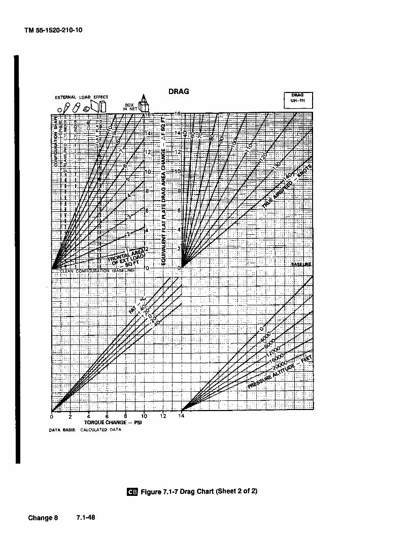
Figure 7.1-7 Drag Chart (Sheet 2 of 2)
Change 8 7.1 -48

EXAMPLE
WANTED
TlME DISTANCE AND FUEL
KNOWN
GROSS WEIGHT = 9000 POUNDS
INITIAL PRESSURE ALTITUDE = 4000 FEET
FINAL PRESSURE ALTITUDE = 10000 FEET
FAT = 17°C
METHOD
ENTER GROSS WEIGHT
MOVE UP TO INITIAL PRESSURE ALTITUDE
DETERMINE INITIAL FAT = 7°C
CALCULATE AFAT FROM STANDARD DAY FREE AIR TEMPERATURE
(ACTUAL FAT MINUS STANDARD DAY FAT) = AFAT
(17" C-7°C) = 10°C
MOVE RIGHT TO ISA + 10°C LlNE
DROP VERTICALLY, READ
DISTANCE = 2.0 NAUTICAL MILES
TlME = 2.0 MINUTES
CONTINUE DOWN TO ISA + 10°C FUEL LlNE
MOVE LEFT, READ FUEL = 23 POUNDS
REENTER GROSS WEIGHT
MOVE UP TO FINAL PRESSURE ALTITUDE
MOVE RIGHT TO ISA + 10°C LlNE
DROP VERTICALLY, READ
DISTANCE = 5.5 NAUTICAL MILES
TlME = 5.5 MINUTES
CONTINUE DOWN TO ISA + 10°C FUEL LlNE
MOVE LEFT, READ FUEL = 63 POUNDS
FINAL TlME = (5.5 - 2.0) = 3.5 MINUTES
FINAL DISTANCE = (5.5 - 2.0) = 3.5 NAUTICAL MILES
FINAL FUEL = (63 - 23) = 40 POUNDS
Change 8 7.1-49

I rn Figure 7.1-8. Climb Chart (Sheet 1 of 2) has been deleted.
Figure 7.1-8 Climb Chart (Sheet 2 of 2) has been deleted.
Figure 7.1-9. Flow Fuel Chart (Sheet 1 of 2) has been deleted.
00 Figure 7.1-10. Flow Fuel Chart (Sheet of 2) has been deleted.
Pages 7.1 -51 through 7.1-53lp.1-54 blank) have been deleted.
7.1-50 Change 20

(2) DC circuit breakers - In except for arma- ment and special equipment.
0 (3) DOME LT switch - As required.
(4) PlTOT HTR switch - OFF.
* (5) EXT LTS switches - Set as follows:
(a) ANTI COLL switch - ON.
(b) POSITION lights switches - As re- quired: STEADY or FLASH for night; OFF for day.
(6) MlSC switches - Set as follows:
(a) CARGO REL switch - OFF.
(b) WIPERS switch - OFF.
(7) CABIN HEATING switches - OFF.
(8) INST LTG switches - As required.
(9) AC POWER switches - Set as follows:
(a) PHASE switch - AC.
(b) INVTR switch - OFF.
(1 0) DC POWER switches - Set as follows:
(a) MAlN GEN switch - ON and cover down.
(b) VM selector - ESS BUS.
(c) NON-ESS BUS switch - As required.
(d) STARTER GEN switch - START.
(e) * BAT switch - ON.
* b. Ground power unit - Connect for GPU start.
0 c. Smoke gage - Check.
d. FIRE warning indicator light - Test.
e. Press to test cautionlwarning lights - Check as required.
f. Systems instruments - Check engine and transmission systems for static indications, slippage marks and ranges.
g. Center pedestal switches - Set as follows:
(1) Avionics equipment - Off; set as desired.
(2) External stores jettison handle - Check safetied.
0 (3) DlSP CONTROL panel - Check ARM1 STBYISAFE switch is SAFE; check that JE'ITISON switch is down and covered.
(4) GOV switch - AUTO.
(5) DE-ICE switch - OFF.
* (6) FUEL switches - Set as follows:
(a) MAlN FUEL switch - ON.
(b) Deleted. I (c) All other switches - OFF.
(7) CAUTION panel lights - TEST and RE- SET.
(8) HYD CONT switch - ON.
(9) FORCE TRIM switch - ON.
(10) CHIP DET switch - BOTH.
h. Flight controls-Checkfreedom of movement through full travel: center cyclic and pedals; collective pitch full down.
i. Altimeters - Set to field elevation.
* 8-22. Starting Engine.
a. Fireguard - Posted if available.
b. Rotor blades - Check clear and untied.
c. Ignition key lock switch - On.
d. Throttle- Set for start. Position the throttle as near as possible (on decrease side) to the engine idle stop.
e. Engine - Start as follows:
(1) Start switch - Press and hold; start time. Note DC voltmeter indication. Battery starts can be made when voltages less than 24 volts are indicated provided the voltage is not below 14 volts when cranking through 10 percent N1 speed.
(2) Main rotor - Check that the main rotor is turning as N1 reaches 15 percent. If the rotor is not turning abort the start.
0 (3) START FUEL switch - OFF at 40 per- cent N1.
(4) Start switch - Release at 40 percent N1 or after 40 seconds whichever occurs first. Refer to chapter 5 for starter limitations.
(5) Throttle - Slowly advance past the engine idle stop to the engine idle position. Manually check the engine idle stop by attempting to close the throttle.
Change 20 8-5

(6) N1-68 to 72 percent. Hold a very slight pressure against the engine idle stop during the check. A slight rise in N1 may be anticipated after releasing pressure on throttle.
The copilot attitude indicator should be caged and held momentarily as inverter power is applied.
f, INVTR switch - MAIN ON.
g. Engine and transmission oil pressures - Check.
h. GPU - Disconnect.
8-23. Engine Runup.
* a. Avionics - On.
* b. STARTER GEN switch - STBY GEN.
* c. Systems - Check as follows:
(1) FUEL.
(2) Engine.
(3) Transmission.
(4) Electrical.
(a) AC - 112 to 118 volts.
(b) DC - 27 volts at 26°C and above. 28 volts from 0°C to 26°C. 28.5 volts below 0°C.
* d. *RPM - 6600. As throttle is increased, the low rpm audio and warning light should be off at 61 00 to 6300 rpm.
e. Deleted.
* f. Avionics and fight instruments - Check and set as required.
NOTE HIT Checks while operating in adverse condi- tions (e.g., dust, desert, coastal beach area, dry riverbeds) may be deferred (maximum of 5 flight hours) at the discretion of the pilot in command until a suitable location is reached.
g. Health lndicator Test (HIT) Check - Perform as required. Refer to HITIEGT Log in helicopter log book. Normal HIT Check not required if utilizing in-flight HIT checks unless engine maintenance has taken place since last return flight.
8-24. Deleted.
8-25. Deleted.
8-26. Deleted.
8-27. Deleted.
8-28. Hoverpaxi Check. Perform the following checks at a hover:
* a. Engine and transmission instruments - Check.
* b. Flight Instruments - Check as required.
(1) VSI and altimeter- Checkfor indication of climb and descent.
(2) Slip lndicator - Check ball free in race.
(3) Turn needle heading indicator and magnet- ic compass - Check for turn indication left and right.
(4) Attitude Indicator - Check for indication of nose high and low and banks left and right.
(5) Airspeed Indictor - Check airspeed.
* c. , Power - Check as required. The power check is performed by comparing the indicated torque required to hover with the predicted values from perfor- mance charts.
8-29. Deleted. I
8-6 Change 17
* 8-30. Before Take-off. Immediately prior to take-off the following checks shall be accomplished.
1. RPM - 6600.
2. Systems - Check engine, transmission, elec- trical, and fuel systems indications.
3. Avionics - As required.
4. Crew passengers and mission equipment - Check.
During take-off and at any time the helicopter skids are close to the ground, negative pitch
I attitudes (nose low) of 10" or more can result in ground contact of the WSPS lower cutter.
I Forward c.g. high gross weight, high density altitude, transitional lift setting, and a tail wind increases the probability of ground contact.
8-32. Deleted.
8-33. Maximum Performance. A take-off that de- I mands maximum performance from the helicopter is
necessary because of various combinations of heavy helicopter loads limited power and restricted perfor- mance due to high density altitudes barriers that must be cleared and other terrain features. The decision to use either of the following take-off techniques must be based on an evaluation of the conditions and helicopter perfor- mance. The copilot (when available) can assist the pilot in maintaining proper rpm by calling out rpm and torque as power changes are made thereby allowing the pilot more attention outside the cockpit.
a. Coordinated Climb. Align the helicopter with the desired take-off course at a stabilized hover of approximately three feet (skid height). Apply forward cy- clic pressure smoothly and gradually while simulta- neously increasing collective pitch to begin coordinated acceleration and climb. Adjust pedal pressure as neces- sary to maintain the desired heading. Maximum torque available should be applied (without exceeding helicop- ter limits) as the helicopter attitude is established that will permit safe obstacle clearance. The climb out is contin- ued at that attitude and power setting until the obstacle is cleared. After the obstacle is cleared adjust helicopter attitude and collective pitch as required to establish a climb at the desired rate and airspeed. Continuous coor- dinated application of control pressures is necessary to maintain trim heading flight path airspeed and rate of
climb. This technique is desirable when OGE hover ca- pability exists. Take-off may be made from the ground by positioning the cyclic control slightly forward of neutral prior to increasing collective pitch.
b. Level Acceleration. Align the helicopter with the desired take-off course at a stabilized hover of approximately three feet (skid height). Apply forward cy- clic pressure smoothly and gradually while simulta- neously increasing collective pitch to begin an accelera- tion at approximately 3 to 5 feet skid height. Adjust pedal pressure as necessary to maintain the desired heading. Maximum torque available should be applied (without exceeding helicopter limits) prior to accelerating through effective transitional lift. Additional forward cyclic pres- sure will be necessary to allow for level acceleration to the desired climb airspeed. Approximately five knots prior to reaching the desired climb airspeed gradually release forward cyclic pressure and allow the helicopter to begin a constant airspeed climb to clear the obstacle. Care must be taken not to decrease airspeed during the climb out since this may result in the helicopter descend- ing. After the obstacle is cleared adjust helicopter atti- tude and collective pitch as required to establish a climb at the desired rate and airspeed. Continuous coordi- nated application of control pressures is necessary to maintain trim heading flight path airspeed and rate of climb. Take-off may be made from the ground by posi- tioning the cyclic control slightly forward of neutral prior to increasing collective pitch.
c. Deleted.
d, Comparison of Techniques. Refer to Chapter 7, Performance Data for a comparison of take-off dis- tances. Where the two techniques yield the same dis- tance over a fifty-foot obstacle the coordinated climb technique will give a shorter distance over lower ob- stacles and the level acceleration technique will give a shorter distance over obstacles higher than fifty feet. The two techniques give approximately the same distance over a fifty-foot obstacle when the helicopter can barely hover OGE. As hover capability is decreased the level acceleration technique gives increasingly shorter dis- tances than the coordinated climb technique. In addition to the distance comparison the main advantages of the level acceleration technique are: (1) it requires less or no time in the avoid area of the height velocity diagram; (2) performance is more repeatable since reference to atti- tude which changes with loading and airspeed is not required; (3) at the higher climb out airspeeds (30 knots or greater) reliable indicate airspeeds are available for accurate airspeed reference from the beginning of the climb out therefore minimizing the possibility of descent. The main advantage of the
Change 20 8-7

coordinated climb technique is that the climb angle is established early in the take-off and more distance and time are available to abort the take-off if the obstacle cannot be cleared. Additionally large attitude changes are not required to establish climb airspeed.
8-34. Slingload. The slingload take-off requiring the maximum performance (when OGE hover is not pos- sible) is similar to the level acceleration technique except the take-off is begun and the acceleration made above 15 feet. Obstacle heights include the additional height necessary for a 15-foot sling load.
8-35. Climb. After take-off select the speed necessary to clear obstacles. When obstacles are cleared adjust the airspeed as desired at or above the maximum rate of climb airspeed. Refer to Chapter 7 for recommended airspeeds.
8-36. Cruise. When the desired cruise altitude is reached adjust power as necessary to maintain the required airspeed. Refer to Chapter 7 for recommended airspeeds power settlings and fuel flow.
8-37. Descent. Adjust power and attitude as necessary to attain and maintain the desired speed and rate during descent. Refer to Chapter 7 for power requirements at selected airspeeds and rates of descent. All checks of mission equipment that must be made in preparation for landing should be accomplished during descent.
8-38. Before landing. Prior to landing the following checks shall be accomplished:
1. RPM - 6600.
2. Crew passengers and mission equipment - Check.
8-39. Landing.
a. Approach. Refer to the Height Velocity Dia- gram. Figure 9-3 for avoid area during the approach.
b. Run-on Landing. A run-on landing may be used during emergency conditions of hydraulic power failure and some flight control malfunctions, and environ- mental conditions. The approach is shallow and flown at an airspeed that provides safe helicopter control. Air-
speed is maintained as for normal approach except that touchdown is mode at an airspeed above effective transi- tional lift. After ground contact is made, slowly decrease collective pitch to minimize forward speed. If braking action is necessary, the collective pitch may be lowered as required for quicker stopping.
c. Landing from a Hover. Refer to FM 1-203 Fundamentals of Flight. I 8-40. Engine Shutdown.
If throttle is inadvertently rolled to the OFF position do not attempt to roll it back ON.
1. Throttle Engine idle for two minutes.
2. FORCE TRIM switch - ON.
NOTE Steps 3 through 8 are to be completed after the last flight of the day if the system opera- tion was not verified during the mission.
3. PITOT HTR Check. Place the PlTOT HTR I switch in the ON position. Note loadmeter increase then OFF.
4. INVTR switch OFF. Check for INST INVERTER caution light illumination. Switch to SPARE check cau- tion light OFF.
5. AC voltmeter Check 11 2 to 11 8 volts.
6. MAIN GEN switch 0FF.The DC GENERATOR caution light should illuminate and the standby generator loadmeter should indicate a load.
7. NON-ESS BUS CHECK as required. If equip- ment powered by the nonessential bus is installed, ac- complish the following:.
a. VM SWITCH - NON-ESS-BUS.
b. NON-ESS-BUS switch - Manual ON, Check DC voltmeter for the same DC volts as in Step 6 above.
C. VM SWITCH - ESS-BUS.
8-8 Change 20
fl 8. MAIN GEN SWITCH - ON and guard closed. g. BAT. The DC GENERATOR caution light should be out and the main generator loadmeter should indicate a load. 13. Ignition keylock switch. Remove key as re-
quired. 9. STARTER GEN switch - START.
10. Throttle - Off.
11 . Center Pedestal switches - Off.
8-41. Before Leaving The Helicopter.
1. Walk-around-complete, checking for damage, fluid leaks and levels.
a. FUEL. 2. Mission equipment - Secure.
b. Avionics.
12. Overhead switches Off.
a. INVTR.
b. PlTOT HTR.
I c. EXTLTS.
3. Complete DA Form 2408-1 2 and -1 3-1. An entry in DA Form 2408-13-1 is required if any of the following conditions were experienced:
a. Flown in a loose grass environment.
b. Operated in a salt-laden environment.
c. Exposed to radioactivity.
d. MISC. d. Operated in rain, ice, or snow.
e. CABIN HEATING. e. Operated in a volcanic ash environment.
f. INST LTG. 4. Secure helicopter.
SECTION IV, INSTRUMENT FLIGHT
8-42. Instrument Flight - General. The helicopter is flight. Navigation and communication equipment are ad-
I qualified for operation in instrument meteorological con- equate for instrument flight. Refer to FM 1-240, Instru- fl ditions. Flight handling qualities, stability characteristics, ment Flying and Navigation for Army Aviators. and range are the same for instrument flight as for visual
SECTION V. FLIGHT CHARACTERISTICS
8-43. Flight Characteristics. ma1 part of maneuvering and while excessive flapping can occur during flight of one G or greater, flapping be-
8-44. Operating Characteristics. The flight charac- comes more excessive for any given maneuver at pro- teristics of this helicopter in general are similar to other gressively lower load factors. single rotor helicopters. a. If bumping occurs during a slope landing, re-
8-45. Mast Bumping. position the cyclic to stop the bumping and reestablish a hover.
Abrupt inputs of flight controls cause ex- cessive main rotor flapping, which may result in mast bumping and must be avoided.
Mast bumping (flapping-stop contact) is the main yoke contacting the mast. It may occur during slope landings, rotor startup/coastdown, or when the flight envelope is exceeded. If mast bumping is encountered in flight, land as soon as possible. At moderate to high airspeeds it becomes increasingly easy to approach less than +0.5G by abrupt forward cyclic inputs or rapid collective reduc- tion. Variance, in such things as sideslip, airspeed, gross weight, density altitude, center of gravity and rotor speed, may increase main rotor flapping and increase the probability of mast bumping. Rotor flapping is a nor-
6. If bumping occurs during startup or shutdown, move cyclic to minimize or eliminate bumping.
c. As collective pitch is reduced after engine fail- ure or loss of tail rotor thrust, cyclic must be position to maintain positive "G" forces during autorotation. Touch- down should be accomplished prior to excessive rotor rpm decay.
8-45.1 Hub Spring Contact.
a. With the addition of the Hub Spring the likeli- hood that mast bumping will occur is reduced. A2 per rev vibration will be noticed when the hub spring makes con- tact with the plate assembly on the hub. With the hub
I spring modification, contact is made at rotor flapping angles greater than 4 degrees and becomes more pro- nounced as the angle increases. Without the Hub Spring, contact is made at 11 degrees (contact between yolk and
I mast, i.e., mast bumping).
Change 20 8-9

b. Due to the difference in contact limitations (4 degrees compared to 11 degrees) it is likely that this vibration (2 per rev.) will be felt while flying within the flight envelope. Gusting winds, landings with slope angles, greater than 4 degrees and hoisting operations are sev- eral situations that increase main rotor flapping angles, thus increasing the possibility of hub spring contact. While the hub spring will not prohibit mast bumping, it will aid in controlling rotor flapping angles, and provide an extra margin of safety. Installation of the hub spring does not change in any way the approved flight envelope. Should hub spring contact occur during normal opera- tions, no special inspections or maintenance actions are required. Anytime operating limitations or the flight enve- I lope is exceeded and hub spring contact is encountered,
a mast bump inspection will be performed.
8-46. Collective Bounce. Collective bounce is a pilot induced vertical oscillation of the collective control sys- tem when an absolute friction (either pilot applied or control rigged) is less than seven pounds. It may be encountered in any flight condition by a rapid buildup of vertical bounce at approximately three cycles per sec- ond. The severity of the oscillation is such that effective control of the helicopter may become difficult to maintain. The pilot should apply and maintain adequate collective friction in all flight conditions.
8-47. Blade Stall. Refer to FM 1-203, Fundamentals of Flight.
(4) High frequency - Tail rotor frequency or higher.
c. Most vibrations are always present at low mag- nitudes. The main problem is deciding when a vibration level has reached the point of being excessive.
d. Extreme low, and most medium frequency vibrations are caused by the rotor or dynamic controls. Various malfunctions in stationary components can af- fect the absorption or damping of the existing vibrations and increase the overall level.
e. A number of vibrations are present which are considered a normal characteristic. Two per revolution is the most prominent of these, with four or six per revolu- tion the next most prominent. There is always a small I amount of high-frequency vibration present that may be detectable. Experience is necessary to learn the normal I vibration levels. Sometimes the mistake is made of con- centrating on feeling one specific vibration and conclud- ing that the level is higher than normal
8-53. Low G Maneuvers.
Intentional flight below +0.5G is prohib- ited.
I
Abrupt inputs of flight controls cause ex- 8-48. Setting with Power. Refer to FM 1-203, Funda- cessive main rotor flapping, which may mentals of Flight. result in mast bumping and must be
avoided. 1 8-49. Maneuvering Flight. Action and response of the controls during maneuvering flight are normal at all times when the helicopter is operated within the limitations set a. Because of mission requirements, it may be forth in this manual. necessarv to ra~idlv lower the nose of the helico~ter. At
8-50. Hovering Capabilities. Refer to Chapter 7. moderate to high girspeeds, it becomes increasingly easier to approach zero or negative load factors by abrupt forward cyclic inputs. he helicopter may exhibit
8-S1. Flight With External Loads. The airspeed with a tendency to roll to the right simultaneously with the external cargo is limited by controllability. forward cyclic input.
8-52. Types of vibration.
a. The source of vibration of various frequencies are the rotating and moving components on the helicop- ter; other components vibrate in response to an existing vibration.
b. Rotor vibrations felt during in-flight or ground operations are divided in general frequencies as follows:
(1) Extreme low frequency - Less than one per revolution (pylon rock).
(2) Low frequency - One or two per revolu- tion.
(3) Medium frequency - Generally, four, five, or six per revolution.
b. Such things as sideslip, weight and location of external stores and airspeed will affect the severity of the I right roll. Variances in gross weight, longitudinal cg, and rotor rpm may affect the roll characteristics. The right roll occurs throughout the normal operating airspeed range and becomes more violent at progressively lower load factors. When it is necessary in rapidly lower the nose of the helicopter, it is essential that the pilot monitor changes in roll attitude as the cyclic is moved forward.
c. If the flight envelope is inadvertently exceed- ed, causing a low "G" condition and right roll, move cyclic aft to return rotor to positive thrust condition, then roll level, continuing flight if mast bumping has not occurred.
8-54. Rollover Characteristics. Refer to FM 1-203, Fundamentals of Flight.
8-1 0 Change 20

NOTE creased and will underspeed as collective pitch is in- If time permits, during the autorotative de- creased. If the droop compensator fails, make minimum scent, transmit a "May Day" call, set trans- collective movements and execute a shallow approach ponder to emergency, jettison external to the landing area. If unable to maintain the operating stores, and lock shoulder harness. rpm within limits:
9-10. Deleted. EMER GOV OPNS. 9-11. Engine Malfunction - Hover. 9-15. Engine Compressor Stall. Engine compressor I Autorotate. stall (surge) is characterized by a sharp rumble or loud
sharp reports, severe engine vibration and a rapid rise in 9-12. Engine Malfunction - Low Altitude/Low Air- exhaust gas temperature (EGT) depending on the sever- speed or Cruise. ity of the surge. Maneuvers requiring rapid or maximum
1. Autorotate. power applications should be avoided. Should this occur:
2. EMER GOV OPNS. 1. Collective - Reduce.
9-13. Engine Restart - During Flight. After an en- gine failure inflight, resulting from a malfunction of fuel control unit, an engine start may be attempted. Because the exact cause of engine failure cannot be determined in flight, the decision to attempt the start will depend on the altitude and time available, rate of descent, potential landing areas, and crew assistance available. Under ideal conditions approximately one minute is required to regain powered flight from time the attempt start is be- gun. If the decision is made to attempt an in-flight start:
1. Throttle - Off.
2. STARTER GEN switch - START.
3. FUEL switches - ON.
4. GOV switch - EMER.
5. Attempt start.
a. Starter switch - Press.
b. Throttle - Open slowly to 6400 to 6600 rprn as N1 passes through 8 percent. Control rate of throttle application as necessary to prevent exceeding EGT limits.
c. Starter switch - Release as N1 passes through 40 percent. After the engine is started and pow- ered flight is reestablished, continue with manual control. Turn the START FUEL switch OFF and return the STARTER GEN switch to STANDBY.
2. DE-ICE and BLEED AIR switches - OFF.
3. Land as soon as ~ossible.
9-16. Inlet Guidevane Actuator Failure- Closed or Open.
a. Closed. If the guide vanes fail in the closed position, a maximum of 20 to 25 psi of torque will be available although N1 may indicate normal. Power ap- plications above 20 to 25 psi will result in deterioration of N2 and rotor rprn while increasing N1. Placing the GOV switch in the EMER position will not provide any increase power capability and increases the possibility of an N1 overspeed and an engine over-temperature. Should a failure occur, accomplish an approach and landing to the ground with torque not exceeding the maximum avail- able. If possible, a running landing is recommended.
6. Open. If the inlet guide vanes fail in the open position during normal flight, it is likely that no indications will be evidenced. In this situation, increased accelera- tion times will be experienced. As power applications are made from increasingly lower N1 settings, acceleration times will correspondingly increase.
9-17. Engine Overspeed. Engine overspeed will be in- dicated by a right yaw, rapid increase in both rotor and engine rpm, rpm warning light illuminated, and an in- crease in engine noise. An engine overspeed may be caused by a malfunctioning N2 governor or fuel control. Although the initial indications of high N2 rpm and rotor
6. Land as soon as ~ossible. rpm a% the same in each case, actions that must be taken to control rprn are distinctly different. If the N2
9-14. Droop Compensator Failure. Droop compen- governor malfunctions, throttle reduction will result in a a sator failure will be indicated when engine rprn fluctuates corresponding decrease in N2 rpm. In the event of a fuel excessively during application of collective pitch. The control malfunction, throttle reduction will have no effect engine will tend to overspeed as collective pitch is de- on N2 rpm. If an overspeed is experienced:
Change 5 9-3
1. Collective-Increase to load the rotor in an at- tempt to maintain rpm below the maximum operating
A limit.
1 2. Throttle-Reduce until normal operating rpm is
f attained. Continue with manual throttle control. If reduc- tion of throttle does not reduce rpm as required:
Land even if manual throttle corrects the overspeed since there is a chance of an impending engine failure due to the de- bris generated by the initial N2 failure. 6 1 3 EMERGOVOPNS.
f 9-18. Transmissions and Drive Systems.
419. Transmission Oil-Hot or Low Pressure. If the transmission oil temperature XMSN OIL Hot caution light illuminates, limits on the transmission oil temperature gage are exceeded; XMSN OIL PRESS caution light illuminates, or limits on the transmission oil pressure gage are exceeded (low or high)- - ~
a. Land as soon as ~ossible.
I b. EMER SHUTDOWN - After landina.
Do not close throttle during this emergen- cy procedure. Descent and landing must be'made with normal engine operating RPM.
Should transmission oil pressure drop to zero psi, avalid cross reference cannot be made with the oil temperature indicators. The oil temperature gage and transmission oil
i hot warning lights are dependent on fluid for valid indica- tions.
9-20. Tail Rotor Malfunctions. Because the many dif- ferent malfunctions that can occur, it is not possible to provide a solution for every emergency. The success in coping with the emergency depends on quick analysis of
d the condition.
9-21. Complete Loss of Tail Rotor Thrust. This situ- ation involves a break in the drive system, such as a severed driveshaft, wherein the tail rotor stops turning or I tail rotor controls fail with a zero thrust being produced.
9-4 Change 20
a. Indications.
(1) In-Flight.
(a) Pedal input has no effect on helicopter.
- -
At airspeeds below 30 to 40 knots, the sideslip may become uncontrollable, and the helicopter will begin to revolve on the vertical axis (right or left depending on power, gross weight, etc.).
(b) Nose of the helicopter turns to the right (left sideslip).
(c) Roll of fuselage along the longitudinal axis.
(d) Nose down tucking will also be pres- ent.
b. Procedures.
(1) In-Flight.
(a) If safe landing area is not immediately available and powered flight is possible, continue flight to a suitable landing area at above minimum rate of descent airspeed. Degree of roll and sideslip may be varied by varying throttle and/or collective.
CAUTION^ &-w%* w - *J
The flare and the abrupt use of collective will cause the nose to rotate left, but do not cor- rect with throttle. Although application of throttle will result in rotation to the right, addi- tion of power is a very strong response mea- sure and is too sensitive for the pilot to man- age property at this time. DO NOT ADD POWER AT THIS TIME. Slight rotation at time of impact a zero ground speed should not cause any real problem.
(b) When landing area is reached, make an autorotational landing (THROTTLE OFF). During the descent, airspeed above minimum rate of descent air- speed should be maintained and turns kept to a mini- mum.
(c) If landing area is suitable (i.e, level paved surface), touchdown at a speed above effective transitional lift.
(d) If the aircraft is uncontrollable, Autoro- tate immediately.

(e) If landing area is not suitable for a run- on landing a minimum ground run autorotation must be performed. Start to decelerate at about 75 feet of altitude so that forward ground speed is at a minimum when the helicopter reaches 10 to 20 feet; execute the touchdown with a rapid collective pull just prior to touchdown in a level altitude with minimum ground speed (zero, if pos- si ble) .
Change 20 9-4.1/(9-4.2 blank) $ 1 1 1 1 1 1 1 1 1 1 1 1 1 1 1 ~ r r m m - m m


I NOTE (2) Procedure.
Upon pitch application at touchdown, the fu- (a) Fixed Pedal-Land. selage may tend to turn in the same direction that the main rotor is turning (left) due to an (b) Delete. increase of friction in the transmission sys- tem. 9-23. Loss of Tail Rotor Components. The severity
of this situation is dependent upon the amount of weight (2) Hover. Helicopter heading cannot be con- lost. Any loss of this nature will result in a forward center
trolled with pedals. of gravity shift, requiring aft cyclic.
I AUTOROTATE.
9-22. Fixed Pitch Settings. This is a malfunction in- volving a loss of control resultingin a fixed-pitch setting. Whether the nose of the helicopter yaws left or right is dependent upon the amount of pedal applied at the time of the malfunction, a varying amount of tail rotor thrust will be delivered at all times during flight.
a. Reduced power (low torque).
(1) Indications: The nose of the helicopter will turn right when power is applied.
(2) Procedure: Reduced power situations:
a. Indications:
(1) Varying degrees of right yaw depending on power applied and airspeed at time of failure.
(2) Forward CG shift.
(3) Abnormal vibrations.
b. Procedures:
(1) Enter autorotative descent (power off).
(2) Maintain airspeed above minimum rate of descent airspeed.
(3) If run-on landing is possible, complete au- torotation with a touchdown airspeed as required for di-
(a) If helicopter control can be maintained rectional control.
in powered flight, the best solution is to maintain control (4) If run-on landing is not possible, start to with power and accomplish a run-on landing as soon as decelerate from about 75 feet altitude, so that forward ~racticable. arounds~eed is at a minimum when the helico~ter reach-
Zs 10 to 20 feet; execute the termination with a rapid (b) If control be main- collective pull just prior to touchdown in a level attitude tained. close the throttle immediately and accomplish an with minimum ground speed, autorotational landing.
b. Increased power (high torque).
(1) Indications: The nose of the helicopter will turn left when power is reduced.
(2) Procedure.
(a) Maintain control with power and air- speed between 40 and 70 knots.
(b) If needed, reduce rpm (not below 6000) to control sideslip.
(c) Continue powered flight to a suitable landing area where a run-on landing can be accom- plished.
9-24. Loss of Tail Rotor Effectiveness. This is a situ- ation involving a loss of effective tail rotor thrust without a break in the drive system. The condition is most likely to occur at a hover or low airspeed as a result of one or more of the following.
a. Out-of-ground effect hover.
b. High pressure altitudelhigh temperature.
c. Adverse wind conditions.
d. Enginelrotor rpm below 66001324.
e. Improperly rigged tail rotor.
f. High gross weight.
(d) On final, reduce rpm to 6000 and ac- (1) Indications: The first indication of this con- complish a run-on landing. dition will be a slow starting fight turn of the nose of the
helicopter which cannot be stopped with full left pedal c. Hover. application. This turn rate will gradually increase until it
(1) Indication. Helicopter heading cannot be becomes uncontrollable or, depending upon conditions, controlled with pedals. the aircraft aligns itself with the wind.
Change 20 9-5

(2) Procedures: Lower collective to reaain con- trol and as recovery is effected adjust controls f& normal I flight.
9-25. Main Driveshaft Failure. A failure of the main driveshaft will be indicated by a left yaw (this is caused by the drop in torque applied to the main rotor), increase in engine rpm, decrease in rotor rprn, low rpm audio alarm (unmodified system), and illumination of the rpm warning light. This condition will result in complete loss of power to the rotor and a possible engine overspeed. If a failure occurs:
a. Autorotate.
b. EMER SHUTDOWN.
9-26. Clutch Fails to Disengage. A clutch failing to disengage inflight will be indicated by the rotor rpm de- caying with engine rpm as the throttle is reduced to the engine idle position when entering autorotational de- scent. This condition results in total loss of autorotational capability. If a failure occurs, do the following:
a. Throttle - On.
b. Land as soon as ~ossible.
9-27. Clutch Fails to Re-engage. During recovery from autorotational descent clutch malfunction may oc- cur and will be indicated by a reverse needle split (engine rpm higher than rotor rprn):
a. Autorotate.
b. EMER SHUTDOWN.
9-28. Collective Bounce. If collective bounce occurs.
a. Relax ~ressure on collective. (Do not "stiff arm" the collective.)
6. Make a sianificant collective a~~l icat ion either up or down.
c. Increase collective friction.
9-29. Fire. The safety of helicopter occupants is the primary consideration when a fire occurs; therefore, it is imperative that every effort be made by the flight crew to put the fire out. On the ground it is essential that the engine be shut down, crew and passengers evacuated and fire fighting begun immediately. If time permits, a "May Day radio call should be made before the electrical
9-6 Change 17
power is OFF to expedite assistance from fire fighting equipment and personnel. If the helicopter is airborne when a fire occurs, the most important single action that can be taken by the pilot is to land the helicopter. Consid- eration must be given to jettison external stores prior to landing.
9-30. Fire-Engine Start. The following procedure is applicable during engine start, if EGT limits are exceed- ed, or if it becomes apparent that they will be exceeded. Flames emitting from the tailpipe are acceptable if the EGT limits are not exceeded.
a. S- The starter switch must be held until EGT is in the normal operating range.
b. Throttle - Off. The throttle must be closed immediately as the starter switch is pressed.
c. FUEL switches - OFF.
9-31. Fire-Ground.
9-32. Fire-Flight. If the fire light illuminates and/or fire is observed during flight, prevailing circumstances (such as VFR, IMC, night, altitude, and landing areas avail- able), must be considered in order to determine whether to execute a power-on, or a power-off landing.
a. Power-On.
(1) Land as soon as ~ossible.
(2) EMER SHUTDOWN after landina.
b. Power-Off.
(1) Autorotate.
(2) EMER SHUTDOWN.
9-33. Electrical Fire-Flight. Prior to shutting off all electrical power, the pilot must consider the equipment that is essential to a particular flight environment that will be encountered, e.g., flight instruments, and fuel boost pumps. In the event of electrical fire or suspected electri- cal fire in flight:
a. BAT, STBY, and MAIN GEN switches - OFF.
b. If landing cannot be made soon as possible and flight must be continued, the defective circuits may be identi- fied and isolated as follows:

9-48. Ditching-Power ON. If it becomes necessary to ditch the helicopter, accomplish an approach to an approximate 3-foot hover above the water and proceed as follows:
1. Cockpit doors - Jettison at a hover. 2. Cabin doors - Open. 3. Crew (except pilot) and passengers - Exit. 4. Hover a safe distance away from personnel. 5. Throttle - OFF and autorotate. Apply full col-
lective pitch prior to the main rotor blades entering the water. Maintain a level attitude as the helicopter sinks and until it begins to roll, then apply cyclic in direction of the roll.
6. Pilot - Exit when the main rotor is stopped.
9-49. Ditching-Power OFF. If ditching is imminent, accomplish engine malfunction emergency procedures. Decelerate to zero forward speed as the helicopter nears the water. Apply all of the collective pitch as the helicop- ter enters the water. Maintain a level attitude as the heli- copter sinks and until it begins to roll, then apply cyclic in the direction of the roll. Exit when the main rotor is stopped.
1. Cock~it doors - Jettison ~ r i o r to enterina wa-
2. * 3. Exit when main rotor has s t o ~ ~ e d .
Change 20 9-8.1/(9-8.2 blank)


APPENDIX C TABULAR PERFORMANCE DATA
TABULAR PERFORMANCE DATA has been moved to chapter 7 (Pages 7-52 through 7-56).
Change 20 C-1 /(C-2 blank)


l ndex
This lndex is organized alphabetically by paragraph number topics. AC Circuit Breaker Panel, 2-64 AC Power lndicators and Controls, 2-63 AC Power Supply system, 2-61 Additional Crew, 8-9 ADF Set ANIARN-59,3-19 ADF Set ANIARN-83,3-18
Before Takeoff Procedures-M56 and MI32 Mine Dispersing Subsys- tem, 4-8 Before Takeoff, 4-30 Before Takeoff-Rescue Hoist,, 4-24 Blackout Curtains, 2-48 Before Takeoff-Rescue Hoist, 4-24 Blackout Curtains, 2-48 Blade Stall, 8-47 Blook Bottle Hangers, 2-49
Cruise, Use of Charts,
7-24 m , 7.1-24 Cyclic Control System, Cyclic Hardover, 9-39
Danger Area, 8-7
Data Basis, 7-6 m, 7.1-6. rn
Air Induction System, 2-18 Air lnduction System, 2-18
Cargo Center-of-Gravity Limits 6-20 Data Cases 2-47
Cargo Hook, 4-34 DC and AC Power Distribution, 2-54 Airspeed Indicators, 2-76 Cargo Loading, 6-1 4 DC Power lndicators and Controls, Airspeed Limitations, 5-11 Altitude EncoderIPneumatic Center-of-Gravity Limitations, 5-8 2-9
Center-of-Gravity Limits, 6-20 DC Power Indicators and Controls, Altimeter AAU-32/A, 3-28
checklist, 8-10 2-59 Anti-Collision Light, 2-66 Checks, 8-11 DC Power Supply System, 2-55
Appendix A, References, 1-4 Chip Detectors, T9-1 DD Form 365A-Basic Weight
Appendix B, Abbreviations and Circuit Breaker Panel, 2-60 Checklist, 6-5
Terms, 1-5 Approved Commercial Fuel, Oils, Classification of Helicopter, 6-2 DD Form 36%-Basis Weight and
and Fluids, 2-88 Climb, 8-35 Balance Records, 6-6 Armament Subsystem ~ 2 3 , 4-1 Climb-Descent, Conditions, DD Form 365F-Weight and Armament Subsystem M56 and 7-31 m , 7.1 -31 Balance Records, 6-6 M I 32 Mine Dispersing, 4-6 Climb-Descent, Descriptions, DD form 365F-Weight and Army Aviation Safety Program, 1-7 7-29 m , 7. -29 rn Balance Clearance Form F, 6-7 Attitude Indicators, 2-80 Definitions of Abbreviations, Auxiliary Fuel System, 2-27 Climb-Descent, Use of Chart,
7-10 m, 7.1-10 rn Avionics Equipment Configuration, 7-30 OD 7.1-33 rn 3-2 Cluth Fails to Disengage, 9-26 Definitions of Emergency Terms,
Cluth Fails to Re-Engage, 9-27 9-3
Battery, 2-57 Cockpit and Cabin Doors, 2-9 Descent, 8-37 Before-Exterior Checks, 8-12 Cockpit Map Lights, 2-70 Descrliption, Introductory, 1-3 Before Landing, 8-38 Cold Weather Operations, 8-56 Desert and Hot-Weather Operations Before Landing-M52 Smoke Genera- Collective Bounce, 8-46 8-59 tor Subsystem, 4-19 Collective Bounce, 9-28 Designator Symbols, 1-1 0 Before Landing Procedures-M56 and Collective Control System, 2-30 Destruction of Army Materiel to MI32 Mine Dispersing Subsystem, Complete Loss of Tail Rotor-Thrust, Prevent Enemy Use, 1-8 4-1 0 9-21 Dimensions, 2-3 Before Leaving the Helicopter, 8-41 Controls and Indicators, 2-26 Before Leaving the Helicopter, 8-57 Control Stiffness, 9-38 Before Leaving the Helicopter-M52 Control Switch, 2-34
4-20 Course Deviations lndicators 10-453 Before Leaving the Helicopter Proce- and l~-1347 1, 3-22 dures-M56 and MI32 Mine dispers- crew and Passenger Briefings, 8-5 ing Subsystem, 4-11 Crew Compartment Diagram, 2-8 Before Leaving the Helicopter Proce- crew Duties, 8-6 dures-Machine Gun M60D, 4-4 Cruise, 8-36 Before Starting Engine, 8-21 Before Takeoff, 8-30 Cruise Conditions, 7-25 m, Before TakeoffIBefore Landing Proce- 7.125 rn dures-Machine Gun M60D,4-3 Before Takeoff-M52 Smoke Genera- Cruise Description, 7-23 m , 7.1-23
tor Subsystem, 4-1 7 19
Change 20 Index 1

Direction Finder Set ARN-89, 3-45 Engine Oil Supply System, 2-20 Direction Finder Set ARN-149, 3-45.1 Engine Overspeed, 9-17 Distance Measuring Equipment Engine Restart-During Flight, 9-13 (DME) ANIARN1-124, 3-24.1 Engine Run-Up, 8-23 Ditching Power Off, 9-49 Engine Shutdown, 8-40 Ditching Power On, 9-48 Engine Shutdown Procedures, Dome Lights, 2-69 4-33
Navigation Set 281 Environmental Restrictions, 5-1 3 3-47 Exceeding Operational Limits, 5-3 Drag, Conditions, 7-28 rn Exterior Check, 8-1 3 7.1-28 Exterior Check (Area I) , 8-14
Drag, Description, 7-26 rn Exterior Check (Area I ) , 8-15
7 .1 -26rn Exterior Check (Area I ) , 8-16 Exterior Check (Area I ) , 8-1 7
Drag, Use of Chart, 7-27 rn Exterior Check (Area I ) , 8-18 7.1 -27 rn Driveshafts, 2-41 Droop Compensator, 2-23 Droop Compensator Failure, 9-1 4 Electrical Circuit, 2-38 Electrical Fire Flight, 9-33 Electrical System 9-44 Emergency Equipment 2-1 3 Emergency Equipment, 9-5 Emergency Exits, 9-4 Emergency Procedures Elect- cal-M56 and M 132 Mine Dispersing Subsystem, 4-1 2
Emergency Procedures-Fire-M56 and MI32 Mine Dispersing Subsys- tem, 4-13 Emergency Procedures-Machine Gun M60D, 4-5 Emer Gov Opns, 9-1 0 Engine, 2-16 Engine, 9-8 Engine Compartment Cooling, 2-1 7 Engine Compressor Stall. 9-15 Engine Fuel Control System. 2-19 Engine Fuel Pump Malfunction. T9-1 Engine lnlet Filter CloggedIEngine lnlet Air Caution Light Illumination, T9-1 Engine Instruments and Indicators. 2-24
Engine Limitations, 5-7 Engine Malfunction-Hover, 9-11
Exterior Check (Area I ) , 8-19 External Cargo Rear-View Mirror, 2-50 External Power Receptacle, 2-56
Fire, 9-29 Fire Detector Warning System, 2-83 Fire-Engine start, 9-30 Fire-Flight, 9-32 Fire-ground, 9-31 First Aid Kits, 2-15 Fixed-Pitch Settings, 9-22 Flight Characteristics, 8-43 Flight ControlIMain Rotor System Malfunctions, 9-40 Flight ControlIMain Rotor System Malfunctions, 9-48 Flight Control System, Description, 2-28 Flight with External Loads, 8-51 FM Radio Set, 3-1 2 FM Radio Set, ANIARC-44, 3-15 FM Radio Set, ANIARC-54, 3-14 FM Radio Set, AN/ARC-1 31, 3-13 Force Trim System, 2-32 Forms and Records, 1-9 Free-Air Temperature Indicator (FAT), 2-81 Fuel, 6-8 Fuel Boost Pump Failure, 9-43 Fuel Caution Light, 9-43.1 Fuel Filter Contamination, 9-46. T9- 1
~ng ine Malfunction-Low Altitude1 ~~~l ~ l ~ ~ , Conditions, 7-34 Low Airspeed or Cruse, 9-1 2 Engine Malfunction-Partial or Com- 7.137 rn pleie Fuel Flow, Description, 7-32 rn Power Loss, 9-9 Engine Oil-Hot or Low Pressure 7.1-35 rn ~9--1 Fuel Flow, Use of Chart,
7-33 7.1 -36 Fuel Supply System, 2-25 Fuel Supply, 9-42 Fuel System Servicing, 2-87 Fuselage, 2-5
Gearboxes, 2-40 General Arrangement, 2-2 General Avionics, 3-1 General Conditions, 7-8 rn 7.1-8 00 General Description, 2-1 General Introduction, 1-1 Governor RPM switch, 2-22 Gyromagnetic Compass Set, 3-23
Heated Blanket Receptacles, 2-46 Heating and Defrosting System. 2-53 Height Velocity, 5-1 4 Helicopter Station Diagram 6-3 Helicopter Systems, 9-1 High-Performance Hoist, 4-27 HF Radio Set ANIARC-102, 3-1 7 HF Radio Set ANIARC-220, 3-1 7.1 High or Gusty Wind, 8-65
Hoist Restrictions, 5-15 Hoist Systems, 4-21 Hover Conditions, 7-1 9 Hover, Control Margin, 7-1 8 rn 7.1-18 00 Hovering Capabilities, 8-50 Hover, Description, 7-16
7.1-16 rn Hovernaxi, 8-27 Hovernaxi, Check, 8-28 Hover, Use of Chart, 7-1 7 rn 7.1-17 a Hovering Turns, 8-25 Hydraulic, 9-36 Hydraulic Filter, 2-36 Hydraulic Power Failure, 9-37 Hydraulic Pressure Caution Light, 2-37
Hydraulic System, Description, 2-33
Ice and Rain, 8-64 Ignition Starter System, 2-21 Immediate Action Emergency Steps, 9-2
Index 2 Change 20

Index, 1-6 Indicators and Caution Lights, 2-42 In-flight Procedures, 4-31 In-Flight Procedures-Hoist Operator, 4-32 In-Flight Procedures-Hoist Operator- Rescue Hoist, 4-26 In-flight Procedures-Pilot- Rescue Hoist, 4-25 In-Flight Procedures-M52 Smoke Generator Subsystem, 4-1 8 In-Flight Procedures-M56 and MI32 Mine Dispersing Subsystem, 4-9 Inlet Guide Vane Actuator Failure-Closed or Open, 9-16 lnstruments and Controls, 2-12 lnstruments Flight-General, 8-42 Instrument Lights, 2-71 Instrument Markings, 5-5 Interior Check-Cabin, 8-20 Inverters, 2-62 Landing, 8-39 a Landing and Ditching, 9-46 Landing from a Hover, 8-29 Landing Gear System, 2-7 Landing in Trees, 9-47 Landing Light, 2-67 Lightning strikes, 8-63 Limits, 7-4 Loading and Unloading of Other Than General Cargo, 6-18
Loading Charts, 6-4 Loading Procedures, 6-1 7 Loss of Tail Rotor Components, 9-23 Loss of Tail Rotor Effectiveness, 9-24 Low G Maneuvers, 8-53
M52 Smoke Generator Subsystem 4-1 5 Main and Standby Starter-Generator, 2-58 Main Driveshaft Failure, 9-25 Main Generator Malfunction, 9-45 Main Rotor, 2-43 Maneuvering Flight, 8-49 Marker Beacon Receiver, 3-24 Mast Bumping, 9-41 Mast Bumping, 8-45 Master Caution System, 2-84 Maximum Glide Distance, 9-7 Maximum Performance, 8-33 Medium-Frequency Vibrations, 8-52 Minimum Crew Requirements, 5-4 Minimum Rate of Descent, 9-6 Mission Planning, 8-1
Mode 4 Operation (APX-72 and APX-100) 3-27
Normal, 8-32
Oil, 6-9 Oil Debris Detection System (ODDS), 2-19 Operating Characteristics, 8-44 Operating Limits and Restrictions, 8-2 Operating Limits and Restrictions, General, 5-2 Operating Limits and Restrictions, Purpose, 5-1 Operating Procedures, 4-29 Operating Procedures and Maneuvers, 8-8 Overheated Battery, 9-34 Overhead Console Panel Lights, 2-72
Parachute Operations, 4-35 Pedestal Lights, 2-73 Performance, 8-4 Performance Data General, 7-3, IQ 7.1 -3 Performance Data Purpose, 7-1, 7.1-1 rn Performance, Discrepancies 7-9 7.1 -9 rn Personnel Compartment and Litter Provision, 6-1 0 Personnel Loading and Unloading, 6-1 1 Personnel Moments, 6-1 2 Personnel Seats, 2-11 Pilot/Copilot Seats, 2-1 0 Pilot Heater, 2-45 Portable Fire Extinguisher, 2-14 Position Lights, 2-65 Preflight Procedures, 4-28 Preflight Procedures-M56 and MI32 Mine Dispersing Subsystem, 4-7 Preflight Procedures-M52 Smoke Generator Subsystem, 4-1 6 Preflight Procedures-Machine Gun M60D, 4-2
Preflight Procedures-Rescue Hoist, 4-23 Preparation of General Cargo, 6-15 Pressure Altimeter, 2-79 Prohibited Maneuvers, 5-12 Proximity Warning System YG-1054, 3-29 Radar Altimeter-ANIAPN-209, 3-31 Radar Warning Set, 3-30 Radio Receiving Set ARN-123(V),3-46 RDU Auxiliary Input/Output Port Settings, Table 3-1 Receiver Transmitter Radio RT-1167lARC-164(V), 3-322 Rescue Hoist, 4-22 Reservoir and Sight Glass, 2-35 Rollover Characteristics, 8-54 Rotor Limitations, 5-6 RPM High-Low Limit Warning System 2-85
Safety-M56 and MI32 Mine Dispersing Subsystem, 4-14 Satellite Signals Navigation Set ANIASN-175, 3-24.2 Searchlight, 2-68 Servicing, 2-86 Settling with Power, 8-48 Sideward and Rearward Hovering Flight, 8-26 Signal Distribution Panel C-1611/A/C, 3-4 Signal Distribution Panel C-6533/ARC, 3-5 Signal Distribution Panel SB-329/AR, 3-3 Slingload, 8-34 Smoke and Fume Elimination, 9-35 Snow, 8-58 Spare Lamp Kit, 2-75 Specific Conditions, 7-7 7.1 -7m Standby Compass, 2-82 Starting Engine, 8-22
Tailboom, 2-6 Tail Rotor, 2-44 Tail Rotor Control System, 2-31
Change 20 Index 3

Tail Rotor Malfunctions, 9-20 Takaeoff, 8-31 Takeoff, Conditions, 7-22
1 7.1 -22 a Takeoff Descriptions 7-20
7.1-20 a Takeoff to Hover, 8-24 Takeoff, Use of Charts ) 7-21, 7.1-21 a Temperature Conversion, 7-11 7.1-11 a Tiedown . . Devices, 6-19
1 Thunderstorms, 8-62 Torque Available, Chart Differences, 7-1 3 Torque Available, Conditions, 7-15 7.1-15 Torque Available, Description
1 7-12 7.1-12 Toraue Available. Use of chart
1 7-14 7.1-14 Towing, 5-15 Transmission, 2-39 Transmission, and Drive
Transmission, Oil-Hot or Low Pressure, 9-1 9 Transmission Oil Level Light, 2-74 Transponder Set ANIAPX-72 3-25 Transponder Set ANIAPX-100 3-26 Turn-and Slip, Indicator, 2-77 Turbulence, 8-61 Turbulence and Thunderstorms, 8-60 Turbulence Limitations, 5-10 Turning Radius, 2-4 Types of Vibration, 8-52
UHF Radio Set AN/ARC-51 BX 3-6 UHF Radio Set ANIARC-51X 3-7 UHF Radio Set ANIARC-55B, 3-8 Use of Charts, 7-5 Use of Fuel, 2-89 Use of Words Shall, Should,
Systems ~alfunctions', 9-1 8 May, 1-11
Ventilating System, 2-52 Vertical Velocity Indicator, 2-78 VHF Navigation Set ANIARN-30E, 3-21 VHF Navigation Set ANIARN-82, 3-20 VHF Radio Set AN/ARC-73, 3-1 1 VHF Radio Set ANIARC-115, 3-9 VHF Radio Set ANIARC-134, 3-1 0 Voice Security Equipment TSEC/KY-58, 3-1 6.1 , 3-39 TSECIKY-100, 3-1 7.2
Warnings, Cautions, and Notes 1-2 ~;i~ht/Balance and Loading, 8-3 WeightIBalance and Loading, Data 6-1 3 General, 6-1 Weight Limitations, 5-9 Windshield Wiper, 2-51 Wire Strike Protection system (WSPS), 2-12.1
Index 4 Change 20 *us. GOVERNMENT PRINTING OFFICE:2005-733-144180776 PIN NO: 0221 24-020

![Lenovo C20 Series - GfK Etilizecontent.etilize.com/User-Manual/1032750117.pdf · Machine type: F0B2 [C20-30] F0B3 [C20-05] Lenovo C20 Series User Guide Version 1.0 2014.08 SP40G36984](https://static.fdocuments.in/doc/165x107/5c1dc18409d3f2f93d8b643a/lenovo-c20-series-gfk-machine-type-f0b2-c20-30-f0b3-c20-05-lenovo-c20.jpg)