UFGS 31 62 19
24
************************************************************************** USACE / NAVFAC / AFCESA / NASA UFGS-31 62 19 (January 2008) -------------------------------- Preparing Activity: NAVFAC Superseding UFGS-31 62 19.00 20 (April 2006) UFGS-31 62 20.00 10 (April 2006) UNIFIED FACILITIES GUIDE SPECIFICATIONS References are in agreement with UMRL dated January 2013 ************************************************************************** SECTION TABLE OF CONTENTS DIVISION 31 - EARTHWORK SECTION 31 62 19 TIMBER PILES 01/08 PART 1 GENERAL 1.1 REFERENCES 1.2 SUBMITTALS 1.3 QUALITY ASSURANCE 1.4 PLANT INSPECTION 1.5 SUBSURFACE DATA AND INSTALLATION DRAWINGS 1.6 BASIS OF BID 1.6.1 Payment and Measurement PART 2 PRODUCTS 2.1 MATERIALS 2.1.1 Piles 2.1.2 Preservative Treatment 2.1.3 Capblocks 2.1.4 Pile Shoes PART 3 EXECUTION 3.1 EXAMINATION 3.2 PREPARATION 3.3 INSTALLATION 3.3.1 Test Piles 3.3.1.1 Load Tests 3.3.2 Driving Piles 3.3.3 Driving Equipment 3.4 JETTING OF PILES 3.5 PRE-AUGERING OR SPUDDING OF PILES 3.6 TREATMENT 3.7 TOLERANCES IN DRIVING 3.8 SPECIAL INSPECTION AND TESTING FOR SEISMIC-RESISTING SYSTEMS 3.9 PILE DRIVING RECORDS -- End of Section Table of Contents -- SECTION 31 62 19 Page 1
-
Upload
sigit-bintan -
Category
Documents
-
view
232 -
download
2
Transcript of UFGS 31 62 19

**************************************************************************USACE / NAVFAC / AFCESA / NASA UFGS-31 62 19 (January 2008) --------------------------------Preparing Activity: NAVFAC Superseding UFGS-31 62 19.00 20 (April 2006) UFGS-31 62 20.00 10 (April 2006)
UNIFIED FACILITIES GUIDE SPECIFICATIONS
References are in agreement with UMRL dated January 2013**************************************************************************
SECTION TABLE OF CONTENTS
DIVISION 31 - EARTHWORK
SECTION 31 62 19
TIMBER PILES
01/08
PART 1 GENERAL
1.1 REFERENCES 1.2 SUBMITTALS 1.3 QUALITY ASSURANCE 1.4 PLANT INSPECTION 1.5 SUBSURFACE DATA AND INSTALLATION DRAWINGS 1.6 BASIS OF BID 1.6.1 Payment and Measurement
PART 2 PRODUCTS
2.1 MATERIALS 2.1.1 Piles 2.1.2 Preservative Treatment 2.1.3 Capblocks 2.1.4 Pile Shoes
PART 3 EXECUTION
3.1 EXAMINATION 3.2 PREPARATION 3.3 INSTALLATION 3.3.1 Test Piles 3.3.1.1 Load Tests 3.3.2 Driving Piles 3.3.3 Driving Equipment 3.4 JETTING OF PILES 3.5 PRE-AUGERING OR SPUDDING OF PILES 3.6 TREATMENT 3.7 TOLERANCES IN DRIVING 3.8 SPECIAL INSPECTION AND TESTING FOR SEISMIC-RESISTING SYSTEMS 3.9 PILE DRIVING RECORDS
-- End of Section Table of Contents --
SECTION 31 62 19 Page 1

SECTION 31 62 19 Page 2

**************************************************************************USACE / NAVFAC / AFCESA / NASA UFGS-31 62 19 (January 2008) --------------------------------Preparing Activity: NAVFAC Superseding UFGS-31 62 19.00 20 (April 2006) UFGS-31 62 20.00 10 (April 2006)
UNIFIED FACILITIES GUIDE SPECIFICATIONS
References are in agreement with UMRL dated January 2013**************************************************************************
SECTION 31 62 19
TIMBER PILES01/08
**************************************************************************NOTE: This guide specification covers the requirements for procurement, installation, and testing of land and fresh water construction timber piles.
Adhere to UFC 1-300-02 Unified Facilities Guide Specifications (UFGS) Format Standard when editing this guide specification or preparing new project specification sections. Edit this guide specification for project specific requirements by adding, deleting, or revising text. For bracketed items, choose applicable items(s) or insert appropriate information.
Remove information and requirements not required in respective project, whether or not brackets are present.
Comments, suggestions and recommended changes for this guide specification are welcome and should be submitted as a Criteria Change Request (CCR).
**************************************************************************
**************************************************************************NOTE: Add requirements for materials and procedures for special or unusual design as necessary to fit specific projects. Specify marine piling for waterfront and other marine (salt water) type structures in another section of the project specification. Marine and Highway construction use of round piles requires the review of AWPA use categories 5A, 5B and 5C subject to geographical location.
**************************************************************************
**************************************************************************NOTE: Show, as a minimum, the following information on the project drawings:
Subsurface data: Subsurface-soil-data logs.
SECTION 31 62 19 Page 3

The subsoil investigation report and samples of material taken from subsurface investigations may be examined in the office where bids are received, the office of the Resident Officer in Charge of Construction, and the Architect/Engineer's office.
Pile location plan with GPS coordinates.
Test Pile Locations**************************************************************************
PART 1 GENERAL
1.1 REFERENCES
**************************************************************************NOTE: This paragraph is used to list the publications cited in the text of the guide specification. The publications are referred to in the text by basic designation only and listed in this paragraph by organization, designation, date, and title. Use the Reference Wizard's Check Reference feature when you add a RID outside of the Section's Reference Article to automatically place the reference in the Reference Article. Also use the Reference Wizard's Check Reference feature to update the issue dates. References not used in the text will automatically be deleted from this section of the project specification when you choose to reconcile references in the publish print process.
**************************************************************************
The publications listed below form a part of this specification to the extent referenced. The publications are referred to within the text by the basic designation only.
**************************************************************************NOTE: Note: The American Wood-Preserver's Association (AWPA) has recently adopted many new Standards (2006 Book of Standards) as well as establishing the new USE CATEGORY SYSTEM: User Specification for Treated Wood. Specifiers are advised to familiarize themselves with the latest standards and their relationship to the specific project requirements and environmental considerations. Specifiers should refer to Section 3 of U1 and review the following use categories prior to editing this guideline specification:
"4C" for wood foundation piles used for building construction completely embedded in soil (ground contact).
"4C" for round piles used for highway construction
SECTION 31 62 19 Page 4
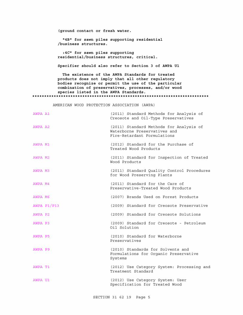
(ground contact or fresh water.
"4B" for sawn piles supporting residential /business structures.
:4C" for sawn piles supporting residential/business structures, critical.
Specifier should also refer to Section 3 of AWPA U1
The existence of the AWPA Standards for treated products does not imply that all other regulatory bodies recognize or permit the use of the particular combination of preservatives, processes, and/or wood species listed in the AWPA Standards.
**************************************************************************
AMERICAN WOOD PROTECTION ASSOCIATION (AWPA)
AWPA A1 (2011) Standard Methods for Analysis of Creosote and Oil-Type Preservatives
AWPA A2 (2011) Standard Methods for Analysis of Waterborne Preservatives and Fire-Retardant Formulations
AWPA M1 (2012) Standard for the Purchase of Treated Wood Products
AWPA M2 (2011) Standard for Inspection of Treated Wood Products
AWPA M3 (2011) Standard Quality Control Procedures for Wood Preserving Plants
AWPA M4 (2011) Standard for the Care of Preservative-Treated Wood Products
AWPA M6 (2007) Brands Used on Forest Products
AWPA P1/P13 (2009) Standard for Creosote Preservative
AWPA P2 (2009) Standard for Creosote Solutions
AWPA P3 (2009) Standard for Creosote - Petroleum Oil Solution
AWPA P5 (2010) Standard for Waterborne Preservatives
AWPA P9 (2010) Standards for Solvents and Formulations for Organic Preservative Systems
AWPA T1 (2012) Use Category System: Processing and Treatment Standard
AWPA U1 (2012) Use Category System: User Specification for Treated Wood
SECTION 31 62 19 Page 5

ASTM INTERNATIONAL (ASTM)
ASTM A1011/A1011M (2012) Standard Specification for Steel, Sheet, and Strip, Hot-Rolled, Carbon, Structural, High-Strength Low-Alloy and High-Strength Low-Alloy with Improved Formability and Ultra-High Strength
ASTM D1143/D1143M (2007; E 2009) Piles Under Static Axial Compressive Load
ASTM D25 (2012) Round Timber Piles
U.S. GENERAL SERVICES ADMINISTRATION (GSA)
FS RR-S-331 (Rev D) Shoes: For Wood Piles
1.2 SUBMITTALS
**************************************************************************NOTE: Review Submittal Description (SD) definitions in Section 01 33 00 SUBMITTAL PROCEDURES and edit the following list to reflect only the submittals required for the project.
The Guide Specification technical editors have designated those items that require Government approval, due to their complexity or criticality, with a "G". Generally, other submittal items can be reviewed by the Contractor's Quality Control System. Only add a “G” to an item, if the submittal is sufficiently important or complex in context of the project.
For submittals requiring Government approval on Army projects, a code of up to three characters within the submittal tags may be used following the "G" designation to indicate the approving authority. Codes for Army projects using the Resident Management System (RMS) are: "AE" for Architect-Engineer; "DO" for District Office (Engineering Division or other organization in the District Office); "AO" for Area Office; "RO" for Resident Office; and "PO" for Project Office. Codes following the "G" typically are not used for Navy, Air Force, and NASA projects.
Choose the first bracketed item for Navy, Air Force and NASA projects, or choose the second bracketed item for Army projects.
**************************************************************************
Government approval is required for submittals with a "G" designation; submittals not having a "G" designation are [for Contractor Quality Control approval.][for information only. When used, a designation following the "G" designation identifies the office that will review the submittal for the Government.] Submit the following in accordance with Section 01 33 00 SUBMITTAL PROCEDURES:
SECTION 31 62 19 Page 6

SD-02 Shop Drawings
Installation Drawings[; G][; G, [_____]]
SD-03 Product Data
Driving equipment[; G][; G, [_____]]
Cap or cushion block[; G][; G, [_____]]
Pile shoes[; G][; G, [_____]]
SD-04 Samples
Test piles[; G][; G, [_____]]
SD-06 Test Reports
Test piles[; G][; G, [_____]]
Load tests[; G][; G, [_____]]
Submit test pile results, and load test data and results as specified in PART 3.
SD-07 Certificates
Timber piles[; G][; G, [_____]]
Submit the inspection report of an independent inspection agency, approved by the Contracting Officer, stating that offered products comply with applicable AWPA Standards. Identify treatment on each piece by the quality mark of an agency accredited by the Board of Review of the America Lumber Standard Committee.
SD-11 Closeout Submittals
**************************************************************************NOTE: Delete these paragraphs if load testing is not required. Insert the number of test piles to be load tested or indicate on drawings. When it is desirable to show analysis for determination of allowable pile capacities from load tests and for relating load test capacities to allowable loads, include the following:
1. Test measurements: The ultimate test load (200 percent of allowable design load) must be maintained for a minimum 24 hours and then released. Cut broomed heads to sound wood before making settlement measurements. The safe or allowable design capacity of a test pile as determined from the results of load tests is the lesser of the two values computed according to the following:
(a) One-half the load that causes a net settlement after rebound of not more than 0.25 mm per metric ton
SECTION 31 62 19 Page 7

0.01 inch per ton of total test load.
(b) One-half the load that causes a maximum gross settlement of one inch provided that the load settlement curve shows no sign of failure.
2. Pile capacity: The capacity, as driven, of single piles not in clusters in the structure must be not less than [_____] metric tons tons. The capacity is determined by the following formulas, modified according to the data obtained by the load tests:
For single-acting hammers
[R = 2 WH/( s + 0.1P)85.678 W]
[R = 2 WH/(S + 0.1 P/W)]
For double-acting hammers
[R = 2.71E/( s + 0.1P)85.678 W]
[R = 2E/(S + 0.1 P/W]
Where R is the allowable static pile load in kg pounds, W is the weight of the striking part of the hammer in kg pounds, H is the effective height of fall in meters feet, E is the actual energy delivered by the hammer per blow in joule foot-pounds, S is the average net penetration in mm inches per blow for the last five blows after the pile has been driven to a depth where successive blows produce approximately equal net penetration (a minimum distance of one m 3 feet for friction piles), and P is the weight of the pile in [kg] [pounds]. If P is less than W, P/W is taken as unity.
Dynamic pile stresses must not exceed the crushing strength of piles.
**************************************************************************
Pile driving records[; G][; G, [_____]]
Submit complete and accurate pile driving records of installed piles to Contracting Officer within [15][_____] calendar days after completion of pile driving. Make pile driving records available to the Contracting Officer at the job site, within 24 hours after each day of pile driving. Provide pile records as specified in Part 3. Preparation of the record must be by, or under the direct supervision of a registered professional engineer.
1.3 QUALITY ASSURANCE
The producer must brand each treated pile, in accordance with AWPA M1, AWPA M2, AWPA M6, AWPA T1 and AWPA U1. Submit the inspection report of an independent inspection agency, approved by the Contracting Officer, stating
SECTION 31 62 19 Page 8

that offered products comply with applicable AWPA Standards, and that the plant conforms to AWPA M3.
1.4 PLANT INSPECTION
The Government, at its discretion, reserves the right to inspect the treating process. Notify the Contracting Officer at least 3 weeks prior to beginning the treatment, stating where preservative treatment will be done. Allow Government inspector access to all parts of the plant. Allow inspection of all facets of the treating process.
1.5 SUBSURFACE DATA AND INSTALLATION DRAWINGS
Subsurface soil data logs are shown [on the drawings] [in the specifications]. The subsurface [investigation reports] [and] [samples of materials as taken from subsurface investigations] are available for examination at [_____]. Drawings must indicate pile locations with GPS coordinates, location of proposed test piles, and be fully coordinated with the pile driving record as work progresses. Final Record Drawings must be submitted to the Contracting Officer [15][_____] calendar days prior to project closeout.
1.6 BASIS OF BID
**************************************************************************NOTE: Choose one of the following options.
**************************************************************************
**************************************************************************NOTE: Use this option if unit pricing IS NOT required. Where more than one length of pile is required, numbers of piles and their lengths shall be clearly designated on the drawings.
**************************************************************************
[Base bids on the number, circumference, and length of piles from tip to cutoff as indicated. Test piles must be [1.5 m] [5 feet] [_____] longer than bid length piles. From the data obtained as a result of driving the test piles [and conducting load tests], the Government will determine and list the calculated pile tip elevations [and the driving resistance] for all piles. The Government reserves the right to take up to 3 working days to review test pile driving records and take up to 3 additional working days to review and approve the contractor prepared schedule of pile lengths and locations. Use this list as the basis for ordering piles. Do not order production piles prior to receipt of the above information from the Government. Should the total number of piles or number of each length vary from that specified as the basis for bidding, the contract will be adjusted in accordance with "FAR 52.243-4, Changes." Adjustment in contract price will not be made for cutting off piles; for any portion of a pile remaining above the cutoff elevation; or for broken, damaged, or rejected piles.]
**************************************************************************NOTE: Use this option if unit pricing IS required. Specify unit price bid items for piling only where exact quantities cannot be practically determined prior to the actual work. For NAVFAC SE, use the reference to SF 1442; do not use references to Section 00 41 00 or document titled "Supplementary Instructions to Bidders" for NAVFAC SE. For NAVFAC
SECTION 31 62 19 Page 9

LANT, use option for the document titled "Supplementary Instructions to Bidders."
**************************************************************************
**************************************************************************NOTE: See paragraph entitled "Payment and Measurement" and related technical notes for requirements regarding quantity variations.
**************************************************************************
[Payment will be at contract unit price per unit length, including test piles, multiplied by the total length of acceptable piles actually installed. Test piles must be [1.5 m] [5 feet] [_____] longer than bid length piles. Base bids on the number of piles with pile length from tip to cutoff, as indicated, and on total linear footage of piling from tip to cutoff, including test piles, as specified in the [document titled "Supplementary Instructions to Bidders."] [Section 00 41 00 BID SCHEDULES.] [SF 1442, "Solicitation, Offer and Award" and "Schedule of Bid Items."] Include in bid a unit price per [load test and] unit length of piling based on the quantity stated in [document titled "Supplementary Instructions to Bidders."] [Section 00 41 00 BID SCHEDULES.] [SF 1442, "Solicitation, Offer and Award" and "Schedule of Bid Items."]
From the requirements, prepare a schedule of the number of piles of each length to be used and their location. Submit schedule for approval before any piles, except test piles, are ordered. The Government reserves the right to take up to 3 working days to review test pile driving records and take up to 3 additional working days to review and approve the contractor prepared schedule of pile lengths and locations. The excess pile length ordered over the tip to the cutoff length listed in the schedule as finally approved is the responsibility of the contractor. Use this list as the basis for ordering piles. Do not order production piles prior to receipt of the above information from the Government. [Adjustments in contract price will also be made for each increase or decrease in number of pile tests.]]
[1.6.1 Payment and Measurement
**************************************************************************NOTE: For unit pricing situations, enter the tip to cutoff pile length in the three blank spaces provided. Use tip to cutoff lengths 300 mm one footless than standard ordering lengths, to allow for a 300 mm one foot broomed test.
**************************************************************************
Requirements of "FAR 52.211-18, Variations in Estimated Quantity" do not apply to payment for piles. Each job pile and test pile acceptably provided from tip to cutoff will be paid for at the applicable contract unit price per unit length, which price includes all items incidental to furnishing and driving the piles including mobilization and demobilization; [jetting]; [spudding]; [pre-drilling]; [shoes and] collars where necessary; redriving uplifted piles; cutting off piles at the cutoff grade line; 300 mm one foot broomed and removed from each driven pile; treatment of the pile head exclusive of any capping; and additional 1.5 m 5 feet in furnished length for any test pile not driven beyond estimated pile length; and re-tapping of piles.
**************************************************************************
SECTION 31 62 19 Page 10

NOTE: Regarding the text and table below, for unit pricing situations, enter the tip to cutoff pile length in the three blank spaces provided. Use tip to cutoff lengths 300 mm one foot less than standard ordering lengths, to allow for a 300 mm one footbroomed end.
**************************************************************************
Payment for piles driven in lengths, as required, up to and including [_____] meters feet in place below the cutoff elevation, will be at the basic contract unit price bid. Payment for piles driven in lengths, as required, greater than [_____] meters feet below the cutoff elevation will be made at an adjusted unit price. Obtain the adjusted unit price by multiplying the basic contract unit price bid by the applicable factor shown in the table below.
**************************************************************************NOTE: Use the following adjustment factors to establish unit price factors for piles which are driven in lengths longer than the tip to cut-off lengths specified. Use a base factor of 1.00 for the tip to cutoff length specified for the project. or other lengths of piles, adjust the base factor by adding (or subtracting) the cumulative total of the adjustment factors listed below (i.e., to adjust the factor from a 10 m 34 foot pile with the butt circumference specified to a 13.5 m 44 foot pile with the butt circumference specified, subtract 0.08 from 1.00).
[Ordered Pile Length (meter)]
[Tip to Cut-Off Length (m)]
[Butt CircumferenceSpecified]
[Tip Circumference Specified]
[6] [5. 79] [ - ] [ - ]
[7.62] [7.31] [-0.04] [+0.05]
[9.14] [8.84] [-0.04] [+0.05]
[10.67] [10.36] [-0.04] [+0.05]
[12.19] [11.89] [-0.04] [+0.05]
[13.71] [13.41] [-0.04] [+0.05]
[15.24] [14.93] [-0.04] [+0.05]
[16.76] [16.46] [+0.10] [+0.05]
[18.29] [17.98] [+0.15] [+0.05]
[19.81] [19.51] [+0.15] [+0.10]
SECTION 31 62 19 Page 11

[Ordered Pile Length (meter)]
[Tip to Cut-Off Length (m)]
[Butt CircumferenceSpecified]
[Tip Circumference Specified]
[21.33] [21.03] [+0.15] [+0.15]
[22.86] [22.55] [+0.35] [+0.35]
[Ordered Pile Length (ft)]
[Tip to Cut-Off Length (ft)]
[Butt CircumferenceSpecified]
[Tip Circumference Specified]
[20] [19] [ - ] [ - ]
[25] [24] [-0.04] [+0.05]
[30] [29] [-0.04] [+0.05]
[35] [34] [-0.04] [+0.05]
[40] [39] [-0.04] [+0.05]
[45] [44] [-0.04] [+0.05]
[50] [49] [-0.04] [+0.05]
[55] [54] [+0.10] [+0.05]
[60] [59] [+0.15] [+0.05]
[65] [64] [+0.15] [+0.10]
[70] [69] [+0.15] [+0.15]
[75] [74] [+0.35] [+0.35]
**************************************************************************
Increase in Length Factor
[_____] meters 1.00
Over 0.0 to 1.5 meters, inclusive [_____]
Over 1.5 to 3.0 meters, inclusive [_____]
Over 3.0 to 4.5 meters, inclusive [_____]
Over 4.5 to 6.0 meters, inclusive [_____]
SECTION 31 62 19 Page 12

Increase in Length Factor
Over 6.0 to 7.5 meters, inclusive [_____]
Increase in Length Factor
[_____] feet 1.00
Over 0.0 to 5.0 feet, inclusive [_____]
ver 5.0 to 10.0 feet, inclusive [_____]
Over 10.0 to 15.0 feet, inclusive [_____]
Over 15.0 to 20.0 feet, inclusive [_____]
Over 20.0 to 25.0 feet, inclusive [_____]
When the Contracting Officer directs that a pile be cut off before the tip has reached the specified depth of tip penetration, payment will be made for that remaining length of pile not driven to the required minimum depth at the rate of 80 percent of the basic contract unit price bid, except when the Contractor is directed to order piles at a longer length which will be paid for at 80 percent of he adjusted unit price. No other payments for such cutoffs will be paid. Should the total tip to cutoff length of piles underrun that specified by more than 25 percent, the unit price per foot for such piles will be adjusted in accordance with "FAR 52.236-2, Differing Site Conditions." Any pile required to be pulled at no fault of the Contractor will be paid for at the applicable contract unit price for furnishing and driving the pile to the tip to cutoff length specified, plus 50 percent of that amount to cover the cost of pulling. Such pulled piles when redriven will be paid for at 50 percent of the applicable contract unit price for the length driven. [Payment for each complete test loading of a single pile will be made at the contract unit price per test, which price includes furnishing, placing, and removing testing equipment, and placing and removing test loads. At the direction of the Contracting Officer, load tests may be waived at a credit to the Government of the unit price bid therefore.] Authorized splices will be paid for at 30 times the unit price per unit length bod for piles. Off-site disposal for cutoffs is the Contractor's responsibility.]
PART 2 PRODUCTS
2.1 MATERIALS
2.1.1 Piles
**************************************************************************NOTE: Choose one of the following options.
**************************************************************************
**************************************************************************NOTE: The option below covers piles pressure treated with a preservative for land or fresh water. Specify or indicate on the drawings the minimum butt
SECTION 31 62 19 Page 13

or tip circumference of the pile. Use butt circumference for a friction pile and tip circumference for an end-bearing pile.
**************************************************************************
**************************************************************************NOTE: For NAVFAC LANT projects only, the following minimum circumferences normally apply:
Capacity (metric tons)
Minimum Butt Circumference for Friction Piles (Use Table 1. ASTM D25) (mm)
Minimum Tip Circumference for End-Bearing Piles (Use Table 2. ASTM D25) (mm)
(18) (965 mm) (483 mm)
(23) (965 or 1041 mm)* (559 mm)
(27) (1041 mm) (635 mm)
*Depends on specific soil conditions encountered at the site.
Capacity (tons)
Minimum Butt Circumference for Friction Piles (Use Table 1. ASTM D25) (inches)
Minimum Tip Circumference for End-Bearing Piles (Use Table 2. ASTM D25) (inches)
(200 (38 inches) (19 inches)
(25) (38 or 41 inches)* (22 inches)
(30) (41 inches) (25 inches)
*Depends on specific soil conditions encountered at the site.
**************************************************************************
[Provide pressure treated Douglas fir or southern pine clean-peeled piles conforming to ASTM D25. Minimum [butt circumference measured at 900 mm 3 feet from the butt] [tip circumference] must be [[_____] mm inches] [as indicated]. Piles must be in one piece. Splicing is [not ]permitted.]
**************************************************************************NOTE: The option below covers piles for use in construction where preservative treatment is not required. Specify or indicate on the drawings the minimum butt or tip circumference of the pile. Use butt circumference for friction piles and tip circumference for an end-bearing pile.
Numerous species of high density wood (Walaba, Purple Heart, etc.) are available for applications of untreated piles where environmental conditions prohibit the use of preservatives. Insert selected species in the blank provided below.
**************************************************************************
[Provide untreated [Douglas fir or southern pine ][_____][clean-peeled] [rough-peeled] [unpeeled] piles conforming to ASTM D25, AWPA T1, and AWPA U1.
SECTION 31 62 19 Page 14

Minimum [butt circumference measured at 900 mm 3 feet from the butt] [tip circumference] must be [[_____] mm inches] [as indicated]. Piles must be in one piece.[ Splices are not permitted.][ Splices are permitted.]]
2.1.2 Preservative Treatment
**************************************************************************NOTE: This paragraph covers preservative and preservative treatment for land or fresh water piling. Compliance with treatment standards must be confirmed, by an inspection report from an approved independent inspection agency, on each pile. Select appropriate treatment for intended use. Do not use CCA, ACA, or ACZA treatment for round timber piles when significant bending or impact loads are expected.
**************************************************************************
Provide [round]piles[ conforming to ASTM D25 and AWPA T1] treated with [creosote per AWPA A1, AWPA P1/P13, and AWPA P2], [or] [creosote-coal tar solution conforming to AWPA A1, AWPA P1/P13, and AWPA P3][waterborne preservative either, Ammoniacal Copper Arsenate (ACA), Ammoniacal Copper Zinc Arsenate (ACZA), or Chromated Copper Arsenate (CCA) in accordance with AWPA A2 and AWPA P5] for Land and Fresh Water Piles, confirmed by the report of an approved independent inspection agency.
[ Provide organically treated piles only, conforming to AWPA P9.]
2.1.3 Capblocks
Provide capblocks used between the cap and the hammer ram made of solid hardwood with grain parallel to the pile axis and enclosed in a close fitting housing of steel.[, or aluminum and approved industrial type plastic laminate disks stacked alternately in a steel housing.] Use steel plates at the top and bottom of the capblock.
If the capblock is other than that specified specified above, submit to the Contracting Officer at least two weeks prior to the commencement of test pile driving, detailed drawings and records of previous successful use.
Replacement of a wood capblock during the final driving of any pile is not allowed. The use of small wood blocks, wood chips, rope, or any other material permitting excessive loss of hammer energy is not permitted.
[2.1.4 Pile Shoes
FS RR-S-331. Boot type or point type specially fabricated for the purpose and the product of a manufacturer regularly engaged in the manufacture of pile fittings. Provide size to fit tip [specified] [indicated]. Fabricate boot-type of 5 mm 3/16 inch carbon steel conforming to ASTM A1011/A1011M, fully welded, with minimum three straps, each with 5 mm 3/16 inch nail hole. Fabricate point type of four 5 mm 3/16 inch steel plates, fully welded and sized to adequately cover full pointed area of pile; provide each plate with 5 or 6 mm 3/16 or 1/4 inch nail hole.
SECTION 31 62 19 Page 15

]PART 3 EXECUTION
3.1 EXAMINATION
Examine piles when delivered and when in the leads immediately before driving.
3.2 PREPARATION
Where the protective shell of treated wood is impaired at a point which after installation will be not less than 3 m 10 feet below the ground, make repairs in accordance with AWPA M4 unless the pile is damaged to such extent that it is rejected.
3.3 INSTALLATION
Cut piles at cut-off grade with pneumatic tools, sawing, or other approved method. Size bolt holes to ensure a driving fit.
3.3.1 Test Piles
Provide test piles of the same diameter and type and driven in the same manner as specified for production piles. Keep a record for each test pile and every unusual occurrence during pile driving. Record every increase or decrease of driving resistance and bring it to the attention of the Contracting Officer. Properly located test piles may be used in the finished work. Drive test piles in locations indicated.
[3.3.1.1 Load Tests
**************************************************************************NOTE: Delete these paragraphs if load testing is not required. Insert the number of test piles to be load tested or indicate on drawings. When it is desirable to show analysis for determination of allowable pile capacities from load tests and for relating load test capacities to allowable loads, include the following:
1. Test measurements: Maintain the ultimate test load (200 percent of allowable design load) for a minimum 24 hours and then release. Cut broomed heads to sound wood before making settlement measurements. The safe or allowable design capacity of a test pile as determined from the results of load tests must be the lesser of the two values computed according to the following:
(a) One-half the load that causes a net settlement after rebound of not more than 0.25 mm per metric ton 0.01 inch per ton of total test load.
(b) One-half the load that causes a maximum gross settlement of one inch provided that the load settlement curve shows no sign of failure.
2. Pile capacity: The capacity, as driven, of single piles not in clusters in the structure must be not less than [_____] [metric tons] [tons].
SECTION 31 62 19 Page 16

Determine the capacity by the following formulas, modified according to the data obtained by the load tests:
For single-acting hammers
[R = 2 WH/( s + 0.1P)85.678 W]
[R = 2 WH/(S + 0.1 P/W)]
For double-acting hammers
[R = 2.71E/( s + 0.1P)85.678 W]
[R = 2E/(S + 0.1 P/W]
Where: R is the allowable static pile load in kg pounds, W is the weight of the striking part of the hammer in kg pounds, H is the effective height of fall in meters feet, E is the actual energy delivered by the hammer per blow in joule foot-pounds, S is the average net penetration in mm inches per blow for the last five blows after the pile has been driven to a depth where successive blows produce approximately equal net penetration (a minimum distance of one m 3 feet for friction piles), and P is the weight of the pile in kg pounds. If P is less than W, P/W is taken as unity.
Dynamic pile stresses should not exceed the crushing strength of piles.
**************************************************************************
Perform load tests on [_____] test piles [as indicated] in accordance with ASTM D1143/D1143M, as modified herein. Use the method for either load supported directly by the pile or load from weighted box or platform or reaction frame attached to sufficient uplift piles to take safely the required load applied to the pile by hydraulic jack. Make load tests at locations directed by Contracting Officer. Additional load tests may be required by the Contracting Officer. If additional load tests are required, the contract will be adjusted in accordance with the clause entitled "Changes" of the Contract Clauses. Loading, testing, and recording and analysis of data must be under the direct supervision of a Registered Professional Engineer.
]3.3.2 Driving Piles
Drive without interruption to the ["calculated"] [indicated] tip elevation [to reach a driving resistance in accordance with the schedule that the Government will prepare from the test pile driving data]. If a pile fails to reach the ["calculated"] [indicated] pile tip elevation [or if the required driving resistance is reached before the ["calculated"] [indicated] pile tip elevation], notify the Contracting Officer who will determine the procedure to be followed. Drive production piles with the same hammer, cap block, and cushion materials and use the same operating conditions as test piles. Safe design capacity for each pile is [_____] metric tons tons.
SECTION 31 62 19 Page 17

3.3.3 Driving Equipment
Select and use a pile hammer of sufficient weight and energy to suitably install the specified pile without damage into the soils [as indicated] [expected to be encountered.] Place driving helmet or a cap and cushion block combination capable of protecting the head of the pile between the top of the pile and the ram to prevent impact damage to the pile. If block is damaged, split, highly compressed, charred or burned or has become spongy or deteriorated in any manner, replace with a new block. The helmet or block must uniformly transmit energy to the pile and minimum loss of energy.
3.4 JETTING OF PILES
**************************************************************************NOTE: Jetting should generally not be permitted for:
1. Piles dependent on side friction in fine-grained, low-permeability soils (high clay or silt content) where considerable time is required for the soil to reconsolidate around the piles
2. Piles subject to uplift
3. Piles adjacent to existing structures
4. Piles in closely spaced clusters unless the load capacity is confirmed by test and unless all jetting is done before final driving of any pile in the cluster.
**************************************************************************
Jetting [may be used] [will not be permitted]. [Discontinue jetting when the pile tip is approximately [1.5] [_____] meters [5] [_____] feet above the ["calculated"] [indicated] pile tip elevation. Drive the pile the final [1.5] [_____] meters [5] [_____] feet of penetration.]
3.5 PRE-AUGERING OR SPUDDING OF PILES
**************************************************************************NOTE: Pre-augering or spudding should generally not be permitted for piles dependent on side friction in fine-grained, low-permeability soils (high clay or silt content) where considerable time is required for the soil to reconsolidate around the piles.
**************************************************************************
Pre-augering or spudding of piles [may be used] [will be required] [will not be permitted]. [Discontinue pre-augering or spudding approximately [_____] meters feet above the[ "calculated"][ indicated] pile tip elevation. Drive the pile the final [_____] meters feet of penetration.]
3.6 TREATMENT
Treat cut, bored, dappled, and damaged surfaces as specified in AWPA M4.
SECTION 31 62 19 Page 18

3.7 TOLERANCES IN DRIVING
A variation of not more than 6 mm per 300 mm 0.25 inch per foot of pile length from the vertical for plumb piles or more than 13 mm per 300 mm 0.50 inch per foot of pile length from the required angle for batter piles is permitted. The center of butts must be within 100 mm 4 inches of the location indicated. Manipulation of piles is not permitted. In addition to complying with the stated tolerances, the clear distance between the heads of piles and the edges of pile caps must be a minimum of 125 mm 5 inches. With prior approval of the Contracting Officer, provide additional reinforcement and concrete to maintain the required minimum clear distance. Any redesign of pile caps or additional work required due to improper location of piles is the responsibility of the Contractor and must be approved by the Contracting Officer. Re-drive heaved piles to the required tip elevation. Remove and replace with new piles those damaged, mislocated, or driven out of alignment or provide additional piles, driven as directed.
[3.8 SPECIAL INSPECTION AND TESTING FOR SEISMIC-RESISTING SYSTEMS
**************************************************************************NOTE: Include this paragraph only when special inspection and testing for seismic-resisting systems is required by paragraph 3.2 of FEMA 302, NEHRP RECOMMENDED PROVISIONS FOR SEISMIC REGULATIONS FOR NEW BUILDINGS AND OTHER STRUCTURES.
This paragraph is applicable to both new buildings designed according to UFC 3-310-03A, "Seismic Design For Buildings", and to existing building seismic rehabilitation designs done according to UFC 3-301-05A, "Seismic Evaluation And Rehabilitation For Buildings".
The designer must indicate on the drawings all locations and all features for which special inspection and testing is required in accordance with Chapter 3 of FEMA 302. This includes indicating the locations of all structural components and connections requiring inspection.
Add any additional requirements as necessary.**************************************************************************
Perform special inspections and testing for seismic-resisting systems and components in accordance with Section 01 45 35 SPECIAL INSPECTIONS.
]3.9 PILE DRIVING RECORDS
Keep a complete and accurate record of each pile driven. Indicate the pile location, butt diameter, original length, ground elevation, tip elevation, cutoff elevation, penetration in blows per meter foot for the entire length of penetration for test piles, penetration in blows per meter foot for the last 3 m 10 feet for job piles, hammer data including make and size, and any unusual pile behavior or circumstances experienced during driving such as redriving, heaving, weaving, obstructions, jetting, spudding, and unanticipated interruptions which may occur. The following log is a preprinted form for recording pile driving data.
SECTION 31 62 19 Page 19

SECTION 31 62 19 Page 20

PILE DRIVING LOG
CONTRACT NO.________________________ CONTRACT NAME_______________________CONTRACTOR_____________________________ TYPE OF PILE_____________________PILE LOCATION_____________ PILE SIZE: BUTT/TIP: ________ LENGTH_________GROUND ELEVATION_________________________ CUT OFF ELEVATION______________PILE TIP ELEVATION_________________ VERTICAL (_____) BATTER 1 ON (_____)SPLICES ELEVATION____________________ COMPANY____________________________
HAMMER: MAKE & MODEL_________________ WT. RAM______________________ STROKE______________________ RAM RATED ENERGY__________________________ DESCRIPTION & DIMENSIONS OF DRIVING CAP_________________________________ CUSHION MATERIALS & THICKNESS___________________________________________
INSPECTOR_________________________________________________________________
"DEPTH" COLUMN OF PILE DRIVING RECORD REFERENCED TO: _____________________ CUT-OFF ELEVATION _____________________ FINISH FLOOR ELEVATION
TIME: START DRIVING_______ FINISH DRIVING________ DRIVING TIME_________ INTERRUPTIONS (TIME, TIP ELEV. & REASON)________________________________JET PRESSURE & ELEVATIONS_________________________________________________
__________________________________________________________________________
DRIVING RESISTANCE
__________________________________________________DEPTH NO. OF DEPTH NO. OF DEPTH NO. OF M BLOWS M BLOWS M BLOWS__________________________________________________ 0 _____ 5.4 _____ 10.8 _____ 0.3 _____ 5.7 _____ 11.1 _____ 0.6 _____ 6.0 _____ 11.4 _____ 0.9 _____ 6.3 _____ 11.7 _____ 1.2 _____ 6.6 _____ 12.0 _____ 1.5 _____ 6.9 _____ 12.3 _____ 1.8 _____ 7.2 _____ 12.6 _____ 2.1 _____ 7.5 _____ 12.9 _____ 2.4 _____ 7.8 _____ 13.2 _____ 2.7 _____ 8.1 _____ 13.5 _____ 3.0 _____ 8.4 _____ 13.8 _____ 3.3 _____ 8.7 _____ 14.1 _____ 3.6 _____ 9.0 _____ 14.4 _____ 3.9 _____ 9.3 _____ 14.7 _____ 4.2 _____ 9.6 _____ 15.0 _____ 4.5 _____ 9.9 _____ 15.3 _____ 4.8 _____ 10.2 _____ 15.6 _____ 5.1 _____ 10.5 _____ 15.9 _____
SHEET 1 OF 2
SECTION 31 62 19 Page 21

PILE DRIVING LOG 16.2 _____ 23.1 _____ 29.7 _____ 16.5 _____ 23.4 _____ 30.0 _____ 16.8 _____ 23.7 _____ 30.3 _____ 17.1 _____ 24.0 _____ 30.6 _____ 17.4 _____ 24.3 _____ 30.9 _____ 17.7 _____ 24.6 _____ 31.2 _____ 18.0 _____ 24.9 _____ 31.5 _____ 18.3 _____ 25.2 _____ 31.8 _____ 18.6 _____ 25.5 _____ 32.1 _____ 18.9 _____ 25.8 _____ 32.4 _____ 19.2 _____ 26.1 _____ 32.7 _____ 19.5 _____ 26.4 _____ 33.0 _____ 19.8 _____ 26.7 _____ 33.3 _____ 20.1 _____ 27.0 _____ 33.6 _____ 20.4 _____ 27.3 _____ 33.9 _____ 20.7 _____ 27.6 _____ 34.2 _____ 21.0 _____ 27.9 _____ 34.5 _____ 21.3 _____ 28.2 _____ 34.8 _____ 21.6 _____ 28.5 _____ 35.1 _____ 21.9 _____ 28.8 _____ 35.4 _____ 22.2 _____ 29.1 _____ 35.7 _____ 22.5 _____ 29.4 _____ 36.0 _____ 22.8 _____
__________________________________________________________________________
Driving resistance in blows per 25 mm for last 0.30 m of penetration:
DEPTH________ DEPTH________
25mm___ 50mm___100mm___125mm___150mm___175mm___200mm___225mm___ 250mm___
275mm___300mm___
ELEV._______ ELEV.________
REMARKS___________________________________________________________________
__________________________________________________________________________
CUT OFF ELEVATION: FROM DRAWING ________________
TIP ELEVATION = GROUND ELEVATION - DRIVEN DEPTH = ________________
DRIVEN LENGTH = CUT OFF ELEVATION - TIP ELEVATION = ________________
CUT OFF LENGTH = PILE LENGTH - DRIVEN LENGTH = ________________
SHEET 2 OF 2
SECTION 31 62 19 Page 22

PILE DRIVING LOG
CONTRACT NO.________________________ CONTRACT NAME_______________________CONTRACTOR_____________________________ TYPE OF PILE_____________________PILE LOCATION_____________ PILE SIZE: BUTT/TIP: ________ LENGTH_________GROUND ELEVATION_________________________ CUT OFF ELEVATION______________PILE TIP ELEVATION_________________ VERTICAL (_____) BATTER 1 ON (_____)SPLICES ELEVATION____________________ COMPANY____________________________
HAMMER: MAKE & MODEL_________________ WT. RAM______________________STROKE______________________ RAM RATED ENERGY____________________________DESCRIPTION & DIMENSIONS OF DRIVING CAP___________________________________CUSHION MATERIALS & THICKNESS_____________________________________________
INSPECTOR_________________________________________________________________
"DEPTH" COLUMN OF PILE DRIVING RECORD REFERENCED TO:_____________________ CUT-OFF ELEVATION_____________________ FINISH FLOOR ELEVATION
TIME: START DRIVING_______ FINISH DRIVING________ DRIVING TIME_________INTERRUPTIONS (TIME, TIP ELEV. & REASON)__________________________________JET PRESSURE & ELEVATIONS_________________________________________________
__________________________________________________________________________
DRIVING RESISTANCE
__________________________________________________DEPTH NO. OF DEPTH NO. OF DEPTH NO. OF FT. BLOWS FT. BLOWS FT. BLOWS__________________________________________________ 0 _____ 18 _____ 36 _____ 1 _____ 19 _____ 37 _____ 2 _____ 20 _____ 38 _____ 3 _____ 21 _____ 39 _____ 4 _____ 22 _____ 40 _____ 5 _____ 23 _____ 41 _____ 6 _____ 24 _____ 42 _____ 7 _____ 25 _____ 43 _____ 8 _____ 26 _____ 44 _____ 9 _____ 27 _____ 45 _____ 10 _____ 28 _____ 46 _____ 11 _____ 29 _____ 47 _____ 12 _____ 30 _____ 48 _____ 13 _____ 31 _____ 49 _____ 14 _____ 32 _____ 50 _____ 15 _____ 33 _____ 51 _____ 16 _____ 34 _____ 52 _____ 17 _____ 35 _____ 53 _____
SHEET 1 OF 2
SECTION 31 62 19 Page 23

PILE DRIVING LOG54 _____ 77 _____ 99 _____55 _____ 78 _____ 100 _____56 _____ 79 _____ 101 _____57 _____ 80 _____ 102 _____58 _____ 81 _____ 103 _____59 _____ 82 _____ 104 _____60 _____ 83 _____ 105 _____61 _____ 84 _____ 106 _____62 _____ 85 _____ 107 _____63 _____ 86 _____ 108 _____64 _____ 87 _____ 109 _____65 _____ 88 _____ 110 _____66 _____ 89 _____ 111 _____67 _____ 90 _____ 112 _____68 _____ 91 _____ 113 _____69 _____ 92 _____ 114 _____70 _____ 93 _____ 115 _____71 _____ 94 _____ 116 _____72 _____ 95 _____ 117 _____73 _____ 96 _____ 118 _____74 _____ 97 _____ 119 _____75 _____ 98 _____ 120 _____76 _____
__________________________________________________________________________
DRIVING RESISTANCE IN BLOWS PER INCH FOR LAST FOOT OF PENETRATION:
DEPTH________ DEPTH________
1"___2"___3"___4"___5"___6"___7"___8"___9"___10"___11"___12"___
ELEV._______ ELEV.________
REMARKS___________________________________________________________________
__________________________________________________________________________
CUT OFF ELEVATION: FROM DRAWING ________________
TIP ELEVATION = GROUND ELEVATION - DRIVEN DEPTH = ________________
DRIVEN LENGTH = CUT OFF ELEVATION - TIP ELEVATION = ________________
CUT OFF LENGTH = PILE LENGTH - DRIVEN LENGTH = ________________
SHEET 2 OF 2
-- End of Section --
SECTION 31 62 19 Page 24