UFGS 22 15 19.13 20 Large Nonlubricated Reciprocating Air ... 22 15 19.13 20.pdf · LARGE...
29
************************************************************************** USACE / NAVFAC / AFCEC / NASA UFGS-22 15 19.13 20 (November 2009) ----------------------------------- Preparing Activity: NAVFAC Superseding UFGS-22 15 19.13 20 (April 2006) UNIFIED FACILITIES GUIDE SPECIFICATIONS References are in agreement with UMRL dated April 2018 ************************************************************************** SECTION TABLE OF CONTENTS DIVISION 22 - PLUMBING SECTION 22 15 19.13 20 LARGE NONLUBRICATED RECIPROCATING AIR COMPRESSORS (OVER 300 HP) 11/09 PART 1 GENERAL 1.1 REFERENCES 1.2 GENERAL REQUIREMENTS 1.3 SUBMITTALS 1.4 QUALITY ASSURANCE 1.4.1 Intake and Discharge Pipe Calculations 1.4.2 Work Plan 1.4.3 Factory Testing Certification 1.4.4 Qualifications of Field Supervisors 1.4.5 Training Material 1.4.6 System Installation 1.4.7 Air Compressor System 1.5 SAFETY 1.6 EQUIPMENT ARRANGEMENT 1.7 ELECTRICAL REQUIREMENTS 1.8 SUPERVISION 1.9 DEFINITIONS 1.10 INSULATION 1.11 POSTED OPERATING INSTRUCTIONS PART 2 PRODUCTS 2.1 MATERIALS AND EQUIPMENT 2.2 AIR COMPRESSOR 2.2.1 Manufacturer's Certifications 2.2.2 Guaranteed Performance 2.2.3 Additional Performance Requirements 2.2.3.1 Air Quality 2.2.3.2 Ambient and Inlet Conditions Operating Ranges 2.2.3.3 Critical Speeds 2.2.4 Electrical Service Conditions 2.2.4.1 Air Compressor Drive Motor 2.2.4.2 Accessory electrical Service 2.2.5 Compressor Controls 2.2.5.1 Compressor Start-Up SECTION 22 15 19.13 20 Page 1
Transcript of UFGS 22 15 19.13 20 Large Nonlubricated Reciprocating Air ... 22 15 19.13 20.pdf · LARGE...

**************************************************************************USACE / NAVFAC / AFCEC / NASA UFGS- 22 15 19. 13 20 ( November 2009) - - - - - - - - - - - - - - - - - - - - - - - - - - - - - - - - - - -Pr epar i ng Act i v i t y: NAVFAC Super sedi ng UFGS- 22 15 19. 13 20 ( Apr i l 2006)
UNI FI ED FACI LI TI ES GUI DE SPECI FI CATI ONS
Ref er ences ar e i n agr eement wi t h UMRL dat ed Apr i l 2018**************************************************************************
SECTI ON TABLE OF CONTENTS
DI VI SI ON 22 - PLUMBI NG
SECTI ON 22 15 19. 13 20
LARGE NONLUBRI CATED RECI PROCATI NG AI R COMPRESSORS ( OVER 300 HP)
11/09
PART 1 GENERAL
1. 1 REFERENCES 1. 2 GENERAL REQUI REMENTS 1. 3 SUBMI TTALS 1. 4 QUALI TY ASSURANCE 1. 4. 1 I nt ake and Di schar ge Pi pe Cal cul at i ons 1. 4. 2 Wor k Pl an 1. 4. 3 Fact or y Test i ng Cer t i f i cat i on 1. 4. 4 Qual i f i cat i ons of Fi el d Super vi sor s 1. 4. 5 Tr ai ni ng Mat er i al 1. 4. 6 Syst em I nst al l at i on 1. 4. 7 Ai r Compr essor Syst em 1. 5 SAFETY 1. 6 EQUI PMENT ARRANGEMENT 1. 7 ELECTRI CAL REQUI REMENTS 1. 8 SUPERVI SI ON 1. 9 DEFI NI TI ONS 1. 10 I NSULATI ON 1. 11 POSTED OPERATI NG I NSTRUCTI ONS
PART 2 PRODUCTS
2. 1 MATERI ALS AND EQUI PMENT 2. 2 AI R COMPRESSOR 2. 2. 1 Manuf act ur er ' s Cer t i f i cat i ons 2. 2. 2 Guar ant eed Per f or mance 2. 2. 3 Addi t i onal Per f or mance Requi r ement s 2. 2. 3. 1 Ai r Qual i t y 2. 2. 3. 2 Ambi ent and I nl et Condi t i ons Oper at i ng Ranges 2. 2. 3. 3 Cr i t i cal Speeds 2. 2. 4 El ect r i cal Ser vi ce Condi t i ons 2. 2. 4. 1 Ai r Compr essor Dr i ve Mot or 2. 2. 4. 2 Accessor y el ect r i cal Ser vi ce 2. 2. 5 Compr essor Cont r ol s 2. 2. 5. 1 Compr essor St ar t - Up
SECTI ON 22 15 19. 13 20 Page 1

2. 2. 5. 2 Load Regul at i on 2. 2. 5. 3 Moni t or and Saf et y Cont r ol s 2. 2. 5. 4 Moni t or i ng I nst r ument s 2. 2. 6 Compr essor Desi gn Feat ur es 2. 2. 6. 1 Fr ame 2. 2. 6. 2 Cr ankshaf t and Mai n Bear i ngs 2. 2. 6. 3 Connect i ng Rod 2. 2. 6. 4 Cr ossheads 2. 2. 6. 5 Di st ance Pi eces 2. 2. 6. 6 Pi st ons and Pi st on Rods 2. 2. 6. 7 Pi st on Rod Packi ng 2. 2. 6. 8 Cyl i nder and cyl i nder Heads 2. 2. 6. 9 Val ves 2. 2. 6. 10 Compr essor Connect i ons 2. 2. 6. 11 I nt er cool er s, Af t er cool er , and Oi l Cool er s 2. 2. 6. 12 Lubr i cat i on Syst em 2. 2. 6. 13 Pul sat i on Cont r ol 2. 2. 7 El ect r i c Mot or s 2. 2. 7. 1 Mai n El ect r i c Dr i ve Mot or 2. 2. 7. 2 Accessor y and Rel at ed Equi pment Mot or s 2. 2. 8 Cont r ol Panel 2. 2. 9 Accessor i es 2. 2. 9. 1 Compr essor Ai r I nl et 2. 2. 9. 2 Compr essor Ai r Out l et 2. 2. 10 I nl et Ai r Fi l t er s 2. 2. 10. 1 Fi r st - St age Fi l t er 2. 2. 10. 2 Second- St age Fi l t er 2. 2. 10. 3 Thi r d- St age Fi l t er 2. 2. 10. 4 Fi l t er Medi a 2. 2. 11 I nl et Li ne Si l encer 2. 2. 12 Sound At t enuat i ng Encl osur e 2. 2. 12. 1 Encl osur e Fr ame 2. 2. 12. 2 Panel s 2. 2. 12. 3 Vent i l at i on 2. 3 AI R FLOW RATE AND PRESSURE RECORDER MEASUREMENT 2. 4 CARBON MONOXI DE MONI TOR 2. 4. 1 Sampl i ng Syst em 2. 4. 2 Test Syst em 2. 5 SOURCE QUALI TY CONTROL 2. 5. 1 Fact or y Test Pr ocedur es 2. 5. 2 Super vi s i on of Test i ng 2. 5. 3 Syst em Test 2. 5. 4 Appr oval of Test i ng Pr ocedur e 2. 5. 5 Cer t i f i cat i on of Per f or mance Test s
PART 3 EXECUTI ON
3. 1 I NSTALLATI ON 3. 2 GENERAL REQUI REMENTS FOR I NSTALLI NG AI R COMPRESSORS 3. 2. 1 Pr ompt I nst al l at i on 3. 2. 2 St ar t - Up Ser vi ces 3. 3 FI ELD QUALI TY CONTROL 3. 3. 1 Fi el d Test Pr ocedur es 3. 3. 1. 1 Per f or mance Test s 3. 3. 1. 2 I nst r ument at i on Test 3. 3. 1. 3 Sound Level Test s 3. 3. 1. 4 Oper at i onal Def i c i enci es 3. 3. 1. 5 Fi el d Test Tol er ances 3. 3. 2 Appr oval of Test i ng Pr ocedur e
SECTI ON 22 15 19. 13 20 Page 2

3. 4 TRAI NI NG OF GOVERNMENT PERSONNEL
- - End of Sect i on Tabl e of Cont ent s - -
SECTI ON 22 15 19. 13 20 Page 3

**************************************************************************USACE / NAVFAC / AFCEC / NASA UFGS- 22 15 19. 13 20 ( November 2009) - - - - - - - - - - - - - - - - - - - - - - - - - - - - - - - - - - -Pr epar i ng Act i v i t y: NAVFAC Super sedi ng UFGS- 22 15 19. 13 20 ( Apr i l 2006)
UNI FI ED FACI LI TI ES GUI DE SPECI FI CATI ONS
Ref er ences ar e i n agr eement wi t h UMRL dat ed Apr i l 2018**************************************************************************
SECTI ON 22 15 19. 13 20
LARGE NONLUBRI CATED RECI PROCATI NG AI R COMPRESSORS ( OVER 300 HP)11/09
**************************************************************************NOTE: Thi s gui de speci f i cat i on cover s t he r equi r ement s f or l ar ge nonl ubr i cat ed r eci pr ocat i ng ai r compr essor s l ar ger t han 224 kW 300 hp.
Adher e t o UFC 1- 300- 02 Uni f i ed Faci l i t i es Gui de Speci f i cat i ons ( UFGS) For mat St andar d when edi t i ng t hi s gui de speci f i cat i on or pr epar i ng new pr oj ect speci f i cat i on sect i ons. Edi t t hi s gui de speci f i cat i on f or pr oj ect speci f i c r equi r ement s by addi ng, del et i ng, or r evi s i ng t ext . For br acket ed i t ems, choose appl i cabl e i t em( s) or i nser t appr opr i at e i nf or mat i on.
Remove i nf or mat i on and r equi r ement s not r equi r ed i n r espect i ve pr oj ect , whet her or not br acket s ar e present.
Comment s, suggest i ons and r ecommended changes f or t hi s gui de speci f i cat i on ar e wel come and shoul d be submi t t ed as a Cr i t er i a Change Request ( CCR) .
**************************************************************************
**************************************************************************NOTE: Cool i ng t ower s or c l osed- c i r cui t cool er s, cool i ng wat er pi pi ng, and ot her i t ems ar e not i ncl uded and must be i ncl uded i n ot her sect i ons of t he pr oj ect speci f i cat i on.
**************************************************************************
**************************************************************************NOTE: The f ol l owi ng i nf or mat i on shal l be shown on t he pr oj ect dr awi ngs:
1. Compr essor , accessor y equi pment , and pi pi ng ar r angement and det ai l s .
2. Equi pment f oundat i ons.
3. Equi pment schedul es. I f equi pment schedul es i ncl ude oper at i ng condi t i ons f or t he compr essor , del et e t he i nf or mat i on f r om t hi s sect i on.
SECTI ON 22 15 19. 13 20 Page 4

**************************************************************************
PART 1 GENERAL
1. 1 REFERENCES
**************************************************************************NOTE: Thi s par agr aph i s used t o l i s t t he publ i cat i ons c i t ed i n t he t ext of t he gui de speci f i cat i on. The publ i cat i ons ar e r ef er r ed t o i n t he t ext by basi c desi gnat i on onl y and l i s t ed i n t hi s par agr aph by or gani zat i on, desi gnat i on, dat e, and t i t l e. Use t he Ref er ence Wi zar d' s Check Ref er ence f eat ur e when you add a Ref er ence I dent i f i er ( RI D) out s i de of t he Sect i on' s Ref er ence Ar t i c l e t o aut omat i cal l y pl ace t he r ef er ence i n t he Ref er ence Ar t i c l e. Al so use t he Ref er ence Wi zar d' s Check Ref er ence f eat ur e t o updat e t he i ssue dat es. Ref er ences not used i n t he t ext wi l l aut omat i cal l y be del et ed f r om t hi s sect i on of t he pr oj ect speci f i cat i on when you choose t o r econci l e r ef er ences i n t he publ i sh pr i nt pr ocess.
**************************************************************************
The publ i cat i ons l i s t ed bel ow f or m a par t of t hi s speci f i cat i on t o t he ext ent r ef er enced. The publ i cat i ons ar e r ef er r ed t o wi t hi n t he t ext by t he basi c desi gnat i on onl y.
AMERI CAN PETROLEUM I NSTI TUTE ( API )
API St d 618 ( 2007; R 2016) Reci pr ocat i ng Compr essor s f or Pet r ol eum, Chemi cal , and Gas I ndust r y Services
ASME I NTERNATI ONAL ( ASME)
ASME B1. 20. 1 ( 2013) Pi pe Thr eads, Gener al Pur pose ( I nch)
ASME B16. 1 ( 2015) Gr ay I r on Pi pe Fl anges and Fl anged Fi t t i ngs Cl asses 25, 125, and 250
ASME B16. 5 ( 2017) Pi pe Fl anges and Fl anged Fi t t i ngs NPS 1/ 2 Thr ough NPS 24 Met r i c/ I nch St andar d
ASME B16. 9 ( 2012) St andar d f or Fact or y- Made Wr ought St eel But t wel di ng Fi t t i ngs
ASME B40. 100 ( 2013) Pr essur e Gauges and Gauge Attachments
ASME BPVC SEC VI I I D1 ( 2015) BPVC Sect i on VI I I - Rul es f or Const r uct i on of Pr essur e Vessel s Di v i s i on 1
ASME PTC 9 ( 1970; R 1997) Di spl acement Compr essor s, Vacuum Pumps and Bl ower s ( f or hi st or i cal r ef er ence onl y)
SECTI ON 22 15 19. 13 20 Page 5

ASTM I NTERNATI ONAL ( ASTM)
ASTM A123/ A123M ( 2017) St andar d Speci f i cat i on f or Zi nc ( Hot - Di p Gal vani zed) Coat i ngs on I r on and St eel Pr oduct s
ASTM A153/ A153M ( 2016) St andar d Speci f i cat i on f or Zi nc Coat i ng ( Hot - Di p) on I r on and St eel Hardware
ASTM A307 ( 2014; E 2017) St andar d Speci f i cat i on f or Car bon St eel Bol t s, St uds, and Thr eaded Rod 60 000 PSI Tensi l e St r engt h
ASTM A36/ A36M ( 2014) St andar d Speci f i cat i on f or Car bon St r uct ur al St eel
ASTM A53/ A53M ( 2012) St andar d Speci f i cat i on f or Pi pe, St eel , Bl ack and Hot - Di pped, Zi nc- Coat ed, Wel ded and Seaml ess
ASTM B111/ B111M ( 2011) St andar d Speci f i cat i on f or Copper and Copper - Al l oy Seaml ess Condenser Tubes and Fer r ul e St ock
ASTM B171/ B171M ( 2012) St andar d Speci f i cat i on f or Copper - Al l oy Pl at e and Sheet f or Pr essur e Vessel s, Condenser s and Heat Exchanger s
ASTM B209 ( 2014) St andar d Speci f i cat i on f or Al umi num and Al umi num- Al l oy Sheet and Pl at e
ASTM B209M ( 2014) St andar d Speci f i cat i on f or Al umi num and Al umi num- Al l oy Sheet and Pl at e ( Met r i c)
ASTM C553 ( 2013) St andar d Speci f i cat i on f or Mi ner al Fi ber Bl anket Ther mal I nsul at i on f or Commer ci al and I ndust r i al Appl i cat i ons
ASTM E84 ( 2018) St andar d Test Met hod f or Sur f ace Bur ni ng Char act er i st i cs of Bui l di ng Materials
COMPRESSED GAS ASSOCI ATI ON ( CGA)
CGA G- 7. 1 ( 2011) Commodi t y Speci f i cat i on f or Ai r ; 5t h Edi t i on
I NSTI TUTE OF ELECTRI CAL AND ELECTRONI CS ENGI NEERS ( I EEE)
I EEE 112 ( 2017) St andar d Test Pr ocedur e f or Pol yphase I nduct i on Mot or s and Gener at or s
I NTERNATI ONAL ORGANI ZATI ON FOR STANDARDI ZATI ON ( I SO)
I SO 2151 ( 2004) Acoust i cs - Noi se Test Code f or Compr essor s and Vacuum Pumps - Engi neer i ng Met hod ( Gr ade 2)
SECTI ON 22 15 19. 13 20 Page 6
NATI ONAL ELECTRI CAL MANUFACTURERS ASSOCI ATI ON ( NEMA)
NEMA I CS 2 ( 2000; R 2005; Er r at a 2008) I ndust r i al Cont r ol and Syst ems Cont r ol l er s, Cont act or s, and Over l oad Rel ays Rat ed 600 V
NEMA I CS 6 ( 1993; R 2016) I ndust r i al Cont r ol and Syst ems: Encl osur es
NEMA MG 1 ( 2016; SUPP 2016) Mot or s and Gener at or s
U. S. DEPARTMENT OF DEFENSE ( DOD)
MIL-A-3316 ( 1987; Rev C; Am 2 1990) Adhesi ves, Fi r e- Resi st ant , Ther mal I nsul at i on
MIL-T-19646 ( 1990; Rev A) Ther momet er , Gas Act uat ed, Remot e Readi ng
U. S. NATI ONAL ARCHI VES AND RECORDS ADMI NI STRATI ON ( NARA)
29 CFR 1910. 219 Mechani cal Power Tr ansmi ssi on Appar at us
1. 2 GENERAL REQUI REMENTS
Sect i on 23 03 00. 00 20 BASI C MECHANI CAL MATERI ALS AND METHODS, appl i es t o t hi s sect i on except as speci f i ed her ei n.
1. 3 SUBMITTALS
**************************************************************************NOTE: Revi ew Submi t t al Descr i pt i on ( SD) def i ni t i ons i n Sect i on 01 33 00 SUBMI TTAL PROCEDURES and edi t t he f ol l owi ng l i s t t o r ef l ect onl y t he submi t t al s r equi r ed f or t he pr oj ect .
The Gui de Speci f i cat i on t echni cal edi t or s have desi gnat ed t hose i t ems t hat r equi r e Gover nment appr oval , due t o t hei r compl exi t y or cr i t i cal i t y , wi t h a " G" . Gener al l y, ot her submi t t al i t ems can be r evi ewed by t he Cont r act or ' s Qual i t y Cont r ol Syst em. Onl y add a “ G” t o an i t em, i f t he submi t t al i s suf f i c i ent l y i mpor t ant or compl ex i n cont ext of t he pr oj ect .
For submi t t al s r equi r i ng Gover nment appr oval on Ar my pr oj ect s, a code of up t o t hr ee char act er s wi t hi n t he submi t t al t ags may be used f ol l owi ng t he " G" desi gnat i on t o i ndi cat e t he appr ovi ng aut hor i t y. Codes f or Ar my pr oj ect s usi ng t he Resi dent Management Syst em ( RMS) ar e: " AE" f or Ar chi t ect - Engi neer ; " DO" f or Di st r i c t Of f i ce ( Engi neer i ng Di v i s i on or ot her or gani zat i on i n t he Di st r i c t Of f i ce) ; " AO" f or Ar ea Of f i ce; " RO" f or Resi dent Of f i ce; and " PO" f or Pr oj ect Of f i ce. Codes f ol l owi ng t he " G" t ypi cal l y ar e not used f or Navy, Ai r For ce, and NASA pr oj ect s.
SECTI ON 22 15 19. 13 20 Page 7

Use t he " S" c l assi f i cat i on onl y i n SD- 11 Cl oseout Submi t t al s. The " S" f ol l owi ng a submi t t al i t em i ndi cat es t hat t he submi t t al i s r equi r ed f or t he Sust ai nabi l i t y eNot ebook t o f ul f i l l f eder al l y mandat ed sust ai nabl e r equi r ement s i n accor dance wi t h Sect i on 01 33 29 SUSTAI NABI LI TY REPORTI NG.
Choose t he f i r st br acket ed i t em f or Navy, Ai r For ce and NASA pr oj ect s, or choose t he second br acket ed i t em f or Ar my pr oj ect s.
**************************************************************************
Gover nment appr oval i s r equi r ed f or submi t t al s wi t h a " G" desi gnat i on; submi t t al s not havi ng a " G" desi gnat i on ar e [ f or Cont r act or Qual i t y Cont r ol appr oval . ] [ f or i nf or mat i on onl y. When used, a desi gnat i on f ol l owi ng t he " G" desi gnat i on i dent i f i es t he of f i ce t hat wi l l r evi ew t he submi t t al f or t he Gover nment . ] Submi t t al s wi t h an " S" ar e f or i ncl usi on i n t he Sust ai nabi l i t y eNot ebook, i n conf or mance t o Sect i on 01 33 29 SUSTAI NABI LI TY REPORTI NG. Submi t t he f ol l owi ng i n accor dance wi t h Sect i on 01 33 00 SUBMI TTAL PROCEDURES:
SD- 02 Shop Dr awi ngs
Ai r compr essor syst em
I ncl ude wi r i ng di agr ams of t he ai r compr essor syst em wi t h al l accessor i es. The mi ni mum accept abl e scal e i s [ 1: 50 1/ 4 i nch t o one f oot ] [ _____] .
SD- 03 Pr oduct Dat a
**************************************************************************NOTE: I ncl ude car bon monoxi de moni t or i n syst ems whi ch ar e used f or br eat hi ng ai r per DM 3. 5, Sect i on 3.
**************************************************************************
Ai r compr essor
I nl et ai r f i l t er s
I nl et l i ne s i l encer
Ai r f l ow r at e and pr essur e r ecor der
[ Car bon monoxi de moni t or ]
Fi l t er housi ng
Submi t manuf act ur er ' s cat al og dat a f or compr essor and auxi l i ar y equi pment i n t he f or mat pr ovi ded i n API St d 618, Appendi x A. For ai r compr essor s, i ncl ude af t er cool er , i nt er cool er s, oi l cool er , l ubr i cat i on syst em, and cont r ol val ves. Submi t ai r compr essor i nt er cool er , and af t er cool er per f or mance cur ves at speci f i ed summer desi gn condi t i ons.
SD- 05 Desi gn Dat a
I nt ake and di schar ge pi pe cal cul at i ons
SECTI ON 22 15 19. 13 20 Page 8

SD- 06 Test Repor t s
Ai r compr essor per f or mance t est s
Sound l evel and r un- i n t est s
Obt ai n appr oval pr i or t o shi ppi ng compr essor .
Ai r compr essor per f or mance t est s
I nst r ument at i on t est
Sound l evel t est s
Ai r compr essor syst em t est
The t est super vi sor shal l cer t i f y per f or mance by t est t o be i n compl i ance wi t h speci f i cat i ons.
SD- 07 Cer t i f i cat es
Wor k pl an
Fact or y t est pr ocedur es
Fact or y t est i ng cer t i f i cat i on
Qual i f i cat i ons of f i el d super vi sor s
Fi el d t est pr ocedur es
Tr ai ni ng mat er i al
Ai r compr essor syst em
Ai r compr essor syst em i nst al l at i on
SD- 10 Oper at i on and Mai nt enance Dat a
**************************************************************************NOTE: Obt ai n appr oval of equi pment wi t h pr opr i et ar y mai nt enance r equi r ement s f r om t he appr opr i at e cont r act s of f i ce.
**************************************************************************
Ai r compr essor syst em, Dat a Package 3
Submi t i n accor dance wi t h Sect i on 01 78 23 OPERATI ON AND MAI NTENANCE DATA.
SD- 11 Cl oseout Submi t t al s
Post ed oper at i ng i nst r uct i ons f or ai r compr essor
Submi t t ext .
SECTI ON 22 15 19. 13 20 Page 9

1. 4 QUALI TY ASSURANCE
1. 4. 1 I nt ake and Di schar ge Pi pe Cal cul at i ons
Submi t i nt ake and di schar ge pi pe cal cul at i ons t o show i nt ake and di schar ge pi pi ng ar e not subj ect t o damagi ng r esonance pul sat i ons. I ncl ude ef f ect s of pul sat i on damper s and sur ge chamber s, i f r equi r ed t o l i mi t pul sat i on.
1. 4. 2 Wor k Pl an
Submi t a wr i t t en schedul e of dat es of i nst al l at i on, st ar t - up, checkout , and t est of equi pment .
1. 4. 3 Fact or y Test i ng Cer t i f i cat i on
Submi t a st at ement t hat t he ai r compr essor f act or y i s equi pped t o per f or m al l r equi r ed f act or y t est s. Submi t i n accor dance wi t h par agr aph ent i t l ed " Manuf act ur er ' s Cer t i f i cat i ons. "
1. 4. 4 Qual i f i cat i ons of Fi el d Super vi sor s
Submi t t he name and cer t i f i ed wr i t t en r esume of t he engi neer or t echni c i an, l i s t i ng educat i on, f act or y t r ai ni ng and i nst al l at i on, st ar t - up, and t est i ng super vi s i on exper i ence f or at l east t wo pr oj ect s i nvol v i ng compr essor s s i mi l ar t o t hose i n t hi s cont r act .
1. 4. 5 Tr ai ni ng Mat er i al
Submi t a det ai l ed t r ai ni ng pr ogr am syl l abus f or t r ai ni ng of gover nment per sonnel , i ncl udi ng i nst r uct i onal mat er i al s at l east t hr ee weeks pr i or t o st ar t of t est s.
1. 4. 6 Syst em I nst al l at i on
Submi t cer t i f i cat i on of ai r compr essor syst em per f or mance conf or mi ng t o ASME PTC 9. Submi t cer t i f i cat i on of pr oper syst em i nst al l at i on i n accor dance wi t h par agr aph ent i t l ed " Super vi s i on. "
1. 4. 7 Ai r Compr essor Syst em
Submi t oper at i on and mai nt enance dat a i n accor dance wi t h Sect i on 01 78 23 OPERATI ON AND MAI NTENANCE DATA. Ai r compr essor syst em dat a shal l cont ai n i nf or mat i on r equi r ed f or mai nt enance and r epai r and shal l cont ai n no evi dence t hat pr opr i et ar y mai nt enance ar r angement s wi t h t he manuf act ur er wi l l be necessar y. Compr essor s whi ch wi l l r equi r e pr opr i et ar y mai nt enance ar r angement wi t h t he manuf act ur er r equi r e Gover nment r evi ew and appr oval . The compr essor s may be di sappr oved i f c i r cumst ances do not j ust i f y appr oval of compr essor s wi t h l i mi t ed avai l abi l i t y of mai nt enance.
1. 5 SAFETY
Const r uct al l component s of t he uni t i n accor dance wi t h t he r equi r ement s of OSHA 29 CFR 1910. 219. Requi r ement s i ncl ude shaf t coupl i ng guar ds as speci f i ed i n Sect i on 23 03 00. 00 20 BASI C MECHANI CAL MATERI ALS AND METHODS, i nsul at i on and j acket i ng wi t h manuf act ur er st andar d cover i ng or al umi num sheet of al l sur f aces at 52 degr ees C 125 degr ees F and hi gher wi t hi n a hei ght of 2. 10 met er 7 f eet f r om f l oor l evel , and use of el ect r i cal saf et y devi ces. Ther mal i nsul at i on, f ur ni shed by equi pment manuf act ur er , shal l conf or m t o ASTM C553, Type I ( f l exi bl e r esi l i ent ) , Cl ass B- 5 ( up t o 204
SECTI ON 22 15 19. 13 20 Page 10

degr ees C 400 degr ees F) , 32 kg/ m3 2 pcf nomi nal . Cement i nsul at i on t o sur f ace wi t h MIL-A-3316 , Cl ass 2, adhesi ve and f ast en wi t h 16 gage wi r e bands at maxi mum 405 mm 16 i nches on cent er spaci ng. Cover i nsul at i on wi t h ASTM B209M ASTM B209 sheet al umi num j acket .
1. 6 EQUI PMENT ARRANGEMENT
Ar r angement sel ect ed shal l mai nt ai n 0. 90 met er s 3 f oot c l ear ance f or access passage and 1. 20 met er s 4 f oot c l ear ance f or per sonnel t o oper at e equi pment . Ther e ar e subst ant i al physi cal and connect i on poi nt di f f er ences among t he sever al ai r compr essor s whi ch compl y wi t h t hi s speci f i cat i on. The Cont r act or shal l be r esponsi bl e f or sel ect i ng equi pment and submi t t i ng ar r angement dr awi ngs cover i ng r equi r ed changes f or appr oval by t he Cont r act i ng Of f i cer . Changes f r om t he equi pment ar r angement shown on t he cont r act dr awi ngs shal l be per f or med by t he Cont r act or at no addi t i onal cost t o t he Gover nment .
1. 7 ELECTRI CAL REQUI REMENTS
Compl y wi t h t he r equi r ement s of Sect i on 26 20 00 I NTERI OR DI STRI BUTI ON SYSTEM, [ and [ _____] ] .
1. 8 SUPERVISION
The Cont r act or shal l obt ai n t he ser vi ces of a qual i f i ed engi neer or t echni c i an f r om t he compr essor manuf act ur er t o super vi se i nst al l at i on, st ar t - up, and t est i ng of t he compr essor . Af t er sat i sf act or y i nst al l at i on of t he equi pment , t he engi neer or t echni c i an shal l pr ovi de a s i gned cer t i f i cat i on t hat t he equi pment i s i nst al l ed i n accor dance wi t h t he manuf act ur er ' s r ecommendat i ons.
1. 9 DEFINITIONS
API St d 618 and t he f ol l owi ng:
Compr essor power i s shaf t power at shaf t coupl i ng, i ncl udi ng al l l osses and connect ed appur t enances.
1. 10 INSULATION
Ther mal and acoust i cal i nsul at i on shal l have f l ame spr ead r at i ng not hi gher t han 75, and smoke devel oped r at i ng not hi gher t han 150 when t est ed i n accor dance wi t h ASTM E84.
1. 11 POSTED OPERATI NG I NSTRUCTI ONS
Pr ovi de f or ai r compr essor . I ncl ude st ar t - up and shut down sequence instructions.
PART 2 PRODUCTS
2. 1 MATERI ALS AND EQUI PMENT
Mat er i al s and equi pment compl et e wi t h accessor i es shal l be sel ect ed by t he Cont r act or f or per f or mance compat i bi l i t y .
SECTI ON 22 15 19. 13 20 Page 11

2. 2 AI R COMPRESSOR
**************************************************************************NOTE: Pr ovi de sound at t enuat i ng encl osur e or make ot her pr ovi s i ons t o compl y wi t h OPNAV 5100. 23, Chapt er 18, par agr aph 18202, " Pr event i ve Measur es, " whi ch cont ai ns noi se abat ement r equi r ement s f or new machi ner y and equi pment . I f manuf act ur er s do not f ur ni sh sound at t enuat i ng encl osur e as a f act or y- bui l t opt i on, del et e t he sound encl osur e f r om t hi s sect i on and consi der ot her means f or meet i ng noi se abat ement r equi r ement s, such as: ( 1) ot her t ypes of compr essor s whi ch ar e f ur ni shed wi t h sound at t enuat i ng encl osur es, ( 2) f i el d er ect ed equi pment encl osur es f r om sour ces ot her t han t he compr essor manuf act ur er , and ( 3) soundpr oof ed of f i ce or per sonnel encl osur e.
**************************************************************************
The ai r compr essor s shal l be posi t i ve di spl acement , r eci pr ocat i ng, doubl e- act i ng compr essor s del i ver i ng oi l - f r ee ai r . No l ubr i cant shal l be used wi t hi n t he compr essi on cyl i nder s. I ncl ude ai r compr essor , el ect r i c mot or dr i ver , cool er s, l ubr i cat i on syst em, and r egul at i on and cont r ol syst ems mount ed on a common base f r ame, and, i f r equi r ed, compl et el y encl osed f or noi se cont r ol .
2. 2. 1 Manuf act ur er ' s Cer t i f i cat i ons
The manuf act ur er shal l cer t i f y t hat t he ai r compr essor s pr oposed ar e of t he same desi gn, const r uct i on, s i ze, and of equal or not mor e t han 10 per cent smal l er i n capaci t y as compr essor s whi ch have been i n sat i sf act or y cont i nuous ser vi ce f or at l east 2 year s at not l ess t han t wo l ocat i ons. Fur ni sh t he name of t he owner , t he addr ess of t he i nst al l at i on, and t he name of a per son at t he i nst al l at i on who can be cont act ed f or ver i f i cat i on. The manuf act ur er shal l al so cer t i f y t hat t he f act or y i s equi pped t o per f or m al l r equi r ed f act or y t est s.
2. 2. 2 Guar ant eed Per f or mance
**************************************************************************NOTE: Desi gner shoul d f ur ni sh r equi r ed i nf or mat i on t o compl et e t he speci f i cat i on.
**************************************************************************
a. Net compr essed ai r out put ( Al l packi ng and seal l osses shal l be consi der ed i nt er nal and not i ncl uded i n t he net out put ) ( pl us or mi nus 2 per cent ) : [ _____] st andar d l i t er per second ( L/ s) SCFM
b. Out put pr essur e i mmedi at el y downst r eam of af t er cool er ( mi nus zer o pl us 4 per cent ) : 862 kPa ( gage) 125 psi g
c. Out put ai r maxi mum t emper at ur e downst r eam of af t er cool er : 38 degr ees C 100 degr ees F
d. I nl et ai r pr essur e at f i r st s t age: [ _____] kPa ( absol ut e) psi g
e. I nl et ai r t emper at ur e at f i r s t st age: [ _____] degr ees C F
f . I nl et ai r f i l t r at i on ef f i c i ency: 99. 9 per cent of 0. 5 mi cr on s i ze
SECTI ON 22 15 19. 13 20 Page 12

g. Bar omet r i c pr essur e: [ _____] kPa ( absol ut e) psi g
h. Rel at i ve humi di t y: [ _____] per cent
i . Cool i ng wat er i nl et t emper at ur e: [ _____] degr ees C F
j . Tot al cool i ng wat er f l ow r at e: [ _____] L/ s gpm
k. Maxi mum cool i ng wat er pr essur e dr op t hr ough t he compr essor and any i nt er cool er , af t er cool er , or oi l cool er : [ _____] [ 55 kPa] [ 8 psi ]
l . Maxi mum compr essor power r equi r ed. ( Pl us or mi nus 4 per cent ) : [ _____] kW hp
m. Unl oaded compr essor hor sepower ( max. ) : [ _____] kW hp
**************************************************************************NOTE: Pr ovi de sound at t enuat i ng encl osur e or make ot her pr ovi s i ons t o compl y wi t h OPNAV 5100. 23, Chapt er 18, par agr aph 18202, " Pr event i ve Measur es, " whi ch cont ai ns noi se abat ement r equi r ement s f or new machi ner y and equi pment . I f manuf act ur er s do not f ur ni sh sound at t enuat i ng encl osur e as a f act or y- bui l t opt i on, del et e t he sound encl osur e f r om t hi s sect i on and consi der ot her means f or meet i ng noi se abat ement r equi r ement s, such as: ( 1) ot her t ypes of compr essor s whi ch ar e f ur ni shed wi t h sound at t enuat i ng encl osur es, ( 2) f i el d er ect ed equi pment encl osur es f r om sour ces ot her t han t he compr essor manuf act ur er , and ( 3) soundpr oof ed of f i ce or per sonnel encl osur e.
**************************************************************************
n. Maxi mum sound l evel s one met er hor i zont al f r om compr essor and 1. 5 met er s 5 f eet above f l oor as measur ed per I SO 2151: 84 dBA, 90 dB f or any oct ave band.
o. Maxi mum compr essor speed: 550 r pm
p. Maxi mum pi st on speed: 3 m/ s 590 f pm
q. Maxi mum power per 47 L/ s 100 ACFM: 16. 40 kW 22 hp.
2. 2. 3 Addi t i onal Per f or mance Requi r ement s
2. 2. 3. 1 Ai r Qual i t y
**************************************************************************NOTE: Compr essor s used t o pr ovi de br eat hi ng ai r shal l be s i t uat ed t o avoi d ent r y of cont ami nat ed ai r i nt o t he syst em and sui t abl e i n- l i ne f i l t er s i nst al l ed t o f ur t her assur e br eat hi ng ai r qual i t y . A r ecei ver of suf f i c i ent capaci t y t o enabl e t he r espi r at or wear er t o escape f r om a cont ami nat ed at mospher e i n t he event of compr essor f ai l ur e i s al so r equi r ed.
**************************************************************************
SECTI ON 22 15 19. 13 20 Page 13

Ai r at compr essor i nt ake wi l l be consi der ed br eat hi ng ai r qual i t y conf or mi ng t o CGA G- 7. 1, Type I , Gr ade D or bet t er . Ai r compr essor s shal l i nt r oduce no mat er i al , gases, or par t i c l es, or chemi cal l y al t er any mat er i al s t hat wi l l adver sel y af f ect or r educe t he qual i t y of t he ai r passi ng t hr ough t he uni t .
2. 2. 3. 2 Ambi ent and I nl et Condi t i ons Oper at i ng Ranges
**************************************************************************NOTE: Desi gner shoul d f ur ni sh r equi r ed i nf or mat i on t o compl et e t he speci f i cat i on.
**************************************************************************
Al l owi ng f or r at i onal engi neer i ng per f or mance adj ust ment s due t o var i at i ons i n ambi ent and i nl et condi t i ons, t he compr essor shal l be desi gned, equi pped, and f ur ni shed t o be f ul l y oper at i onal wi t hout abnor mal wear t hr oughout t he ent i r e r ange bet ween and i ncl udi ng t he l i mi t s of t he wi nt er and summer desi gn condi t i ons speci f i ed.
a. Summer desi gn condi t i ons:
I nl et ai r : [ _____] degr ees C F dr y bul b and [ _____] degr ees C F wet bul b t emper at ur es, [ _____] per cent r el at i ve humi di t y I nl et cool i ng wat er : [ _____] degr ees C F, Ambi ent compr essor r oom t emper at ur e: [ _____] degr ees C F, Bar omet r i c pr essur e: [ _____] kPa ( absol ut e) psi g
b. Wi nt er desi gn condi t i ons:
I nl et ai r : [ _____] degr ees C F dr y bul b and [ _____] degr ees C F wet bul b t emper at ur es, [ _____] per cent r el at i ve humi di t y I nl et cool i ng wat er : [ _____] degr ees C F, Ambi ent compr essor r oom t emper at ur e: [ _____] degr ees C F, Bar omet r i c pr essur e: [ _____] kPa ( absol ut e) psi g.
2. 2. 3. 3 Cr i t i cal Speeds
API St d 618, par agr aph 2. 5. 1.
2. 2. 4 El ect r i cal Ser vi ce Condi t i ons
2. 2. 4. 1 Ai r Compr essor Dr i ve Mot or
[ _____] Vol t s, 3 phase, 3 wi r e, 60 her t z el ect r i cal ser vi ce.
2. 2. 4. 2 Accessor y el ect r i cal Ser vi ce
**************************************************************************NOTE: Change accessor y vol t ages i f r equi r ed f or s i t e condi t i ons.
**************************************************************************
See Tabl e I .
SECTI ON 22 15 19. 13 20 Page 14
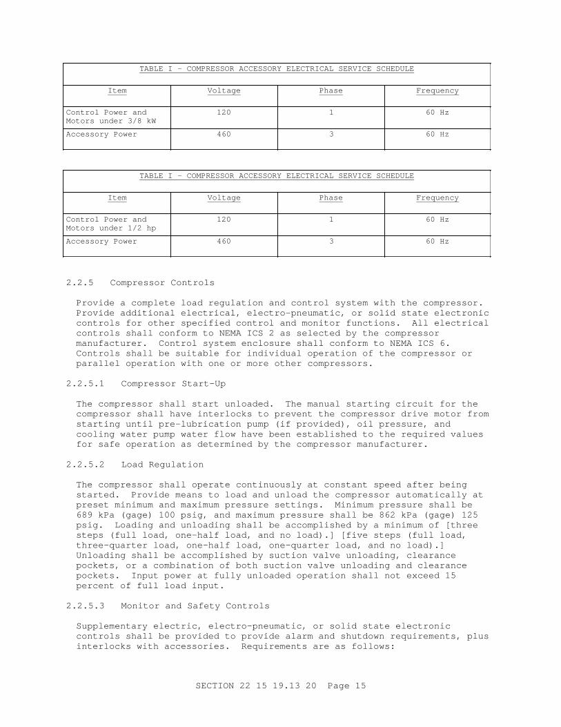
TABLE I - COMPRESSOR ACCESSORY ELECTRI CAL SERVI CE SCHEDULE
Item Voltage Phase Frequency
Cont r ol Power and Mot or s under 3/ 8 kW
120 1 60 Hz
Accessor y Power 460 3 60 Hz
TABLE I - COMPRESSOR ACCESSORY ELECTRI CAL SERVI CE SCHEDULE
Item Voltage Phase Frequency
Cont r ol Power and Mot or s under 1/ 2 hp
120 1 60 Hz
Accessor y Power 460 3 60 Hz
2. 2. 5 Compr essor Cont r ol s
Pr ovi de a compl et e l oad r egul at i on and cont r ol syst em wi t h t he compr essor . Pr ovi de addi t i onal el ect r i cal , el ect r o- pneumat i c, or sol i d st at e el ect r oni c cont r ol s f or ot her speci f i ed cont r ol and moni t or f unct i ons. Al l el ect r i cal cont r ol s shal l conf or m t o NEMA I CS 2 as sel ect ed by t he compr essor manuf act ur er . Cont r ol syst em encl osur e shal l conf or m t o NEMA I CS 6. Cont r ol s shal l be sui t abl e f or i ndi v i dual oper at i on of t he compr essor or par al l el oper at i on wi t h one or mor e ot her compr essor s.
2. 2. 5. 1 Compr essor St ar t - Up
The compr essor shal l s t ar t unl oaded. The manual s t ar t i ng c i r cui t f or t he compr essor shal l have i nt er l ocks t o pr event t he compr essor dr i ve mot or f r om st ar t i ng unt i l pr e- l ubr i cat i on pump ( i f pr ovi ded) , oi l pr essur e, and cool i ng wat er pump wat er f l ow have been est abl i shed t o t he r equi r ed val ues f or saf e oper at i on as det er mi ned by t he compr essor manuf act ur er .
2. 2. 5. 2 Load Regul at i on
The compr essor shal l oper at e cont i nuousl y at const ant speed af t er bei ng st ar t ed. Pr ovi de means t o l oad and unl oad t he compr essor aut omat i cal l y at pr eset mi ni mum and maxi mum pr essur e set t i ngs. Mi ni mum pr essur e shal l be 689 kPa ( gage) 100 psi g, and maxi mum pr essur e shal l be 862 kPa ( gage) 125 psi g. Loadi ng and unl oadi ng shal l be accompl i shed by a mi ni mum of [ t hr ee st eps ( f ul l l oad, one- hal f l oad, and no l oad) . ] [ f i ve st eps ( f ul l l oad, t hr ee- quar t er l oad, one- hal f l oad, one- quar t er l oad, and no l oad) . ] Unl oadi ng shal l be accompl i shed by suct i on val ve unl oadi ng, c l ear ance pocket s, or a combi nat i on of bot h suct i on val ve unl oadi ng and cl ear ance pocket s. I nput power at f ul l y unl oaded oper at i on shal l not exceed 15 per cent of f ul l l oad i nput .
2. 2. 5. 3 Moni t or and Saf et y Cont r ol s
Suppl ement ar y el ect r i c , el ect r o- pneumat i c, or sol i d st at e el ect r oni c cont r ol s shal l be pr ovi ded t o pr ovi de al ar m and shut down r equi r ement s, pl us i nt er l ocks wi t h accessor i es. Requi r ement s ar e as f ol l ows:
SECTI ON 22 15 19. 13 20 Page 15

a. Shut down r equi r ement s shal l cause t he cont r ol l ed compr essor t o shut down, ener gi ze al ar ms, and l i ght l abel ed r ed l i ght s.
b. Al ar m onl y r equi r ement s shal l not cause t he cont r ol l ed compr essor t o shut down, but shal l sound t he same al ar ms and l i ght l abel ed amber lights.
c. Li ght onl y r equi r ement s shal l not cause t he cont r ol l ed compr essor t o shut down, but shal l l i ght l abel ed amber l i ght s.
d. The i ndi v i dual moni t or and saf et y cont r ol s shal l be as shown on Tabl e 2.
TABLE 2 - MONI TOR AND SAFETY CONTROL SCHEDULE
Item Li ght andShutdown
IndicatingAlarm
Li ght Onl y
1. Hi gh Di schar ge Ai r Temper at ur e 135 degr ees C 275 degr ees F
Yes Yes -
2. Hi gh I nt er cool er Di schar ge Wat er Temper at ur e, Each I nt er cool er
No Yes -
3. Hi gh Af t er cool er Di schar ge Wat er Temperature
No Yes -
4. Hi gh Cool i ng Wat er Suppl y Temper at ur e No Yes -
5. Hi gh Lube Oi l Temper at ur e Yes Yes -
6. Low Lube Oi l Pr essur e Yes Yes -
7. Low Oi l Reser voi r Level No Yes -
8. Hi gh Condensat e Level I nt er cool er ( wi r ed t o one l i ght )
Yes Yes -
9. Hi gh Mot or St at or Temper at ur e Yes Yes -
10. Hi gh Condensat e Level Af t er cool er No No Yes
11. Hi gh I nl et Pr essur e Dr op Acr oss I nl et Ai r Fi l t er s ( combi ned, 3 st age)
No Yes -
12. Hi gh CO Level Yes Yes -
2. 2. 5. 4 Moni t or i ng I nst r ument s
Pr ovi de t he f ol l owi ng moni t or i ng i nst r ument s i n addi t i on t o t he moni t or and saf et y cont r ol s. Pr essur e gages shal l conf or m t o ASME B40. 100, 115 mm 4 1/ 2 i nch di amet er , r ed mar ki ng poi nt er , s i ngl e bour don t ube, br ass case, bl ack enamel f i ni sh. Pr ovi de pr essur e gages wi t h a pr essur e snubber and a st ai nl ess st eel bar st ock needl e i sol at i on val ve. Ther momet er s shal l be ext ended st ai nl ess st eel sheat hed bi met al l i c st em, 90 mm 3 1/ 2 i nch di al ,
SECTI ON 22 15 19. 13 20 Page 16

and separ abl e 100 mm 4 i nchst ai nl ess st eel wel l s. Temper at ur e measur ement s at i naccessi bl e l ocat i ons shal l be made wi t h r emot e r eadi ng t her momet er s conf or mi ng t o MIL-T-19646 , Cl ass C separ abl e wel l of Type 304 st ai nl ess st eel . Sel ect pr essur e and t emper at ur e gage r anges t o gi ve a nor mal oper at i ng r eadi ng near t he mi dpoi nt of t he scal e r ange.
a. Oi l cool er out l et t emper at ur e gages f or oi l .
b. Oi l cool er i nl et and out l et t emper at ur e gages f or wat er .
c. Lubr i cat i on oi l pump di schar ge pr essur e gage.
d. I nl et ai r f i l t er di f f er ent i al pr essur e gage wi t h 1992, zer o, 1992 Pa 8, zer o, 8 i nch wat er gage. Pr ovi de sel ect or val ve, t ubi ng, and t ap t o measur e st at i c gage pr essur e downst r eam of each f i l t er st age.
e. Tot al r unni ng t i me r eadout .
f . I nt er st age ai r pr essur e gages f or each i nt er st age.
g. Cool i ng wat er suppl y t o compr essor pr essur e gage.
h. Cool i ng wat er r et ur n f r om compr essor pr essur e gage.
i . Compr essed ai r pr essur e downst r eam of af t er cool er pr essur e gage.
j . Compr essed ai r t emper at ur e downst r eam of af t er cool er t emper at ur e gage.
k. I nt er st age ai r t emper at ur e af t er i nt er cool er of each st age t emper at ur e gages.
l . Compr essor i nl et ai r t emper at ur e gage.
m. Cool i ng wat er t o compr essor t emper at ur e gage.
n. Cool i ng wat er out l et t emper at ur e at out l et of each i nt er cool er and af t er cool er t emper at ur e gages.
2. 2. 6 Compr essor Desi gn Feat ur es
**************************************************************************NOTE: Pr ovi de sound at t enuat i ng encl osur e or make ot her pr ovi s i ons t o compl y wi t h OPNAV 5100. 23, Chapt er 18, par agr aph 18202, " Pr event i ve Measur es, " whi ch cont ai ns noi se abat ement r equi r ement s f or new machi ner y and equi pment . I f manuf act ur er s do not f ur ni sh sound at t enuat i ng encl osur e as a f act or y- bui l t opt i on, del et e t he sound encl osur e f r om t hi s sect i on and consi der ot her means f or meet i ng noi se abat ement r equi r ement s, such as: ( 1) ot her t ypes of compr essor s whi ch ar e f ur ni shed wi t h sound at t enuat i ng encl osur es, ( 2) f i el d er ect ed equi pment encl osur es f r om sour ces ot her t han t he compr essor manuf act ur er , and ( 3) soundpr oof ed of f i ce or per sonnel encl osur e.
**************************************************************************
The compr essor shal l be a mul t i s t age, nonl ubr i cat ed, oi l - f r ee r eci pr ocat i ng, doubl e- act i ng compr essor , wi t h a mi ni mum of t wo compr essor
SECTI ON 22 15 19. 13 20 Page 17

st ages and wat er - cool ed cyl i nder s and heads. The cyl i nder ar r angement may be hor i zont al , ver t i cal , V- t ype, r adi al , or semi - r adi al , whi ch wi l l f i t i n space i ndi cat ed. An i nt er cool er shal l be pr ovi ded bet ween st ages, and af t er cool er shal l be pr ovi ded af t er t he f i nal st age of compr essi on. Si l encer s, l ubr i cat i ng syst em, cool i ng syst em, cont r ol syst em, and dr i ver shal l be mount ed as par t of t he package. Pr ovi de a common base f r ame f or t he compr essor syst em and dr i ver . [ Pr ovi de a sound encl osur e over t he compr essor and dr i ver . ] Equi pment shal l be desi gned f or economi cal and r api d mai nt enance. Fr ame, cyl i nder s, cyl i nder heads, bear i ng housi ngs, and ot her maj or par t s shal l be shoul der ed, dowel l ed, or desi gned wi t h ot her pr ovi s i ons, t o f aci l i t at e accur at e al i gnment or r eassembl y. Packi ng, seal s, and bear i ngs shal l be accessi bl e f or i nspect i on or r epl acement wi t h a mi ni mum of di sassembl y.
2. 2. 6. 1 Frame
Fr ame shal l be one- pi ece cast i r on, r i bbed f or st r engt h, and shal l pr ovi de suppor t f or cr ankshaf t mai n bear i ngs and cr ossheads, and a sump or r eser voi r f or l ubr i cat i ng oi l . The f r ame shal l be compl et el y encl osed and pr ovi ded wi t h gasket ed access cover s f or i nspect i on and mai nt enance.
2. 2. 6. 2 Cr ankshaf t and Mai n Bear i ngs
Cr ankshaf t shal l be one- pi ece sol i d f or ged st eel , heat t r eat ed, machi ned, and gr ound, wi t h har dened bear i ng sur f aces. Count er wei ght s may be r emovabl e. Passages f or pr essur e l ubr i cat i on shal l be r i f l e dr i l l ed i nt o t he cr ankshaf t . The cr ankshaf t shal l be f r ee of shar p cor ner s wi t h dr i l l ed hol es or changes i n sect i on f i ni shed wi t h gener ous r adi i and hi ghl y pol i shed. Mai n bear i ngs shal l be st eel backed babbi t t ype or ant i - f r i c t i on, r ol l er t ype. Cr ankshaf t shal l be count er wei ght ed and balanced.
2. 2. 6. 3 Connect i ng Rod
Connect i ng r od shal l be of heat t r eat ed f or ged st eel , dr i l l ed f or pr essur e l ubr i cat i on, and r emovabl e wi t hout r emovi ng cr ankshaf t . The cr ankpi n bear i ngs shal l be t he st eel backed babbi t t ype. The cr osshead pi n bear i ngs shal l be br onze. Cr osshead pi n shal l be f ul l f l oat i ng.
2. 2. 6. 4 Crossheads
Cr ossheads shal l be box t ype, cast i r on or st eel wi t h babbi t t ed wear i ng sur f aces or shoes whi ch ar e adj ust abl e and r epl aceabl e unl ess means of adj ust ment ar e pr ovi ded i n t he cr osshead gui des.
2. 2. 6. 5 Di st ance Pi eces
Di st ance pi eces shal l be ext r a l ong, s i ngl e compar t ment , and of suf f i c i ent l engt h t o pr event oi l car r yover . No par t of t he pi st on r od shal l al t er nat el y ent er t he cr ankcase ( cr osshead housi ng) and t he ai r compr essi on cyl i nder st uf f i ng box. The r od shal l be f i t t ed wi t h an oi l s l i nger or wi per t o pr event oi l l oss f r om t he cr ankcase, pr ef er abl y of a spl i t desi gn f or easy access t o t he pi st on r od packi ng. Access openi ngs of adequat e s i ze shal l be pr ovi ded t o per mi t r emoval of t he assembl ed packi ng case.
2. 2. 6. 6 Pi st ons and Pi st on Rods
a. Pi st ons shal l be l i ght wei ght cast i ngs of anodi zed al umi num al l oy or cast i r on. Cast i r on pi st ons shal l be chr omi um pl at ed or ot her wi se
SECTI ON 22 15 19. 13 20 Page 18
t r eat ed f or cor r osi on r esi st ance. Pi st ons shal l be f i t t ed wi t h not l ess t han t wo f l uor ocar bon compr essi on r i ngs i n i ndi v i dual r i ng gr ooves. Wear bands of f l uor ocar bon mat er i al , i f r equi r ed, shal l be of one- pi ece const r uct i on. Pi st ons whi ch ar e r emovabl e f r om t he r od shal l be at t ached t o t he r od by a shoul der and l ock nut desi gn. The nut s on t he end of t he r od must be posi t i vel y l ocked i n pl ace. The r od shal l be posi t i vel y l ocked t o t he cr osshead t o pr event r ot at i on.
b. Pi st on r ods: Pi st on r ods shal l be of SAE 4140 al l oy st eel as a mi ni mum wi t h r ol l ed or gr ound t hr eads. Rods shal l be sur f ace har dened t o 50 Rockwel l C har dness i n t he packi ng or ot her wear ar eas and nondest r uct i vel y t est ed f or cr acks by t he magnet i c par t i c l e or l i qui d penet r ant met hods. Rod f i ni sh i n t he packi ng ar ea shal l be 0. 25 t o 0. 51 mi cr omet er s 10 t o 20 mi cr oi nches, except t hat f or car bon packi ng t he f i ni sh shal l be 0. 15 t o 0. 20 mi cr omet er s 6 t o 8 mi cr oi nches. Pi st on r ods shal l be har d chr ome pl at ed.
2. 2. 6. 7 Pi st on Rod Packi ng
The pi st on r od shal l be seal ed agai nst ai r l eakage by f l oat i ng, sel f - adj ust i ng seal r i ngs. The packi ng box shal l be wat er cool ed. Packi ng box and packi ng gl and cl ear ances shal l be adequat e t o pr event scor i ng of t he pi st on r od, when maxi mum wear of t he pi st on wear band occur s.
2. 2. 6. 8 Cyl i nder and cyl i nder Heads
a. Cyl i nder s and cyl i nder heads shal l be cast i r on wi t h i nt egr al cool i ng wat er passages. Ai r - cool ed cyl i nder s shal l not be per mi t t ed. Cyl i nder s shal l be spaced and ar r anged t o per mi t access t o al l openi ngs and component s, i ncl udi ng wat er j acket openi ng cover s, di st ance pi ece cover s, packi ng, val ves, unl oader s, or ot her cont r ol s mount ed on t he cyl i nder , wi t hout r emovi ng t he cyl i nder s, t he cyl i nder head, or maj or pi pi ng. Wat er j acket s shal l be ar r anged so t hat t her e ar e no gasket ed j oi nt s whi ch mi ght al l ow wat er t o ent er t he cyl i nder .
b. Cyl i nder l i ner s or pr ovi s i ons f or r ebor i ng: Repl aceabl e har dened st ai nl ess st eel cyl i nder l i ner s shal l be pr ovi ded or t he cyl i nder wal l s shal l be of t hi ckness t o per mi t r ebor i ng t o a r adi al dept h of at l east 1. 60 mm 1/ 16 i nch wi t hout encr oachi ng on t he maxi mum al l owabl e wor ki ng pr essur e or t he maxi mum al l owabl e r od l oad. Cyl i nder wal l s or l i ner s usi ng f l uor ocar bon r i ngs and wear bands shal l be honed t o a f i ni sh of 0. 25 t o 0. 51 mi cr omet er s 10 t o 20 mi cr oi nches and f l uor ocar bon burnished.
c. Fast ener s: Cyl i nder heads, st uf f i ng boxes f or packi ng, c l ear ance pocket s, and val ve cover s shal l be secur ed wi t h st uds. Cyl i nder l i ps suppor t i ng t hese devi ces shal l be f abr i cat ed so t hat over t or qui ng st uds or nut s wi l l not cause l i p f ai l ur e. St uds shal l be ASTM A307, Gr ade B, and shal l have each end chamf er ed t o r emove t he f i r st one- and- a- hal f t hr eads. St uds shal l be secur ed i nt o t apped hol es by i nt er f er ence f i t or ot her appr oved means.
d. Cyl i nder cool ant syst em: Cyl i nder and cyl i nder head cool ant syst ems shal l be desi gned f or not l ess t han [ _____] [ 517 kPa ( gage) ] [ 175 psi g] wor ki ng pr essur e and f or a [ _____] [ 69 kPa ( gage) ] [ 10 psi g] maxi mum pr essur e dr op. Recommended f l ow r at es shal l be based on no mor e t han a 6 degr ees C 10 degr ee F t emper at ur e r i se and a 0. 002 f oul i ng f act or on t he cool ant s i de. Pr ovi s i ons shal l be made f or compl et e dr ai nage of coolant.
SECTI ON 22 15 19. 13 20 Page 19

2. 2. 6. 9 Valves
a. Val ves shal l be al l oy st eel sel ect ed f or l ong l i f e, and shal l be r i ng, pl at e, or l eaf f or m, di r ect or pi l ot pr essur e act uat ed. Suct i on val ves shal l be pr ovi ded wi t h unl oadi ng devi ces f or capaci t y cont r ol r egul at i on. Each i ndi v i dual unl oadi ng devi ce shal l be pr ovi ded wi t h a v i sual i ndi cat i on of i t s posi t i on and i t s l oad ( l oaded or unl oaded) condition.
b. The val ve desi gn ( i ncl udi ng t hat f or doubl e- decked val ves) shal l be such t hat val ve assembl i es cannot be i nadver t ent l y r ever sed, nor a suct i on val ve assembl y be f i t t ed i nt o a di schar ge por t .
c. Val ve seat s shal l be r emovabl e. Val ve seat - t o- cyl i nder gasket s and val ve cover - t o- cyl i nder gasket s shal l be sol i d met al . Nonmet al l i c gasket s shal l not be used.
d. The val ve and cyl i nder desi gns shal l be such t hat t he val ve cage or t he assembl y bol t i ng ( or bot h ) cannot f al l i nt o t he cyl i nder even i f t he val ve assembl y bol t i ng br eaks or unf ast ens.
e. The ends of coi l val ve spr i ngs shal l be squar ed and gr ound t o pr ot ect t he pl at e agai nst damage by t he spr i ng ends.
f . Val ve hol d- downs shal l bear at not l ess t han t hr ee poi nt s on t he val ve cage. The bear i ng poi nt s shal l be ar r anged as symmet r i cal l y as possible.
g. Met al val ve di scs or pl at es, when f ur ni shed, shal l be sui t abl e f or i nst al l at i on wi t h ei t her - s i de seal i ng and shal l be l apped on bot h s i des. Edges shal l be sui t abl y f i ni shed t o r emove st r ess r i ser s. Val ve seat s shal l al so be l apped.
2. 2. 6. 10 Compr essor Connect i ons
Fl anged compr essor connect i ons shal l conf or m t o ASME B16. 1 or ASME B16. 5. Thr eaded connect i ons shal l conf or m t o ASME B1. 20. 1.
2. 2. 6. 11 I nt er cool er s, Af t er cool er , and Oi l Cool er s
I nt er cool er s, af t er cool er , and oi l cool er shal l i ncl ude ASTM B111/ B111M admi r al t y br ass or ot her cor r osi on r esi st ant t ubes i n ASTM B171/ B171M admi r al t y or st eel t ube sheet s and baf f l es f or opt i mum cool i ng and f oul i ng r esi st ance usi ng [ f r esh] [ _____] wat er . Pr ovi de i nt er cool er s bet ween st ages of compr essi on ei t her i nt egr al wi t h uni t or f act or y assembl ed on uni t base wi t h pi pi ng. The af t er cool er shal l be mount ed separ at el y f r om t he uni t base. I nt er cool er s, af t er cool er , and oi l cool er shal l be f act or y t est ed at 1. 5 t i mes oper at i ng pr essur e. Ext er nal i nt er cool er s and af t er cool er shal l be const r uct ed i n accor dance wi t h ASME BPVC SEC VI I I D1 r equi r ement s and be ASME code st amped f or [ _____] [ 1207 kPa ( gage) ] [ 175 psi g] wor ki ng pr essur e. I nt er cool er s and af t er cool er shal l be capabl e of one pi ece bundl e r emoval . I nt er cool er s and af t er cool er shal l be equi pped wi t h an i nt egr al or di r ect connect ed moi st ur e separ at or wi t h condensat e t r ap assembl y. Desi gn i nt er cool er s and af t er cool er f or 11 and 8 degr ees C 20 and 15 degr ees F appr oach, r espect i vel y; however , t he appr oach t emper at ur e used t o s i ze t he cool er s shal l be r educed i f r equi r ed t o meet af t er cool er maxi mum ai r out l et t emper at ur e speci f i ed. Nonst andar d cool er s shal l be pr ovi ded i f r equi r ed t o meet t he af t er cool er maxi mum ai r out l et
SECTI ON 22 15 19. 13 20 Page 20

t emper at ur e r equi r ement . Al l cool er s shal l be of count er - f l ow desi gn, wi t h a f oul i ng f act or of 0. 002 f or bot h s i des of t he cool er s.
2. 2. 6. 12 Lubr i cat i on Syst em
I ncl ude an i nt egr al sump, shaf t dr i ven posi t i ve di spl acement pump, oi l cool er , and dupl ex f i l t er / st r ai ner ( r eadi l y r epl aceabl e car t r i dges whi l e oper at i ng) . Syst em shal l be f act or y assembl ed and t est ed. Lubr i cat i ng oi l shal l conf or m t o r ecommendat i ons of t he compr essor manuf act ur er . Bear i ngs and cr osshead shoes shal l be pr essur e l ubr i cat ed. Pr ovi de t he oi l sump wi t h a l evel i ndi cat or and dr ai n and f i l l connect i ons.
Lube oi l heat er : Pr ovi de t her most at i cal l y cont r ol l ed el ect r i c heat er i n l ubr i cat i on oi l sump of suf f i c i ent capaci t y t o heat up and mai nt ai n manuf act ur er ' s r ecommended oi l t emper at ur e when uni t i s col d at [ _____] [ 0 degr ees C] [ 32 degr ees F] ambi ent . Pr ovi de l ow l evel i ndi cat or wi t h l i ght f or pr ot ect i on of t he heat er .
2. 2. 6. 13 Pul sat i on Cont r ol
I f pul sat i on pr obl ems exi st , pr ovi de pul sat i on damper s or sur ge chamber s.
2. 2. 7 El ect r i c Mot or s
**************************************************************************NOTE: Pol yphase mot or s shal l be sel ect ed based on r equi r ement s of t he dr i ven equi pment , ser vi ce condi t i ons, mot or power f act or , l i f e cycl e cost , and hi gh ef f i c i ency i n accor dance wi t h NEMA MG 10.
Use Mot or Mast er sof t war e pr ogr am t o i dent i f y t he most ef f i c i ent and cost ef f ect i ve pol yphase mot or f or a speci f i c appl i cat i on. Mot or Mast er i s l ocat ed i n t he " TOOLS" sect i on of Const r uct i on Cr i t er i a Base ( CCB) . For addi t i onal gui dance cont act Char l i e Mandevi l l e of t he NAVFAC Cr i t er i a Of f i ce at ( 757) 322- 4208. Anot her sour ce of i nf or mat i on on ener gy ef f i c i ency i s E- sour ce, accessi bl e t o Navy, user s on t he Naval Faci l i t i es Engi neer i ng Ser vi ce ( NFESC) ener gy home page http://energy.navy.mil/ .
**************************************************************************
Ef f i c i ency and l osses shal l be det er mi ned i n accor dance wi t h I EEE 112. Unl ess ot her wi se speci f i ed hor i zont al pol yphase squi r r el cage mot or s r at ed one t o 125 hor sepower shal l be t est ed by dynamomet er Met hod B as descr i bed i n Sect i on 6. 4 of I EEE 112. Mot or ef f i c i ency shal l be cal cul at ed usi ng For m B of I EEE 112 cal cul at i on pr ocedur e.
Pol yphase mot or s l ar ger t han 125 hor sepower shal l be t est ed i n accor dance with I EEE 112 wi t h st r ay l oad l oss det er mi ned by di r ect measur ement or i ndi r ect measur ement ( t est l oss mi nus convent i onal l oss) .
The ef f i c i ency shal l be i dent i f i ed on t he mot or namepl at e by t he capt i on NEMA Nomi nal ef f i c i ency or NEMA Nom ef f .
2. 2. 7. 1 Mai n El ect r i c Dr i ve Mot or
The mai n dr i ve mot or f or each compr essor shal l be a pol yphase [ i nduct i on] [ or ] [ synchr onous] mot or , [ _____] kW hor sepower , wi t h a cont i nuous ser vi ce
SECTI ON 22 15 19. 13 20 Page 21
f act or of 1. 0. Si ze t he mot or so t hat t he namepl at e kW hor sepower r at i ng i s not exceeded under t he ent i r e r ange of oper at i ng condi t i ons speci f i ed. [ Desi gn of i nduct i on mot or shal l be hi gh ef f i c i ency t ype, r at ed not l ess t han 95 per cent , based on I EEE 112 t est i ng and l abel i ng. ] El ect r i cal ser vi ce wi l l be as speci f i ed. Mot or shal l be desi gned f or r educed vol t age st ar t i ng [ at [ 50] [ 65] [ 80] per cent of f ul l vol t age] , al l owi ng f or char act er i st i cs of t he connect ed l oad, and shal l s t ar t wi t hout under vol t age t r i ppi ng. Pr ovi de r esi st ance t emper at ur e det ect or s ( RTD) at t ached t o or i mbedded i n mot or wi ndi ng f or cont r ol syst em. The mot or shal l meet t he r equi r ement s of NEMA MG 1 wi t h Cl ass F i nsul at i on. Pr ovi de space heat er s f or pr ot ect i on of wi ndi ngs dur i ng mot or shut downs.
2. 2. 7. 2 Accessor y and Rel at ed Equi pment Mot or s
Mot or s l ess t han 3/ 8 kW 1/ 2 hor sepower shal l be s i ngl e phase i nduct i on mot or s and shal l conf or m t o NEMA MG 1. Mot or s 3/ 8 t hr ough 3. 75 kW 1/ 2 t hr ough 5 hor sepower shal l be t hr ee- phase i nduct i on mot or s and shal l conf or m t o NEMA MG 1. Si ngl e- phase and t hr ee- phase mot or s shal l have bi met al l i c di sk t her most at s at t ached t o or i mbedded i n t he mot or wi ndi ng. Mot or s shal l have NEMA MG 1, Cl ass B i nsul at i on.
2. 2. 8 Cont r ol Panel
Cont r ol uni t panel shal l conf or m t o NEMA I CS 6, f l oor or f r ame mount ed, f act or y desi gned, and assembl ed, and shal l be pr ovi ded compl et e. The panel shal l be f abr i cat ed of f or med st r et cher l evel ed sheet st eel , r ei nf or ced, and assembl ed i nt o a r i gi d uni t . Gasket ed access door s shal l be pr ovi ded as r equi r ed. Panel shal l be f act or y f i ni sh pai nt ed. The panel shal l meet NEMA 12 r equi r ement s.
a. Panel shal l cont ai n el ect r i c and saf et y cont r ol wor k r equi r ed, i ncl udi ng ei t her al ar m annunci at or or i ndi v i dual l abel ed pi l ot l i ght s ar r anged i n a gr oup. Panel shal l cont ai n al ar m devi ce wi t h l i ght and si l enci ng. Gener al i zed ar r angement i n accor dance wi t h dr awi ngs.
b. Panel shal l cont ai n st ar t and st op but t ons ( t he l at t er wi t h l ockout f eat ur e) , di schar ge ai r pr essur e gage, cont r ol t est swi t ch and l i ght s, r eset but t on, gr een uni t r unni ng l i ght , and cont r ol sel ect or swi t ch.
c. Oi l pr essur e gages shal l be mount ed separ at el y f r om panel .
2. 2. 9 Accessories
Requi r ed accessor i es i ncl ude:
2. 2. 9. 1 Compr essor Ai r I nl et
**************************************************************************NOTE: Change ai r compr essor i nl et descr i pt i on t o sui t pr oj ect i f r equi r ed.
**************************************************************************
Compr essor ai r i nl et shal l be pi ped t o t he out s i de of t he bui l di ng and consi st of t he f ol l owi ng:
a. I nt ake weat her hood wi t h r ai n hood and bi r d scr een. Mat er i al shal l be gal vani zed st eel or al umi num al l oy, mi ni mum 20 gage.
b. I nt ake pi pe, ASTM A36/ A36M st eel , ASTM A123/ A123M or ASTM A153/ A153M
SECTI ON 22 15 19. 13 20 Page 22

gal vani zed, 12 gage or Schedul e 5 mi ni mum, f r om i nt ake weat her hood t o f i l t er housi ng f l ange, wel ded const r uct i on.
c. Fi l t er housi ng by f i l t er manuf act ur er t o i ncl ude f i l t er f r ames, access door ( s) . Mat er i al f or housi ng shal l be 1. 65 mm 0. 065 i nch t hi ck Cl ass 5000 al umi num al l oy. Uni t shal l be r i gi d and f r ee f r om di st r ess wi t h al l seams seal ed.
d. I nt ake pi pe f r om f i l t er encl osur e t o compr essor : St eel pi pe, ASTM A53/ A53M, seaml ess or wel ded, 6. 35 mm 0. 250 i nchmi ni mum wal l t hi ckness. Fi t t i ngs but t wel di ng, ASME B16. 9, 6. 35 mm 0. 250 i nch mi ni mum wal l t hi ckness. Fl anges: ASME B16. 5, Cl ass 150, wel di ng neck or s l i p- on, f l at - f aced.
2. 2. 9. 2 Compr essor Ai r Out l et
Compr essor ai r out l et f l exi bl e connect i on of st ai nl ess st eel bel l ows wi t h br ai ded st eel cover j acket , wi t h st ai nl ess st eel l i ner s l eeve, 460 mm 18 i nch nomi nal l engt h bel l ows, f l anged ends, Cl ass 150.
2. 2. 10 I nl et Ai r Fi l t er s
Pr ovi de a t hr ee- st age f i l t er syst em, compl et e wi t h mount i ng r acks ( hor i zont al f l ow) , i nt er st age seal s, and r epl aceabl e f i l t er s. Fi l t er uni t shal l be pr ovi ded compl et e i ncl udi ng encl osur e or housi ng, and f r ames. Encl osur e shal l be Cl ass 5000 al umi num al l oy wi t h i nl et and out l et f l anges. Const r uct i on shal l be wel ded or , wher e wel di ng i s not pr act i cal , c l ose r i vet ed and caul ked, weat her t i ght , wi t h access door s f or f i l t er r epl acement and cl eani ng. Access door s shal l be r ei nf or ced, f ul l y gasket ed wi t h cont i nuous f l exi bl e neopr ene gasket s, cor r osi on- r esi st ant cont i nuous hi nges and quar t er - t ur n l at ches t o ensur e t i ght ness. Al l i nt er nal f er r ous sur f aces, i ncl udi ng gal vani zed, shal l r ecei ve a f act or y- appl i ed epoxy pr i me and f i ni sh coat f or cor r osi on r esi st ance. Fi l t er s shal l consi st of t hr ee separ at e st ages and si zed t o f i t t he avai l abl e space.
2. 2. 10. 1 Fi r st - St age Fi l t er
Fi r st - st age f i l t er shal l be f l at , 50 mm 2 i nch t hi ckness, r epl aceabl e medi a, and r at ed f or t he r equi r ed ai r quant i t y at 2. 54 m/ s 500 FPM nomi nal f ace vel oci t y, f r i c t i on c l ean 62 Pa 0. 25 i nch wat er gage, ef f i c i ency 98 per cent of 15 mi cr ons and 90 per cent of 5 mi cr ons.
2. 2. 10. 2 Second- St age Fi l t er
Second- st age f i l t er shal l be deep pl eat ed t ype, 230 mm 9 i nchesnomi nal dept h and r at ed f or t he r equi r ed ai r quant i t y at 1. 78 m/ s 350 FPM nomi nal f ace vel oci t y, f r i c t i on c l ean 50 Pa 0. 20 i nch wat er gage, ef f i c i ency 98 per cent of 5 mi cr ons and 90 per cent of 3 mi cr ons.
2. 2. 10. 3 Thi r d- St age Fi l t er
Thi r d st age f i l t er shal l be deep pl eat ed t ype 305 mm 12 i nchesmi ni mum dept h and r at ed f or t he r equi r ed ai r quant i t y at 1. 78 m/ s 350 FPM nomi nal f ace vel oci t y, f r i c t i on c l ean 75 Pa 0. 30 i nch wat er gage, ef f i c i ency 99. 9 per cent of 0. 5 mi cr on.
2. 2. 10. 4 Fi l t er Medi a
Fi l t er medi a shal l be r at ed and l i s t ed UL Cl ass 2. Fi l t er ef f i c i enci es
SECTI ON 22 15 19. 13 20 Page 23

shal l be based on Nat i onal Bur eau of St andar ds ( NBS) t ype di scol or at i on gr avi met r i c t est met hod usi ng at mospher i c dust .
2. 2. 11 I nl et Li ne Si l encer
An i nl et l i ne s i l encer shal l be f ur ni shed wi t h each compr essor as sel ect ed by compr essor manuf act ur er f or suf f i c i ent noi se at t enuat i on t o meet OSHA sound l evel cr i t er i a but not gr eat er t han 84 dBA measur ed at an el evat i on of 1. 50 met er 5 f eet , and 3 met er 10 f eet hor i zont al l y f r om si l encer .
2. 2. 12 Sound At t enuat i ng Encl osur e
**************************************************************************NOTE: Pr ovi de sound at t enuat i ng encl osur e or make ot her pr ovi s i ons t o compl y wi t h OPNAV 5100. 23, Chapt er 18, par agr aph 18202, " Pr event i ve Measur es, " whi ch cont ai ns noi se abat ement r equi r ement s f or new machi ner y and equi pment . I f manuf act ur er s do not f ur ni sh sound at t enuat i ng encl osur e as a f act or y- bui l t opt i on, del et e t he sound encl osur e f r om t hi s sect i on and consi der ot her means f or meet i ng noi se abat ement r equi r ement s, such as: ( 1) ot her t ypes of compr essor s whi ch ar e f ur ni shed wi t h sound at t enuat i ng encl osur es, ( 2) f i el d er ect ed equi pment encl osur es f r om sour ces ot her t han t he compr essor manuf act ur er , and ( 3) soundpr oof ed of f i ce or per sonnel encl osur e.
**************************************************************************
The compr essor package, i ncl udi ng t he dr i ver mot or , shal l be cont ai ned wi t hi n a noi se r educi ng encl osur e. Desi gn of t he encl osur e shal l be such as t o l i mi t noi se t r ansmi ssi on t o 84 dBA or l ess at a di st ance of one met er f r om t he compr essor i n any di r ect i on.
2. 2. 12. 1 Encl osur e Fr ame
The encl osur e f r ame shal l be desi gned t o suppor t t he wei ght of t he sound suppr essi on panel s and t o be easi l y demount abl e. Connect i ons t o t he base f r ame shal l be desi gned t o al l ow t he encl osur e f r ame t o be det ached and l i f t ed away wi t hout damage t o t he connect i ons, encl osur e f r ame or base f r ame, and t o al l ow accessi bi l i t y and r epl acement of any component .
2. 2. 12. 2 Panels
The panel s shal l be of r i gi d const r uct i on t o al l ow r epeat ed access wi t hout damage or di st or t i on. Sound absor bi ng mat er i al shal l be mi ner al f i ber , t r eat ed t o pr ecl ude sheddi ng of f i ber s. Ot her appr oved i nsul at i on may be used except t hat pol yur et hane f oam shal l not be per mi t t ed. Top panel s shal l be secur ed t o t he encl osur e f r ame wi t h qui ck di sconnect f i t t i ngs and f abr i cat ed t o al l ow easy hand r emoval f or mai nt enance. End and si de panel s shal l be hi nged or l i f t out wi t h posi t i ve c l osur e l at ches. Panel s shal l be desi gned t o al l ow t he maxi mum access ar ea when opened. Pr ovi de acoust i c seal s as r equi r ed. Cont r ol s and i nst r ument at i on mount ed on t he panel s shal l have f l exi bl e connect i ons f or panel openi ng and di sconnect s f or encl osur e r emoval . Di sconnect s shal l be of t he mal e- f emal e pl ug t ype. Panel s shal l spl i t ar ound al l pi pi ng connect i ons t o al l ow encl osur e r emoval wi t hout det achi ng pi pi ng. Cont r ol s shal l be v i s i bl e and oper abl e f r om out si de t he encl osur e.
SECTI ON 22 15 19. 13 20 Page 24
2. 2. 12. 3 Ventilation
Fan( s) and sound baf f l ed vent i l at i on gr i l l es shal l be pr ovi ded as par t of t he encl osur e. Vent i l at i on shal l be suf f i c i ent t o l i mi t i nt er i or t emper at ur e t o t hat r equi r ed f or cool i ng t he mot or .
2. 3 AI R FLOW RATE AND PRESSURE RECORDER MEASUREMENT
Pr ovi de a compl et e f l ow and pr essur e measur ement and r ecor di ng package. Pr ovi de or i f i ce f l anges wi t h pr essur e t aps, squar e edged st ai nl ess st eel paddl e or i f i ce pl at e. The or i f i ce pl at e shal l be concent r i c t ype, of 3 mm 0. 125 i nch t hi ckness and shal l meet ASME St andar ds. Or i f i ce shal l be s i zed f or 10 kPa 40 i nch wat er col umn di f f er ent i al at a f ul l scal e f l ow r at e of [ _____] L/ s SCFM at compr essor based on 827 kPa ( gage) 120 psi g upst r eam pr essur e. St at i c gage pr essur e measur ement devi ce of t he r ecor der shal l have a r ange of zer o t o 1379 kPa ( gage) 200 psi g. Pr ovi de copper i nt er connect i ng t ubi ng bet ween t he pr essur e t aps and t he r ecor der as par t of t hi s measur ement and r ecor di ng package. Pr ovi de a t wo- pen r ecor der f or t he measur ement st at i on. Pens shal l r ecor d pr essur e ( 0 t o 1379 kPa ( gage) 200 psi g r ange) and ai r f l ow ( 0 t o [ _____] L/ s SCFM) . Recor der shal l be el ect r i c dr i ve and housed i n dust - t i ght st eel cabi net . Char t s shal l be 305 mm 12 i nchdi amet er wi t h evenl y di v i ded gr aduat i ons. Dr i ve shal l be 7 day c i r c l e. Pr ovi de cont i nuous f l ow i nt egr at i on of a 7 di gi t count er t ype. Pens shal l be suppl i ed wi t h l ong- l i f e car t r i dges and capi l l ar y suppl y. Char t case shal l be i nt er nal l y i l l umi nat ed. Access t o char t s shal l be t hr ough f r ont access wi ndow door . Cal i br at ed over al l accur acy of t he r ecor ded measur ement s shal l be wi t hi n pl us or mi nus 1. 0 per cent of f ul l scal e. Fur ni sh a suppl y of 400 char t s wi t h t he r ecor der .
2. 4 CARBON MONOXI DE MONI TOR
**************************************************************************NOTE: I ncl ude car bon monoxi de moni t or i n syst ems whi ch ar e used f or br eat hi ng ai r per DM 3. 5, Sect i on 3.
**************************************************************************
The car bon monoxi de ( CO) moni t or uni t shal l be of t he pr essur e t ype wi t h at t ached sampl i ng syst em. The uni t shal l be sol i d st at e t ype oper at i on, 2 t o 50 ppm r ange, CO i ndi cat i ng, wi t h pr ovi s i ons f or mi l l i amp si gnal t o r emot e r ecor der , adj ust abl e set poi nt , and nor mal l y open/ nor mal l y c l osed cont act s f or r emot e s i gnal . Power shal l be 120 vol t , s i ngl e phase, 60 her t z wi t h power cor d and pl ug. Response t i me nor mal l y 2 mi nut es per sampl e/ pur ge. Uni t shal l be mount ed i n a gasket ed encl osur e wi t h f ace gage i ndi cat i ng CO r eadi ngs.
2. 4. 1 Sampl i ng Syst em
Sampl i ng syst em shal l i ncl ude shut of f val ve f i l t er / r egul at or , pr essur e gage, manual dr ai ner , and l i ne humi di f i er set at 50 per cent . Dr aw sampl e f r om compr essor di schar ge.
2. 4. 2 Test Syst em
Test syst em shal l i ncl ude cal i br at i on gas ( 20 ppm CO) cyl i nder t est gas ( 200 ppm CO) cyl i nder , and cal i br at i on connect or s wi t h qui ck di sconnect .
SECTI ON 22 15 19. 13 20 Page 25

2. 5 SOURCE QUALI TY CONTROL
2. 5. 1 Fact or y Test Pr ocedur es
The compl et el y assembl ed ai r compr essor package i ncl udi ng t he act ual cont r act dr i ve mot or , i nt er cool er , l ubr i cat i on syst em, and cont r ol panel shal l be subj ect ed t o ai r compr essor per f or mance t est s and sound l evel and r un- i n t est s. Uni t shal l compl y wi t h guar ant ee r equi r ement s appl y i ng engi neer i ng adj ust ment s t o guar ant ee condi t i ons. Test shal l be cer t i f i ed by t he manuf act ur er . Test may be r un on t he manuf act ur er ' s t est st and usi ng dr i ver f or t hi s cont r act . Test s shal l be i n accor dance wi t h ASME PTC 9 f or mat . Ful l - r ange per f or mance t est s shal l i ndi cat e per f or mance at maxi mum r at ed f l ow, r at i ng poi nt , and unl oaded condi t i ons. Al l accessor y per f or mance condi t i ons shal l be r epor t ed, i ncl udi ng i nt er cool er s, af t er cool er s, and l ubr i cat i on and cont r ol syst ems. Compl et ed uni t shal l be f act or y t est ed wi t h sound met er s i n accor dance wi t h I SO 2151. Locat i on shal l be one hor i zont al met er f r om uni t at 1. 5 met er s above t he f l oor . Test shal l i ncl ude r eadi ngs at each oct ave band mi dpoi nt and t he " A" scal e, and shal l not exceed 84 dBA and 90 deci bel s at any oct ave band. Resul t s of t est shal l be i ncl uded i n t he f act or y t est r epor t on t he I SO 2151 f or mat . Fact or y t est dat a may be cor r ect ed t o t he l evel s of an equi val ent backgr ound noi se l evel of 60 dBA showi ng cal cul at i ons f or r ef er ence use.
2. 5. 2 Super vi s i on of Test i ng
Syst em and component s t est i ng shal l be conduct ed or super vi sed by ei t her a desi gnat ed aut hor i zed and f act or y t r ai ned r epr esent at i ve of t he compr essor manuf act ur er suppl y i ng t he uni t or a r egi st er ed Mechani cal Engi neer exper i enced i n such wor k.
2. 5. 3 Syst em Test
Test i ng of syst em shal l conf or m t o r equi r ement s out l i ned and shal l be wi t nessed by t he Cont r act i ng Of f i cer .
2. 5. 4 Appr oval of Test i ng Pr ocedur e
Pr oposed t est i ng pr ocedur e shal l be appr oved by t he Cont r act i ng Of f i cer and t he i ndi v i dual i n char ge of t est i ng pr i or t o conduct i ng t est s.
2. 5. 5 Cer t i f i cat i on of Per f or mance Test s
The t est super vi sor shal l cer t i f y per f or mance by t est t o be i n compl i ance wi t h speci f i cat i ons.
PART 3 EXECUTI ON
3. 1 INSTALLATION
The Cont r act or shal l i nst al l t he ai r compr essor s and accessor i es i n accor dance wi t h manuf act ur er ' s r ecommendat i ons and as i ndi cat ed on t he dr awi ngs. Al l equi pment shal l be i nst al l ed pl umb and l evel and anchor ed t o st r uct ur e, mat chi ng hol es pr ovi ded. I nst al l t he compr essor under t he di r ect super vi s i on of an aut hor i zed r epr esent at i ve of t he manuf act ur er .
3. 2 GENERAL REQUI REMENTS FOR I NSTALLI NG AI R COMPRESSORS
**************************************************************************NOTE: Del et e or modi f y r equi r ement s on exi st i ng
SECTI ON 22 15 19. 13 20 Page 26

bui l di ng and wei ght handl i ng equi pment t o sui t t he project.
**************************************************************************
Ai r compr essor s wi t h cont r act mot or and accessor i es shal l be f act or y assembl ed, r un i n, and t est ed compl et e bef or e shi pment t o j ob s i t e. [ The Cont r act or i s advi sed t hat t her e ar e l i mi t at i ons t o door openi ng s i zes and avai l abl e cr ane l i f t i ng capaci t y. Cr ane uni t i s speci f i ed t o per mi t s i ngl e l i f t s of compl et e compr essor under speci al appr oval onl y. ] Shoul d t he uni t r equi r e di sassembl y f or i nst al l at i on, r eassembl y shal l be under t he di r ect super vi s i on of t he compr essor manuf act ur er ' s aut hor i zed r epr esent at i ve. Compl et e uni t shal l be mount ed on a r i gi d s i ngl e or equi val ent mechani cal l y j oi ned st eel or i r on base. Submi t i nst al l at i on sequence pl ans t o t he Cont r act i ng Of f i cer f or appr oval pr i or t o i nst al l at i on. [ Any bui l di ng mat er i al s r emoved t o accompl i sh i nst al l at i on shal l be r ei nst al l ed i f undamaged, by r emoval pr ocedur es; or i f damaged, shal l be r epl aced wi t h new mat er i al s t o mat ch or i gi nal conf i gur at i on. ]
3. 2. 1 Pr ompt I nst al l at i on
The Cont r act or i s advi sed t hat any compr essor r ecei ved shal l be i nst al l ed and pl aced i n oper at i on pr ompt l y t o pr event t i me det er i or at i on when not i nst al l ed. Shoul d t he Cont r act or sust ai n a del ay exceedi ng 90 days pr i or t o act ual i nst al l at i on, t he Cont r act i ng Of f i cer shal l have t he opt i on of r equi r i ng br eakdown and r eassembl y t o i nspect and cl ean pr i or t o pl aci ng i n oper at i on. Thi s wor k shal l be at no addi t i onal cost t o t he Gover nment .
3. 2. 2 St ar t - Up Ser vi ces
The Cont r act or shal l f ur ni sh t he ser vi ces of a compr essor manuf act ur er ' s aut hor i zed r epr esent at i ve t o super vi se pr est ar t checkout , i ni t i al s t ar t - up, per f or mance t est i ng, and oper at or i nst r uct i on. Ti me avai l abl e shal l be as r equi r ed t o pr oper l y st ar t up but not l ess t han t hr ee consecut i ve days f or t he compr essor .
3. 3 FI ELD QUALI TY CONTROL
3. 3. 1 Fi el d Test Pr ocedur es
Compl et e f i el d per f or mance t est i ng of t he t ot al syst em shal l be per f or med by t he Cont r act or and wi t nessed by t he Cont r act i ng Of f i cer . Ai r compr essor syst em t est shal l be conduct ed by ei t her a compr essor manuf act ur er ' s f act or y t r ai ned and aut hor i zed r epr esent at i ve appr oved by t he Cont r act i ng Of f i cer or a qual i f i ed r egi st er ed Mechani cal Engi neer . Test s may be r un on i ndi v i dual component s or on t he syst em as a whol e at Cont r act or opt i on. Fi el d t est s r equi r e use of t he act ual compr essor dr i ve mot or . Test shal l i ncl ude oper at i on at r at ed capaci t y f or not l ess t han 4 hour s.
3. 3. 1. 1 Per f or mance Test s
Compl et e per f or mance t est shal l be r un at maxi mum l oad, r at ed l oad, at poi nt of unl oad but pr i or t o unl oad, and unl oaded condi t i on. Dat a shal l be r ecor ded l i s t i ng:
a. Ai r f l ow, i nl et pr essur e and t emper at ur e, humi di t y; di schar ge pr essur e and t emper at ur e.
b. I nt er cool er wat er f l ows, t emper at ur es, and pr essur es.
SECTI ON 22 15 19. 13 20 Page 27

c. Af t er cool er wat er f l ow, t emper at ur es, and pr essur es.
d. Lube oi l cool i ng wat er f l ow, t emper at ur es, and pr essur es.
e. Lube oi l f l ow, pr essur es, and t emper at ur e.
f . Cool i ng wat er pump f l ow, pr essur es, and mot or amper age.
g. [ Cool i ng t ower ] [ Cl osed ci r cui t cool er ] ai r f l ow, wat er and ai r t emper at ur es, wat er pr essur e, and mot or amper age.
h. El ect r i cal l oad i n vol t s and amper es f or compr essor mot or ( l oaded and unl oaded) and compr essor auxi l i ar i es.
i . I nt ake f i l t er pr essur e di f f er ent i al ( c l ean) .
j . St ar t - up sequence, al ar m si gnal s and aut omat i c syst em shut down.
k. Test compr essor i nt ake and di schar ge f or conf or mance t o CGA G- 7. 1. Compr essor di schar ge shal l show no i ncr ease i n cont ami nant s.
3. 3. 1. 2 I nst r ument at i on Test
The Cont r act or may use i nst r ument at i on pr ovi ded i n t he cont r act and i nst r ument at i on pr ovi ded by t he Cont r act or t o conduct t he t est . The t est i ng pr ocedur e and i nst r ument at i on shal l be submi t t ed t o t he Cont r act i ng Of f i cer f or appr oval pr i or t o conduct i ng t est s. The f or mat of ASME PTC 9 i s r equi r ed. I t i s i nt ended t hat a f ul l f i el d t est be per f or med. However , i n l i eu of pr eci se i nst r ument at i on, t he Cont r act or may use cer t i f i ed cool i ng wat er pump cur ves[ and [ cool i ng t ower ] [ c l osed ci r cui t cool er ] f an cur ves] . Shut down si gnal s shal l be caused by t hr ot t l i ng sel ect ed f l ui ds. Test dat a, such as ai r i nt ake t emper at ur e and humi di t y, shal l be mat hemat i cal l y cor r ect ed t o per f or mance t est r equi r ement l evel s.
3. 3. 1. 3 Sound Level Test s
Sound l evel t est s shal l be conduct ed concur r ent l y. Br oad Band " A" scal e r eadi ngs and Oct ave Band r eadi ngs shal l be t aken and r ecor ded at t he same posi t i ons as on t he f act or y t est i ng. Maxi mum per mi ssi bl e l evel shal l be 84 deci bel s one hor i zont al met er f r om t he compr essor and 1. 5 met er s above t he f l oor , wi t h uni t i n oper at i on and al l ot her s i gni f i cant equi pment not r equi r ed f or t est wi t hi n t he same bui l di ng bay shut down at t he same l ocat i on pr evi ousl y descr i bed. A backgr ound noi se cor r ect i on t o 60 deci bel s i s per mi ssi bl e.
3. 3. 1. 4 Oper at i onal Def i c i enci es
Any oper at i onal def i c i enci es not ed i n t he t est s shal l be pr ompt l y cor r ect ed and af f ect ed por t i ons of t he t est r er un.
3. 3. 1. 5 Fi el d Test Tol er ances
A t ol er ance of pl us or mi nus 2 per cent on f l ow, pl us or mi nus 4 per cent on power , or pl us or mi nus 5 per cent on any ot her var i abl e f or each i t em of equi pment or f l ui d wi t h al l ot her s conf or mi ng i s per mi ssi bl e on f i el d t est r esul t s when compar ed t o f act or y t est dat a and t o guar ant ee per f or mance dat a except t hat compr essor ai r f l ow, di schar ge pr essur e, and mot or power shal l be met .
SECTI ON 22 15 19. 13 20 Page 28

3. 3. 2 Appr oval of Test i ng Pr ocedur e
Pr oposed t est i ng pr ocedur e shal l be appr oved by t he Cont r act i ng Of f i cer and t he i ndi v i dual i n char ge of t est i ng pr i or t o conduct i ng t est s.
3. 4 TRAI NI NG OF GOVERNMENT PERSONNEL
Dur i ng st ar t - up and f i el d t est i ng, t r ai n Gover nment st at i on per sonnel i n t he oper at i on and mai nt enance of compr essor , [ cool i ng t ower , ] [ c l osed ci r cui t cool er , ] associ at ed equi pment , and al l cont r ol and saf et y devi ces. Tr ai ni ng shal l not commence unt i l equi pment i s oper at i onal and st at i on per sonnel ar e i n at t endance. At l east one day of c l assr oom t r ai ni ng and one day of f i el d t r ai ni ng shal l be f ur ni shed f or each desi gnat ed Gover nment per sonnel . When f act or y t r ai ni ng i s r equi r ed by t he compr essor manuf act ur er f or pr oper mai nt enance and over haul of t he compr essor , such t r ai ni ng wi l l be f ur ni shed by t he compr essor manuf act ur er at no addi t i onal cost t o t he Gover nment . The Gover nment wi l l bear t he cost of t r avel and l i v i ng expenses f or Gover nment per sonnel as necessar y f or t he f act or y training.
- - End of Sect i on - -
SECTI ON 22 15 19. 13 20 Page 29