Uf-10844-125 IIB Manual - ctiproducts.comctiproducts.com/documents/mcn/manuals/IIB Manual...
31
68-10844-125 1 MCN Monitoring and Control Network Comparator Display System Input/Output Interface Module IIB Hardware Reference Manual S2-60400-125
-
Upload
trinhnguyet -
Category
Documents
-
view
214 -
download
0
Transcript of Uf-10844-125 IIB Manual - ctiproducts.comctiproducts.com/documents/mcn/manuals/IIB Manual...

68-10844-125 1
MCN Monitoring and Control Network Comparator Display System
Input/Output Interface Module
IIB Hardware Reference Manual
S2-60400-125
68-10844-125 2
FCC Statement This equipment has been tested and found to comply with the limits for a Class A digital device, pursuant to Part 15 of the FCC Rules. These limits are designed to provide reasonable protection against harmful interference when the equipment is operated in a commercial environment. This equipment generates, uses, and can radiate radio frequency energy and, if not installed and used in accordance with the instruction manual, may cause harmful interference to radio communications. Operation of this equipment in a residential area is likely to cause harmful interference in which case the user will be required to correct the interference at his own expense.
Warning: Changes or modifications to this unit not expressly approved by the party responsible for compliance could void the user’s authority to operate the equipment.
DOC Statement This Class A digital apparatus meets all requirements of the Canadian Interference-Causing Equipment Regulations.
Cet appareil numérique de la classe A respecte toutes les exigences du Règlement sur le matériel brouilleur du Canada.
Computer Software Copyrights
This manual describes products which include copyrighted CTI Products, Inc. computer programs in semiconductor memory. CTI Products, Inc. reserves all rights for these programs, including the exclusive right to copy or reproduce the copyrighted computer programs in any form. No copyrighted computer program contained in products described in this manual may be copied, reproduced, decompiled, disassembled, or reversed engineered in any manner without express written permission of CTI Products, Inc. The purchase of products from CTI Products, Inc. shall not be deemed to grant either directly or by implication, estoppel, or otherwise, any license under the copyrights, patents, or patent applications of CTI Products, Inc., except for the normal non-exclusive, royalty fee license to use that arises by operation of law in the sale of the product. Information contained in this document is subject to change without notice and does not represent a commitment on the part of CTI Products, Inc.
No part of this manual may be reproduced or transmitted in any form or by any means, electronic or mechanical, including photocopying and recording, for any purpose without the written permission of CTI Products, Inc.
Copyright 1995, CTI Products, Inc. All rights reserved.
MCN is a trademark of CTI Products, Inc. ASTRO-TAC is a trademark of Motorola, Inc. Other trademarks referenced are properties of their respective owners.
IIB Hardware Reference CTI Products, Inc.
3 68-10844-125
Standard Limited Hardware Warranty LIMITED WARRANTY. Equipment manufactured by CTI Products, Inc. is warranted to be free from defects in material and workmanship for a period of ONE (1) YEAR from date of shipment to original purchaser. Under this warranty, our obligation is limited to repairing or replacing any equipment proved to be defective by our inspection within one year of sale to the original purchaser. This warranty shall not apply to equipment which has been repaired outside our plant in any way, so as to, in the judgment of CTI Products, Inc. affect its stability or reliability, nor which has been operated in a manner exceeding its specifications, nor which has been altered, defaced, or damaged by lightning. CUSTOMER REMEDIES . In the event of a defect, malfunction, or failure to conform to specifications established by the seller during the period shown, the customer shall call CTI Products, Inc. to obtain a Return Authorization Number and return the product or module, shipping and insurance prepaid. CTI Products, Inc., will then at its option, either repair or replace the product or module and return it, shipping prepaid, or refund the purchase price thereof. On-site labor at the purchaser's location is not included in this warranty. EQUIPMENT NOT MANUFACTURED BY CTI Products, Inc. Equipment not manufactured by CTI Products, Inc. is excluded from this warranty, but is subject to the warranty provided by its manufacturer, a copy of which will be supplied to you upon specific written request. NO OTHER WARRANTIES. The foregoing constitutes the sole and exclusive remedy of the buyer and exclusive liability of CTI Products, Inc., AND IS IN LIEU OF ANY AND ALL OTHER WARRANTIES EXPRESSED OR IMPLIED OR STATUTORY AS TO MERCHANTABILITY, FITNESS FOR PURPOSE SOLD, DESCRIPTION, QUALITY, PRODUCTIVENESS OR ANY OTHER MATTER.
NO LIABILITY FOR CONSEQUENTIAL DAMAGES. WITHOUT LIMITING THE FOREGOING, IN NO EVENT SHALL CTI PRODUCTS, INC. OR ITS SUPPLIERS BE LIABLE FOR ANY DAMAGES WHATSOEVER (INCLUDING, WITHOUT LIMITATION, SPECIAL, INCIDENTAL OR CONSEQUENTIAL DAMAGES OR FOR LOSS OF BUSINESS PROFITS, BUSINESS INTERRUPTION, LOSS OF BUSINESS INFORMATION, OR OTHER PECUNIARY LOSS) ARISING OUT OF THE USE OF OR INABILITY TO USE CTI PRODUCTS, INC. EQUIPMENT BY PURCHASER OR OTHER THIRD PARTY, WHETHER UNDER THEORY OF CONTRACT, TORT (INCLUDING NEGLIGENCE), INDEMNITY, PRODUCT LIABILITY OR OTHERWISE, EVEN IF CTI PRODUCTS, INC. HAS BEEN ADVISED OF THE POSSIBILITY OF SUCH DAMAGES OR LOSSES. IN NO EVENT SHALL CTI PRODUCTS, INC.’S, LIABILITY EXCEED THE TOTAL AMOUNT PAID BY PURCHASER FOR THE EQUIPMENT GIVING RISE TO SUCH LIABILITY.

IIB Hardware Reference CTI Products, Inc.
4 68-10844-125
Revision History
S2-60400-117 Revised output current specifications based on driver chip data sheet.
S2-60400-120 Added Link Fail Invert information (IIB version 175).
S2-60400-120 Added Inactivity Output Release (IOR) feature (IIB version 180) Updated ACT LED description & troubleshooting section
CTI Products, Inc. 1211 W. Sharon Rd.
Cincinnati, OH 45240
If you have questions about the MCN comparator display system, call us at: (513) 595-5900. (8:30 to 5:00 Eastern)

IIB Hardware Reference CTI Products, Inc.
5 68-10844-125
1. INTRODUCTION....................................................................................................6
1.1 REFERENCE DOCUMENTS............................................................................................6
2. SPECIFICATIONS..................................................................................................7
3. TYPICAL I/O CIRCUITRY...................................................................................8
4. THEORY OF OPERATION ..................................................................................9
4.1 COMPARATOR STATUS................................................................................................9 4.2 CONTROLLING THE COMPARATOR...............................................................................9 4.3 ASSOCIATING AN IIB WITH A COMPARATOR I/O MODULE ..........................................9 4.4 SYSTEM EXAMPLE ......................................................................................................9 4.5 RECEIVER BANKS......................................................................................................10 4.6 PARALLEL I/O SIGNALS ............................................................................................11 4.7 BI-DIRECTIONAL LINES .............................................................................................11 4.8 EXAMPLE CONNECTIONS TO A CONSOLE...................................................................12 4.9 OPERATION WITH A CIB AS A LOGIC REPEATER / EXTENDER....................................13
5. SWITCHES & JUMPERS....................................................................................14
5.1 GROUP & MODULE SWITCHES..................................................................................14 5.2 OPTION SWITCHES ....................................................................................................15 5.3 INACTIVITY OUTPUT RELEASE (IOR) FEATURE.........................................................16 5.4 JUMPER OPTIONS......................................................................................................17
6. LED INDICATORS...............................................................................................18
7. CONNECTORS .....................................................................................................19
7.1 NETWORK IN/OUT CONNECTORS..............................................................................19 7.2 J1 50-PIN I/O CONNECTOR........................................................................................20
8. SPECIAL INSTALLATION INSTRUCTIONS.................. ...............................23
8.1 UNIT ADDRESS SETTING ...........................................................................................23
9. SPECIAL FEATURES..........................................................................................25
9.1 LINK FAILURE REPORTING........................................................................................25 9.2 RECEIVER 8 SIGNALS WHEN USING LINK FAILURE REPORTING.................................26 9.3 AIB – ASTROTAC LINK FAILURE REPORTING............................................................26
10. MOUNTING...........................................................................................................27
11. CONNECTING AN IIB TO A CEB.....................................................................28
12. TROUBLESHOOTING ........................................................................................30
IIB Hardware Reference Introduction CTI Products, Inc.
6 68-10844-125
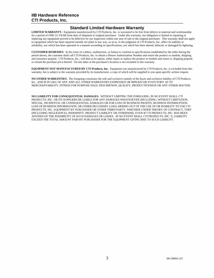
1. Introduction The Input/Output Interface Module (IIB) is a member of the Monitoring and Control Network (MCN™) family of User Interface Modules. Hardware specifications, special installation, and configuration information are described in this manual. The IIB module connects a parallel operator display device (such as a console) to the MCN network. The IIB is used with the operator display device and a Comparator I/O Module (such as a CIB or AIB) to create a comparator display system. The comparator display system provides monitoring and control functions for your communications system. Receiver states monitored by the IIB include VOTE, RECEIVE, DISABLE and FAIL. Receiver functions that can be controlled include FORCE VOTE and DISABLE.
897 ABC
D
EF012345
6897 AB
CD
EF012345
6897 AB
CD
EF012345
6
CA-80023-125
1 2 3 4ON
J1
E1 A
E1 BRESET
MODULEGROUP
PWR ACTERR
IN NETWORK OUT
DC IN
OPTION
Front View Rear View
Figure 1 - IIB Front and Rear View
1.1 Reference Documents 1. Monitoring and Control Network System Manual Part Number S2-60425

IIB Hardware Reference Specifications CTI Products, Inc.
7 68-10844-125
2. Specifications Size 5.5” x 4.2” x 1.5” (140 x 107 x 38
mm) Weight 16 oz (455 gm) Temperature 0 - 50 ºC Humidity 10 - 95% non-condensing Module Power 10 - 32 Vdc / 2 Watts max. Number of Receivers Supported 8 (Link Fail feature disabled)
7 (Link Fail feature enabled) Open Circuit Voltage (all I/O pins) jumper E1B removed jumper E1B installed
+13.8 Vdc nominal +5 Vdc nominal
Inputs per Receiver active low, pull-up to +5 or +13.8 Vdc
Force Vote, Disable
Input Voltage (Input and In/Out pins) -0.6 to 30 Vdc (max) Input Current (Input and In/Out pins): jumper E1B removed (Vin = 0 Vdc) jumper E1B installed (Vin = 0 Vdc)
-720 µA max (source) -270 µA max (source)
Outputs per Receiver (active low) Vote, Receive, Disable, Fail Output Saturation Voltage (Outputs and In/Out pins) with Iout = 100 mA
550 mV
Output Pin Current (Outputs and In/Out pins)
100 mA max per individual pin (sink) 90 mA max per pin if all outputs are ON.
Maximum Power Dissipation 2 Watts Input/Output Connection 50 pin Telco style Network Connector (2) RJ-45 (1 in, 1 out) Safety Approvals UL 1950
CSA 1950 EN 60950-1992
Emissions Compliance FCC Part 15, Class A DOC Class A EN55022
Susceptibility Compliance IEC 801-2 IEC 801-3 IEC 801-4 EN50082-1
Table 1 - Module Specifications

IIB Hardware Reference Specifications CTI Products, Inc.
8 68-10844-125
3. Typical I/O Circuitry Figure 2 shows the equivalent circuits of the IIB I/O pins. The pull-up voltage Vp by jumper E1B, located on the rear of the module.
• Vp = 13.8 Vdc with jumper E1B out • Vp = 5.0 Vdc with jumper E1B in
CA-80043-100
0.1uF
22K
Vp
150K
HCMOSIC
INPUT
PROTECTIONESD
30VTRANSORB
0.1uF
22K
Vp
PROTECTIONESD
30VTRANSORB
180K
+5V
0.1uF
22K
Vp
150K
HCMOSIC
INPUT
PROTECTIONESD
30VTRANSORB
+5V
+5V
INPUT/OUTPUT
OUTPUT
INPUT
Figure 2 - I/O Equivalent Circuit

IIB Hardware Reference Theory of Operation CTI Products, Inc.
9 68-10844-125
4. Theory of Operation This section describes the operation of the IIB module in an MCN comparator display system.
4.1 Comparator Status The Comparator I/O Module (such as an AIB or CIB) accepts the VOTE, RECEIVE, DISABLE, and FAIL receiver status indicators from the comparator. It sends status messages to the IIB module. The IIB module controls the VOTE, RECEIVE, DISABLE, and FAIL parallel lines of the operator interface (such as a console).
4.2 Controlling the Comparator The IIB module monitors the VOTE and DISABLE lines from the console. When the console activates a VOTE or DISABLE line, the IIB module will send a FORCE VOTE or DISABLE command to the comparator. The Comparator I/O Module will then generate the proper FORCE VOTE or DISABLE/ENABLE signal to control the comparator.
4.3 Associating an IIB with a Comparator I/O Modul e When an IIB is installed into a system, you need to configure the IIB with the address of the Comparator I/O Module it will be operating with. Section 8.1 describes how to enter this extra address. By having the address of the Comparator I/O Module (CIB or AIB module), the IIB knows how to route its control messages for FORCE VOTE and DISABLE over the MCN network.
4.4 System Example Figure 3 shows an example comparator display system using the IIB module with a console for the operator station.
CA-80034-100
MODULEIIB
COMPARATORI/OCONSOLE
ELECTRONICS
COMPARATORMCN NETWORK
CONSOLE
Figure 3 - IIB System Example
When the comparator detects that a receiver is active, it sends a RECEIVE command followed by a VOTE command (if that receiver becomes voted). The Comparator I/O Module processes these commands and sends them to the IIB. The IIB then activates the VOTE and RX outputs for that receiver.

IIB Hardware Reference Theory of Operation CTI Products, Inc.
10 68-10844-125
If the comparator detects that a receiver has failed, it sends a FAIL command to the Comparator I/O Module. Again, the Comparator I/O Module sends this FAIL command to the IIB so that the user can see that the receiver has failed. From the console, the user can generate FORCE VOTE or DISABLE commands for each receiver in the system. The IIB detects these active signals and sends them to the Comparator I/O Module, which then controls the comparator.
4.5 Receiver Banks The IIB module is designed to operate with a maximum of 8 receivers. This group of 8 receivers is called a bank. If the Comparator I/O Module supports more than 8 receivers (more than 1 bank of receivers), then multiple IIBs are required to monitor and control these additional banks. Section 5 describes how the IIB is configured to select the bank of receivers being monitored. For example, the system shown in Figure 4 shows an ASTRO-TAC™ Comparator that supports a total of 13 receivers. The AIB Comparator I/O Module separates the 13 receivers into two banks of 8 receivers.
CA-80044-100
OUT
P/S
IN
IN
OUT
TT
COMPARATORCONSOLEELECTRONICS
IN
OUT
AIBASTRO-TAC
13 RECEIVERS
IIBBANK 0
IIBBANK 1
CONSOLE
Figure 4 - Multiple IIB System Example
Two IIBs provide support for the 13 receivers of the ASTRO-TAC™ Comparator. The AIB module divides the 13 receivers into bank 0 (receivers 1 through 8) and bank 1 (receivers 9 through 13). Each IIB has to be configured to operate with one of the banks of the AIB. The first IIB would be configured to operate with bank 0 of the AIB. The other IIB would be configured to operate bank 1 of the AIB. This configuration is done using the option switches on the front of the IIB. Refer to section 5 for details. With this configuration, the console will be able to monitor and control receivers 1 through 13 of the comparator. The Link Fail feature of the second IIB (configured for bank 1) can be enabled to monitor the status of the AIB to ASTRO-TAC™ Comparator communication link as well as the MCN network communications link. Refer to section 9.1. Because the second IIB only monitors and controls receivers 9 through 13 (a total of 5 receivers) of the ASTRO-TAC™ Comparator, its highest receiver is unused and therefore available to display Link Fail status.

IIB Hardware Reference Theory of Operation CTI Products, Inc.
11 68-10844-125
4.6 Parallel I/O Signals The IIB provides two input/output lines per receiver (VOTE and DISABLE) that allow both monitoring and control of the signal. Two output only lines per receiver (FAIL and RECEIVE) are also provided. None of these I/O lines are latched in the IIB. In the console, the VOTE switch or button should be momentary, and the DISABLE switch or button should be latched. Because the VOTE and DISABLE lines are input/output lines, when the VOTE or DISABLE input is driven by the console, any device tied to that line will also be driven (an LED for example).
4.7 Bi-directional Lines Because the console VOTE and DISABLE lines are bi-directional, the console’s LEDs will be lit if the console outputs are active. Because of this, the console could still indicate a DISABLE or VOTE on a receiver even if there is a problem in the network cabling or the Comparator I/O Module. This is one reason for using the Link Failure Reporting of the IIB (see section 9.1, Link Failure Reporting). Using this feature, the operator can be warned when the comparator is not communicating with the Comparator I/O Module (provided the Comparator I/O Module supports Link Fail reporting) or when the IIB is not communicating with the CIB Comparator I/O Module.

IIB Hardware Reference Theory of Operation CTI Products, Inc.
12 68-10844-125
4.8 Example Connections to a Console Figure 5 shows how an IIB may be connected to a console. Notice that the VOTE and DISABLE lines between the IIB and the console are bi-directional.
CA-80049-100
+V
+V
MOMENTARY
+V
+V
LATCHING
CONSOLE ELECTRONICS IIB J1
VOTE
FAIL
RX
DISABLE
Figure 5 - IIB Connections to a Console

IIB Hardware Reference Option Switches CTI Products, Inc.
13 68-10844-125
4.9 Operation with a CIB as a Logic Repeater / Ext ender An IIB module can be used with a CIB module to provide a Logic Repeater/Extender function. This configuration allows logic signals at a CIB module to be sent over the MCN network to a remote IIB module (and vice versa). Each receiver in the CIB has (4) signal lines (a total of 32 lines in the CIB).
• The CIB can send data from all four lines to the IIB. • The CIB will accept signals from the IIB on only the Vote and Dis lines.
Although the Vote and Dis lines can be used as bi-directional lines, it is recommended that you use each line in one direction only. Contact the factory for applications assistance when using the lines in bidirectional mode.
CIB Function Dir IIB Function Vote/Mon 1 <---> Vote 1 Rx 1 -----> Rx 1 Dis 1 <---> Dis 1 Fail 1 -----> Fail 1
Table 2 – CIB to IIB Signal Direction
The CIB module must be used in the "Spectra-TAC mode" for this application (Switches 1 & 2 Down). Each of the 8 receiver sections is similar.
CAUTION Do not operate a CIB or IIB module with any system that has signal
levels that go below ground level!
Damage to the module can result and will void the w arranty.

IIB Hardware Reference Option Switches CTI Products, Inc.
14 68-10844-125
5. Switches & Jumpers Three sets of option switches are provided for module configuration. The module must be power cycled or reset after these switches are set so that the options will take effect. Table 3 describes the option switches and shows the factory defaults.
SWITCH DESCRIPTION DEFAULT GROUP unit address setting (00 – FE)
refer to the MCN System Manual 00
MODULE unit address setting (0-F) refer to the MCN System Manual
0
OPTION position 1
receiver bank selector 1 (see Table 4)
DOWN
position 2 receiver bank selector 2 (see Table 4) DOWN position 3 receiver bank selector 3 (see Table 4) DOWN position 4 unit address selector DOWN
Table 3 - IIB Option Switches
5.1 Group & Module Switches The Group and Module selector switches are used to set the unit address during module installation. Refer to the Monitoring and Control Network System Manual (or the Custom System documentation if shipped with your system) for details about planning the Group and Module addresses for the modules in your system. The IIB needs two sets of Group & Module addresses to be configured for proper operation:
• The address of the CIB or AIB module it is associated with and • The IIB's own address.
Option Switch 4 is used to set the address of the associated CIB or AIB. Refer to section 8, Special Installation Instructions, for step-by-step instructions of this procedure.

IIB Hardware Reference Option Switches CTI Products, Inc.
15 68-10844-125
5.2 Option Switches The unit address selector switch (OPTION switch position 4) is only used at installation time. Refer to section 8, Special Installation Instructions, for a description of this switch. For normal operation, this switch must be in the DOWN position.
An IIB can monitor 8 receivers when the Link Fail feature is disabled or 7 receivers when the Link Fail feature is enabled (one receiver bank). Option switches 1 through 3 allow the IIB to monitor any receiver bank supported by the Comparator I/O Module. The settings for these switches are shown in Table 4. If the Link Fail feature is enabled, the last receiver on an IIB is unusable. The IIB will not provide monitoring and control functions for that receiver.
Bank Option Switch Position
1 2 3 Receiver Numbers
0 DOWN DOWN DOWN 1 through 8 1 UP DOWN DOWN 9 through 16 2 DOWN UP DOWN 17 through 24 3 UP UP DOWN 25 through 32 4 DOWN DOWN UP 33 through 40 5 UP DOWN UP 41 through 48 6 DOWN UP UP 49 through 56 7 UP UP UP 57 through 64
Table 4 - Receiver Bank Selectors When the IIB is used with a Comparator I/O Module that supports only 8 receivers, such as a CIB, bank 0 will always be used.

IIB Hardware Reference Option Switches CTI Products, Inc.
16 68-10844-125
5.3 Inactivity Output Release (IOR) Feature An Inactivity Output Release (IOR) feature was added in IIB Modules version 180 and up. This feature is used for special CIB-IIB Logic Repeater/Extender applications. This feature is normally not used in comparator applications. The Inactivity Output Release feature turns off the IIB outputs when the IIB loses communications with its companion CIB module. When the IIB loses communications, the Activity LED will turn off within about 20 seconds. The IIB will then turn off all its outputs and let them be pulled high. The Inactivity Output Release feature may be turned on & off in the IIB module as follows:
1. Record the setting of the Group & Module switches and Option Switch 1. 2. Set the Group & Module address to FF:F. 3. Set Option Switch 1 as follows:
On Enable Inactivity Output Release function Off Disable Inactivity Output Release function
4. Press the Reset switch. 5. The IIB Error LED will turn on. 6. Reset the Group:Module switches and the Option Switch 1 to the proper
settings for your system 7. Press the Reset switch. (The ERR LED should go off.)
The state of the Inactivity Output Release feature is indicated on the ACT LED as described below: ACT LED State IOR Feature Connected with CIB Not Connected with CIB Disabled Solid On (normal) Solid Off (normal) Enabled Normally On with
50 ms Off pulse every 3 seconds
Normally Off with 50 ms On pulse every 3 seconds
Thus, if the IOR feature is disabled, the ACT LED functions normally. If the feature is enabled, you will see a short pulse every 3 seconds. When using the IOR feature (with a CIB and IIB) be sure not to have a PC monitor the CIB module, since the CIB will see this as a connection (and the ACT LED will be enabled).

IIB Hardware Reference Option Switches CTI Products, Inc.
17 68-10844-125
5.4 Jumper Options Figure 6 shows the configuration of the two jumper options available on the rear of the IIB. These jumpers should be installed at system installation time with power removed from the IIB.
CA-80024-100
E1 A
E1 B
Figure 6 - Jumper Options
Jumper E1A is located across the top 2 terminals of the 6 pin terminal block. This jumper must normally be installed. It is only removed for factory test. Jumper E1B is located across the left side middle and bottom terminals of the 6 pin terminal block. Set this jumper to match the needs of your operator interface station. The remaining 2 terminals of the block are unused.
Jumper Function Default
E1A In to enable output RX 7. Out to disable output RX 7.
IN
E1B Vp Set
In for inputs pulled up to +5 Vdc. Out for inputs pulled up to +13.8 Vdc.
OUT
Figure 7 - Jumper Options Description
Because most installations require the pull-up voltage to be +13.8 Vdc, no jumper is provided with the unit for the E1B jumper terminals. If you have an application that requires the pull-up voltage to be set to +5 Vdc, you can order an additional jumper by calling CTI Products Inc. and ordering part number 27-10351.

IIB Hardware Reference Connectors CTI Products, Inc.
18 68-10844-125
6. LED Indicators The IIB module has three LED indicators on the front panel.
897 A BC
D
EF012345
6897 AB
CD
EF012345
6897 AB
CD
EF012345
6
1 2 3 4ON
RESET
MODULEGROUP
PWR ACTERR
IN NETWORK OUT
DC IN
OPTION
Front View
PWR On when sufficient power is present Blinks when the voltage is low. ERR On when there is an error in the module. It is also on when the Group switches have been set to FF. (FF is an invalid MCN group.) ACT On when the IIB module is connected to an associated CIB or AIB module. IIB Version 180 & above: This LED will also blink (on or off) for 50 ms every 3 seconds if the IOR function is enabled.

IIB Hardware Reference Connectors CTI Products, Inc.
19 68-10844-125
7. Connectors
7.1 Network In/Out Connectors The NETWORK IN/OUT ports on the front of the IIB are used to connect the IIB with other MCN modules. These ports carry both the network data signals as well as DC power for power distribution with other modules. . Table 5 gives the pinout for these connectors. Figure 8 shows the location of pin 1 for each port.
CA-80068-100
DC IN
IN OUTNETWORK
PRODUCTS, INC.
PIN 1
Figure 8 - Network IN/OUT Ports
Pin Function 1 DATA + 2 DATA - 3 + POWER 4 No Connect 5 No Connect 6 - POWER 7 - POWER 8 + POWER
Table 5 - Network Connector Pinout
The DC IN port provides the primary power connection to the module. Power is distributed through the NETWORK OUT connector to provide power to the NETWORK IN connector of the MCN unit it is connected to. Each power supply can power up to four units total. See reference 1 for complete details of connections to the network and DC IN connectors.

IIB Hardware Reference Connectors CTI Products, Inc.
20 68-10844-125
7.2 J1 50-Pin I/O Connector Connector J1 on the rear of the unit provides the discrete I/O for the receiver signals.
CA-80023-125
J1
E1 A
E1 B
Rear View
Figure 9 describes the functions of the per-receiver I/O signals. All inputs and outputs are active low.
Signal Direction Description VOTE Input/Output Output activated when comparator votes that receiver.
Ground input to force vote a receiver. RX Output Activated when comparator detects a valid signal on
the receiver. DIS Input/Output Output activated when receiver is disabled by
comparator. Ground input to disable the receiver.
FAIL Output Activated when receiver failure is detected by the comparator.
Figure 9 – Per Receiver I/O signal descriptions
Figure 10 lists the functions of the per-receiver I/O signals. All inputs and outputs are active low.
Signal Direction Description Link Fail Enable
(LFE) Input Low to enable Link Status Reporting
Link Fail Invert (LFI)
Input Low to invert the polarity of the Link Fail output.
Fail 8 / Link Fail (LF)
Output Output indicates state of the link between the IIB and the CIB or AIB.
Figure 10 – Common Control & Status I/O signal descriptions
See section 9, Special Features, for details on the operation of the above signals for Link Failure Reporting.

IIB Hardware Reference Connectors CTI Products, Inc.
21 68-10844-125
Table 6 gives the pinout for this connector. IIB J1 Function Direction Wire Color
21 Vote 1 Input/Output Blu/Vio 19 Rx 1 Output Brn/Yel 20 Dis 1 Input/Output Slt/Yel 23 Fail 1 Output Grn/Vio 46 Vote 2 Input/Output Vio/Blu 44 Rx 2 Output Yel/Brn 45 Dis 2 Input/Output Yel/Slt 48 Fail 2 Output Vio/Grn 15 Vote 3 Input/Output Slt/Blk 12 Rx 3 Output Org/Blk 14 Dis 3 Input/Output Brn/Blk 17 Fail 3 Output Org/Yel 40 Vote 4 Input/Output Blk/Slt 37 Rx 4 Output Blk/Org 39 Dis 4 Input/Output Blk/Brn 42 Fail 4 Output Yel/Org 9 Vote 5 Input/Output Brn/Red 6 Rx 5 Output Blu/Red 8 Dis 5 Input/Output Grn/Red 11 Fail 5 Output Blu/Blk 34 Vote 6 Input/Output Red/Brn 31 Rx 6 Output Red/Blu 33 Dis 6 Input/Output Red/Grn 36 Fail 6 Output Blk/Blu 3 Vote 7 Input/Output Grn/Wht 18 Rx 7 Output Grn/Yel 2 Dis 7 Input/Output Org/Wht 5 Fail 7 Output Slt/Wht 28 Vote 8 Input/Output Wht/Grn 26 Rx 8 Output Wht/Blu 27 Dis 8 Input/Output Wht/Org 30 Fail 8 / Link Fail Output Wht/Slt 4 Link Fail Enable (LFE) Input Brn/Wht 29 Link Fail Invert (LFI) Input Wht/Brn 1 Ground Blu/Wht 10 unused Input Slt/Red 16 unused Input Blu/Yel 22 unused Input Org/Vio 35 unused Input Red/Slt 41 unused Input Yel/Blu 47 unused Input Vio/Org 7 unused No Connect Org/Red 13 unused No Connect Grn/Blk 24 unused No Connect Brn/Vio 25 unused No Connect Slt/Vio 32 unused No Connect Red/Org 38 unused No Connect Blk/Grn 43 unused No Connect Yel/Grn 49 unused No Connect Vio/Brn 50 unused No Connect Vio/Slt
Table 6 - IIB Connector J1 Pinout in ‘Logic’ Order

IIB Hardware Reference Connectors CTI Products, Inc.
22 68-10844-125
IIB J1 Function Direction Wire Color
26 Rx 8 Output Wht/Blu 1 Ground Blu/Wht 27 Dis 8 Input/Output Wht/Org 2 Dis 7 Input/Output Org/Wht 28 Vote 8 Input/Output Wht/Grn 3 Vote 7 Input/Output Grn/Wht 29 Link Fail Invert (LFI) Input Wht/Brn 4 Link Fail Enable (LFE) Input Brn/Wht 30 Fail 8 / Link Fail Output Wht/Slt 5 Fail 7 Output Slt/Wht 31 Rx 6 Output Red/Blu 6 Rx 5 Output Blu/Red 32 unused No Connect Red/Org 7 unused No Connect Org/Red 33 Dis 6 Input/Output Red/Grn 8 Dis 5 Input/Output Grn/Red 34 Vote 6 Input/Output Red/Brn 9 Vote 5 Input/Output Brn/Red 35 unused Input Red/Slt 10 unused Input Slt/Red 36 Fail 6 Output Blk/Blu 11 Fail 5 Output Blu/Blk 37 Rx 4 Output Blk/Org 12 Rx 3 Output Org/Blk 38 unused No Connect Blk/Grn 13 unused No Connect Grn/Blk 39 Dis 4 Input/Output Blk/Brn 14 Dis 3 Input/Output Brn/Blk 40 Vote 4 Input/Output Blk/Slt 15 Vote 3 Input/Output Slt/Blk 41 unused Input Yel/Blu 16 unused Input Blu/Yel 42 Fail 4 Output Yel/Org 17 Fail 3 Output Org/Yel 43 unused No Connect Yel/Grn 18 Rx 7 Output Grn/Yel 44 Rx 2 Output Yel/Brn 19 Rx 1 Output Brn/Yel 45 Dis 2 Input/Output Yel/Slt 20 Dis 1 Input/Output Slt/Yel 46 Vote 2 Input/Output Vio/Blu 21 Vote 1 Input/Output Blu/Vio 47 unused Input Vio/Org 22 unused Input Org/Vio 48 Fail 2 Output Vio/Grn 23 Fail 1 Output Grn/Vio 49 unused No Connect Vio/Brn 24 unused No Connect Brn/Vio 50 unused No Connect Vio/Slt 25 unused No Connect Slt/Vio
Table 7 - IIB Connector J1 Pinout in ‘Punch Block’ Order

IIB Hardware Reference Special Installation Inst ructions CTI Products, Inc.
23 68-10844-125
8. Special Installation Instructions
8.1 Unit Address Setting An IIB must be programmed with two unit addresses:
1. the address of the Comparator I/O Module it will operate with and 2. the IIB’s own address
You only need to perform this programming once, at installation time. These addresses are stored in non-volatile memory so the only reason that you would have to repeat this step is if you changed the unit address of the Comparator I/O Module or if you replaced the IIB module. Before programming the address information into the IIB, determine the unit addresses of all the MCN modules in the system, following the guidelines in the Address Planning section of the Monitoring and Control Network System Manual (reference 1). Valid ranges for the Group and Module switches are:
• Group number = 00 through FE • Module number = 0 through F
The steps for programming the unit address of the Comparator I/O Module are:
Step Action 1 Determine the unit addresses of all the MCN modules in the system. 2 Apply power to the IIB. 3 Place OPTION switch 4 in the UP position. 4 Set the Group and Module switches to the unit address of the
Comparator I/O Module (from step 1) that this IIB will operate with. 5 Press the RESET button on the IIB. 6 The ERR LED will turn on and remain on. 7 Place OPTION switch 4 in the DOWN position. 8 Set the Group and Module switches to the unit address of this IIB
(its own address from step 1). 9 Press the RESET button on the IIB. 10 The ERR LED will turn on momentarily and then turn off.
After you complete these steps, connect the IIB to the Comparator I/O Module. Apply power to the Comparator I/O Module and within approximately three seconds, the ACT LED of the IIB should turn on and the ACT LED of the Comparator I/O Module should turn on or blink. If the ACT LEDs turn on, the IIB has been correctly programmed with the unit address of the Comparator I/O Module. If the ACT LEDs remain off, verify your unit switch settings and repeat the unit address programming steps.
IIB Hardware Reference Special Installation Inst ructions CTI Products, Inc.
24 68-10844-125
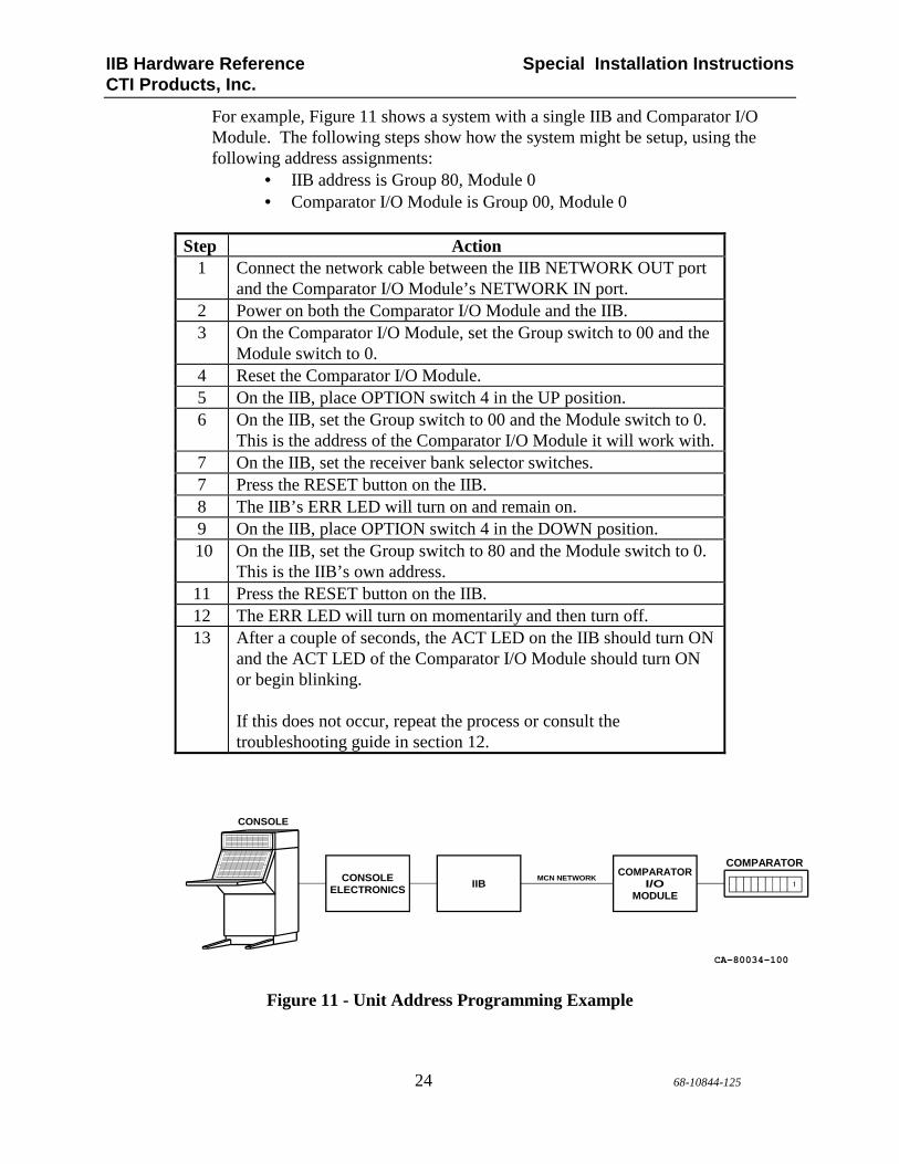
For example, Figure 11 shows a system with a single IIB and Comparator I/O Module. The following steps show how the system might be setup, using the following address assignments:
• IIB address is Group 80, Module 0 • Comparator I/O Module is Group 00, Module 0
Step Action
1 Connect the network cable between the IIB NETWORK OUT port and the Comparator I/O Module’s NETWORK IN port.
2 Power on both the Comparator I/O Module and the IIB. 3 On the Comparator I/O Module, set the Group switch to 00 and the
Module switch to 0. 4 Reset the Comparator I/O Module. 5 On the IIB, place OPTION switch 4 in the UP position. 6 On the IIB, set the Group switch to 00 and the Module switch to 0.
This is the address of the Comparator I/O Module it will work with. 7 On the IIB, set the receiver bank selector switches. 7 Press the RESET button on the IIB. 8 The IIB’s ERR LED will turn on and remain on. 9 On the IIB, place OPTION switch 4 in the DOWN position.
10 On the IIB, set the Group switch to 80 and the Module switch to 0. This is the IIB’s own address.
11 Press the RESET button on the IIB. 12 The ERR LED will turn on momentarily and then turn off. 13 After a couple of seconds, the ACT LED on the IIB should turn ON
and the ACT LED of the Comparator I/O Module should turn ON or begin blinking. If this does not occur, repeat the process or consult the troubleshooting guide in section 12.
CA-80034-100
MODULEIIB
COMPARATORI/OCONSOLE
ELECTRONICS
COMPARATORMCN NETWORK
CONSOLE
Figure 11 - Unit Address Programming Example

IIB Hardware Reference Special Features CTI Products, Inc.
25 68-10844-125
9. Special Features
9.1 Link Failure Reporting The IIB has a selectable option to show communication link failures between the IIB and its Comparator I/O Module (network link failures) or between the Comparator I/O Module and the comparator (comparator link failures). With this option enabled, the IIB will report network link failures. This option is enabled with the following two input pins: J1 Pin Signal Notes
4 Link Fail Enable (LFE)
Ground to enable Link Fail Indication
29 Link Fail Invert (LFI)
Ground to invert the sense of the Link Fail pin This function was added in IIB version 175
Both these inputs are sensed only on power-up and reset. LFE Pin 4
LFI Pin 29
Link Condition
Fail 8 / Link Fail Output Pin 30
Notes
Open X X Standard Fail 8 function Gnd Open Link Good High Gnd Open Link Bad Low (Ground) Gnd Gnd Link Good Low (Ground) Rev 175 & Up Gnd Gnd Link Bad High Rev 175 & Up
"X" indicates a don't-care condition. A "Link Bad" condition can be any of the following failures:
• CIB to IIB link failure • AIB to IIB link failure • AIB to Astrotac comparator serial link failure

IIB Hardware Reference Special Features CTI Products, Inc.
26 68-10844-125
9.2 Receiver 8 Signals when using Link Failure Rep orting Since the Link Fail and Fail 8 signals share a pin, when the Link Fail feature is enabled, the Fail 8 signal is not passed from the CIB or AIB to the output of the IIB. The operation of the Vote 8, Rx 8, and Dis 8 pins vary with the IIB version: IIB Version
Vote 8, Rx 8, Dis 8 Operation with Link Fail Reporting
pre 175 Inactive (high) 175 & up Active when connecting the IIB to a CIB The older version of the IIB masked out the Vote, RX, and Dis lines of receiver 8 if the Link Failure Reporting is used. Version 175 and up allow those lines to be used for systems that are using CIBs & IIBs in logic repeater / extender functions.
9.3 AIB – Astrotac Link Failure Reporting When the IIB is used with an AIB module, the Link Fail signal will also indicate a failure of the AIB to Astrotac comparator serial link. The Link Fail output will show Fail when either the AIB to IIB link is failed or the AIB to Astrotac comparator link is failed

IIB Hardware Reference Mounting CTI Products, Inc.
27 68-10844-125
10. Mounting Refer the reference 1, section Mounting Options, for details about mounting the IIB module.
CAUTION Make sure that any mounting screws used to secure unit to a bracket do not protrude into the unit’s enclosure more than 1/8 inches from the bottom surface of the unit. Using a larger screw that touches the pc board inside the unit may damage the unit when it is powered. Doing so will void the unit’s warranty.

IIB Hardware Reference Connecting an IIB to a CEB CTI Products, Inc.
28 68-10844-125
11. Connecting an IIB to a CEB The following example shows how you would connect an IIB to Motorola’s CEB (Central Electronics Bank) in a comparator display system. Figure 12 shows what this system looks like.
CA-80029-100
COMPARATOROUT
IN
T
IN
OUT
MODULE
MCN
1
COMPARATOR16 I/O
CEB
RX1-4
RX5-8
IIB
P/S
A
16 I/OB
T
I/O
Figure 12 - IIB / CEB Connection Example
The IIB connects to the CEB through two 16 I/O cards (cards A and B). Each 16 I/O card can handle only 4 receivers. The CEB must be configured so that the 16 I/O cards operate as comparator display boards. Table 8 shows the cross connections needed between the IIB and the 16 I/O cards. Once these connections are made, you need to install jumper JU6 through JU33 on each 16 I/O card. Please note that the IIB does not connect directly to a 16-I/O board; the pinouts are different. You must cross-connect using punch blocks.

IIB Hardware Reference Connecting an IIB to a CEB CTI Products, Inc.
29 68-10844-125
IIB J1
Function Connect to 16 I/O Bd (A or B) - Pin
21 Vote 1 A – 26
19 Rx 1 A – 27
20 Dis 1 A – 28
23 Fail 1 A – 29
46 Vote 2 A – 30
44 Rx 2 A – 31
45 Dis 2 A – 32
48 Fail 2 A – 33
15 Vote 3 A – 34
12 Rx 3 A – 35
14 Dis 3 A – 36
17 Fail 3 A – 37
40 Vote 4 A – 38
37 Rx 4 A – 39
39 Dis 4 A – 40
42 Fail 4 A – 41
9 Vote 5 B – 26
6 Rx 5 B – 27
8 Dis 5 B – 28
11 Fail 5 B – 29
34 Vote 6 B – 30
31 Rx 6 B – 31
33 Dis 6 B – 32
36 Fail 6 B – 33
3 Vote 7 B – 34
18 Rx 7 B – 35
2 Dis 7 B – 36
5 Fail 7 B – 37
28 Vote 8 B - 38 *
26 Rx 8 B - 39 *
27 Dis 8 B - 40 *
30 Fail 8 / Link Fail B - 41 *
4 Link Fail Enable connect to IIB J1 pin 1 to enable the Link Fail feature
29 Link Fail Invert (LFI)
connect to IIB J1 pin 1 to invert the Link Fail polarity
1 Ground A & B 1 through 16
Table 8 - IIB to CEB Connections
* Signals for receiver 8 are active only if the Link Fail Enable (J1 pin 4) is open (Link Fail feature is disabled). If J1 pin 4 is grounded, J1 pin 30 becomes a Link Fail output and J1 pins 26, 27 and 28 become unused pins.
IIB Hardware Reference Troubleshooting CTI Products, Inc.
30 68-10844-125
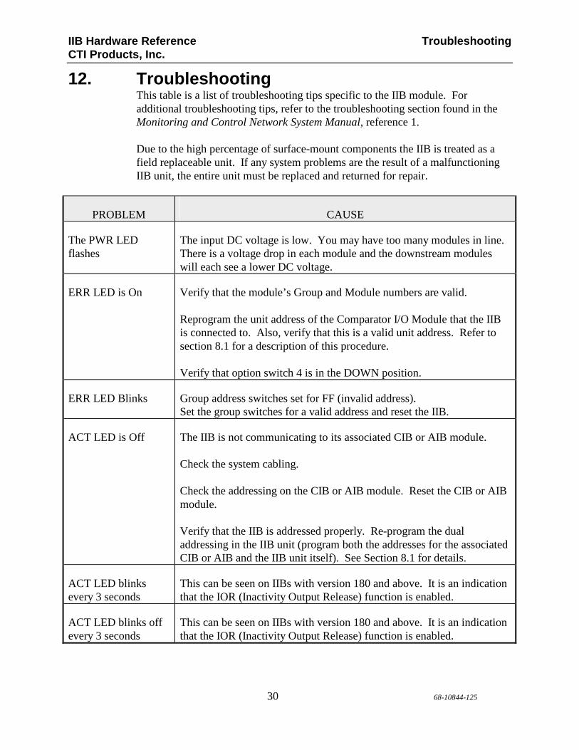
12. Troubleshooting This table is a list of troubleshooting tips specific to the IIB module. For additional troubleshooting tips, refer to the troubleshooting section found in the Monitoring and Control Network System Manual, reference 1. Due to the high percentage of surface-mount components the IIB is treated as a field replaceable unit. If any system problems are the result of a malfunctioning IIB unit, the entire unit must be replaced and returned for repair.
PROBLEM CAUSE
The PWR LED flashes
The input DC voltage is low. You may have too many modules in line. There is a voltage drop in each module and the downstream modules will each see a lower DC voltage.
ERR LED is On Verify that the module’s Group and Module numbers are valid. Reprogram the unit address of the Comparator I/O Module that the IIB is connected to. Also, verify that this is a valid unit address. Refer to section 8.1 for a description of this procedure. Verify that option switch 4 is in the DOWN position.
ERR LED Blinks Group address switches set for FF (invalid address). Set the group switches for a valid address and reset the IIB.
ACT LED is Off The IIB is not communicating to its associated CIB or AIB module. Check the system cabling. Check the addressing on the CIB or AIB module. Reset the CIB or AIB module. Verify that the IIB is addressed properly. Re-program the dual addressing in the IIB unit (program both the addresses for the associated CIB or AIB and the IIB unit itself). See Section 8.1 for details.
ACT LED blinks every 3 seconds
This can be seen on IIBs with version 180 and above. It is an indication that the IOR (Inactivity Output Release) function is enabled.
ACT LED blinks off every 3 seconds
This can be seen on IIBs with version 180 and above. It is an indication that the IOR (Inactivity Output Release) function is enabled.

IIB Hardware Reference Troubleshooting CTI Products, Inc.
31 68-10844-125
PROBLEM CAUSE
Receiver 8 is not working properly
Verify that the Link Fail Enable pin (J1, pin 4) is not tied to ground when the module is reset.
Link Failure Reporting is not working properly
Verify that the Link Fail Enable pin (J1, pin 4) is tied to ground when the module is reset. Verify that the Link Fail Invert pin (J1 pin 29) is wired properly for the polarity desired on the Link Fail output. See section 9 for details.
Link Fail Enable (J1 pin 4) is grounded and the Link Fail output (J1 pin 30) is active.
Verify that the network cable between the IIB and the Comparator I/O module is properly connected and that both modules are communicating (their ACT LEDs are on).
If you are using an AIB module, verify that the cable between the AIB module and the Astrotac comparator I/O and the AIB module is communicating with the comparator (refer to the troubleshooting section of the AIB Module manual).


![10844 - senate.gov.ph 10844.pdf · 10844] AN ACT CREATING THE DEPARTMENT OF INFORMATION AND COMMUNICATIONS TECHNOLOGY. DEFINING ITS POWERS AND FUNCTIONS, APPROPRIATING FUNDS THEREFOR.](https://static.fdocuments.in/doc/165x107/5c41c08993f3c338be306d9b/10844-10844pdf-10844-an-act-creating-the-department-of-information-and-communications.jpg)