
UE-12-09 Ultra Fiber Optic Selector Guidege fanuc genius bus™/ remote i/o reliance r-net™/...
6
Fiber Optic Selector Guide for PLC & Serial Communication Networks Electrical Interface Modules Optical Interface Modules Power Supply Modules Self-Healing Ring Modules www.ultra-nspi.com
Transcript of UE-12-09 Ultra Fiber Optic Selector Guidege fanuc genius bus™/ remote i/o reliance r-net™/...

Fiber Optic Selector Guide for PLC & Serial Communication Networks
Electrical Interface Modules
Optical Interface Modules
Power Supply Modules
Self-Healing Ring Modules
www.ultra-nspi.com
Ultra Electronics 2
Fiber Optic Selector Guide for PLC & Serial Communication Networks
2C21
2C23
2C30
DEVICENET
PROFIBUS-DP W/ 24VDC POWER
GE GENIUS, R-NET, MODICON REMOTE I/O,MODICON MODBUS PLUS,AB DH+, AB REMOTE I/O
125KBPS
ALL PROFIBUS DATA RATES
9.6K TO 2M BAUD FM APPROVED CLASS 1 DIVISION 2 GROUPS
A, B, C, D
BUILT INTO DEVICE
BUILT INTO DEVICE
2C02, 2C07, 2C12, 2C14,2C15, 2C29
2C30 - RELAY CONTACT RATING: 175VDC, 0.25A SWITCHING, 1A CONTINUOUS
PartNumber
NetworkProtocol
CommunicationsData Rate Certifications
Compatible Electrical Interface Modules
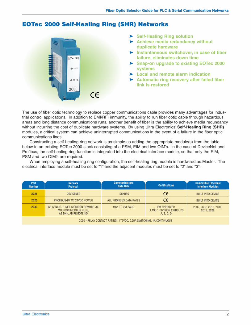
EOTec 2000 Self-Healing Ring (SHR) Networks
� Self-Healing Ring solution� Achieve media redundancy without
duplicate hardware� Instantaneous switchover, in case of fiber
failure, eliminates down time� Snap-on upgrade to existing EOTec 2000
systems� Local and remote alarm indication� Automatic ring recovery after failed fiber
link is restored
The use of fiber optic technology to replace copper communications cable provides many advantages for indus-trial control applications. In addition to EMI/RFI immunity, the ability to run fiber optic cable through hazardousareas and long distance communications runs, another benefit of fiber is the ability to achieve media redundancywithout incurring the cost of duplicate hardware systems. By using Ultra Electronics’ Self-Healing Ring (SHR)modules, a critical system can achieve uninterrupted communications in the event of a failure in the fiber opticcommunications lines.
Constructing a self-healing ring network is as simple as adding the appropriate module(s) from the tablebelow to an existing EOTec 2000 stack consisting of a PSM, EIM and two OIM’s. In the case of DeviceNet andProfibus, the self-healing ring function is integrated into the electrical interface module, so that only the EIM,PSM and two OIM’s are required.
When employing a self-healing ring configuration, the self-healing ring module is hardwired as Master. Theelectrical interface module must be set to “1” and the adjacent modules must be set to “2” and “3”.

GEFa
nuc
Rock
wel
l Aut
omat
ion
Schn
eide
r
GE FANUC GENIUSBUS™/ REMOTE I/O
RELIANCE R-NET™/REMOTE I/O
A-B DH & DH+™/REMOTE I/O
A-B DH-485™
MODICON REMOTEI/O
MODICON MODBUSPLUS™
RS-232/485
CONTROLNET™
DEVICENET™
PROFIBUS™
2C02
2C07
2C12
2C15
2C14
2C29
2C10
2C20
2C21
2C22
153.6K EXTENDED
800K
57.6K, 115.2K AND230.4K JUMPER
SELECTABLE
19.2K
1.54M
1.0M
RS-232: 9.6K-115K RS-485: 9.6K-230K HALF DUPLEX
5.0M
125K
ALL
SCREW TERMINAL, CAGE CLAMP
BNC
SCREW TERMINAL, CAGE CLAMP
SCREW TERMINAL, CAGE CLAMP
F-TYPE
DB-9 PIN
SCREW TERMINAL, CAGE CLAMP
BNC
5-POS DNET TERMINAL
DB-9 PIN
NONE
INTERNAL (75Ω)
NONE
NONE
INTERNAL (75Ω)
NONE
NONE
INTERNAL (75Ω)
NONE
NONE
32UNITS, 3500FT (1KM)
1UNIT, 200FT (50M)
60 UNITS, 10,000FT (3KM)
DH-485 SPECIFICATION 32DEVICES/4000FT.
20DB OF CABLE/TAP LOSS
MODICON MODBUS PLUS™
SPECIFICATION
RS-232: 1 UNIT, 50FT (15M) RS-485: 30 UNITS, 4000FT
(1.2KM)
CONTROLNET™ SPECIFICATION
DEVICENET™
SPECIFICATION
PROFIBUS™ SPECIFICATION
Open
Pro
toco
ls
EIM’s without internal termination can be used anywhere along a copper segment, whereas, modules with internal termination must be used at the end of copper segments only.
Baud Rate PhysicalInterface
Copper CableTermination
Max. Devices/Copper Cable Length per Module
Ultra Electronics3
Fiber Optic Selector Guide for PLC & Serial Communication Networks
EOTec 2000 Modular Fiber Optic Converters
� Transparent copper to fiber conversion� Modular, flexible, scalable� Real-time monitoring of fiber optic signal
strength� Protocol specific copper interface
connections� High Performance Deterministic
Technology � Full industrial operating temperature
range (-40 to +85 °C)� FM approved Class I, Div 2, Groups A, B,
C & D� Standard 35 mm DIN rail mounting
EIM Description andPart Number
EOTec 2000 Fiber Optic Converters are designed to take traditional copper networks, convert them to fiber opticsignals, and back again. Options support all popular fiber optic connectors (ST, SMA, SC). Problems such asground loops, EMI/RFI noise and lightning strikes are eliminated. Fiber optic communication links can also beextended over much greater distances and support physical topologies not available with copper networks.
Every fiber optic node requires• Electrical Interface Module (EIM)• Optical Interface Module (OIM)• Power Supply Module (PSM)
The Electrical Interface Module (EIM) is connected to the copper communication line. The module receivessignals from the copper link, conditions them and makes the signal available to the backplane for conversion.The EIM also accepts signals from the backplane and transmits the signal to the attached copper link. The usermust be sure to select the proper EIM for the copper protocol being converted.
Considerations when selecting an Electrical Interface Module (EIM)• What communication protocol is being converted?• What is the baud rate?

Fiber Optic Selector Guide for PLC & Serial Communication Networks
Ultra Electronics 4
2E06*
2D06*
2E07
2D07
2E10
2D10
2E09
2D09
2E19
2D19
2E36
2D36
2E46
2D46
850nm
850nm
850nm
850nm
850nm
850nm
1300nm
1300nm
1300nm
1300nm
1300nm
1300nm
1300nm
1300nm
9.6K to 12M
9.6K to 12M
9.6K to 12M
9.6K to 12M
9.6K to 12M
9.6K to 12M
9.6K to 12M
9.6K to 12M
9.6K to 12M
9.6K to 12M
9.6K to 12M
9.6K to 12M
9.6K to 12M
9.6K to 12M
SMA
SMA
ST
ST
ST
ST
ST
ST
ST
ST
ST
ST
ST
ST
21
21
2112211223172317
12
12
18
18
10
10
16
16
200/230
200/230
200/23062.5/125200/23062.5/125200/23062.5/125200/23062.5/125
62.5/125
62.5/125
62.5/125
62.5/125
8-10/125
8-10/125
8-10/125
8-10/125
No
Yes
No
Yes
No
Yes
No
Yes
No
Yes
No
Yes
No
Yes
OpticalConnector Type
OpticalDynamic Range (dB)
Applicable Fiber OpticCable Size/Type (µm)
Diagnostic Output (4-20mA)
OIM Type andPart Number
MUL
TIM
ODE
SING
LE M
ODE
Safety: IEC 60825-1 Class 1 LED PRoducts, FDA 21CFR1040.10 & 1040.11
Each 2E/2D OIM module can be set for high power or low power. Default jumper setting for the optical transmit power is “H” (high); this setting should not be adjusted unless an optical overdrive situation occurs. Select position “L” (Low) in overdriving conditions.
OpticalWavelength Baud Rate
EOTec 2000 Modular Optical Interface Modules
� Extend your network up to 30 km withouta repeater
� SMA or ST fiber connectors� Diagnostic Output (4-20mA)� Up to 5 optical modules per modem� Single/Multi-mode conversion possible� 850nm or 1300nm wavelength� High/Low power setting� Long lifetime - Class I LED
The Optical Interface Module (OIM) accepts a signal from the backplane, converts it to an optical signal, andtransmits this signal down the fiber optic cable. Conversely, the module will receive optical signals, condition thesignal and make it available to the backplane.
Considerations when selecting an Optical Interface Module (OIM)• Is the fiber optic cable single mode or multi-mode?• What types of connectors terminate the fiber optic cable? (ST or SMA)• What is the total loss on the fiber optic link? (This number must be less than the optical budget of the
OIM selected)• Is fiber link monitoring desirable?
* Not suitable for use with 2C20 ControlNet module
Fiber Optic Selector Guide for PLC & Serial Communication Networks
Ultra Electronics 5
2A06
2A16
2A08
2A18
85-240VAC 50/60Hz & 85-140VDC
85-240VAC 50/60Hz & 85-140VDC
24VDC (±10%)
24VDC (±10%)
250mA
250mA
400mA
400mA
400mA SLOW-BLOW
400mA SLOW-BLOW
400mA SLOW-BLOW
400mA SLOW-BLOW
NO
YES
NO
YES
YES/YES
YES/YES
YES/YES
YES/NO
NO
NO
YES
YES
ALARM RELAY CONTACT RATING: FORM-C, 175FDC, 1A CONTINUOUS
PartNumber Input Voltage Input
Current (Max.) Input Fuse AlarmRelay
CE Mark/UL
FM Approval Class I, Div. 2
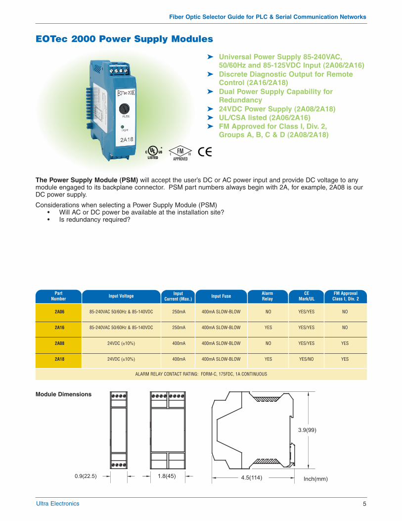
EOTec 2000 Power Supply Modules
� Universal Power Supply 85-240VAC,50/60Hz and 85-125VDC Input (2A06/2A16)
� Discrete Diagnostic Output for RemoteControl (2A16/2A18)
� Dual Power Supply Capability forRedundancy
� 24VDC Power Supply (2A08/2A18)� UL/CSA listed (2A06/2A16)� FM Approved for Class I, Div. 2,
Groups A, B, C & D (2A08/2A18)
The Power Supply Module (PSM) will accept the user’s DC or AC power input and provide DC voltage to anymodule engaged to its backplane connector. PSM part numbers always begin with 2A, for example, 2A08 is ourDC power supply.
Considerations when selecting a Power Supply Module (PSM)• Will AC or DC power be available at the installation site?• Is redundancy required?
Module Dimensions

Fiber Optic Selector Guide for PLC & Serial Communication Networks
Rev. 0, Pub: FSG-02.09
Ultra Electronics’ Self-Healing Ring Module (SHR) provides media redundancy when utilized in each dropof a fiber optic ring network. Data is always routed onthe shortest possible path to reduce propagation delaythrough the system. Ultra Electronics’ SHR accomplishesthis by creating a “virtual” break in the ring at the link farthest from the originating node. Referring to the figure above, if Node 1 is the originating node of a message, a virtual break will be created on the fiber linkB or C (B is shown here). This virtual break is createdon a packet-by-packet basis. The network behaves as ifit were in a Daisy Chain, preventing the delivery of thesame packet to any node twice. When fiber breaksactually occur, the SHR devices detect the break and avirtual break is no longer created since the real fiberbreak has done the function of putting the system into aDaisy Chain. The SHR automatically resets when thefiber path has been restored. Visible LED indicators in conjunction with relay contacts provide local and remotemonitoring of the integrity of the fiber optic network.
Ultra Electronics’ Self-Healing Ring Modules
Topologies Supported by the EOTec 2000 Product Family
POINT TO POINTBasic connection between two devices.
DAISY CHAINUsed for multiple drops along a line.
STARConnects a central location to several branches.
SELF-HEALING RINGAchieve Media Redundancy
OPTICAL REPEATERUsed to boost optical signals or for multimode
single mode conversion.
RedundantPathway
D A
BC
#1
#2
#3
#4
Weed Instrument Company, Inc.d/b/a Ultra Electronics, Nuclear Sensors & Process Instrumentation707 Jeffrey Way, PO Box 300Round Rock, TX 78680-0300 USAPhone: +1 512 434 2850, Fax: +1 512 434 2901E-Mail: [email protected] subject to change without notice.
ACCREDITED