AHP Online Project Completion Guide Sponsor Instructions ...
date post
21-Dec-2015Category
view
252download
0
UCSD/General Atomics Design UCSD/General Atomics Design Project:Project:
Aeroelastic Wing EnhancementAeroelastic Wing Enhancement
Jose Panza, Project SponsorJose Panza, Project Sponsor Dr. James D. Lang, Project AdvisorDr. James D. Lang, Project Advisor Jonquil Urdaz, Team LeaderJonquil Urdaz, Team Leader Sean SummersSean Summers Steve RingelSteve Ringel Jorge MendozaJorge Mendoza

Presentation Outline:Presentation Outline: Goals, Schedule, & Actual CostGoals, Schedule, & Actual Cost Active Camber ChangeActive Camber Change
– Aircraft CharacteristicsAircraft Characteristics– Aircraft Initial PerformanceAircraft Initial Performance– Methods of Altering AirfoilMethods of Altering Airfoil– Effects of Altering AirfoilEffects of Altering Airfoil– Final PerformanceFinal Performance– PropulsionPropulsion
Control ReversalControl Reversal– Stability & ControlStability & Control– Materials & StructureMaterials & Structure
Cost EstimatesCost Estimates ConclusionsConclusions References & AcknowledgementsReferences & Acknowledgements

Goals:Goals: Originally: Create flutter suppressant Originally: Create flutter suppressant
designdesign After research and advice from After research and advice from
Professors-new goalProfessors-new goal New Goals: New Goals: Increase performance Increase performance
and roll efficiency with active camber and roll efficiency with active camber change and control reversalchange and control reversal

Schedule:Schedule:
Flutter research (3 weeks)Flutter research (3 weeks) Thunder and control reversal Thunder and control reversal
research (3 weeks)research (3 weeks) Analysis and data collection (2 Analysis and data collection (2
weeks)weeks) Finalize analysis, conclusions, and Finalize analysis, conclusions, and
presentation preparation (2 weeks)presentation preparation (2 weeks)

Current CostCurrent Cost
Engineering Engineering hours and hours and transportation transportation costscosts
Total current Total current cost $37,863.00cost $37,863.00
Engineering Cost
05000
10000150002000025000300003500040000
1 2 3 4 5 6 7 8 9 10 11
Weeks
Cost (US Dollars)
Series1

Active Camber Change:Active Camber Change:Original Airfoil Positively Deflected Airfoil
Negatively Deflected Airfoil
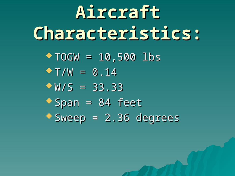
Aircraft Characteristics:Aircraft Characteristics:
TOGW = 10,500 lbsTOGW = 10,500 lbs T/W = 0.14T/W = 0.14 W/S = 33.33W/S = 33.33 Span = 84 feetSpan = 84 feet Sweep = 2.36 degreesSweep = 2.36 degrees
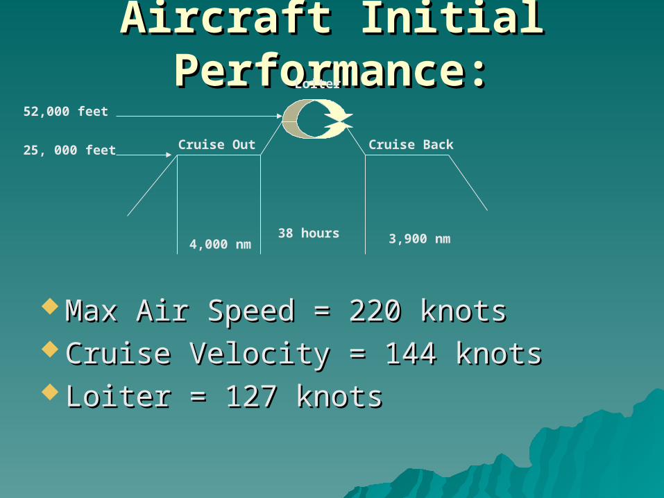
Aircraft Initial Performance:Aircraft Initial Performance:
Max Air Speed = 220 knotsMax Air Speed = 220 knots Cruise Velocity = 144 knotsCruise Velocity = 144 knots Loiter = 127 knotsLoiter = 127 knots
Cruise Out
4,000 nm
Loiter
38 hours
Cruise Back25, 000 feet
52,000 feet
3,900 nm
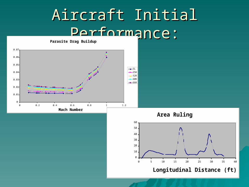
Aircraft Initial Performance:Aircraft Initial Performance:Parasite Drag Buildup
0
0.01
0.02
0.03
0.04
0.05
0.06
0.07
0 0.2 0.4 0.6 0.8 1 1.2
Mach Number
CDo
SL
25K
52K
60K
66K
Area Ruling
0
10
20
30
40
50
60
0 5 10 15 20 25 30 35 40
Longitudinal Distance (ft)
Cross Sectional Area (ft^2)

Methods of Altering Airfoil:Methods of Altering Airfoil:
Less power required to actively Less power required to actively change camberchange camber
CompactCompact Easy to InstallEasy to Install Alternative = Spar TwistingAlternative = Spar Twisting
Thunder-Piezoelectric Actuator

Airfoils: TipAirfoils: Tip
Tip Airfoil FX67-K-150/17
-0.5
-0.4
-0.3
-0.2
-0.1
0
0.1
0.2
0.3
0.4
0.5
0 0.2 0.4 0.6 0.8 1
Upper Surface Airfoil
Lower Surface Airfoil
Camber Line
Max Deflection 150/17 Airfoil
-0.5
-0.4
-0.3
-0.2
-0.1
0
0.1
0.2
0.3
0.4
0.5
0 0.2 0.4 0.6 0.8 1
Upper Surface
Lower Surface
Camber
Neg Deflection 150/17
-0.5
-0.4
-0.3
-0.2
-0.1
0
0.1
0.2
0.3
0.4
0.5
0 0.2 0.4 0.6 0.8 1
Upper Surface
Lower Surface
Camber
Original Airfoil Positively Deflected Airfoil
Negatively Deflected AirfoilMax thickness:
t/c = 0.15
Camber = 0.05
@40%chord
Max thickness:
t/c = 0.16
Camber = 0.06
@43%chord
Max thickness:
t/c = 0.14
Camber = 0.04
@34%chord
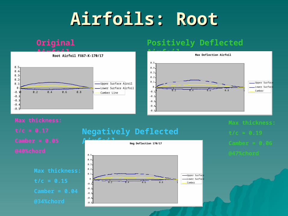
Airfoils: RootAirfoils: RootOriginal Airfoil Positively Deflected Airfoil
Negatively Deflected Airfoil
Root Airfoil FX67-K-170/17
-0.5
-0.4
-0.3
-0.2
-0.1
0
0.1
0.2
0.3
0.4
0.5
0 0.2 0.4 0.6 0.8 1
Upper Surface Airoil
Lower Surface Airfoil
Camber Line
Neg Deflection 170/17
-0.5
-0.4
-0.3
-0.2
-0.1
0
0.1
0.2
0.3
0.4
0.5
0 0.2 0.4 0.6 0.8 1
Upper Surface
Lower Surface
Camber
Max Deflection Airfoil
-0.5
-0.4
-0.3
-0.2
-0.1
0
0.1
0.2
0.3
0.4
0.5
0 0.2 0.4 0.6 0.8 1
Upper Surface
Lower Surface
Camber
Max thickness:
t/c = 0.17
Camber = 0.05
@40%chord
Max thickness:
t/c = 0.19
Camber = 0.06
@47%chord
Max thickness:
t/c = 0.15
Camber = 0.04
@34%chord
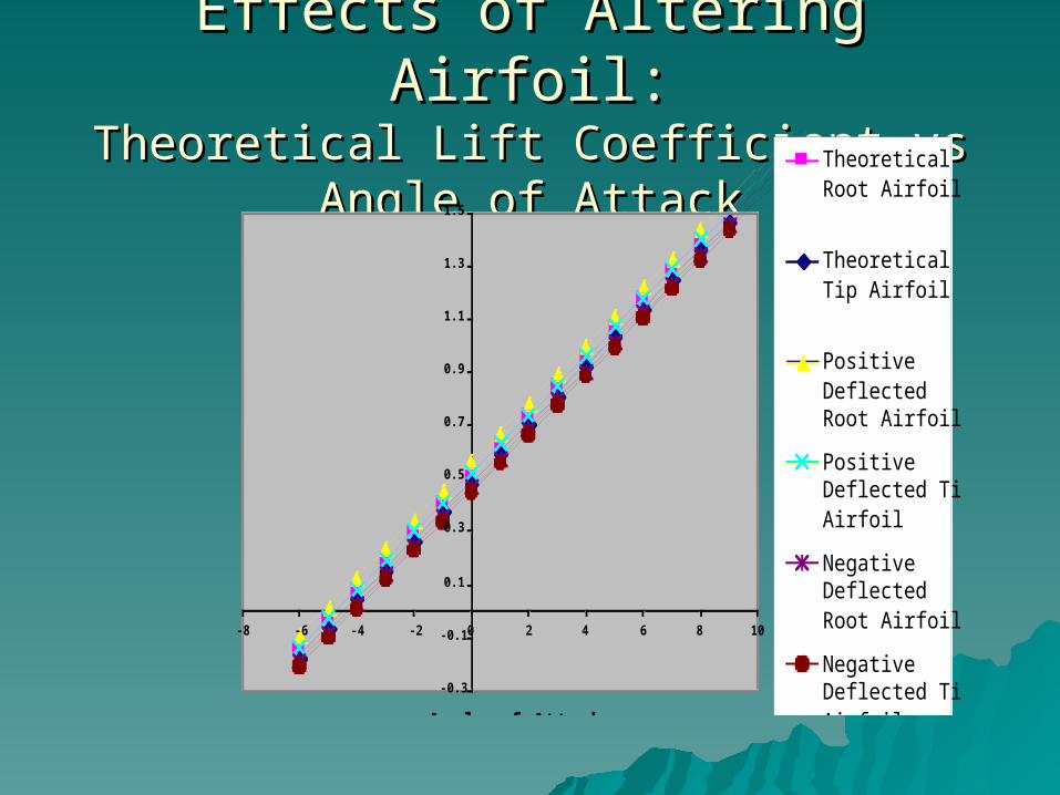
Effects of Altering Airfoil:Effects of Altering Airfoil:Theoretical Lift Coefficient vs Angle of Theoretical Lift Coefficient vs Angle of
AttackAttack
-0.3
-0.1
0.1
0.3
0.5
0.7
0.9
1.1
1.3
1.5
-8 -6 -4 -2 0 2 4 6 8 10
Angle of Attack
CL
Theoretical clRoot Airfoil
Theoretical clTip Airfoil
PositiveDeflectedRoot Airfoil
PositiveDeflected TipAirfoil
NegativeDeflectedRoot Airfoil
NegativeDeflected TipAirfoil

Effects of Altering Airfoils:Effects of Altering Airfoils:CD0 vs Mach NumberCD0 vs Mach Number
0
0.005
0.01
0.015
0.02
0.025
0.03
0.035
0.04
0.045
0.05
0 0.1 0.2 0.3 0.4 0.5 0.6 0.7 0.8 0.9 1
Mach Number
CDo Undeflected
Positive Deflection
Negative Deflection
0
0.005
0.01
0.015
0.02
0.025
0.03
0.035
0.04
0.045
0.05
0 0.1 0.2 0.3 0.4 0.5 0.6 0.7 0.8 0.9 1
Mach Number
CDo
Undeflected
PositiveDeflection
NegativeDeflection
At 25,000 feet At 52,000 feet
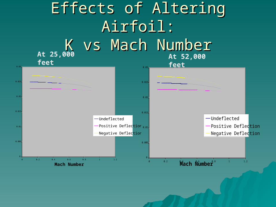
Effects of Altering Airfoil:Effects of Altering Airfoil:K vs Mach NumberK vs Mach Number
0
0.005
0.01
0.015
0.02
0.025
0.03
0 0.2 0.4 0.6 0.8 1 1.2
Mach Number
K Undeflected
Positive Deflection
Negative Deflection
0
0.005
0.01
0.015
0.02
0.025
0.03
0 0.2 0.4 0.6 0.8 1 1.2
Mach Number
KUndeflected
Positive Deflection
Negative Deflection
At 25,000 feet At 52,000 feet
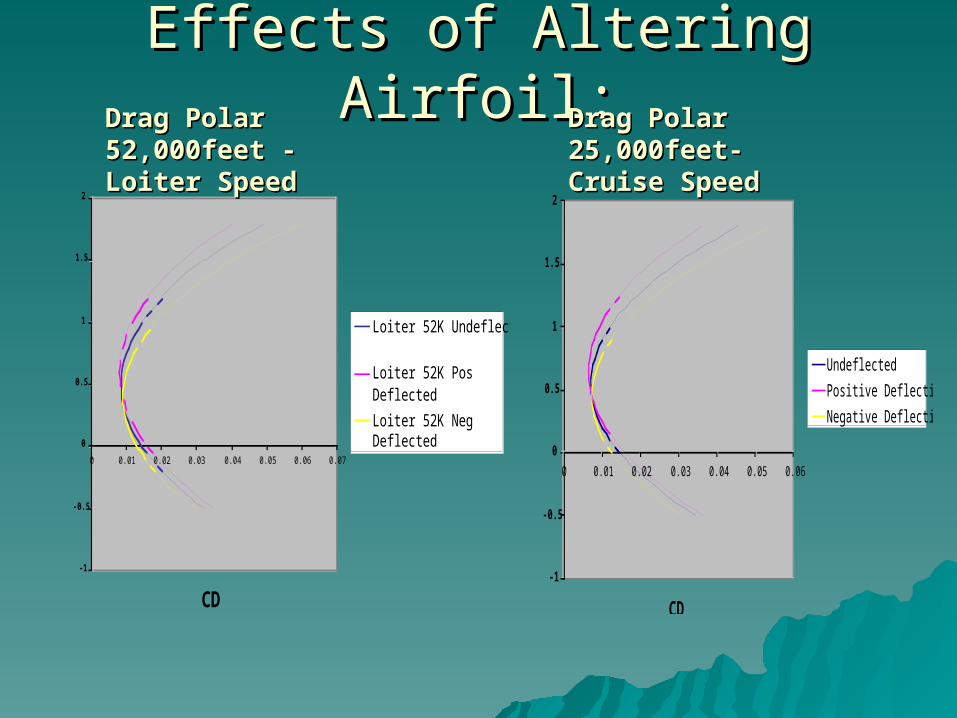
Effects of Altering Airfoil:Effects of Altering Airfoil:
-1
-0.5
0
0.5
1
1.5
2
0 0.01 0.02 0.03 0.04 0.05 0.06 0.07
CD
CL
Loiter 52K Undeflected
Loiter 52K PosDeflected
Loiter 52K NegDeflected
-1
-0.5
0
0.5
1
1.5
2
0 0.01 0.02 0.03 0.04 0.05 0.06
CD
CL
Undeflected
Positive Deflection
Negative Deflection
Drag Polar Drag Polar 52,000feet - 52,000feet - Loiter SpeedLoiter Speed
Drag Polar Drag Polar 25,000feet-25,000feet-Cruise SpeedCruise Speed

Effects of Altering Airfoils:Effects of Altering Airfoils:
0
10
20
30
40
50
60
70
80
0 0.1 0.2 0.3 0.4 0.5 0.6
CL
L/D
CL vs L/D
Pos Deflection
Neg Deflection
CL vs L/D at Cruise
0
10
20
30
40
50
60
70
80
90
0 0.1 0.2 0.3 0.4 0.5 0.6 0.7
CL
L/D
Undeflected
Positive Deflection
Negative Deflection
CL vs L/D at Loiter
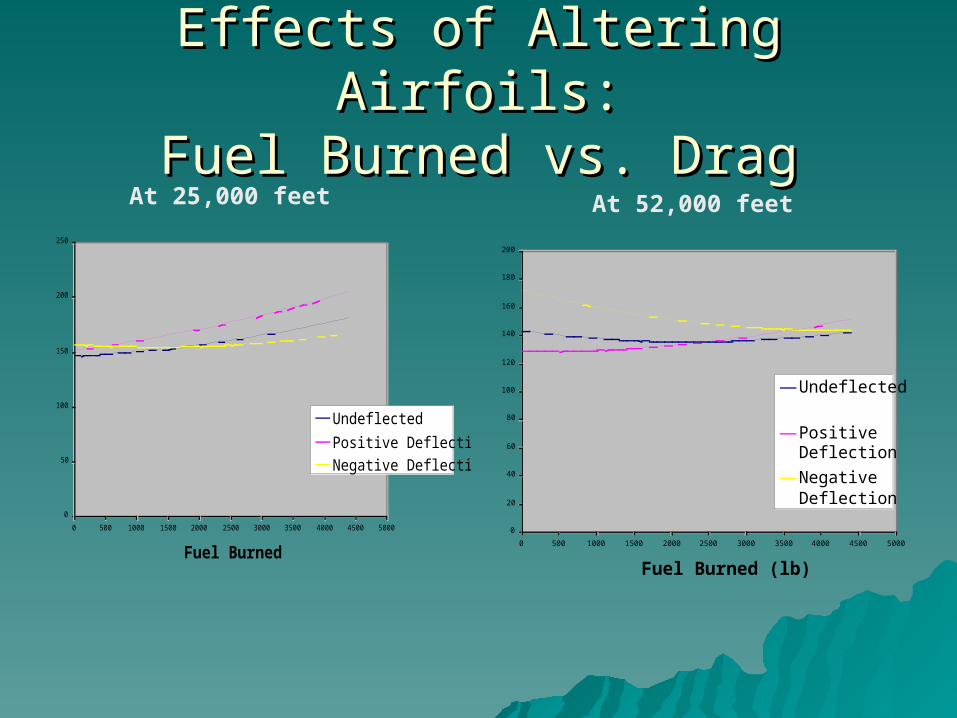
Effects of Altering Airfoils:Effects of Altering Airfoils:Fuel Burned vs. DragFuel Burned vs. Drag
0
50
100
150
200
250
0 500 1000 1500 2000 2500 3000 3500 4000 4500 5000
Fuel Burned
Drag (lb) Undeflected
Positive Deflection
Negative Deflection
0
20
40
60
80
100
120
140
160
180
200
0 500 1000 1500 2000 2500 3000 3500 4000 4500 5000
Fuel Burned (lb)
Drag (lb)
Undeflected
PositiveDeflection
NegativeDeflection
At 25,000 feet At 52,000 feet
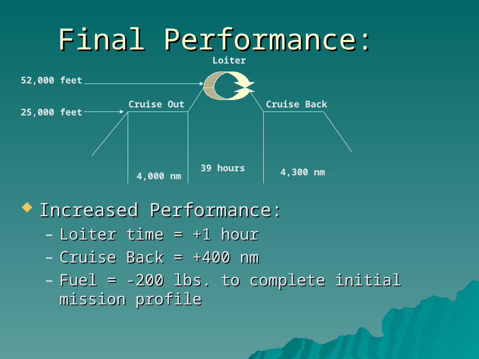
Final Performance:Final Performance:
Increased Performance:Increased Performance:– Loiter time = +1 hourLoiter time = +1 hour– Cruise Back = +400 nmCruise Back = +400 nm– Fuel = -200 lbs. to complete initial mission profileFuel = -200 lbs. to complete initial mission profile
Cruise Out
4,000 nm
Loiter
39 hours
Cruise Back
4,300 nm
25,000 feet
52,000 feet
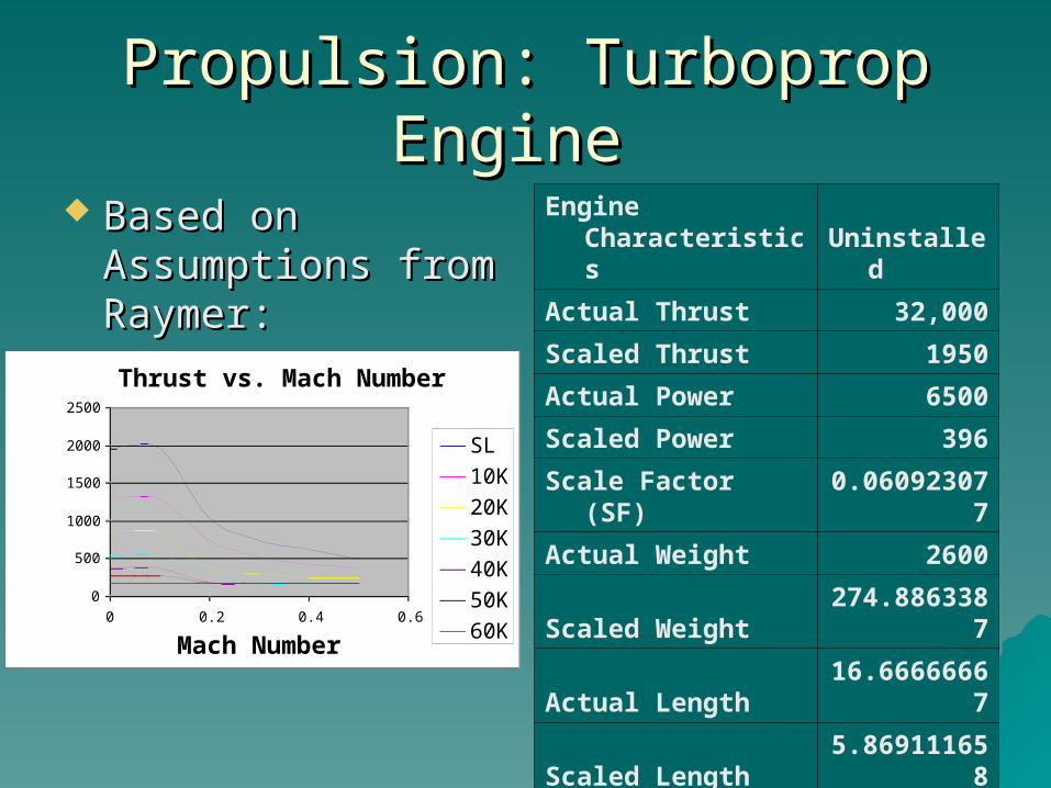
Propulsion: Turboprop Engine Propulsion: Turboprop Engine
Based on Based on Assumptions from Assumptions from Raymer:Raymer:
Engine Characteristics Uninstalled
Actual Thrust 32,000
Scaled Thrust 1950
Actual Power 6500
Scaled Power 396
Scale Factor (SF) 0.060923077
Actual Weight 2600
Scaled Weight 274.8863387
Actual Length 16.66666667
Scaled Length 5.869111658
Actual Diameter 3.833333333
Scaled Diameter 2.739999005
Thrust vs. Mach Number
0
500
1000
1500
2000
2500
0 0.2 0.4 0.6
Mach Number
Thrust (lb)
SL
10K
20K
30K
40K
50K
60K

Control ReversalControl Reversal
Increasing Roll Effectiveness Utilizing Wing Increasing Roll Effectiveness Utilizing Wing Twist due to Control Surface ReversalTwist due to Control Surface Reversal

Stability and ControlStability and Control
Control reversalControl reversal Roll effectivenessRoll effectiveness Lateral control governed by control Lateral control governed by control
systemsystem Control surface sizingControl surface sizing Aerodynamic center Aerodynamic center Divergence speedDivergence speed Flutter speedFlutter speed
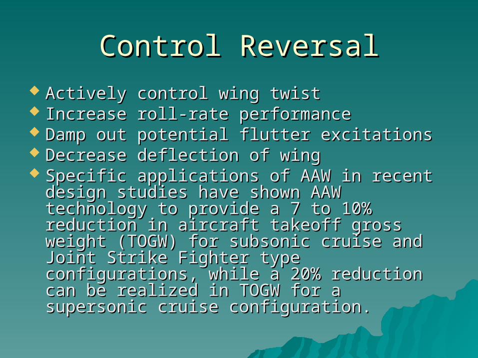
Control ReversalControl Reversal Actively control wing twist Actively control wing twist Increase roll-rate performanceIncrease roll-rate performance Damp out potential flutter excitationsDamp out potential flutter excitations Decrease deflection of wingDecrease deflection of wing Specific applications of AAW in recent Specific applications of AAW in recent
design studies have shown AAW design studies have shown AAW technology to provide a 7 to 10% technology to provide a 7 to 10% reduction in aircraft takeoff gross weight reduction in aircraft takeoff gross weight (TOGW) for subsonic cruise and Joint Strike (TOGW) for subsonic cruise and Joint Strike Fighter type configurations, while a 20% Fighter type configurations, while a 20% reduction can be realized in TOGW for a reduction can be realized in TOGW for a supersonic cruise configuration. supersonic cruise configuration.

Control Reversal:Control Reversal:
Negative Twist using Flaps and Ailerons
Positive Twist using Ailerons and Slats
Control Benefits/Issues of AAWControl Benefits/Issues of AAW If AAW works, then structural weight can be removed that If AAW works, then structural weight can be removed that
was otherwise needed to make the wing stiff. Also, the wing was otherwise needed to make the wing stiff. Also, the wing could have a higher aspect ratio, which would normally could have a higher aspect ratio, which would normally make it too flexible. Higher aspect ratio should reduce drag, make it too flexible. Higher aspect ratio should reduce drag, and combined with lower weight should improve payload-and combined with lower weight should improve payload-range performance. Boeing Sonic Cruiser officials have range performance. Boeing Sonic Cruiser officials have shown interest in the technique. shown interest in the technique.
The lurking concern is flutter. This is a reason the The lurking concern is flutter. This is a reason the preproduction F-18A design was chosen; its flight test preproduction F-18A design was chosen; its flight test showed that even though the wing was flexible, it did not showed that even though the wing was flexible, it did not have a flutter problem--hopefully removing this concern have a flutter problem--hopefully removing this concern from the AAW. There is no active flutter suppression in the from the AAW. There is no active flutter suppression in the planned AAW control laws. planned AAW control laws.

Roll PerformanceRoll Performance Less lateral moment of inertia of wing due to Less lateral moment of inertia of wing due to
lighter winglighter wing Twisting wings will allow better flow control over Twisting wings will allow better flow control over
wing surface thus generating more lift and wing surface thus generating more lift and reducing dragreducing drag
Creates a more efficient wing during Creates a more efficient wing during maneuveringmaneuvering
Decreases the parasitic drag caused by control Decreases the parasitic drag caused by control surfaces with rigid wingsurfaces with rigid wing
Uses traditional roll generation methods until Uses traditional roll generation methods until dynamic pressures are high enough to twist wing dynamic pressures are high enough to twist wing with control reversalwith control reversal
Above switch occurs in control law (future work)Above switch occurs in control law (future work)
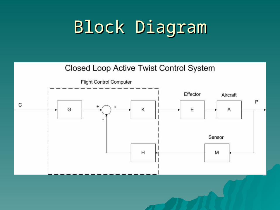
Block DiagramBlock Diagram

Control Surface SizingControl Surface Sizing Must generate enough Must generate enough
torque to twist the torque to twist the wing as desiredwing as desired
Control surfaces will Control surfaces will be used to damp out be used to damp out excitations that could excitations that could lead to flutterlead to flutter
Leading edge and Leading edge and trailing edge devices trailing edge devices used in main part of used in main part of wingwing
Trailing edge surface Trailing edge surface only on wingtiponly on wingtip

Aerodynamic CenterAerodynamic Center
Aerodynamic center is reference Aerodynamic center is reference point for pitching moment point for pitching moment calculationscalculations
Flight conditions are always subsonic Flight conditions are always subsonic for Marinerfor Mariner
Aerodynamic center can be assumed Aerodynamic center can be assumed to be located at quarter-chord of to be located at quarter-chord of Mean Aerodynamic Chord.Mean Aerodynamic Chord.

Divergence SpeedDivergence Speed Designed new wing to have the same divergence Designed new wing to have the same divergence
speed as current design. speed as current design. Sea levelSea level Safety factor = 1.25Safety factor = 1.25
Current divergence Current divergence speedspeed
426 feet per second426 feet per second
New divergence New divergence speedspeed
370 feet per second370 feet per second

Flutter SpeedFlutter Speed
New design flutter New design flutter speed at sea level:speed at sea level:
370 ft/sec370 ft/sec
Materials and StructuresMaterials and Structures
Material Selection Material Selection
Sources and estimates of limit loadsSources and estimates of limit loads
Structural conceptStructural concept
Wing shear and bending moment Wing shear and bending moment diagram approximations diagram approximations
Ixx, Iyy, J Ixx, Iyy, J

Material SelectionMaterial Selection
Similar materials as Similar materials as current designcurrent design
95% of aircraft is 95% of aircraft is compositescomposites
Composite properties Composite properties Utilize bend-twist Utilize bend-twist
coupling with layupcoupling with layup General dimensions of General dimensions of
current design current design conservedconserved

Finite Element ModelFinite Element Model
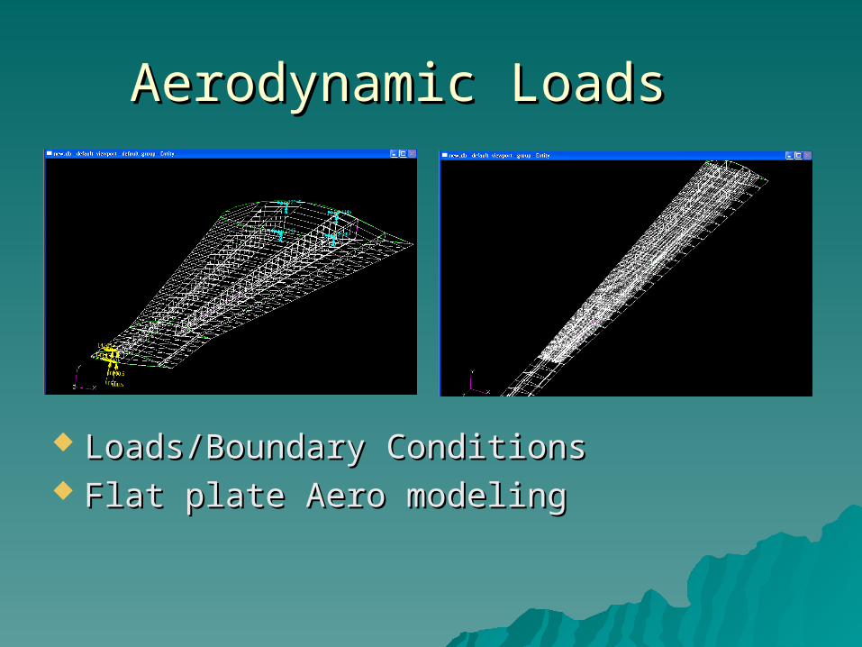
Aerodynamic LoadsAerodynamic Loads
Loads/Boundary ConditionsLoads/Boundary Conditions Flat plate Aero modelingFlat plate Aero modeling
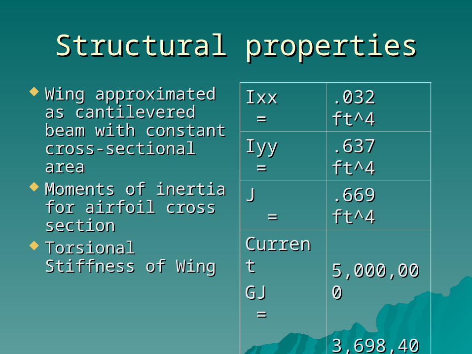
Structural propertiesStructural properties
Wing approximated Wing approximated as cantilevered as cantilevered beam with beam with constant cross-constant cross-sectional areasectional area
Moments of inertia Moments of inertia for airfoil cross for airfoil cross sectionsection
Torsional Stiffness Torsional Stiffness of Wingof Wing
Ixx =Ixx = .032 ft^4.032 ft^4
Iyy =Iyy = .637 ft^4.637 ft^4
J =J = .669 ft^4.669 ft^4
CurrentCurrent
GJ =GJ =
NewNew
GJ =GJ =
5,000,0005,000,000
3,698,4003,698,400

Limit LoadsLimit Loads
Maneuvering loadsManeuvering loads Gust loadsGust loads Control deflectionControl deflection Take-off and landing loadsTake-off and landing loads Power plant loadsPower plant loads Load factors approximately 3 to 4Load factors approximately 3 to 4
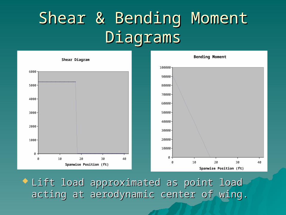
Shear & Bending Moment Shear & Bending Moment DiagramsDiagrams
Shear Diagram
0
1000
2000
3000
4000
5000
6000
0 10 20 30 40
Spanwise Position (ft)
Shear Load (lb)
Lift load approximated as point load acting Lift load approximated as point load acting at aerodynamic center of wing.at aerodynamic center of wing.
Bending Moment
0
10000
20000
30000
40000
50000
60000
70000
80000
90000
100000
0 10 20 30 40
Spanwise Position (ft)
Bending Moment (lb-ft)
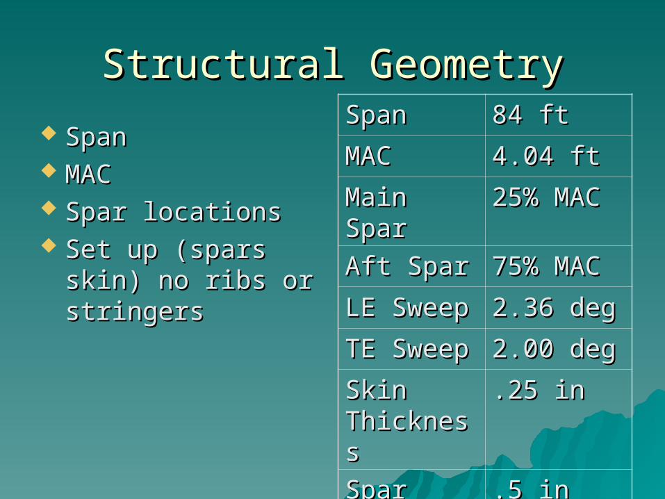
Structural GeometryStructural Geometry
SpanSpan MACMAC Spar locationsSpar locations Set up (spars skin) Set up (spars skin)
no ribs or stringersno ribs or stringers
SpanSpan 84 ft84 ft
MACMAC 4.04 ft4.04 ft
Main SparMain Spar 25% MAC25% MAC
Aft SparAft Spar 75% MAC75% MAC
LE SweepLE Sweep 2.36 deg2.36 deg
TE SweepTE Sweep 2.00 deg2.00 deg
Skin Skin ThicknessThickness
.25 in.25 in
Spar Spar ThicknessThickness
.5 in.5 in
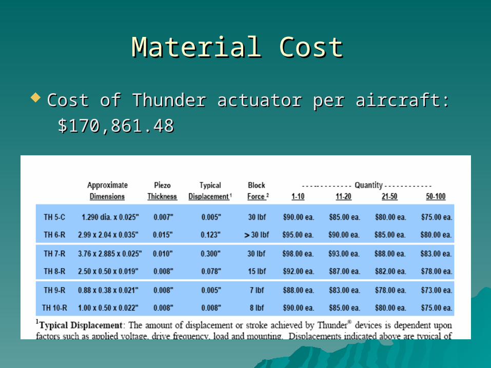
Material Cost Material Cost
Cost of Thunder actuator per aircraft:Cost of Thunder actuator per aircraft:
$170,861.48$170,861.48

DAPCA IV ModelDAPCA IV Model
Estimated Flyaway and RDT&E costs per Estimated Flyaway and RDT&E costs per aircraft for a 100 aircraft buy.aircraft for a 100 aircraft buy.
RDT&E + Flyaway=RDT&E + Flyaway= $637,505489.66$637,505489.66
Price per aircraft = Price per aircraft = $6,375,058.50$6,375,058.50
System Configuration System Configuration ImprovementsImprovements
Iterate to find optimal skin thicknessIterate to find optimal skin thickness Determine optimal spar dimensions Determine optimal spar dimensions
and locationsand locations More improvements can be made More improvements can be made
after test results are considered and after test results are considered and analyzedanalyzed

Cost ImprovementCost Improvement
Wait for the technology to matureWait for the technology to mature Make a special contract with supplier Make a special contract with supplier
to purchase Thunder actuators at a to purchase Thunder actuators at a lower costlower cost
Lower drag will increase efficiency Lower drag will increase efficiency and lower operational costsand lower operational costs
Conclusions:Conclusions:
Results: Not worth the extra cost for Results: Not worth the extra cost for MarinerMariner
Would be more profitable for a Would be more profitable for a Hunter/KillerHunter/Killer
Planes today do not operate at max Planes today do not operate at max efficiency – with increased efficiency – with increased technology this design will become technology this design will become the more profitable method to the more profitable method to increase performanceincrease performance

Future Work Needed:Future Work Needed:
Active Camber Change:Active Camber Change:– Research into Angle of Attack vs. Research into Angle of Attack vs.
Laminar FlowLaminar Flow Control Reversal:Control Reversal:
– Finite Element Model and AnalysisFinite Element Model and Analysis– Test article fabricationTest article fabrication– Flight TestingFlight Testing– Active flutter suppression in the planned Active flutter suppression in the planned
AAW control laws.AAW control laws.

References & References & Acknowledgements:Acknowledgements:
Josh Adams Josh Adams Dr. John KosmatkaDr. John Kosmatka John MeisnerJohn Meisner Raymer, Daniel P., “Aircraft Design: A Raymer, Daniel P., “Aircraft Design: A
Conceptual Approach”Conceptual Approach” Anderson, “Fundamentals of Anderson, “Fundamentals of
Aerodynamics”Aerodynamics” NASA PaperNASA Paper AIAA PaperAIAA Paper Beer, Ferdinand P., “Mechanics of Beer, Ferdinand P., “Mechanics of
Materials” Materials”