
UCS30 Manual 08-06-14 - University of...
53
S S S p p p e e e c c c t t t r r r u u u m m m T T T e e e c c c h h h n n n i i i q q q u u u e e e s s s U U U C C C S S S - - - 3 3 3 0 0 0 Universal Computer Spectrometer SPECTRUM TECHNIQUES, LLC. 106 Union Valley Road Oak Ridge, TN 37830 USA Telephone (865) 482-9937 Fax (865) 483-0473 e-mail: [email protected] Web Site: http://www.SpectrumTechniques.com/
Transcript of UCS30 Manual 08-06-14 - University of...

SSSpppeeeccctttrrruuummm TTTeeeccchhhnnniiiqqquuueeesss
UUUCCCSSS---333000
Universal Computer Spectrometer
SPECTRUM TECHNIQUES, LLC. 106 Union Valley Road Oak Ridge, TN 37830
USA
Telephone (865) 482-9937 Fax (865) 483-0473 e-mail: [email protected]
Web Site: http://www.SpectrumTechniques.com/
Spectrum Techniques UCS-30
2
Introduction ............................................................................................................................... 5 Screen View .................................................................................................................. 7
Installation................................................................................................................................. 7 Installing Software ........................................................................................................ 7 Uninstalling Software ................................................................................................... 8 Connections On Rear Panel .......................................................................................... 8
Analysis Modes ........................................................................................................................10 Pulse Height Analysis (PreAmp In) .............................................................................10 Pulse Height Analysis (Amp In) ..................................................................................10 Pulse Height Analysis (Direct In) ................................................................................10 Multi Channel Scaling (Internal) .................................................................................11 External Multi Channel Scaling ...................................................................................13 Mossbauer (Internal) ....................................................................................................14 Mossbauer (External) ...................................................................................................15
Operation..................................................................................................................................16 Live Mode ....................................................................................................................16 File Mode .....................................................................................................................16 Amp/HV/ADV .............................................................................................................16
Configuring System Parameters ..............................................................................................18 High Voltage ................................................................................................................18 Amplifier Coarse Gain .................................................................................................19 Amplifier Fine Gain .....................................................................................................19 ADC Conversion Gain .................................................................................................20 Lower and Upper Level Discriminators ......................................................................20 Voltage Polarity ...........................................................................................................21 Input Polarity ...............................................................................................................21 Peak Time Shaping ......................................................................................................22 Presets ..........................................................................................................................23
Preset Time ......................................................................................................23 Preset Integral ..................................................................................................24
Go, Stop and Erase .......................................................................................................24 Regions of Interest (ROI).............................................................................................24
Functions ..................................................................................................................................25 Energy Calibration .......................................................................................................25 Temperature Compensation .........................................................................................27 Isotope Matching .........................................................................................................28 Strip Background .........................................................................................................31
Load Spectrum .................................................................................................32 Load Background .............................................................................................32 Show Spectrum ................................................................................................32 Show Background ............................................................................................32 Overlay Spectra ................................................................................................33 Strip Background from Spectrum ....................................................................33
Data Smoothing ...........................................................................................................34 Menu Bar .................................................................................................................................34
File ...............................................................................................................................34

Spectrum Techniques UCS-30
3
File Open ..........................................................................................................35 File Save...........................................................................................................35 File Load Setup ................................................................................................35 File Save Setup ................................................................................................35 File Load Library .............................................................................................35 File Save Library..............................................................................................35 File Print...........................................................................................................35 File Print Preview ............................................................................................35 File Print Setup ................................................................................................36 File Exit ............................................................................................................36
Edit ...............................................................................................................................36 Edit Experiment ...............................................................................................36 Edit Iso Match ..................................................................................................36 Edit Smooth Data .............................................................................................38
Mode ............................................................................................................................38 Display .........................................................................................................................38
Display Peak Report ........................................................................................38 Display Data Report .........................................................................................39 Display Calibration ..........................................................................................39 Display ROIs ....................................................................................................39 Display Iso Match ............................................................................................39 Display Pixel Sizes ..........................................................................................39
Settings .........................................................................................................................40 Settings ROIs ...................................................................................................40 Settings Energy Calibrate ................................................................................41 Settings Preset ..................................................................................................42 Settings Amp/HV/ADC ...................................................................................42 Settings MCS ...................................................................................................42 Settings Color...................................................................................................43 Settings Confirm Spectrum Erasure .................................................................44 Settings Reset All Variables To Defaults ........................................................45
Strip Background .........................................................................................................45 Strip Background – Load Spectrum .................................................................46 Strip Background – Load Background ............................................................46 Strip Background – Show Spectrum ................................................................46 Strip Background – Show Background ............................................................46 Strip Background – Overlay Spectrum ............................................................47 Strip Background – Strip Background from Spectrum ....................................47
View .............................................................................................................................48 Tool Bar ...........................................................................................................48 Status Bar .........................................................................................................48
Help ..............................................................................................................................48 Contents ...........................................................................................................48 Using Help .......................................................................................................48 About................................................................................................................48
Tool Bar ...................................................................................................................................49
Spectrum Techniques UCS-30
4
Go .................................................................................................................................49 Stop ..............................................................................................................................49 Erase .............................................................................................................................50 Show Peak Report ........................................................................................................50 Show Data Report ........................................................................................................50 Amp/HV/ADC .............................................................................................................50 Presets ..........................................................................................................................50 ROI ...............................................................................................................................50 Spectrum Window Sizing ............................................................................................50
X axis expand ...................................................................................................51 X axis contract .................................................................................................51
Specifications ...........................................................................................................................52 Hardware ......................................................................................................................52 Software .......................................................................................................................53
Spectrum Techniques Contact .................................................................................................53

Spectrum Techniques UCS-30
5
Introduction
Hardware
The Universal Computer Spectrometer offers a unique solution for nuclear spectrometry using the PC platform. A 4K ADC (optional) combined with 8K of data memory and multi-channel scaling is ideally suited to scintillation spectroscopy and time related studies such as half-life decay.
Constructed in a sturdy, fully-shielded bench top enclosure with Universal Serial Bus (USB) computer interface, the multi-channel analyzer contains many advanced features including computer controlled amplifier and high voltage for PM tubes, upper- and lower-level discriminators, on-instrument data memory, and a comprehensive software package for use under Windows 2000 or higher.
The UCS-30 requires only an available USB port and is designed to work seamlessly with USB-equipped PCs. For stability and low noise operation, the unit is AC-line powered with an auto-sensing power supply for 100-250 VAC operation. An on-board microprocessor acts as the master controller and data storage device, as well as the communication link directly to the USB interface.
The integrated amplifier and high voltage are fully compatible with most standard scintillation detectors, eliminating the need for special tube bases and external modules. For ease of setup and calibration, coarse gain, fine gain, high voltage, and lower- and upper-level discriminator settings are controlled directly from the desktop computer. For operation with other types of detector systems such as alpha spectrometers or single photon counting, the scintillation preamp and amplifier can be bypassed (by computer control while in the “Mode” menu) which allows direct access to the ADC.
A 4096 channel ADC with de-randomizing buffer offers excellent data throughput at high counting rates with minimal dead-time losses. Conversion gain may be changed from 4096 to either 2048, 1024, 512, or 256 channels via the software. Data from the ADC is stored directly in on-board memory for autonomy and high-speed operation, freeing the host computer for other tasks.
Software
The UCS-30 produces a high-resolution, real-time live color display of spectral data with standard PC graphics running under Windows® (2000 and above). Operation is intuitive using pull-down menus and function buttons for the most commonly used commands and display options. The software offers full control of all features including preset live/real time and regions-of-interest, together with centroid, gross and net area calculations.
Control of the hardware amplifier, high voltage, ADC and input discriminators is also through function buttons for straightforward calibration and operation. To simplify identification of

Spectrum Techniques UCS-30
6
peaks, the cursor may be calibrated to read directly in energy units, using either a 2-point linear, or 3-point quadratic relationship calibration to allow for detector non-linearity.
Spectral files may be transferred to disk for long-term storage as binary files or transferred through the clipboard in ASCII format for exporting to other programs. Stored files may be used to collect background data over a long counting period that can be subtracted on a time proportional basis from the spectral data.
To aid in the identification of nuclides, the UCS-30 contains a unique peak-labeling feature named ISOMATCH. Providing the unit is accurately energy calibrated, the user may select a nuclide from the library and the corresponding characteristic emission lines are superimposed on the spectrum along with isotope and energy information. Using this feature, users may quickly check a spectrum and visually identify the emission components for each nuclide present. The ISOMATCH libraries may be created or customized using a text editor.
When operating in multi-channel scaling mode, the system may be calibrated in time units for direct readout from the cursor.
Both linear- and logarithmic-vertical display ranges are included, which can be useful when performing decay studies
Spectrum files can be transferred from the ICS 10 DOS program and the ICSW 16 Windows program to the UCS-30 Windows version format. Most functions may be accessed by more than one method. All the functions can be accessed from the Pull Down Menues, some from the Tool Bar Buttons, or by the mouse. If the function has a Tool Bar Button, its symbol will be shown on the left-hand side of the description.

Spectrum Techniques UCS-30
7
Screen View
Installation System Requirements The UCS-30 instrument uses a Universal Serial Bus (USB) to communicate with a PC. The PC must have USB compatible drivers, which are available standard on Windows 2000 and later releases. The performance of the USB on older systems may affect the perceived performance of the software; so we recommend that you use a Pentium III or greater class of microprocessor running at 550 MHz or greater to achieve desirable performance.
Installing Software Insert the included CD in your CD-ROM drive. The install program will automatically run. Follow the instructions to select the options you want to install. The default installation directory is C:\Program Files\Spectrum Techniques\UCS 30

Spectrum Techniques UCS-30
8
Example files:
Spectrum (*.spu) files: Normal.spu – contains an uncalibrated spectrum of CS-137. Calibrated.spu – contains a calibrated spectrum of CS-137.
Setup (*.sup) files:
Normal.sup – has settings used in Normal.spu. Calibrated.sup – has settings used in Calibrated.spu.
Library (*.itm) files
Isotopes.itm – contains a list of common isotope peaks for use with the IsoMatch function.
Uninstalling Software Go to the Windows Start Menu, select Settings, then Control Panel. On the Control Panel, select Add/Remove Software. Find UCS-30, double click and follow the instructions. Connections On Rear Panel
AC POWER IN
90 — 240 VAC
50 — 60HZ
USB
WARNING:
DANGEROUS VOLTAGES INSIDE SERVICE BY AUTHORIZED
PERSONNEL ONLY
MANUFACTURED BY SPECTRUM TECHNIQUES OAK RIDGE TENNESSEE 37830
MADE IN USA
HIGH VOLTAGE
INPUTMSBOUT
T/COMPMCS IN
GATE IN
ROIOUT
PREAMP POWER WARNING:
DANGEROUS VOLTAGESON HV CONNECTORS
POS NEG
Rear Panel

Spectrum Techniques UCS-30
9
CAUTION: Be sure to use the correct high voltage polarity for your device to prevent possible damage to equipment. POS HIGH VOLTAGE: MHV (or optional SHV) connector supplies positive 0 - 2048 volt @ 1mA maximum current to power scintillation detectors. High voltage is fully regulated and computer controlled in 2 volt increments. NEG HIGH VOLTAGE: Negative High Voltage is an Option. If this option is added, the UCS30 can also supply negative 0 - 2048 volt @ 1mA maximum current to power scintillation detector through an MHV (or optional SHV) connector. High voltage is fully regulated and computer controlled in 2 volt increments. Either the POS HIGH VOLTAGE or NEG HIGH VOLTAGE may be selected for use. Go to the “Settings” menu, then choose the “Amp/HV/ADC Settings” sub menu to gain access to the polarity selection. WARNING: HIGH VOLTAGE must be “OFF” before switching between POS HIGH VOLTAGE or NEG HIGH VOLTAGE. Failure to comply with this WARNING may result in severe instrument damage. INPUT: BNC connector. This input is for signals from a scintillation detector, scintillation preamplifier, or other type detector amplifiers (proportional counter, germanium detector) for eventual processing by the ADC. The internal scintillation preamplifier and also the scintillation amplifier can be bypassed using the “Mode” menu. MCS IN: BNC connector to input positive Multichannel Scaling (MCS) TTL pulses, > 150nsec. 5 MHz maximum rate. ROI OUT: (OPTIONAL) BNC connector supplies a pulse output when data is acquired in a channel marked as a Region of Interest (ROI). The pulse width is adjustable from 100 sec to 25 msec by an internal pot. The pulse amplitude is adjustable from 0 volt to 7.5 volts by an internal pot. GATE IN: BNC connector for connection to external coincidence unit. A positive TTL pulse causes the ADC to accept the next pulse. The Gate pulse must be present before the peak of the input Pulse. Gate pulse width = 50 nsec to 2 sec. MSB OUT: BNC connector to output the most significant MCS bit for Mossbauer Applications. The output pulse period in seconds is equal to the dwell time multiplied by the conversion gain. Used as a trigger for an external device (i.e. constant acceleration drive). Output will begin after the first pass in Mossbauer mode. T/COMP: Modular connector for connection to temperature compensated tube base. USB: Universal Serial Bus connector for communication with computer. PREAMP POWER: DB-9 connector, supplies 12v power for External preamplifier.

Spectrum Techniques UCS-30
10
(NOTE: An OPTIONAL 24v preamplifier power output is available to ensure compatiblity with germanium detectors.)
Analysis Modes Pulse Height Analysis (PreAmp In)
This is the normal operating mode for collecting sample gamma emission spectra. The amplitude of each detector pulse is measured by the ADC and stored as an amplitude (energy) spectrum. The X axis is scaled to the selected channels and the Y axis is scaled for the counts for each channel. Y axis counts that exceed the maximum Y axis value are ‘wrapped’; they no longer are scaled to the Y axis, and they appear in a different color.
Pulse Height Analysis (Amp In)
Similar to the 'PHA PreAmp In' operating mode except that the incoming signal bypasses the instrument's internal Pre-Amplifier. The amplitude of each detector pulse is measured by the ADC and stored as an amplitude (energy) spectrum. Pulse Height Analysis (Direct In)
Similar to the 'PHA PreAmp In' operating mode except that the incoming signal bypasses both the instrument's internal Pre-Amplifier and Amplifier. The amplitude of each detector pulse is measured by the ADC and stored as an amplitude (energy) spectrum.

Spectrum Techniques UCS-30
11
Multi Channel Scaling (Internal)
(UCS20 MCS Spectrum shown; UCS30 similar)
Multi Channel Scaling mode is used for measuring time related phenomena such as half-life decay or single photon counting. The ADC is bypassed and incoming events are routed directly into memory for specific predetermined times (dwell time) and stored in sequential memory locations. To use this mode, first acquire a spectrum using the Pulse Height Analysis mode. While acquiring the spectrum, adjust the LLD and the ULD to select the energy range of interest (for example, selecting only the 662 keV peak from CS-137 will eliminate unwanted background and produce a superior decay curve when using a Cs-137/Ba-137 mini-generator.) Click the Mode menu and select MCS

Spectrum Techniques UCS-30
12
Click the Settings menu and select MCS
The Setup MCS Dwell Time dialog box will appear:
Enter the Dwell Time. This time is for each memory location (channel). Remember the total pass time will be equal to (Conversion Gain x Dwell Time). Erase any current memory data and click START COUNTS. The UCS-30 will proceed to count incoming events for the selected dwell time, store the total in the first channel location, reset the counter and repeat the cycle storing each total count in sequential channels.

Spectrum Techniques UCS-30
13
External Multi Channel Scaling
If you wish to use an external pulse generation system such as a coincidence circuit, it will be necessary to bypass the on-board amplifier and discriminators. Connect the external counts connector to the Ext MCS connector on the back of the instrument and select the menu item MODE, then select External MCS. When operating in this mode, the MCS input requires positive TTL signals (>2.5v, >150 ns duration).

Spectrum Techniques UCS-30
14
Mossbauer (Internal)
This mode uses the internal preamp. Connect the signal into the INPUT BNC connector. The Mossbauer mode has variable dwell time ranging from 100 Sec to 6 Sec. A Preset number of passes can be set to the desired number or left at zero (0) for infinite passes. The following is the Mossbauer spectrum of a Co-57 source with an enriched Fe-57 absorber, showing nuclear Zeeman splitting.

Spectrum Techniques UCS-30
15
Mossbauer (External)
This mode requires the use of an external amplifier. The signal must connect to the MCS INPUT BNC connector. The Mossbauer External mode has variable dwell time ranging from 100 Sec to 6 Sec. A Preset number of passes can be set to the desired number or left at zero (0) for infinite passes. The following is the Mossbauer spectrum of a Co-57 source with an enriched Fe-57 absorber, showing nuclear Zeeman splitting.

Spectrum Techniques UCS-30
16
Operation
Live Mode
The software starts up in the Live Mode. This mode uses the USB to communicate with the instrument. If you access the File Menu and click on Open, a new window appears which looks like the current window, except that the title bar shows ‘File Mode’ instead of ‘Live Mode’. File mode does not communicate with the
instrument and is used only to view and manipulate files that have been saved to disk. File Mode
File Mode is accessible from the live mode by going to the File Menu and clicking on Open. Select the file you want to view. Some functions, which have no use when viewing files, are disabled in the Menus and the Toolbar.
Amp/HV/ADC Click the Amp/HV/ADC Button on the toolbar:
Or use the settings menu and click on Amp/HV/ADC

Spectrum Techniques UCS-30
17
The Amp/HV/ADC dialog box will appear.
Adjustments may be made to the amplification, high voltage, conversion gain, low level discriminator, and the high level discriminator. Selecting OK will cause these values to be written to the UCS-30 instrument.

Spectrum Techniques UCS-30
18
Configuring System Parameters: Once the program is running it will be necessary to configure the system parameters for correct operation and calibration. Place a gamma emitting check source near the detector face. Cesium-137 (Cs-137) is a good choice. It has a single peak at 662 keV. Click on Settings, then click on Amp/HV/ADC Set the high voltage to the voltage as listed by the detector manufacturer. As an example, set the high voltage to positive 600 volts; click ON. DO NOT exceed the maximum high voltage rating of the detector, usually 1200 volts. Set the amplifier COARSE GAIN to 8, and set the FINE GAIN to 1 as a starting position. Click on OK, to set adjustments and exit the menu. Start the data acquisition and adjust the amplifier gain until the 662 keV peak is approximately mid-scale. Once the acquisition is started, you may enter the Amp/HV/ADC menu and make adjustments while viewing the spectrum. This will allow you to position the peak in the desired channels.
High Voltage
High Voltage may be entered directly in the text box or may be scrolled to the value desired. A warning will be issued if you attempt to input a value higher than 1200 volts, since this is the highest value that many probes can tolerate without damage. If you know that your probe can accept higher than 1200 volts, you may increase the voltage up to 2048 volts.

Spectrum Techniques UCS-30
19
Amplifier Coarse Gain
Amplifier coarse gain may be set by clicking the radio-button next to the desired multiplier.
Amplifier Fine Gain
Amplifier fine gain may be directly entered as a multiplier value between 1.0 and 2.275 in 0.005 increments.

Spectrum Techniques UCS-30
20
ADC Conversion Gain
Conversion Gain represents the number of channels that will be sampled and displayed on the screen. Smaller values save as smaller files The conversion gain default setting is maximum channels. This is preferred for most scintillation detector applications and generally no adjustment is required. For certain applications, such as alpha spectroscopy, it may be necessary to change this parameter to either 256, 512, 1024, 2048 or 4096 channels.
Lower and Upper Level Discriminators
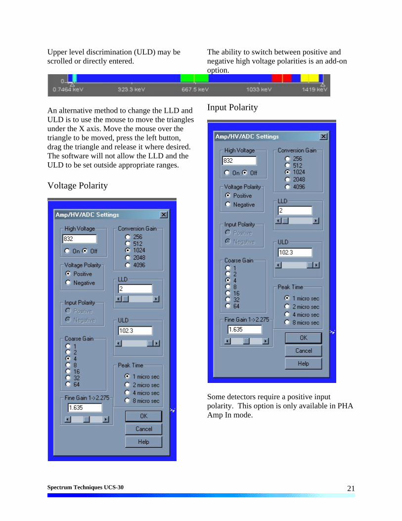
LLD and ULD, Lower Level Discriminator, and Upper Level Discriminator, allow the user to set a value between 0 and 102.3 (roughly percent) that cuts off the input signal before it gets to the ADC. The LLD is often used to block high-count signals (noise) in the low range that are not of interest, but require excessive time to sample. The ULD may be set up to 102.3. Low level discrimination (LLD) may be scrolled or directly entered.
Spectrum Techniques UCS-30
21
Upper level discrimination (ULD) may be scrolled or directly entered.
An alternative method to change the LLD and ULD is to use the mouse to move the triangles under the X axis. Move the mouse over the triangle to be moved, press the left button, drag the triangle and release it where desired. The software will not allow the LLD and the ULD to be set outside appropriate ranges. Voltage Polarity
The ability to switch between positive and negative high voltage polarities is an add-on option. Input Polarity
Some detectors require a positive input polarity. This option is only available in PHA Amp In mode.
Spectrum Techniques UCS-30
22
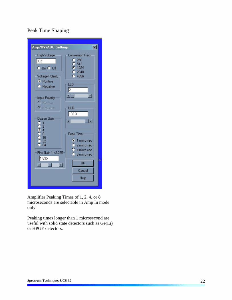
Peak Time Shaping
Amplifier Peaking Times of 1, 2, 4, or 8 microseconds are selectable in Amp In mode only. Peaking times longer than 1 microsecond are useful with solid state detectors such as Ge(Li) or HPGE detectors.
Spectrum Techniques UCS-30
23
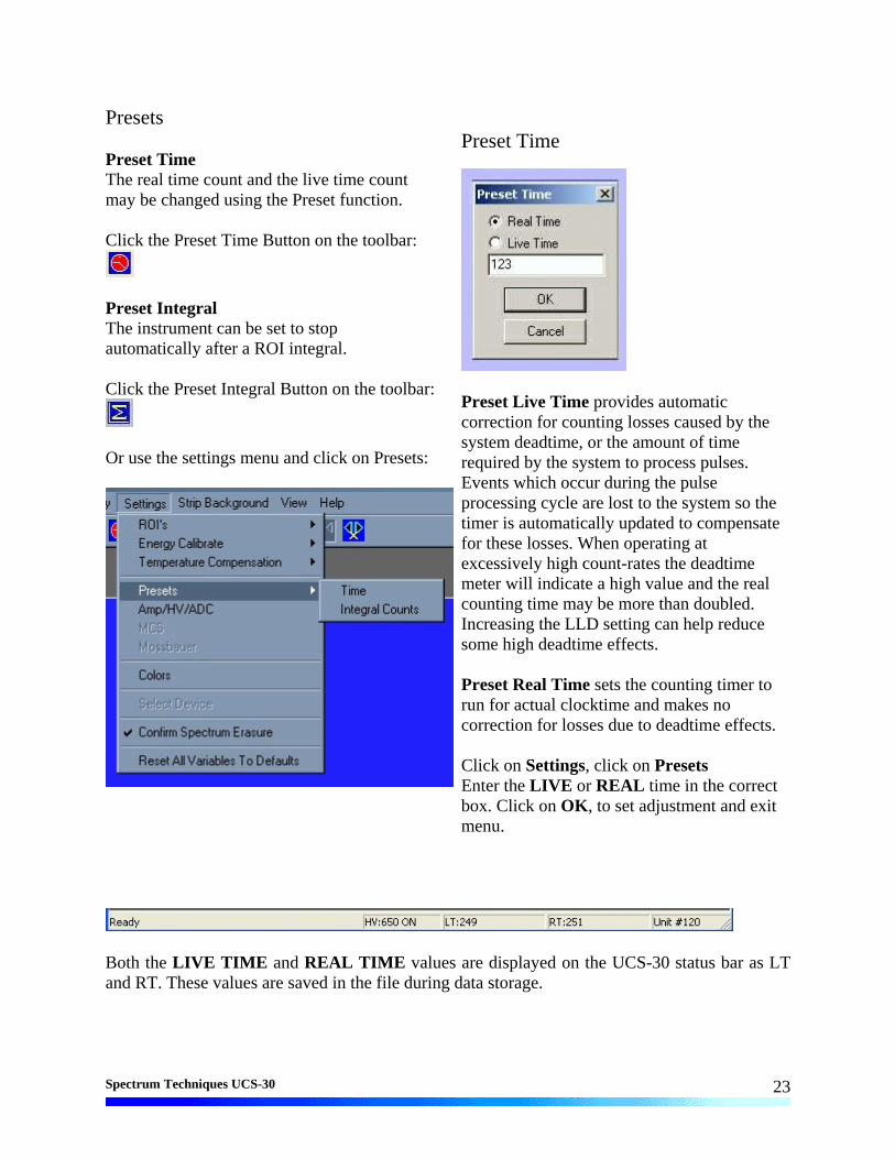
Presets Preset Time The real time count and the live time count may be changed using the Preset function. Click the Preset Time Button on the toolbar:
Preset Integral The instrument can be set to stop automatically after a ROI integral. Click the Preset Integral Button on the toolbar:
Or use the settings menu and click on Presets:
Preset Time
Preset Live Time provides automatic correction for counting losses caused by the system deadtime, or the amount of time required by the system to process pulses. Events which occur during the pulse processing cycle are lost to the system so the timer is automatically updated to compensate for these losses. When operating at excessively high count-rates the deadtime meter will indicate a high value and the real counting time may be more than doubled. Increasing the LLD setting can help reduce some high deadtime effects. Preset Real Time sets the counting timer to run for actual clocktime and makes no correction for losses due to deadtime effects. Click on Settings, click on Presets Enter the LIVE or REAL time in the correct box. Click on OK, to set adjustment and exit menu.
Both the LIVE TIME and REAL TIME values are displayed on the UCS-30 status bar as LT and RT. These values are saved in the file during data storage.

Spectrum Techniques UCS-30
24
Preset Integral
Set Integral To set an integral count it is necessary to first establish a ROI and then position the marker within the region. Selecting an ROI and setting a value other than 0 in preset integral will cause the system to STOP counting when the total counts of all the channels within the ROI reaches that value.
Go, Stop and Erase
Go, Stop and Erase functions are accessed with the Tool Bar buttons. Clicking on Start begins data collection. Clicking on Stop ends data collection. Clicking on Erase sets each channel’s data to zero. Additionally, three 'hot key' combination are defined as shortcuts for data acquisition functions. Pressing the appropriate action key while pressing the 'Ctrl' and 'Shift' keys will provide Go, Stop and Erase action. To Go press 'Ctrl+Shift+A'; to Stop press 'Ctrl+Shift+S'; and to Erase press 'Ctrl+Shift+E'.
Region of Interest (ROI)
Region of interest (ROI) selection is an advanced feature which provides instantaneous computation of peak gross and net counts. These values may be used along with isotope decay tables and detection efficiency to calculate absolute or relative isotopic activities. ROIs must not overlap and need to be separated by at least one channel for correct area calculation. Up to 16 different ROIs are possible using the color selector from the pull down Settings menu.

Spectrum Techniques UCS-30
25
Set ROI To set an ROI around a peak, click the ROI button on the Tool Bar. Click the left mouse button at the beginning of the ROI, hold down the left mouse button and drag the marker to the other side of the peak, release mouse button. Clear ROI Move marker to the ROI to be cleared. Open the Setting Menu, open ROI and select Clear ROI. Gross and Net Count When the marker is positioned in a region of interest (ROI), the UCS-30 software automatically calculates the Gross and Net
area of the region. In order to minimize statistical effects at the ROI endpoints, a 3-point averaging technique is applied. The contents of channels (n-1), (n), and (n+1) are summed and averaged to derive the content of the endpoint channel for the net area computation. A linear interpolation is performed between these averaged endpoint values and counts below this interpolation are subtracted to arrive at the Net area of the peak. Gross counts is the sum of all channels in the ROI. Position the marker in the peak of interest. The Gross and Net areas are automatically computed and displayed on the spectrum screen.
Functions
Energy Calibration
The energy calibration feature allows the marker to read directly in energy units. Two calibration functions are possible, a 2-point linear, or a 3-point quadratic fit.
In order to perform an energy calibration, it is first necessary to acquire a spectrum using known isotopes. Cs-137 together with Co-60 works well for many applications, producing gamma lines at 32 keV, 662 keV, 1173 keV and 1332 keV. Select 2-point or 3-point mode and enter the calibration units to be used, (keV or MeV). Position the marker at the highest channel of the first peak and enter the peak energy value. Move the marker to the high point on the second peak to be used for the calibration, enter energy number. If a 3-point calibration is required, continue by moving the marker to the peak channel of the third peak, enter its energy and click OK. The system will now be calibrated and the marker position will read directly in energy. To return to the channel number mode, click on Settings, click on Uncalibrate.

Spectrum Techniques UCS-30
26
Energy Calibration may also be selected using the right mouse button.
Auto Calibrate is a convenience provided for users working in the under 1000 keV energy range. Selecting Auto Calibrate will initiate an acquisition sequence that attempts to determine optimum detector voltage and gain settings for a calibrated energy spectrum display. This calibration is specifically designed to place the primary peak of a Cesium-137 source at a point approximately 65% of the x-axis scale. Once located, the energy calibration coefficients are calculated to provide a two point calibration (32 and 662 keV. Use of other sources will result in erroneous calibration.
The calibration sequence can require a few minutes to complete. In the absence of an adequate source or improper cable connection, the process may not succeed. Once Auto Calibrate begins, an
information dialog box is displayed which advises to wait for completion and provides an opportunity to cancel the calibration. Pressing of the Cancel button will result in the auto-calibration process being aborted and the high voltage setting being reset to zero. If allowed to work to completion, the gains and voltage will be left at the determined calibration settings and the spectrum scale will be displayed in energy.

Spectrum Techniques UCS-30
27
Temperature Compensation
---THIS FUNCTION IS NOT CURRENTLY AVAILABLE --- The temperature compensation feature allows the UCS 30 to automatically adjust the fine high voltage to correct for temperature variation. In order to perform temperature compensation, the fine high voltage factor (measured in channels/step) and temperature coefficient (measured in channels / degree celsius) most be known. These can be provided by the use in the Parameters menu, or found by allowing the UCS-30 to calibrate for temperature compensation using a cesium source.
Setup
The setup menu provides the UCS 30 with the length of time it should monitor temperature variations to calculate the temperature coefficient. The interval, which must be set to 5~60 minutes, is how often the UCS 30 measures the temperature and cesium peak. The time, which must be set to 4~24 hours, is how long the UCS 30 will stay in calibration mode. Parameters
The fine high voltage factor (measured in channels/step) and temperature coefficient (measured in channels / degree celsius) can be entered in the parameters menu. Also, temperature compensation may be enabled in this dialog box by clicking the enable checkbox. The parameters are automatically changed and temperature compensation is enabled after calibrating for temperature compensation.

Spectrum Techniques UCS-30
28
Selecting calibrate will initiate an acquisition sequence that attempts to determine the compensation parameters. First it attempts to AutoCalibrate the system. Once energy calibrated, the UCS 30 will attempt to find the temperature compensation parameters by finding the cesium peak at the specified interval over the specified time.
Since the calibration will take several hours, an information dialog box is displayed which advises to wait for completion and provides an opportunity to cancel the calibration. Pressing of the Cancel button will result in the temperature compensation calibration process being aborted.
Isotope Matching

Spectrum Techniques UCS-30
29
Displaying Isotope Peaks Isotope peaks may be indicated on calibrated spectra. These peaks are selected from a list provided by selecting the Display menu and clicking on Iso Match. The following dialog box will be displayed:
Click the isotopes peaks in the window that you want to display. These will be highlighted to indicate selection. When your list is complete, click Okay to display them. Editing the Iso Match list Select the Edit menu and click Iso Match. The following dialog box will be displayed:

Spectrum Techniques UCS-30
30
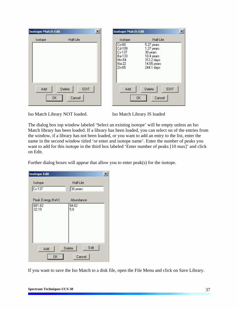
IsoMatch Library NOT loaded. IsoMatch Library IS loaded The dialog box top window labeled ‘Select an existing isotope’ will be empty unless an Iso Match library has been loaded. If a library has been loaded, you can select on of the entries from the window, if a library has not been loaded, or you want to add an entry to the list, enter the name in the second window titled ‘or enter and isotope name’. Enter the number of peaks you want to add for this isotope in the third box labeled ‘Enter number of peaks [10 max]’ and click on Edit. Further dialog boxes will appear that allow you to enter peak(s) for the isotope.
If you want to save the Iso Match to a disk file, open the File Menu and click on Save Library.

Spectrum Techniques UCS-30
31
Strip Background
Allows the user to load a spectrum and a background and then strip the background from the spectrum. Strip Background
The Strip Background option is available only in the File Mode. The user may load two files (Spectrum and Background) and subtract the second file from the first. The portion subtracted is based on a time adjustment to the data in the second file. For example if the first file was measured with 100 seconds live time and the second file was measured with 200 seconds live time, then the data in the second file is divided by 2 (200 seconds / 100 seconds) before it is subtracted. Background Subtraction This is a special case of spectrum stripping. Collect a background sample spectrum, usually for a long collection time. Load this spectrum as Background and click on ‘Strip Background from Spectrum.’ The live time fraction of the background is subtracted from spectrum. This provides a convenient method of removing naturally occurring background from a sample spectrum and can be very useful when working with low level environmental samples.

Spectrum Techniques UCS-30
32
Load Spectrum
Click on Load Spectrum and in the File Dialog Box that opens, select the spectrum you intend to have the background stripped from. For example, the spectrum may be taken for an isotope; the background may be the readings with no isotope present. Load Background
Click on Load background and in the File Dialog Box that opens, select the background you intend to strip from the first. For example,
the spectrum may be taken for an isotope; the background may be readings with no isotope present. Show Spectrum
Click Show Spectrum to view spectrum. Show Background
Click Show Background to view background.

Spectrum Techniques UCS-30
33
Overlay Spectra Click Overlay Spectra to view the spectrum and the background at the same time.
Strip Background from Spectrum
Click Strip Background from Spectrum to subtract the two spectra, where the background is corrected for the difference in the data collection time to give a correct proportion. As an example, if the background count time is 10 minutes and the sample count time is 60 minutes, then the Strip Background from Spectrum function will subtract 1/6 (10 minutes background count time/60 minutes sample count time) of the background counts from the sample spectrum.

Spectrum Techniques UCS-30
34
Data Smoothing
Click Smooth Data to perform a 3-point averaging of the data currently being displayed. The function uses the following algorithm to average data in each channel, where ‘n’ is the channel number.
(n-1)+(n)+(n+1) . 3
Menu Bar Many advanced functions are possible via the pulldown menus. This section describes each operation in the sequence they appear. Black letters indicate the function is operational, gray indicates not-operational, highlighted indicates the function to be activated.
File

Spectrum Techniques UCS-30
35
File Open File Open allows the user to open data files. A new instance of the UCS-30 application in the File Mode is generated. File Save The spectrum data and the associated setup and experiment data are saved to a *.spu file. File Load Setup Used if power has been turned off to the USC30, Load Setup loads a previously saved setup file and quickly restores the analyzer to its previous operating condition.
High Voltage must be turned on after loading setup ! File Save Setup Once the UCS-30 has been setup and calibrated, Save Setup stores all operating parameters as a disk file for subsequent retrieval. See Load Setup description, above, for this procedure to restore the UCS30 to a previous condition.
File Load Library Allows loading of an Iso Match library file (*.itm). File Save Library Allows saving of an Iso Match library file (*.itm). File Print Allows the user to print the displayed spectrum. File Print Preview Allows the user to preview the spectrum as it will be printed. File Print Setup Allows the user to adjust the printer parameters before printing. File Exit

Spectrum Techniques UCS-30
36
Closes the application. Edit
Edit Experiment
Edit Experiment provides a means of inserting text into spectral file headers for referencing specific measurements. This text is saved along with data and parameter information in .SPE and .TSV files, and it is used for the Peak Report and the Data Report. The comments field saves a maximum of 50 characters. Enter the desired text into the dialog box and click OK when finished. Edit Iso Match Editing the Iso Match list Select the Edit menu and click Iso Match. The following dialog box will be displayed:
Spectrum Techniques UCS-30
37
Iso Match Library NOT loaded. Iso Match Library IS loaded The dialog box top window labeled ‘Select an existing isotope’ will be empty unless an Iso Match library has been loaded. If a library has been loaded, you can select on of the entries from the window, if a library has not been loaded, or you want to add an entry to the list, enter the name in the second window titled ‘or enter and isotope name’. Enter the number of peaks you want to add for this isotope in the third box labeled ‘Enter number of peaks [10 max]’ and click on Edit. Further dialog boxes will appear that allow you to enter peak(s) for the isotope.
If you want to save the Iso Match to a disk file, open the File Menu and click on Save Library.

Spectrum Techniques UCS-30
38
Edit Smooth Data Edit Smooth Data allows the user to apply a three-point smoothing algorithm to the displayed data. Mode
Display
Display Peak Report If regions of interest have been set around peaks in a spectrum, the Peak Report provides a convenient method of displaying peak information in tabular form. Readout will be in energy units if the energy calibration is active. Display Data Report The Data Report includes all hardware setting, counting parameters and spectrum data. ROI data is reported by lower and upper channels set, gross, net, FWHM, centroid, all channels and corresponding counts. Display Calibration Display Calibration allows the user to switch between on/off in calibration mode and channel numbers or energy is displayed on the horizontal line. Display ROIs Display ROIs lets the user toggle between displaying and not displaying the ROIs. Display Iso Match Display Iso Match lets the user toggle between displaying and not displaying the Iso Match peaks.
Spectrum Techniques UCS-30
39
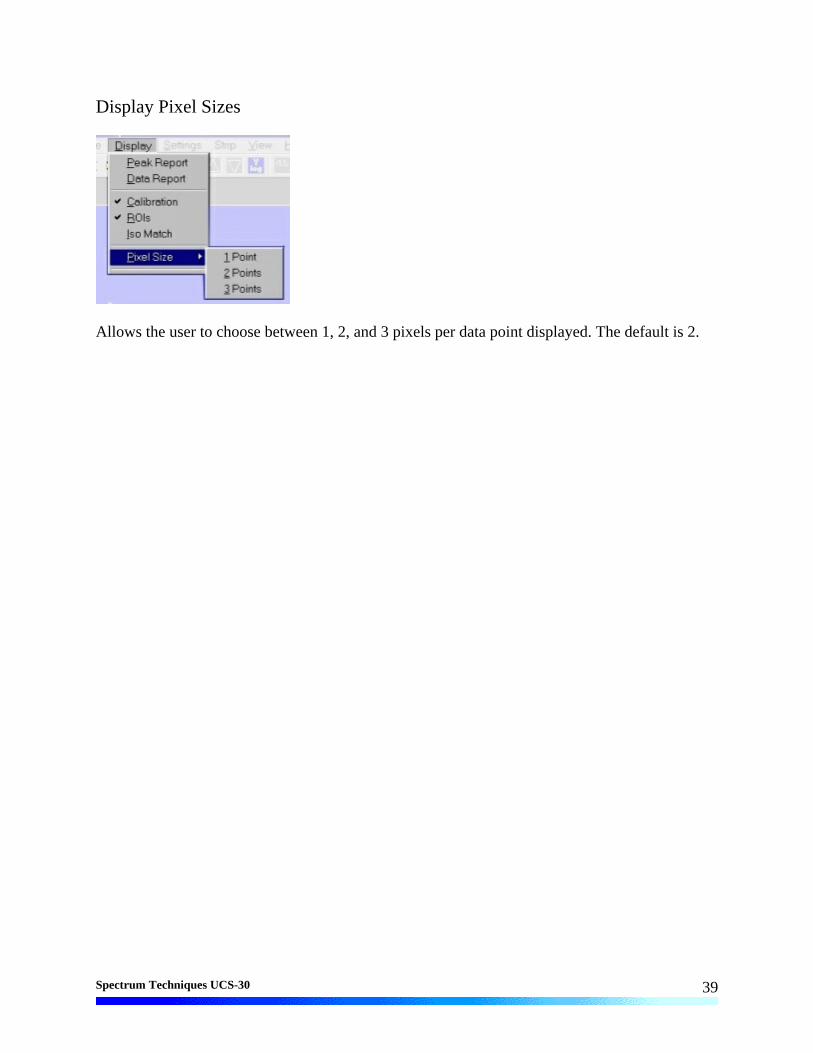
Display Pixel Sizes
Allows the user to choose between 1, 2, and 3 pixels per data point displayed. The default is 2.

Spectrum Techniques UCS-30
40
Settings
Settings ROIs
Allows the user to select the option to set or clear an ROI.
Clear ROI
Clicking on Clear ROI will clear the ROI indicated by the marker.
Clicking on Set ROI allows the user to set the ROI.
Spectrum Techniques UCS-30
41
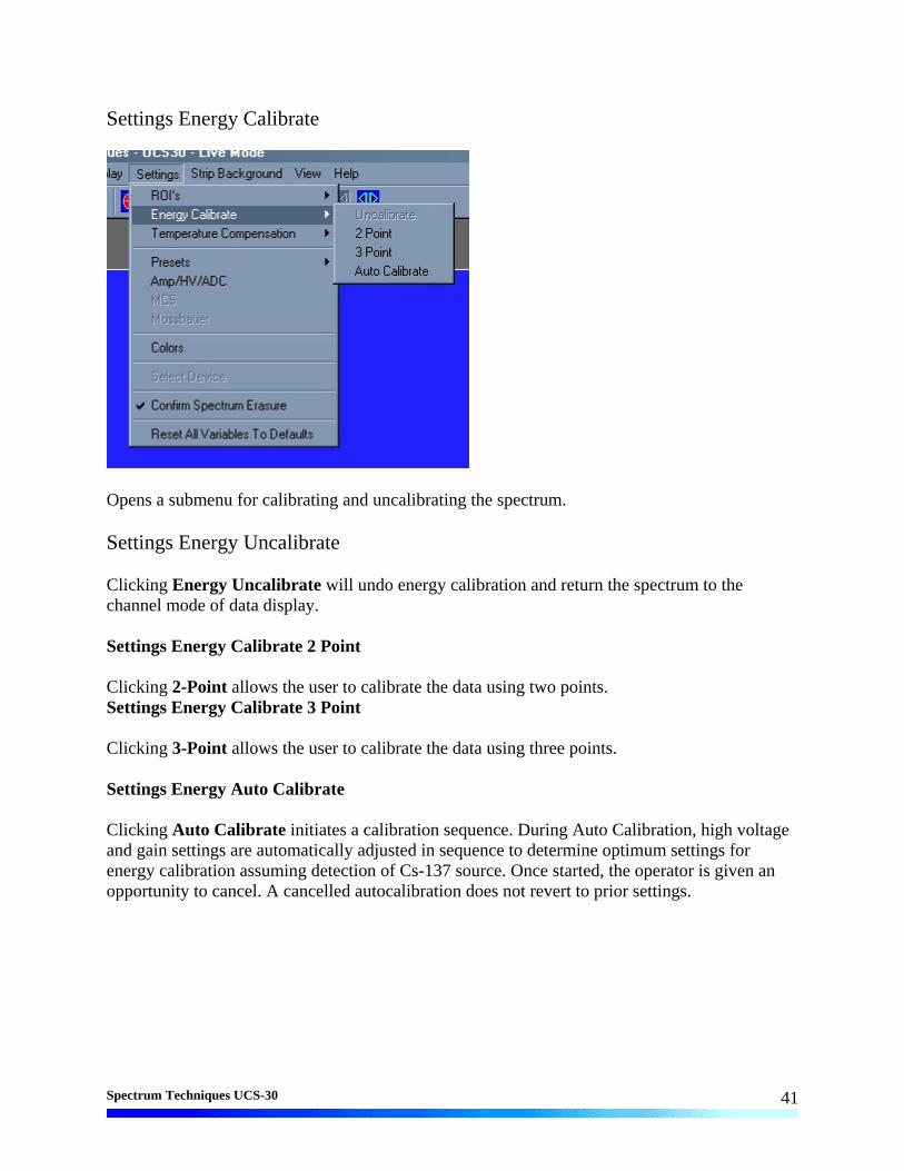
Settings Energy Calibrate
Opens a submenu for calibrating and uncalibrating the spectrum. Settings Energy Uncalibrate Clicking Energy Uncalibrate will undo energy calibration and return the spectrum to the channel mode of data display. Settings Energy Calibrate 2 Point Clicking 2-Point allows the user to calibrate the data using two points. Settings Energy Calibrate 3 Point Clicking 3-Point allows the user to calibrate the data using three points. Settings Energy Auto Calibrate Clicking Auto Calibrate initiates a calibration sequence. During Auto Calibration, high voltage and gain settings are automatically adjusted in sequence to determine optimum settings for energy calibration assuming detection of Cs-137 source. Once started, the operator is given an opportunity to cancel. A cancelled autocalibration does not revert to prior settings.

Spectrum Techniques UCS-30
42
Settings Preset Clicking Presets allows the user to select the Presets Dialog box. Settings Amp/HV/ADC Clicking Amp/HV/ADC allows the user to select the Amp/HV/ADC Dialog box. Settings MCS Clicking MCS allows the user to access the MCS Dwell Time dialog box, if the Mode is set to MCS.
Scroll to the desired Dwell Time then highlight the value selected then press OK.

Spectrum Techniques UCS-30
43
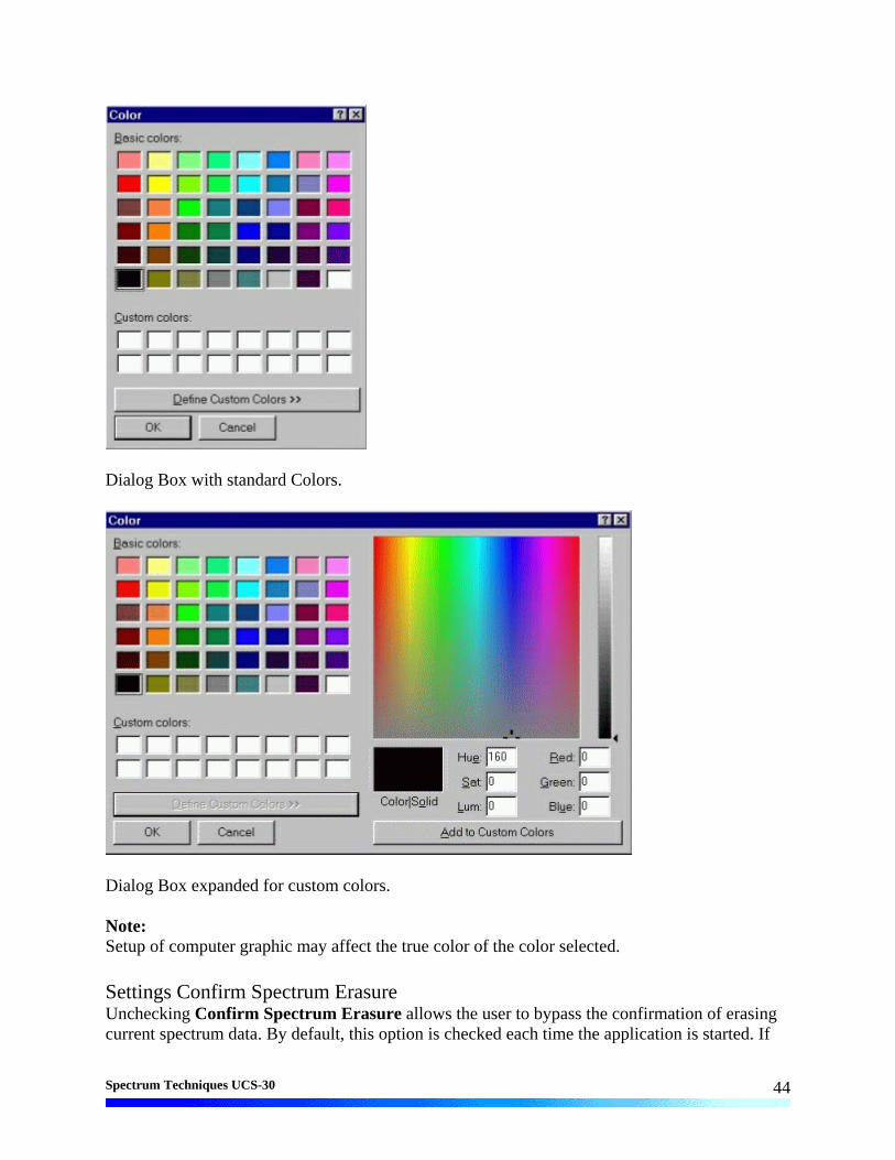
Settings Color Clicking Color allows the user to select the Colors Dialog Box to set or change the colors for the ROIs and Background .
The Color Dialog Box allows the user to select custom colors for ROIs, Plot Background, Plot Border and Text. Select the item to change, click on Change, select the desire color, click on OK, returns to the Color screen, make additional color changes, when all color changes have been made, click on OK, enters data and returns to spectrum screen. Color allows the user to select a range of Basic Colors or create Custom Colors.
Spectrum Techniques UCS-30
44
Dialog Box with standard Colors.
Dialog Box expanded for custom colors. Note: Setup of computer graphic may affect the true color of the color selected. Settings Confirm Spectrum Erasure Unchecking Confirm Spectrum Erasure allows the user to bypass the confirmation of erasing current spectrum data. By default, this option is checked each time the application is started. If

Spectrum Techniques UCS-30
45
the setting is unchecked, erasure of the current spectrum is immediate and cannot be undone--use this feature wisely. When the setting is checked, a request to erase is followed by the display of a confirmation dialog box to give an opportunity to cancel the request. Settings Reset All Variables To Defaults Clicking Reset All Variables To Defaults results in configuration settings being reset to the initialized state.
A confirmation dialog box will be presented to give an opportunity to cancel the request. Once accepted, the changes are made and cannot be undone. Click on 'Yes' to reset defaults, or on 'No' to cancel the operation. Strip Background
Allows the user to load a spectrum and a background and then strip the background from the spectrum. Strip Background

Spectrum Techniques UCS-30
46
The Strip Background option is available only in the File Mode. The user may load two files (Spectrum and Background) and subtract the second file from the first. The portion subtracted is based on a time adjustment to the data in the second file. For example if the first file was measured with 100 seconds live time and the second file was measured with 200 seconds live time, then the data in the second file is divided by 2 (200 seconds / 100 seconds) before it is subtracted. Background Subtraction This is a special case of spectrum stripping. Collect a background sample spectrum, usually for a long collection time. Load this spectrum as Background and click on ‘Strip Background from Spectrum.’ The live time fraction of the background is subtracted from spectrum. This provides a convenient method of removing naturally occurring background from a sample spectrum and can be very useful when working with low level environmental samples. Load Spectrum
Click on Load Spectrum and in the File Dialog Box that opens, select the spectrum you intend to have the background stripped from. For example, the spectrum may be taken for an isotope, the background may be the readings with no isotope present.
Load Background
Click on Load background and in the File Dialog Box that opens, select the background you intend to strip from the first. For example, the spectrum may be taken for an isotope, the background may be readings with no isotope present. Show Spectrum
Click Show Spectrum to view spectrum. Show Background
Click Show Background to view background.

Spectrum Techniques UCS-30
47
Overlay Spectra
Click Overlay Spectra to view the spectrum and the background at the same time. Strip Background from Spectrum
Click Strip Background from Spectrum to subtract the two spectra, where the background is corrected for the difference in the data collection time to give a correct proportion. As an example, if the background count time is 10 minutes and the sample count time is 60 minutes, then the Strip Background from Spectrum function will subtract 1/6 (10 minutes background count time/60 minutes sample count time) of the background counts from the sample spectrum.

Spectrum Techniques UCS-30
48
View
Allows the user to display or not display the Tool Bar and/or the Status Bar. Tool Bar Allows the user to display or not display the Tool Bar. Status Bar
Allows the user to display or not display the Status Bar. Help
The Help menu provides a convenient operator reference for the UCS-30 in the standard Windows Help format. Contents The Help menu provides a convenient operator reference for the UCS-30 in the standard Windows Help format. Using Help
The Using Help item provides the standard Windows Help on using the Windows Help system.

Spectrum Techniques UCS-30
49
About Displays a splash screen with the Application name and version number.
Tool Bar
Go
Go allows the user to start the acquire mode of a spectrum. This can also be accomplished by clicking on the green Start Icon on the display screen. Optionally, pressing 'A' while pressing and holding 'Ctrl' and 'Shift' keys will start acquisition.
Stop
Stop allows the user to stop the acquire mode of a spectrum. This can also be accomplished by clicking on the red Stop Icon on the display. Optionally, pressing 'S' while pressing and holding the 'Ctrl' and 'Shift' keys will stop acquisition.

Spectrum Techniques UCS-30
50
Erase
Erase allows the user to erase the spectrum when in stop mode. This can also be accomplished by clicking on the Eraser Icon on the display screen. Optionally, pressing 'E' while pressing and holding the 'Ctrl' and 'Shift' keys will initiate an erase request. Caution: If Settings-Confirm Spectrum Erasure is unchecked, erasure is immediate and final. Show Peak Report
If regions of interest, ROIs, have been set around peaks in a spectrum, the Peak Report provides a convenient method of displaying peak information in tabular form. Readout will be in energy units if the energy calibration is active.
Show Data Report
Data Report includes all hardware setting, counting parameters and spectrum data. ROI data is reported by lower and upper channels set, gross, net, FWHM, centroid, all channels and corresponding counts.
Amp/HV/ADC
Allows the user to select the Amp/HV/ADC Dialog box. Presets
Allows the user to select the Presets Dialog box. ROI
Allows the user to set an ROI. Spectrum Window Sizing
These buttons allow the user to set the size of the X and Y axes. If a button is grayed, its function is not available for use. Scroll bars will appear when a spectrum is zoomed in or when it is being viewed in linear mode to provide further control. Y axis Log
Clicking the Y axis Log button sets the Y axis to a logarithmic scale with a maximum range of 16 million counts.
Spectrum Techniques UCS-30
51
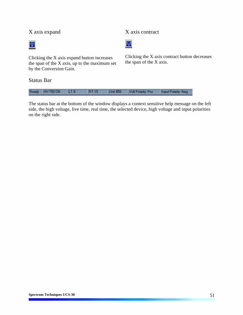
X axis expand
Clicking the X axis expand button increases the span of the X axis, up to the maximum set by the Conversion Gain.
X axis contract
Clicking the X axis contract button decreases the span of the X axis.
Status Bar
The status bar at the bottom of the window displays a context sensitive help message on the left side, the high voltage, live time, real time, the selected device, high voltage and input polarities on the right side.

Spectrum Techniques UCS-30
52
Specifications Hardware Physical: Single instrument includes preamplifier, amplifier, detector high voltage, 4096-
channel (maximum) multichannel analyzer with data memory, LLD and ULD. Fully compatible with many scintillation detectors and commercial tube bases.
Amplifier: On-board combination preamplifier/amplifier for use with scintillation detectors and PMTs. Computer controlled coarse and fine gain from x1 to x160.
ADC: Wilkinson type with 80 MHz clock and computer selected conversion gain of 4096, 2048, 1024, 512, or 256 channels. Direct input accepts pulse peaking times of 1 µsec. to 10 µsec. Includes dead-time correction when used in Live-time mode.
LLD & ULD: Lower Level- and Upper Level-discriminators. Independently computer controlled in 4-channel increments over entire input range. Operates prior to ADC for reduced system dead time.
Modes: MCA for pulse height analysis, or MCS for half-life decay or other time related studies.
Timers: Real-time or Live-time operation selectable in 1-second increments for PHA, or dwell times from 10 msec. to 600 seconds per channel in MCS mode.
Data Memory: On-board static RAM, 4096 channel (x) 3 Bytes for data, plus region-of-interest flag.
Deadtime: System dead-time is computed and displayed on screen during acquisition.
Power: AC line powered with an auto sensing power supply for 100 – 250 VAC, 10 watts total.
Connections On Rear Panel:
Rear Panel
AC POWER IN
90 — 240 VAC
50 — 60HZ
USB
WARNING:
DANGEROUS VOLTAGES INSIDE SERVICE BY AUTHORIZED
PERSONNEL ONLY
MANUFACTURED BY SPECTRUM TECHNIQUES OAK RIDGE TENNESSEE 37830
MADE IN USA
HIGH VOLTAGE
INPUTMSBOUT
T/COMPMCS IN
GATE IN
ROIOUT
PREAMP POWER WARNING:
DANGEROUS VOLTAGESON HV CONNECTORS
POS NEG

Spectrum Techniques UCS-30
53
Software System: Operates under Windows® 2000, Windows® XP with 600 kb disk space for the
executable file and 6 meg for the optional help file available disk space, 64 MB RAM (128 MB recommended), and compatible mouse.
Display: VGA or SVGA color graphics (800x600 recommended. Linear vertical scale adjusts from 64 to 16M and full range logrithmic display. Horizontal 4096 channels with reduction down to 128 channels.
Time Mode: Preset live-time or preset real-time selection. Both times are recorded and displayed.
ROIs: Multiple Regions-of Interest using color coding.
Integral: When cursor is in ROI, computes gross area, net area with end point averaging, centroid and FWHM.
Energy Cal: 2-point linear or 3-point quadratic converts cursor position reading directly to energy units. (Time units in MCS mode.)
Temp Comp: Temperature compensation adjusts high voltage to compensate for fluxuations in temperature, when using a suitable PMT base.
Strip: Subtracts channel-by-channel time normalized data stored in File Mode. Overlays two saved spectra in File Mode
Smooth: 3-point smoothing of selected displayed data.
Control: Software control of High Voltage, Amplifier Gain, Lower and Upper level discriminators, and ADC Conversion Gain.
File: Save or load data file and header information in binary or spreadsheet compatible formats.
Print: Prints current screen display to Windows printer.
ROI File: Saves ROI data, centroid, FWHM, gross and net integrals, and header information in spreadsheet compatible format.
IsoMatch: Isotope library text file with peak markers and labeling for overlaying on spectrum for quick isotope identification. Library may be edited from Edit, IsoMatch pull down menu.
Spectrum Techniques Contact
SPECTRUM TECHNIQUES, LLC. 106 Union Valley Road Oak Ridge, TN 37830
USA. Tel. (865) 482-9937 Fax. (865) 483-0473 e-mail. [email protected]
Web Site. http://www.SpectrumTechniques.com