UC-BL DUAL-AXIS ANKLE-CONTROL SYSTEM
31
UC-BL DUAL-AXIS ANKLE-CONTROL SYSTEM Casting, Alignment, Fabrication, and Fitting J . W . Campbell Associate Orthotics Staff Specialist W. H . Henderson e D . E . Patrick Assistant Orthotics Staff Specialist Biomechanics Laboratory University of California San Francisco Medical Center San Francisco, Calif . 94122 I . INTRODUCTION The University of California Biomechanics Laboratory (UC-BL) Dual-Axis Ankle-Control System was developed to answer the need for a more satisfactory method of ankle bracing than that afforded by the conventional short leg brace (1) . The name was chosen because the de- vice is essentially an external analog of normal motions about the two joint axes in the ankle complex . In this report, System designates the brace together with the equipment used for its alignment—to be de- scribed below—whereas Unit refers to the brace alone. Early studies of human locomotion established the importance of the subtalar (talocalcaneal) joint (2) as well as of the ankle (talocrural) joint (3) for walking and other activities of daily living. The conventional double-upright short leg brace is supplied with one single-axis joint which is supposed to move with the ankle joint. There is no general agreement regarding the proper, or optimum, align- ment of this brace-joint axis relative to the anatomic joint axes of the a This study was supported in part by the Easter Seal Research Foundation (the System is patented : U .S . Patent No . 3,086,521 and Canadian Patent No . 696,813) , in part by the Social and Rehabilitation Service, Department of Health, Education and Welfare Research Grants OVR RD–924–M and SRS RD–2860–M, and in part by Vet- erans Administration Contract V1005M–2075. b Also published as : Campbell, J . W., Henderson, W . H ., and Patrick, D . E . : UC-BL Dual-Axis Ankle-Control System : Casting, Alignment, Fabrication, and Fitting . Bio - mechanics Laboratory, University of California, San Francisco and Berkeley, Techni - cal Report 60 . San Francisco, The Laboratory, Jan . 1969. e Research and Education Associate, Commission on Accreditation of Rehabilitati on Facilities, Chicago, Ill . ; formerly, Associate Orthotics Staff Specialist, Biomechan ics Laboratory. 184 A
Transcript of UC-BL DUAL-AXIS ANKLE-CONTROL SYSTEM

UC-BL DUAL-AXIS ANKLE-CONTROL SYSTEM
Casting, Alignment, Fabrication, and Fitting
J . W. CampbellAssociate Orthotics Staff Specialist
W. H. Henderson e
D. E. PatrickAssistant Orthotics Staff Specialist
Biomechanics LaboratoryUniversity of California San Francisco Medical Center
San Francisco, Calif . 94122
I . INTRODUCTION
The University of California Biomechanics Laboratory (UC-BL)Dual-Axis Ankle-Control System was developed to answer the need for amore satisfactory method of ankle bracing than that afforded by theconventional short leg brace (1) . The name was chosen because the de-vice is essentially an external analog of normal motions about the twojoint axes in the ankle complex. In this report, System designates thebrace together with the equipment used for its alignment—to be de-scribed below—whereas Unit refers to the brace alone.
Early studies of human locomotion established the importanceof the subtalar (talocalcaneal) joint (2) as well as of the ankle(talocrural) joint (3) for walking and other activities of daily living.The conventional double-upright short leg brace is supplied withone single-axis joint which is supposed to move with the ankle joint.There is no general agreement regarding the proper, or optimum, align-ment of this brace-joint axis relative to the anatomic joint axes of the
a This study was supported in part by the Easter Seal Research Foundation (theSystem is patented : U .S . Patent No . 3,086,521 and Canadian Patent No . 696,813) , inpart by the Social and Rehabilitation Service, Department of Health, Education andWelfare Research Grants OVR RD–924–M and SRS RD–2860–M, and in part by Vet-erans Administration Contract V1005M–2075.
b Also published as : Campbell, J . W., Henderson, W . H ., and Patrick, D . E . : UC-BLDual-Axis Ankle-Control System : Casting, Alignment, Fabrication, and Fitting . Bio -
mechanics Laboratory, University of California, San Francisco and Berkeley, Techni -
cal Report 60 . San Francisco, The Laboratory, Jan . 1969.e Research and Education Associate, Commission on Accreditation of Rehabilitation
Facilities, Chicago, Ill . ; formerly, Associate Orthotics Staff Specialist, Biomechan ics
Laboratory.
184
A

Campbell et al . : UC-BL Ankle-Control System—Casting etc.
ankle complex . Perhaps the most commonly recommended procedure atthe present time is to try to align the brace-joint axis with the anatomicankle-joint axis . Such an attempt is almost sure to fail—primarily be-cause it ignores the subtalar joint . In addition, the brace-joint axis isusually made parallel with the floor and therefore cannot be coaxialwith the ankle-joint axis, which has been shown to lie not horizontally,but inclined downward and posteriorly from the medial to the lateralend (4) .
Any ankle brace is a compromise and provides, at best, an approxima-tion of the various movements which can take place in the normal an-kle complex . Investigation of the effects and limitations of the conven-tional brace has indicated that a somewhat more complex device, whichprovides a more precise approximation to normal motion by allowingmovement at both the ankle and the subtalar joints, would be of signifi-cant benefit to the brace wearer.
Desai and Henderson developed a complex adjustable external me-chanical analog of the ankle and subtalar joints to determine the loca-tions of, and observe the motions about, these joints . This device, andthe drop-foot brace based upon it, have been described in detail (1) .The final model of the brace worked out by them was in all essentialsthe prototype of the present UC-BL Dual-Axis Ankle-Control Unit.
The UC-BL Shoe Insert (5), developed as an adjunct to the braceand usually used with it, is a plastic shell that grips the heel firmly andholds the foot in an improved functional position within the shoe.
The present model of the brace, without attachments, allows "nor-mal" (unrestricted) motion at both the ankle and the subtalar joints.Attachments at one or both of the joints can be added to restrict, direct,or aid certain motions as desired . The brace is not, however, an all-pur-pose device. Developed originally for the correction of drop foot, it hasalso proved useful as an adjunct in the treatment of talipes equino-varus (clubfoot) . In its present form it is not suitable for use as aweight-bearing brace, because it has not been designed to withstandheavy loads.
Considerable effort has been directed toward simplifying proceduresfor fitting and alignment without impairing the desirable features ofthe brace. For several years alignment has been accomplished by fittingan adjustable brace (a simplified analog with adjustable elements) tothe patient; with this method, misalignments of the joints of the adjust-able brace are systematically eliminated until optimum fit and align-ment are achieved (6) . Alignment duplication jigs are used to transferthe alignment to the final brace.
Recently, a further simplification in fitting was introduced which al-lows the orthotist to align and construct the Dual-Axis Unit in a frac-
185

Bulletin of Prosthetics Research—Spring 1969
tion of the previously required time . This report describes the simpli-fied technique, in which a plaster wrap cast is taken of the patient's legand foot with his shoe on, and this cast is used as a basis for the align-ment and construction of the final brace.
The new procedure is based on anthropometric studies of the footand ankle which were completed within the last year by Isman and In-man (4) . Many investigators (7, 8, 9) have in the past considered theankle joint to be a multi-axis joint—notably Hicks (9) , who believedthat there were separate plantar-flexion and dorsiflexion axes . On thebasis of their own studies, Isman and Inman (4) and Inman (10) statethat the ankle joint is close enough to being a single-axis joint that forpurposes of bracing it may be considered as such ; they also determinedthat this axis could be approximately located as a line connectingpoints 3 to 5 mm. distal to the distal tips of the lateral and medial mal-leoli (Fig . 1) .
The investigation of Isman and Inman further indicated that the av-erage inclination of the subtalar axis is 41 deg . from the horizontal d
(most authorities agree that this inclination is approximately 40 deg . e )
FIGURE 1 FIGURE 2
d In the following, the horizontal plane is the plane of or parallel to the floor orother standing surface.
e It should be pointed out that the angle of the subtalar joint of the brace willrarely be set at exactly 40 deg, from the floor . This is due to (1) variations in anat-omy and (2) the necessity of placing the heel joint at the junction of the shoe's heeland heel counter, rather than at the actual point of emergence of the axis from thepatient's foot.
186

Campbell et al . : UC-BL Ankle-Control System—Casting etc.
and that it intersects or passes slightly below the ankle-joint axis approx-imately halfway between the tips of the malleoli (Fig . 2) . For purposesof bracing, actual intersection can be assumed, in which case, of course,the two axes lie in a single plane. The relationship between the twobrace-joint axes can be visualized by rotating this plane about the ankleaxis until the axis of the subtalar joint within the plane is inclined toapproximately 40 deg. (Fig . 3) .
The method of making the brace may be briefly summarized as fol-lows : The locations of the distal tips of the malleoli are marked withindelible pencil . A thin-walled plaster wrap is taken of the patient's leg,with the wrap carefully molded to the shoe at the same time . When thewrap and the shoe are removed from the patient and the wrap is re-paired and keyed back onto the shoe, a steel pin is inserted through thepoints on the wrap that mark the tips of the malleoli . The pin repre-sents the ankle axis,' and the cast, shoe, and pin provide a model withall of the necessary information for alignment.
The heel joint, which corresponds to the subtalar joint, is preset andfixed in a position 15 deg. medial to the long axis of the shoe . g Adjusta-ble components are now used to link the heel joint to the ankle joint insuch a way as to hold them in the common plane referred to in Figure 3and to maintain within that plane the relative angle formed by the twoaxes .
FIGURE 3
f Although the ankle-joint axis passes through points approximately 3 to 5 mm . dis-tal to the distal tips of the malleoli, an axis that passes through the distal tips is suf-ficiently accurate for purposes of bracing.
g This line represents the projection of the subtalar axis on a horizontal plane . Thediscrepancy between this angle (15 deg.) and the average found by Isman and In-man (23 deg.) is explained by the fact that the long axis of the shoe runsapproximately through the second ray and is thus closer to the line representing theaxis of the subtalar joint than is the midline assumed by Isman and Inman, whichruns midway between the second and third rays .
187

Bulletin of Prosthetics Research—Spring 1969
The alignment maintained by the adjustable components is trans-ferred to permanent parts by means of special tools, i .e ., protractor,bending jig, and alignment transfer jig . When the permanent parts arereassembled on the shoe and the sidebar and cuff have been bent to theshape of the wrap, the unit is complete. Fit is checked on the patient,and assists are added and subtracted as needed.
II . PARTS AND EQUIPMENT
Brace Hardware and Equipment
The UC-BL Dual-Axis Ankle-Control Unit (Fig. 4) comprises threebasic links : the stirrup, yoke, and sidebar assemblies . Of these, the stir-rup and the yoke require adjustable brace counterparts and alignmenttransfer jigs.
The stirrup assembly includes the channel which is attached to theshoe and the stirrup which is the link between the shoe and the heeljoint . The stirrup slides into and out of the channel ; this arrangementmakes it possible to disconnect the brace from the shoe quickly. Parts:channel and stirrup . Tools : adjustable stirrup, stirrup-bending jig, andprotractor.
The stirrup and the yoke are held together at the heel joint by aflanged nut, a flanged screw, a locking screw, and Nylatron washers (seeFig . 35) . Tools : special spanner wrenches.
The yoke assembly consists of the tang which constitutes half of theheel joint and the tongue which constitutes half of the sidebar joint.
SIDEBARJOINT
188
Campbell et al . : UC-BL Ankle-Control System—Casting etc.
Parts : tang and tongue (which, when joined together, comprise theyoke) and one lacing hook. Tools : adjustable yoke, shortened sidebar-joint pivot nut, center-drilled ankle-joint-alignment machine screw,yoke alignment transfer jig, bending irons, and acetylene welding torch.
The yoke and sidebar are held together at the sidebar joint by a side-bar-joint pivot nut and a sidebar-joint screw.
The sidebar assembly consists of a standard commercially availablealuminum or steel sidebar (which incorporates either a Klenzak jointor a free ankle joint) and a cuff which is the link between the sidebarjoint and the shank of the leg. Parts : commercially available sidebar(the Klenzak joint has a setscrew, a steel toe-lift spring, and a steel ballwhich, for this brace, is replaced by a Nylatron reaction plug) , cuffband made of 16-gage aluminum, 1 i/2-in . wide, leather, rubber (1/8 -in.Kemblo Cel-flex) for the liner, Velcro or leather strap fasteners . Tools:bending irons.
To provide eversion assistance, rubber bands are stretched between areaction stud in the heel and the lacing hook of the yoke . The reactionstud, a 11/2 -in . #8 plated screw, is screwed into the heel, leaving a ]A-in.space between the heel and the head of the screw.
In addition to the items listed above, a pair of suitable shoes must beprovided by the patient . They will be used during the casting proce-dure and must be retained by the orthotist for use in fabrication of thebrace . The shoes should be sturdy laced oxfords with metal shanks . Forwomen, laced oxfords or nurses' type shoes are required; the heel mustbe no higher than 1 in.
Stock Tools and Supplies
It is assumed that fabrication will be done in an orthotics shop outfit-ted with standard equipment . Specific supplies for fabrication of theUC-BL Dual-Axis Ankle-Control Unit would include the following:
% 2 -in . drill#3, #19, and #29 wire-gage drills#8–32 tap8–32 flat head machine screws#10 standard brass rivets, 1 in . long#4829 Speedy rivetheel nails7-in . bandage scissors or a cast cutterone pair 7-in . bow-spring outside calipers
machinist's square or similar right-angle instrumenttrisquare combination tool with two circle-bisecting attachments
"C" clamps, 6-in . opening
189

Bulletin of Prosthetics Research—Spring 1969
leather punchhand pump for inflating balloonsrubber bands, size 10 or 12balloons (airship, colorless, manufactured by Ashland Rubber Prod-
ucts, Ashland, Ohio 44805, #836 for adults, #625 for children)1A-in . or 3/$ - in . rubber tubing, 24 in . to 30 in . long1/2 -in . double-sided adhesive tapemasking tapeindelible pencilssteel pin, %2 in. in diameter and 9 in . longlead strips, approximately 1/8 in . x 1 in . x 8 in.small scraps of leather for build-up on heel around channelshoe glue, such as Sta-Bondbaby powdergrease or petroleum for rubber tubing3-in . stockinet (2-in . for children)4-in. rolls of fast-setting elastic plaster, Johnson and Johnson Ortho-
flexconventional plaster bandage for cast repair
Ill . CASTING PROCEDURE
1. Place a clean sheet of paper on the standing surface, since any sharpbits of hardened plaster from previous casting procedures will easilytear the balloon that is used during casting.
2. Have the patient don his shoes without stockings . If he wears anydevice such as an arch support or shoe insert, it should also be wornduring casting.
3. Seat the patient in such a way that he can comfortably hold his af-fected leg extended.
4. Place a 1-in. strip of double-sided adhesive tape over the tip ofeach malleolus to help mold the balloon, and subsequently the cast,to these areas.
5. Powder the inside of an appropriately sized balloon ; this is easilydone by stretching the opening over the mouth of a small containerof baby powder and shaking . Then inflate the balloon fully andplace it with the closed end against the anterior end of the extendedshoe of the patient (Fig . 5).
6. Push the balloon carefully onto the shoe past the heel . Release airgradually until the balloon is completely deflated (Fig . 6) . To con-trol the release of air and maintain control over the balloon, holdthe open end of the balloon against the abdomen while using bothhands to guide the balloon onto the foot . Trunk movement is usedto control the rate of air release.
190
1
Campbell et al . : UC-BL Ankle-Control System—Casting etc.
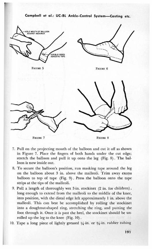
FIGURE 5 FIGURE 6
FIGURE 7 FIGURE 8
7. Pull on the projecting mouth of the balloon and cut it off as shownin Figure 7. Place the fingers of both hands under the cut edge;stretch the balloon and pull it up onto the leg (Fig. 8) . The bal-loon is now inside out.
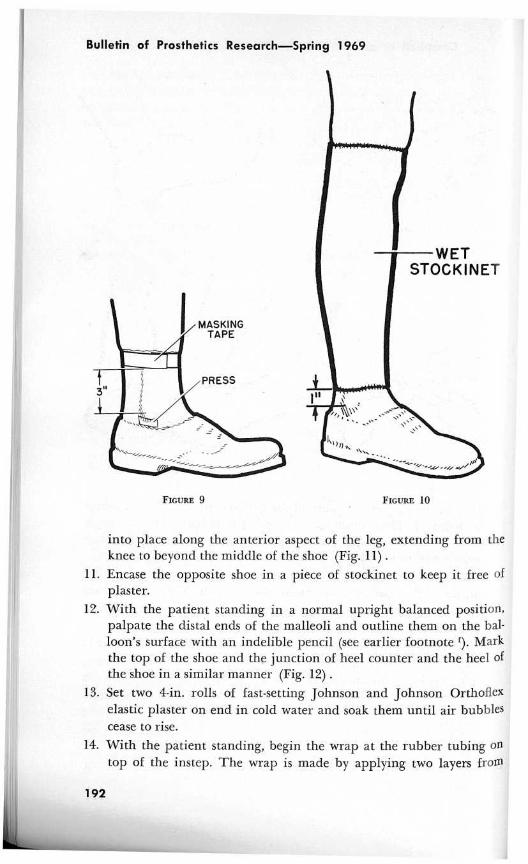
8. To secure the balloon's position, run masking tape around the legon the balloon about 3 in. above the malleoli . Trim away excessballoon to top of tape (Fig . 9) . Press the balloon onto the tapestrips at the tips of the malleoli.
9. Pull a length of thoroughly wet 3-in . stockinet (2 in . for children) ,long enough to extend from the malleoli to the middle of the knee,into position, with the distal edge left approximately 1 in . above themalleoli . This can best be accomplished by rolling the stockinetinto a doughnut-shaped ring, stretching the ring, and putting thefoot through it . Once it is past the heel, the stockinet should be un-rolled up the leg to the knee (Fig . 10) .
10. Tape a long piece of lightly greased IA-in . or sus-in . rubber tubing
191
Bulletin of Prosthetics Research—Spring 1969
FIGURE 9
FIGURE 10
into place along the anterior aspect of the leg, extending from theknee to beyond the middle of the shoe (Fig . 11) .
11. Encase the opposite shoe in a piece of stockinet to keep it free ofplaster.
12. With the patient standing in a normal upright balanced position,palpate the distal ends of the malleoli and outline them on the bal-loon's surface with an indelible pencil (see earlier footnote D . Markthe top of the shoe and the junction of heel counter and the heel ofthe shoe in a similar manner (Fig . 12) .
13. Set two 4-in . rolls of fast-setting Johnson and Johnson Orthoflexelastic plaster on end in cold water and soak them until air bubblescease to rise.
14. With the patient standing, begin the wrap at the rubber tubing ontop of the instep. The wrap is made by applying two layers from
192

Campbell et al . : UC-BL Ankle-Control System—Casting etc.
FIGURE 11 FIGURE 12
the dorsum to the bottom of the heel (Fig. 13) . Then begin an up-ward spiral wrap, with each successive layer overlapping the pre-vious one by half the bandage width, or 2 in.
15. Continue the spiral upward to the popliteal crease (Fig . 14) . Wraptwice around the crease and then make a downward spiral wrapsimilar to the previous upward one (with the same type of overlap-ping layers) . The purpose of this controlled wrap is to provide auniform thickness between the fibular head and the malleolar areas.The proper contour of the sidebar and fit of the cuff depend uponthis uniform thin cast.
16. Smooth and mold the entire wet wrap into the areas around themalleolar tips and the top of the shoe counter.
17. Remove the rubber tubing after the cast has hardened . This will ex-
193

Bulletin of Prosthetics Research—Spring 1969
FIGURE 13 FIGURE 14
pose a cutting channel adequate to allow the use of a standard pairof bandage scissors or a cast cutter.
18. Remove the cast, retain the shoe, and dismiss the patient.19. Repair the cast by closing its cut edges with short strips of conven-
tional plaster bandage, taking care to avoid extending the patch tothe lateral aspect of the leg, where a plaster build-up would hamperthe achievement of a smooth brace sidebar contour . Let the cast drynaturally at room temperature or place it in an oven at 150 deg. F.for 1 hour.
IV. ALIGNMENT, FABRICATION, AND FITTING : DETAILEDPROCEDURE
1. The marks made over the tips of the lateral and medial malleoliwill be clearly visible on the inside of the cast . Transfer these marksaccurately to the outside of the cast with a pair of 7-in . bow-springoutside calipers or a similar device (Fig . 15) .
2. Drill a %2-in . hole through the cast at each of the two malleolarmarks.
194

Campbell et al . : UC-BL Ankle-Control System—Casting etc.
FIGURE 15
FIGURE 16
3. Insert a pin, %2 in. in diameter and approximately 9 in . long,through the malleolar holes . This pin approximates the patient'sankle-joint axis.
4. Trim the cast to the line marking the junction of the heel and theheel counter.
5. Stuff the shoe with paper to prevent distortion.6. Replace the cast on the shoe ; key it along the top edge of the shoe
counter, using the previously molded ridges.7. With a machinist's square or similar right-angle instrument, estab-
lish and mark the medial and lateral points along the sides of theheel portion of the sole where vertical lines would bisect the linesmarking the distal ends of the malleoli (Fig. 16) .
8. Remove the cast from the shoe . Take the heel off the shoe . If a plas-tic spacer is present between the sole and the heel, remove and dis-card it, and sand the heel portion of the sole flat . Shoe constructionvaries, and in some cases a skived leather insert is present betweenthe heel and the sole. If this insert comes off in the process of re-moving the heel, glue it back into place and lightly sand it to insurea flat surface.
9. Draw a connecting line (Fig. 17) on the flattened heel portion ofthe sole between the two marks made in Step 7 .
195

Bulletin of Prosthetics Research—Spring 1969
FIGURE 17
FIGURE 18
10. Draw a center line (see earlier footnote g ) along the length of thesole ; to do this, use the rule of a trisquare combination tool whichhas two circle-bisecting attachments fitted to opposite ends, one cup-ping and bisecting the heel, the other cupping and bisecting the an-terior end of the sole (Fig . 18) . A "C" clamp placed at the heel willgreatly assist in holding the rule in place while the line is drawn.
11. Using the point of intersection of the line drawn across the heel andthe longitudinal line just drawn, draw another line passing 15 deg.medial to the longitudinal line on the forefoot portion (Fig . 19) .This line approximates the axis of the subtalar joint projected on ahorizontal plane (see earlier footnote g) .
196

Campbell et al . : UC-BL Ankle-Control System—Casting etc.
FIGURE 19
CHANNEL
FIGURE 20
SCRIBE CENTER LINE
12. Drill two pairs of holes with a #29 wire-gage drill, one pair oneach end of a channel—one set of holes 1 in . from one end and theother set of holes 1/2 in. from the other end. Tap these holes to#8–32 threads . Scribe a center line on the channel (Fig . 20)
13. Remove the paper and the heel liner from inside the shoe . Centerthe channel over the subtalar, or 15 deg ., angle line, with that endof the channel that has the holes 1 in . from the end placed poste-riorly and with the center of the posterior end 1/8 in . inside the heelmargin (Fig . 21) . Hold the channel in place with a "C" clamp.
14. Using one of the tapped holes as a drill guide, drill a hole through
197

Bulletin of Prosthetics Research—Spring 1969
FIGURE 21
FIGURE 22
the sole into the shoe with a #29 drill . Holding the channel in po-sition temporarily with a rivet through this hole, drill the hole onthe opposite corner . Again, place a rivet in the hole while the lasttwo holes are drilled.
15. Remove the rivets and the channel and drill through all four holesin the shoe again with a #19 drill . Fix the channel in place withflat head machine screws inserted from the inside of the shoe andtightened until the heads are flush with the insole.
16. Invert the shoe and grind or file the tips of the screws flush with the
198
1

r
Campbell et al . : UC-BL Ankle-Control System—Casting etc.
channel surface. Trim and sand all protruding corners of the chan-nel (Fig . 22) .
17. Connect the adjustable yoke to the adjustable stirrup, and insert thestirrup into the channel (Fig. 23) .
18. Replace the cast once again in the manner described in Step 5.19. Place the shortened sidebar-joint pivot nut into the medial side of
the hole in the tongue portion of the adjustable yoke, and screw thecenter-drilled ankle-joint-alignment screw into the nut (Fig . 24).
FIGURE 23
FIGURE 24
FIGURE 25
199

Bulletin of Prosthetics Research—Spring 1969
20. With all of the adjustable components loose, adjust the yoke andstirrup until the ankle-joint pin can pass freely through the centerof the machine screw and the holes in the cast which mark the an-kle-joint axis; leave approximately in . clearance between theprojection marking the lateral malleolus and the inner aspect of thetongue. The tongue should be perpendicular to the ankle-joint pin(Fig . 25) .
21. Lock all of the adjustable components and bend a strip of lead tofollow the contour of the shoe from the heel joint to the sidebarjoint; it should be at a uniform distance of approximately in.from the shoe and the cast (Fig . 26) .
22. Invert the shoe and, with a #29 drill, drill a hole through both thechannel and the shoe . The pilot for this stirrup alignment hole is inthe base of the adjustable stirrup (Fig . 27) .
23. Remove the cast, the adjustable yoke, and the adjustable stirrup.
24. Measure the angle between the heel-joint surface of the adjustablestirrup and its base (Fig . 28) .
FIGURE 26 FIGURE 27
200

Campbell et al . : UC-BL Ankle-Control System—Casting etc.
STIRRUP-BENDING JIG
FIGURE 29
25. Place a stirrup blank in the bending jig with the narrower side upand clamp it to the base in a centered position. Then bend theblank (Fig. 29) to the angle measured in Step 24.
26. Align the transfer jig to the adjustable yoke and lock all of the jig'sadjustments (Fig. 30) .
27. Remove the adjustable yoke from the jig . Put a yoke tang into thestirrup-bending jig and bend it to a 45 deg . angle . This is done be-cause the initial bend of the yoke tang is so close to the bearing sur-
FIGURE 28
201

Bulletin of Prosthetics Research—Spring 1969
YOKE ALIGNMENT TRANSFER JIG
HEELJOINT
ADJUSTABLE YOKE
FIGURE 30
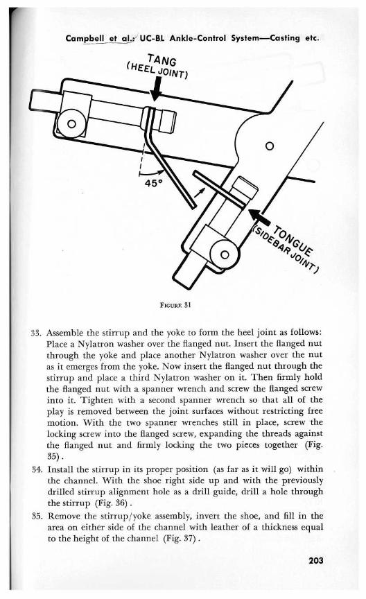
face that bending irons would not work and a vise technique mightdamage or warp the machined bearing surface . Install the bent tangand a tongue blank in the yoke transfer jig in their appropriate po-sitions (Fig. 31).
28. Bend the two components (Fig . 32) until they mate and approxi-mate the contour of the lead strip (Step 21) . (Bend the tang firstand then bend the tongue as necessary to mate with it .)
29. Mark the tang for proper length, allowing for an overlap of
in.30. Remove the tang and the tongue from the jig, cut the tang to
length, and sand or grind a bevel on each of their overlapping ends.31. Replace the tongue and the tang in the transfer jig, and silver braze
their mating surfaces together (Fig. 33) . To prevent metal-burn, itis good practice to braze the beveled edges first and then the sidesurfaces . Cool the yoke, remove it from the jig, and clean and polishit.
32. Attach a lacing hook to the inner aspect of the yoke, approximatelymidway between the sidebar joint and the heel joint, with the open-ing upward (Fig. 34) .
202
Campbell et alJ% UC-BL Ankle-Control System—Casting etc.
(HEELQOIN T)
FIGURE 31
33. Assemble the stirrup and the yoke to form the heel joint as follows:Place a Nylatron washer over the flanged nut . Insert the flanged nutthrough the yoke and place another Nylatron washer over the nutas it emerges from the yoke . Now insert the flanged nut through thestirrup and place a third Nylatron washer on it . Then firmly holdthe flanged nut with a spanner wrench and screw the flanged screwinto it . Tighten with a second spanner wrench so that all of theplay is removed between the joint surfaces without restricting freemotion. With the two spanner wrenches still in place, screw thelocking screw into the flanged screw, expanding the threads againstthe flanged nut and firmly locking the two pieces together (Fig.35) .
34. Install the stirrup in its proper position (as far as it will go) withinthe channel . With the shoe right side up and with the previouslydrilled stirrup alignment hole as a drill guide, drill a hole throughthe stirrup (Fig. 36) .
35. Remove the stirrup/yoke assembly, invert the shoe, and fill in thearea on either side of the channel with leather of a thickness equalto the height of the channel (Fig. 37) .
203
Bulletin of Prosthetics Research—Spring 1969
FIGURE 32
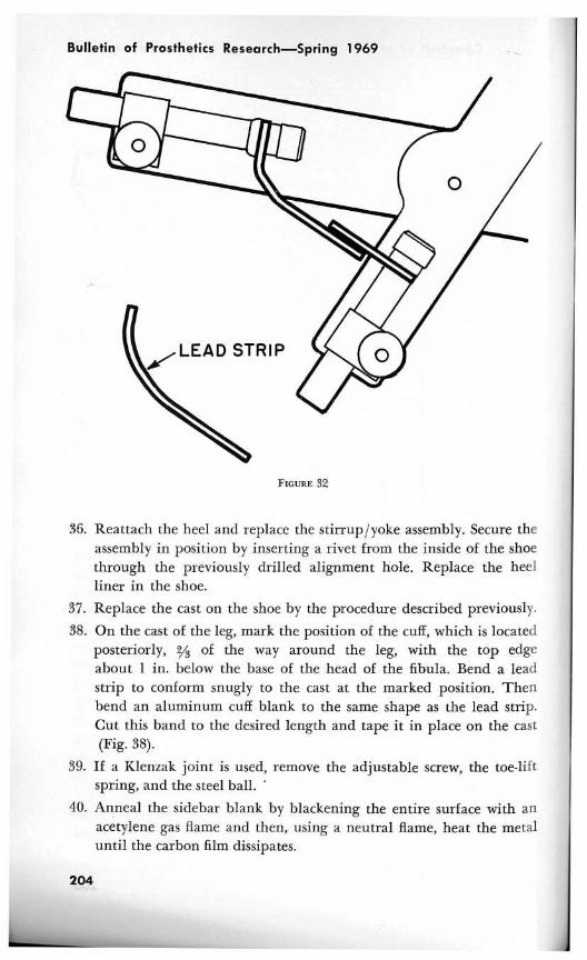
36. Reattach the heel and replace the stirrup/yoke assembly . Secure theassembly in position by inserting a rivet from the inside of the shoethrough the previously drilled alignment hole . Replace the heelliner in the shoe.
37. Replace the cast on the shoe by the procedure described previously.
38. On the cast of the leg, mark the position of the cuff, which is locatedposteriorly, 2/s of the way around the leg, with the top edgeabout 1 in. below the base of the head of the fibula . Bend a leadstrip to conform snugly to the cast at the marked position . Thenbend an aluminum cuff blank to the same shape as the lead strip.Cut this band to the desired length and tape it in place on the cast(Fig. 38).
39. If a Klenzak joint is used, remove the adjustable screw, the toe-liftspring, and the steel ball.
40. Anneal the sidebar blank by blackening the entire surface with anacetylene gas flame and then, using a neutral flame, heat the metaluntil the carbon film dissipates.
204

rCampbell et al . : UC-BL Ankle-Control System_Casting etc.
FIGURE 33
41. Using the ankle-joint-alignment machine screw, attach the sidebarblank to the yoke.
42. Insert the ankle-joint pin through the malleolar holes and the an-kle-joint-alignment machine screw.
43. Bend the sidebar with bending irons into a snug fit over the con-tours of the cast and the cuff (Fig . 39) .
44. Mark the sidebar where it crosses the proximal and distal borders ofthe cuff band (Fig. 40) . Mark the position of the sidebar on thecuff band.
45. Remove the sidebar. Drill and tap two holes in the sidebar for #8-
205

Bulletin of Prosthetics Research—Spring 1969
FIGURE 34
FIGURE 35
32 machine screws, one 1/4 in. below the proximal cuff margin markand the other 1/ in. above the distal mark.
46 . Cut the sidebar to length at the proximal cuff margin, sand andpolish it, and refit it into the sidebar joint using the permanent side-bar-joint pivot nut and sidebar-joint screw instead of the shortenedsidebar-joint pivot nut and the center-drilled ankle-joint-alignmentmachine screw.
206
1

Campbell et al . : UC-BL Ankle-Control System—Casting etc.
FIGURE 36 FIGURE 37
47. Mark the positions of the two #8-32 tapped sidebar holes on thecuff band. Remove the band and drill two holes with a #3 wire-gage drill . Also with a #3 drill, drill a hole in the opposite end ofthe band, centered
in . from the end (Fig . 41) .48. Using ½-in . Kemblo Cel-flex or a similar suitable material, make a
cuff liner the shape of the inside surface of the cuff band allowingfor a ½-in. overlap on all sides . Enclose this liner with a light horse-hide cover . Glue the completed liner to the inside surface of the cuffband, and punch three holes in the liner through the three holes inthe cuff band .
207

Bulletin of Prosthetics Research—Spring 1969
FIGURE 38
FIGURE 39
FIGURE 40
208
A

f
Campbell et al . : UC-BL Ankle-Control System—Casting etc.
FIGURE 41
FIGURE 42
49. Center and glue a strip of Velcro hook the same length as the cuffto the outside surface of the cuff ; punch holes in this, also, over thethree cuff band holes . Fix a #4829 Speedy rivet in the single holeon the medial side of the cuff.
50. Cut a strip of Velcro pile in a length adequate to encircle the leg.Press the end of the strip on to the lateral side of the cuff band sothat it is 1/4 in. posterior to the pair of holes, and punch it over theholes. The long part of the strip will now extend anteriorly (Fig.42) .
51. Pass two #8-32 machine screws through the liner, cuff band, Velcrohook, and Velcro pile and tighten them in the tapped #8-32 holeson the sidebar . This arrangement holds all of the materials firmlyin place.
52. Make a pretibial pad of Naugahyde or leather approximately thewidth of the cuff opening, with webbing slots to receive the strip ofVelcro pile . Thread the strip of pile into the pretibial pad . The side-bar assembly is then complete.
53. Screw the reaction stud into the lateral side of the heel portion ofthe sole, at approximately the anterior end of the heel (as shown onthe completed brace in Figure 43) .
54. The overall heel heights in both shoes should be checked to makesure that they are equal.
55. Summon the patient and fit him with the brace . Mount a few rub-ber bands between the reaction stud on the shoe and the lacinghook on the yoke to provide eversion assistance . When a Klenzaksidebar is used for the patient requiring toe-lift, replace the steelball with the special Nylatron reaction plug . Re-install the toe-liftspring and the adjustment screw . Ask the patient to walk . After ob-serving his gait, add or subtract rubber bands and adjust the toe-liftspring screw as required for optimum assistance at each joint.
56. Should damage or general wear require duplication of a particularbrace at a later date, refitting of the patient is unnecessary . Fabrica-
209

Bulletin of Prosthetics Research—Spring 1969
FIGURE 43
tion of a completely new brace is very simple if the cast has been re-tained by the patient and the orthotist has kept a record of (1) size,model, and manufacturer of the shoe; (2) the angle of stirrupbend; (3) the angle formed by the two arms of the yoke alignmenttransfer jig ; and (4) the distance from the pivot point of the trans-fer jig to the center of the bolt holding the tang in place, and thedistance from the pivot point to the center of the bolt holding thetongue in place. Separate replacement of either the stirrup or theyoke is also conveniently accomplished with use of these data.
V. CLINICAL EXPERIENCE
Clinical experience with the UC-BL Dual-Axis Ankle-Control Unithas not yet included a great variety of conditions, nor has the sample ofsubjects been large enough to allow a valid statistical analysis . The con-clusions and comments reported here have been compiled from patientrecords maintained by physicians and orthotists at the BiomechanicsLaboratory.
The brace has been prescribed primarily for patients who, as a resultof poliomyelitis or peripheral nerve damage, have flaccid paralysis ofthe musculature of either the anterior or peroneal compartments of the
210

r
Campbell et al . : UC-BL Ankle-Control System—Casting etc.
lower leg, with little or no bony abnormality. This is the type of de-formity with which we have had the most experience and for which thisbrace has proved most successful.
Originally, another important area of application was thought to bethe correction of bony and soft-tissue defects . In an attempt to bring thefoot into a corrected position and maintain the correction, the combina-tion of the UC-BL Shoe Insert and the UC-BL Dual-Axis Ankle-ControlUnit was used on children with talipes equinovarus deformities . The in-itial group of subjects were children who had a recurring highly resist-ant type of clubfoot with limited ranges of joint motion . As statedearlier, the corrective forces applied by the brace are transmittedthrough the shoe and the insert to the foot, and in this group of pa-tients these forces usually proved to be so great that breakdown of theskin over bony prominences resulted.
However, when used as an adjunct to standard early orthopedic treat-ment, such as serial wedge castings or serial castings, the shoeinsert/brace combination has proved much more successful . In patientswith clubfoot which has recurred after serial wedge castings, a new se-ries of casts is applied in order to achieve a slight overcorrection and aflexible foot. The final cast is removed in a bivalve manner and thecasts for both a shoe insert and a brace are made. The bivalve cast isreapplied as a holding mechanism until the brace and shoe insert canbe fabricated and fitted to the patient . Although regression occurred insome of these patients with highly resistant clubfoot, their feet have re-mained much more flexible than those of patients who have not wornthe insert/brace combination . Because the brace is rarely considered forsuch patients until several serial castings or serial wedge castings havebeen applied without success, it is difficult to estimate the true val, le ofthe insert/brace combination . When used as a postsurgical supplementto such procedures as plantar stripping, ankle capsulotomy, andAchilles-tendon lengthening in children for whom such procedures arerequired to correct fixed deformities, the combination has proved to besuccessful.
Some experience has also been gained with patients with other disa-bilities . The brace has been fitted to two patients with mild cerebralpalsy, several with hemiplegia, and several with progressive peronealatrophy. Success has been mixed. It would appear that, as has proved tobe the case with patients with clubfoot, a screening study, by a team ofphysicians and orthotists, is necessary to identify the specific types of dis-ability which could be successfully treated with the UC-BL Dual-AxisAnkle-Control Unit .
211

Bulletin of Prosthetics Research—Spring 1969
Before discussion of the limitations and advantages of the UC-BLUnit, it should be emphasized that the conventional drop-foot braceserves a number of useful purposes . The UC-BL Dual-Axis Ankle-Con-trol System should be considered an added component in the orthoticsarmamentarium.
Patient response to the UC-BL Unit has been quite interesting . Somepatients who have previously worn a single-axis drop-foot brace feel in-secure with the increased freedom of motion and without the heavytoe-lift spring action provided by a double-sidebar toe-lift brace (al-though the UC-BL Unit with its single sidebar produces an adequatetoe lift) . Others adapt `immediately without any difficulty . For many pa-tients, the convenience of a heavy toe-lift spring pick-up during levelwalking is offset by the inconvenience that the conventional brace causesduring all the other activities of daily living.
In its present form, the UC-BL Dual-Axis Ankle-Control Unit is not aweight-bearing brace, nor can it be used with the anterior or posteriorstops employed to simulate the action of the muscles which prevent toe-slap and assist toe-off. A stop to limit excessive inversion is currentlybeing tested, but its influence on the brace and the patient has yet to bedetermined.
The design of the UC-BL Dual-Axis Ankle-Control Unit is such thatthe wearer must exercise considerably more care in its use and handlingthan is necessary with the conventional short leg brace . For instance, ifa patient repeatedly bumps the heel joint during walking down stairs,misalignment may result . Shoes must be kept in good repair, becausemisalignment of the heel joint may also occur as a result of a worn-down heel, which can cause the heel joint to be exposed and struckagainst the walking surface. The rubber bands eventually deteriorateand should be replaced by the patient as necessary . Children, unaccus-tomed to the added freedom of motion afforded by the brace, may fallduring running and playing, thereby often bending and misaligning thejoints of the brace.
Within these limitations, a number of advantages of the UC-BLDual-Axis Ankle-Control Unit have become apparent through both pa-tient response and investigator observation . It is obvious to the trainedobserver that patients with a unilateral disability walk with a more sym-metrical gait when they use the Dual-Axis Unit . In most cases, there is adiminished tendency to circumduct the leg, which indicates that carefulplacement of the foot on the ground is less critical, since the foot canadjust to the angle created between the leg and the walking surface . Insome instances, excessive knee flexion has also been diminished, proba-bly because toe-lift is not merely a function of dorsiflexion about the
212

Campbell et al . : UC-BL Ankle-Control System—Casting etc.
ankle axis but is accomplished by a combination of such dorsiflexionwith eversion about the subtalar axis . This becomes more apparent whena patient with isolated peroneal weakness and relative drop-foot is fit-ted with the dual-axis brace without a toe-lift spring in the sidebarjoint. Eversion is the only assistance supplied for patients in this in-stance, and they walk exceedingly well.
In general, patients indicate that with the Dual-Axis Unit their activitylevel and endurance are greatly improved . In a nonlaboratory atmos-phere, however, any changes in energy expenditure resulting from amore symmetrical and efficient gait are difficult to assess . Because theDual-Axis Brace is considerably lighter than the conventional single-axisdrop-foot brace, one might assume that expenditure of energy would beless than that resulting from the use of a single-axis brace . This assump-tion is supported by data from studies by Ralston, which showed thataddition of weights to an extremity without restriction of joint motionproduced substantial increases in energy expenditure (11) .
The patients' most consistent praise for the Dual-Axis Unit applies toactivities which require more subtalar motion than is involved instraight and level walking. Some of the patients' comments follow ; theyare listed roughly in order of frequency.
There is a great increase in the ability to walk through crowdedareas in which one must continually change directions.
It is easier to walk up and down stairs and on uneven terrain.It is easier to get into and out of a car.
It takes less effort to move the right foot from the gas pedal tothe brake and back to the gas pedal.
It is possible. to adopt a sitting or squatting position in any man-ner and still have the braced foot flat on the ground.
Running and playing (in children with isolated muscle weak-ness) is accomplished without the halting gait which interrupts thesmoothness of their activities.
It is easier to ride a bicycle.
Children with isolated muscle weakness have, in fact, completely rejecteda return to a standard brace after a few days of use . Numerous otherresponses which relate to variations in an individual's occupation andmanner of living have also been reported.
Some patients with newly fitted Dual-Axis Units tend to rush into ac-tivities which they previously avoided . Injury and further incapacita-tion may result unless the patient is cautioned to diversify his activitiesslowly . Only gradually does he understand the limitations imposed byhis disability and the restraints he must exercise even with an effective,carefully fitted brace . However, with reasonable care of the brace and
213

Bulletin of Prosthetics Research—Spring 1969
with gradual testing of the additional activities that can be undertaken,the patient will soon enjoy the new freedom of movement allowed bythe UC-BL Dual-Axis Ankle-Control Unit.
REFERENCES
1. DESAI, S . M. and W. H . HENDERSON : Engineering Design of an Orthopedic Brace.Biomechanics Laboratory, University of California, San Francisco and Berkeley,Technical Report 45 . San Francisco, The Laboratory, Oct . 1961, 44 pp.
2. CLOSE, J . R. and V. T . INMAN : The Action of the Subtalar Joint . Prosthetic De-vices Research Project, Institute of Engineering Research, University of Califor-nia, Berkeley, Ser. 11, Issue 24 . Berkeley, The Project, May 1953, 7 pp . + illus.
3. CLOSE, J . R. and V. T . INMAN : The Action of the Ankle Joint . Prosthetic DevicesResearch Project, Institute of Engineering Research, University of California,Berkeley, Ser. 11, Issue 22 . Berkeley, The Project, April 1952, 14 pp . -I- illus.
4. ISMAN, R. E. and V . T. INMAN : Anthropometric Studies of the Human Foot andAnkle. Biomechanics Laboratory, University of California, San Francisco andBerkeley, Technical Report 58 . San Francisco, The Laboratory, May 1968, 33 pp .h
5. HENDERSON, W. H. and J . W. CAMPBELL : UC-BL Shoe Insert : Casting and Fabri-cation . Biomechanics Laboratory, University of California, San Francisco andBerkeley, Technical Report 53 . San Francisco, The Laboratory, Aug . 1967, 22 pph
6. LAMOREUX, L. W. : UC-BL Dual-Axis Ankle-Control System : Engineering Design.Biomechanics Laboratory, University of California, San Francisco and Berkeley,Technical Report 54 . San Francisco, The Laboratory, Jan . 1969 .i
7. BARNETT, C. H. and J . R . NAPIER: The Axis of Rotation at the Ankle Joint inMan . J . Anat ., 86 : 1-8, 1952.
8. KRAUSE, W. : Handbuch der Anatomie des Menschen . Leipzig, S . Hirzel, 1903, p.99.
9. Hicxs, J . H . : The Mechanics of the Foot : I . The Joints . J . Anat ., 87 : 345-357,1933.
10. INMAN, V. T . : UC-BL Dual-Axis Ankle-Control System and UC-BL Shoe Insert:Biomechanical Considerations. Biomechanics Laboratory, University of California,San Francisco and Berkeley, Technical Report 56 . San Francisco, The Laboratory,Jan. 1969 .1
11. RALSTON, H. J . : Effects of Immobilization of Various Body Segments on theEnergy Cost of Human Locomotion . Proc. 2nd I .E .A . Conference, Dortmund,1964 . [Supplement to] Ergonomics, pp . 53-60, 1965.
h Reprinted in this issue of the Bulletin.i Printed in this issue of the Bulletin.
214