UBC Technical Guidelines Division 26 UBC Vancouver and UBC ...
UBC PUMP HOUSE REPLACEMENT
UBC Pump House Replacement
Geotechnical Report
April 15, 2019
Prepared for: University of British Columbia 1100 - 2329 West Mall Vancouver, BC V6Z 1Z4 Prepared by: Stantec Consulting Ltd. 500 – 4730 Kingsway Burnaby, BC V5H 0C6
UBC PUMP HOUSE REPLACEMENT
Table of Contents
1.0 INTRODUCTION .......................................................................................................... 1.1 1.1 REFERENCE DOCUMENTS ....................................................................................... 1.1 1.2 PROJECT UNDERSTANDING ..................................................................................... 1.1
2.0 SITE DESCRIPTION AND GEOLOGY ......................................................................... 2.2 2.1 PHYSICAL SETTING ................................................................................................... 2.2 2.2 GEOLOGICAL SETTING.............................................................................................. 2.2
3.0 GEOTECHNICAL EXPLORATION .............................................................................. 3.3 3.1 FIELD EXPLORATION ................................................................................................. 3.3 3.2 LABORATORY TESTING ............................................................................................. 3.3
4.0 SUBSURFACE CONDITIONS ..................................................................................... 4.3 4.1 SUBSURFACE SOIL CONDITIONS ............................................................................. 4.3 4.2 GROUNDWATER CONDITIONS ................................................................................. 4.4
5.0 SEISMIC DESIGN PARAMETERS .............................................................................. 5.4
6.0 RECOMMENDATIONS AND CONSTRUCTION CONSIDERATIONS ......................... 6.5 6.1 GENERAL .................................................................................................................... 6.5 6.2 SITE PREPARATION ................................................................................................... 6.5 6.3 STRUCTURAL FILL ..................................................................................................... 6.6 6.4 EXCAVATIONS ............................................................................................................ 6.6
6.4.1 Unsupported Excavations ........................................................................... 6.6 6.4.2 Supported Excavations ............................................................................... 6.7
6.5 FOUNDATION DESIGN RECOMMENDATIONS.......................................................... 6.7 6.5.1 Bearing Resistance ..................................................................................... 6.7 6.5.2 Settlement ................................................................................................... 6.8
6.6 SLAB-ON-GRADE ........................................................................................................ 6.8 6.7 LATERAL EARTH PRESSURES .................................................................................. 6.8 6.8 UTILITY TRENCHING AND BACKFILLING.................................................................. 6.9 6.9 PERIMETER AND SITE DRAINAGE ............................................................................ 6.9 6.10 PAVEMENT DESIGN ................................................................................................. 6.10 6.11 GEOTECHNICAL FIELD REVIEW DURING CONSTRUCTION ................................. 6.10
7.0 CLOSURE .................................................................................................................. 7.11
LIST OF TABLES Table 1 Ground Motion Parameters for Site Class “C” and 5% Damping, 2,475-Year
Return Period ............................................................................................................ 5.5 Table 2 Lateral Earth Pressure Parameters ....................................................................... 6.8 Table 3 Recommended Minimum Pavement Section ........................................................... 6.10
UBC PUMP HOUSE REPLACEMENT
LIST OF APPENDICES
APPENDIX A STATEMENT OF GENERAL CONDITIONS .............................................. A.1
APPENDIX B DRAWINGS ............................................................................................... B.2
APPENDIX C BOREHOLE RECORDS ............................................................................ C.3
4/15/2019
pj u:\1156\115618354_ubc_pumphouse\05_report_delivery\fnl\rpt_ubc_pump_house_fnl_040919.docx 1.1
1.0 INTRODUCTION
The University of British Columbia (UBC) intends to replace an existing Pump House following a recent seismic study highlighting potential seismic risk to the Campus water supply. Stantec Consulting Ltd. (Stantec) has been retained by UBC to provide geotechnical consulting services for the design and construction of the proposed new Pump House at UBC, Vancouver.
This report presents the results of the geotechnical borehole exploration work and design recommendations. The purpose of the geotechnical borehole exploration was to characterize the soil and groundwater conditions at the proposed Pump House site and to develop geotechnical recommendations for design and construction of this structure. The scope of our work consisted of the following:
• Review of available drawings and published geological mapping for the project site; • A geotechnical subsurface exploration program to characterize the soil and groundwater conditions; • Laboratory testing of soil samples collected during the subsurface exploration program; • Geotechnical engineering analyses, and; • Preparation of this report.
The work was completed in general accordance with our proposal (File 1233P904695, dated December 2, 2019) and subsequent authorization to proceed provided on January 24, 2019. Appendix A provides our Statement of General Conditions for this work.
1.1 REFERENCE DOCUMENTS
The governing Code for this project is the British Columbia Building Code (BCBC 2018). Geotechnical design recommendations in this report were developed using the provisions of BCBC 2018 and the Canadian Foundation Engineering Manual, (CFEM, 2006). In addition, the Stantec ‘UBC Pump House Replacement Feasibility Report’, dated June 15, 2018, including feasibility level architectural drawings A001 and A002, and civil drawings C101 and C102, all dated June 15, 2018 were referenced for the preparation of this report.
1.2 PROJECT UNDERSTANDING
The existing Pump House, located at the Power House, is a critical piece of UBC’s water distribution infrastructure. UBC’s water distribution system is divided into two pressure zones: a high-pressure zone and a low-pressure zone. UBC-owned and operated water pumps currently located in the Power House maintain the high-pressure zone.
We understand that a recent seismic study concluded that the current location of the Pump House is a risk to the campus water supply (ARUP, 2017). Also, we understand decommissioning and relocation of the existing Pump House was recommended. Decommissioning of the Power House will facilitate redevelopment of the lot as part of a larger precinct development plan.
4/15/2019
pj u:\1156\115618354_ubc_pumphouse\05_report_delivery\fnl\rpt_ubc_pump_house_fnl_040919.docx 2.2
UBC previously engaged Stantec to carry out a feasibility study for a new Pump House. The purpose of the feasibility study was to develop preliminary cost estimates, schedule, and identify risks, forming the basis to carry the project through the UBC approval process. Stantec conducted a geotechnical desktop study as part of the feasibility study to provide information on the anticipated subsurface conditions and key geotechnical risks associated with those conditions. The recommendations provided in the desktop study were based on anticipated soil conditions, developed without the benefit of site-specific boreholes.
We understand that the proposed Pump House would be two stories high with a basement space approximately 2.2 m below the surrounding ground and with an area of 136 m². The basement level would contain the main suction and discharge lines. Level 1 would be divided in to 3 rooms: Pump room, Entrance lobby and open Gas meter room. The pump room floor is made of galvanized steel grating with access hatch and ladder to basement level. Pumps will be seated on concrete pedestals supported on the basement floor. An Electrical Room and an open Generator enclosure are proposed to be located on the second level.
2.0 SITE DESCRIPTION AND GEOLOGY
2.1 PHYSICAL SETTING
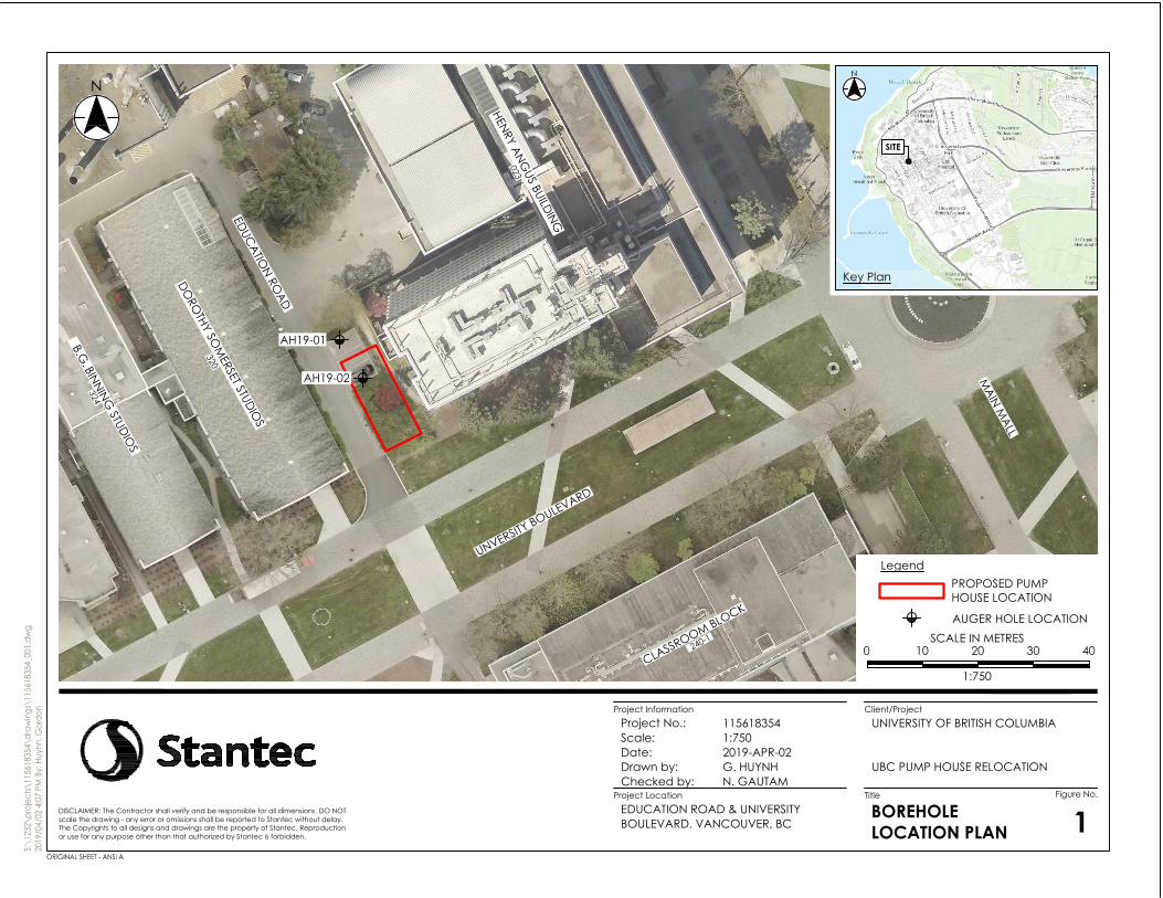
UBC previously identified a site that is approximately 150 square meters in size, bound by the Henry Angus Building to the east, University Boulevard to the south, Education Road to the west, and an unnamed access roadway to the north. The site is generally level with an approximate elevation of 91 m (Geodetic). The site was developed with landscaping features including a grass covered area, paved parking areas and shrubbery at the time of our geotechnical exploration work.
The Pump House will be located approximately 4 m west of the Henry Angus building, which is understood to have one level of below grade basement and foundations at a similar elevation to those proposed for the Pump House. Numerous utilities, including an existing storm line with an invert elevation between 2 and 2.7 m below existing grades are currently located within the proposed building footprint.
2.2 GEOLOGICAL SETTING Review of the Surficial Geology Map 1486A, Vancouver indicates that the surficial geology in the general area of the site is defined as Pleistocene – Vashon drift and Capilano Sediments that are locally comprised of lodgement and minor flow till, lenses and interbeds of substratified glaciofluvial sand to gravel, and lenses and interbeds of glaciolacustrine laminated stony silt up to 25 meters thick.
4/15/2019
pj u:\1156\115618354_ubc_pumphouse\05_report_delivery\fnl\rpt_ubc_pump_house_fnl_040919.docx 4.3
3.0 GEOTECHNICAL EXPLORATION
3.1 FIELD EXPLORATION
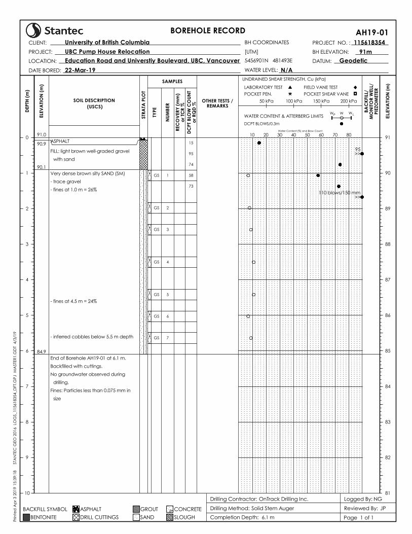
A geotechnical borehole exploration was carried out on March 22, 2019 and consisted of two (2) auger boreholes, AH19-01 and AH19-02. The boreholes were advanced to a depth of 6.1 m below the existing ground surface with the location of the boreholes are shown on Drawing No. 1 in Appendix B.
The boreholes were drilled using 140 mm diameter solid stem augers with a rubber track mounted drill rig operated by OnTrack Drilling Inc., Langley, British Columbia.
Dynamic Cone Penetration Tests (DCPTs) were carried out prior to and adjacent to each borehole. The purpose of the DCPT was to assess in-situ consistency or compactness of the existing soil layers. The DCPT includes advancing a 60-degree apex cone into the ground using a drop-hammer with a standardized drop height and weight of 760 mm and 63.5 kg, respectively. The hammer blows are counted during driving and the cumulative blows for each 300 mm of penetration is recorded as DCPT blow counts. The DCPT testing was carried out until practical equipment refusal, defined as minimum 100 blows per 300 mm of penetration. DCPT refusal was encountered within the very dense soils at approximately 1.8 and 2 m depth near boreholes AH19-01 and AH19-02, respectively. The DCPT blow counts are shown on the Borehole Records in Appendix B.
The geotechnical subsurface exploration was monitored by Stantec staff, who identified the sample locations, classified the soils in accordance with ASTM Standard D2488, kept detailed borehole logs, recorded DCPT blow counts, and observed and recorded pertinent site features. Representative soil samples from the boreholes were collected, placed in moisture-tight containers, and taken to our laboratory.
3.2 LABORATORY TESTING
The objectives of the laboratory testing program were to aid in the classification of soil samples and to derive engineering design parameters of the soils. The tests consisted of visual classification (ASTM D2487 and D2488), water content measurement (ASTM D2216), and fines content measurement (ASTM D1140 Method A). The results of the laboratory soil testing are shown on the Borehole Records provided in Appendix B.
4.0 SUBSURFACE CONDITIONS
4.1 SUBSURFACE SOIL CONDITIONS
The geotechnical site exploration shows that the soil conditions encountered at the Site are in general accordance with the published surficial geology information discussed in Section 2.2. The subsurface conditions encountered at the time of the site exploration generally consisted of asphalt pavement over fill,
4/15/2019
pj u:\1156\115618354_ubc_pumphouse\05_report_delivery\fnl\rpt_ubc_pump_house_fnl_040919.docx 5.4
overlying a native deposit of very dense silty sand that extended beyond the termination depths of the boreholes. These soil units are described in detail below and in the borehole records in Appendix C.
Asphalt
Asphalt pavement approximately 65 mm to 75 mm in thickness, was encountered at the surface of both boreholes drilled over the existing parking areas.
Fill Soils
The asphalt was underlain by fill consisting of grey well graded gravel with sand and varying amounts of silt. The fill soils extended to depths ranging from approximately 0.6 m to 0.9 m below the existing ground surface.
Top soil and sod is expected within the grass covered areas of the site.
Silty Sand (Till-Like)
Very dense silty Sand was encountered beneath the fill soils in both boreholes. The silty sand extended beyond the termination depths of both boreholes at 6.1 m. Measured fines content (silt and clay sized particles passing the 0.075 mm, #200 sieve) of the samples taken from the silty sand layer ranged from approximately 17% to 42%, while moisture content varied from 6% to 11%. Traces of gravel were present along the thickness of the deposit, while cobbles are inferred to be present below a depth of 5.5 m and 6 m in borehole AH19-01 and AH19-02, respectively.
4.2 GROUNDWATER CONDITIONS
Groundwater was not encountered in either of the borehole during drilling, however perched groundwater conditions could be encountered during the wetter months of the year overlying the relatively impervious dense ‘till-like’ soils.
Soil and groundwater conditions between the boreholes can vary from those described above. Also, groundwater level can vary depending on the time of the year and precipitation levels.
5.0 SEISMIC DESIGN PARAMETERS
We understand that the seismic design of the new pump station structure would be in accordance with the provisions of BCBC (2018), with ground motions having a probability of exceedance of 2% in 50 years (i.e., 2,475-year return period earthquake).
Site-specific seismic design parameters were obtained from the interactive website maintained by the Geological Survey of Canada (Natural Resources Canada, 2016) in accordance with the provisions of BCBC (2018). The parameters are in the form of 5% damped horizontal spectral response acceleration, Sa(T) where T is the period in seconds. The Sa(T) values are determined for very dense soil or soft bedrock, taken as the reference ground condition corresponding to Site Class “C”.
4/15/2019
pj u:\1156\115618354_ubc_pumphouse\05_report_delivery\fnl\rpt_ubc_pump_house_fnl_040919.docx 6.5
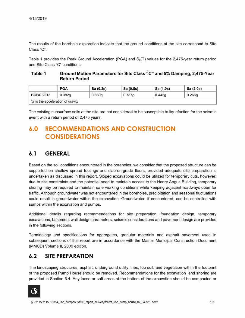
The results of the borehole exploration indicate that the ground conditions at the site correspond to Site Class “C”.
Table 1 provides the Peak Ground Acceleration (PGA) and Sa(T) values for the 2,475-year return period and Site Class “C” conditions.
Table 1 Ground Motion Parameters for Site Class “C” and 5% Damping, 2,475-Year Return Period
PGA Sa (0.2s) Sa (0.5s) Sa (1.0s) Sa (2.0s) BCBC 2018 0.382g 0.880g 0.787g 0.442g 0.266g
‘g’ is the acceleration of gravity
The existing subsurface soils at the site are not considered to be susceptible to liquefaction for the seismic event with a return period of 2,475 years.
6.0 RECOMMENDATIONS AND CONSTRUCTION CONSIDERATIONS
6.1 GENERAL
Based on the soil conditions encountered in the boreholes, we consider that the proposed structure can be supported on shallow spread footings and slab-on-grade floors, provided adequate site preparation is undertaken as discussed in this report. Sloped excavations could be utilized for temporary cuts, however, due to site constraints and the potential need to maintain access to the Henry Angus Building, temporary shoring may be required to maintain safe working conditions while keeping adjacent roadways open for traffic. Although groundwater was not encountered in the boreholes, precipitation and seasonal fluctuations could result in groundwater within the excavation. Groundwater, if encountered, can be controlled with sumps within the excavation and pumps.
Additional details regarding recommendations for site preparation, foundation design, temporary excavations, basement wall design parameters, seismic considerations and pavement design are provided in the following sections.
Terminology and specifications for aggregates, granular materials and asphalt pavement used in subsequent sections of this report are in accordance with the Master Municipal Construction Document (MMCD) Volume II, 2009 edition.
6.2 SITE PREPARATION
The landscaping structures, asphalt, underground utility lines, top soil, and vegetation within the footprint of the proposed Pump House should be removed. Recommendations for the excavation and shoring are provided in Section 6.4. Any loose or soft areas at the bottom of the excavation should be compacted or

4/15/2019
pj u:\1156\115618354_ubc_pumphouse\05_report_delivery\fnl\rpt_ubc_pump_house_fnl_040919.docx 6.6
sub-excavated and replaced with approved compacted structural fill as discussed later. If cobbles and boulders are encountered at the proposed footing elevations, sub-excavation may be required to remove them to avoid point loads in the foundations. All sub-excavated areas should be backfilled with structural fill to the underside of the footings as described in Section 6.3. The excavation and subgrade should be reviewed by the geotechnical engineer.
The excavated silty sands may be suitable as site grading fill if handled properly, protected from moisture, free of organics, debris and deleterious materials and if the soils can be placed and compacted to the required specifications. The native soils are moisture sensitive and would soften if saturated and/or disturbed and would be difficult to compact. On this basis, we recommend the earthworks be completed during extended periods of warm, dry weather.
6.3 STRUCTURAL FILL
Structural fill below foundations should consist of 75 mm (3 inch) minus Pit Run Gravel, Pit Run Sand or River Sand meeting the MMCD specifications, Section 31 05 17, Items 2.3, 2.4 and 2.5 respectively.
Excavated soils to be re-used as backfill should be stockpiled and reviewed by the geotechnical engineer to confirm suitability. All stockpiled fill should be covered with polyethylene sheeting to prevent moisture intrusion and to prevent runoff from the stockpile entering UBC’s storm sewer system. Structural fill should be placed in maximum 300 mm loose lifts and compacted to at least 95% of the Modified Proctor Maximum Dry Density (MPMDD).
6.4 EXCAVATIONS
All excavations should be carried out in accordance with Part 20 of the current WorkSafeBC regulations (WorkSafeBC, 2013) and be safe for worker entry. Sloped cut or shoring of the excavations would be required as the subsurface soils consist of silty sands and the excavation is expected to remain open for several days.
Excavated material should be stockpiled at a distance greater than the depth of the excavation, measured from the crest. Construction equipment and vehicles should be kept a minimum 2 m from the crest of all excavations.
The following sections provide recommendations for unsupported and supported temporary excavations less than 6 m deep (less than 6 m between the base of the excavation and the top of the adjacent ground).
6.4.1 Unsupported Excavations
Unsupported excavations should be cut at no steeper than 1.5H:1V (horizontal to vertical).
Excavation side slopes should be covered with polyethylene sheets secured to the ground with nails to protect the slope from precipitation and associated ground surface run-off. The slopes should be regularly reviewed by the geotechnical engineer for signs of instability. If groundwater seepage occurs through the sides of the excavation, the slopes may undergo sloughing, in which case additional maintenance and
4/15/2019
pj u:\1156\115618354_ubc_pumphouse\05_report_delivery\fnl\rpt_ubc_pump_house_fnl_040919.docx 6.7
monitoring would be necessary. If localized instability is noted during excavation, or if wet conditions are encountered, the side slopes should be flattened as required to maintain safe working conditions.
The Contractor should inspect excavations regularly for signs of instability, and slopes should be flattened if required.
6.4.2 Supported Excavations
Temporary excavation support measures might be utilized to maintain excavation stability, allow for safe worker entry into excavations, and minimize excavation volumes and lateral extents. Options of excavation support may include use of concrete lock-block walls along the inside perimeter for excavation less than 2.2 m deep, shotcrete and anchor walls or other alternatives. The excavation support should be continuous to prevent sloughing of soils.
Slumping of the excavation walls should be anticipated for excavations adjacent to existing utility trenches as trench backfill material including granular and/or poor-quality fills from previous construction may be present. We recommend voids between the temporary excavation support and the excavation cut faces, when observed, be filled with low-strength concrete (controlled density fill, CDF).
Design of the temporary shoring and drawings can be provided once the detailed design of the structure is completed and foundation drawings are available.
6.5 FOUNDATION DESIGN RECOMMENDATIONS
6.5.1 Bearing Resistance
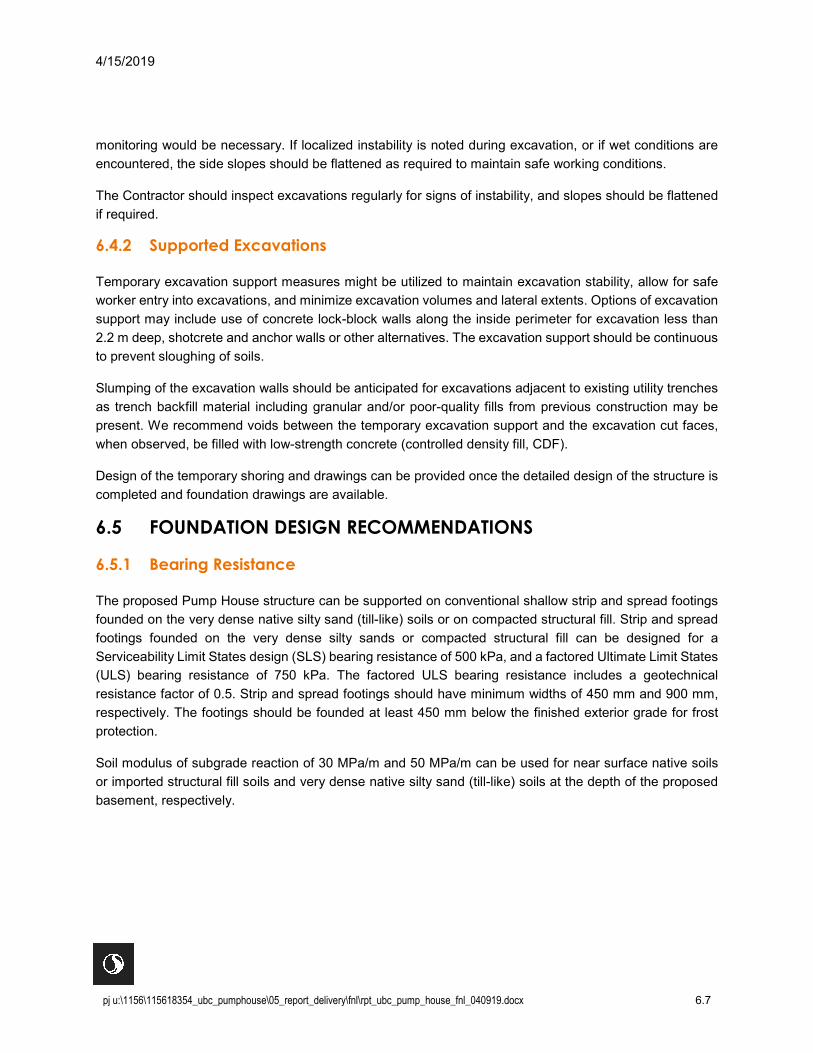
The proposed Pump House structure can be supported on conventional shallow strip and spread footings founded on the very dense native silty sand (till-like) soils or on compacted structural fill. Strip and spread footings founded on the very dense silty sands or compacted structural fill can be designed for a Serviceability Limit States design (SLS) bearing resistance of 500 kPa, and a factored Ultimate Limit States (ULS) bearing resistance of 750 kPa. The factored ULS bearing resistance includes a geotechnical resistance factor of 0.5. Strip and spread footings should have minimum widths of 450 mm and 900 mm, respectively. The footings should be founded at least 450 mm below the finished exterior grade for frost protection.
Soil modulus of subgrade reaction of 30 MPa/m and 50 MPa/m can be used for near surface native soils or imported structural fill soils and very dense native silty sand (till-like) soils at the depth of the proposed basement, respectively.
4/15/2019
pj u:\1156\115618354_ubc_pumphouse\05_report_delivery\fnl\rpt_ubc_pump_house_fnl_040919.docx 6.8
6.5.2 Settlement
Estimated total post-construction settlement of the foundations constructed as discussed above would be less than 25 mm under the SLS condition. Differential settlement between adjacent foundations is estimated to be less than12.5 mm.
6.6 SLAB-ON-GRADE
The basement floors of the proposed structure can be constructed as slab-on-grade. A minimum 150 mm thick drainage layer comprising 19 mm clean clear crushed gravel should be provided below the slab-on-grade. The subgrade should be reviewed by the geotechnical engineer prior to the placement and compaction of the 19 mm clear crushed layer. Following review of the compacted gravel drainage layer, it should be covered with 0.15 mm (6 mil) thick polyethylene sheets. This gravel drainage layer should be connected to the building perimeter drainage system as described in section 6.9.
6.7 LATERAL EARTH PRESSURES
Basement walls will be required along all sides of the proposed structure.
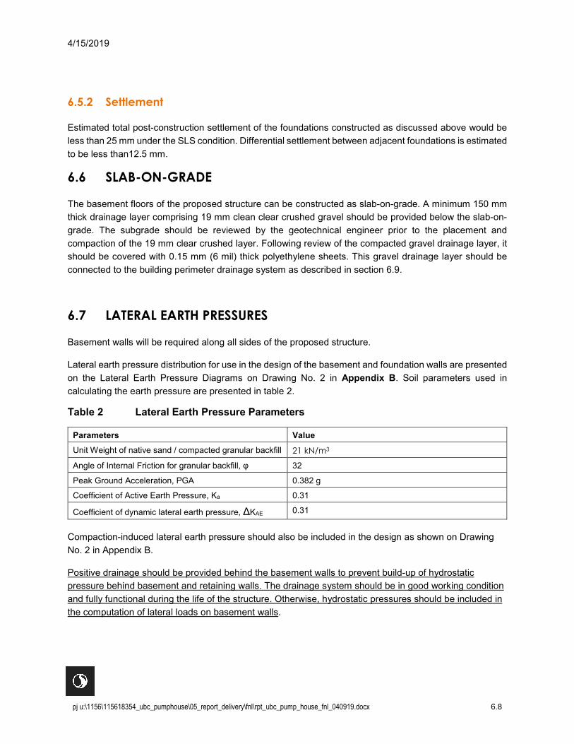
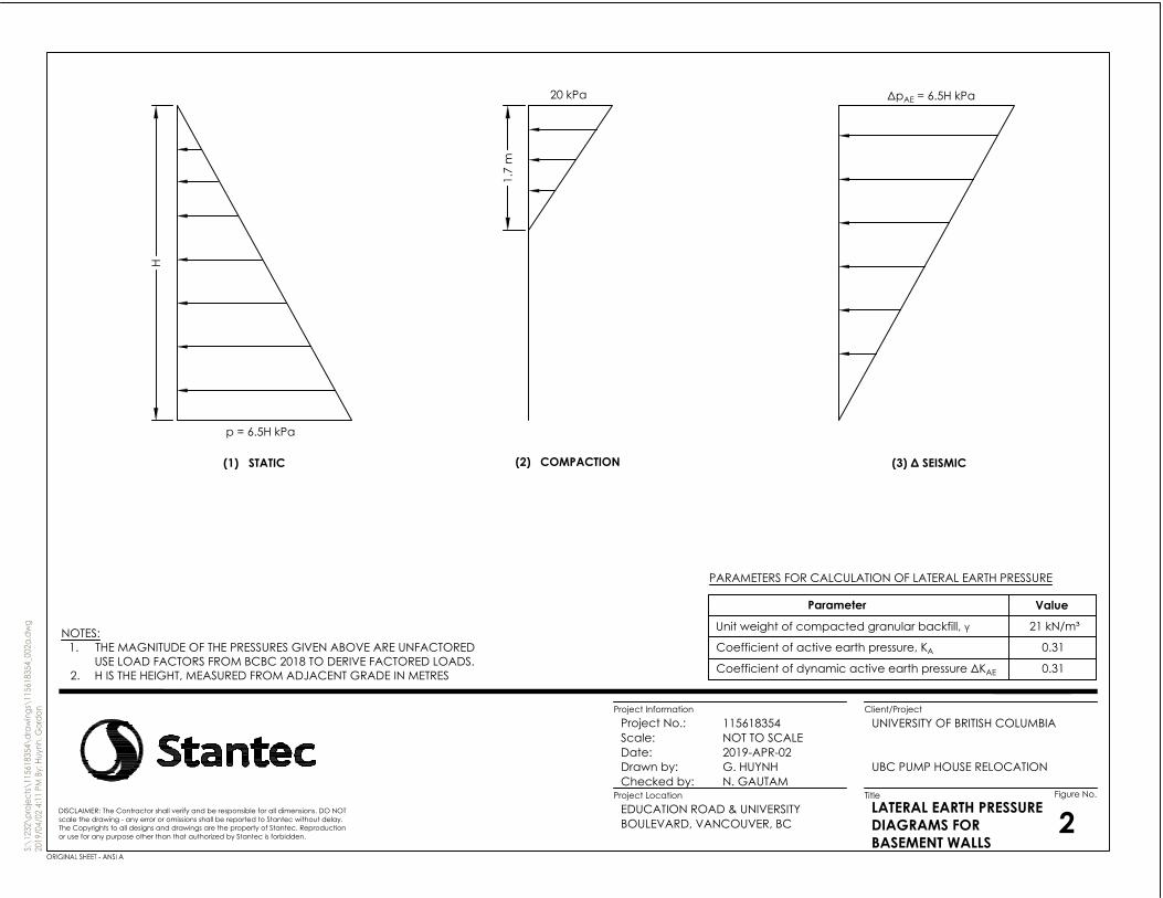
Lateral earth pressure distribution for use in the design of the basement and foundation walls are presented on the Lateral Earth Pressure Diagrams on Drawing No. 2 in Appendix B. Soil parameters used in calculating the earth pressure are presented in table 2.
Table 2 Lateral Earth Pressure Parameters
Parameters Value Unit Weight of native sand / compacted granular backfill 21 kN/m3
Angle of Internal Friction for granular backfill, φ 32
Peak Ground Acceleration, PGA 0.382 g
Coefficient of Active Earth Pressure, Ka 0.31
Coefficient of dynamic lateral earth pressure, ΔKAE 0.31
Compaction-induced lateral earth pressure should also be included in the design as shown on Drawing No. 2 in Appendix B.
Positive drainage should be provided behind the basement walls to prevent build-up of hydrostatic pressure behind basement and retaining walls. The drainage system should be in good working condition and fully functional during the life of the structure. Otherwise, hydrostatic pressures should be included in the computation of lateral loads on basement walls.

4/15/2019
pj u:\1156\115618354_ubc_pumphouse\05_report_delivery\fnl\rpt_ubc_pump_house_fnl_040919.docx 6.9
6.8 UTILITY TRENCHING AND BACKFILLING
Pipes and utilities installed using open cut trench excavation methods should be placed on a bedding layer having a thickness of at least 150 mm for pipe cushioning, we recommend that the granular bedding and surround material should extend at least 300 mm beyond both sides of the pipe and up to at least 150 mm above the top of the pipe.
Pipe bedding and surround materials should meet the MMCD requirements for imported granular bedding (MMCD, Section 31 05 1, Item 2.7). Alternatively, imported 25 mm clear crushed gravel (MMCD, Section 31 05 17, Item 2.6 – Coarse) can be used for pipe bedding and surround provided it is encapsulated in a non-woven geotextile to prevent migration of fines from adjacent fill and native soils. Non-woven geotextile with a tensile strength of 750 N and an “apparent opening size of 0.212 mm is recommended (Geotextile #4551 as supplied by Nilex or approved equivalent would meet these specifications).
The pipe bedding and surround material should be placed in maximum 150 mm loose lifts if hand-operated compaction equipment is used, and 300 mm thick loose lifts if heavy machine-operated equipment is used. The material must be compacted to 98% SPMDD.
Backfill above pipe bedding and surround zone should consist of Pit Run Gravel (MMCD Section 31 05 17, Item 2.3), or Pit Run Sand (MMCD Section 21 05 17, Item 2.4). Granular backfill materials should be compacted to at least 98% SPMDD.
A geotechnical engineer should review fill material, placement, lift thickness and compaction.
6.9 PERIMETER AND SITE DRAINAGE
Permanent drainage provisions should consist of perimeter drainage at the foundation level around all portions of structures and should include 150 mm diameter perforated rigid wall pipes. The drainage pipes should be surrounded by a minimum of 300 mm of 25 mm drain rock or 25 mm clear crush gravel (MMCD, Section 31 05 17, Item 2.6) encapsulated in filter fabric. The perforated pipe should be installed with perforations at 60 degrees off the base of the pipe. Perimeter drains should be provided with permanent clean-outs. Note that “Big O” type pipe is not considered to be suitable for building drainage purposes. Non-woven geotextile with a tensile strength of 750 N and “apparent opening size of 0.212 mm is recommended as filter fabric (Geotextile #4551 as supplied by Nilex or approved equivalent would meet these specifications).
The drainage pipes should be located at an elevation below the underside of the floor slab, sloped at a minimum 0.5% to 1% gradient and be connected to a pumped sump or to a suitable gravity outlet. A gravel drainage layer should also be provided under the floor slab as discussed previously and connected to the perimeter drainage system.
Weep holes should be provided along the perimeter wall to allow positive drainage from the underside of slab-on-grade to the perimeter drainage system. A weep hole spacing of 5 m is recommended. Areas which are below slab-on-grade, such as air ducts or mechanical pits should have similar drainage provisions unless the walls are waterproofed and designed for water pressure.
4/15/2019
pj u:\1156\115618354_ubc_pumphouse\05_report_delivery\fnl\rpt_ubc_pump_house_fnl_040919.docx 6.10
The roof and surface runoff should be collected and directed to storm sewer in a solid-wall pipe, separate from the perimeter drainage. Final ground surfaces around the structure should be graded to direct surface runoff away from building areas.
6.10 PAVEMENT DESIGN
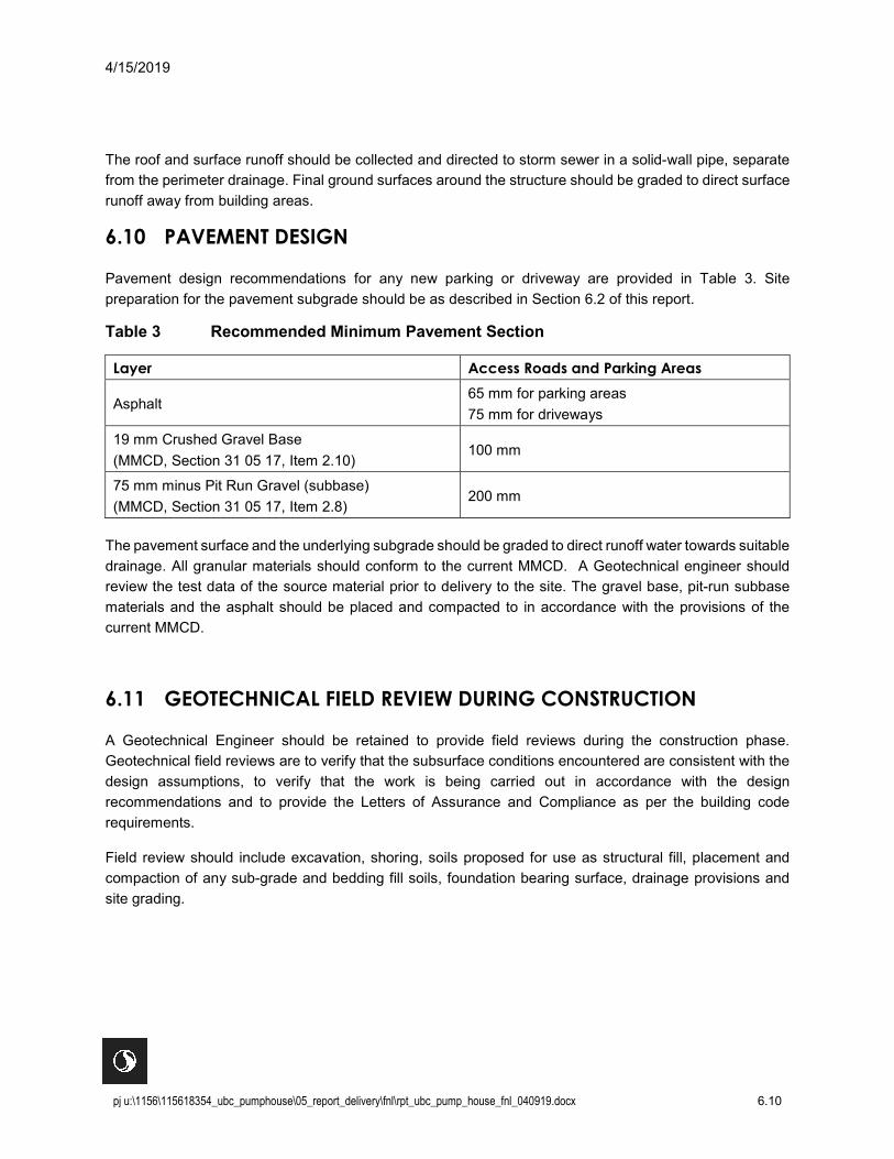
Pavement design recommendations for any new parking or driveway are provided in Table 3. Site preparation for the pavement subgrade should be as described in Section 6.2 of this report.
Table 3 Recommended Minimum Pavement Section
Layer Access Roads and Parking Areas
Asphalt 65 mm for parking areas 75 mm for driveways
19 mm Crushed Gravel Base (MMCD, Section 31 05 17, Item 2.10)
100 mm
75 mm minus Pit Run Gravel (subbase) (MMCD, Section 31 05 17, Item 2.8)
200 mm
The pavement surface and the underlying subgrade should be graded to direct runoff water towards suitable drainage. All granular materials should conform to the current MMCD. A Geotechnical engineer should review the test data of the source material prior to delivery to the site. The gravel base, pit-run subbase materials and the asphalt should be placed and compacted to in accordance with the provisions of the current MMCD.
6.11 GEOTECHNICAL FIELD REVIEW DURING CONSTRUCTION
A Geotechnical Engineer should be retained to provide field reviews during the construction phase. Geotechnical field reviews are to verify that the subsurface conditions encountered are consistent with the design assumptions, to verify that the work is being carried out in accordance with the design recommendations and to provide the Letters of Assurance and Compliance as per the building code requirements.
Field review should include excavation, shoring, soils proposed for use as structural fill, placement and compaction of any sub-grade and bedding fill soils, foundation bearing surface, drainage provisions and site grading.

APPENDICES

UBC PUMP HOUSE REPLACEMENT
Appendix A Statement of General Conditions April 15, 2019
A.1
Appendix A STATEMENT OF GENERAL CONDITIONS

STATEMENT OF GENERAL CONDITIONS
USE OF THIS REPORT: This report has been prepared for the sole benefit of the Client or its agent and may not be used by any third party without the express written consent of Stantec and the Client. Any use which a third party makes of this report is the responsibility of such third party.
BASIS OF THE REPORT: The information, opinions, and/or recommendations made in this report are in accordance with Stantec’s present understanding of the site specific project as described by the Client. The applicability of these is restricted to the site conditions encountered at the time of the investigation or study. If the proposed site specific project differs or is modified from what is described in this report or if the site conditions are altered, this report is no longer valid unless Stantec is requested by the Client to review and revise the report to reflect the differing or modified project specifics and/or the altered site conditions.
STANDARD OF CARE: Preparation of this report, and all associated work, was carried out in accordance with the normally accepted standard of care in the state or province of execution for the specific professional service provided to the Client. No other warranty is made.
INTERPRETATION OF SITE CONDITIONS: Soil, rock, or other material descriptions, and statements regarding their condition, made in this report are based on site conditions encountered by Stantec at the time of the work and at the specific testing and/or sampling locations. Classifications and statements of condition have been made in accordance with normally accepted practices which are judgmental in nature; no specific description should be considered exact, but rather reflective of the anticipated material behavior. Extrapolation of in situ conditions can only be made to some limited extent beyond the sampling or test points. The extent depends on variability of the soil, rock and groundwater conditions as influenced by geological processes, construction activity, and site use.
VARYING OR UNEXPECTED CONDITIONS: Should any site or subsurface conditions be encountered that are different from those described in this report or encountered at the test locations, Stantec must be notified immediately to assess if the varying or unexpected conditions are substantial and if reassessments of the report conclusions or recommendations are required. Stantec will not be responsible to any party for damages incurred as a result of failing to notify Stantec that differing site or sub-surface conditions are present upon becoming aware of such conditions.
PLANNING, DESIGN, OR CONSTRUCTION: Development or design plans and specifications should be reviewed by Stantec, sufficiently ahead of initiating the next project stage (property acquisition, tender, construction, etc.), to confirm that this report completely addresses the elaborated project specifics and that the contents of this report have been properly interpreted. Specialty quality assurance services (field observations and testing) during construction are a necessary part of the evaluation of sub-subsurface conditions and site preparation works. Site work relating to the recommendations included in this report should only be carried out in the presence of a qualified geotechnical engineer; Stantec cannot be responsible for site work carried out without being present.

UBC PUMP HOUSE REPLACEMENT
Appendix B Drawings April 15, 2019
B.2
Appendix B DRAWINGS
AH19-01
AH19-02
HENRY ANGUS BUILDING
UNVERSITY BOULEVARD
MAIN M
ALL
CLASSROOM BLOCK
DORO
THY SOM
ERSET STUDIOS
EDUCATIO
N ROAD
B.G.BINNING
STUDIOS
240-1
320
324
Legend
BOREHOLELOCATION PLAN 1DISCLAIMER: The Contractor shall verify and be responsible for all dimensions. DO NOT
scale the drawing - any error or omissions shall be reported to Stantec without delay.The Copyrights to all designs and drawings are the property of Stantec. Reproductionor use for any purpose other than that authorized by Stantec is forbidden.
S:\1
232\
proj
ects\
1156
1835
4\dr
awin
gs\1
1561
8354
_001
.dw
g20
19/0
4/02
4:0
7 PM B
y: Hu
ynh,
Gor
don
Title Figure No.
Client/ProjectProject Information
Scale:Project No.:
Date:
Checked by: Drawn by:
Project Location
1156183541:7502019-APR-02
N. GAUTAMG. HUYNH
EDUCATION ROAD & UNIVERSITY BOULEVARD, VANCOUVER, BC
UNIVERSITY OF BRITISH COLUMBIA
UBC PUMP HOUSE RELOCATION
ORIGINAL SHEET - ANSI A
N
0 10 3020
1:750
SCALE IN METRES40
AUGER HOLE LOCATION
PROPOSED PUMPHOUSE LOCATION
023
Key Plan
SITE
N
LATERAL EARTH PRESSUREDIAGRAMS FORBASEMENT WALLS
2DISCLAIMER: The Contractor shall verify and be responsible for all dimensions. DO NOTscale the drawing - any error or omissions shall be reported to Stantec without delay.The Copyrights to all designs and drawings are the property of Stantec. Reproductionor use for any purpose other than that authorized by Stantec is forbidden.
ORIGINAL SHEET - ANSI A
p = 6.5H kPa
20 kPa ΔpAE = 6.5H kPa
(1) STATIC (2) COMPACTION (3) Δ SEISMIC
H
1.7
m
PARAMETERS FOR CALCULATION OF LATERAL EARTH PRESSURE
Unit weight of compacted granular backfill, γ
Parameter
21 kN/m³
Value
Coefficient of active earth pressure, KA 0.31
Coefficient of dynamic active earth pressure ΔKAE 0.31
NOTES:1. THE MAGNITUDE OF THE PRESSURES GIVEN ABOVE ARE UNFACTORED
USE LOAD FACTORS FROM BCBC 2018 TO DERIVE FACTORED LOADS.2. H IS THE HEIGHT, MEASURED FROM ADJACENT GRADE IN METRES
S:\1
232\
proj
ects\
1156
1835
4\dr
awin
gs\1
1561
8354
_002
a.dw
g20
19/0
4/02
4:1
1 PM B
y: Hu
ynh,
Gor
don
Title Figure No.
Client/ProjectProject Information
Scale:Project No.:
Date:
Checked by: Drawn by:
Project Location
115618354NOT TO SCALE2019-APR-02
N. GAUTAMG. HUYNH
EDUCATION ROAD & UNIVERSITY BOULEVARD, VANCOUVER, BC
UNIVERSITY OF BRITISH COLUMBIA
UBC PUMP HOUSE RELOCATION

UBC PUMP HOUSE REPLACEMENT
Appendix C Borehole Records April 15, 2019
C.3
Appendix C BOREHOLE RECORDS
SYMBOLS AND TERMS USED ON BOREHOLE AND TEST PIT RECORDS – JULY 2014 Page 1 of 3
SYMBOLS AND TERMS USED ON BOREHOLE AND TEST PIT RECORDS
SOIL DESCRIPTION
Terminology describing common soil genesis:
Rootmat - vegetation, roots and moss with organic matter and topsoil typically forming a
mattress at the ground surface
Topsoil - mixture of soil and humus capable of supporting vegetative growth
Peat - mixture of visible and invisible fragments of decayed organic matter
Till - unstratified glacial deposit which may range from clay to boulders
Fill - material below the surface identified as placed by humans (excluding buried services)
Terminology describing soil structure:
Desiccated - having visible signs of weathering by oxidization of clay minerals, shrinkage cracks, etc.
Fissured - having cracks, and hence a blocky structure
Varved - composed of regular alternating layers of silt and clay
Stratified - composed of alternating successions of different soil types, e.g. silt and sand
Layer - > 75 mm in thickness
Seam - 2 mm to 75 mm in thickness
Parting - < 2 mm in thickness
Terminology describing soil types:
The classification of soil types are made on the basis of grain size and plasticity in accordance with the Unified
Soil Classification System (USCS) (ASTM D 2487 or D 2488) which excludes particles larger than 75 mm. For
particles larger than 75 mm, and for defining percent clay fraction in hydrometer results, definitions proposed by
Canadian Foundation Engineering Manual, 4th Edition are used. The USCS provides a group symbol (e.g. SM)
and group name (e.g. silty sand) for identification.
Terminology describing cobbles, boulders, and non-matrix materials (organic matter or debris):
Terminology describing materials outside the USCS, (e.g. particles larger than 75 mm, visible organic matter, and
construction debris) is based upon the proportion of these materials present:
Trace, or occasional Less than 10%
Some 10-20%
Frequent > 20%
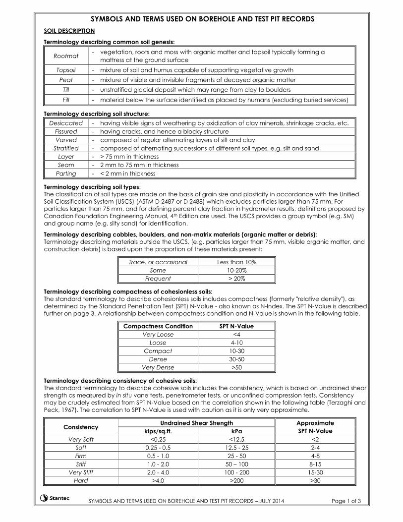
Terminology describing compactness of cohesionless soils:
The standard terminology to describe cohesionless soils includes compactness (formerly "relative density"), as
determined by the Standard Penetration Test (SPT) N-Value - also known as N-Index. The SPT N-Value is described
further on page 3. A relationship between compactness condition and N-Value is shown in the following table.
Compactness Condition SPT N-Value
Very Loose <4
Loose 4-10
Compact 10-30
Dense 30-50
Very Dense >50
Terminology describing consistency of cohesive soils:
The standard terminology to describe cohesive soils includes the consistency, which is based on undrained shear
strength as measured by in situ vane tests, penetrometer tests, or unconfined compression tests. Consistency
may be crudely estimated from SPT N-Value based on the correlation shown in the following table (Terzaghi and
Peck, 1967). The correlation to SPT N-Value is used with caution as it is only very approximate.
Consistency Undrained Shear Strength Approximate
SPT N-Value kips/sq.ft. kPa
Very Soft <0.25 <12.5 <2
Soft 0.25 - 0.5 12.5 - 25 2-4
Firm 0.5 - 1.0 25 - 50 4-8
Stiff 1.0 - 2.0 50 – 100 8-15
Very Stiff 2.0 - 4.0 100 - 200 15-30
Hard >4.0 >200 >30
SYMBOLS AND TERMS USED ON BOREHOLE AND TEST PIT RECORDS – JULY 2014 Page 2 of 3
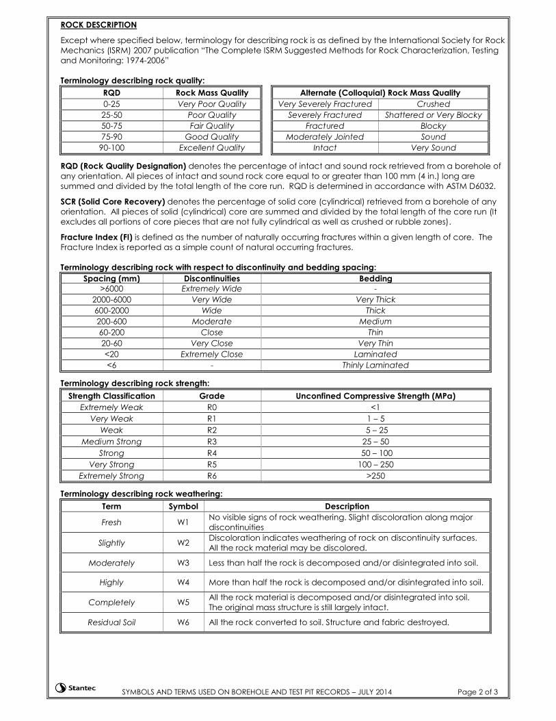
ROCK DESCRIPTION
Except where specified below, terminology for describing rock is as defined by the International Society for Rock
Mechanics (ISRM) 2007 publication “The Complete ISRM Suggested Methods for Rock Characterization, Testing
and Monitoring: 1974-2006”
Terminology describing rock quality:
RQD Rock Mass Quality Alternate (Colloquial) Rock Mass Quality
0-25 Very Poor Quality Very Severely Fractured Crushed
25-50 Poor Quality Severely Fractured Shattered or Very Blocky
50-75 Fair Quality Fractured Blocky
75-90 Good Quality Moderately Jointed Sound
90-100 Excellent Quality Intact Very Sound
RQD (Rock Quality Designation) denotes the percentage of intact and sound rock retrieved from a borehole of
any orientation. All pieces of intact and sound rock core equal to or greater than 100 mm (4 in.) long are
summed and divided by the total length of the core run. RQD is determined in accordance with ASTM D6032.
SCR (Solid Core Recovery) denotes the percentage of solid core (cylindrical) retrieved from a borehole of any
orientation. All pieces of solid (cylindrical) core are summed and divided by the total length of the core run (It
excludes all portions of core pieces that are not fully cylindrical as well as crushed or rubble zones).
Fracture Index (FI) is defined as the number of naturally occurring fractures within a given length of core. The
Fracture Index is reported as a simple count of natural occurring fractures.
Terminology describing rock with respect to discontinuity and bedding spacing:
Spacing (mm) Discontinuities Spacing
Bedding
>6000 Extremely Wide -
2000-6000 Very Wide Very Thick
600-2000 Wide Thick
200-600 Moderate Medium
60-200 Close Thin
20-60 Very Close Very Thin
<20 Extremely Close Laminated
<6 - Thinly Laminated
Terminology describing rock strength:
Strength Classification Grade Unconfined Compressive Strength (MPa)
Extremely Weak R0 <1
Very Weak R1 1 – 5
Weak R2 5 – 25
Medium Strong R3 25 – 50
Strong R4 50 – 100
Very Strong R5 100 – 250
Extremely Strong R6 >250
Terminology describing rock weathering:
Term Symbol Description
Fresh W1 No visible signs of rock weathering. Slight discoloration along major
discontinuities
Slightly W2 Discoloration indicates weathering of rock on discontinuity surfaces.
All the rock material may be discolored.
Moderately W3 Less than half the rock is decomposed and/or disintegrated into soil.
Highly W4 More than half the rock is decomposed and/or disintegrated into soil.
Completely W5 All the rock material is decomposed and/or disintegrated into soil.
The original mass structure is still largely intact.
Residual Soil W6 All the rock converted to soil. Structure and fabric destroyed.
SYMBOLS AND TERMS USED ON BOREHOLE AND TEST PIT RECORDS – JULY 2014 Page 3 of 3
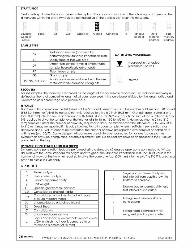
STRATA PLOT
Strata plots symbolize the soil or bedrock description. They are combinations of the following basic symbols. The
dimensions within the strata symbols are not indicative of the particle size, layer thickness, etc.
Boulders
Cobbles
Gravel
Sand Silt Clay Organics Asphalt Concrete Fill Igneous
Bedrock
Meta-
morphic
Bedrock
Sedi-
mentary
Bedrock
SAMPLE TYPE
SS Split spoon sample (obtained by
performing the Standard Penetration Test)
ST Shelby tube or thin wall tube
DP Direct-Push sample (small diameter tube
sampler hydraulically advanced)
PT Piston tube sample
GS Grab sample
HQ, NQ, BQ, etc. Rock core samples obtained with the use
of standard size diamond coring bits.
RECOVERY
For soil samples, the recovery is recorded as the length of the soil sample recovered. For rock core, recovery is
defined as the total cumulative length of all core recovered in the core barrel divided by the length drilled and
is recorded as a percentage on a per run basis.
N-VALUE
Numbers in this column are the field results of the Standard Penetration Test: the number of blows of a 140 pound
(63.5 kg) hammer falling 30 inches (760 mm), required to drive a 2 inch (50.8 mm) O.D. split spoon sampler one
foot (300 mm) into the soil. In accordance with ASTM D1586, the N-Value equals the sum of the number of blows
(N) required to drive the sampler over the interval of 6 to 18 in. (150 to 450 mm). However, when a 24 in. (610
mm) sampler is used, the number of blows (N) required to drive the sampler over the interval of 12 to 24 in. (300
to 610 mm) may be reported if this value is lower. For split spoon samples where insufficient penetration was
achieved and N-Values cannot be presented, the number of blows are reported over sampler penetration in
millimetres (e.g. 50/75). Some design methods make use of N-values corrected for various factors such as
overburden pressure, energy ratio, borehole diameter, etc. No corrections have been applied to the N-values
presented on the log.
DYNAMIC CONE PENETRATION TEST (DCPT)
Dynamic cone penetration tests are performed using a standard 60 degree apex cone connected to ‘A’ size
drill rods with the same standard fall height and weight as the Standard Penetration Test. The DCPT value is the
number of blows of the hammer required to drive the cone one foot (300 mm) into the soil. The DCPT is used as a
probe to assess soil variability.
OTHER TESTS
S Sieve analysis
H Hydrometer analysis
k Laboratory permeability
γ Unit weight
Gs Specific gravity of soil particles
CD Consolidated drained triaxial
CU Consolidated undrained triaxial with pore
pressure measurements
UU Unconsolidated undrained triaxial
DS Direct Shear
C Consolidation
Qu Unconfined compression
Ip
Point Load Index (Ip on Borehole Record equals
Ip(50) in which the index is corrected to a
reference diameter of 50 mm)
WATER LEVEL MEASUREMENT
measured in standpipe,
piezometer, or well
inferred
Single packer permeability test;
test interval from depth shown to
bottom of borehole
Double packer permeability test;
test interval as indicated
Falling head permeability test
using casing
Falling head permeability test
using well point or piezometer
90.9
90.1
84.9
GS
GS
GS
GS
GS
GS
GS
ASPHALT
FILL: light brown well-graded gravel
with sand
Very dense brown silty SAND (SM)
- trace gravel
- fines at 1.0 m = 26%
- fines at 4.5 m = 24%
- inferred cobbles below 5.5 m depth
End of Borehole AH19-01 at 6.1 m.
Backfilled with cuttings.
No groundwater observed during
drilling.
Fines: Particles less than 0.075 mm in
size
1
2
3
4
5
6
7
15
95
74
58
73
91.0
BAC
KFI
LL/
MO
NIT
OR
WEL
L/PI
EZO
MET
ER
UNDRAINED SHEAR STRENGTH, Cu (kPa)
POCKET SHEAR VANE
91
90
89
88
87
86
85
84
83
82
81
DEP
TH (
m)
SAMPLES
(USCS)
EL
EV
AT
ION
(m
)
REC
OV
ERY
(m
m)
or T
CR
%
NU
MBE
R
50 kPa 100 kPa 150 kPa 200 kPa
0
1
2
3
4
5
6
7
8
9
10
10 20 30 40 50 60 70 80
ELEV
ATI
ON
(m
)
LABORATORY TEST
POCKET PEN.
WATER CONTENT & ATTERBERG LIMITSWP W W L
SOIL DESCRIPTION
TYPE
STRA
TA P
LOT
OTHER TESTS /REMARKS
FIELD VANE TEST
Water Content (%) and Blow CountDC
PT B
LOW
CO
UN
To
r RQ
D %
DCPT BLOWS/0.3m
CLIENT:
PROJECT:
LOCATION: Education Road and Universtiy Boulevard, UBC, Vancouver
University of British Columbia
UBC Pump House Relocation
22-Mar-19
5456901N 481493E
[UTM]
PROJECT NO. : 115618354
DATUM:
91m Geodetic
AH19-01
WATER LEVEL: N/A
BH COORDINATES
BH ELEVATION:
DATE BORED:
BOREHOLE RECORD
STA
NTE
C G
EO 2
016
LO
GS_
1156
1835
4_D
FT.G
PJ
MA
STER
1.G
DT
4/3
/19
BACKFILL SYMBOL
BENTONITE SAND SLOUGH
OnTrack Drilling Inc.
Completion Depth: 6.1 m
ASPHALT GROUT Solid Stem Auger
Prin
ted
Ap
r 3
2019
15:
39:1
8
Drilling Method:
DRILL CUTTINGS
Drilling Contractor:
Page of
NG
Reviewed By: JP
1 1
Logged By:
CONCRETE
>>95
>>110 blows/150 mm

90.9
90.2
84.9
GS
GS
GS
GS
GS
GS
GS
ASPHALT
FILL: light brown well-graded gravel
with sand
Very dense brown silty SAND (SM)
- trace gravel
- fines at 1.3 m = 42%
- fines at 4.2 m = 17%
- inferred cobbles below 6 m depth
End of Borehole AH19-02 at 6.1 m.
Backfilled with cuttings.
No groundwater observed during
drilling.
Fines: Particles less than 0.075 mm in
size
1
2
3
4
5
6
7
16
73
61
51
68
77
91.0
BAC
KFI
LL/
MO
NIT
OR
WEL
L/PI
EZO
MET
ER
UNDRAINED SHEAR STRENGTH, Cu (kPa)
POCKET SHEAR VANE
91
90
89
88
87
86
85
84
83
82
81
DEP
TH (
m)
SAMPLES
(USCS)
EL
EV
AT
ION
(m
)
REC
OV
ERY
(m
m)
or T
CR
%
NU
MBE
R
50 kPa 100 kPa 150 kPa 200 kPa
0
1
2
3
4
5
6
7
8
9
10
10 20 30 40 50 60 70 80
ELEV
ATI
ON
(m
)
LABORATORY TEST
POCKET PEN.
WATER CONTENT & ATTERBERG LIMITSWP W W L
SOIL DESCRIPTION
TYPE
STRA
TA P
LOT
OTHER TESTS /REMARKS
FIELD VANE TEST
Water Content (%) and Blow CountDC
PT B
LOW
CO
UN
To
r RQ
D %
DCPT BLOWS/0.3m
CLIENT:
PROJECT:
LOCATION: Education Road and Universtiy Boulevard, UBC, Vancouver
University of British Columbia
UBC Pump House Relocation
22-Mar-19
5456896N 481493E
[UTM]
PROJECT NO. : 115618354
DATUM:
91m Geodetic
AH19-02
WATER LEVEL: N/A
BH COORDINATES
BH ELEVATION:
DATE BORED:
BOREHOLE RECORD
STA
NTE
C G
EO 2
016
LO
GS_
1156
1835
4_D
FT.G
PJ
MA
STER
1.G
DT
4/3
/19
BACKFILL SYMBOL
BENTONITE SAND SLOUGH
OnTrack Drilling Inc.
Completion Depth: 6.1 m
ASPHALT GROUT Solid Stem Auger
Prin
ted
Ap
r 3
2019
15:
39:1
9
Drilling Method:
DRILL CUTTINGS
Drilling Contractor:
Page of
NG
Reviewed By: JP
1 1
Logged By:
CONCRETE
>>100 blows/200 mm