UAS TOPOGRAPHIC MAPPING WITH VELODYNE LiDAR … · * Corresponding author UAS TOPOGRAPHIC MAPPING...
8
___________________________________ * Corresponding author UAS TOPOGRAPHIC MAPPING WITH VELODYNE LiDAR SENSOR G. Jozkow a,b, *, C. Toth a , D. Grejner-Brzezinska a a Department of Civil, Environmental and Geodetic Engineering, The Ohio State University, 470 Hitchcock Hall, 2070 Neil Ave., Columbus, OH 43210, USA - (jozkow.1, toth.2, grejner-brzezinska.1)@osu.edu b Institute of Geodesy and Geoinformatics, Wroclaw University of Environmental and Life Sciences, Grunwaldzka 53, 50-357 Wroclaw, Poland - [email protected] Commission I, ICWG I/Vb KEY WORDS: UAS, UAV, LiDAR, mapping, performance analysis ABSTRACT: Unmanned Aerial System (UAS) technology is nowadays willingly used in small area topographic mapping due to low costs and good quality of derived products. Since cameras typically used with UAS have some limitations, e.g. cannot penetrate the vegetation, LiDAR sensors are increasingly getting attention in UAS mapping. Sensor developments reached the point when their costs and size suit the UAS platform, though, LiDAR UAS is still an emerging technology. One issue related to using LiDAR sensors on UAS is the limited performance of the navigation sensors used on UAS platforms. Therefore, various hardware and software solutions are investigated to increase the quality of UAS LiDAR point clouds. This work analyses several aspects of the UAS LiDAR point cloud generation performance based on UAS flights conducted with the Velodyne laser scanner and cameras. The attention was primarily paid to the trajectory reconstruction performance that is essential for accurate point cloud georeferencing. Since the navigation sensors, especially Inertial Measurement Units (IMUs), may not be of sufficient performance, the estimated camera poses could allow to increase the robustness of the estimated trajectory, and subsequently, the accuracy of the point cloud. The accuracy of the final UAS LiDAR point cloud was evaluated on the basis of the generated DSM, including comparison with point clouds obtained from dense image matching. The results showed the need for more investigation on MEMS IMU sensors used for UAS trajectory reconstruction. The accuracy of the UAS LiDAR point cloud, though lower than for point cloud obtained from images, may be still sufficient for certain mapping applications where the optical imagery is not useful. 1. INTRODUCTION Unmanned Aerial Systems (UASs) are getting recently more interest in the mapping community. They are offering similar products as traditional (manned) airborne systems but at lower costs. The current practice of UAS mapping is based on the imagery data that is indirectly georeferenced using Ground Control Points (GCPs). However, some applications need active sensors (e.g. LiDAR) that require direct georeferencing approach using navigation sensor data. The navigation sensors, such as Global Navigation Satellite System (GNSS) receivers and Inertial Measurement Units (IMUs) that are used for controlling and navigating typical Unmanned Aerial Vehicles (UAVs) are of lower performance and are not able to provide enough accurate georeferencing data. High grade IMUs might be used only for large UAS (Yang and Chen, 2015) what significantly increases system weight and costs. In the case of small UAS (sUAS), typically low grade micro-electro-mechanical systems (MEMS)–based IMUs are suitable and are frequently used for navigating and stabilizing the UAS platform. MEMS technology allowed for the significant reduction of the cost, weight, size, and power requirements of IMU sensors, but at the price of the performance, since such IMUs are characterized by large bias and noise (El-Sheimy, 2009). With strong developments in MEMS sensor technology, the newest IMUs are approaching the tactical grade performance, which is the dominant grade in typical aerial mapping systems. Some works have already proved that MEMS IMU might support UAS mapping (Hirose et al., 2015; Tulldahl and Larsson, 2014). In the case of GNSS receivers and antennas, UAS platforms are usually equipped with single-frequency Global Navigation System (GPS) receivers which are of sufficient performance for navigating the platform, but not for mapping purposes. However, a high (geodetic) grade miniaturized multi GNSS receivers are already available on the market at a reasonable price, and can be easily carried on even by the sUAS. These receivers very often support Real Time Kinematic (RTK) positioning that can be potentially used in real time applications. However, the drawback of the RTK is that it requires stable data linkage (e.g. through radio modem) and the computed position cannot be improved in post-processing since the raw observations are unavailable. The variety of the LiDAR sensors that are suitable for UAS is also growing. The first scanners used for that purpose, e.g. SICK LMS-291 were of relatively low performance, and their weight required the use of very heavy platforms (Nagai et al., 2009). The improvement in the LiDAR technology resulted in the reduction of weight and thus light-weight sensors, such as the ibeo LUX and SICK LD-MRS-400001 (Line et al. 2011; Wallace et al., 2012), and ultra-light weight (0.2 kg) Hokuyo UTM-30LX scanner (Kuhnert and Kuhnert, 2013; Roca et al., 2014; Hirose et al., 2015) were used on UAS platforms. However, these sensors were still of low performance. The first high performance laser scanner dedicated for UASs is the Riegl UAVX-1UAV (Amon et al., 2015; Mandlburger et al., 2015). In ISPRS Annals of the Photogrammetry, Remote Sensing and Spatial Information Sciences, Volume III-1, 2016 XXIII ISPRS Congress, 12–19 July 2016, Prague, Czech Republic This contribution has been peer-reviewed. The double-blind peer-review was conducted on the basis of the full paper. doi:10.5194/isprsannals-III-1-201-2016 201
Transcript of UAS TOPOGRAPHIC MAPPING WITH VELODYNE LiDAR … · * Corresponding author UAS TOPOGRAPHIC MAPPING...
___________________________________
* Corresponding author
UAS TOPOGRAPHIC MAPPING WITH VELODYNE LiDAR SENSOR
G. Jozkowa,b,*, C. Totha, D. Grejner-Brzezinskaa
a Department of Civil, Environmental and Geodetic Engineering, The Ohio State University, 470 Hitchcock Hall, 2070 Neil Ave.,
Columbus, OH 43210, USA - (jozkow.1, toth.2, grejner-brzezinska.1)@osu.edu b Institute of Geodesy and Geoinformatics, Wroclaw University of Environmental and Life Sciences, Grunwaldzka 53, 50-357
Wroclaw, Poland - [email protected]
Commission I, ICWG I/Vb
KEY WORDS: UAS, UAV, LiDAR, mapping, performance analysis
ABSTRACT:
Unmanned Aerial System (UAS) technology is nowadays willingly used in small area topographic mapping due to low costs and
good quality of derived products. Since cameras typically used with UAS have some limitations, e.g. cannot penetrate the vegetation,
LiDAR sensors are increasingly getting attention in UAS mapping. Sensor developments reached the point when their costs and size
suit the UAS platform, though, LiDAR UAS is still an emerging technology. One issue related to using LiDAR sensors on UAS is
the limited performance of the navigation sensors used on UAS platforms. Therefore, various hardware and software solutions are
investigated to increase the quality of UAS LiDAR point clouds. This work analyses several aspects of the UAS LiDAR point cloud
generation performance based on UAS flights conducted with the Velodyne laser scanner and cameras. The attention was primarily
paid to the trajectory reconstruction performance that is essential for accurate point cloud georeferencing. Since the navigation
sensors, especially Inertial Measurement Units (IMUs), may not be of sufficient performance, the estimated camera poses could
allow to increase the robustness of the estimated trajectory, and subsequently, the accuracy of the point cloud. The accuracy of the
final UAS LiDAR point cloud was evaluated on the basis of the generated DSM, including comparison with point clouds obtained
from dense image matching. The results showed the need for more investigation on MEMS IMU sensors used for UAS trajectory
reconstruction. The accuracy of the UAS LiDAR point cloud, though lower than for point cloud obtained from images, may be still
sufficient for certain mapping applications where the optical imagery is not useful.
1. INTRODUCTION
Unmanned Aerial Systems (UASs) are getting recently more
interest in the mapping community. They are offering similar
products as traditional (manned) airborne systems but at lower
costs. The current practice of UAS mapping is based on the
imagery data that is indirectly georeferenced using Ground
Control Points (GCPs). However, some applications need active
sensors (e.g. LiDAR) that require direct georeferencing
approach using navigation sensor data.
The navigation sensors, such as Global Navigation Satellite
System (GNSS) receivers and Inertial Measurement Units
(IMUs) that are used for controlling and navigating typical
Unmanned Aerial Vehicles (UAVs) are of lower performance
and are not able to provide enough accurate georeferencing
data. High grade IMUs might be used only for large UAS (Yang
and Chen, 2015) what significantly increases system weight and
costs. In the case of small UAS (sUAS), typically low grade
micro-electro-mechanical systems (MEMS)–based IMUs are
suitable and are frequently used for navigating and stabilizing
the UAS platform. MEMS technology allowed for the
significant reduction of the cost, weight, size, and power
requirements of IMU sensors, but at the price of the
performance, since such IMUs are characterized by large bias
and noise (El-Sheimy, 2009). With strong developments in
MEMS sensor technology, the newest IMUs are approaching
the tactical grade performance, which is the dominant grade in
typical aerial mapping systems. Some works have already
proved that MEMS IMU might support UAS mapping (Hirose
et al., 2015; Tulldahl and Larsson, 2014).
In the case of GNSS receivers and antennas, UAS platforms are
usually equipped with single-frequency Global Navigation
System (GPS) receivers which are of sufficient performance for
navigating the platform, but not for mapping purposes.
However, a high (geodetic) grade miniaturized multi GNSS
receivers are already available on the market at a reasonable
price, and can be easily carried on even by the sUAS. These
receivers very often support Real Time Kinematic (RTK)
positioning that can be potentially used in real time applications.
However, the drawback of the RTK is that it requires stable data
linkage (e.g. through radio modem) and the computed position
cannot be improved in post-processing since the raw
observations are unavailable.
The variety of the LiDAR sensors that are suitable for UAS is
also growing. The first scanners used for that purpose, e.g.
SICK LMS-291 were of relatively low performance, and their
weight required the use of very heavy platforms (Nagai et al.,
2009). The improvement in the LiDAR technology resulted in
the reduction of weight and thus light-weight sensors, such as
the ibeo LUX and SICK LD-MRS-400001 (Line et al. 2011;
Wallace et al., 2012), and ultra-light weight (0.2 kg) Hokuyo
UTM-30LX scanner (Kuhnert and Kuhnert, 2013; Roca et al.,
2014; Hirose et al., 2015) were used on UAS platforms.
However, these sensors were still of low performance. The first
high performance laser scanner dedicated for UASs is the Riegl
UAVX-1UAV (Amon et al., 2015; Mandlburger et al., 2015). In
ISPRS Annals of the Photogrammetry, Remote Sensing and Spatial Information Sciences, Volume III-1, 2016 XXIII ISPRS Congress, 12–19 July 2016, Prague, Czech Republic
This contribution has been peer-reviewed. The double-blind peer-review was conducted on the basis of the full paper. doi:10.5194/isprsannals-III-1-201-2016
201

contrast to other UAS scanners, the Riegl UAVX-1UAV is
characterized by very long range measurements (up to 920 m).
The good performance, however, comes with larger weight (3.6
kg) that limits the use of this sensor only to larger platforms.
Due to the use of multiple laser diodes (channels) inside a single
LiDAR sensor, Velodyne scanners are gaining attention in UAS
mapping, in particular the Velodyne HDL-32E (Tulldahl and
Larsson, 2014; Zhe et al., 2015) and the new Velodyne VLP-16.
Although the range of these sensors is not very high, the data
acquisition rate, low weight and price make these scanners very
attractive to use in UAS topographic mapping.
This work investigates the performance of a UAS equipped with
Velodyne laser scanner, where the platform direct
georeferencing is based on the MEMS IMU and dual-frequency
miniaturized GPS receiver data. The optical imagery obtained
by the same platform is used for comparison purposes and to
support alternative approaches of the platform georeferencing.
2. MATERIALS
2.1 Test UAS
The platform used in this study is the multipurpose Bergen
octocopter equipped with variety of navigation sensors (Figure
1), including:
1. NovAtel OEM615 dual-frequency GPS receiver and
Antcom antenna
2. Garmin GPS-18LV single-frequency GPS receiver
and antenna for time tagging the Velodye LiDAR data
3. Solmeta Geotagger N3 single-frequency GPS receiver
and antenna for position tagging of Nikon camera
images
4. Wookong-M autopilot systems consisting of single-
frequency GPS receiver and antenna, MEMS IMU,
and magnetometer; used only for navigating and
controlling octocopter flight
5. MicroStrain 3DM-GX3-35 consisting of single-
frequency GPS receiver and antenna, MEMS IMU,
and magnetometer; GPS sensor was used only for
time tagging IMU data; magnetometer data was not
used in this study
6. Epson M-G362PDC1 MEMS IMU
Figure 1. Navigation sensors mounted on the Bergen octocopter
The platform was also equipped with Gigabyte GB-BXi7 4500
small computer for recording data obtained from the Velodyne
laser scanner, NovAtel GPS receiver, and MicroStrain and
Epson IMUs. Besides collecting GPS raw observations, the
NovAtel receiver was also used for time tagging Epson IMU
data, and recording GPS time stamps for Nikon camera images.
The two MEMS IMUs mentioned above are approaching the
tactical grade performance level (Table 1) that should result in
the data of sufficient accuracy for the integration with the GPS
data acquired by the NovAtel receiver, and subsequently, for
direct georeferencing. The two IMUs were used for comparison
purposes. Note that according to the specification (Table 1)
Epson IMU has better gyros (lower value of gyro bias stability)
and slightly worse accelerometers than the MicroStrain IMU.
IMU Epson
M-G362PDC1
MicroStrain
3DM-GX3-35
Gyros
Measurement range [°/s] ±150 ±300
In-run bias stability [°/h] 3 18
Initial bias error [°/s] ±0.5 ±0.25
Noise density [°/s/Hz1/2] 0.002 0.03
Accelerometers
Measurement range [g] ±3 ±5
In-run bias stability [mg] <0.1 0.04
Initial bias error [mg] ±8 ±2
Noise density [mg/Hz1/2] 0.1 0.08
Other
Power consumption [mA] 30 200
Net weight [gram] 7 23
Table 1. Parameters of used IMU sensors
Since the used Bergen octocopter is a multipurpose platform, it
can support variety of mapping sensors. In this study, four
sensors are investigated, including:
1. Velodyne HDL-32E profile laser scanner
2. Velodyne VLP-16 profile laser scanner
3. Nikon D800 camera with Nikon a Nikkor AF-S 50
mm f/1.4G lens
4. GoPro Hero 3+ Black Edition camera with non-stock
5.4 mm lens
Velodyne laser scanner HDL-32E VLP-16
Appearance
Channels 32 16
Max. operation range [m] 100 100
Accuracy [cm] ±2 ±3
Dual returns yes yes
Horizontal field of view [°] 360 360
Horizontal resolution [°]
@ rotation rate [Hz]
0.08 @ 5
0.16 @ 10
0.35 @ 20
0.1 @ 5
0.2 @ 10
0.4 @ 20
Vertical field of view [°] -30.67 to +10.67 -15 to +15
Vertical resolution [°] 1.3 2.0
Measurement rate [pts/s] ~700,000 ~300,000
Power consumption [W] 12 8
Net weight [kg] 1 0.8
Table 2. Parameters of two Velodyne sensors
Tables 2 and 3 list the parameters of investigated LiDAR and
imagery sensors, respectively. The performance of both LiDAR
ISPRS Annals of the Photogrammetry, Remote Sensing and Spatial Information Sciences, Volume III-1, 2016 XXIII ISPRS Congress, 12–19 July 2016, Prague, Czech Republic
This contribution has been peer-reviewed. The double-blind peer-review was conducted on the basis of the full paper. doi:10.5194/isprsannals-III-1-201-2016
202
sensors is similar, however the HDL-32E can acquire more data
resulting in higher density, but VLP-16 is less heavy and does
not contain outer moving parts.
Camera Nikon GoPro
Appearance
Sensor width @ height [mm] 35.9 @ 24.0 6.2 @ 4.65a)
Image width @ height [pix] 7360 @ 4912 4000 @ 3000
Pixel size [m] ~4.88 1.55
Focal length [mm] 50 5.4
Horizontal field of view [°] 39 60
Weight [kg] 1.3 0.076 a) calculated from pixel and image size
Table 3. Parameters of the used cameras
Obviously, the payload of the used platform is limited and the
octocopter cannot be equipped with all aforementioned sensors
at the same time. However, besides the flight with one sensor at
a time, the size and weight of the Velodyne VLP-16 and GoPro
camera allow to mount them simultaneously and perform the
flight. Note that the used UAS in the heaviest configuration did
not exceed 13 kg of the total takeoff weight (platform, sensors,
power supply, etc.). The span of the Bergen octocopter is 1 m.
2.2 Test Flights
Test flights were executed in a waypoint based mode over
relatively flat terrain containing moderate complexity of non-
ground objects. Although the plan (Figure 2) was identical for
all flights, the actual flight trajectories may differ due to lower
performance of the navigation sensors included in the autopilot
system. Table 4 lists parameters that are common for all flights,
and nominal parameters specific for each mapping sensor.
Common parameters
Flying altitude AGL [m] 25
Flying speed [m/s] 4
Number of strips 3
Length of the strip [m] 73.72
Distance between strips [m] 12.57
NovAtel data acquisition rate [Hz] 5
Minimum IMU data acquisition rate [Hz] 100
Parameters for
Nikon / GoPro flights
Image acquisition rate [Hz] 1 / 2
GSD at nadir [mm] 12 / 2.5
Footprint width [m] 17.95 / 28.70
Footprint height [m] 12.00 / 21.53
Image endlap [%] 67 / 93
Image sidelap [%] 30 / 56
Parameters for Velodyne
HDL-32E / VLP-16 flights
Rotation rate [Hz] 10
Across flight FOV [°] 60
Swath width [m] 28.87
Strip overlap [%] 56
Average point spacing across flight a) [m] 0.08 / 0.10
Average point spacing along flight a) [m] 0.4
Along flight overlap [%] 98 / 97
Nominal average point density [pts/m2] 1,039 / 416 a) for single 0° channel
Table 4. Parameters of the flight and data acquisition
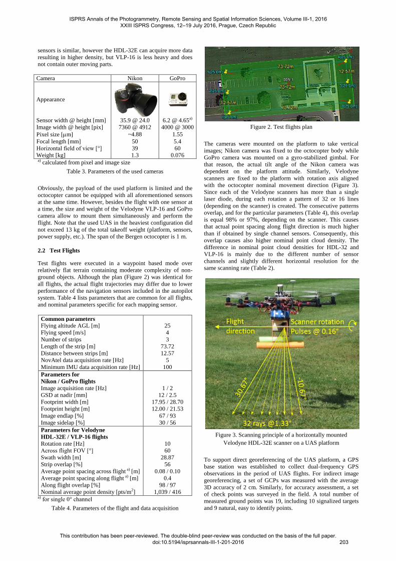
Figure 2. Test flights plan
The cameras were mounted on the platform to take vertical
images; Nikon camera was fixed to the octocopter body while
GoPro camera was mounted on a gyro-stabilized gimbal. For
that reason, the actual tilt angle of the Nikon camera was
dependent on the platform attitude. Similarly, Velodyne
scanners are fixed to the platform with rotation axis aligned
with the octocopter nominal movement direction (Figure 3).
Since each of the Velodyne scanners has more than a single
laser diode, during each rotation a pattern of 32 or 16 lines
(depending on the scanner) is created. The consecutive patterns
overlap, and for the particular parameters (Table 4), this overlap
is equal 98% or 97%, depending on the scanner. This causes
that actual point spacing along flight direction is much higher
than if obtained by single channel sensors. Consequently, this
overlap causes also higher nominal point cloud density. The
difference in nominal point cloud densities for HDL-32 and
VLP-16 is mainly due to the different number of sensor
channels and slightly different horizontal resolution for the
same scanning rate (Table 2).
Figure 3. Scanning principle of a horizontally mounted
Velodyne HDL-32E scanner on a UAS platform
To support direct georeferencing of the UAS platform, a GPS
base station was established to collect dual-frequency GPS
observations in the period of UAS flights. For indirect image
georeferencing, a set of GCPs was measured with the average
3D accuracy of 2 cm. Similarly, for accuracy assessment, a set
of check points was surveyed in the field. A total number of
measured ground points was 19, including 10 signalized targets
and 9 natural, easy to identify points.
ISPRS Annals of the Photogrammetry, Remote Sensing and Spatial Information Sciences, Volume III-1, 2016 XXIII ISPRS Congress, 12–19 July 2016, Prague, Czech Republic
This contribution has been peer-reviewed. The double-blind peer-review was conducted on the basis of the full paper. doi:10.5194/isprsannals-III-1-201-2016
203

3. METHODS
3.1 Dense Point Cloud Generation from Images
The image based point cloud was generated by the commercial
software that implements the standard workflow for UAS
images processing. In particular, first the bundle block
adjustment (BA) is applied (based on the GCPs) to find the
position and orientation of each image, and then the dense
image matching creates the dense point cloud.
3.2 Georeferencing of LiDAR Point Cloud
The generation of the georeferenced point cloud is the
transformation from the scanner local coordinates (scanner
frame s) to the global coordinates (frame g). The model of
generating local coordinates from the Velodyne raw
measurements for the channel k is as follow (Glennie and
Litchi, 2010):
(1)
where is the calibrated range
measurement
= raw range measurement
= range scale factor
= range offset
= vertical angle correction
= horizontal angle measurement encoder
= horizontal angle rotation correction
= horizontal offset from scanner origin
= vertical offset from scanner origin
The local scanner coordinates s of the point acquired at a time t are then georeferenced according to the model:
(2)
where
= coordinates of the body frame origin given
in the mapping frame g
is the rotation matrix
from the body frame b to the mapping frame g that is
dependent on the Euler angles: roll r, pitch p, and
heading h
= rotation matrix from the scanner frame s to the
body frame b that is dependent on the a priori rotation
matrix based on the body frame definition and scanner
assembly, and rotation caused by the boresight
misalignment
= lever-arm offset between scanner and body
frame origins defined in the body frame b
The Velodyne scanners are factory calibrated, i.e., all six
calibration parameters (see Eq. (1)) for each scanner channel are
known. In general, this simplifies georeferencing to the Eq. (2).
The intra-sensor calibration parameters, such as lever-arm
offsets between scanner and IMU origins or GPS antenna
reference point and IMU origin are usually obtained by direct
measurements and can be adjusted during processing. Similarly,
boresight misalignment is usually assumed to be zero on the
beginning and then can be adjusted during processing (Skaloud
and Lichti, 2006).
The essential part of the point cloud georeferencing is the
estimation of time dependent position and orientation of the
body frame in the global/mapping frame. This task is known as
platform direct georeferencing or trajectory reconstruction. The
six parameters (3D position and attitude) are usually estimated
by integrating GPS and IMU data where the body frame is
chosen as the IMU frame. The state-of-the-art in GPS/IMU data
integration is the Extended Kalman Filter (EKF); note that there
are many filter designs and implementations. In particular, the
integration can be executed in loosely or tightly coupled modes,
and the filters can differ by the state vector length (Jekeli,
2001). In this work the integration was performed in loosely-
coupled mode with the EKF state vector length of 21, including
3 positions, 3 velocities, 3 orientation angles, 3 gyro biases, 3
accelerometer biases, 3 gyro scale factors, and 3 accelerometer
scale factors.
3.3 Accuracy Assessment
The accuracy of the image based point cloud was evaluated
using precisely measured ground reference points. Since the
dense matching can provide points with RGB information for
almost every pixel of the image, the point spacing for the test
data was very high. Consequently, the identification of
corresponding reference points was possible. Based on the
coordinate residuals, both horizontal and vertical accuracies
were calculated.
In the case of LiDAR point clouds, direct comparison with
ground reference points is nearly impossible due to lower point
cloud density, as ground targets may be difficult to find based
on LiDAR intensity information and point coordinates. In
addition, sparse data introduces additional error. For example,
in our tests, the nominal average point spacing for Velodyne
VLP-16 point cloud is about 5 cm, and none of these points may
be exact reflection from the reference point measured directly in
the field. For that reason the accuracy of the point cloud must be
estimated in a different manner.
Since the LiDAR point clouds are usually used for surface
modeling, the vertical accuracy was estimated on the basis of
the created Digital Surface Model (DSM). After removing noise
points, the DSM of the GRID size equal 0.1 m was interpolated
and compared against heights of ground reference points. Based
on height residuals the vertical RMSE was calculated.
The surface modeling can also benefit in the estimation of the
accuracy for horizontal and vertical components separately.
Similarly to the evaluation of the image based point cloud
described above, a comparison with ground reference points can
be executed. However, points corresponding to reference are not
selected directly in the point cloud, but must be estimated
during a modeling process, e.g. as the intersection of modeled
edges. Obviously, such approach requires appropriate objects
that can be modeled from the point cloud in order to extract
feature points. In addition, the accuracy estimated using this
approach is affected by the accuracy of modeling, e.g. fitting
surfaces to the point cloud, surface intersecting, etc.
ISPRS Annals of the Photogrammetry, Remote Sensing and Spatial Information Sciences, Volume III-1, 2016 XXIII ISPRS Congress, 12–19 July 2016, Prague, Czech Republic
This contribution has been peer-reviewed. The double-blind peer-review was conducted on the basis of the full paper. doi:10.5194/isprsannals-III-1-201-2016
204

The point cloud based modeling of geometrical features can be
used to assess an internal accuracy of both types of point clouds.
From the georeferenced point cloud several subsets of points
can be extracted that belong to flat surfaces (e.g. building
roofs). Using least squares methods (LSQ), planar patches can
be fitted to each set of points allowing for calculating residuals
and other statistical parameters, including RMSE that can be
treated as an accuracy estimate. To avoid estimating the planar
patch parameters from outlier points, a robust LSQ may be
applied. Obtained estimate is a measure of internal 3D accuracy
(consistency) of the point cloud since selected planar patches
usually have different orientations.
The relative comparison of two types of point clouds (LiDAR
and imagery) can be also executed based on the planar patches.
In this case LiDAR point residuals are computed with respect to
planar patches estimated from the image point cloud. These
values cannot be considered as absolute accuracy of the LiDAR
point cloud, because the accuracy of the image point cloud,
obtained even form high resolution and good geometry images
may be too low to treat them as a reference. However, such
approach can indirectly compare two types of point clouds.
LiDAR and image point clouds can be also compared directly.
For well mapped objects, a set of corresponding point clouds
can be extracted and the distance between LiDAR with respect
to image based point cloud, treated as the reference, can be
calculated. Obtained values may provide relative point cloud
accuracy.
4. RESULTS AND DISCUSSION
Depending on the test flight, the GPS positions estimated from
the NovAtel data showed 3D accuracy of 10 cm or better. The
analysis of IMU data showed strong noise in accelerometer
readings. Table 5 shows the mean accelerometer readings for
two parts of the flight, including the system test before the
takeoff; note that both IMUs were aligned to have the same
orientation of Z axis (opposite polarity) and then the axis X of
one IMU corresponded to the axis Y of the other IMU.
Test case IMU
Mean of accelerometer
readings [m/s2]
Total X Y Z
Static MicroStrain 9.81 0.96 0.21 -9.43
(motors off) Epson 9.81 0.21 0.91 9.44
Inflight MicroStrain 8.88 -0.02 0.38 -8.28
(motors on) Epson 9.72 -0.57 -0.22 8.49
Table 5. Analysis of accelerometer readings for the flight with
Velodyne HDL-32E
To integrate unreliable IMU data with relatively good GPS
positions, the parameters of the EKF were tuned to account for
the high acceleration noise. This approach caused that obtained
positions were nearly identical to positions calculated from GPS
data, and the calculated platform orientation was mainly
dependent on gyro readings. In addition to the 6DoF trajectory
reconstruction by GPS/IMU data integration, the 6DoF
octocopter trajectory for one flight was obtained from imagery
data as a result of BA. This allowed to see the impact of the
noisy IMU data to the platform orientation.
Since properly executed indirect georeferencing is usually more
accurate than direct georeferencing, the GCPs based BA
solution based on the good geometry Nikon imagery was treated
as a reference. Because the reference solution was estimated
with 1 Hz rate, only the corresponding part of GPS/IMU
solution was compared. The comparison of the GPS and
reference BA trajectory points showed that the actual 3D
accuracy of GPS positions with respect to reference BA solution
was about 4 cm. The analysis of the attitude (Figure 4) showed
that the solution obtained from MicroStrain data is very similar
to the reference, but the solution from Epson data is not reliable
because it shows very large tilt angle (even 50º) that would
cause the octocopter to crash if this tilt happens in the reality.
For that reason, the direct georeferencing of the LiDAR point
cloud was performed using the MicroStrain solution. The
unreliable attitude obtained from Epson data may be explained
by very strong influence of motor vibrations to Epson gyro
readings.
Figure 4. Euler angles obtained from GSP/IMU data integration using modified EKF and Nikon images (reference)
ISPRS Annals of the Photogrammetry, Remote Sensing and Spatial Information Sciences, Volume III-1, 2016 XXIII ISPRS Congress, 12–19 July 2016, Prague, Czech Republic
This contribution has been peer-reviewed. The double-blind peer-review was conducted on the basis of the full paper. doi:10.5194/isprsannals-III-1-201-2016
205

(a)
(b)
(c)
(d)
Figure 5. Obtained point clouds: Velodyne HDL-32E - heights (a), Nikon - heights (b), Velodyne HDL-32E - intensity (c), Nikon -
RGB (d)
Results of the georeferenced point clouds obtained from
Velodyne HDL-32E scanner data and Nikon images are shown
in Figure 5. Clearly, the LiDAR point cloud is more complete as
it contains reflections from the objects that lack the texture
necessary for dense image matching (roofs) and objects that
were moving during data acquisition – wind caused the
movement of tree branches. The Velodyne point cloud is also
sparser than the point cloud obtained from Nikon images. The
calculated point cloud density is 867 and 12,429 pts/m2 for the
Velodyne HDL-32E and Nikon point clouds, respectively.
However, the point cloud density for used LiDAR sensor is still
much larger than obtained from traditional airborne LiDAR
systems. The detailed analysis of the Velodyne point cloud
geometry showed issues with the trajectory reconstruction,
because many points were unaligned with flat surfaces (e.g.
building roofs), and edges of the straight objects (e.g. curb
ISPRS Annals of the Photogrammetry, Remote Sensing and Spatial Information Sciences, Volume III-1, 2016 XXIII ISPRS Congress, 12–19 July 2016, Prague, Czech Republic
This contribution has been peer-reviewed. The double-blind peer-review was conducted on the basis of the full paper. doi:10.5194/isprsannals-III-1-201-2016
206

separating parking lot from the lawn, and edges of buildings)
were not straight. For that reason, only initial estimate of
absolute vertical accuracy of created DSM was computed and
was equal 0.49 and 0.03 m for Velodyne and Nikon point
clouds, respectively. As reported earlier (Toth et al., 2015) the
absolute 3D accuracy of Nikon point cloud is 7 cm, this point
cloud can be used as the reference in the relative comparison
with the Velodyne point cloud. 3D distances between Velodyne
and Nikon point clouds were calculated using the
CloudCompare software (Girardeau-Montaut, 2016) resulting in
the average distance of 0.90 m; the standard deviation of these
distances was 0.65 m. Obtained values are rather large
comparing to the accuracy of the Velodyne HDL-32E range
measurements or the accuracy of positioning using geodetic
grade GPS receiver. Further improvement of the UAS LiDAR
point cloud requires more accurate estimation of the platform
attitude.
5. POSSIBILITIES OF LIDAR POINT CLOUD
IMPROVEMENT
5.1 Trajectory Reconstruction with Imagery Data
There are few aspects to improve the UAS Velodyne point
cloud accuracy for the investigated hardware in this study. First
is the reduction of the vibration impact on the IMU readings.
This may be obtained by modifying the mount and adding
dampers to isolate the IMU and scanner from the vibrating
octocopter frame. Obviously, IMU and LiDAR sensor should
not be isolated.
The use of multiple laser diodes in one sensor may be
potentially beneficial in refinement of the platform attitude.
Because all Velodyne pulses for the same horizontal angle are
emitted nearly simultaneously, created profiles from different
rotations may be matched adding constraints to the attitude
estimation. However, this approach needs further algorithmic
developments.
Finally, the 6DoF trajectory of the UAS can be estimated also
from the imagery data without any data from navigation
sensors. In this case, the position and orientation is computed
for each taken image. This task can be solved by image block
BA based on GCPs. Consequently, for the LiDAR point cloud
georeferencing, the sensor body is the image frame instead of
IMU frame. Such type of solution can be beneficial if the IMU
data is not reliable, e.g. affected by the motor vibrations (Zhe et
al., 2015). The requirement is that the LiDAR and imagery data
needs to be acquired during the same flight. In the case of the
testing platform, due to its limited payload capacity, only
Velodyne VLP-16 and GoPro camera could be mounted at the
same time on the octocopter.
Since the GoPro camera does not provide accurate time of
image acquisition, the reconstructed points based on BA
trajectory lack the time stamps. Obviously, the NovAtel GPS
data is able to provide reliable time and position of the platform.
The trajectories (3DoF) obtained from images and GPS data can
be matched and interpolated to get the time dependent 6DoF
trajectory and to georeference the LiDAR point cloud according
to Eq. (2). In this case, the platform orientation is transferred
from the image BA results and the time stamps are transferred
from the GPS data. Since both solutions are of much lower rate
than the LiDAR data acquisition, interpolation is necessary.
Finally, the accuracy of the point cloud will be then also
dependent on the flight dynamics, and the chosen interpolation
model.
6. CONCLUSIONS AND FUTURE WORK
This work showed initial results of the performance assessment
of the UAS LiDAR point cloud obtained with the Velodyne
sensor. The analysis was executed to assess the performance of
dual-frequency GPS and medium-grade MEMS IMU sensors in
the trajectory reconstruction for georeferencing LiDAR point
cloud. The results showed that miniaturized dual-frequency
GPS receivers are suitable for direct georeferencing of the UAS
platform while some of the IMU sensors experience strong
vibrations caused by platform motors that degrades their
performance. The reduced IMU performance resulted in
decreased accuracy of the LiDAR point cloud that was 0.49 m
for the vertical component, and was much lower than the
accuracy of the point cloud created from images taken during
similar flights. The relative comparison between these point
clouds showed that the accuracy of the horizontal component of
the LiDAR point cloud is in the same magnitude as for vertical
component. Although the LiDAR point cloud is sparser than
image point cloud, in many situations, it is more complete as it
allows to map dynamic scenarios and objects that lack of the
texture necessary for dense image matching.
Reducing the impact of vibration, e.g. by adding mechanical
dampers to the IMU mount will be investigated in the future. A
promising result of accurate platform direct georeferencing was
obtained by trajectory reconstruction based on imagery data.
The georeferencing of the LiDAR point cloud based on the
solution obtained by indirect georeferencing of images will be
investigated in the future by performing simultaneous flight
with light-weight Velodyne VLP-16 laser scanner and GoPro
camera.
REFERENCES
Amon, P., Riegl, U., Rieger, P., Pfennigbauer, M., 2015. UAV-
based laser scanning to meet special challenges in lidar
surveying. Proceedings of the Geomatics Indaba 2015
conference, August 11-13, 2015, Ekurhuleni, Gauteng, South
Africa, online.
El-Sheimy, N., 2009. Emerging MEMS IMU and its impact on
mapping applications. Photogrammetric Week, Stuttgart,
Germany.
Girardeau-Montaut, D., 2016. CloudCompare - Open Source
project. Online: http://www.danielgm.net/cc/ (accessed
30.03.2016).
Glennie, C., Lichti, D.D., 2010. Static calibration and analysis
of the Velodyne HDL-64E S2 for high accuracy mobile
scanning. Remote Sensing, 2(6), pp.1610-1624.
Hirose, M., Xiao, Y., Zuo, Z., Kamat, V. R., Zekkos, D., Lynch,
J., 2015. Implementation of UAV localization methods for a
mobile post-earthquake monitoring system. 2015 IEEE
Workshop on Environmental, Energy and Structural Monitoring
Systems (EESMS), July 9-10, 2015, pp. 66-71.
Jekeli, C., 2001. Inertial navigation systems with geodetic
applications. Walter de Gruyter.
Kuhnert, K.D., Kuhnert, L., 2013. Light-weight sensor package
for precision 3D measurement with micro UAVs e. g. power-
line monitoring. International Archives of the Photogrammetry,
Remote Sensing and Spatial Information Sciences, XL-1/W2,
pp. 235–40.
ISPRS Annals of the Photogrammetry, Remote Sensing and Spatial Information Sciences, Volume III-1, 2016 XXIII ISPRS Congress, 12–19 July 2016, Prague, Czech Republic
This contribution has been peer-reviewed. The double-blind peer-review was conducted on the basis of the full paper. doi:10.5194/isprsannals-III-1-201-2016
207

Lin, Y., Hyyppä, J., Jaakkola, A., 2011. Mini-UAV-borne
LIDAR for fine-scale mapping. IEEE Geoscience and Remote
Sensing Letters, 8(3), pp. 426-430.
Mandlburger, G., Pfennigbauer, M., Riegl, U., Haring, A.,
Wieser, M., Glira, P., Winiwarter, L., 2015. Complementing
airborne laser bathymetry with UAV-based lidar for capturing
alluvial landscapes. Proceedings of SPIE 9637, Remote Sensing
for Agriculture, Ecosystems, and Hydrology XVII, 96370A,
October 14, 2015, Toulouse, France, pp. 1-14.
Nagai, M., Chen, T., Shibasaki, R., Kumagai, H., Ahmed, A.,
2009. UAV-borne 3-D mapping system by multisensor
integration. IEEE Transactions on Geoscience and Remote
Sensing, 47(3), pp. 701-708.
Roca, D., Armesto, J., Lagüela, S., Díaz-Vilariño, L., 2014.
LIDAR-equipped UAV for building information modelling.
International Archives of the Photogrammetry, Remote Sensing
and Spatial Information Sciences, XL-5, pp. 523-527.
Skaloud, J., Lichti, D., 2006. Rigorous approach to bore-sight
self-calibration in airborne laser scanning. ISPRS Journal of
Photogrammetry and Remote Sensing, 61(1), 47-59.
Toth, C., Jozkow, G., and Grejner-Brzezinska, D., 2015.
Mapping with Small UAS: A Point Cloud Accuracy
Assessment. Journal of Applied Geodesy, 9(4), pp. 213–226.
Tulldahl, H. M., Larsson, H., 2014. Lidar on small UAV for 3D
mapping. Proceedings of SPIE Security+ Defence conference,
International Society for Optics and Photonics, pp. 925009-
925009.
Wallace, L., Lucieer, A., Watson, C., Turner, D., 2012.
Development of a UAV-LiDAR system with application to
forest inventory. Remote Sensing, 4(6), pp. 1519-1543.
Yang, B., Chen, C., 2015. Automatic registration of UAV-borne
sequent images and LiDAR data. ISPRS Journal of
Photogrammetry and Remote Sensing, 101, pp. 262-274.
Zhe, L., Yu, Y., Yabing, J., ShuGuang, Z., 2015. The Design
and Testing of a LiDAR Platform for a UAV for Heritage
Mapping. International Archives of the Photogrammetry,
Remote Sensing and Spatial Information Sciences, XL-1/W4,
pp, 17-24.
ISPRS Annals of the Photogrammetry, Remote Sensing and Spatial Information Sciences, Volume III-1, 2016 XXIII ISPRS Congress, 12–19 July 2016, Prague, Czech Republic
This contribution has been peer-reviewed. The double-blind peer-review was conducted on the basis of the full paper. doi:10.5194/isprsannals-III-1-201-2016
208