TYPICAL PLAN CURVE - Hamilton · Concrete Thrust Blocks ... 2.0m vertical height of riser Pipe...
21
D5.1 top of manhole cover Ground level flush with 3 1 top of manhole cover Ground level flush with 1050 Chimney Slab Chamber Manhole 450 450 1800 L e ng t h m a x 23 Radius minimum 2.5 x Pipe ( Mi n ) 2 2 5 450 250 150 Precast flanged base 150 (Max) 600 (Max) 600 80 300 300 Manhole top slab manhole cover flush with top of Ground level Precast flanged base Stormwater manholes may use concrete. Wastewater manholes to use ceramic for channelling. 2. Diameters of precast manhole pipes are nominal only. 1. NOTES: THROUGH MANHOLE TYPICAL PLAN CURVE DETAILS 1050 & 1200 MANHOLES DETAILS 1350 AND OVER MANHOLES Manhole top slab 3 1 450 150 top of manhole cover Ground level flush with into undisturbed ground. with 4/12 bars min. length 300mm Concrete slab 450wide x 100deep bars with Denso tape carry through. Wrap Flexible joint reinf: To (Wastewater Only) 100 DROP MANHOLES top slab Manhole top slab Manhole 1050 - 1350 MANHOLES City Council INFRASTRUCTURE TECHNICAL SPECIFICATION Version: NOVEMBER 2012 Precast flanged base
Transcript of TYPICAL PLAN CURVE - Hamilton · Concrete Thrust Blocks ... 2.0m vertical height of riser Pipe...

D5.1
top of manhole coverGround level flush with
31
top of manhole coverGround level flush with
1050Ø Chimney
SlabChamberManhole
450
450
1800 L
ength m
ax
23
Radius minimum 2.5 x Pipe Ø
(Min)
225
450
250
150
Precast flanged base
150
(Max)600
(Max)600
80
300
300
Manhole top slab
manhole coverflush with top of Ground level
Precast flanged base
Stormwater manholes may use concrete.Wastewater manholes to use ceramic for channelling. 2.
Diameters of precast manhole pipes are nominal only.1.
NOTES:
THROUGH MANHOLE
TYPICAL PLAN CURVE
DETAILS 1050Ø & 1200Ø MANHOLES DETAILS 1350Ø AND OVER MANHOLES
Manhole top slab
31
450
150
top of manhole coverGround level flush with
into undisturbed ground.with 4/12 bars min. length 300mm Concrete slab 450wide x 100deep
bars with Denso tapecarry through. Wrap Flexible joint reinf: To
(Wastewater Only)
100
DROP MANHOLES
top slabManhole
top slabManhole
1050Ø - 1350Ø MANHOLES
City Council
INFRASTRUCTURE TECHNICAL SPECIFICATION Version: NOVEMBER 2012
Precast flanged base
D5.2
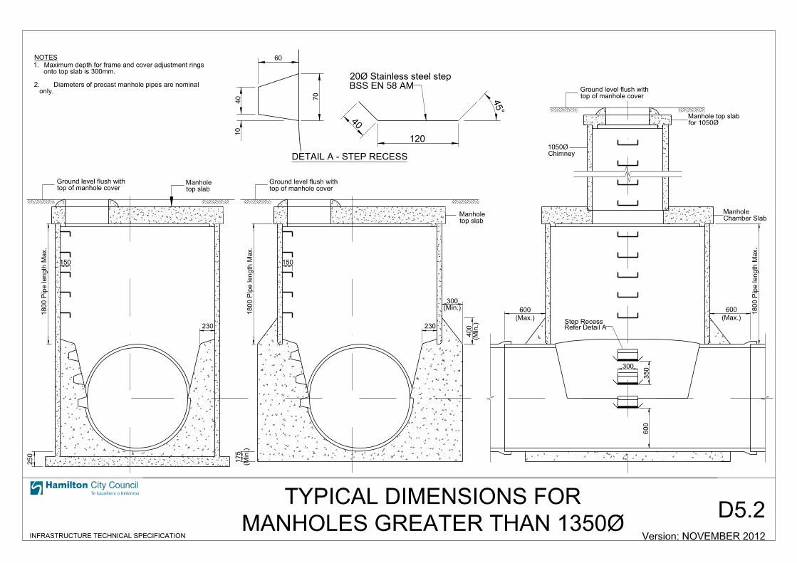
only. Diameters of precast manhole pipes are nominal 2.
onto top slab is 300mm.Maximum depth for frame and cover adjustment rings 1.
top of manhole cover
Ground level flush with
top of manhole coverGround level flush with
Chamber SlabManhole
Chimney1050Ø
1800 Pipe length M
ax.
150
230
(Min.)300
(Min.)
400
for 1050ØManhole top slab
Refer Detail AStep Recess
(Max.)
600
1800 Pipe length M
ax.
300
350
600
60
40
10
70
40
120
BSS EN 58 AM
20Ø Stainless steel step
DETAIL A - STEP RECESS
NOTES
top of manhole coverGround level flush with
250
1800 Pipe length M
ax.
150
230
top slabManhole
top slabManhole
(Min.)
175
(Max.)
600
City Council
INFRASTRUCTURE TECHNICAL SPECIFICATION Version: NOVEMBER 2012MANHOLES GREATER THAN 1350Ø
TYPICAL DIMENSIONS FOR

D5.3
With Top of MH Cover
Ground Level Flush
1
1
250 Min.
shallow chamber
Top slab for 750Ø
75 75
872
Top Slab for 750Ø Shallow Chamber
and where depth of invert is less than 1000mmTo be used only on pipes of 100mm to 300mm Ø
2/12Ø Circular 320 lap
585Ø Min.
750Ø
750Ø Internal Shallow Chamber
1000 M
ax.
City Council
INFRASTRUCTURE TECHNICAL SPECIFICATION
SHALLOW MANHOLES
Version: NOVEMBER 2012
D5.4
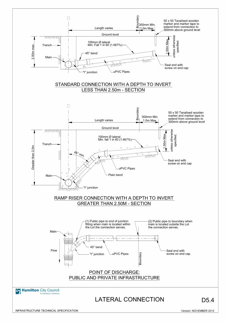
Plain bend
’Y’ junction
Length varies
Length varies
Boundary
Boundary
1.0m Max.
300mm Min.
2.5
0m m
ax
Gre
ater th
an 2.5
mGround level
Ground level
1.5
0m M
ax.
1.5
0m M
ax.
screw on end cap
Seal end with
�
�
’Y’ junction
specifie
d.
unless oth
erwise
’Y’ junction
Boundary
screw on end cap.
Seal end with
uPVC Pipes
uPVC Pipes
uPVC Pipes
Flow
300mm above ground level
extend from connection to
marker and marker tape to
50 x 50 Tanalised wooden
Trench
Trench
specifie
d.
unless oth
erwise
300mm above ground level
extend from connection to
marker and marker tape to
50 x 50 Tanalised wooden
1.0m Max.
300mm Min.
screw on end cap
Seal end with
the Lot the connection serves.
fitting when main is located within
(1) Public pipe to end of junction
City Council
INFRASTRUCTURE TECHNICAL SPECIFICATION
LATERAL CONNECTION
Version: NOVEMBER 2012
PUBLIC AND PRIVATE INFRASTRUCTURE
POINT OF DISCHARGE:
Main
Main
the connection serves.
main is located outside the Lot
(2) Public pipe to boundary when
Main
GREATER THAN 2.50M - SECTION
RAMP RISER CONNECTION WITH A DEPTH TO INVERT
LESS THAN 2.50m - SECTION
STANDARD CONNECTION WITH A DEPTH TO INVERT
D5.5
City Council
INFRASTRUCTURE TECHNICAL SPECIFICATION Version: NOVEMBER 2012
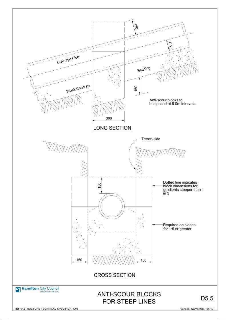
FOR STEEP LINES
ANTI-SCOUR BLOCKS
Bedding
300
D/2
150
150
Drainag
e Pipe
Trench side
150
150150
in 3gradients steeper than 1 block dimensions for Dotted line indicates
Weak Con
crete
be spaced at 5.0m intervalsAnti-scour blocks to
for 1:5 or greater
Required on slopes
CROSS SECTION
LONG SECTION

D5.6
2.0
m Min. Cleara
nce
2.0
m Min. Cleara
nce
Manhole
Piles
Retaining PostGround Level
Ground Level
Influence Line
Pipe Invert
First row of piles
of piles
Subsequent row
pile clearance
1.5m Min.
between piles
shall be self-supporting and span
envelope the structure
influence line
1.0
m Min. belo
w
influence line
1.0
m Min. belo
w
pipe invert
1.0
m Min. belo
w
ELEVATION
Piles
Building
clearance1.5m Min. Pile
clearance1.5m Min. Pile
Building
Manhole
manhole structure
Outside wall of the
ZONE OF INFLUENCE
See Note 2.
(Only permitted if an alternative alignment is not possible)
manhole structure
Outside wall of the
BUILDING ADJACENT TO A PUBLIC MAIN
PLAN
BUILDING OVER A PUBLIC MAIN
PLAN
City Council
INFRASTRUCTURE TECHNICAL SPECIFICATION Version: NOVEMBER 2012
Public Main
Public Main
BUILDING OVER AND ADJACENT TO PIPELINES
clearancePile
1.5m Min.
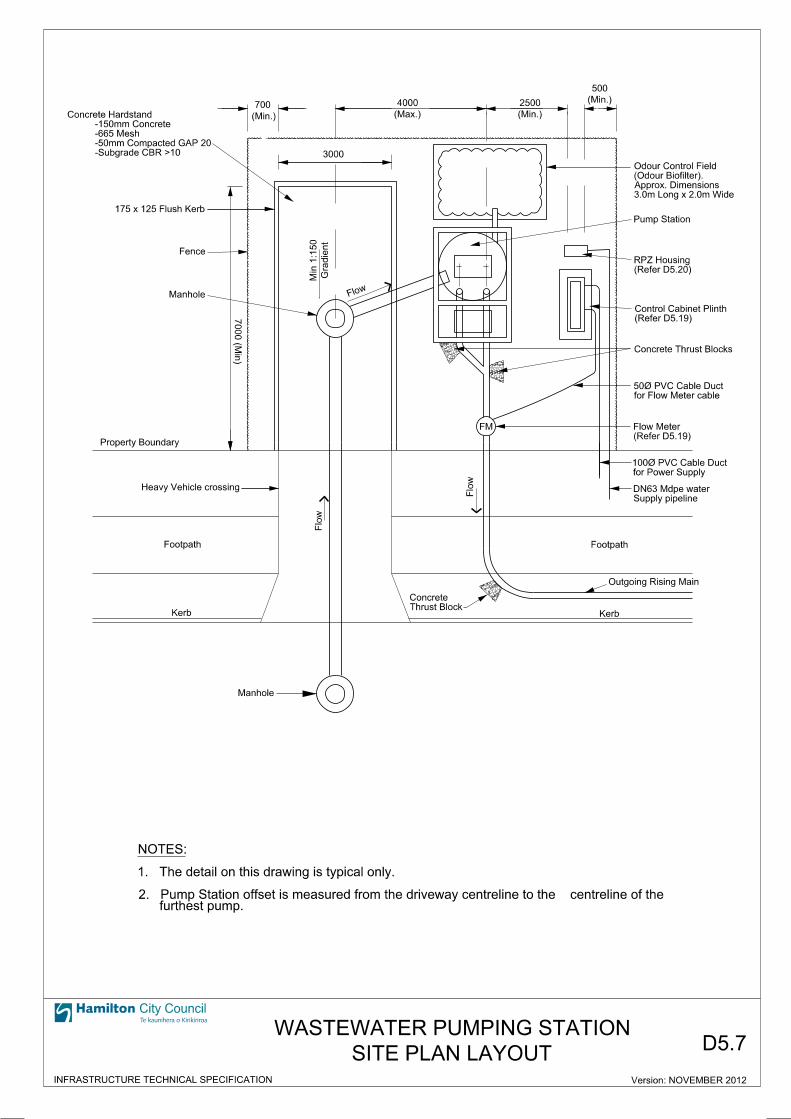
Flow
FM
3000
(Min.)
700
Pump Station
(Max.)
4000
(Min.)
2500 (Min.)
500
for Flow Meter cable
50Ø PVC Cable Duct
Gra
die
nt
Min 1:1
50
Concrete Thrust Blocks
3.0m Long x 2.0m Wide
Approx. Dimensions
(Odour Biofilter).
Odour Control Field
175 x 125 Flush Kerb
-Subgrade CBR >10
-50mm Compacted GAP 20
-665 Mesh
-150mm Concrete
Concrete Hardstand
Property Boundary
7000 (M
in)
Manhole
Flo
w
Flo
w
Footpath
KerbThrust Block
Concrete
Supply pipeline
DN63 Mdpe water
for Power Supply
100Ø PVC Cable Duct
Outgoing Rising Main
Footpath
Kerb
(Refer D5.20)
RPZ Housing
Heavy Vehicle crossing
(Refer D5.19)
Control Cabinet Plinth
Manhole
D5.7
City Council
INFRASTRUCTURE TECHNICAL SPECIFICATION Version: NOVEMBER 2012
SITE PLAN LAYOUT
WASTEWATER PUMPING STATION
(Refer D5.19)
Flow Meter
Fence
furthest pump.2. Pump Station offset is measured from the driveway centreline to the centreline of the
1. The detail on this drawing is typical only.
NOTES:
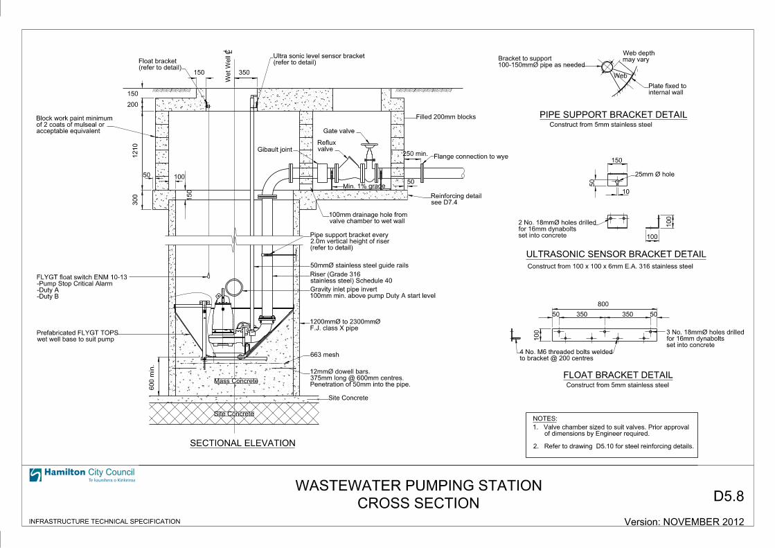
Penetration of 50mm into the pipe.375mm long @ 600mm centres.12mmØ dowell bars.
Site Concrete
Site Concrete
663 mesh
(refer to detail)2.0m vertical height of riserPipe support bracket every
valve chamber to wet wall100mm drainage hole from
Min. 1% grade
Gibault joint valveReflux
Gate valve
Filled 200mm blocks
(refer to detail)Ultra sonic level sensor bracket
(refer to detail)Float bracket
150 350
600 min.
300
150
1210
200
150
50 100
250 min.
50
to bracket @ 200 centres4 No. M6 threaded bolts welded
set into concretefor 16mm dynabolts 3 No. 18mmØ holes drilled
800
350 35050 50
100
Construct from 5mm stainless steel
100
100
10
50
150
set into concretefor 16mm dynabolts 2 No. 18mmØ holes drilled
25mm Ø hole
Construct from 5mm stainless steel
internal wallPlate fixed to
may varyWeb depth
100-150mmØ pipe as neededBracket to support
Web
SECTIONAL ELEVATION
ULTRASONIC SENSOR BRACKET DETAIL
PIPE SUPPORT BRACKET DETAIL
FLOAT BRACKET DETAIL
NOTES:
acceptable equivalentof 2 coats of mulseal or Block work paint minimum
stainless steel) Schedule 40Riser (Grade 316
100mm min. above pump Duty A start levelGravity inlet pipe invert
F.J. class X pipe1200mmØ to 2300mmØ
see D7.4Reinforcing detail
wet well base to suit pumpPrefabricated FLYGT TOPS
Flange connection to wye
Construct from 100 x 100 x 6mm E.A. 316 stainless steel
Mass Concrete
D5.8
City Council
INFRASTRUCTURE TECHNICAL SPECIFICATION Version: NOVEMBER 2012
2. Refer to drawing D5.10 for steel reinforcing details.
of dimensions by Engineer required.1. Valve chamber sized to suit valves. Prior approval
50mmØ stainless steel guide rails
-Duty B-Duty A-Pump Stop Critical AlarmFLYGT float switch ENM 10-13
DW
et
Well
CROSS SECTION
WASTEWATER PUMPING STATION
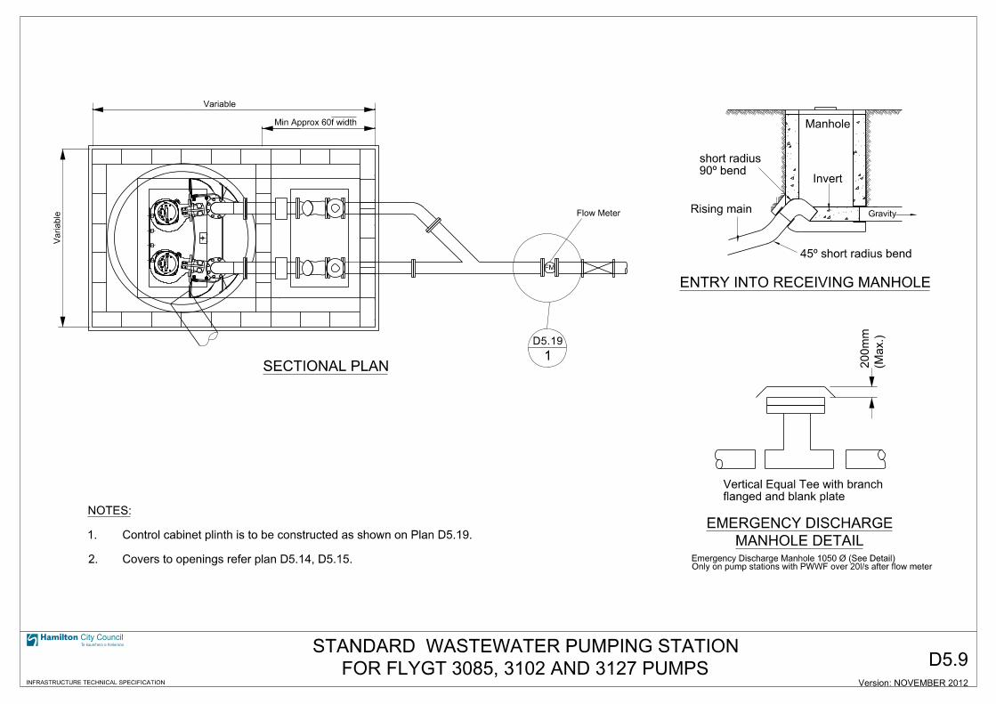
D5.9
SECTIONAL PLAN
Manhole
ENTRY INTO RECEIVING MANHOLE
MANHOLE DETAIL
EMERGENCY DISCHARGE
Invert
Gravity
45” short radius bend
90” bend
short radius
Rising main
flanged and blank plate
Vertical Equal Tee with branch
FOR FLYGT 3085, 3102 AND 3127 PUMPS
STANDARD WASTEWATER PUMPING STATION
Only on pump stations with PWWF over 20l/s after flow meterEmergency Discharge Manhole 1050 Ø (See Detail)
Flow Meter
1
Variable
Variable
f widthMin Approx 60
FM
(Max.)
200
mm
City Council
INFRASTRUCTURE TECHNICAL SPECIFICATION Version: NOVEMBER 2012
D5.19
Covers to openings refer plan D5.14, D5.15.2.
Control cabinet plinth is to be constructed as shown on Plan D5.19.1.
NOTES:
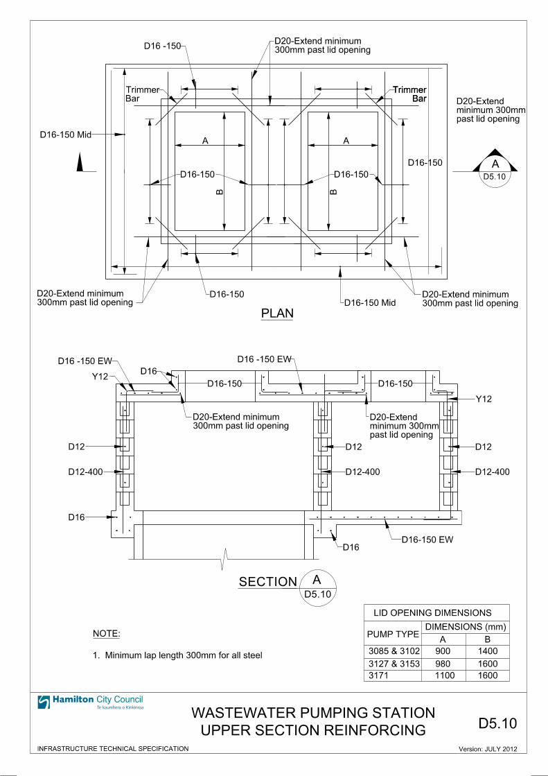
Version: JULY 2012
3085 & 3102
3127 & 3153
3171
PUMP TYPEA B
DIMENSIONS (mm)
LID OPENING DIMENSIONS
D16 -150
BarTrimmer
D16-150 Mid
300mm past lid openingD20-Extend minimum
D16-150
D16-150 Mid300mm past lid openingD20-Extend minimum D16-150
past lid openingminimum 300mmD20-Extend
A
D16 -150 EW
Y12D16
D12
D12-400
D16
D16-150
D16 -150 EW
D16-150
Y12
D12
D12-400
D16-150 EWD16
300mm past lid openingD20-Extend minimum
past lid openingminimum 300mmD20-Extend
D12
D12-400
A
A
PLAN
BarTrimmer
A
BarTrimmer
D16-150
D16-150
300mm past lid openingD20-Extend minimum
900
980
1100
1400
1600
1600
B
SECTION
B
1. Minimum lap length 300mm for all steel
NOTE:
D5.10
D5.10
City Council
INFRASTRUCTURE TECHNICAL SPECIFICATION
UPPER SECTION REINFORCING
WASTEWATER PUMPING STATIOND5.10
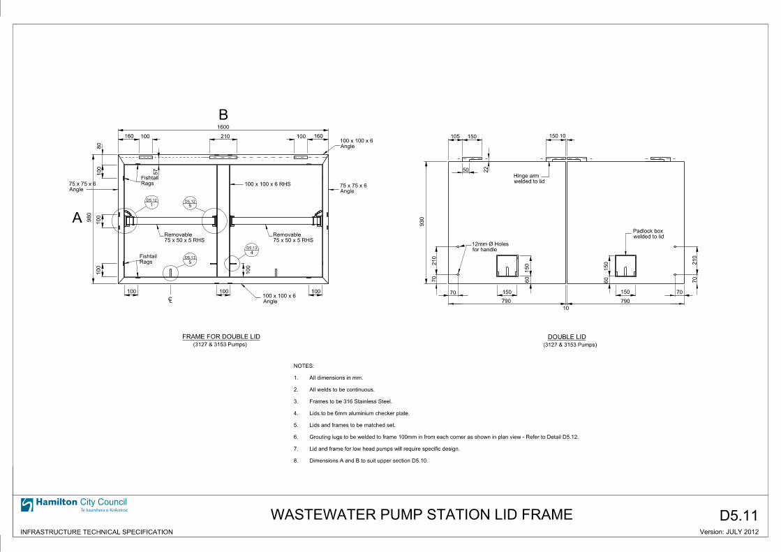
D5.11
Rags
Fishtail
75 x 50 x 5 RHS
Removable
Rags
Fishtail
75 x 50 x 5 RHS
Removable
100 x 100 x 6 RHS
100
FRAME FOR DOUBLE LID
(3127 & 3153 Pumps)
80
100
100
100
980
160160 100 100210
1600
57
100100100
(3127 & 3153 Pumps)
DOUBLE LID
for handle
12mm Ø Holes
welded to lid
Padlock box
welded to lid
Hinge arm
210
70
930
150
790
70
60
150
60
150
790
150 70
210
70
10
150105
50 22
15010
1 5
4
Angle
100 x 100 x 6
Angle
75 x 75 x 6Angle
75 x 75 x 6
5
Version: JULY 2012
LC
City Council
INFRASTRUCTURE TECHNICAL SPECIFICATION
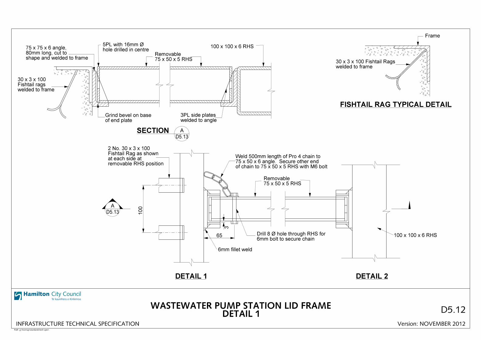
WASTEWATER PUMP STATION LID FRAME
D5.13
D5.13
D5.12 D5.12
B
A
Angle
100 x 100 x 6
Dimensions A and B to suit upper section D5.10.8.
Lid and frame for low head pumps will require specific design.7.
Grouting lugs to be welded to frame 100mm in from each corner as shown in plan view - Refer to Detail D5.12.6.
Lids and frames to be matched set.5.
Lids to be 6mm aluminium checker plate.4.
Frames to be 316 Stainless Steel.3.
All welds to be continuous.2.
All dimensions in mm.1.
NOTES:
City Council
Path g:\hccmap\standards\tech spec\
hole drilled in centre5PL with 16mm Ø
75 x 50 x 5 RHSRemovable
100 x 100 x 6 RHS
of end plateGrind bevel on base
welded to angle3PL side plates
75 x 50 x 5 RHSRemovable
Frame
welded to frame30 x 3 x 100 Fishtail Rags
welded to frameFishtail rags30 x 3 x 100
removable RHS positionat each side atFishtail Rag as shown2 No. 30 x 3 x 100
100
3
65
of chain to 75 x 50 x 5 RHS with M6 bolt75 x 50 x 6 angle. Secure other endWeld 500mm length of Pro 4 chain to
6mm bolt to secure chainDrill 8 Ø hole through RHS for
6mm fillet weld
100 x 100 x 6 RHS
FISHTAIL RAG TYPICAL DETAIL
A
SECTION A
DETAIL 1 DETAIL 2
D5.12
shape and welded to frame80mm long, cut to75 x 75 x 6 angle,
DETAIL 1WASTEWATER PUMP STATION LID FRAME
Version: NOVEMBER 2012INFRASTRUCTURE TECHNICAL SPECIFICATION
D5.13
D5.13

City Council
Path g:\hccmap\standards\tech spec\
D5.13
50
50
to frameform hook and welded6mm Ø rod bent to
RHS100 x 100 x 6
possible to duct for Electricianto pump frame as close asDetail of Bolt to be attached
10mm Ø bolt
Weld this side only
6mm fillet weld
12mm Ø hole
10
A
40
30
45
60
12mm Ø hole
SECTION A
5DETAIL
4DETAIL
75 x 75 x 6 angle
75 x 75 x 6 angle
angle75 x 75 x 6
INFRASTRUCTURE TECHNICAL SPECIFICATION Version: November 2012
DETAIL 2
WASTEWATER PUMP STATION LID FRAME
D5.12
D5.12
well chamber required in wetNote: Chain hook only
D5.12
D5.12

City Council
Path g:\hccmap\standards\tech spec\
SIDE ELEVATION
150
150
padlock bracketSection removed for
80
20
10mm Ø Handle
6mm Lid
for handle12mm Ø Hole
30mm Ø hole
aluminum chequer plateHinged 150 x 150 x 6mm
cut in padlock boxresting in groove,10mm Ø hinge rod
70padlock bracketSection removed for
chequer plate6mm aluminium
80
74
50
Hinge rod10mm Ø
bracketfor padlockSection removed
hinge pinhinge arm to form16Ø rod welded to
sit on angleHinge pin shall
PLAN
LIFTING HANDLE TYPICAL DETAIL
PADLOCK BOX TYPICAL DETAIL
LID HINGE TYPICAL DETAIL
hinge rodto hold 10mm ØGroove cut out
SECTION A
support plate10mm aluminum
100 x 100 x 6 angle
with bottom cut offor 20mm Ø (internal) pipe angle to form hinge housing 6PL bent and welded to
Support Plate10mm Aluminum
6mm aluminum plate
plate6mm Aluminum
210
INFRASTRUCTURE TECHNICAL SPECIFICATION
D5.14
Version: NOVEMBER 2012
WASTEWATER PUMP STATION LID DETAILS
D5.13
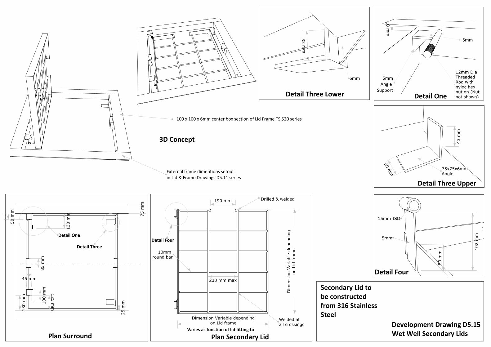
75 m
m
Detail One
Detail One
Plan Surround
12mm Dia Threaded Rod with nyloc hex nut on (Nut not shown)
125 mm
85 m
m
25 m
m100
mm
Detail Three
Detail Three Upper
Detail Three Lower50 m
m 75x75x6mm Angle
Plan Secondary Lid
Dimension Variable dependingon Lid frame
190 mm
10mm round bar
Dim
ensi
on V
aria
ble
depe
ndin
gon
Lid
fra
me
230 mm max
Detail Four
Detail Four
3D Concept
50 m
m
5mm
15mm ISD
5mmAngle
Support
Secondary Lid to be constructed from 316 Stainless Steel
External frame dimentions setout in Lid & Frame Drawings D5.11 series
Varies as function of lid fitting toDevelopment Drawing D5.15Wet Well Secondary Lids
Welded at all crossings
Drilled & welded
43 m
m
102
mm
130
mm
10 mm
130
mm
5mm
50 m
m
100 x 100 x 6mm center box section of Lid Frame TS 520 series
45 mm
32 mm
6mm
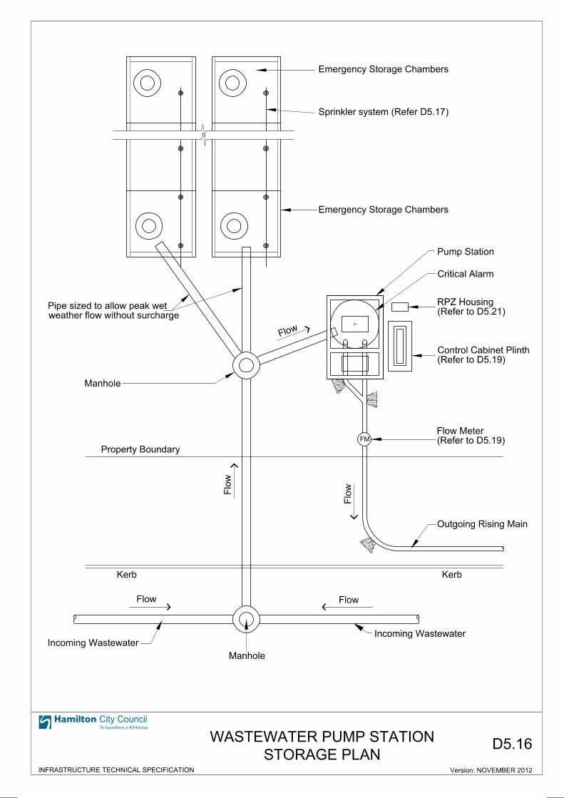
Emergency Storage Chambers
Emergency Storage Chambers
weather flow without surcharge
Pipe sized to allow peak wet
Manhole
Property Boundary
Outgoing Rising Main
Kerb
FM
Incoming WastewaterIncoming Wastewater
Kerb
Flow
Manhole
Flow
Flo
w
Flo
w
Flow
Pump Station
Sprinkler system (Refer D5.17)
(Refer to D5.21)
RPZ Housing
(Refer to D5.19)
Control Cabinet Plinth
(Refer to D5.19)
Flow Meter
Critical Alarm
City Council
INFRASTRUCTURE TECHNICAL SPECIFICATION Version: NOVEMBER 2012
D5.16STORAGE PLAN
WASTEWATER PUMP STATION
Version: JULY 2012
A
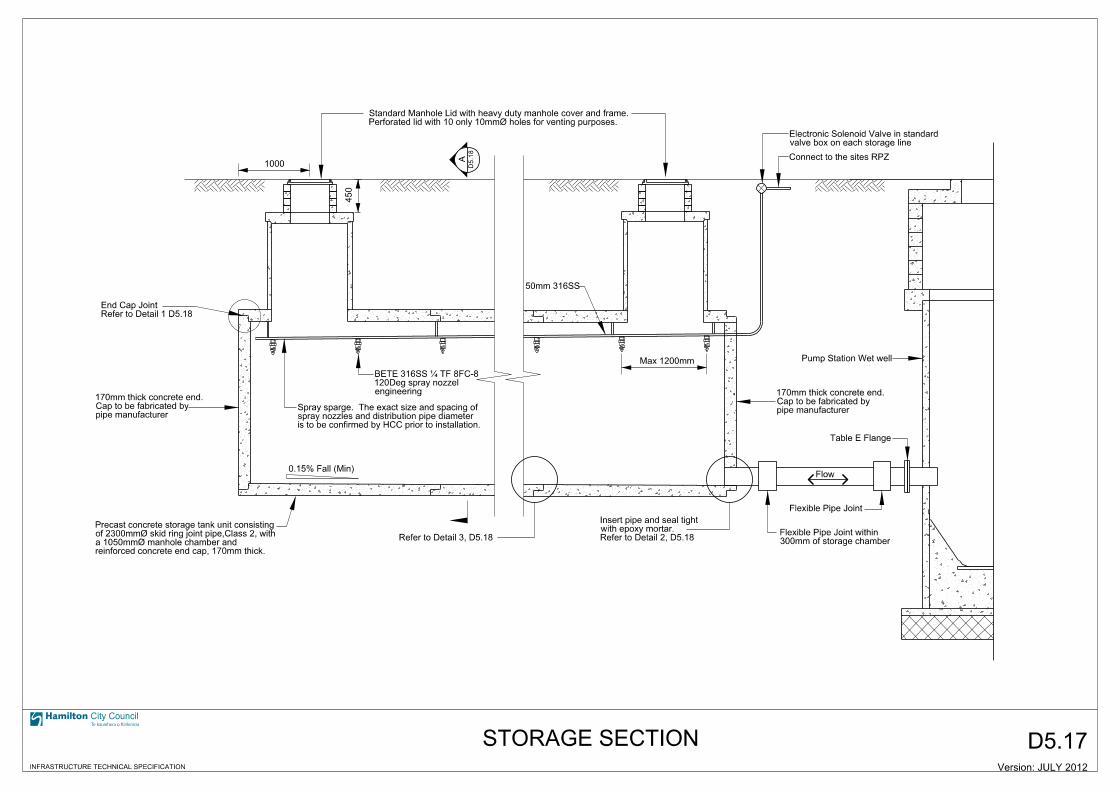
pipe manufacturerCap to be fabricated by170mm thick concrete end.
reinforced concrete end cap, 170mm thick.a 1050mmØ manhole chamber and of 2300mmØ skid ring joint pipe,Class 2, with Precast concrete storage tank unit consisting
is to be confirmed by HCC prior to installation.spray nozzles and distribution pipe diameter Spray sparge. The exact size and spacing of
1000
450
0.15% Fall (Min)
pipe manufacturerCap to be fabricated by170mm thick concrete end.
Table E Flange
Pump Station Wet well
Flow
Flexible Pipe Joint
300mm of storage chamberFlexible Pipe Joint within
valve box on each storage lineElectronic Solenoid Valve in standard
Perforated lid with 10 only 10mmØ holes for venting purposes.Standard Manhole Lid with heavy duty manhole cover and frame.
Connect to the sites RPZ
Max 1200mm
50mm 316SS
STORAGE SECTION
Refer to Detail 3, D5.18
engineering120Deg spray nozzel BETE 316SS … TF 8FC-8
Refer to Detail 2, D5.18with epoxy mortar.Insert pipe and seal tight
D5.1
8
Refer to Detail 1 D5.18End Cap Joint
D5.17
City Council
INFRASTRUCTURE TECHNICAL SPECIFICATION
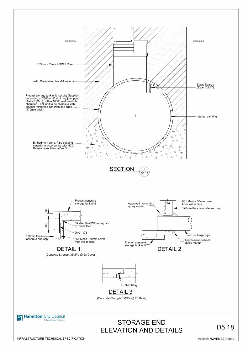
1050mm Class 2 RCFJ Riser
Insitu Compacted backfill material
Development Manual Vol 3.
material in accordance with HCC
Embedment zone. Pipe bedding
300
60
storage tank unit
Precast concrete
to inside face
Sikaflex Pro3WF (or equal)
D10 - 175
from inside face
661 Mesh - 50mm coverconcrete end cap
170mm thick
DETAIL 1(Concrete Strength 35MPa @ 28 Days)
epoxy mortar
Approved non-shrink
storage tank unit
Precast concrete epoxy mortar
Approved non-shrink
Discharge pipe
170mm thick concrete end cap
from inside face
661 Mesh - 50mm cover
DETAIL 2
DETAIL 3
(Concrete Strength 35MPa @ 28 Days)
Skid Ring
SECTION A
(170mm thick).
precast reinforced concrete end caps
chamber. Tank unit to be complete with
Class 2 (Min.), with a 1050mmØ manhole
consisting of 2300mmØ skid ring joint pipe,
Precast storage tank unit (cast by Supplier),
Internal painting
D5.17
ELEVATION AND DETAILS
STORAGE END
City Council
INFRASTRUCTURE TECHNICAL SPECIFICATION Version: NOVEMBER 2012
D5.18
(Refer D5.17)
Spray Sparge

1
2
3
4
5
6
1 2 3
4 65
SECTION
200
200
200
100 350 350 100
225 200 350
200
100
300
500
100
200
200 Varies (Determined by Cabinet)100 100
50
100
Mowing Strip
D10 (All round)
R6 Ties @ 150mm Centres
PLAN
CONCRETE CONTROL CABINET PLINTH(Concrete Strength 35 MPa @ 28 days)
100mmØ PVC Duct - Pump Power
100mmØ PVC Duct - Floats/Level Sensors
50mmØ PVC Duct - Flow Meter
100mmØ PVC Duct - Power Inlet
’Y’ Junction
Concrete Thrust Block
(Min)
5x Pipe Ø
(Min)
2x Pipe Ø
Flo
w
Flow Meter
FLOW METER INSTALLATION DETAILS
A
CABLE DUCTS
(If remotly installed)50mmØ PVC Duct - Overflow Float
A
180
D10 (All round)
R6 Ties @ 150mm Centres
80mm Clearance (Min)
D5.19SPS FLOW METER CONTROL CABINET PLINTH
(If any sparges installed)50mmØ PVC Duct - Solenoid Valves
380
230
guide linesto manufactures installation flow meter nominated bore Internal Diameter to match
guide linesto manufactures installation flow meter nominated bore Internal Diameter to match
free of fittings or bendsStraight section of pipe
(Min)
80mm Clearance
City Council
INFRASTRUCTURE TECHNICAL SPECIFICATION Version: NOVEMBER 2012
Plynth to be designed to meet soil conditions
NOTES:
1450
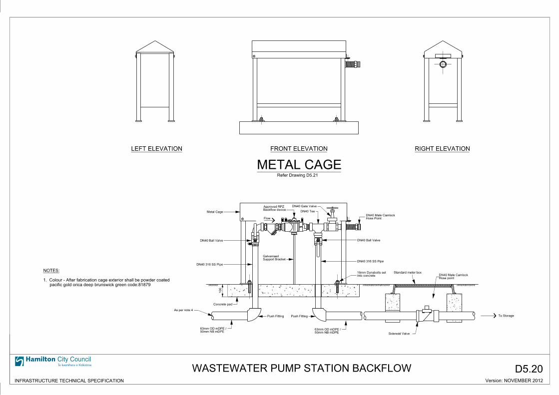
D5.20
METAL CAGE
LEFT ELEVATION FRONT ELEVATION RIGHT ELEVATION
Backflow deviceApproved RPZ DN40 Gate Valve
DN40 Tee
Flow
DN40 Ball Valve
Support BracketGalvanised
Hose PointDN40 Male Camlock
into concrete16mm Dynabolts set Standard meter box
Hose pointDN40 Male Camlock
100
Concrete pad
50mm NB mDPE63mm OD mDPE /
Push Fitting
50mm NB mDPE63mm OD mDPE /
Push Fitting
Metal Cage
Refer Drawing D5.21
To Storage
Solenoid Valve
As per note 4
City Council
INFRASTRUCTURE TECHNICAL SPECIFICATION
WASTEWATER PUMP STATION BACKFLOW
pacific gold orica deep brunswick green code:81879
1. Colour - After fabrication cage exterior shall be powder coated
NOTES:
DN40 Ball Valve
DN40 316 SS Pipe
DN40 316 SS Pipe
Version: NOVEMBER 2012
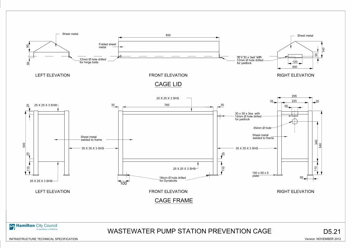
50
90
Sheet metal
metalFolded sheet
850 Sheet metal
for padlock12mm Ø hole drilled30 x 30 x 3ea. with
for hinge bolts12mm Ø hole drilled
50
140
120
300
RIGHT ELEVATIONFRONT ELEVATIONLEFT ELEVATION
CAGE LID
540
110
25
25
LEFT ELEVATION FRONT ELEVATION RIGHT ELEVATION
CAGE FRAME
25 X 25 X 3 SHS
25 X 25 X 3 SHS
35 X 35 X 3 SHS 35 X 35 X 3 SHS
25 X 25 X 3 SHS
25 X 25 X 3 SHS
for Dynabolts18mm Ø hole drilled
100
110
25
35 35765
for padlock12mm Ø hole drilled30 x 30 x 3ea. with
45mm Ø hole
welded to frameSheet metal
plate100 x 50 x 5
295
225
50
35 35
50
110
340
540
welded to frameSheet metal
D5.21
City Council
INFRASTRUCTURE TECHNICAL SPECIFICATION Version: NOVEMBER 2012
WASTEWATER PUMP STATION PREVENTION CAGE