TYPES SC. SCl. SV AND SV-1 RELAYS . com · TYPES SC. SCl. SV AND SV-1 RELAYS I. L. 41-766 ... I...
20
TYPES SC. SCl. SV AND SV-1 RELAYS __________ ___ _ P"NtL LOC,.TIOM OR PRO:CTION TYPE MTG -- 1�0�32 TERM. SCR(W U�E .1,0 -3Z TUD FOR THICK PANEL MIG 1 t'·l I F D.,. : J II U : I 6'-- I ' ' II -- 6 PANEL LOC . TION OR � OIA.. HOLE DRILL PER IHT(RN,L SCHEMATIC FOR PROJE.CT\ON MT� ON \HICK PAHEL5 STUDS roR PRO TYPE MTG. � D\A HOLE (z REQ.). CUT OUT FOR 5E MI -FLUSH � OIA. HOLES FOR SEMI LUSH TYPE. MTG. ( 4OLES} . .. -· .... . . '• - .� ) SEMI LU$ H TYPE MTG.. WITH $CREW __ _ 24 W STUD ---18 q. STUD ( 2 REQ.) 16-B-2740 Fig. 10-0utline And Drilling Plan The Relays In The S-10 Semi-Flush Or Projection Type Flexitest Case. See The Inteal Schematic For The Terminals Supplied. For Reference Only. N-331622 Fig. 11-View Of Type SC Relay Showing Correct Shaping Of Moving Contact Leads. and the t op of should be 3/1 6 " Both contacts the core. This dimension on the SV-1 relay f or A-C. should touch at the same t ime when the plunger is raised. When the plunger is moved upward against its stop , there should be a slight deflection of the s ta t i on ary contact stop springs, but this should not ex- c e ed 1/32". When the stationary contacts are reversed so that they are closed when the re - lay is de-energized, they should be located so that they jugt touch the moving contacts when the latter are 1/32" above the de-energized position. On some relays it may be f ound that when the contacts are used in this position the relay may operate at values a ew percent below the sca le markings. The ad j u stment s specified for the stationary contacts are im- portant. Fa ilure to observe them may cause improper relay operation, after a period of service. either directly or Contact position should not be used as a means of altering the ratio of dropout to pickup. RENEWAL PARTS Repair work can be done most satisfactorily at the fa c t ory. However, interchangeable parts can be furnished to the customers who are equipped for doing repair work. When ordering parts, always give the complete name- plate data. WESTINGHOUSE ELECTRIC CORPORATION METER DIVISIO N • N EWARK, N.J. • www . ElectricalPartManuals . com
Transcript of TYPES SC. SCl. SV AND SV-1 RELAYS . com · TYPES SC. SCl. SV AND SV-1 RELAYS I. L. 41-766 ... I...
TYPES SC. SCl. SV AND SV-1 RELAYS _____________ _
P"Nt.L LOC,..TIOM F"OR PRO..II::CTION TYPE MTG ------._
�--------::0
1�0�32. TERM. SCR(W
U�E .1,0 -3Z. !JTUD FOR
THICK PA.NE.L MIG
11 t'·l I F D.,. : J II U :
I 6'-- I YF' fD" ' II -- 6 I> _______j
PA.NEL LOC ..... TION F"OR
� OIA.. HOLE. DRILL PE.R IHT(RN,...L SCHEMATIC FOR PROJE.CT\ON MT� ON \HICK PA.HE.L5
STUDS roR PRO,J. TYPE MTG. � D\A HOLE. (z REQ.).
CUT OUT FOR 5EMI -FLUSH
� :i OIA. HOLES FOR SE.MI F"LUSH TYPE. MTG. (4-HOLE.S} . f-----. .. -1 -· .....
. '• -.� ) SE.M.I f"LU$ H TYPE MTG.. 2:1: WITH $CREW ___ __j 24 Wl"n-4 STUD )_ --i\-18 MTq. STUD ( 2 REQ.) 16-B-2740
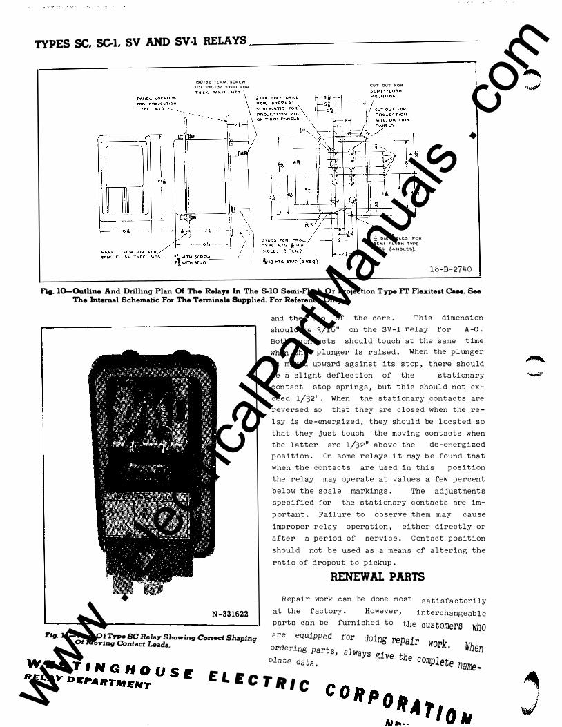
Fig. 10-0utline And Drilling Plan Of The Relays In The S-10 Semi-Flush Or Projection Type FT Flexitest Case. See The Internal Schematic For The Terminals Supplied. For Reference Only.
N-331622
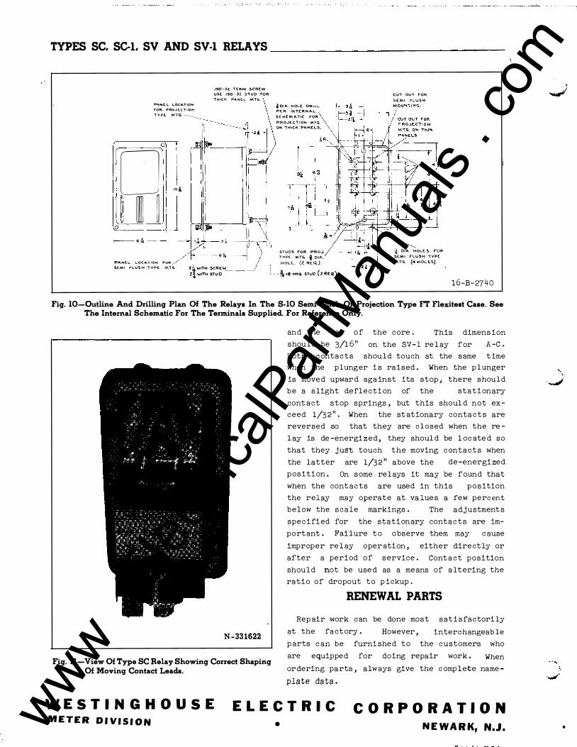
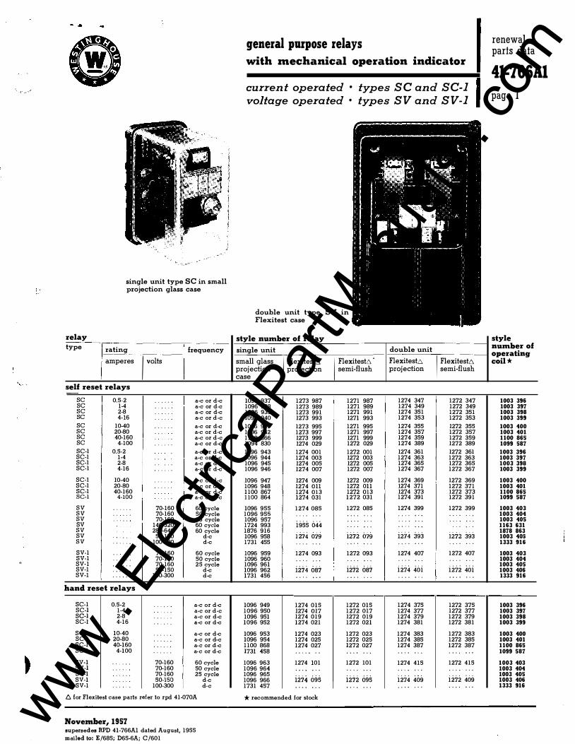
Fig. 11-View Of Type SC Relay Showing Correct Shaping Of Moving Contact Leads.
and the top o f
should be 3/1 6 "
Both conta c t s
the core. This d imens ion
on the SV-1 relay f or A-C.
should touch at the same t ime
when the plunger i s ra ised. When the plunger
is moved upward aga inst its stop , there should
b e a slight deflection of the sta t i onary
conta ct stop springs, but this should not ex
ceed 1/32" . When the stationary conta c t s are
reversed so that they are closed when the re
l ay is de-energiz ed, they should be l ocated so
that they jugt touch the moving conta c t s when
the latter are 1/32" above the d e-energized
p os ition . On s ome relays it may be f ound that
when the conta c t s are used in this p o s ition
the relay may operate at value s a :few percent
below the s cale markings. The ad justment s
specifi ed for the stationary conta c t s are im
portant. Failure t o observe them may cause
improper relay operation,
after a period o f s ervice.
either d ire ctly or
Conta c t position
should not be used as a means of alt ering the
ratio of dropout to p ickup.
RENEWAL PARTS
Repair work can be done most sat i s factorily
at the fa ct ory. However, interchangeable
parts can be furni shed to the customers who
are equipped for doing repair work. When
ord ering parts, always give the c omp l ete name
plate data.
WESTINGHOUSE ELECTRIC CORPORATION METER DIVISION • NEWARK, N.J. • www .
Elec
tricalP
artM
anua
ls . c
om
f' .._
e
c
TYPES SC. SCl. SV AND SV-1 RELAYS I. L. 41-766
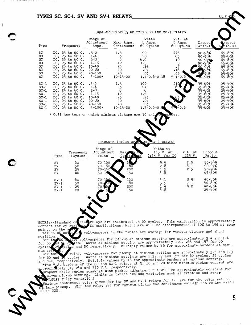
CHARACTERISTICS OF TYPES SC AND SC-1 RELAXS
Range of Watts V.A. at
Type Adjustment Max. Amps. 5 Amps. 5 Amps. Dropout Dropou t
Frequency Amps. Continuous 60 Cycles 60 Cycles Ratio-AC Ratio-De
sc DC, 25 to 60 c. -5-2 1.5 99 225 90-98% 65-80% sc DC, 25 to 60 c. 1-4 3 28 65 90-98% 65-80% sc DC, 25 to 60 c. 2-8 6 6.9 19 90-98% 65-80% sc DC, 25 to 60 c. 4-16 12 1.5 5 90-98% 65-80% sc DC, 25 to 60 c. 10-40 25 .24 -7 90-98% 65-80% sc DC, 25 to 60 c. 20-80 40 .07 .16 90-98% 65-80% sc DC, 25 to 60 c. 40-160 40 .03 .05 90-98% 65-80% sc DC, 25 to 60 c. 4-100* 10-15-20 1.7-0.6-0.18 5-1-0.2 90-98% 65-80%
SC-1 DC, 25 to 60 c. .5-2 1.5 100 210 35-60% 25-40% SC-1 DC, 25 to 60 c. 1-4 3 24 60 35-60% 25-40% SC-1 DC, 25 to 60 c. 2-8 6 6 16 35-60% 25-40% SC-1 DC, 25 to 60 c. 4-16 12 1.5 5 35-60% 25-40% SC-1 DC, 25 to 60 c. 10-40 25 .25 .65 35-60% 25-40% SC-1 DC, 25 to 60 c. 20-80 40 .07 .16 35-60% 25-40% SC-1 DC, 25 to 60 c. 40-160 40 .03 .05 35-60% 25-40% SC-1 DC, 25 to 60 c. 4-100* 10-15-20 1.7-0.6-0.18 5-1-0.2 35-60% 25-40%
* Coil has taps on vhich minimum pickups are 10 and 30 ampere s.
CHARACTERISTICS OF SV AND SV-1 RELAYS
Range of Watts at Frequency A dju stment Max. Volt s 115 V . AC V.A . .at Dropout
Type ( Cycle s Volts Continu ou s {125 v. for DC 115 v. Ratio
sv 60 70-160 160 3-4 7-3 90-98% SV 50 70-160 180 2.8 6.1 90-98% sv 25 70-160 200 1.5 2.5 90-98% SV DC 50-150 150 4.8 65-80%
SV-1 60 70-160 160 4.1 8 . 5 40-80% SV -1 50 70-160 180 3-5 7-1 40-80% SV-1 25 70-160 200 1.4 3-2 40-80% SV-J DC 50-150 150 4.8 25-40%
NOTES:--S tan dard current relays are c alibrated on 60 cycl e s. Thi s calibration i s approximat ely
c orrect for 25 cyc l e an d DC app lic ati on s, but there will b e di screpanci e s of 10% to 15% at some
point s on the scale. V alue s of wat t s an d vol t-amp ere s in the tab l e s are average for vari ous plunger an d shunt
p osition. For tne SC relay, vol t-amp eres. for pickup at minimum setting are approximately 3.4 and 1.4
for 60 an d 25 cycle s. Watts at minimum s etting are approximately 1.0, .65 an d .57 for 60
cyc l e s, 2 5 cycl e s an d DC respectively. Mul tiply value s by 1 6 for approximate burdens at maxi-
mum setting. For the SC-1 rel ay, volt-ampere s for pickup at minimum setting are approximately 3-5 an d 1.3
for 60 and 25 cycles. Watts at minimum setting s ar e 1.3, .7 and -57 for 60 cycles, 25 cyc l e s
an d d-e, respectively. Multiply valu e s by 16 for approximate burden s a t maximum set ting.
*The V.A. burden s of the SC and SC-1 relays at 3, 10 and 20 times minimum pickup current are
approximately 31, 240 and 770 V.A. respectively.
Dropout ratio varies s omewhat with pickup adjus tment but will be approximately c ons tant for
any given pickup setting. Limits in tab l e s include variab l e s such as friction an d other
individual relay variations. Maximum c ontinuou s vole s given for the SV and SV-1 relays for A-C are for the relay set ford
i k With the r elay set for maximum pickup th e continuous voltage can be increase minimum p c up .
10 to 20%. 5
www . El
ectric
alPar
tMan
uals
. com
TYPES SC. SC-1. SV AND SV-1 RELAYS
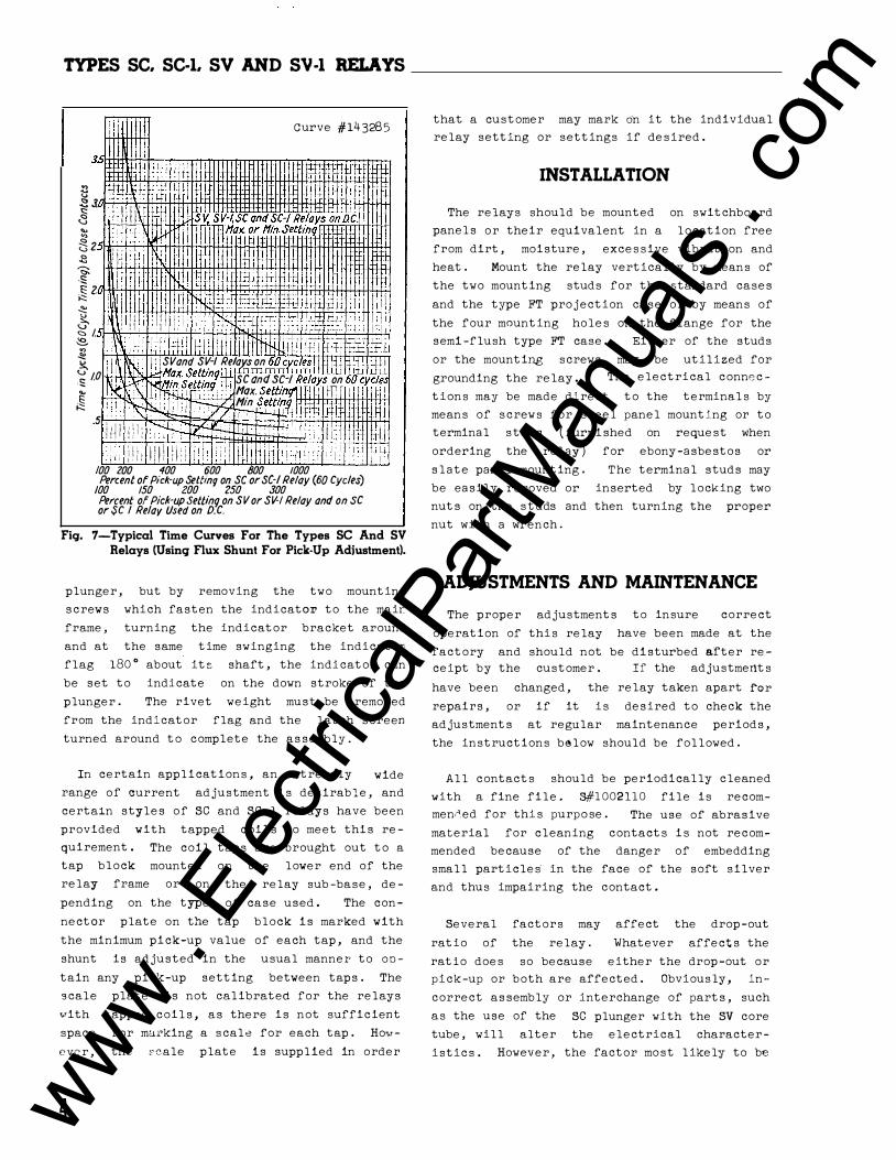
: ) Curve #143285
3..,
� , p 11 11m , _fi '+i �J t ' lltt . .§ I Ill- I i cSV.SV-I,SCandSC-IRelaysonD.C .. �2 .ll!fJi � tiHIIl1l Wtax.orHin.settinq fl
� � iii ii11 !'K dJII t � !Pi !tlrlfi �!It �z i !Ill Hill! lliih ·
1 , t I � I. ! ! 11 ! II ! : H rP !i H , H � >� ll!!ii1liiW11HI�I�rnttmn1kmitt 1+!:1 M .;) .... I !j :� � l'iSVand SV-1 Relays on 60cvc es lf .j I c 01 td\N.. •;.;,11ax. Settinq1ffi11mlm=nrn;;:l;- _ 1 it Ll ·!::: I. 111; f:I..X"M-,wn Settin 1 SC and SC-I Relays on 60 c�f(f "' II'('[\ . \II !li-Fii. 1 nY1: il l'f<?X. Sett!n�i_l-fffi W f I I� II ! � ill' ¥1'\..l : IIIII I fT!t1--b4.i: Htn. Set�mff I . jil �1:1:1 rt li:J: . 111 !'�1::4.< · , . "/� 1fi' f+ fj.:f-t H 111-ltl - c) !ii
.S iII I ! ! 1 : iihmf-� N I J] lilltl! i t J li ���� ilit 1:11 :1:1 i:ti li!i a fi tllll'iillllff 1 H 100 zoo 400 600 800 1000 Percent of Pick-up Settin'l on SC or SC-I Relay (60 Cycles)
/00 !50 zoo 250 300 Percent of Pick-upSettinq on SVor SV-1 Relay and on SC or SC I Relay Used on D.C.
Fig. 7-Typical Time Curves For The Types SC And SV Relays (Using Flux Shunt For Pick-Up Adjustment).
plunger, but by removing the two mounting
screws which fasten the indicator to the mair
frame, turning the indicator bracket arounc
and at the same time swinging the indicator·
flag 180° about its shaft, the indicator can
be set to indicate on the down stroke of the
plunger. The rivet weight must be removed
from the indicator flag and the latch screen
turned around to complete the assembly.
In certain applications, an extremely wide
range of current adjustment is desirable, and
certa�n styles of SC and SC-1 relays have been
provided with tapped coils to meet this re-
quirement.
tap block
The coil taps are brought out to a
mounted on the lower end of the
relay frame or on
pending on the type
the relay sub-base, de
of case used. The con-
nectar plate on the tap block is marked with
the minimum pick-up value of each tap, and the
shunt is adjusted in the usual manner to Obtain any pick-up setting between taps. The
scale plate is not calibrated for the relays
vith tapped coils, as there is not sufficient
space for marking a scale for each tap. Ho•r
evcr, the 2cale plate is supplied in order
4
that a customer may mark on it the individual
relay setting or settings if desired.
INSTALLATION
The relays should be mounted on switchboard
panels or their equivalent in a location free
from dirt, moisture, excessive vibration and
heat. Mount the relay vertically by means of
the two mounting studs for the standard cases
and the type FT projection case or by means of
the four mounting holes on the flange for the
semi-flush type FT case. Either of the studs
or the mounting screws may be utilized for
grounding the relay. The electrical connec-
tions may be made direct to the terminals by
means of screws for steel panel mounting or to
terminal studs (furnished on request when
ordering the relay) for ebony-asbestos or
slate panel mounting. The terminal studs may
be easily removed or inserted by locking two
nuts on the studs and then turning the proper
nut with a wrench.
ADJUSTMENTS AND MAINTENANCE
The proper adjustments
operation of this relay
to insure correct
have been made at the
factory and should not be disturbed after receipt by the customer. If the adjustments
have been changed, the relay taken apart �or
repairs, or if it is desired to check the
adjustments at regular maintenance periods,
the instructions below should be followed.
All contacts should be periodically cleaned
with a fine file. 3#1002110 file is recom-
men�ed for this purpose. The use of abrasive
material for cleaning contacts is not recom
mended because of the danger of embedding
small particles· in the face of the soft silver
and thus impairing the contact.
Several factors may affect the drop-out
ratio of the relay. Whatever affects the
ratio does so because either the drop-out or
pick-up or both are affected. Obviously, in
correct assembly or interchange of parts, such
as the use of the SC plunger with the SV core
tube, will alter the electrical character
istics. However, the factor most likely to be
www . El
ectric
alPar
tMan
uals
. com
TYPES SC. SCI. SV AND SV-1 RELAYS _______________ ____c:__l.=--l. 4-'-'-1-'------76::.::.6
9-D-8313
CONTAC� EITHER �OR. BREAk: AS REQUtRED.
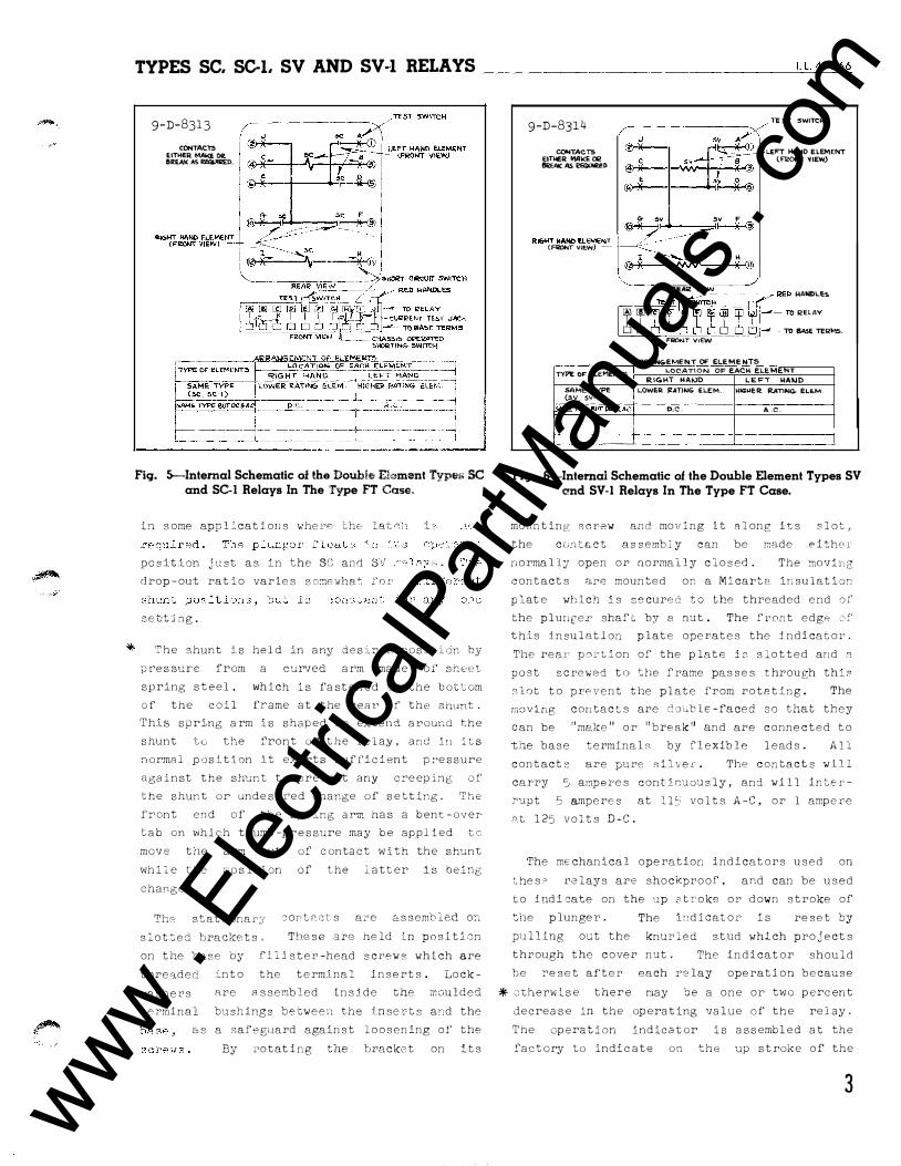
Fig. >.-Internal Schematic oi !he Double Element Type.:• SC and SCI Relays In The Type FT Case"
in some appl�_cations wher8 c;hs lat<;:l L
position j ttst as in the SC and sv drop-out ratio varies somewha� for
set-ting�
'�he shunt ls held in any des'Lrecl_ pos:ition by
pressure from a curved arm made of sheet spring steel, which is fastened to the bott om
of the coil frame at the rear of the shunt. This spring arm is shaped to extend around the
shunt tc the front of' the re1ay, and ln its normal position lt ex erts sufricient pr'essure
against the shunt to prevent any creep ing of the shunt or undesired change of setting. The front end of the spring arm has a bent-over
tab on which thumb-pr essure may be applied to move the arm out of contact with the shunt
while the p osition of the latter is being changed.
Th,_:;; statJ.onary
slot�ed brackets�
cont2cts are assembled on
These are held in position
on the base by fil1ster-head screws which are
threaded into the terminal i nserts. Lock-
9-D-8314 TEST :SWITCH
COt4TACT5 EITHEI:l MA�E a2 �EAIC:AS�D
J =
,.,.,c � E �
:# SV .(3) 1' 2-·�
6- �V SV F
LEFT HAND ELEMENT lFli!ON> �lEW)
� �� ·-��·-,�s CFRONr VIEW) - I :sv H
� ------R.EA'! VIEW
� � f¥ 11; %f�: :AE:�Es
6 6 CJ 6 _.____ TO BAsE TEI>Ms. FQONT VIEW AR�NG-EMEN.T OF ELEMENTS
TYPE OF ELEMENTS LOCATION OF EACH EL..EMENT RIG>'T HAIVO SAME TYPE ! \..OWER. JZATING ELEM. (sv, SV-ll
SAMETVPEBVTPC.A.AC.! D.C. f-'-'---- I c-----+ '------ - -- ___________j_
LEF\ WMJO H\Gt.IER. �NG- EL6..M
A.c.
Fig. 6-Intemal Schematic of the Double Element Types SV end SV-1 Relays In The Type FT Case.
mo11nting screw and moving it Along its slot, the ccJntEJ,ct assembJ.y can be rnade either
normally open or normally closed . The mo vin g contacts n�e mounted on a Micarta ir1sulation
plate -which is secured to the threaded end or the plunge r shaft by a nut . The front edge ::,f' this insulation plate operates the indicator.
The rear portion of the plate is slotted and n p o st screwed to the frame passes through this
slot to prevent the plate from rotating. The
moving contacts are doGble-faced so that they
can be "me.ke" or "break'' and are connected to
the base terminals by flexible leads. All
contacts are pure silver. The contacts will
carry 5 amperes contif.)uously_, an8. will i nter
Y''-lpt 5 amperes at ll�; volts A-C, or l ampere
�t 125 volts D-C.
The mechanical operation i ndicators used on
ches� l'elays are shockproof, and can be used
to indicate on the �p 3Croke or down stroke of
:.he plunger.
pulling out the
The indicator is reset by
knUl'led stud which projects
through the cover nut . The indicator should
be reset after each relay operation because
washers are assembled inside the moulded * otherwise there may be a one or two percent terminal bushings between the inser t s and the
as a safeguard against loosening of the
By rotat i ng the bracket on its
decrease in the operating value of the relay.
The operation indicator is assembled at the
factory to indicate on the up stroke of the
3 www . El
ectric
alPar
tMan
uals
. com
TYPES SC. SCI. SV AND SV-1 RELAYS _____________ _
I I I I I ' \__ ___ _)
Front View
Terminal
Stationary Contact
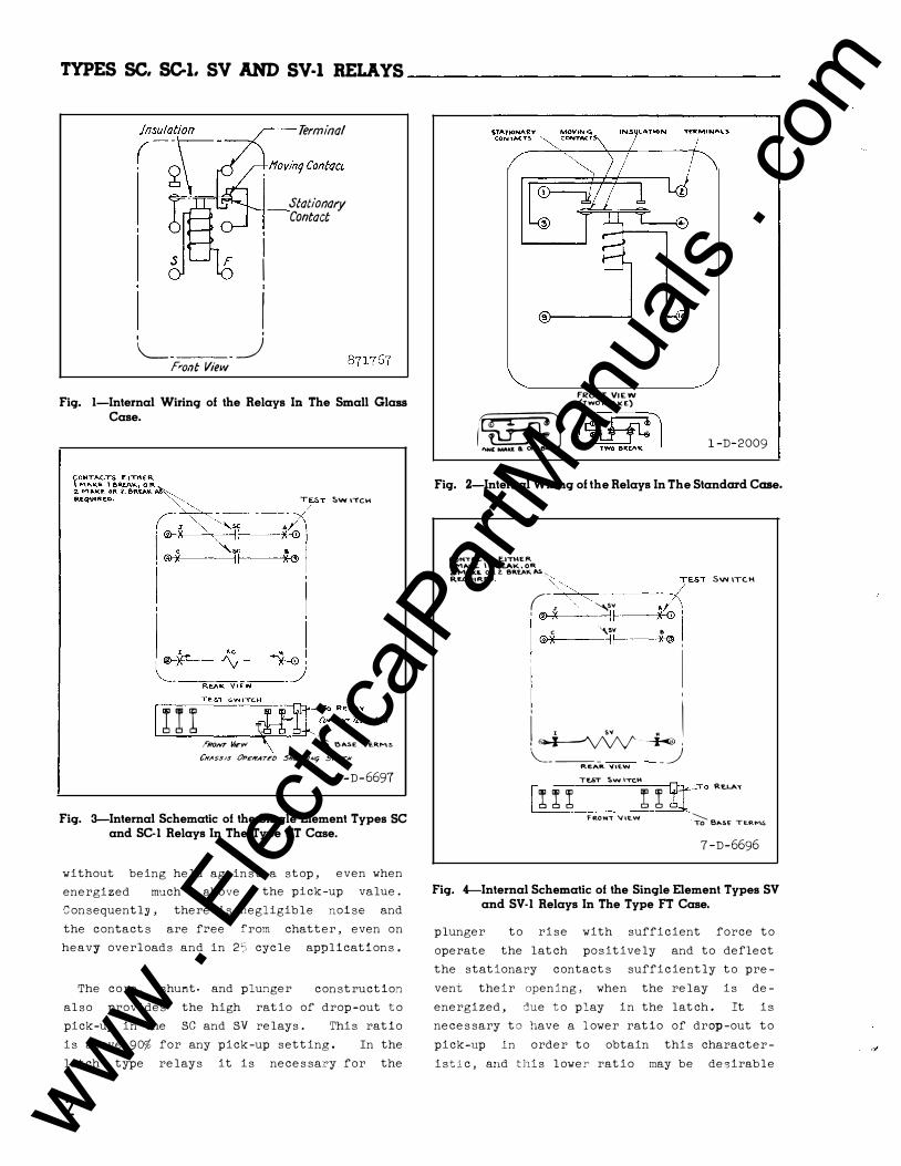
Fig. 1-Internal Wiring of the Relays In The Small Glass Case.
::,wrTCH
I I I I �-ftf=:R;:�;;T dACK FRONT vJFw \ To eA.s.E \E.R.Ms
CH�SS/S (}pEJiiATFD 5HO.f'T/Aitj SwncN 7-D-6697
Fig. 3-Internal Schematic of the Single Element Types SC and SC-1 Relays In The Type FT Case.
without being held against a stop, even when
energized much above the pick-up value.
Consequently, there is negligible noise and
the contacts are free from chatter, even on
heavy overloads and in 2'i cycle applications.
The core, shunt. and plunger construction
also provides the high ratio of drop-out to
pick-up in the SC and SV relays. This ratio
is above 90% for any pick-up setting. In the
latch type relays it is necessa:ry for the
2
fRONT VIEW (TWO MAKE)
r�J (�JA�l 1-D-2009
Fig. 2-Intemal Wiring of the Relays In The Standard Case.
C.0NT,...,C.TS EJTH.E.R \ MA.KE \ 8R.E.A.K,OR Z..MAKE. OR l. 81\EA\1(, loS, R£.QUIRE.D. "� .-JEST SWITC.H (-
;r , ', <::: "'sv /� ' ® X llf-----,X)(-0 'I c '\SV & @X Ii-I --*X® ,
I ' i I sv M I . � 1 \___ _ _ ___) REA.R. V\E.W I I I I TUT �WITCHI I
rr-TO RUA�
fROM,- 'IIE.W ·---...._ TO BAS£ TERM� 7-D-6696
Fig. 4-Internal Schematic of the Single Element Types SV and SV-1 Relays In The Type FT Case.
plunger to rise with sufficient force to
operate the latch positively and to deflect
the stationary contacts sufficiently to pre
vent their opening, when the relay is de
energized, due to play in the latch. It is
necessary to have a lower ratio of drop-out to
pick-up in order to obtain this character
istic, and this lower ratio may be desirable
www . El
ectric
alPar
tMan
uals
. com
� � .. ".·
l.l. 41-766
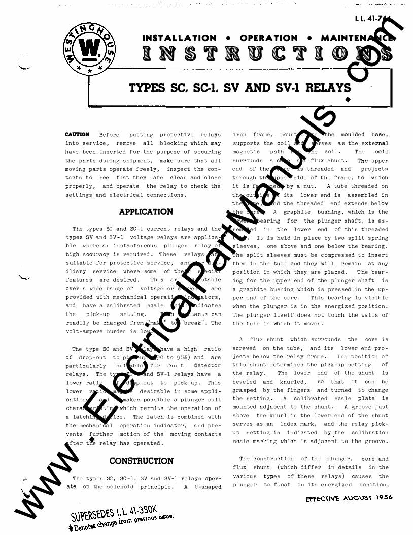
INSTALLATION • OPERATION • MAINTENANCE
INSTRUCTIONS TYPES SC, SC-1, SV AND SV-1 RELAYS
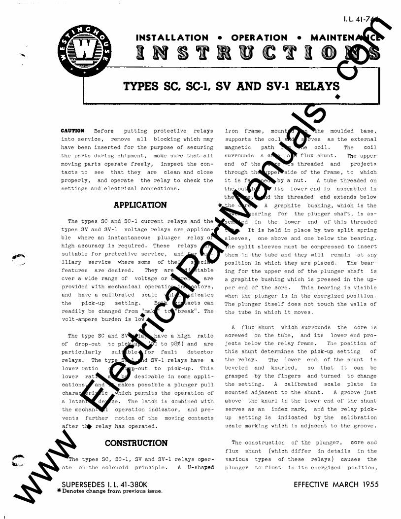
CAUTION Before putting protective relays
into service, remove all blocking which may
have been inserted for the purpose of securing
the parts during shipment, make sure that all
moving parts operate freely, inspect the con
tacts to see that they are clean and close
properly, and operate the relay to check the
settings and electrical connections.
APPLICATION
The types SC and SC-1 current relays and the
types SV and SV-1 voltage relays are applica
ble where an instantaneous plunger relay of
high accuracy is required. These relays are
suitable for protective service, and for aux
iliary service where some of their special
features are desired. They are adjustable
ever a wide range of voltage or current, are
provided with mechanical operation indicators,
and have a calibrated scale which indicates
the pick-up setting. Both contacts can
readily be changed from "make" to "break". The
volt-ampere burden is low.
The type SC and SV relays have a high ratio
of drop-out to pick-up (90 to 98%) and are
particularly suitable for fault detector
relays. The type SC-1 and SV-1 relays have a
lower ratio of dron-out to pick-up. This
lower ratio may be desirable in some appli
cations, and it makes possible a plunger pull
characteristic which permits the operation of
a latching device. The latch is combined with
the mechanical operation indicator, and pre
vents further motion of the moving contacts
after the relay has operated.
CONSTRUCTION
The types SC, SC-1, SV and SV-1 relays oper
ate on the solenoid principle. A U-shaped
SUPERSEDES I. L. 41-380K *Denotes change from previous issue.
iron frame, mounted on the moulded base,
supports the co�l and serves as the external
magnetic path for the coil.
surrounds a core and flux shunt.
The coil
The upper
end of the core is threaded and projectR
through the upper side of the frame, to which
it is fastened by a nut. A tube threaded on
the outside at its lower end is assembled in
the core, and the threaded end extends below
*the core. A graphite bushing, which is the
lower bearing for the plunger shaft, is as
sembled in the lower end of this threaded
tube. It is held in place by two split spring
sleeves, one above and one below the bearing.
The split sleeves must be compressed to insert
them in the tube and they will remain at any
position in which they are placed. The bear
ing for the upper end of the plunger shaft is
a graphite bushing which is pressed in the up
per end of the core. This bearing is visible
when the pluhger is in the energized position.
The plunger itself does not touch the walls of
the tube in which it moves.
A flux shunt which surrounds the core is
screwed on the tube, and its lower end pro
jects below the relay frame. J'he position of
this shunt determines the pick-up setting of
the relay. The lower end of the shunt is
beveled and knurled, so that
grasped by the fingers and turned
the setting. A calibrated scale
it can be
to change
plate is
mounted adjacent to the shunt. A groove just
above the knurl in the lower end of the shunt
serves as an index mark, and the relay pick
up setting is indicated by .the calibration
scale marking which is adjacent to the groove.
The construction of the plunger, core and
flux shunt (which differ in details in the
various types of these relays ) causes the
plunger to float in its energized position,
EFFECTIVE MARCH 1955 www . El
ectric
alPar
tMan
uals
. com
--� '
• ,_
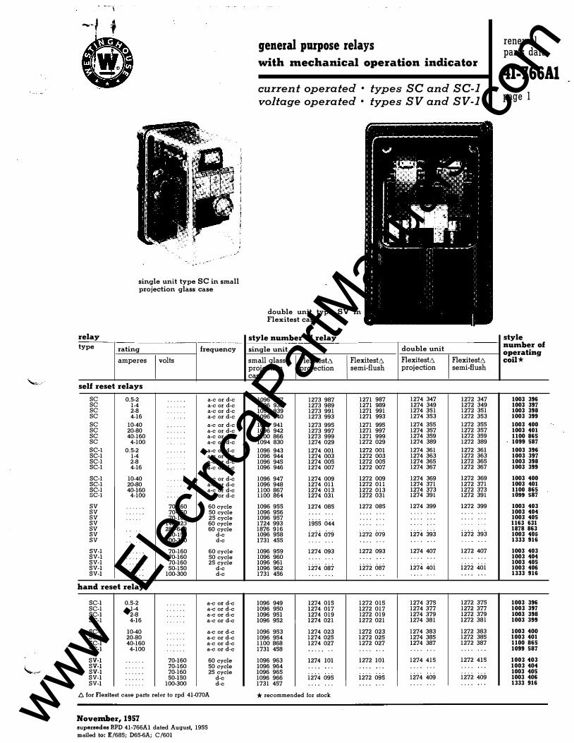
single unit type SC in small projection glass case
relay type rating frequency
amperes
I volts
self reset relays
sc 0.5-2 . . . . . a-cor d-e sc 1-4 . . . . . . a-cor d-e sc 2-8 . . . . . . a-cor d-e sc 4-16 a-cor d-e
sc 10-40 . . . . . . a-cor d-e sc 20-80 . .. .. a-cor d-e sc 40-160 . . . . . a-cor d-e sc 4-100 . . a-cor d-e
SC-1 0.5-2 . . . a-cor d-e SC-1 1-4 a-cor d-e SC-1 2-8 . . a-cor d-e SC-1 4-16 ... . . a-cor d-e
SC-1 10-40 a-cor d-e SC-1 20-80 a-cor d-e SC-1 40-160 a-cor d-e SC-1 4-100 . . . . . . a-cor d-e
sv . .. . . 70-160 60 cycle sv . . . . . . 70-160 50 cycle sv . . . . . 70-160 25 cycle SV 140-320 60 cycle sv 280-640 60 cycle sv 50-150 d-e sv .. 100-300 d-e
SV-1 . . . . . . 70-160 60 cycle SV-1 . . . . . 70-160 50 cycle SV-1 . .. ... 70-160 25 cycle SV-1 · · · · · · 50-150 d-e SV-1 .. . .. . 100-300 d-e
hand reset relays
SC-1 0.5-2 . . . . . . a-cor d-e SC-1 1-4 · · · · · · a-cor d-e SC-1 2-8 . . . . . a-cor d-e SC-1 4-16 .. . . . . a-cor d-e
SC-1 10-40 . . . . . . a-cor d-e SC-1 20-80 . . . . . a-cor d-e SC-1 40-160 . . . . . a-cor d-e SC-1 4-100 . . . . a-cor d-e
SV-1 . . . .. . 70-160 60 cycle SV-1 . .. . . . 70-160 50 cycle SV-1 . . . . . . 70-160 25 cycle SV-1 . . . . . . 50-150 d-e SV-1 . . ... . 100-300 d-e
!::. for Flexi!est case p arts refer to rpd 41-070A
November, 1957 supersedes RPD 41-766A1 d ated August, 1955
mailed to: E/685; D65-6A; C/601
general purpose relays with mechanical operation indicator
current operated • types SC and SC-1 voltage operated • types SV and SV-1
double unit type SV in Flexitest case
style number of relay
single unit
small glass projection case
1096 937 1096 938 1096 939 1096 940
1096 941 1096 942 1100 866 1094 830
1096 943 1096 944 1096 945 1096 946
1096 947 1096 948 1100 867 1100 864
1096 955 1096 956 1096 957 1724 993 1876 916 1096 958 1731 455
1096 959 1096 960 1096 961 1096 962 1731 456
1096 949 1096 950 1096 951 1096 952
1096 953 1096 954 1100 868 1731 458
1096 963 1096 964 1096 965 1096 966 1731 457
I Flexi!es!2. projection
1273 987 1273 989 1273 991 1273 993
1273 995 1273 997 1273 999 1274 029
1274 001 1274 003 1274 005 1274 007
1274 009 1274 011 1274 013 1274 031
1274 085 . . . . . . . . . . . . . . 1955 044
1274 679 . . . . . . .
1274 093 . . . . ... .
. . .
. . . 1274 087 . . . . . . .
1274 015 1274 017 1274 019 1274 021
1274 023 1274 025 1274 027 . . .. . . .
1274 101 . . . . . . . . . . . . . . 1274 095 . . . . . . .
* recommended for stock
I Flexites!6 semi-flush
1271 987 1271 989 1271 991 1271 993
1271 995 1271 997 1271 999 1272 029
1272 001 1272 003 1272 005 1272 007
1272 009 1272 011 1272 013 1272 031
1272 085 . .. . . . . . . . . .
. . .
. . .
. . .
i272 o79 . . . . . . .
1272 093 . . . . . . ..
. . .
. . . 1272 087 . . .. . . .
1272 015 1272 017 1272 019 1272 021
1272 023 1272 025 1272 027 . . . . . . .
1272 101 . . . . . . . .
. . .
. . . 1272 095 . . . . . . .
double unit
Flexites!6 projection
1274 347 1274 349 1274 351 1274 353
1274 355 1274 357 1274 359 1274 389
1274 361 1274 363 1274 365 1274 367
1274 369 1274 371 1274 373 1274 391
1274 399 . . . . . . . . . . . . . . ..
. . .
. . .
. . .
. . 1274 393 . . . . . . .
1274 407 . . . . . .. .
. . .
. . . 1274 401 . . .. . . .
1274 375 1274 377 1274 379 1274 381
1274 383 1274 385 1274 387 . . . . . . .
1274 415 . . . . .. ..
. . .
. . . 1274 409 . . . . . . .
I Flexites!6 semi-flush
1272 347 1272 349 1272 351 1272 353
1272 355 1272 357 1272 359 1272 389
1272 361 1272 363 1272 365 1272 367
1272 369 1272 371 1272 373 1272 391
1272 399 . . . . . . .. . .. .
. . .
. ..
. . .
1272 393 . .. . . . .
1272 407 . . . . . . . .
. . .
. . . 1272 401 . . . . . . .
1272 375 1272 377 1272 379 1272 381
1272 383 1272 385 1272 387 . . . . . . .
1272 415 . . . . . . . .
. . .
. .. 1272 409 . . . . . . .
renewal paris dafa
41-766Al page I
style number of operating coil *
1003 396 1003 397 1003 398 1003 399 1003 400 1003 401 1100 865 1099 587 1003 396 1003 397 1003 398 1003 399 1003 400 1003 401 1100 865 1099 587 1003 403 1003 404 1003 405 1163 631 1878 863 1003 406 1333 916 1003 403 1003 404 1003 405 1003 406 1333 916
1003 396 1003 397 1003 398 1003 399 1003 400 1003 401 1100 865 1099 587 1003 403 1003 404 1003 405 1003 406 1333 916
www . El
ectric
alPar
tMan
uals
. com
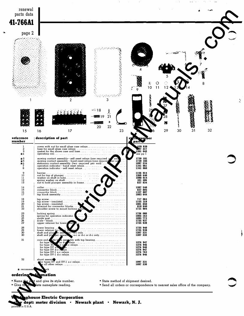
renewal parts data
41-766Al page 2
1 5 I
1 6
2
1 8 �d- 1 9 """'X-
20 1 7
=
re
=
fe
=
r
=
e
=
n
:..
c
_
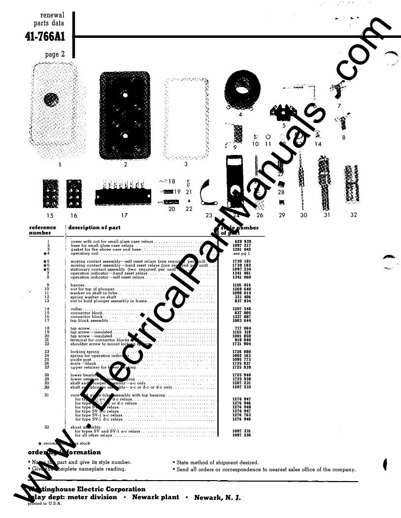
e __ [ description of part number
1 cover with nut for small glass case relays . . . 2 base for small glass case relays. 3 gasket for the above case and base .
*4 operating coil . . .
3
11 L 21 �
22 23
*5 moving contact assembly--self reset relays (one required per unit) . *5 moving contact assembly-hand reset relays (one required per unit) . *6 stationary contact assembly (two required per unit) .
7 operation indicator-hand reset relays . . 8 operation indicator-self reset relays .
9 10 11 12 13
14 15 16 17
18 19 20 21 22
23 24 25 26 27
28 29 30 30
31
32
barrier. . . . . . . . . . . . . nut for top of plunger . washer on shaft in tube . spring washer on shaft . . . . . . . . . . . . . . . nut to hold plunger assembly in frame .
collar . . . . connector block . . . . connector block ..... . tap block assembly . . .
tap screw . . . . . . . . . . . . . . tap screw-insulated . . . . tap screw-insulated . terminal for connector blocks . shoulder screw to mount locking spring .
locking spring . . . . . . . . . . . . . . spring for operation indicator . guide post . . . . . . . . . . . . . . . . . . scale -blank . . . . . . . . . . . . . . . . . upper retainer for lower bearing .
lower bearing . . . lower retainer for lower bearing . . . . . shaft and plunger assembly-a-c only . . . . . . . . . . . . . . . . shaft and plunger assembly-a-c or d-e or d-e only . . . .
core and guide tube assembly with top bearing . . . . for type SC a-c or d-e relays . for type SC-1 a-c or d-e relays . for type SV a-c relays . . . . for type SV d-e relays . . for type SV -1 a-c relays . for type SV -1 d-e relays . . . . . . . . . . . .
shunt assembly . . . . . . . . . . . . . . . . . . for types SV and SV-1 a-c relays . . for all other relays .
* recommended for stock
ordering information
4
1 0
I 25
24 26
style number of part
629 939 1097 217 1201 042 see pg 1
1730 181 1730 182 1097 234 1341 061 1341 060 1156 014 1269 640 1098 014 321 406 837 934 1207 540 837 80S 1337 887 1003 644 717 064 1155 319 1001 850 818 840 1731 904
1726 080 1002 163 1095 773 1725 937 1725 939 1725 940 1725 938 1207 231 1207 232
1276 947 1276 946 1276 948 1276 947 1276 763 1276 946
1097 231 1097 230
• Name the part and give its style number. • State method of shipment desired.
�-
�
• 6 7
11/1'
1' 5
0 8 1 1 1 2 1 3 1 4
II 27
• 28
• 29 30 3 1 32
• Give the complete nameplate reading. • Send all orders or correspondence to nearest sales office of the company.
Westinghouse Electric Corporation
relay dept: meter division Newark plant • Newark, N. J. printed i n U.S.A.
'•
t •
www . El
ectric
alPar
tMan
uals
. com
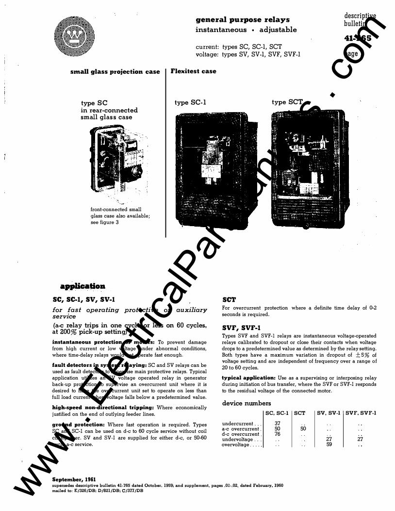
general purpose relays instantaneous • adjustable
descriptive bulletin
41-765 current: types SC, SC-1, SCT voltage: types SV, SV-1, SVF, SVF-1 page I
small glass projection case
type SC in rear-connected small glas s case
front-connected small glass case also available; see figure 3
appUc:atioa SC, SC-1, SV, SV-1
Flexitest case
type SC-I
for fast operating protective or auxiliary service {a-c relay trips in one cycle or less on 60 cycles, at 200% pick-up setting)
instantaneous protection of motors: To prevent damage from high current or low voltage under abnormal conditions, where time-delay relays would not operate fast enough.
fault detectors in system relaying: SC and SV relays can be used as fault detectors to supervise main protective relays. Typical application utilizes an SV voltage operated relay in generator back-up protection to supervise an overcurrent unit where it is desired to have the overcurrent unit set to operate on less than full load current when voltage falls below a predetermined value.
high-speed non-directional tripping: Where economically justified on the end of outlying feeder lines.
ground protection: Where fast operation is required. Types SC and SC-1 can be used on d-e to 60 cycle service without coil
changeover. SV and SV-1 are supplied for either d-e, or 50-60 cycle a-c service.
September, 1961
type SCT
SCT For overcurrent protection where a definite time delay of 0-2 seconds is required.
SVF, SVF-1 Types SVF and SVF-1 relays are instantaneous voltage-operated relays calibrated to dropout or close their contacts when voltage drops to a predetermined value as determined by the relay setting. Both types have a maximum variation in dropout of ±5% of voltage setting and are independent of frequency over a range of
20 to 60 cycles.
typical application: Use as a supervising or interposing relay during initiation of bus transfer, where the SVF or SVF-1 responds to the residual voltage of the connected motor.
device numbers
SC, SC-I SCT
undercurrent . .. a-c overcurrent . d-e overcurrent . undervoltage . . . overvoltage .. . . .
37 50 76
50
SV, SV-1 SVF, SVF-1
27 59
27
supersedes descriptive bulletin 41-765 dated October, 1959; and supplement, pages .01-.02, dated February, 1960
mailed to: E/326/DB; D/821/DB; C/377/DB www . El
ectric
alPar
tMan
uals
. com
page 2
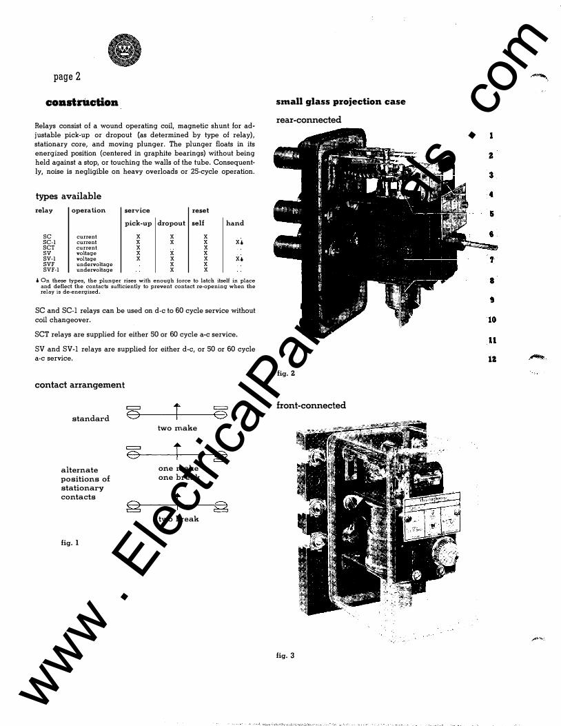
coast ruction Relays consist of a wound operating coil, magnetic shunt for adjustable pick-up or dropout {as determined by type of relay), stationary core, and moving plunger. The plunger floats in its energized position {centered in graphite bearings) without being held against a stop, or touching the walls of the tube. Consequently, noise is negligible on heavy overloads or 25-cycle operation.
types available
relay operation service reset
pick-up dropout self hand
sc current X X X SC-1 current X X X x• SCT current X X sv voltage X X X SV-1 voltage X X X x. SVF undervoltage X X SVF-1 undervoltage X X
i On these types, the plunger rises with enough force to latch itself in place and deflect the contacts sulliciently to prevent contact re-opening when the relay is de-energized.
SC and SC-1 relays can be used on d-e to 60 cycle service without coil changeover.
SCT relays are supplied for either 50 or 60 cycle a-c service.
SV and SV-1 relays are supplied for either d-e, or 50 or 60 cycle a-c service.
contact arrangement
= r standard 0 = 0
two make
= r 0 alternate one make positions of one break stationary contacts + §
two break
fig. 1
small glass projection case
rear-connected
tz fig. z
front-connected
fig. 3
www . El
ectric
alPar
tMan
uals
. com
general purpose relays instantaneous • adjustable
descriptive bulletin
41-765 current: types SC, SC-1, SCT voltage: types SV, SV-1, SVF, SVF-1 page 3
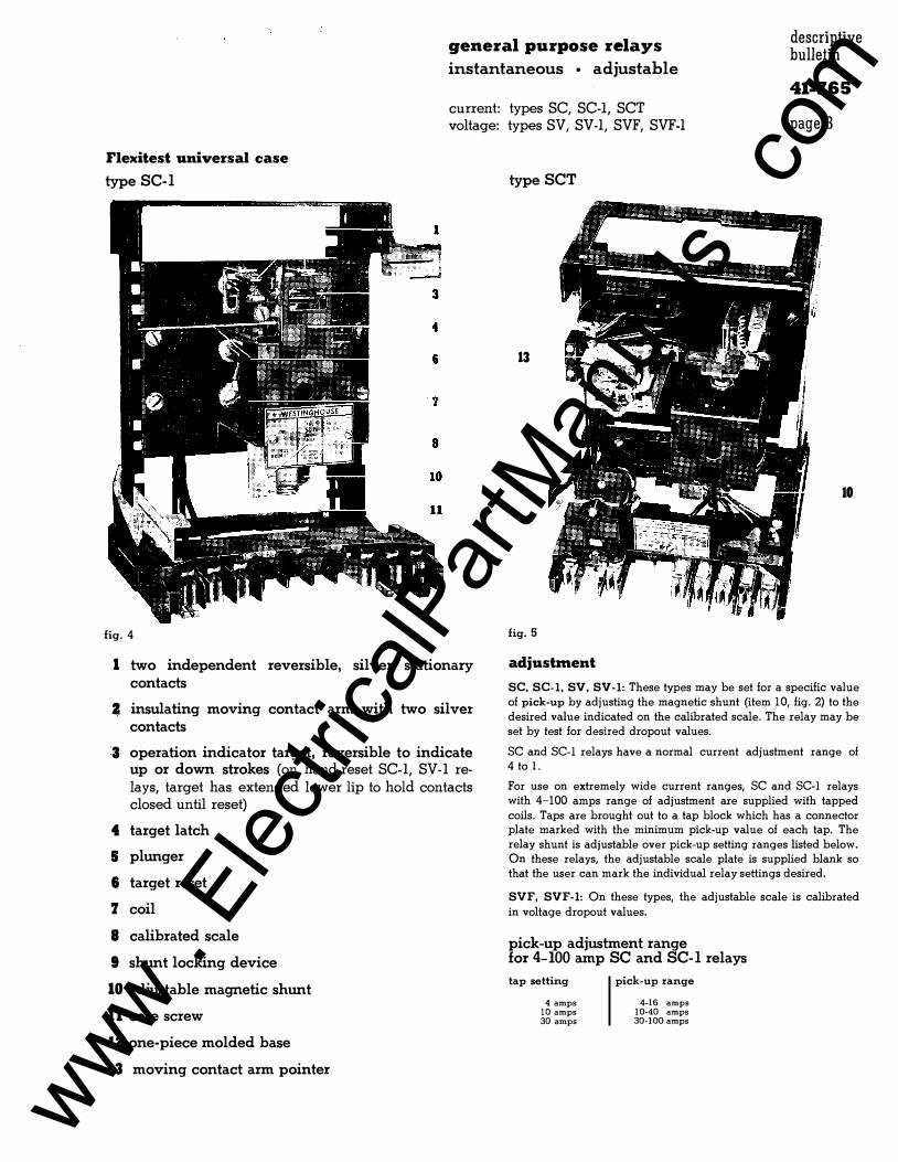
Flexitest universal case
type SC-I
fig. 4
1 two independent reversible, silver stationary contacts
2 insulating moving contact arm with two silver contacts
3 operation indicator target, reversible to indicate up or down strokes (on hand-reset SC-1, SV-1 re
lays, target has extended lower lip to hold contacts closed until reset)
4 target latch
5 plunger
6 target reset
7 coil
8 calibrated scale
9 shunt locking device
10 adjustable magnetic shunt
11 core screw
12 one-piece molded base
13 moving contact arm pointer
type SCT
13
10
fig. 5
adjustment
SC, SC-1, SV, SV-1: These types may be set for a specific value of pick-up by adjusting the magnetic shunt (item 10, fig. 2) to the desired value indicated on the calibrated scale. The relay may be set by test for desired dropout values.
SC and SC-I relays have a normal current adjustment range of 4 to l.
For use on extremely wide current ranges, SC and SC-I relays with 4-IOO amps range of adjustment are supplied with tapped coils. Taps are brought out to a tap block which has a connector plate marked with the minimum pick-up value of each tap. The relay shunt is adjustable over pick-up setting ranges listed below. On these relays, the adjustable scale plate is supplied blank so that the user can mark the individual relay settings desired.
SVF, SVF-1: On these types, the adjustable scale is calibrated
in voltage dropout values.
pick-up adjustment range for 4-100 amp SC and SC-I relays
tap setting
4 amps 10 amps 30 amps
pick-up range
4-16 amps 10-40 amps 30-100 amps
www . El
ectric
alPar
tMan
uals
. com
page 4
consbuction continued
specific SCT data
SCT relays are available in 10-40 ampere range, with 0-120 cycle (60 cycle base) time delay.
construction and operation
A type SC current unit is combined with a synchronous motor timing unit, which is actuated by a small saturating transformer.
The motor drives a moving contact arm (through a gear train) over a semi-circular arc. A pointer on the arm indicates the time delay on a calibrated scale at the top of the timer unit.
The synchronous motor has a floating rotor which is in mesh with the gear train only when energized. The rotor falls out of mesh instantly upon de-energization, permitting a spring to reset the moving contact arm.
adjustment
The SC instantaneous current unit is adjusted by setting the magnetic shunt (item 10, figure 5) to the desired value. The unit may also be set by test for a desired dropout value.
Time delay is adjusted by setting the moving contact arm pointer to the desired value on the calibrated scale (item 13, figure 5).
As the timing motor is controlled by the instantaneous unit contact, the trip circuit will not be energized until the timing unit has completed its timing cycle.
case
SCT relays are supplied in the FT-21 Flexitest universal case.
specific SVF, SVF-1 data
SVF and SVF-1 relays are available in single- or three-phase designs.
The single-phase design is used on balanced, three-phase applications whereas the three-phase type is recommended for applications where one or more of the phase voltages may be unbalanced by a fault on the system.
construction and operation
single-phase: Single-phase types consist of an SV or SV-1 voltage unit, a reactor, series resistor, and a full-wave rectifier. Insensitivity to frequency is obtained by operating the voltage unit on full-wave, rectified a-c voltage. The reactor in the a-c circuit is used to compensate for the tendency of the voltage unit to respond to the instantaneous voltage values and, as a result, drop out at higher r. m. s. values. The reactor causes the rectified current in the voltage unit to increase slightly as the frequency decreases, thereby maintaining a dropout value of approximately the same r. m. s. voltage over a 20 to 60 cycle frequency range.
The series resistor in the operating coil circuit minimizes the effect of relay coil temperature variation.
three-phase: Three-phase types consist of an SV or SV-1 voltage unit, a series resistor, and a three-phase bridge rectifier.
adjustment
The scale on both single- and three-phase types is calibrated in voltage drop-out values; 24 to 36 volts for type SVF, and 30 to 45 volts for the SVF -1.
A typical value of pick-up voltage for the SVF relay is 95 volts for a 45-volt dropout setting. A similar value for the SVF-1 is 100 volts for a 36-volt dropout setting.
Both types are designed for a nominal 120-volt system.
case
SVF and SVF-1 relays are available in the FT-21 Flexitest universal case only.
motor transfer schemes
On motor transfer schemes, the three-phase SVF or SVF-1 relay senses the magnitude of residual voltage in a motor, and allows transfer of the motor to an alternate supply source when the residual voltage has decreased to a value determined by the selected dropout voltage setting of the relay.
www . El
ectric
alPar
tMan
uals
. com
•
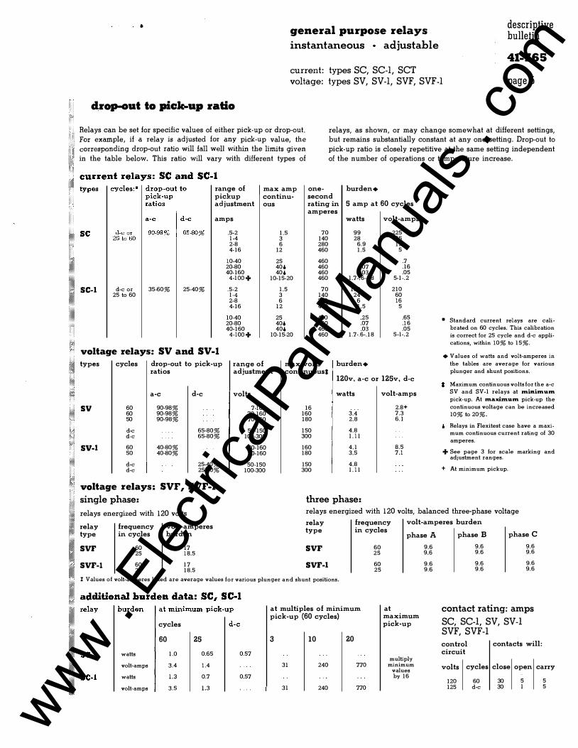
drop-out to pick-up ratio
general purpose relays instantaneous adjustable
current: types SC, SC-I, SCT voltage: types SV, SV-I, SVF, SVF-I
descriptive bulletin
41-765 page 5
Relays can be set for specific values of either pick-up or drop-out.
.. ' .... '.,'
.,• ... '.,.: .... '.,' .. ,.. ���r:::=���g
i�r:p�::y r!:io
a��;t��l ::lt:th��c7�:pli:���i:�=
. in the table below. This ratio will vary with different types of
relays, as shown, or may change somewhat at different settings, but remains substantially constant at any one setting. Drop-out to
pick-up ratio is closely repetitive at the same setting independent of the number of operations or temperature increase.
range of max amp one- burden+ pickup continu- second adjustment ous rating in 5 amp at 60 cycles
amperes amps watts volt-amps
SC-1 d-e or 25 to 60
35-60% 25-40%
voltage relays: SV and SV-1
types cycles
� sv 60 60 50
d-e d-e
drop-out to pick-up ratios
a-c d-e
90-98% 90-98% 90-98%
65-80% 65-80%
60 40-80% 50 40-80%
d-e 25-40% d-e 25-40% � :::age •elays• svr, SVF-1
[)}] single phasex
.5·2 1.5 70 99 l -4 3 140 28 2-8 6 280 6.9 4-16 12 460 1.5
10-40 25 460 .24 20-80 406 460 .07 40-160 406 460 .03
4-lOO+ 10-15-20 460 1.7-.6-.18
.5-2 1.5 70 100 l -4 3 140 24 2-8 6 280 6 4-16 12 460 1.5
10-40 25 460 .25 20-80 406 460 .07 40-160 406 460 .03
4-lOO+ 10-15-20 460 1.7-.6-.18
range of adjustment
max volts burden+ continuous I
225 65 19
5
.7
.16
.05 5-l -.2
210 60 16
5
.65
.16
.05 5-l-.2
120v, a-c or 125v, d-e
volts watts volt-amps
7-16 16 2.8+ 70-160 160 3.4 7.3 70-160 180 2.8 6.1
50-150 150 4.8 100-300 300 l . l l
70-160 160 4.1 8.5 70-160 180 3.5 7.1
50-150 150 4.8 100-300 300 l . l l
three phasex
• Standard current relays are cali
brated on 60 cycles. This calibration
is correct for 25 cycle and d-e appli
cations, within 10% to 15%.
• Values of watts and volt-amperes in
the tables are average for various
plunger and shunt positions.
Maximum continuous volts for the a-c
SV and SV-1 relays at rninimum pick-up. At maxhnum pick-up the
continuous voltage can be increased
10% to 20%.
Relays in Flexitest case have a maximum continuous current rating of 30
amperes.
+ See page 3 for scale marking and adjustment ranges.
+ At minimum pickup.
�!!1!!! relays energized with 120 volts relays energized with 120 volts, balanced three-phase voltage
relay frequency volt-am peres type in cycles burden
relay frequency volt-amperes burden type in cycles
phase A phase B phase C
SVF 60 17 25 18.5
SVF 60 9.6 9.6 9.6 25 9.6 9.6 9.6
SVF-1 60 l 7 25 18.5
SVF-1 60 9.6 9.6 9.6 25 9.6 9.6 9.6
I Values of volt-amperes listed are average values for various plunger and shunt positions. � ::itio:'!d
�•d:� m
"::;
::�m
��:.
s.:� cycles
60 25
watts 1.0 0.65 0.57
volt-amps 3.4 1.4
watts 1.3 0.7 0.57
volt-amps 3.5 1.3
at multiples of minimum pick-up (60 cycles)
3 10 20
31 240 770
31 240 770
at maximum pick-up
multiply minimum
values by 16
contact rating: amps
SC, SC-I, SV, SV-I SVF, SVF-1
control circuit
contacts will:
volts cycles close open carry
120 125
60 d-e
30 30
5 l
5 5
www . El
ectric
alPar
tMan
uals
. com
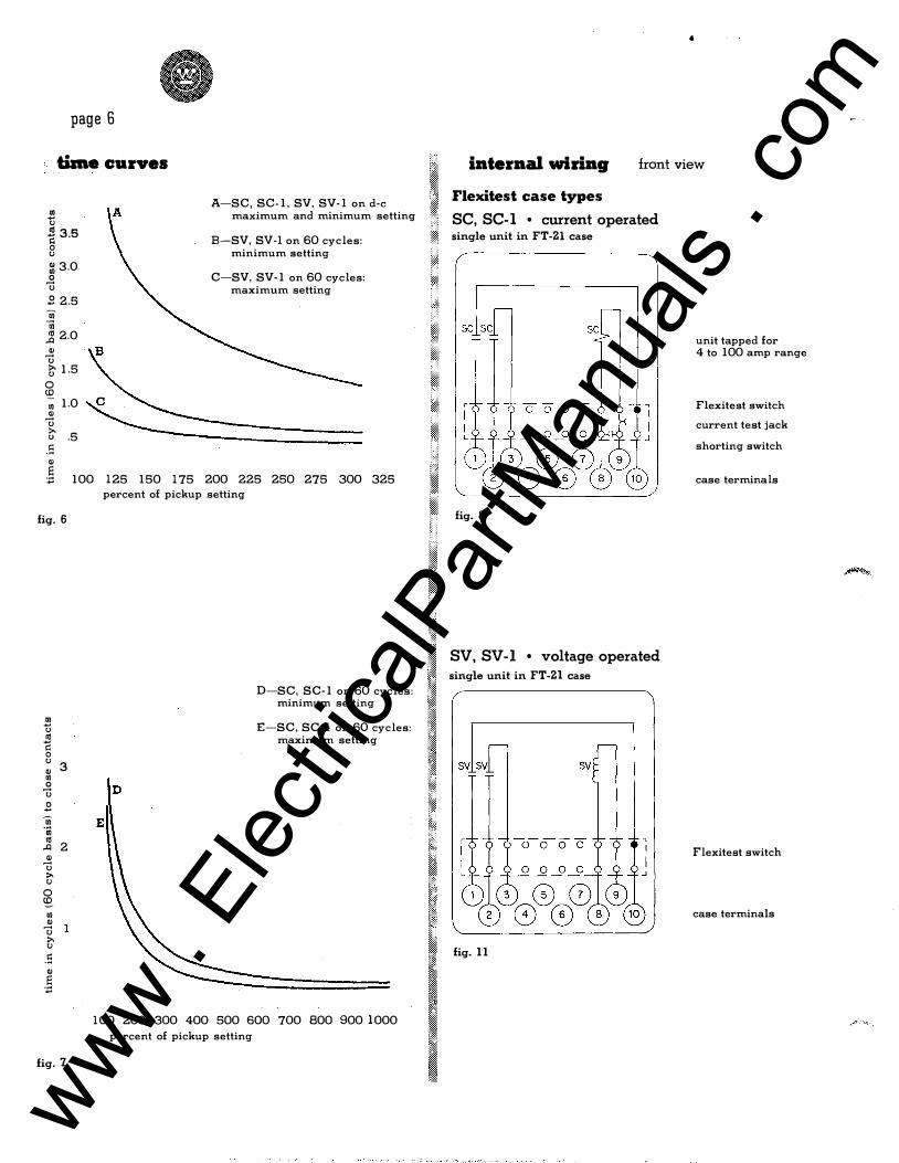
page 6
time curves 2l " � 3.5 0 " � 3.0 0
u .8 2.5 Ui "iii � 2.0 "
u � 1.5 0 <0 -; 1.0 " u G' .5 .s "
A-SC, SC-1, SV, SV-1 on d-e maximum and minimum setting
B-SV, SV-1 on 60 cycles: minimum setting
C-SV, SV-1 on 60 cycles: maximum setting
] 100 125 150 175 200 225 250 275 300 325
fig. 6
2l " <1l -;: 0 " 3 " Ul 0 u .8 Ui "iii <1l 2 ..Q "
u >-" 0 cg Ul "
u >-" .s " ]
fig. 7
percent of pickup setting
D
E
D-SC, SC-1 on 60 cycles: minimum setting
E-SC, SC-1 on 60 cycles: maximum setting
100 200 300 400 500 600 700 800 900 1000 percent of pickup setting
•
internal wiring front view
Flexitest case types
SC, SC-I • current operated single unit in FT -Zl case
fig. 8
SV, SV-1 • voltage operated single unit in FT-Zl case
fig. 11
unit tapped for 4 to 100 amp range
Flexitest switch
current test jack
shorting switch
case terminals
Flexitest switch
case terminals
www . El
ectric
alPar
tMan
uals
. com
' ,.
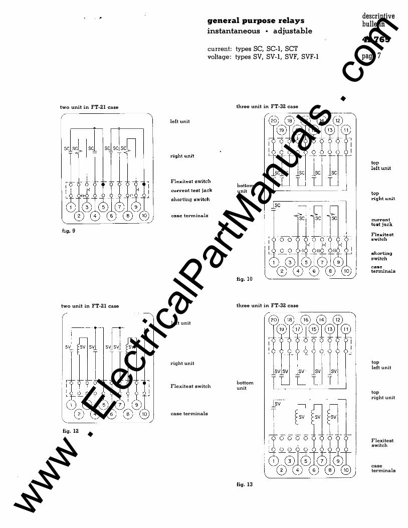
two unit in FT-21 case
two unit in FT-21 case
fig. 12
left unit
left unit
right unit
general purpose relays instantaneous • adjustable
current: types SC, SC-1, SCT
voltage: types SV, SV-1, SVF, SVF-1
three unit in FT -32 case
three unit in FT-32 case
Flexitest switch bottom unit
case terminals
fig. 13
descriptive bulletin
41-765 page 7
top left unit
top right unit
Flexitest switch
case terminals
www . El
ectric
alPar
tMan
uals
. com
descriptive bulletin
41-765 general purpose relays
page 8 types SC, SC-1, SCT, SV, SV-1, SVF, SVF-1
front view
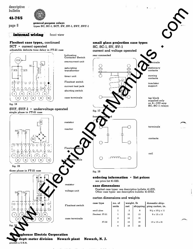
Flexitest case types, continued SCT • current operated adjustable definite time delay in FT-21 case
fig. 14
Indicating Contactor Switch
overcurrent unit
saturating transformer
timer unit
Flexitest switch
current test jack
shorting switch
case terminals
SVF, SVF-1 • undervoltage operated single phase in FT-21 case
resistor
reactor
Flexitest switch
case terminals
fig. 15
three phase in FT-21 case
resistor
voltage unit
lo � Flexitest switch
" '
small glass projection case types
SC, SC-I, SV, SV-1 current and voltage operated
rear connected
fig. 17
front connected
fig. 18
terminals
stationary contacts
moving contacts
insulator support
tap block supplied only on 4-100 amp SC, SC-I relays
terminals
contacts
coil
ordering information • list prices see price list 41-020.
case dimensions Flexitest case types: see descriptive bulletin 41-075. Other case types: see descriptive bulletin 41-075A.
carton dimensions and weights
case type
small glass
Flexitest: FT-21
no. of
units
weight, lb
net shipping
2 6
10 13
domestic ship-
ping carton, in.
9Y, X lOY, X ll
9 x l2 x l3
case terminals 2 12 15
FT-32 3
fig. 16 4
Westinghouse Electric Corporation
relay dept: meter division Newark plant Newark, N. J . printed i n U.S.A.
15 19 13 X 13 X 21
18 22
www . El
ectric
alPar
tMan
uals
. com
I. L. 41-766
INST A L LATION • OPERATION • MAINTENANCE
INSTRUCTIONS TYPES SC. SCI. SV AND SV-1 RELAYS
CAUTION Bef ore put t ing protective relays
block ing which may int o servi ce, remove all
have been inserted f o r the purpose of securing
the parts during shipment, make sure that all
moving parts operate f re ely, inspe ct t he con
tacts t o see that they are clean and close
pr operly, and operate the relay t o che ck the
se t t ings and ele ctrical c onne c t i ons.
APPLICATION
The types SC and SC-1 current relays and the
types SV and SV-1 voltage relays are applica
ble where an instantaneous plunger relay of
high accuracy is required. These relays are
suitable f o r p r o t e c t ive service, and f o r aux
iliary se r v i c e where some of the i r spe cial
features are desi red. They are adjustable
ever a wide range of volt age or current, are
provided with me chanical ope ra t i on indicat o rs,
and have a calibrat ed scale which indicates
the pick-up sett ing . Both contact s can
readily be changed f r om " mak e " to "break " . The
volt-ampere burden is low .
The t ype SC and SV relays have a high rat i o
o f drop - out t o p i ck -up ( 9 0 t o 9 8% ) and ar'e
part i cu larly suitab l e f o r fau l t d e t e c t o r
relays. The type SC-1 and SV-1 relays have a
lower rat i o of drop-out t o pick-up. This
lower rat i o may be desi rable in some appli
cati ons, and it makes possible a plunger pull
charac t e rist i c which permits the ope rat i on of
a lat ching device. The latch is c ombined with
the mechanical ope rat ion indi cat o r, and pre
vents further mot i on of the moving c ontacts
aft e r the relay has operated.
CONSTRUCTION
The types SC, SC-1, SV and SV-1 relays oper
ate on the solenoid princ iple. A U-shaped
i r on f rame, m ounted on the moulded base ,
supports the c o il and
magnet i c path f o r
serves a s the external
t he c o il.
surr ounds a c o r e and flux shunt.
The coil
The upper
end of the c o re is threaded and projects
through the upper side of the f rame, to which
it is fastened by a nut. A tube threaded on
the outside at its lower end is assembled in
the c ore, and the t hreaded end extends below
*the c ore . A graph i t e bushing, which is the
l ower bearing f or the plunger shaft , is as
sembled in the lower end of this threaded
tube. It is held in place by t wo spli t spring
sle e v es, one above and one below the bearing.
The spli t sleeves must be c ompressed t o insert
t hem in the tube and they will remain at any
p osit ion in whi ch they are pla c e d. The bear
ing f or the upper end of the plunger shaft is
a graphite bushing wh ich is pressed in the up -
per end of the c ore . This bearing is v isible
when the plunger is in the energized pos i t i o n .
The plunger itself does n o t touch the walls of
t he tube in wh ich it moves.
A flux shunt which surr ounds the core is
screwed on the tube, and its lower end pr o
j e cts be l ow the relay f rame. I'he posit i on o f
t h i s shunt determines the pi ck-up se t t ing of
the re lay . The lowe r end of the shunt is
beveled and knurled, so t hat
grasped by the fingers and turned
t he se t t ing. A calibrat e d scale
it can be
to change
plate is
mounted ad j acent to the shunt . A groove j ust
above the knurl in the lower end of the shunt
se rves as an index mark, and the relay p i ck
up se t t ing is indicated by the calibration
scale marking which is adjacent t o t he groove.
The c onst ruct i on of the plunge r, c ore and
flux shunt (which differ in details in the
various types of these relays ) causes the
plunger to f l oat in its energized position,
www . El
ectric
alPar
tMan
uals
. com
TYPES SC. SC-1. SV AND SV-1 RELAYS _____________ _
1510·.)2. TE.RM SCREW
US[ .190 - .3 Z. :JTUD FOR CUT OUT FOR
* DIA. HOLES FOR SEMI F"LUSH TYPE. MTG. (4 HOLES).
16-B-2740
Fig. 10-0utUne And Drilling Plan Of The Rela}"ll In The S-10 Semi-Flush Or Projection Type FT Flexiteat Cue. See The Internal Schematic For The Terminal. Supplied. For Reference Only.
N-331622
Fig. 11-View Of Type SC Relay Showing Correct Sha in Of Moving Contact Leads.
p g
and the top of the core . This dimension
should be 3/1 6 " on the SV-1 relay for A -C . Both c ontacts shoul d touch at the s ame t ime
when the p lunger is raised . When the plunger
is moved upward against its stop , there should
be a sl ight deflection of the stationary
c ontact stop springs , but this shoul d not ex
ceed 1/32 " . When the stationary contacts are
reversed so that they are closed when the re
l ay is de - energized, they shoul d be l ocated s o
that they just touch the moving cont acts when
the l atter are 1/3 2 " above the de-energized
p os ition . On s ome relays i t may b e found that
when the conta c t s are us ed in thi s position
the relay may op erat e at value s a. few percent
below the s c a l e markings . The adjustment s
spe c i fied for the stat i onary c ont a c t s are im
p ortant . Failure to ob serve them may cause
improper relay opera tion , either directly or
a fter a p eriod of servi c e . C ontact p o s ition
shoul d not b e used a s a mean s of altering the
rat i o of dropout to p i ckup .
RENEWAL PARTS
R epair work c an be done most
at the factory . However ,
s a t i s factorily
p art s can be furnished to
interchangeab l e
the customers who are equipped for doing repair work. al ways give th
When ordering parts , Plate da ta . E L E C T R I C
e co�lete name-
www . El
ectric
alPar
tMan
uals
. com
single unit type SC in small projection glass case
relay type rating frequency
amperes
I volts
self reset relays
sc 0.5·2 . . . . . a-cor d-e sc 1-4 . . . . . a-cor d-e sc 2-8 . . . . . a-cor d-e sc 4-16 . . . . . a-cor d-e
sc 10-40 . . . . . . a-cor d-e sc 20-80 . . . a-cor d-e sc 40-160 a-cor d-e sc 4-100 . . . . . . a-cor d-e
SC-I 0.5-2 a-cor d-e SC-I 1-4 . . a-cor d-e SC-I 2-8 . . . . . a-cor d-e SC-I 4-16 . . . . . a-cor d-e
SC-I I0-40 . . . . . . a-cor d-e SC-I 20-80 . . . . . a-cor d-e SC-I 40-160 a-cor d-e SC-1 4-100 . . . a-cor d-e
sv . . . . . . 70-160 60 cycle sv . . . . 70-160 50 cycle sv . . . . . 70-160 25 cycle SV 140-320 60 cyc le sv 280-640 60 cycle sv . . . 50-150 d-e sv . . . . . . 100-300 d-e
SV-1 . . 70-160 60 cycle SV-1 . . . . . . 70-160 50 cycle SV-1 . . . . . 70-160 25 cycle SV-1 . . . . . . 50-150 d-e SV-1 . . . . . . 100-300 d-e
hand reset relays
SC-1 0.5-2 . . . . . a-co r d-e SC-I 1-4 . . . a-cor d-e SC-I 2-8 . . . . . a-cor d-e SC-I 4-16 . . . . . a-cor d-e
SC-I 10-40 . . . . . . a-cor d-e SC-I 20-80 . . . . . . a-cor d-e SC-I 40-160 . . . . . a-cor d-e SC-I 4-100 . . . . . . a-cor d-e
SV-1 . . . . . . 70-160 60 cycle SV-I . . . . . 70-160 50 cycle SV-1 . . . . . 70-160 25 cycle SV-1 . . . . . 50-ISO d-e SV-1 . . . . . 100-300 d-e
6 for Flexitest case p arts refer to rpd 41-070A
November, 1957 supersedes RPD 41-766Al d ated August, 1955
mailed to: E/685; D65-6A; C/601
general purpose relays with mechanical operation indicator
current operated o types SC and SC-1 voltage operated o types SV and SV-1
double unit type SV in Flexitest case
style number of relay
single unit
small glass
I FlexitestL'.
projection projection case
1096 937 1273 987 1096 938 1273 989 1096 939 1273 991 I096 940 I273 993
1096 941 I273 995 1096 942 1273 997 1100 866 I273 999 1094 830 I274 029
1096 943 1274 001 1096 944 1274 003 1096 945 I274 005 1096 946 I274 007
I096 947 I274 009 1096 948 I274 Oil 1100 867 1274 OI3 1100 864 1274 03I
1096 955 1274 085 1096 955 . . . . . . . 1096 957 . . . . . . . 1724 993 1955 044 1876 916 i 274 679 1096 958 1731 455 . . . . . . .
1096 959 1274 093 1096 960 . . . . . . . 1096 961 i274 687 1096 962 1731 456 . . . . . . .
1096 949 1274 015 1096 950 I274 OI7 1096 951 I274 019 1096 952 1274 021
1096 953 1274 023 1096 954 1274 025 1100 868 1274 027 I73! 458 . . . . . . .
1096 963 1274 !01 1096 964 . . . . . . . 1096 965 i274 695 1096 966 1731 457 . . . . . . .
* recommended for stock
I FlexitestL'. ·
semi-flush
1271 987 1271 989 1271 991 I271 993
1271 995 1271 997 I271 999 1272 029
1272 001 I272 003 I272 005 1272 007
I272 009 1272 011 1272 OI3 1272 031
1272 085 . . . . . . . . . . . .
. . .
. . . . . .
i272 o79 . . . . . . .
1272 093 . . . . . . .
i272 687 . . . . . . .
1272 015 1272 017 I272 019 1272 021
1272 023 1272 025 I272 027 . . . . . . .
1272 101 . . . . . . .
i272 695 . . . . . . .
double unit
FlexitestL; projection
1274 347 1274 349 I274 351 1274 353
1274 355 1274 357 I274 359 1274 389
I274 361 1274 363 1274 365 1274 367
1274 369 !274 371 I274 373 1274 391
1274 399 . . . . . . . . . . . . . . . . . . . . .
i274 393 . . . . . . .
1274 407 . . . . . . . .
. . .
. . . 1274 401 . . . . . . .
1274 375 1274 377 1274 379 1274 381
1274 383 1274 385 1274 387 . . . . . . .
1274 415 . . . . . . .
1274 409 . . . . . . .
I FlexitestL'. semi-flush
1272 347 1272 349 1272 351 1272 353
I272 355 1272 357 1272 359 I272 389
I272 36I 1272 363 1272 365 1272 367
I272 369 1272 371 I272 373 1272 391
1272 399 . . . . . . . .
. . .
. . .
. . .
. . .
i272 393 . . . . . . .
1272 407 . . . . . . . .
. . .
. . . 1272 401 . . . . . . .
1272 375 1272 377 1272 379 1272 381
1272 383 1272 385 1272 387 . . . . . . .
1272 415 . . . . . . . .
. . .
. . . 1272 409 . . . . - · ·
renewal paris data
41-766Al page I
style number of operating coil *
1003 396 1003 397 1003 398 1003 399 1003 400 1003 401 1100 865 1099 587 1003 396 1003 397 1003 398 1003 399 1003 400 1003 401 1100 865 1099 587 1003 403 1003 404 1003 405 1163 631 1878 863 1003 40S 1333 916 1003 403 1003 404 1003 405 1003 406 1333 916
1003 396 1003 397 1003 398 1003 399 1003 400 1003 401 1100 865 1099 587 1003 403 1003 404 1003 405 1003 406 1333 916
www . El
ectric
alPar
tMan
uals
. com
renewal parts data
41-766A1 page 2
1 5
reference number
1 2 3
*4
*5 *5 *6
7 8
9 10 11 12 13
14 15 16 17
18 19 20 21 22
23 24 25 26 27
28 29 30 )0
31
32
2 3
I 1 8 1,1 L ""WIIill 1 9 2 1
� 20 22
1 6 1 7 23
description of part
cover with nut for small glass case relays . . base for small glass case relays . . . . . . . . gasket for the above case and base . :' . . . . operating coil .
moving contact assembly-self reset relays (one required per unit) . . . . moving contact assembly-hand reset relays (one required per unit) . stationary contact assembly (two required per unit) . operation indicator-hand reset relays . operation indicator-self reset relays .
barrier . . . . . . . . . . . . nut for top of plunger. washer on shaft in tube . spring washer on shaft . . . . . . . . . . . . . . . . . nut to hold plunger assembly in frame . . .
collar . . . . . . . . . . connector block . . . connector block . . tap block assembly .
tap screw . . . . tap screw-insulated . tap screw-insulated . . . . . . . terminal for connector blocks . shoulder screw to mount locking spring .
locking spring . . . spring for operation indicator . . guide post . . . . . scale-blank . . . . . . . . . . . . . . . . upper retainer for lower bearing .
lower bearin g . . . . . . . . . . . . . . . lower retainer for lower bearing . . . . . . . shaft and plunger assembly-a·c only . . . . . . . . shaft and plunger assembly-a·c or d·c or d·c only . .
core and guide tube assembly with top bearing . . . . . for type SC a·c or d·c relays . . . . for type SC·l a·c or d·c relays . for type SV a-c relays . . , . for type SV d-e relays , , , for type SV -1 a-c relays , for type SV-1 d,c relays . .
shunt assembly . . for types SV and SV-1 a-c relays . . , for all other relays , . , . , , . , . . , . , . ,
* recommended for stock
ordering information
4
iii 1 0
I 25
24 26
style number of part
6Z9 939 1097 Z17 1201 04Z see pg l 1730 181 1730 18Z 1097 Z34 1341 061 1341 060 1156 014 1Z69 640 1098 014 3Z1 406 837 934 1Z07 540 837 805 1337 887 1003 644 717 064 1155 319 1001 850 818 840 1731 904
17Z6 080 100Z 163 1095 773 17Z5 937 17Z5 939 17Z5 940 17Z5 938 1Z07 Z31 1Z07 Z3Z
1Z76 947 1Z76 946 1Z76 948 1Z76 947 1Z76 763 1Z76 946
1097 Z31 1097 Z30
• Name the part and give its style number. • State method of shipment desired.
-�
• 6 7
•
t' 5
0 8 1 1 1 2 1 3 1 4
II 27
• 28
• 29 30 3 1 32
• Give the complete nameplate reading. • Send all orders or correspondence to nearest sales office of the company.
Westinghouse Electric Corporation
relay dept: meter division Newark plant Newark, N. J. printed in U.S.A.
f
www . El
ectric
alPar
tMan
uals
. com