Types of Engineering Materials -...
21
Parul Institute of Engineering & Technology, Limda Department of Mechanical Engineering Subject: Material Science & Metallurgy Practical No. 01 Types of Engineering Materials OBJECTIVE: To understand types, properties, requirements & selection of materials for engineering application. INTRODUCTION: Within the scope of material science the engineering materials may be classified into the metals, ceramics polymer & composites Metals: metals are elements substances that readily give up electrons to form metallic bonds and conduct electricity. When two more metals are melted together to form a new metals whose properties are quite different from those of the original metals it is called alloy. Metals possess specific properties like plasticity, strength, luster, hardness, malleability, stiffness. Ceramics: These are materials consisting of phases. A phase is physically separated and chemically homogeneous constituent of materials .Ceramics are compounds of metallic and non metallic elements .common ceramics are rocks, minerals glass, fireclay & abrasives Polymer: These materials are carbon compounds. These usually consists of carbon chemically combined with hydrogen, oxygen or other non metallic substance they are solids composed of long molecular chains. Plastics PVC, PTEE are main example of polymer. THEORY: Material property is a qualitative or quantitative measure of response of materials to externally imposed conditions like force and temperature. Some important properties are physical, mechanical, electrical, thermal, magnetic, optical k7 technologically properties. To selection of materials for main criteria is properties of materials, performance requirement .material reliability, safety, disposability and recycling and reuse of materials, processing of materials, economical factor. . QUESTIONS: 1) Define material sciences & metallurgy, 2) Explain the classification of engineering materials. 3) Explain requirement of engineering materials. 4) Explain different properties of materials in brief 5) Enlist criteria for selection of materials for engineering applications with examples REFERENCE: 1) Introduction to materials science& metallurgy: Dr.G.H.Upadhyay 2) materials science& metallurgy: O. P. Khanna MARKS OBTAINED SIGNATURE OF FACULTY DATE
Transcript of Types of Engineering Materials -...
Parul Institute of Engineering amp Technology Limda
Department of Mechanical Engineering
Subject Material Science amp Metallurgy
Practical No 01
Types of Engineering Materials
OBJECTIVE To understand types properties requirements amp selection of materials for engineering application INTRODUCTION Within the scope of material science the engineering materials may be classified into the metals ceramics polymer amp composites Metals metals are elements substances that readily give up electrons to form metallic bonds and conduct electricity When two more metals are melted together to form a new metals whose properties are quite different from those of the original metals it is called alloy Metals possess specific properties like plasticity strength luster hardness malleability stiffness Ceramics These are materials consisting of phases A phase is physically separated and chemically homogeneous constituent of materials Ceramics are compounds of metallic and non metallic elements common ceramics are rocks minerals glass fireclay amp abrasives Polymer These materials are carbon compounds These usually consists of carbon chemically combined with hydrogen oxygen or other non metallic substance they are solids composed of long molecular chains Plastics PVC PTEE are main example of polymer THEORY Material property is a qualitative or quantitative measure of response of materials to externally imposed conditions like force and temperature Some important properties are physical mechanical electrical thermal magnetic optical k7 technologically properties To selection of materials for main criteria is properties of materials performance requirement material reliability safety disposability and recycling and reuse of materials processing of materials economical factor QUESTIONS
1) Define material sciences amp metallurgy 2) Explain the classification of engineering materials 3) Explain requirement of engineering materials 4) Explain different properties of materials in brief 5) Enlist criteria for selection of materials for engineering applications with examples
REFERENCE
1) Introduction to materials scienceamp metallurgy DrGHUpadhyay
2) materials scienceamp metallurgy O P Khanna
MARKS OBTAINED SIGNATURE OF FACULTY DATE
Parul Institute of Engineering amp Technology Limda
Department of Mechanical Engineering
Subject Material Science amp Metallurgy
Practical No 02
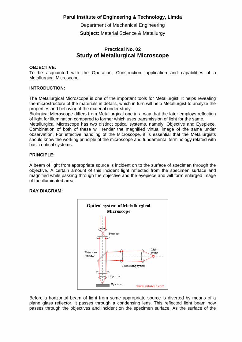
Study of Metallurgical Microscope OBJECTIVE To be acquainted with the Operation Construction application and capabilities of a Metallurgical Microscope INTRODUCTION The Metallurgical Microscope is one of the important tools for Metallurgist It helps revealing the microstructure of the materials in details which in turn will help Metallurgist to analyze the properties and behavior of the material under study Biological Microscope differs from Metallurgical one in a way that the later employs reflection of light for illumination compared to former which uses transmission of light for the same Metallurgical Microscope has two distinct optical systems namely Objective and Eyepiece Combination of both of these will render the magnified virtual image of the same under observation For effective handling of the Microscope it is essential that the Metallurgists should know the working principle of the microscope and fundamental terminology related with basic optical systems PRINCIPLE A beam of light from appropriate source is incident on to the surface of specimen through the objective A certain amount of this incident light reflected from the specimen surface and magnified while passing through the objective and the eyepiece and will form enlarged image of the illuminated area RAY DIAGRAM
Before a horizontal beam of light from some appropriate source is diverted by means of a plane glass reflector it passes through a condensing lens This reflected light beam now passes through the objectives and incident on the specimen surface As the surface of the
Parul Institute of Engineering amp Technology Limda
Department of Mechanical Engineering
Subject Material Science amp Metallurgy
specimen is polished and it is opaque in nature it reflects most of the light rays This reflected light once again passes through the objective lens system and forms an enlarged primary real image The size of primary image depends upon the relative distances at which object and image are existing from the objective The position of that image beyond the objective depends upon (1) focal length of the objective amp (2) the distance between the plane of object and the front focus point of objective The primary image formed by the objective in conjunction with the field length of the eyepiece is placed by focusing the microscope such that it is located at the focal point or within focus distance of the lens of the eyepiece If now entrance pupil of eye is made to coincide with the exit pupil of the eyepiece the eye lens in conjunction with the cornea lens of the eye will form an unreversed and erected second real image on the eye retina Due to response of human brain to excitation of the retina it will appear to be existing in space at approximately 250mm from the observer Since this third image has no existence it is known as virtual image and it will appear to be inverted and reversed When a particular combination of objective and eyepiece is used with proper tube length the total magnification is equal to the product of the magnification of the objective and the eyepiece (NB ndash The above explanation is based on the assumption that the eyepiece being used is of huygenian type If the eyepiece being used were positive type then the primary image would have been formed solely by the objectives only) Parts of Metallurgical Microscope
1) Halogen Lamp It is used as a light source This light source is especially suitable for color photomicrography
2) Intensity Variation Knob Intensity of halogen lamp can be adjust by this knob 3) Aperture Diaphragm It is placed in front of the lamp or condenser Used to control
resolving power contrast and depth of the focus 4) Filters They are required to modify the light for optimum visual examination or
photomicrography Green filters are used for observation and blue filters are used for photography
5) Plane Glass Reflector Used to divert the horizontal beam of light coming from light source onto the specimen It also transmits the reflected light from the specimen to eye-piece
6) Objective It forms the primary image in conjunction with the field lens of eyepiece It collects as much light as possible coming any point on the specimen and combines this light to form the image The Numerical aperture is a measure of the light collection capability of the objective
7) StageMounting table It is used to hold the specimen Separate knob is provided for X-Y movement of the table
8) Focusing (Fine amp Coarse) From these one can move the stage of the microscope up and down in respective type for getting clear image
9) Eyepiece It forms the second optical system They are used to enlarge the primary image formed by the objective
10) Trinocular Head This is a part of microscope in which one can attach any system like CCD camera and get image on computer
11) CCD camera CCD stands for Charge Coupled Device A CCD camera uses the same technology as the popular digital cameras used for everyday photography They are used to transfer virtual image visible in the eye piece to computer
12) Frame Grabber Card A device that lets you capture individual frames out of a video camera or off a video tape
Parul Institute of Engineering amp Technology Limda
Department of Mechanical Engineering
Subject Material Science amp Metallurgy
OBJECTIVES Objectives can be divided into four general groups namely achromates semiapochromates apochromates and monochromates which are special class of objectives to be used with ultra violet light The distinction between the first three classes is based on the design of objectives and the degree to which optical errors are corrected OPTICAL ERRORS Following two errors are observed in uncorrected objective (1) Chromatic Aberration
This error is due to light It is the failure of different wave lengths of electromagnetic radiation to come to the same focus after refraction The index of refraction of a medium such as optical glass is greater for shorter wave lengths of visible radiation passing through it When white light is passed through a simple positive lens from some source outside of its principal focus point the light will be dispersed and series of color images of the source will be focused at different points along the principal axis of the lens This type of error is known as longitudinal chromatic aberration This gives rise to the formation of colored images of unequal sizes If this type of error exists in objectives then the image will be surrounded by color halo and will lack in definition and clarity
(2) Spherical Aberration This error is due to optical system It is the loss of definition in the image arising from the surface geometry of a spherical lens or mirror When the light of definite wavelength is passed through a simple positive lens from source outside of its principal focus point a series of images of the sources will be formed along the principal axis of lens The light in passing through outermost margins of lens will be refracted to a greater degree and image formed thereby will be a point closer to the emergent side of lens than the same wavelength of light passing through the lens near the principal axis But when white light instead of monochromatic radiation is passed this error becomes more complex and when combined with other aberrational errors the attending image will appear fuzzy and indistinct
TYPES OF OBJECTIVES (1) Achromates They are relatively free from aberrational and other optical errors and of
relatively low cost They are unable to render an image that posses true color (2) Apochromates They are finest objectives corrected for high degree of perfection and
they have higher numerical aperture and higher magnification (3) Semiapochromates For aberrational errors it is compromise between achromatic and
apochromatic objectives
PROPERTIES OF OBJECTIVES (1) Magnifying power It is the ability of the objective to magnify the real object a definite
number of times without the aid of the eyepiece (2) Numerical Aperture (NA) It is light gathering ability of the objective It is because of
Numerical Aperture which for any objective is a function of the design that fine details in an object may within limits be completely and clearly resolved Resolving power of objective is proportional to NA wavelength of illumination microscope adjustments etc The amount of light received by objective is also influenced by index of refraction of objective and surface of object In case of dry objectives the medium is air
Parul Institute of Engineering amp Technology Limda
Department of Mechanical Engineering
Subject Material Science amp Metallurgy
and because of that NA is less for them If we use wet objectives then in that case the medium used is Cedar Oil hence the NA will be more
NA = n (sin μ) Where μ is half angle of light aperture n is index of refraction
n = 1 for Air 15 for Cedar Oil
(3) Resolving Power It is described as ability of an objective to produce sharply defined separate images of closely spaced details in an object It is also called fineness of detail Fineness of Detail α NA amp Fineness of Detail α 1 λ Where λ is wavelength of light used
(4) Vertical Resolution It is depth of focus or penetration It is also called ability to produce sharply focused image when the surface of object is not truly plane Vertical Resolution α 1 NA amp Vertical Resolution α 1 Initial Magnification
(5) Curvature of image field It is a condition wherein sharpness of centrally focused image declines towards the outer edge of field of view For the objectives of higher NA the effect of curvature is more but by using specific type of eyepiece image can be reduced to flat field
EYEPIECES [OCULAR] Eyepieces are used to enlarge the primary image formed by the objective and to render it visible as a virtual image or to produce the primary image as real image such as in photomicrography TYPES OF EYEPIECES (1) Negative types [hygenian] They are the most representative and simples When two
non-achromatic plano-convex lens elements are mounted in the eyepiece tube with convex sides of both elements towards the objective will form negative type of eyepiece Their focus point will lie between two lenses hence we cannot use them as ordinary magnifiers Image obtained in this case is not completely free from distortion due to lack of optical correction applied They are used with low and intermediate powered achromates
(2) Positive Types [Ramsden] When two plano-convex lens elements are mounted with convex side towards one another will form positive type of eyepiece They are consisting of two or more lens elements They combined together will behave as a positive lens Focus point in this case lies in front of field lens hence they can be used as ordinary magnifiers They have more chromatic aberration error than that of huygenian type but are better with respect to spherical errors
(3) Compensating Types They are chromatically overcorrected and can be designed either as positive type or as negative type They normally have higher magnification power They are not suitable with achromatic objectives of lower power due to adverse chromatic effects
(4) Amplifying Types They are used for photomicrography or for image projection over a short distance They are consisting of a number of lens elements which as a group works as a true negative lens system They are corrected for aberrational errors They do not form secondary image but combining together with the objectives they form final image
Parul Institute of Engineering amp Technology Limda
Department of Mechanical Engineering
Subject Material Science amp Metallurgy
ILLUMINATION SYSTEMS
Bright field illumination It is condition of lighting that renders a dark image on a bright well-lit background field Un-etched area becomes dark This happens because the reflected light is recollected by the lenses while scattered light does not get recollected The objective here first serves as condensing system to the incident light beam and then forms image This is the conventional system by which micro-examinations are carried out
Dark field illumination It is exactly the reverse condition to bright field illumination Here bright image is rendered on dark background field The objective here is used for forming image only Here only scattered light is recollected while reflected light rays are blocked This produces very strong image contrast Though this system is capable to reveal the details which are not possible by bright field system it is very difficult for out photo-microscopy
PRACTICAL CONTENTS
1) Study the operating principle of Metallurgical Microscope with the help of Ray Diagram
2) Understand various optical errors 3) Study various types of Objectives amp Eyepieces 4) Understand the illumination system and types 5) Study the important specification and capabilities of Microscope amp related computer
aided system we have QUESTIONS
1) Explain the working principle of Metallurgical Microscope with the help of Ray Diagram
2) Identify different important parts of Microscope and tabulate them mentioning their main functions
3) Explain different errors related to the objectives 4) Explain following properties of Objective briefly (Mention mathematical relations
existing between them if any) a) Magnifying Power b) Resolving Power c) Numerical Power d) Vertical Resolution
5) Explain various Objectives with their main feature 6) Explain various Eyepieces with their main feature 7) Differentiate between Dark field amp Bright field illuminations 8) List the important specifications of the Metallurgical Microscope you have studied and
explain the usefulness of computer aided system we have
REFERENCE 1) Introduction to Physical Metallurgy By Sydney H Avner 2) Principles of Metallographic Laboratory Practices By GLKehl
MARKS OBTAINED SIGNATURE OF FACULTY DATE
Parul Institute of Engineering amp Technology Limda
Department of Mechanical Engineering
Subject Material Science amp Metallurgy
Practical No 03
Specimen Preparation for Micro examination
OBJECTIVE To study procedure of specimen preparation for microscopic examination INTRODUCTION A little can be learned regarding the structural characteristics of a metal by microscopic examination unless the surface that is to be examined is first prepared according to more or less rigid and precise procedures With the use of modern metallurgical microscope and precision optical parts where the obtainable resolution may be as great as a fraction of the wavelength of the light used to illuminate the specimen it is evident that perfect specimen preparation is of the greatest importance Improper preparation is likely to remove all important inclusions erode grain boundaries of temper hardened steel specimens ultimately producing a structure superficially at least which upon micro-examination will appear entirely different from that which is truly representative and characteristic of metal Obviously an examination of such a prepared specimen will lead only to erroneous interpretations and unreliable conclusions PRACTICAL CONTENTS 1) Determine the appropriate location and orientation of the specimen to be cut 2) Mounting the specimen if required 3) If the specimen to be observed is too uneven or with burrs etc achieve plane surface by
either filling or grinding on coarse grade emery paper 4) Take emery papers from coarse to finer abrasive grid (ie 10 20 30 amp 40) The emery is
placed on any clean hard level surface The specimen is rubbed back and forth across the entire length of paper under moderately applied pressure While being ground the specimen is held so that the new finer scratches being introduced on the surface are approximately at right angles to the old scratches resulting from previous flattening operation Switch over to next finer grade and repeat the same procedure
5) Now for better surface finish go to the polishing wheel The polishing wheel mounted cloth is rotated at appropriate speed and the specimen is moved continuously from the center to the periphery of the polishing wheel with moderate pressure
6) Select suitable etchant for the specimen and carry out the etching 7) Immediately after etching wash the specimen under running water and dry it with alcohol 8) Set the microscope with suitable selection of eye piece and objective for the desired
magnification
QUESTIONS 1) What is metallography Briefly explain its importance in Metallurgy 2) What is the basic difference between low grade no emery paper and high grade no
emery paper in the intermediate polishing process 3) What is an etchant Why etching is required List at least three name of etchant used for
different material 4) List the instruments and accessories you have used for preparing the sample along with
their specification details
Parul Institute of Engineering amp Technology Limda
Department of Mechanical Engineering
Subject Material Science amp Metallurgy
REFERENCE
1) Introduction to Physical Metallurgy By Sydney H Avner 2) Principles of Metallographic Laboratory Practices By GLKehi 3) Material Science ndash By OPKhanna 4) Material Science and Engineering ndash By William D Calliater Jr
MARKS OBTAINED SIGNATURE OF FACULTY DATE
Parul Institute of Engineering amp Technology Limda
Department of Mechanical Engineering
Subject Material Science amp Metallurgy
Practical No 04
Micro-Examination of Standard Specimen
OBJECTIVE To understand procedure and relevance of Micro-Examination INTRODUCTION Microexamination is study of internal structure of a material ie microstructure which can be carried out by light microscopy or electron microscopy An observation of microstructure in a microscope will show size and shape of grains and the size shape and distribution of various phases and inclusions and segregations These structural characteristics have great effect on mechanical properties of a material The microstructure will reveal the mechanical and thermal treatment of the material and it may be possible to predict the expected behavior under a given set of conditions PRACTICAL CONTENTS
1) Select the etchant required as per the specimen 2) Carry out etching 3) Immediately after etching wash the specimen under running water and dry it
with alcohol 4) Set the microscope with suitable selection of eye piece and objective for the
desired magnification 5) Sketch the microstructure observed
QUESTIONS
1) Record the microstructure observed in microscope with the aid of schematic diagram
2) Explain the impact of microstructure on various properties of materials REFERENCE
1) Introduction to Physical Metallurgy By Sydney H Avner 2) Principles of Metallographic Laboratory Practices By GLKehl 3) Material Science ndash By OPKhanna
MARKS OBTAINED SIGNATURE OF FACULTY DATE
Parul Institute of Engineering amp Technology Limda
Department of Mechanical Engineering
Subject Material Science amp Metallurgy
Practical No 05
Demonstration of heat treatment of steel
OBJECTIVE To study of Fe ndash C system demonstrate different heat treatment processes show the effect of different quenching media (Oil water and Brine) on the hardness of steel INTRODUCTION
According to the functional requirements of the component different engineering components need different hardness for their long service life Different quenching media generate different final microstructures (like coarse pearlite fine pearlite bainite martensite etc) and thus give different hardness values So the type of quenching media and the cooling rate both decide the final microstructure To derive the suitable hardness material technologists must know the effect of the quenching
Parul Institute of Engineering amp Technology Limda
Department of Mechanical Engineering
Subject Material Science amp Metallurgy
medium and cooling rate on the hardness of steel Knowledge of generating different hardness is of great help in industries for the manufacture of components like gears cams shafts axles pins etc to increase their service life THEORY Quenching which means drastic(rapid) cooling always gives high hardness in ferrous systems (metal involving iron) because of mechanism of allotropic transformation suppression Mechanism of heat removal during quenching is grouped into three stages 1) Vapour Blanket Stage Here the quenching medium (Oil Water or Brine)
vaporizes at the metal surface due to the high temperature and a thin film of vapour called vapour blanket surrounds the hot metal Presence of vapour retards the heat transfer process and hence the rate of cooling is relatively low
2) Vapour Transport Cooling Rate Here metal has cooled a temperature where
vapour blanket is no longer stable Because of absence of vapour between metal and liquid heat transfer rate increases and cooling rate is maximum
3) Liquid Cooling Stage Here the metal reaches the temperature of boiling point of
quenching medium Heat given by the hot metal is utilized in boiling the liquid In this stage cooling rate is lowest
To avoid cracks distortion and warpage quenching medium should show high initial cooling rate to avoid transformation in the nose region of the TTT curve followed by slow cooling rate through out the low temperature range Rise in temperature of quenching medium due to immersion of the component should be controlled by selecting the proper volume of quenching medium along with necessary cooling arrangement so that heat transfer rate gets maintained the level desired PRACTICAL CONTENTS 1) Measure the initial hardness of the given specimen on Rockwell Hardness Tester 2) Load these specimens in the furnace and heat them to the hardening temperature
for 20 to 30 minute 3) Quench these specimens in oil water and brine respectively 4) Measure the hardness of each of them after cooling
QUESTIONS 1) Draw the Fe ndash Fe3C diagram with all major transformations 2) What is soaking time State its importance 3) Enlist various heat treatment processes 4) What is the necessity of studying the effect of quenching media
Parul Institute of Engineering amp Technology Limda
Department of Mechanical Engineering
Subject Material Science amp Metallurgy
5) What should be the nature of quenching media to avoid cracks distortion or warpage of component being hardened
REFERENCE 1) Introduction to physical metallurgy Sydney H Avner 2) Physical Metallurgy principles Reed Hill 3) Materials science and engineering William D Callister Jr
MARKS OBTAINED SIGNATURE OF FACULTY DATE
Parul Institute of Engineering amp Technology Limda
Department of Mechanical Engineering
Subject Material Science amp Metallurgy
Practical No 06
Study of powder metallurgy OBJECTIVE To understand various processes of powder metallurgy INTRODUCTION
Powder metallurgy is the process of blending fine powdered materials pressing them into a desired shape or form (compacting) and then heating the compressed material in a controlled atmosphere to bond the material (sintering) The powder metallurgy process generally consists of four basic steps (1) powder manufacture (2) powder blending(3) compacting (4) sintering Compacting is generally performed at room temperature and the elevated-temperature process of sintering is usually conducted at atmospheric pressure Optional secondary processing often follows to obtain special properties or enhanced precision[1]
Two main techniques used to form and consolidate the powder are sintering and metal injection molding Recent developments have made it possible to use rapid manufacturing techniques which use the metal powder for the products Because with this technique the powder is melted and not sintered better mechanical strength can be accomplished
PRACTICAL CONTENTS QUESTIONS REFERENCE
1) Introduction to Poeder Metallurgy By A K Sinha 2) Principles of Metallographic Laboratory Practices By GLKehl 3) Material Science ndash By OPKhanna
MARKS OBTAINED SIGNATURE OF FACULTY DATE
Parul Institute of Engineering amp Technology Limda
Department of Mechanical Engineering
Subject Material Science amp Metallurgy
Practical No 07
Ultrasonic Test
OBJECTIVE To understand principle procedure and capabilities of ultrasonic test INTRODUCTION The basic principle of the method is detecting the change in attenuation of sound energy (ultrasonic) ndash the change being caused by a flaw or the material In this test ultrasonic sound waves (above the audible range) capable of penetrating and medium of appreciable thickness at speeds of several thousand metersec are used The frequency may range from 1 to 15 MHz There will be changes in probing medium when there is a flaw which will be detected and indicated by the equipment ndash the ultrasonic flaw detector The pulse-echo technique is widely preferred This employs a single probe (transducer) as transmitter and receiver of ultrasonic waves The ultrasonic waves with high frequency are generated by piezoelectric effect When these high frequency waves enter the material being tested part of it is reflected and converted back to an electrical impulse This electrical impulse is amplified and rendered visible as an indicator or pip on the screen of the oscilloscope When the sound wave reaches the other side of the other side of the material it is reflected back and shows as another pip on the screen further to the right of the first pip (pulse) If there is a flaw between the front and back surfaces of the material (ie the thickness) it will show as a third pip (pulse) on the screen between the two indications or pulses Since the indications on the oscilloscope screen measure the elapsed time between reflection of the pulse from the front and back surfaces the distance between indications is a measure of thickness of the material The location of a defect can therefore be accurately determined from the location on the screen Angle probes may be used to detect flaws which are not oriented perpendicular to the direction of propagation of sound waves PRACTICAL CONTENTS 1) With the help of the manual of the equipment get acquainted with the operating details of
ultrasonic flaw detector 2) Calibrate the instrument using IIW-V1 Block 3) Scan the given samples and report the indications in following manner
Sr No CRT Reading Length of defect from probing surface (mm)
4) Sketch the samples you have scanned illustrating the flaws in it
Parul Institute of Engineering amp Technology Limda
Department of Mechanical Engineering
Subject Material Science amp Metallurgy
QUESTIONS 1) Briefly explain the principle of Ultrasonic Testing State various methods of conducting UT
and sketch the operating principle of the method you have used in lab 2) Evaluate UT with other with respect to other NDT methods you know 3) Illustrate internal construction of following probes and mention the selection criteria for
each of them a) Normal Probe b) Dual Crystal Probe c) Angle Probe
4) Explain briefly following terminology in context of UT a) Attenuation b) Dead Zone c) Near Zone d) Couplants e) Acoustic impedance f) Sensitivity
REFERENCE 1) Introduction to physical metallurgy Sydney H Avner 2) Instrument manual available in Lab 3) Material Science And Engineering William D Callister 4) Practical Non-Destructive Testing Raj Baldev Jayakumar T amp Thavasimuthu M
MARKS OBTAINED SIGNATURE OF FACULTY DATE
Parul Institute of Engineering amp Technology Limda
Department of Mechanical Engineering
Subject Material Science amp Metallurgy
Practical No 08
Magnetic Particle Test
OBJECTIVE To understand principle procedure amp capabilities of Magnetic Particle Test INTRODUCTION The magnetic particle test is one of the most powerful surface andor subsurface crack detection methods for Ferromagnetic Materials The principle of the operation is that when a component under test is magnetized discontinuities which lie in a direction generally transverse to the direction of magnetic field will cause a leakage field to be formed If leakage field is strong enough its presence and therefore the discontinuity is detected by use of finely divided ferromagnetic particles applied over the surface Some of the ferromagnetic particles are influence by leakage field and form an outline of the discontinuity called as an indication The indication may give about size shape and location of the flaw PRACTICAL CONTENTS 1) Determine the setting up procedure parameters 2) Clean the specimen thoroughly Degreasing may be carried out by spirit or
trichloroethylene bath 3) Setup the equipment for the nature of the defect to be detected (cracks surface
subsurface porosity etc) Based on it select the electrical current source 4) Apply magnetic particles 5) Perform the test in different orientations of magnetic field application and record
the nature and extent of indication with and without fluorescent powder 6) Demagnetize the work piece and check for results QUESTIONS 1) Briefly explain the principle and procedure of MPT with neat sketches 2) Comment on applications advantages and limitations of MPT
REFERENCE 1) Introduction to physical metallurgy Sydney H Avner 2) Instrument manual available in Lab
MARKS OBTAINED SIGNATURE OF FACULTY DATE
Parul Institute of Engineering amp Technology Limda
Department of Mechanical Engineering
Subject Material Science amp Metallurgy
Practical No 09
Dye Penetrant Test OBJECTIVE To understand principle procedure amp capabilities of Liquid Dye Penetrant Test INTRODUCTION Dye penetrant test is essentially useful in detecting minute discontinuities such as cracks shrinkages and porosity that are open to the surface Parts to be tested are treated with a penetrant Penetrant is usually light oil-like liquids which is applied by dipping spraying or brushing or in some other convenient manner The liquid penetrant is drawn into cracks and other discontinuities by strong capillary action After the penetrant ahs had time to seep in the portion remaining on the surface is removed by wiping or washing This leaves the penetrant in all surface-connected discontinuities The pest part is now treated with a dry powder or a suspension of powder in a liquid This powder or developer acts like a sponge drawing the penetrant from the defect and enlarging the size of the area of penetrant indication PRACTICAL CONTENTS
1) Prepare the surface to be investigated and make it free from dirt and grease 2) Apply cleaner allow some time so that surface gets dried 3) Spray dye penetrant on the surface and allow some time (usually 3 to 5 min varies
from 2 min to few days) 4) Wipe out excess penetrant (This may be carried out by a light spray of cleaner and
wiping it out) 5) Apply developer and observer indications 6) If needed the developer once again 7) Observe the defect
QUESTIONS 1) What types of properties of the dye are required to perform the LPT accurately 2) Why the developer is used in LPT 3) List the limitation amp capabilities of LPT 4) Mention the IS No for DPT 5) Draw the neat sketch of sample amp indications
REFERENCE 1) Introduction to physical metallurgy Sydney H Avner 2) Practical Non Destructive Testing Raj Baldev Jayakumar T Thavasimuthu M 3) httpwwwndt-edorgEducationResourcesCommunityCollegeRadiographycc_
rad_indexhtm
MARKS OBTAINED SIGNATURE OF FACULTY DATE
Parul Institute of Engineering amp Technology Limda
Department of Mechanical Engineering
Subject Material Science amp Metallurgy
Practical No 10
Study of Eddy current test amp Radiography test
OBJECTIVE To understand principle procedure amp capabilities of Eddy current test amp Radiography test INTRODUCTION
Eddy-current testing uses electromagnetic induction to detect flaws in conductive materials There are several limitations among them only conductive materials can be tested the surface of the material must be accessible the finish of the material may cause bad readings the depth of penetration into the material is limited by the materials conductivity and flaws that lie parallel to the probe may be undetectable
Eddy current inspection is one of several NDT methods that use the principal of ldquoelectromagnetismrdquo as the basis for conducting examinations Several other methods such as Remote Field Testing (RFT) Flux Leakage and Barkhausen Noise also use this principle
Eddy currents are created through a process called electromagnetic induction When alternating current is applied to the conductor such as copper wire a magnetic field develops in and around the conductor This magnetic field expands as the alternating current rises to maximum and collapses as the current is reduced to zero If another electrical conductor is brought into the close proximity to this changing magnetic field current will be induced in this second conductor Eddy currents are induced electrical currents that flow in a circular path They get their name from ldquoeddiesrdquo that are formed when a liquid or gas flows in a circular path around obstacles when conditions are right
In a standard eddy current testing a circular coil carrying current is placed in proximity to the test specimen (which must be electrically conductive)The alternating current in the coil generates changing magnetic field which interacts with test specimen and generates eddy currentVariations in the phase and magnitude of these eddy currents can be monitored using a second receiver coil or by measuring changes to the current flowing in the primary excitation coil Variations in the electrical conductivity or magnetic permeability of the test object or the presence of any flaws will cause a change in eddy current and a corresponding change in the phase and amplitude of the measured current This is the basis of standard (flat coil) eddy current inspection the most widely used eddy current technique
However eddy-current testing can detect very small cracks in or near the surface of the material the surfaces need minimal preparation and physically complex geometries can be investigated It is also useful for making electrical conductivity and coating thickness measurements
Radiation Safety
Ionizing radiation is an extremely important NDT tool but it can pose a hazard to human health For this reason special precautions must be observed when using and working around ionizing radiation The possession of radioactive materials and use of radiation producing devices in the United States is governed by strict regulatory controls The primary regulatory authority for most types and uses of radioactive materials is the federal Nuclear Regulatory Commission (NRC) However more than half of the states in the US have entered into
Parul Institute of Engineering amp Technology Limda
Department of Mechanical Engineering
Subject Material Science amp Metallurgy
agreement with the NRC to assume regulatory control of radioactive material use within their borders As part of the agreement process the states must adopt and enforce regulations comparable to those found in Title 10 of the Code of Federal Regulations Regulations for control of radioactive material used in Iowa are found in Chapter 136C of the Iowa Code
For most situations the types and maximum quantities of radioactive materials possessed the manner in which they may be used and the individuals authorized to use radioactive materials are stipulated in the form of a specific license from the appropriate regulatory authority In Iowa this authority is the Iowa Department of Public Health However for certain institutions which routinely use large quantities of numerous types of radioactive materials the exact quantities of materials and details of use may not be specified in the license Instead the license grants the institution the authority and responsibility for setting the specific requirements for radioactive material use within its facilities These licensees are termed broadscope and require a Radiation Safety Committee and usually a full-time Radiation Safety Officer
PRACTICAL CONTENTS
1) Prepare the surface to be investigated and make it free from dirt and grease 2) Observe the defect
QUESTIONS 1) Explain principle of Eddy current test 2) Explain principle of Radiography test 3) Enlist merits amp demerits of Eddy current test amp Radiography test 4) What precaution one has to take before doing radiography test why
REFERENCE 1) Introduction to physical metallurgy Sydney H Avner 2) Practical Non Destructive Testing Raj Baldev Jayakumar T Thavasimuthu M 3) httpwwwndt-edorgEducationResourcesCommunityCollegeRadiographycc_
rad_indexhtm
MARKS OBTAINED SIGNATURE OF FACULTY DATE
Parul Institute of Engineering amp Technology Limda
Department of Mechanical Engineering
Subject Material Science amp Metallurgy
Practical No 11
Jominy Hardenability Test OBJECTIVE To understand the concept of hardenability and its relevance to heat treatment procedure to be adopted in practice INTRODUCTION Hardenability is the property that determines the depth and distribution of hardness induced by quenching in a ferrous alloy The Jominy test together with the appropriate data is ideally suited for predicting the hardness at a particular location within a section of any given size regardless of the steel from which the section is made It establishes a correlation between the cooling rate and corresponding distance from the quenched end for each of the test bars This relationship is the fundamental one and remains substantially unaltered so long as the Jominy procedure is strictly adhered to It is possible through this correlation to predict hardness within any given shaped object once the cooling rate is known at the location of interest Such cooling rates within the objects may be determined experimentally or may be obtained by reference to appropriate published data if the size shape and heat treatment of the object correspond to the condition under which data were obtained PRACTICAL CONTENTS 1) Understand the theory and relevance of hardenability 2) Heat the specimen to the austenitizing temperature and soak it at this temperature
for 30 minutes 3) After soaking a test specimen is removed rapidly and placed on a quenching
fixture 4) The water tap shall be opened as soon as the test piece is fixed in position and the
time of spraying shall be at least 10 minutes After this time the cooling of the test specimen is removed rapidly and placed on a quenching fixture
5) Two flats for measuring the hardness shall be ground on the surface 1800 apart and parallel to the axis of the test piece along its entire length They should be 04 to 05 mm deep shall be ground with an abundant supply of coolant so as to prevent any heating likely to modify the microstructure of the quenched test piece
6) Rockwell hardness measurements are made at an interval of 15 mm along the longitudinal center line of the flat surface
7) Record the observations as under
Specimen Material Hardness before test Temperature amp Socking Time
Sr No Distance from the quenched end (mm) Hardness (HRC)
Parul Institute of Engineering amp Technology Limda
Department of Mechanical Engineering
Subject Material Science amp Metallurgy
8) Plot the graph of Distance vs Hardness
QUESTIONS 1) Draw the neat diagram of standard specimen and practical set up 2) What is hardenability What are the factors on which hardenability depends 3) What kind of transformation is desirable to have a greater hardenability 4) Differentiate between hardness and hardenability 5) What is the grain structure of martensite 6) How is hardenability curve useful 7) Why it is necessary to cool the test specimen of Jominy hardenability test while
grinding two flat surfaces for measurement purpose REFERENCE 1) Introduction to physical metallurgy Sydney H Avner 2) Physical Metallurgy Principles Reed Hill 3) Material Science And Engineering William D Callister
MARKS OBTAINED SIGNATURE OF FACULTY DATE
Parul Institute of Engineering amp Technology Limda
Department of Mechanical Engineering
Subject Material Science amp Metallurgy
Practical No 02
Study of Metallurgical Microscope OBJECTIVE To be acquainted with the Operation Construction application and capabilities of a Metallurgical Microscope INTRODUCTION The Metallurgical Microscope is one of the important tools for Metallurgist It helps revealing the microstructure of the materials in details which in turn will help Metallurgist to analyze the properties and behavior of the material under study Biological Microscope differs from Metallurgical one in a way that the later employs reflection of light for illumination compared to former which uses transmission of light for the same Metallurgical Microscope has two distinct optical systems namely Objective and Eyepiece Combination of both of these will render the magnified virtual image of the same under observation For effective handling of the Microscope it is essential that the Metallurgists should know the working principle of the microscope and fundamental terminology related with basic optical systems PRINCIPLE A beam of light from appropriate source is incident on to the surface of specimen through the objective A certain amount of this incident light reflected from the specimen surface and magnified while passing through the objective and the eyepiece and will form enlarged image of the illuminated area RAY DIAGRAM
Before a horizontal beam of light from some appropriate source is diverted by means of a plane glass reflector it passes through a condensing lens This reflected light beam now passes through the objectives and incident on the specimen surface As the surface of the
Parul Institute of Engineering amp Technology Limda
Department of Mechanical Engineering
Subject Material Science amp Metallurgy
specimen is polished and it is opaque in nature it reflects most of the light rays This reflected light once again passes through the objective lens system and forms an enlarged primary real image The size of primary image depends upon the relative distances at which object and image are existing from the objective The position of that image beyond the objective depends upon (1) focal length of the objective amp (2) the distance between the plane of object and the front focus point of objective The primary image formed by the objective in conjunction with the field length of the eyepiece is placed by focusing the microscope such that it is located at the focal point or within focus distance of the lens of the eyepiece If now entrance pupil of eye is made to coincide with the exit pupil of the eyepiece the eye lens in conjunction with the cornea lens of the eye will form an unreversed and erected second real image on the eye retina Due to response of human brain to excitation of the retina it will appear to be existing in space at approximately 250mm from the observer Since this third image has no existence it is known as virtual image and it will appear to be inverted and reversed When a particular combination of objective and eyepiece is used with proper tube length the total magnification is equal to the product of the magnification of the objective and the eyepiece (NB ndash The above explanation is based on the assumption that the eyepiece being used is of huygenian type If the eyepiece being used were positive type then the primary image would have been formed solely by the objectives only) Parts of Metallurgical Microscope
1) Halogen Lamp It is used as a light source This light source is especially suitable for color photomicrography
2) Intensity Variation Knob Intensity of halogen lamp can be adjust by this knob 3) Aperture Diaphragm It is placed in front of the lamp or condenser Used to control
resolving power contrast and depth of the focus 4) Filters They are required to modify the light for optimum visual examination or
photomicrography Green filters are used for observation and blue filters are used for photography
5) Plane Glass Reflector Used to divert the horizontal beam of light coming from light source onto the specimen It also transmits the reflected light from the specimen to eye-piece
6) Objective It forms the primary image in conjunction with the field lens of eyepiece It collects as much light as possible coming any point on the specimen and combines this light to form the image The Numerical aperture is a measure of the light collection capability of the objective
7) StageMounting table It is used to hold the specimen Separate knob is provided for X-Y movement of the table
8) Focusing (Fine amp Coarse) From these one can move the stage of the microscope up and down in respective type for getting clear image
9) Eyepiece It forms the second optical system They are used to enlarge the primary image formed by the objective
10) Trinocular Head This is a part of microscope in which one can attach any system like CCD camera and get image on computer
11) CCD camera CCD stands for Charge Coupled Device A CCD camera uses the same technology as the popular digital cameras used for everyday photography They are used to transfer virtual image visible in the eye piece to computer
12) Frame Grabber Card A device that lets you capture individual frames out of a video camera or off a video tape
Parul Institute of Engineering amp Technology Limda
Department of Mechanical Engineering
Subject Material Science amp Metallurgy
OBJECTIVES Objectives can be divided into four general groups namely achromates semiapochromates apochromates and monochromates which are special class of objectives to be used with ultra violet light The distinction between the first three classes is based on the design of objectives and the degree to which optical errors are corrected OPTICAL ERRORS Following two errors are observed in uncorrected objective (1) Chromatic Aberration
This error is due to light It is the failure of different wave lengths of electromagnetic radiation to come to the same focus after refraction The index of refraction of a medium such as optical glass is greater for shorter wave lengths of visible radiation passing through it When white light is passed through a simple positive lens from some source outside of its principal focus point the light will be dispersed and series of color images of the source will be focused at different points along the principal axis of the lens This type of error is known as longitudinal chromatic aberration This gives rise to the formation of colored images of unequal sizes If this type of error exists in objectives then the image will be surrounded by color halo and will lack in definition and clarity
(2) Spherical Aberration This error is due to optical system It is the loss of definition in the image arising from the surface geometry of a spherical lens or mirror When the light of definite wavelength is passed through a simple positive lens from source outside of its principal focus point a series of images of the sources will be formed along the principal axis of lens The light in passing through outermost margins of lens will be refracted to a greater degree and image formed thereby will be a point closer to the emergent side of lens than the same wavelength of light passing through the lens near the principal axis But when white light instead of monochromatic radiation is passed this error becomes more complex and when combined with other aberrational errors the attending image will appear fuzzy and indistinct
TYPES OF OBJECTIVES (1) Achromates They are relatively free from aberrational and other optical errors and of
relatively low cost They are unable to render an image that posses true color (2) Apochromates They are finest objectives corrected for high degree of perfection and
they have higher numerical aperture and higher magnification (3) Semiapochromates For aberrational errors it is compromise between achromatic and
apochromatic objectives
PROPERTIES OF OBJECTIVES (1) Magnifying power It is the ability of the objective to magnify the real object a definite
number of times without the aid of the eyepiece (2) Numerical Aperture (NA) It is light gathering ability of the objective It is because of
Numerical Aperture which for any objective is a function of the design that fine details in an object may within limits be completely and clearly resolved Resolving power of objective is proportional to NA wavelength of illumination microscope adjustments etc The amount of light received by objective is also influenced by index of refraction of objective and surface of object In case of dry objectives the medium is air
Parul Institute of Engineering amp Technology Limda
Department of Mechanical Engineering
Subject Material Science amp Metallurgy
and because of that NA is less for them If we use wet objectives then in that case the medium used is Cedar Oil hence the NA will be more
NA = n (sin μ) Where μ is half angle of light aperture n is index of refraction
n = 1 for Air 15 for Cedar Oil
(3) Resolving Power It is described as ability of an objective to produce sharply defined separate images of closely spaced details in an object It is also called fineness of detail Fineness of Detail α NA amp Fineness of Detail α 1 λ Where λ is wavelength of light used
(4) Vertical Resolution It is depth of focus or penetration It is also called ability to produce sharply focused image when the surface of object is not truly plane Vertical Resolution α 1 NA amp Vertical Resolution α 1 Initial Magnification
(5) Curvature of image field It is a condition wherein sharpness of centrally focused image declines towards the outer edge of field of view For the objectives of higher NA the effect of curvature is more but by using specific type of eyepiece image can be reduced to flat field
EYEPIECES [OCULAR] Eyepieces are used to enlarge the primary image formed by the objective and to render it visible as a virtual image or to produce the primary image as real image such as in photomicrography TYPES OF EYEPIECES (1) Negative types [hygenian] They are the most representative and simples When two
non-achromatic plano-convex lens elements are mounted in the eyepiece tube with convex sides of both elements towards the objective will form negative type of eyepiece Their focus point will lie between two lenses hence we cannot use them as ordinary magnifiers Image obtained in this case is not completely free from distortion due to lack of optical correction applied They are used with low and intermediate powered achromates
(2) Positive Types [Ramsden] When two plano-convex lens elements are mounted with convex side towards one another will form positive type of eyepiece They are consisting of two or more lens elements They combined together will behave as a positive lens Focus point in this case lies in front of field lens hence they can be used as ordinary magnifiers They have more chromatic aberration error than that of huygenian type but are better with respect to spherical errors
(3) Compensating Types They are chromatically overcorrected and can be designed either as positive type or as negative type They normally have higher magnification power They are not suitable with achromatic objectives of lower power due to adverse chromatic effects
(4) Amplifying Types They are used for photomicrography or for image projection over a short distance They are consisting of a number of lens elements which as a group works as a true negative lens system They are corrected for aberrational errors They do not form secondary image but combining together with the objectives they form final image
Parul Institute of Engineering amp Technology Limda
Department of Mechanical Engineering
Subject Material Science amp Metallurgy
ILLUMINATION SYSTEMS
Bright field illumination It is condition of lighting that renders a dark image on a bright well-lit background field Un-etched area becomes dark This happens because the reflected light is recollected by the lenses while scattered light does not get recollected The objective here first serves as condensing system to the incident light beam and then forms image This is the conventional system by which micro-examinations are carried out
Dark field illumination It is exactly the reverse condition to bright field illumination Here bright image is rendered on dark background field The objective here is used for forming image only Here only scattered light is recollected while reflected light rays are blocked This produces very strong image contrast Though this system is capable to reveal the details which are not possible by bright field system it is very difficult for out photo-microscopy
PRACTICAL CONTENTS
1) Study the operating principle of Metallurgical Microscope with the help of Ray Diagram
2) Understand various optical errors 3) Study various types of Objectives amp Eyepieces 4) Understand the illumination system and types 5) Study the important specification and capabilities of Microscope amp related computer
aided system we have QUESTIONS
1) Explain the working principle of Metallurgical Microscope with the help of Ray Diagram
2) Identify different important parts of Microscope and tabulate them mentioning their main functions
3) Explain different errors related to the objectives 4) Explain following properties of Objective briefly (Mention mathematical relations
existing between them if any) a) Magnifying Power b) Resolving Power c) Numerical Power d) Vertical Resolution
5) Explain various Objectives with their main feature 6) Explain various Eyepieces with their main feature 7) Differentiate between Dark field amp Bright field illuminations 8) List the important specifications of the Metallurgical Microscope you have studied and
explain the usefulness of computer aided system we have
REFERENCE 1) Introduction to Physical Metallurgy By Sydney H Avner 2) Principles of Metallographic Laboratory Practices By GLKehl
MARKS OBTAINED SIGNATURE OF FACULTY DATE
Parul Institute of Engineering amp Technology Limda
Department of Mechanical Engineering
Subject Material Science amp Metallurgy
Practical No 03
Specimen Preparation for Micro examination
OBJECTIVE To study procedure of specimen preparation for microscopic examination INTRODUCTION A little can be learned regarding the structural characteristics of a metal by microscopic examination unless the surface that is to be examined is first prepared according to more or less rigid and precise procedures With the use of modern metallurgical microscope and precision optical parts where the obtainable resolution may be as great as a fraction of the wavelength of the light used to illuminate the specimen it is evident that perfect specimen preparation is of the greatest importance Improper preparation is likely to remove all important inclusions erode grain boundaries of temper hardened steel specimens ultimately producing a structure superficially at least which upon micro-examination will appear entirely different from that which is truly representative and characteristic of metal Obviously an examination of such a prepared specimen will lead only to erroneous interpretations and unreliable conclusions PRACTICAL CONTENTS 1) Determine the appropriate location and orientation of the specimen to be cut 2) Mounting the specimen if required 3) If the specimen to be observed is too uneven or with burrs etc achieve plane surface by
either filling or grinding on coarse grade emery paper 4) Take emery papers from coarse to finer abrasive grid (ie 10 20 30 amp 40) The emery is
placed on any clean hard level surface The specimen is rubbed back and forth across the entire length of paper under moderately applied pressure While being ground the specimen is held so that the new finer scratches being introduced on the surface are approximately at right angles to the old scratches resulting from previous flattening operation Switch over to next finer grade and repeat the same procedure
5) Now for better surface finish go to the polishing wheel The polishing wheel mounted cloth is rotated at appropriate speed and the specimen is moved continuously from the center to the periphery of the polishing wheel with moderate pressure
6) Select suitable etchant for the specimen and carry out the etching 7) Immediately after etching wash the specimen under running water and dry it with alcohol 8) Set the microscope with suitable selection of eye piece and objective for the desired
magnification
QUESTIONS 1) What is metallography Briefly explain its importance in Metallurgy 2) What is the basic difference between low grade no emery paper and high grade no
emery paper in the intermediate polishing process 3) What is an etchant Why etching is required List at least three name of etchant used for
different material 4) List the instruments and accessories you have used for preparing the sample along with
their specification details
Parul Institute of Engineering amp Technology Limda
Department of Mechanical Engineering
Subject Material Science amp Metallurgy
REFERENCE
1) Introduction to Physical Metallurgy By Sydney H Avner 2) Principles of Metallographic Laboratory Practices By GLKehi 3) Material Science ndash By OPKhanna 4) Material Science and Engineering ndash By William D Calliater Jr
MARKS OBTAINED SIGNATURE OF FACULTY DATE
Parul Institute of Engineering amp Technology Limda
Department of Mechanical Engineering
Subject Material Science amp Metallurgy
Practical No 04
Micro-Examination of Standard Specimen
OBJECTIVE To understand procedure and relevance of Micro-Examination INTRODUCTION Microexamination is study of internal structure of a material ie microstructure which can be carried out by light microscopy or electron microscopy An observation of microstructure in a microscope will show size and shape of grains and the size shape and distribution of various phases and inclusions and segregations These structural characteristics have great effect on mechanical properties of a material The microstructure will reveal the mechanical and thermal treatment of the material and it may be possible to predict the expected behavior under a given set of conditions PRACTICAL CONTENTS
1) Select the etchant required as per the specimen 2) Carry out etching 3) Immediately after etching wash the specimen under running water and dry it
with alcohol 4) Set the microscope with suitable selection of eye piece and objective for the
desired magnification 5) Sketch the microstructure observed
QUESTIONS
1) Record the microstructure observed in microscope with the aid of schematic diagram
2) Explain the impact of microstructure on various properties of materials REFERENCE
1) Introduction to Physical Metallurgy By Sydney H Avner 2) Principles of Metallographic Laboratory Practices By GLKehl 3) Material Science ndash By OPKhanna
MARKS OBTAINED SIGNATURE OF FACULTY DATE
Parul Institute of Engineering amp Technology Limda
Department of Mechanical Engineering
Subject Material Science amp Metallurgy
Practical No 05
Demonstration of heat treatment of steel
OBJECTIVE To study of Fe ndash C system demonstrate different heat treatment processes show the effect of different quenching media (Oil water and Brine) on the hardness of steel INTRODUCTION
According to the functional requirements of the component different engineering components need different hardness for their long service life Different quenching media generate different final microstructures (like coarse pearlite fine pearlite bainite martensite etc) and thus give different hardness values So the type of quenching media and the cooling rate both decide the final microstructure To derive the suitable hardness material technologists must know the effect of the quenching
Parul Institute of Engineering amp Technology Limda
Department of Mechanical Engineering
Subject Material Science amp Metallurgy
medium and cooling rate on the hardness of steel Knowledge of generating different hardness is of great help in industries for the manufacture of components like gears cams shafts axles pins etc to increase their service life THEORY Quenching which means drastic(rapid) cooling always gives high hardness in ferrous systems (metal involving iron) because of mechanism of allotropic transformation suppression Mechanism of heat removal during quenching is grouped into three stages 1) Vapour Blanket Stage Here the quenching medium (Oil Water or Brine)
vaporizes at the metal surface due to the high temperature and a thin film of vapour called vapour blanket surrounds the hot metal Presence of vapour retards the heat transfer process and hence the rate of cooling is relatively low
2) Vapour Transport Cooling Rate Here metal has cooled a temperature where
vapour blanket is no longer stable Because of absence of vapour between metal and liquid heat transfer rate increases and cooling rate is maximum
3) Liquid Cooling Stage Here the metal reaches the temperature of boiling point of
quenching medium Heat given by the hot metal is utilized in boiling the liquid In this stage cooling rate is lowest
To avoid cracks distortion and warpage quenching medium should show high initial cooling rate to avoid transformation in the nose region of the TTT curve followed by slow cooling rate through out the low temperature range Rise in temperature of quenching medium due to immersion of the component should be controlled by selecting the proper volume of quenching medium along with necessary cooling arrangement so that heat transfer rate gets maintained the level desired PRACTICAL CONTENTS 1) Measure the initial hardness of the given specimen on Rockwell Hardness Tester 2) Load these specimens in the furnace and heat them to the hardening temperature
for 20 to 30 minute 3) Quench these specimens in oil water and brine respectively 4) Measure the hardness of each of them after cooling
QUESTIONS 1) Draw the Fe ndash Fe3C diagram with all major transformations 2) What is soaking time State its importance 3) Enlist various heat treatment processes 4) What is the necessity of studying the effect of quenching media
Parul Institute of Engineering amp Technology Limda
Department of Mechanical Engineering
Subject Material Science amp Metallurgy
5) What should be the nature of quenching media to avoid cracks distortion or warpage of component being hardened
REFERENCE 1) Introduction to physical metallurgy Sydney H Avner 2) Physical Metallurgy principles Reed Hill 3) Materials science and engineering William D Callister Jr
MARKS OBTAINED SIGNATURE OF FACULTY DATE
Parul Institute of Engineering amp Technology Limda
Department of Mechanical Engineering
Subject Material Science amp Metallurgy
Practical No 06
Study of powder metallurgy OBJECTIVE To understand various processes of powder metallurgy INTRODUCTION
Powder metallurgy is the process of blending fine powdered materials pressing them into a desired shape or form (compacting) and then heating the compressed material in a controlled atmosphere to bond the material (sintering) The powder metallurgy process generally consists of four basic steps (1) powder manufacture (2) powder blending(3) compacting (4) sintering Compacting is generally performed at room temperature and the elevated-temperature process of sintering is usually conducted at atmospheric pressure Optional secondary processing often follows to obtain special properties or enhanced precision[1]
Two main techniques used to form and consolidate the powder are sintering and metal injection molding Recent developments have made it possible to use rapid manufacturing techniques which use the metal powder for the products Because with this technique the powder is melted and not sintered better mechanical strength can be accomplished
PRACTICAL CONTENTS QUESTIONS REFERENCE
1) Introduction to Poeder Metallurgy By A K Sinha 2) Principles of Metallographic Laboratory Practices By GLKehl 3) Material Science ndash By OPKhanna
MARKS OBTAINED SIGNATURE OF FACULTY DATE
Parul Institute of Engineering amp Technology Limda
Department of Mechanical Engineering
Subject Material Science amp Metallurgy
Practical No 07
Ultrasonic Test
OBJECTIVE To understand principle procedure and capabilities of ultrasonic test INTRODUCTION The basic principle of the method is detecting the change in attenuation of sound energy (ultrasonic) ndash the change being caused by a flaw or the material In this test ultrasonic sound waves (above the audible range) capable of penetrating and medium of appreciable thickness at speeds of several thousand metersec are used The frequency may range from 1 to 15 MHz There will be changes in probing medium when there is a flaw which will be detected and indicated by the equipment ndash the ultrasonic flaw detector The pulse-echo technique is widely preferred This employs a single probe (transducer) as transmitter and receiver of ultrasonic waves The ultrasonic waves with high frequency are generated by piezoelectric effect When these high frequency waves enter the material being tested part of it is reflected and converted back to an electrical impulse This electrical impulse is amplified and rendered visible as an indicator or pip on the screen of the oscilloscope When the sound wave reaches the other side of the other side of the material it is reflected back and shows as another pip on the screen further to the right of the first pip (pulse) If there is a flaw between the front and back surfaces of the material (ie the thickness) it will show as a third pip (pulse) on the screen between the two indications or pulses Since the indications on the oscilloscope screen measure the elapsed time between reflection of the pulse from the front and back surfaces the distance between indications is a measure of thickness of the material The location of a defect can therefore be accurately determined from the location on the screen Angle probes may be used to detect flaws which are not oriented perpendicular to the direction of propagation of sound waves PRACTICAL CONTENTS 1) With the help of the manual of the equipment get acquainted with the operating details of
ultrasonic flaw detector 2) Calibrate the instrument using IIW-V1 Block 3) Scan the given samples and report the indications in following manner
Sr No CRT Reading Length of defect from probing surface (mm)
4) Sketch the samples you have scanned illustrating the flaws in it
Parul Institute of Engineering amp Technology Limda
Department of Mechanical Engineering
Subject Material Science amp Metallurgy
QUESTIONS 1) Briefly explain the principle of Ultrasonic Testing State various methods of conducting UT
and sketch the operating principle of the method you have used in lab 2) Evaluate UT with other with respect to other NDT methods you know 3) Illustrate internal construction of following probes and mention the selection criteria for
each of them a) Normal Probe b) Dual Crystal Probe c) Angle Probe
4) Explain briefly following terminology in context of UT a) Attenuation b) Dead Zone c) Near Zone d) Couplants e) Acoustic impedance f) Sensitivity
REFERENCE 1) Introduction to physical metallurgy Sydney H Avner 2) Instrument manual available in Lab 3) Material Science And Engineering William D Callister 4) Practical Non-Destructive Testing Raj Baldev Jayakumar T amp Thavasimuthu M
MARKS OBTAINED SIGNATURE OF FACULTY DATE
Parul Institute of Engineering amp Technology Limda
Department of Mechanical Engineering
Subject Material Science amp Metallurgy
Practical No 08
Magnetic Particle Test
OBJECTIVE To understand principle procedure amp capabilities of Magnetic Particle Test INTRODUCTION The magnetic particle test is one of the most powerful surface andor subsurface crack detection methods for Ferromagnetic Materials The principle of the operation is that when a component under test is magnetized discontinuities which lie in a direction generally transverse to the direction of magnetic field will cause a leakage field to be formed If leakage field is strong enough its presence and therefore the discontinuity is detected by use of finely divided ferromagnetic particles applied over the surface Some of the ferromagnetic particles are influence by leakage field and form an outline of the discontinuity called as an indication The indication may give about size shape and location of the flaw PRACTICAL CONTENTS 1) Determine the setting up procedure parameters 2) Clean the specimen thoroughly Degreasing may be carried out by spirit or
trichloroethylene bath 3) Setup the equipment for the nature of the defect to be detected (cracks surface
subsurface porosity etc) Based on it select the electrical current source 4) Apply magnetic particles 5) Perform the test in different orientations of magnetic field application and record
the nature and extent of indication with and without fluorescent powder 6) Demagnetize the work piece and check for results QUESTIONS 1) Briefly explain the principle and procedure of MPT with neat sketches 2) Comment on applications advantages and limitations of MPT
REFERENCE 1) Introduction to physical metallurgy Sydney H Avner 2) Instrument manual available in Lab
MARKS OBTAINED SIGNATURE OF FACULTY DATE
Parul Institute of Engineering amp Technology Limda
Department of Mechanical Engineering
Subject Material Science amp Metallurgy
Practical No 09
Dye Penetrant Test OBJECTIVE To understand principle procedure amp capabilities of Liquid Dye Penetrant Test INTRODUCTION Dye penetrant test is essentially useful in detecting minute discontinuities such as cracks shrinkages and porosity that are open to the surface Parts to be tested are treated with a penetrant Penetrant is usually light oil-like liquids which is applied by dipping spraying or brushing or in some other convenient manner The liquid penetrant is drawn into cracks and other discontinuities by strong capillary action After the penetrant ahs had time to seep in the portion remaining on the surface is removed by wiping or washing This leaves the penetrant in all surface-connected discontinuities The pest part is now treated with a dry powder or a suspension of powder in a liquid This powder or developer acts like a sponge drawing the penetrant from the defect and enlarging the size of the area of penetrant indication PRACTICAL CONTENTS
1) Prepare the surface to be investigated and make it free from dirt and grease 2) Apply cleaner allow some time so that surface gets dried 3) Spray dye penetrant on the surface and allow some time (usually 3 to 5 min varies
from 2 min to few days) 4) Wipe out excess penetrant (This may be carried out by a light spray of cleaner and
wiping it out) 5) Apply developer and observer indications 6) If needed the developer once again 7) Observe the defect
QUESTIONS 1) What types of properties of the dye are required to perform the LPT accurately 2) Why the developer is used in LPT 3) List the limitation amp capabilities of LPT 4) Mention the IS No for DPT 5) Draw the neat sketch of sample amp indications
REFERENCE 1) Introduction to physical metallurgy Sydney H Avner 2) Practical Non Destructive Testing Raj Baldev Jayakumar T Thavasimuthu M 3) httpwwwndt-edorgEducationResourcesCommunityCollegeRadiographycc_
rad_indexhtm
MARKS OBTAINED SIGNATURE OF FACULTY DATE
Parul Institute of Engineering amp Technology Limda
Department of Mechanical Engineering
Subject Material Science amp Metallurgy
Practical No 10
Study of Eddy current test amp Radiography test
OBJECTIVE To understand principle procedure amp capabilities of Eddy current test amp Radiography test INTRODUCTION
Eddy-current testing uses electromagnetic induction to detect flaws in conductive materials There are several limitations among them only conductive materials can be tested the surface of the material must be accessible the finish of the material may cause bad readings the depth of penetration into the material is limited by the materials conductivity and flaws that lie parallel to the probe may be undetectable
Eddy current inspection is one of several NDT methods that use the principal of ldquoelectromagnetismrdquo as the basis for conducting examinations Several other methods such as Remote Field Testing (RFT) Flux Leakage and Barkhausen Noise also use this principle
Eddy currents are created through a process called electromagnetic induction When alternating current is applied to the conductor such as copper wire a magnetic field develops in and around the conductor This magnetic field expands as the alternating current rises to maximum and collapses as the current is reduced to zero If another electrical conductor is brought into the close proximity to this changing magnetic field current will be induced in this second conductor Eddy currents are induced electrical currents that flow in a circular path They get their name from ldquoeddiesrdquo that are formed when a liquid or gas flows in a circular path around obstacles when conditions are right
In a standard eddy current testing a circular coil carrying current is placed in proximity to the test specimen (which must be electrically conductive)The alternating current in the coil generates changing magnetic field which interacts with test specimen and generates eddy currentVariations in the phase and magnitude of these eddy currents can be monitored using a second receiver coil or by measuring changes to the current flowing in the primary excitation coil Variations in the electrical conductivity or magnetic permeability of the test object or the presence of any flaws will cause a change in eddy current and a corresponding change in the phase and amplitude of the measured current This is the basis of standard (flat coil) eddy current inspection the most widely used eddy current technique
However eddy-current testing can detect very small cracks in or near the surface of the material the surfaces need minimal preparation and physically complex geometries can be investigated It is also useful for making electrical conductivity and coating thickness measurements
Radiation Safety
Ionizing radiation is an extremely important NDT tool but it can pose a hazard to human health For this reason special precautions must be observed when using and working around ionizing radiation The possession of radioactive materials and use of radiation producing devices in the United States is governed by strict regulatory controls The primary regulatory authority for most types and uses of radioactive materials is the federal Nuclear Regulatory Commission (NRC) However more than half of the states in the US have entered into
Parul Institute of Engineering amp Technology Limda
Department of Mechanical Engineering
Subject Material Science amp Metallurgy
agreement with the NRC to assume regulatory control of radioactive material use within their borders As part of the agreement process the states must adopt and enforce regulations comparable to those found in Title 10 of the Code of Federal Regulations Regulations for control of radioactive material used in Iowa are found in Chapter 136C of the Iowa Code
For most situations the types and maximum quantities of radioactive materials possessed the manner in which they may be used and the individuals authorized to use radioactive materials are stipulated in the form of a specific license from the appropriate regulatory authority In Iowa this authority is the Iowa Department of Public Health However for certain institutions which routinely use large quantities of numerous types of radioactive materials the exact quantities of materials and details of use may not be specified in the license Instead the license grants the institution the authority and responsibility for setting the specific requirements for radioactive material use within its facilities These licensees are termed broadscope and require a Radiation Safety Committee and usually a full-time Radiation Safety Officer
PRACTICAL CONTENTS
1) Prepare the surface to be investigated and make it free from dirt and grease 2) Observe the defect
QUESTIONS 1) Explain principle of Eddy current test 2) Explain principle of Radiography test 3) Enlist merits amp demerits of Eddy current test amp Radiography test 4) What precaution one has to take before doing radiography test why
REFERENCE 1) Introduction to physical metallurgy Sydney H Avner 2) Practical Non Destructive Testing Raj Baldev Jayakumar T Thavasimuthu M 3) httpwwwndt-edorgEducationResourcesCommunityCollegeRadiographycc_
rad_indexhtm
MARKS OBTAINED SIGNATURE OF FACULTY DATE
Parul Institute of Engineering amp Technology Limda
Department of Mechanical Engineering
Subject Material Science amp Metallurgy
Practical No 11
Jominy Hardenability Test OBJECTIVE To understand the concept of hardenability and its relevance to heat treatment procedure to be adopted in practice INTRODUCTION Hardenability is the property that determines the depth and distribution of hardness induced by quenching in a ferrous alloy The Jominy test together with the appropriate data is ideally suited for predicting the hardness at a particular location within a section of any given size regardless of the steel from which the section is made It establishes a correlation between the cooling rate and corresponding distance from the quenched end for each of the test bars This relationship is the fundamental one and remains substantially unaltered so long as the Jominy procedure is strictly adhered to It is possible through this correlation to predict hardness within any given shaped object once the cooling rate is known at the location of interest Such cooling rates within the objects may be determined experimentally or may be obtained by reference to appropriate published data if the size shape and heat treatment of the object correspond to the condition under which data were obtained PRACTICAL CONTENTS 1) Understand the theory and relevance of hardenability 2) Heat the specimen to the austenitizing temperature and soak it at this temperature
for 30 minutes 3) After soaking a test specimen is removed rapidly and placed on a quenching
fixture 4) The water tap shall be opened as soon as the test piece is fixed in position and the
time of spraying shall be at least 10 minutes After this time the cooling of the test specimen is removed rapidly and placed on a quenching fixture
5) Two flats for measuring the hardness shall be ground on the surface 1800 apart and parallel to the axis of the test piece along its entire length They should be 04 to 05 mm deep shall be ground with an abundant supply of coolant so as to prevent any heating likely to modify the microstructure of the quenched test piece
6) Rockwell hardness measurements are made at an interval of 15 mm along the longitudinal center line of the flat surface
7) Record the observations as under
Specimen Material Hardness before test Temperature amp Socking Time
Sr No Distance from the quenched end (mm) Hardness (HRC)
Parul Institute of Engineering amp Technology Limda
Department of Mechanical Engineering
Subject Material Science amp Metallurgy
8) Plot the graph of Distance vs Hardness
QUESTIONS 1) Draw the neat diagram of standard specimen and practical set up 2) What is hardenability What are the factors on which hardenability depends 3) What kind of transformation is desirable to have a greater hardenability 4) Differentiate between hardness and hardenability 5) What is the grain structure of martensite 6) How is hardenability curve useful 7) Why it is necessary to cool the test specimen of Jominy hardenability test while
grinding two flat surfaces for measurement purpose REFERENCE 1) Introduction to physical metallurgy Sydney H Avner 2) Physical Metallurgy Principles Reed Hill 3) Material Science And Engineering William D Callister
MARKS OBTAINED SIGNATURE OF FACULTY DATE
Parul Institute of Engineering amp Technology Limda
Department of Mechanical Engineering
Subject Material Science amp Metallurgy
OBJECTIVES Objectives can be divided into four general groups namely achromates semiapochromates apochromates and monochromates which are special class of objectives to be used with ultra violet light The distinction between the first three classes is based on the design of objectives and the degree to which optical errors are corrected OPTICAL ERRORS Following two errors are observed in uncorrected objective (1) Chromatic Aberration
This error is due to light It is the failure of different wave lengths of electromagnetic radiation to come to the same focus after refraction The index of refraction of a medium such as optical glass is greater for shorter wave lengths of visible radiation passing through it When white light is passed through a simple positive lens from some source outside of its principal focus point the light will be dispersed and series of color images of the source will be focused at different points along the principal axis of the lens This type of error is known as longitudinal chromatic aberration This gives rise to the formation of colored images of unequal sizes If this type of error exists in objectives then the image will be surrounded by color halo and will lack in definition and clarity
(2) Spherical Aberration This error is due to optical system It is the loss of definition in the image arising from the surface geometry of a spherical lens or mirror When the light of definite wavelength is passed through a simple positive lens from source outside of its principal focus point a series of images of the sources will be formed along the principal axis of lens The light in passing through outermost margins of lens will be refracted to a greater degree and image formed thereby will be a point closer to the emergent side of lens than the same wavelength of light passing through the lens near the principal axis But when white light instead of monochromatic radiation is passed this error becomes more complex and when combined with other aberrational errors the attending image will appear fuzzy and indistinct
TYPES OF OBJECTIVES (1) Achromates They are relatively free from aberrational and other optical errors and of
relatively low cost They are unable to render an image that posses true color (2) Apochromates They are finest objectives corrected for high degree of perfection and
they have higher numerical aperture and higher magnification (3) Semiapochromates For aberrational errors it is compromise between achromatic and
apochromatic objectives
PROPERTIES OF OBJECTIVES (1) Magnifying power It is the ability of the objective to magnify the real object a definite
number of times without the aid of the eyepiece (2) Numerical Aperture (NA) It is light gathering ability of the objective It is because of
Numerical Aperture which for any objective is a function of the design that fine details in an object may within limits be completely and clearly resolved Resolving power of objective is proportional to NA wavelength of illumination microscope adjustments etc The amount of light received by objective is also influenced by index of refraction of objective and surface of object In case of dry objectives the medium is air
Parul Institute of Engineering amp Technology Limda
Department of Mechanical Engineering
Subject Material Science amp Metallurgy
and because of that NA is less for them If we use wet objectives then in that case the medium used is Cedar Oil hence the NA will be more
NA = n (sin μ) Where μ is half angle of light aperture n is index of refraction
n = 1 for Air 15 for Cedar Oil
(3) Resolving Power It is described as ability of an objective to produce sharply defined separate images of closely spaced details in an object It is also called fineness of detail Fineness of Detail α NA amp Fineness of Detail α 1 λ Where λ is wavelength of light used
(4) Vertical Resolution It is depth of focus or penetration It is also called ability to produce sharply focused image when the surface of object is not truly plane Vertical Resolution α 1 NA amp Vertical Resolution α 1 Initial Magnification
(5) Curvature of image field It is a condition wherein sharpness of centrally focused image declines towards the outer edge of field of view For the objectives of higher NA the effect of curvature is more but by using specific type of eyepiece image can be reduced to flat field
EYEPIECES [OCULAR] Eyepieces are used to enlarge the primary image formed by the objective and to render it visible as a virtual image or to produce the primary image as real image such as in photomicrography TYPES OF EYEPIECES (1) Negative types [hygenian] They are the most representative and simples When two
non-achromatic plano-convex lens elements are mounted in the eyepiece tube with convex sides of both elements towards the objective will form negative type of eyepiece Their focus point will lie between two lenses hence we cannot use them as ordinary magnifiers Image obtained in this case is not completely free from distortion due to lack of optical correction applied They are used with low and intermediate powered achromates
(2) Positive Types [Ramsden] When two plano-convex lens elements are mounted with convex side towards one another will form positive type of eyepiece They are consisting of two or more lens elements They combined together will behave as a positive lens Focus point in this case lies in front of field lens hence they can be used as ordinary magnifiers They have more chromatic aberration error than that of huygenian type but are better with respect to spherical errors
(3) Compensating Types They are chromatically overcorrected and can be designed either as positive type or as negative type They normally have higher magnification power They are not suitable with achromatic objectives of lower power due to adverse chromatic effects
(4) Amplifying Types They are used for photomicrography or for image projection over a short distance They are consisting of a number of lens elements which as a group works as a true negative lens system They are corrected for aberrational errors They do not form secondary image but combining together with the objectives they form final image
Parul Institute of Engineering amp Technology Limda
Department of Mechanical Engineering
Subject Material Science amp Metallurgy
ILLUMINATION SYSTEMS
Bright field illumination It is condition of lighting that renders a dark image on a bright well-lit background field Un-etched area becomes dark This happens because the reflected light is recollected by the lenses while scattered light does not get recollected The objective here first serves as condensing system to the incident light beam and then forms image This is the conventional system by which micro-examinations are carried out
Dark field illumination It is exactly the reverse condition to bright field illumination Here bright image is rendered on dark background field The objective here is used for forming image only Here only scattered light is recollected while reflected light rays are blocked This produces very strong image contrast Though this system is capable to reveal the details which are not possible by bright field system it is very difficult for out photo-microscopy
PRACTICAL CONTENTS
1) Study the operating principle of Metallurgical Microscope with the help of Ray Diagram
2) Understand various optical errors 3) Study various types of Objectives amp Eyepieces 4) Understand the illumination system and types 5) Study the important specification and capabilities of Microscope amp related computer
aided system we have QUESTIONS
1) Explain the working principle of Metallurgical Microscope with the help of Ray Diagram
2) Identify different important parts of Microscope and tabulate them mentioning their main functions
3) Explain different errors related to the objectives 4) Explain following properties of Objective briefly (Mention mathematical relations
existing between them if any) a) Magnifying Power b) Resolving Power c) Numerical Power d) Vertical Resolution
5) Explain various Objectives with their main feature 6) Explain various Eyepieces with their main feature 7) Differentiate between Dark field amp Bright field illuminations 8) List the important specifications of the Metallurgical Microscope you have studied and
explain the usefulness of computer aided system we have
REFERENCE 1) Introduction to Physical Metallurgy By Sydney H Avner 2) Principles of Metallographic Laboratory Practices By GLKehl
MARKS OBTAINED SIGNATURE OF FACULTY DATE
Parul Institute of Engineering amp Technology Limda
Department of Mechanical Engineering
Subject Material Science amp Metallurgy
Practical No 03
Specimen Preparation for Micro examination
OBJECTIVE To study procedure of specimen preparation for microscopic examination INTRODUCTION A little can be learned regarding the structural characteristics of a metal by microscopic examination unless the surface that is to be examined is first prepared according to more or less rigid and precise procedures With the use of modern metallurgical microscope and precision optical parts where the obtainable resolution may be as great as a fraction of the wavelength of the light used to illuminate the specimen it is evident that perfect specimen preparation is of the greatest importance Improper preparation is likely to remove all important inclusions erode grain boundaries of temper hardened steel specimens ultimately producing a structure superficially at least which upon micro-examination will appear entirely different from that which is truly representative and characteristic of metal Obviously an examination of such a prepared specimen will lead only to erroneous interpretations and unreliable conclusions PRACTICAL CONTENTS 1) Determine the appropriate location and orientation of the specimen to be cut 2) Mounting the specimen if required 3) If the specimen to be observed is too uneven or with burrs etc achieve plane surface by
either filling or grinding on coarse grade emery paper 4) Take emery papers from coarse to finer abrasive grid (ie 10 20 30 amp 40) The emery is
placed on any clean hard level surface The specimen is rubbed back and forth across the entire length of paper under moderately applied pressure While being ground the specimen is held so that the new finer scratches being introduced on the surface are approximately at right angles to the old scratches resulting from previous flattening operation Switch over to next finer grade and repeat the same procedure
5) Now for better surface finish go to the polishing wheel The polishing wheel mounted cloth is rotated at appropriate speed and the specimen is moved continuously from the center to the periphery of the polishing wheel with moderate pressure
6) Select suitable etchant for the specimen and carry out the etching 7) Immediately after etching wash the specimen under running water and dry it with alcohol 8) Set the microscope with suitable selection of eye piece and objective for the desired
magnification
QUESTIONS 1) What is metallography Briefly explain its importance in Metallurgy 2) What is the basic difference between low grade no emery paper and high grade no
emery paper in the intermediate polishing process 3) What is an etchant Why etching is required List at least three name of etchant used for
different material 4) List the instruments and accessories you have used for preparing the sample along with
their specification details
Parul Institute of Engineering amp Technology Limda
Department of Mechanical Engineering
Subject Material Science amp Metallurgy
REFERENCE
1) Introduction to Physical Metallurgy By Sydney H Avner 2) Principles of Metallographic Laboratory Practices By GLKehi 3) Material Science ndash By OPKhanna 4) Material Science and Engineering ndash By William D Calliater Jr
MARKS OBTAINED SIGNATURE OF FACULTY DATE
Parul Institute of Engineering amp Technology Limda
Department of Mechanical Engineering
Subject Material Science amp Metallurgy
Practical No 04
Micro-Examination of Standard Specimen
OBJECTIVE To understand procedure and relevance of Micro-Examination INTRODUCTION Microexamination is study of internal structure of a material ie microstructure which can be carried out by light microscopy or electron microscopy An observation of microstructure in a microscope will show size and shape of grains and the size shape and distribution of various phases and inclusions and segregations These structural characteristics have great effect on mechanical properties of a material The microstructure will reveal the mechanical and thermal treatment of the material and it may be possible to predict the expected behavior under a given set of conditions PRACTICAL CONTENTS
1) Select the etchant required as per the specimen 2) Carry out etching 3) Immediately after etching wash the specimen under running water and dry it
with alcohol 4) Set the microscope with suitable selection of eye piece and objective for the
desired magnification 5) Sketch the microstructure observed
QUESTIONS
1) Record the microstructure observed in microscope with the aid of schematic diagram
2) Explain the impact of microstructure on various properties of materials REFERENCE
1) Introduction to Physical Metallurgy By Sydney H Avner 2) Principles of Metallographic Laboratory Practices By GLKehl 3) Material Science ndash By OPKhanna
MARKS OBTAINED SIGNATURE OF FACULTY DATE
Parul Institute of Engineering amp Technology Limda
Department of Mechanical Engineering
Subject Material Science amp Metallurgy
Practical No 05
Demonstration of heat treatment of steel
OBJECTIVE To study of Fe ndash C system demonstrate different heat treatment processes show the effect of different quenching media (Oil water and Brine) on the hardness of steel INTRODUCTION
According to the functional requirements of the component different engineering components need different hardness for their long service life Different quenching media generate different final microstructures (like coarse pearlite fine pearlite bainite martensite etc) and thus give different hardness values So the type of quenching media and the cooling rate both decide the final microstructure To derive the suitable hardness material technologists must know the effect of the quenching
Parul Institute of Engineering amp Technology Limda
Department of Mechanical Engineering
Subject Material Science amp Metallurgy
medium and cooling rate on the hardness of steel Knowledge of generating different hardness is of great help in industries for the manufacture of components like gears cams shafts axles pins etc to increase their service life THEORY Quenching which means drastic(rapid) cooling always gives high hardness in ferrous systems (metal involving iron) because of mechanism of allotropic transformation suppression Mechanism of heat removal during quenching is grouped into three stages 1) Vapour Blanket Stage Here the quenching medium (Oil Water or Brine)
vaporizes at the metal surface due to the high temperature and a thin film of vapour called vapour blanket surrounds the hot metal Presence of vapour retards the heat transfer process and hence the rate of cooling is relatively low
2) Vapour Transport Cooling Rate Here metal has cooled a temperature where
vapour blanket is no longer stable Because of absence of vapour between metal and liquid heat transfer rate increases and cooling rate is maximum
3) Liquid Cooling Stage Here the metal reaches the temperature of boiling point of
quenching medium Heat given by the hot metal is utilized in boiling the liquid In this stage cooling rate is lowest
To avoid cracks distortion and warpage quenching medium should show high initial cooling rate to avoid transformation in the nose region of the TTT curve followed by slow cooling rate through out the low temperature range Rise in temperature of quenching medium due to immersion of the component should be controlled by selecting the proper volume of quenching medium along with necessary cooling arrangement so that heat transfer rate gets maintained the level desired PRACTICAL CONTENTS 1) Measure the initial hardness of the given specimen on Rockwell Hardness Tester 2) Load these specimens in the furnace and heat them to the hardening temperature
for 20 to 30 minute 3) Quench these specimens in oil water and brine respectively 4) Measure the hardness of each of them after cooling
QUESTIONS 1) Draw the Fe ndash Fe3C diagram with all major transformations 2) What is soaking time State its importance 3) Enlist various heat treatment processes 4) What is the necessity of studying the effect of quenching media
Parul Institute of Engineering amp Technology Limda
Department of Mechanical Engineering
Subject Material Science amp Metallurgy
5) What should be the nature of quenching media to avoid cracks distortion or warpage of component being hardened
REFERENCE 1) Introduction to physical metallurgy Sydney H Avner 2) Physical Metallurgy principles Reed Hill 3) Materials science and engineering William D Callister Jr
MARKS OBTAINED SIGNATURE OF FACULTY DATE
Parul Institute of Engineering amp Technology Limda
Department of Mechanical Engineering
Subject Material Science amp Metallurgy
Practical No 06
Study of powder metallurgy OBJECTIVE To understand various processes of powder metallurgy INTRODUCTION
Powder metallurgy is the process of blending fine powdered materials pressing them into a desired shape or form (compacting) and then heating the compressed material in a controlled atmosphere to bond the material (sintering) The powder metallurgy process generally consists of four basic steps (1) powder manufacture (2) powder blending(3) compacting (4) sintering Compacting is generally performed at room temperature and the elevated-temperature process of sintering is usually conducted at atmospheric pressure Optional secondary processing often follows to obtain special properties or enhanced precision[1]
Two main techniques used to form and consolidate the powder are sintering and metal injection molding Recent developments have made it possible to use rapid manufacturing techniques which use the metal powder for the products Because with this technique the powder is melted and not sintered better mechanical strength can be accomplished
PRACTICAL CONTENTS QUESTIONS REFERENCE
1) Introduction to Poeder Metallurgy By A K Sinha 2) Principles of Metallographic Laboratory Practices By GLKehl 3) Material Science ndash By OPKhanna
MARKS OBTAINED SIGNATURE OF FACULTY DATE
Parul Institute of Engineering amp Technology Limda
Department of Mechanical Engineering
Subject Material Science amp Metallurgy
Practical No 07
Ultrasonic Test
OBJECTIVE To understand principle procedure and capabilities of ultrasonic test INTRODUCTION The basic principle of the method is detecting the change in attenuation of sound energy (ultrasonic) ndash the change being caused by a flaw or the material In this test ultrasonic sound waves (above the audible range) capable of penetrating and medium of appreciable thickness at speeds of several thousand metersec are used The frequency may range from 1 to 15 MHz There will be changes in probing medium when there is a flaw which will be detected and indicated by the equipment ndash the ultrasonic flaw detector The pulse-echo technique is widely preferred This employs a single probe (transducer) as transmitter and receiver of ultrasonic waves The ultrasonic waves with high frequency are generated by piezoelectric effect When these high frequency waves enter the material being tested part of it is reflected and converted back to an electrical impulse This electrical impulse is amplified and rendered visible as an indicator or pip on the screen of the oscilloscope When the sound wave reaches the other side of the other side of the material it is reflected back and shows as another pip on the screen further to the right of the first pip (pulse) If there is a flaw between the front and back surfaces of the material (ie the thickness) it will show as a third pip (pulse) on the screen between the two indications or pulses Since the indications on the oscilloscope screen measure the elapsed time between reflection of the pulse from the front and back surfaces the distance between indications is a measure of thickness of the material The location of a defect can therefore be accurately determined from the location on the screen Angle probes may be used to detect flaws which are not oriented perpendicular to the direction of propagation of sound waves PRACTICAL CONTENTS 1) With the help of the manual of the equipment get acquainted with the operating details of
ultrasonic flaw detector 2) Calibrate the instrument using IIW-V1 Block 3) Scan the given samples and report the indications in following manner
Sr No CRT Reading Length of defect from probing surface (mm)
4) Sketch the samples you have scanned illustrating the flaws in it
Parul Institute of Engineering amp Technology Limda
Department of Mechanical Engineering
Subject Material Science amp Metallurgy
QUESTIONS 1) Briefly explain the principle of Ultrasonic Testing State various methods of conducting UT
and sketch the operating principle of the method you have used in lab 2) Evaluate UT with other with respect to other NDT methods you know 3) Illustrate internal construction of following probes and mention the selection criteria for
each of them a) Normal Probe b) Dual Crystal Probe c) Angle Probe
4) Explain briefly following terminology in context of UT a) Attenuation b) Dead Zone c) Near Zone d) Couplants e) Acoustic impedance f) Sensitivity
REFERENCE 1) Introduction to physical metallurgy Sydney H Avner 2) Instrument manual available in Lab 3) Material Science And Engineering William D Callister 4) Practical Non-Destructive Testing Raj Baldev Jayakumar T amp Thavasimuthu M
MARKS OBTAINED SIGNATURE OF FACULTY DATE
Parul Institute of Engineering amp Technology Limda
Department of Mechanical Engineering
Subject Material Science amp Metallurgy
Practical No 08
Magnetic Particle Test
OBJECTIVE To understand principle procedure amp capabilities of Magnetic Particle Test INTRODUCTION The magnetic particle test is one of the most powerful surface andor subsurface crack detection methods for Ferromagnetic Materials The principle of the operation is that when a component under test is magnetized discontinuities which lie in a direction generally transverse to the direction of magnetic field will cause a leakage field to be formed If leakage field is strong enough its presence and therefore the discontinuity is detected by use of finely divided ferromagnetic particles applied over the surface Some of the ferromagnetic particles are influence by leakage field and form an outline of the discontinuity called as an indication The indication may give about size shape and location of the flaw PRACTICAL CONTENTS 1) Determine the setting up procedure parameters 2) Clean the specimen thoroughly Degreasing may be carried out by spirit or
trichloroethylene bath 3) Setup the equipment for the nature of the defect to be detected (cracks surface
subsurface porosity etc) Based on it select the electrical current source 4) Apply magnetic particles 5) Perform the test in different orientations of magnetic field application and record
the nature and extent of indication with and without fluorescent powder 6) Demagnetize the work piece and check for results QUESTIONS 1) Briefly explain the principle and procedure of MPT with neat sketches 2) Comment on applications advantages and limitations of MPT
REFERENCE 1) Introduction to physical metallurgy Sydney H Avner 2) Instrument manual available in Lab
MARKS OBTAINED SIGNATURE OF FACULTY DATE
Parul Institute of Engineering amp Technology Limda
Department of Mechanical Engineering
Subject Material Science amp Metallurgy
Practical No 09
Dye Penetrant Test OBJECTIVE To understand principle procedure amp capabilities of Liquid Dye Penetrant Test INTRODUCTION Dye penetrant test is essentially useful in detecting minute discontinuities such as cracks shrinkages and porosity that are open to the surface Parts to be tested are treated with a penetrant Penetrant is usually light oil-like liquids which is applied by dipping spraying or brushing or in some other convenient manner The liquid penetrant is drawn into cracks and other discontinuities by strong capillary action After the penetrant ahs had time to seep in the portion remaining on the surface is removed by wiping or washing This leaves the penetrant in all surface-connected discontinuities The pest part is now treated with a dry powder or a suspension of powder in a liquid This powder or developer acts like a sponge drawing the penetrant from the defect and enlarging the size of the area of penetrant indication PRACTICAL CONTENTS
1) Prepare the surface to be investigated and make it free from dirt and grease 2) Apply cleaner allow some time so that surface gets dried 3) Spray dye penetrant on the surface and allow some time (usually 3 to 5 min varies
from 2 min to few days) 4) Wipe out excess penetrant (This may be carried out by a light spray of cleaner and
wiping it out) 5) Apply developer and observer indications 6) If needed the developer once again 7) Observe the defect
QUESTIONS 1) What types of properties of the dye are required to perform the LPT accurately 2) Why the developer is used in LPT 3) List the limitation amp capabilities of LPT 4) Mention the IS No for DPT 5) Draw the neat sketch of sample amp indications
REFERENCE 1) Introduction to physical metallurgy Sydney H Avner 2) Practical Non Destructive Testing Raj Baldev Jayakumar T Thavasimuthu M 3) httpwwwndt-edorgEducationResourcesCommunityCollegeRadiographycc_
rad_indexhtm
MARKS OBTAINED SIGNATURE OF FACULTY DATE
Parul Institute of Engineering amp Technology Limda
Department of Mechanical Engineering
Subject Material Science amp Metallurgy
Practical No 10
Study of Eddy current test amp Radiography test
OBJECTIVE To understand principle procedure amp capabilities of Eddy current test amp Radiography test INTRODUCTION
Eddy-current testing uses electromagnetic induction to detect flaws in conductive materials There are several limitations among them only conductive materials can be tested the surface of the material must be accessible the finish of the material may cause bad readings the depth of penetration into the material is limited by the materials conductivity and flaws that lie parallel to the probe may be undetectable
Eddy current inspection is one of several NDT methods that use the principal of ldquoelectromagnetismrdquo as the basis for conducting examinations Several other methods such as Remote Field Testing (RFT) Flux Leakage and Barkhausen Noise also use this principle
Eddy currents are created through a process called electromagnetic induction When alternating current is applied to the conductor such as copper wire a magnetic field develops in and around the conductor This magnetic field expands as the alternating current rises to maximum and collapses as the current is reduced to zero If another electrical conductor is brought into the close proximity to this changing magnetic field current will be induced in this second conductor Eddy currents are induced electrical currents that flow in a circular path They get their name from ldquoeddiesrdquo that are formed when a liquid or gas flows in a circular path around obstacles when conditions are right
In a standard eddy current testing a circular coil carrying current is placed in proximity to the test specimen (which must be electrically conductive)The alternating current in the coil generates changing magnetic field which interacts with test specimen and generates eddy currentVariations in the phase and magnitude of these eddy currents can be monitored using a second receiver coil or by measuring changes to the current flowing in the primary excitation coil Variations in the electrical conductivity or magnetic permeability of the test object or the presence of any flaws will cause a change in eddy current and a corresponding change in the phase and amplitude of the measured current This is the basis of standard (flat coil) eddy current inspection the most widely used eddy current technique
However eddy-current testing can detect very small cracks in or near the surface of the material the surfaces need minimal preparation and physically complex geometries can be investigated It is also useful for making electrical conductivity and coating thickness measurements
Radiation Safety
Ionizing radiation is an extremely important NDT tool but it can pose a hazard to human health For this reason special precautions must be observed when using and working around ionizing radiation The possession of radioactive materials and use of radiation producing devices in the United States is governed by strict regulatory controls The primary regulatory authority for most types and uses of radioactive materials is the federal Nuclear Regulatory Commission (NRC) However more than half of the states in the US have entered into
Parul Institute of Engineering amp Technology Limda
Department of Mechanical Engineering
Subject Material Science amp Metallurgy
agreement with the NRC to assume regulatory control of radioactive material use within their borders As part of the agreement process the states must adopt and enforce regulations comparable to those found in Title 10 of the Code of Federal Regulations Regulations for control of radioactive material used in Iowa are found in Chapter 136C of the Iowa Code
For most situations the types and maximum quantities of radioactive materials possessed the manner in which they may be used and the individuals authorized to use radioactive materials are stipulated in the form of a specific license from the appropriate regulatory authority In Iowa this authority is the Iowa Department of Public Health However for certain institutions which routinely use large quantities of numerous types of radioactive materials the exact quantities of materials and details of use may not be specified in the license Instead the license grants the institution the authority and responsibility for setting the specific requirements for radioactive material use within its facilities These licensees are termed broadscope and require a Radiation Safety Committee and usually a full-time Radiation Safety Officer
PRACTICAL CONTENTS
1) Prepare the surface to be investigated and make it free from dirt and grease 2) Observe the defect
QUESTIONS 1) Explain principle of Eddy current test 2) Explain principle of Radiography test 3) Enlist merits amp demerits of Eddy current test amp Radiography test 4) What precaution one has to take before doing radiography test why
REFERENCE 1) Introduction to physical metallurgy Sydney H Avner 2) Practical Non Destructive Testing Raj Baldev Jayakumar T Thavasimuthu M 3) httpwwwndt-edorgEducationResourcesCommunityCollegeRadiographycc_
rad_indexhtm
MARKS OBTAINED SIGNATURE OF FACULTY DATE
Parul Institute of Engineering amp Technology Limda
Department of Mechanical Engineering
Subject Material Science amp Metallurgy
Practical No 11
Jominy Hardenability Test OBJECTIVE To understand the concept of hardenability and its relevance to heat treatment procedure to be adopted in practice INTRODUCTION Hardenability is the property that determines the depth and distribution of hardness induced by quenching in a ferrous alloy The Jominy test together with the appropriate data is ideally suited for predicting the hardness at a particular location within a section of any given size regardless of the steel from which the section is made It establishes a correlation between the cooling rate and corresponding distance from the quenched end for each of the test bars This relationship is the fundamental one and remains substantially unaltered so long as the Jominy procedure is strictly adhered to It is possible through this correlation to predict hardness within any given shaped object once the cooling rate is known at the location of interest Such cooling rates within the objects may be determined experimentally or may be obtained by reference to appropriate published data if the size shape and heat treatment of the object correspond to the condition under which data were obtained PRACTICAL CONTENTS 1) Understand the theory and relevance of hardenability 2) Heat the specimen to the austenitizing temperature and soak it at this temperature
for 30 minutes 3) After soaking a test specimen is removed rapidly and placed on a quenching
fixture 4) The water tap shall be opened as soon as the test piece is fixed in position and the
time of spraying shall be at least 10 minutes After this time the cooling of the test specimen is removed rapidly and placed on a quenching fixture
5) Two flats for measuring the hardness shall be ground on the surface 1800 apart and parallel to the axis of the test piece along its entire length They should be 04 to 05 mm deep shall be ground with an abundant supply of coolant so as to prevent any heating likely to modify the microstructure of the quenched test piece
6) Rockwell hardness measurements are made at an interval of 15 mm along the longitudinal center line of the flat surface
7) Record the observations as under
Specimen Material Hardness before test Temperature amp Socking Time
Sr No Distance from the quenched end (mm) Hardness (HRC)
Parul Institute of Engineering amp Technology Limda
Department of Mechanical Engineering
Subject Material Science amp Metallurgy
8) Plot the graph of Distance vs Hardness
QUESTIONS 1) Draw the neat diagram of standard specimen and practical set up 2) What is hardenability What are the factors on which hardenability depends 3) What kind of transformation is desirable to have a greater hardenability 4) Differentiate between hardness and hardenability 5) What is the grain structure of martensite 6) How is hardenability curve useful 7) Why it is necessary to cool the test specimen of Jominy hardenability test while
grinding two flat surfaces for measurement purpose REFERENCE 1) Introduction to physical metallurgy Sydney H Avner 2) Physical Metallurgy Principles Reed Hill 3) Material Science And Engineering William D Callister
MARKS OBTAINED SIGNATURE OF FACULTY DATE
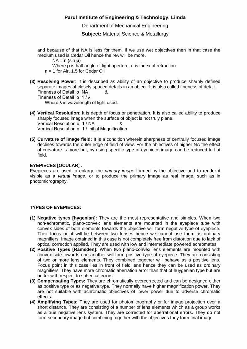
Parul Institute of Engineering amp Technology Limda
Department of Mechanical Engineering
Subject Material Science amp Metallurgy
and because of that NA is less for them If we use wet objectives then in that case the medium used is Cedar Oil hence the NA will be more
NA = n (sin μ) Where μ is half angle of light aperture n is index of refraction
n = 1 for Air 15 for Cedar Oil
(3) Resolving Power It is described as ability of an objective to produce sharply defined separate images of closely spaced details in an object It is also called fineness of detail Fineness of Detail α NA amp Fineness of Detail α 1 λ Where λ is wavelength of light used
(4) Vertical Resolution It is depth of focus or penetration It is also called ability to produce sharply focused image when the surface of object is not truly plane Vertical Resolution α 1 NA amp Vertical Resolution α 1 Initial Magnification
(5) Curvature of image field It is a condition wherein sharpness of centrally focused image declines towards the outer edge of field of view For the objectives of higher NA the effect of curvature is more but by using specific type of eyepiece image can be reduced to flat field
EYEPIECES [OCULAR] Eyepieces are used to enlarge the primary image formed by the objective and to render it visible as a virtual image or to produce the primary image as real image such as in photomicrography TYPES OF EYEPIECES (1) Negative types [hygenian] They are the most representative and simples When two
non-achromatic plano-convex lens elements are mounted in the eyepiece tube with convex sides of both elements towards the objective will form negative type of eyepiece Their focus point will lie between two lenses hence we cannot use them as ordinary magnifiers Image obtained in this case is not completely free from distortion due to lack of optical correction applied They are used with low and intermediate powered achromates
(2) Positive Types [Ramsden] When two plano-convex lens elements are mounted with convex side towards one another will form positive type of eyepiece They are consisting of two or more lens elements They combined together will behave as a positive lens Focus point in this case lies in front of field lens hence they can be used as ordinary magnifiers They have more chromatic aberration error than that of huygenian type but are better with respect to spherical errors
(3) Compensating Types They are chromatically overcorrected and can be designed either as positive type or as negative type They normally have higher magnification power They are not suitable with achromatic objectives of lower power due to adverse chromatic effects
(4) Amplifying Types They are used for photomicrography or for image projection over a short distance They are consisting of a number of lens elements which as a group works as a true negative lens system They are corrected for aberrational errors They do not form secondary image but combining together with the objectives they form final image
Parul Institute of Engineering amp Technology Limda
Department of Mechanical Engineering
Subject Material Science amp Metallurgy
ILLUMINATION SYSTEMS
Bright field illumination It is condition of lighting that renders a dark image on a bright well-lit background field Un-etched area becomes dark This happens because the reflected light is recollected by the lenses while scattered light does not get recollected The objective here first serves as condensing system to the incident light beam and then forms image This is the conventional system by which micro-examinations are carried out
Dark field illumination It is exactly the reverse condition to bright field illumination Here bright image is rendered on dark background field The objective here is used for forming image only Here only scattered light is recollected while reflected light rays are blocked This produces very strong image contrast Though this system is capable to reveal the details which are not possible by bright field system it is very difficult for out photo-microscopy
PRACTICAL CONTENTS
1) Study the operating principle of Metallurgical Microscope with the help of Ray Diagram
2) Understand various optical errors 3) Study various types of Objectives amp Eyepieces 4) Understand the illumination system and types 5) Study the important specification and capabilities of Microscope amp related computer
aided system we have QUESTIONS
1) Explain the working principle of Metallurgical Microscope with the help of Ray Diagram
2) Identify different important parts of Microscope and tabulate them mentioning their main functions
3) Explain different errors related to the objectives 4) Explain following properties of Objective briefly (Mention mathematical relations
existing between them if any) a) Magnifying Power b) Resolving Power c) Numerical Power d) Vertical Resolution
5) Explain various Objectives with their main feature 6) Explain various Eyepieces with their main feature 7) Differentiate between Dark field amp Bright field illuminations 8) List the important specifications of the Metallurgical Microscope you have studied and
explain the usefulness of computer aided system we have
REFERENCE 1) Introduction to Physical Metallurgy By Sydney H Avner 2) Principles of Metallographic Laboratory Practices By GLKehl
MARKS OBTAINED SIGNATURE OF FACULTY DATE
Parul Institute of Engineering amp Technology Limda
Department of Mechanical Engineering
Subject Material Science amp Metallurgy
Practical No 03
Specimen Preparation for Micro examination
OBJECTIVE To study procedure of specimen preparation for microscopic examination INTRODUCTION A little can be learned regarding the structural characteristics of a metal by microscopic examination unless the surface that is to be examined is first prepared according to more or less rigid and precise procedures With the use of modern metallurgical microscope and precision optical parts where the obtainable resolution may be as great as a fraction of the wavelength of the light used to illuminate the specimen it is evident that perfect specimen preparation is of the greatest importance Improper preparation is likely to remove all important inclusions erode grain boundaries of temper hardened steel specimens ultimately producing a structure superficially at least which upon micro-examination will appear entirely different from that which is truly representative and characteristic of metal Obviously an examination of such a prepared specimen will lead only to erroneous interpretations and unreliable conclusions PRACTICAL CONTENTS 1) Determine the appropriate location and orientation of the specimen to be cut 2) Mounting the specimen if required 3) If the specimen to be observed is too uneven or with burrs etc achieve plane surface by
either filling or grinding on coarse grade emery paper 4) Take emery papers from coarse to finer abrasive grid (ie 10 20 30 amp 40) The emery is
placed on any clean hard level surface The specimen is rubbed back and forth across the entire length of paper under moderately applied pressure While being ground the specimen is held so that the new finer scratches being introduced on the surface are approximately at right angles to the old scratches resulting from previous flattening operation Switch over to next finer grade and repeat the same procedure
5) Now for better surface finish go to the polishing wheel The polishing wheel mounted cloth is rotated at appropriate speed and the specimen is moved continuously from the center to the periphery of the polishing wheel with moderate pressure
6) Select suitable etchant for the specimen and carry out the etching 7) Immediately after etching wash the specimen under running water and dry it with alcohol 8) Set the microscope with suitable selection of eye piece and objective for the desired
magnification
QUESTIONS 1) What is metallography Briefly explain its importance in Metallurgy 2) What is the basic difference between low grade no emery paper and high grade no
emery paper in the intermediate polishing process 3) What is an etchant Why etching is required List at least three name of etchant used for
different material 4) List the instruments and accessories you have used for preparing the sample along with
their specification details
Parul Institute of Engineering amp Technology Limda
Department of Mechanical Engineering
Subject Material Science amp Metallurgy
REFERENCE
1) Introduction to Physical Metallurgy By Sydney H Avner 2) Principles of Metallographic Laboratory Practices By GLKehi 3) Material Science ndash By OPKhanna 4) Material Science and Engineering ndash By William D Calliater Jr
MARKS OBTAINED SIGNATURE OF FACULTY DATE
Parul Institute of Engineering amp Technology Limda
Department of Mechanical Engineering
Subject Material Science amp Metallurgy
Practical No 04
Micro-Examination of Standard Specimen
OBJECTIVE To understand procedure and relevance of Micro-Examination INTRODUCTION Microexamination is study of internal structure of a material ie microstructure which can be carried out by light microscopy or electron microscopy An observation of microstructure in a microscope will show size and shape of grains and the size shape and distribution of various phases and inclusions and segregations These structural characteristics have great effect on mechanical properties of a material The microstructure will reveal the mechanical and thermal treatment of the material and it may be possible to predict the expected behavior under a given set of conditions PRACTICAL CONTENTS
1) Select the etchant required as per the specimen 2) Carry out etching 3) Immediately after etching wash the specimen under running water and dry it
with alcohol 4) Set the microscope with suitable selection of eye piece and objective for the
desired magnification 5) Sketch the microstructure observed
QUESTIONS
1) Record the microstructure observed in microscope with the aid of schematic diagram
2) Explain the impact of microstructure on various properties of materials REFERENCE
1) Introduction to Physical Metallurgy By Sydney H Avner 2) Principles of Metallographic Laboratory Practices By GLKehl 3) Material Science ndash By OPKhanna
MARKS OBTAINED SIGNATURE OF FACULTY DATE
Parul Institute of Engineering amp Technology Limda
Department of Mechanical Engineering
Subject Material Science amp Metallurgy
Practical No 05
Demonstration of heat treatment of steel
OBJECTIVE To study of Fe ndash C system demonstrate different heat treatment processes show the effect of different quenching media (Oil water and Brine) on the hardness of steel INTRODUCTION
According to the functional requirements of the component different engineering components need different hardness for their long service life Different quenching media generate different final microstructures (like coarse pearlite fine pearlite bainite martensite etc) and thus give different hardness values So the type of quenching media and the cooling rate both decide the final microstructure To derive the suitable hardness material technologists must know the effect of the quenching
Parul Institute of Engineering amp Technology Limda
Department of Mechanical Engineering
Subject Material Science amp Metallurgy
medium and cooling rate on the hardness of steel Knowledge of generating different hardness is of great help in industries for the manufacture of components like gears cams shafts axles pins etc to increase their service life THEORY Quenching which means drastic(rapid) cooling always gives high hardness in ferrous systems (metal involving iron) because of mechanism of allotropic transformation suppression Mechanism of heat removal during quenching is grouped into three stages 1) Vapour Blanket Stage Here the quenching medium (Oil Water or Brine)
vaporizes at the metal surface due to the high temperature and a thin film of vapour called vapour blanket surrounds the hot metal Presence of vapour retards the heat transfer process and hence the rate of cooling is relatively low
2) Vapour Transport Cooling Rate Here metal has cooled a temperature where
vapour blanket is no longer stable Because of absence of vapour between metal and liquid heat transfer rate increases and cooling rate is maximum
3) Liquid Cooling Stage Here the metal reaches the temperature of boiling point of
quenching medium Heat given by the hot metal is utilized in boiling the liquid In this stage cooling rate is lowest
To avoid cracks distortion and warpage quenching medium should show high initial cooling rate to avoid transformation in the nose region of the TTT curve followed by slow cooling rate through out the low temperature range Rise in temperature of quenching medium due to immersion of the component should be controlled by selecting the proper volume of quenching medium along with necessary cooling arrangement so that heat transfer rate gets maintained the level desired PRACTICAL CONTENTS 1) Measure the initial hardness of the given specimen on Rockwell Hardness Tester 2) Load these specimens in the furnace and heat them to the hardening temperature
for 20 to 30 minute 3) Quench these specimens in oil water and brine respectively 4) Measure the hardness of each of them after cooling
QUESTIONS 1) Draw the Fe ndash Fe3C diagram with all major transformations 2) What is soaking time State its importance 3) Enlist various heat treatment processes 4) What is the necessity of studying the effect of quenching media
Parul Institute of Engineering amp Technology Limda
Department of Mechanical Engineering
Subject Material Science amp Metallurgy
5) What should be the nature of quenching media to avoid cracks distortion or warpage of component being hardened
REFERENCE 1) Introduction to physical metallurgy Sydney H Avner 2) Physical Metallurgy principles Reed Hill 3) Materials science and engineering William D Callister Jr
MARKS OBTAINED SIGNATURE OF FACULTY DATE
Parul Institute of Engineering amp Technology Limda
Department of Mechanical Engineering
Subject Material Science amp Metallurgy
Practical No 06
Study of powder metallurgy OBJECTIVE To understand various processes of powder metallurgy INTRODUCTION
Powder metallurgy is the process of blending fine powdered materials pressing them into a desired shape or form (compacting) and then heating the compressed material in a controlled atmosphere to bond the material (sintering) The powder metallurgy process generally consists of four basic steps (1) powder manufacture (2) powder blending(3) compacting (4) sintering Compacting is generally performed at room temperature and the elevated-temperature process of sintering is usually conducted at atmospheric pressure Optional secondary processing often follows to obtain special properties or enhanced precision[1]
Two main techniques used to form and consolidate the powder are sintering and metal injection molding Recent developments have made it possible to use rapid manufacturing techniques which use the metal powder for the products Because with this technique the powder is melted and not sintered better mechanical strength can be accomplished
PRACTICAL CONTENTS QUESTIONS REFERENCE
1) Introduction to Poeder Metallurgy By A K Sinha 2) Principles of Metallographic Laboratory Practices By GLKehl 3) Material Science ndash By OPKhanna
MARKS OBTAINED SIGNATURE OF FACULTY DATE
Parul Institute of Engineering amp Technology Limda
Department of Mechanical Engineering
Subject Material Science amp Metallurgy
Practical No 07
Ultrasonic Test
OBJECTIVE To understand principle procedure and capabilities of ultrasonic test INTRODUCTION The basic principle of the method is detecting the change in attenuation of sound energy (ultrasonic) ndash the change being caused by a flaw or the material In this test ultrasonic sound waves (above the audible range) capable of penetrating and medium of appreciable thickness at speeds of several thousand metersec are used The frequency may range from 1 to 15 MHz There will be changes in probing medium when there is a flaw which will be detected and indicated by the equipment ndash the ultrasonic flaw detector The pulse-echo technique is widely preferred This employs a single probe (transducer) as transmitter and receiver of ultrasonic waves The ultrasonic waves with high frequency are generated by piezoelectric effect When these high frequency waves enter the material being tested part of it is reflected and converted back to an electrical impulse This electrical impulse is amplified and rendered visible as an indicator or pip on the screen of the oscilloscope When the sound wave reaches the other side of the other side of the material it is reflected back and shows as another pip on the screen further to the right of the first pip (pulse) If there is a flaw between the front and back surfaces of the material (ie the thickness) it will show as a third pip (pulse) on the screen between the two indications or pulses Since the indications on the oscilloscope screen measure the elapsed time between reflection of the pulse from the front and back surfaces the distance between indications is a measure of thickness of the material The location of a defect can therefore be accurately determined from the location on the screen Angle probes may be used to detect flaws which are not oriented perpendicular to the direction of propagation of sound waves PRACTICAL CONTENTS 1) With the help of the manual of the equipment get acquainted with the operating details of
ultrasonic flaw detector 2) Calibrate the instrument using IIW-V1 Block 3) Scan the given samples and report the indications in following manner
Sr No CRT Reading Length of defect from probing surface (mm)
4) Sketch the samples you have scanned illustrating the flaws in it
Parul Institute of Engineering amp Technology Limda
Department of Mechanical Engineering
Subject Material Science amp Metallurgy
QUESTIONS 1) Briefly explain the principle of Ultrasonic Testing State various methods of conducting UT
and sketch the operating principle of the method you have used in lab 2) Evaluate UT with other with respect to other NDT methods you know 3) Illustrate internal construction of following probes and mention the selection criteria for
each of them a) Normal Probe b) Dual Crystal Probe c) Angle Probe
4) Explain briefly following terminology in context of UT a) Attenuation b) Dead Zone c) Near Zone d) Couplants e) Acoustic impedance f) Sensitivity
REFERENCE 1) Introduction to physical metallurgy Sydney H Avner 2) Instrument manual available in Lab 3) Material Science And Engineering William D Callister 4) Practical Non-Destructive Testing Raj Baldev Jayakumar T amp Thavasimuthu M
MARKS OBTAINED SIGNATURE OF FACULTY DATE
Parul Institute of Engineering amp Technology Limda
Department of Mechanical Engineering
Subject Material Science amp Metallurgy
Practical No 08
Magnetic Particle Test
OBJECTIVE To understand principle procedure amp capabilities of Magnetic Particle Test INTRODUCTION The magnetic particle test is one of the most powerful surface andor subsurface crack detection methods for Ferromagnetic Materials The principle of the operation is that when a component under test is magnetized discontinuities which lie in a direction generally transverse to the direction of magnetic field will cause a leakage field to be formed If leakage field is strong enough its presence and therefore the discontinuity is detected by use of finely divided ferromagnetic particles applied over the surface Some of the ferromagnetic particles are influence by leakage field and form an outline of the discontinuity called as an indication The indication may give about size shape and location of the flaw PRACTICAL CONTENTS 1) Determine the setting up procedure parameters 2) Clean the specimen thoroughly Degreasing may be carried out by spirit or
trichloroethylene bath 3) Setup the equipment for the nature of the defect to be detected (cracks surface
subsurface porosity etc) Based on it select the electrical current source 4) Apply magnetic particles 5) Perform the test in different orientations of magnetic field application and record
the nature and extent of indication with and without fluorescent powder 6) Demagnetize the work piece and check for results QUESTIONS 1) Briefly explain the principle and procedure of MPT with neat sketches 2) Comment on applications advantages and limitations of MPT
REFERENCE 1) Introduction to physical metallurgy Sydney H Avner 2) Instrument manual available in Lab
MARKS OBTAINED SIGNATURE OF FACULTY DATE
Parul Institute of Engineering amp Technology Limda
Department of Mechanical Engineering
Subject Material Science amp Metallurgy
Practical No 09
Dye Penetrant Test OBJECTIVE To understand principle procedure amp capabilities of Liquid Dye Penetrant Test INTRODUCTION Dye penetrant test is essentially useful in detecting minute discontinuities such as cracks shrinkages and porosity that are open to the surface Parts to be tested are treated with a penetrant Penetrant is usually light oil-like liquids which is applied by dipping spraying or brushing or in some other convenient manner The liquid penetrant is drawn into cracks and other discontinuities by strong capillary action After the penetrant ahs had time to seep in the portion remaining on the surface is removed by wiping or washing This leaves the penetrant in all surface-connected discontinuities The pest part is now treated with a dry powder or a suspension of powder in a liquid This powder or developer acts like a sponge drawing the penetrant from the defect and enlarging the size of the area of penetrant indication PRACTICAL CONTENTS
1) Prepare the surface to be investigated and make it free from dirt and grease 2) Apply cleaner allow some time so that surface gets dried 3) Spray dye penetrant on the surface and allow some time (usually 3 to 5 min varies
from 2 min to few days) 4) Wipe out excess penetrant (This may be carried out by a light spray of cleaner and
wiping it out) 5) Apply developer and observer indications 6) If needed the developer once again 7) Observe the defect
QUESTIONS 1) What types of properties of the dye are required to perform the LPT accurately 2) Why the developer is used in LPT 3) List the limitation amp capabilities of LPT 4) Mention the IS No for DPT 5) Draw the neat sketch of sample amp indications
REFERENCE 1) Introduction to physical metallurgy Sydney H Avner 2) Practical Non Destructive Testing Raj Baldev Jayakumar T Thavasimuthu M 3) httpwwwndt-edorgEducationResourcesCommunityCollegeRadiographycc_
rad_indexhtm
MARKS OBTAINED SIGNATURE OF FACULTY DATE
Parul Institute of Engineering amp Technology Limda
Department of Mechanical Engineering
Subject Material Science amp Metallurgy
Practical No 10
Study of Eddy current test amp Radiography test
OBJECTIVE To understand principle procedure amp capabilities of Eddy current test amp Radiography test INTRODUCTION
Eddy-current testing uses electromagnetic induction to detect flaws in conductive materials There are several limitations among them only conductive materials can be tested the surface of the material must be accessible the finish of the material may cause bad readings the depth of penetration into the material is limited by the materials conductivity and flaws that lie parallel to the probe may be undetectable
Eddy current inspection is one of several NDT methods that use the principal of ldquoelectromagnetismrdquo as the basis for conducting examinations Several other methods such as Remote Field Testing (RFT) Flux Leakage and Barkhausen Noise also use this principle
Eddy currents are created through a process called electromagnetic induction When alternating current is applied to the conductor such as copper wire a magnetic field develops in and around the conductor This magnetic field expands as the alternating current rises to maximum and collapses as the current is reduced to zero If another electrical conductor is brought into the close proximity to this changing magnetic field current will be induced in this second conductor Eddy currents are induced electrical currents that flow in a circular path They get their name from ldquoeddiesrdquo that are formed when a liquid or gas flows in a circular path around obstacles when conditions are right
In a standard eddy current testing a circular coil carrying current is placed in proximity to the test specimen (which must be electrically conductive)The alternating current in the coil generates changing magnetic field which interacts with test specimen and generates eddy currentVariations in the phase and magnitude of these eddy currents can be monitored using a second receiver coil or by measuring changes to the current flowing in the primary excitation coil Variations in the electrical conductivity or magnetic permeability of the test object or the presence of any flaws will cause a change in eddy current and a corresponding change in the phase and amplitude of the measured current This is the basis of standard (flat coil) eddy current inspection the most widely used eddy current technique
However eddy-current testing can detect very small cracks in or near the surface of the material the surfaces need minimal preparation and physically complex geometries can be investigated It is also useful for making electrical conductivity and coating thickness measurements
Radiation Safety
Ionizing radiation is an extremely important NDT tool but it can pose a hazard to human health For this reason special precautions must be observed when using and working around ionizing radiation The possession of radioactive materials and use of radiation producing devices in the United States is governed by strict regulatory controls The primary regulatory authority for most types and uses of radioactive materials is the federal Nuclear Regulatory Commission (NRC) However more than half of the states in the US have entered into
Parul Institute of Engineering amp Technology Limda
Department of Mechanical Engineering
Subject Material Science amp Metallurgy
agreement with the NRC to assume regulatory control of radioactive material use within their borders As part of the agreement process the states must adopt and enforce regulations comparable to those found in Title 10 of the Code of Federal Regulations Regulations for control of radioactive material used in Iowa are found in Chapter 136C of the Iowa Code
For most situations the types and maximum quantities of radioactive materials possessed the manner in which they may be used and the individuals authorized to use radioactive materials are stipulated in the form of a specific license from the appropriate regulatory authority In Iowa this authority is the Iowa Department of Public Health However for certain institutions which routinely use large quantities of numerous types of radioactive materials the exact quantities of materials and details of use may not be specified in the license Instead the license grants the institution the authority and responsibility for setting the specific requirements for radioactive material use within its facilities These licensees are termed broadscope and require a Radiation Safety Committee and usually a full-time Radiation Safety Officer
PRACTICAL CONTENTS
1) Prepare the surface to be investigated and make it free from dirt and grease 2) Observe the defect
QUESTIONS 1) Explain principle of Eddy current test 2) Explain principle of Radiography test 3) Enlist merits amp demerits of Eddy current test amp Radiography test 4) What precaution one has to take before doing radiography test why
REFERENCE 1) Introduction to physical metallurgy Sydney H Avner 2) Practical Non Destructive Testing Raj Baldev Jayakumar T Thavasimuthu M 3) httpwwwndt-edorgEducationResourcesCommunityCollegeRadiographycc_
rad_indexhtm
MARKS OBTAINED SIGNATURE OF FACULTY DATE
Parul Institute of Engineering amp Technology Limda
Department of Mechanical Engineering
Subject Material Science amp Metallurgy
Practical No 11
Jominy Hardenability Test OBJECTIVE To understand the concept of hardenability and its relevance to heat treatment procedure to be adopted in practice INTRODUCTION Hardenability is the property that determines the depth and distribution of hardness induced by quenching in a ferrous alloy The Jominy test together with the appropriate data is ideally suited for predicting the hardness at a particular location within a section of any given size regardless of the steel from which the section is made It establishes a correlation between the cooling rate and corresponding distance from the quenched end for each of the test bars This relationship is the fundamental one and remains substantially unaltered so long as the Jominy procedure is strictly adhered to It is possible through this correlation to predict hardness within any given shaped object once the cooling rate is known at the location of interest Such cooling rates within the objects may be determined experimentally or may be obtained by reference to appropriate published data if the size shape and heat treatment of the object correspond to the condition under which data were obtained PRACTICAL CONTENTS 1) Understand the theory and relevance of hardenability 2) Heat the specimen to the austenitizing temperature and soak it at this temperature
for 30 minutes 3) After soaking a test specimen is removed rapidly and placed on a quenching
fixture 4) The water tap shall be opened as soon as the test piece is fixed in position and the
time of spraying shall be at least 10 minutes After this time the cooling of the test specimen is removed rapidly and placed on a quenching fixture
5) Two flats for measuring the hardness shall be ground on the surface 1800 apart and parallel to the axis of the test piece along its entire length They should be 04 to 05 mm deep shall be ground with an abundant supply of coolant so as to prevent any heating likely to modify the microstructure of the quenched test piece
6) Rockwell hardness measurements are made at an interval of 15 mm along the longitudinal center line of the flat surface
7) Record the observations as under
Specimen Material Hardness before test Temperature amp Socking Time
Sr No Distance from the quenched end (mm) Hardness (HRC)
Parul Institute of Engineering amp Technology Limda
Department of Mechanical Engineering
Subject Material Science amp Metallurgy
8) Plot the graph of Distance vs Hardness
QUESTIONS 1) Draw the neat diagram of standard specimen and practical set up 2) What is hardenability What are the factors on which hardenability depends 3) What kind of transformation is desirable to have a greater hardenability 4) Differentiate between hardness and hardenability 5) What is the grain structure of martensite 6) How is hardenability curve useful 7) Why it is necessary to cool the test specimen of Jominy hardenability test while
grinding two flat surfaces for measurement purpose REFERENCE 1) Introduction to physical metallurgy Sydney H Avner 2) Physical Metallurgy Principles Reed Hill 3) Material Science And Engineering William D Callister
MARKS OBTAINED SIGNATURE OF FACULTY DATE
Parul Institute of Engineering amp Technology Limda
Department of Mechanical Engineering
Subject Material Science amp Metallurgy
ILLUMINATION SYSTEMS
Bright field illumination It is condition of lighting that renders a dark image on a bright well-lit background field Un-etched area becomes dark This happens because the reflected light is recollected by the lenses while scattered light does not get recollected The objective here first serves as condensing system to the incident light beam and then forms image This is the conventional system by which micro-examinations are carried out
Dark field illumination It is exactly the reverse condition to bright field illumination Here bright image is rendered on dark background field The objective here is used for forming image only Here only scattered light is recollected while reflected light rays are blocked This produces very strong image contrast Though this system is capable to reveal the details which are not possible by bright field system it is very difficult for out photo-microscopy
PRACTICAL CONTENTS
1) Study the operating principle of Metallurgical Microscope with the help of Ray Diagram
2) Understand various optical errors 3) Study various types of Objectives amp Eyepieces 4) Understand the illumination system and types 5) Study the important specification and capabilities of Microscope amp related computer
aided system we have QUESTIONS
1) Explain the working principle of Metallurgical Microscope with the help of Ray Diagram
2) Identify different important parts of Microscope and tabulate them mentioning their main functions
3) Explain different errors related to the objectives 4) Explain following properties of Objective briefly (Mention mathematical relations
existing between them if any) a) Magnifying Power b) Resolving Power c) Numerical Power d) Vertical Resolution
5) Explain various Objectives with their main feature 6) Explain various Eyepieces with their main feature 7) Differentiate between Dark field amp Bright field illuminations 8) List the important specifications of the Metallurgical Microscope you have studied and
explain the usefulness of computer aided system we have
REFERENCE 1) Introduction to Physical Metallurgy By Sydney H Avner 2) Principles of Metallographic Laboratory Practices By GLKehl
MARKS OBTAINED SIGNATURE OF FACULTY DATE
Parul Institute of Engineering amp Technology Limda
Department of Mechanical Engineering
Subject Material Science amp Metallurgy
Practical No 03
Specimen Preparation for Micro examination
OBJECTIVE To study procedure of specimen preparation for microscopic examination INTRODUCTION A little can be learned regarding the structural characteristics of a metal by microscopic examination unless the surface that is to be examined is first prepared according to more or less rigid and precise procedures With the use of modern metallurgical microscope and precision optical parts where the obtainable resolution may be as great as a fraction of the wavelength of the light used to illuminate the specimen it is evident that perfect specimen preparation is of the greatest importance Improper preparation is likely to remove all important inclusions erode grain boundaries of temper hardened steel specimens ultimately producing a structure superficially at least which upon micro-examination will appear entirely different from that which is truly representative and characteristic of metal Obviously an examination of such a prepared specimen will lead only to erroneous interpretations and unreliable conclusions PRACTICAL CONTENTS 1) Determine the appropriate location and orientation of the specimen to be cut 2) Mounting the specimen if required 3) If the specimen to be observed is too uneven or with burrs etc achieve plane surface by
either filling or grinding on coarse grade emery paper 4) Take emery papers from coarse to finer abrasive grid (ie 10 20 30 amp 40) The emery is
placed on any clean hard level surface The specimen is rubbed back and forth across the entire length of paper under moderately applied pressure While being ground the specimen is held so that the new finer scratches being introduced on the surface are approximately at right angles to the old scratches resulting from previous flattening operation Switch over to next finer grade and repeat the same procedure
5) Now for better surface finish go to the polishing wheel The polishing wheel mounted cloth is rotated at appropriate speed and the specimen is moved continuously from the center to the periphery of the polishing wheel with moderate pressure
6) Select suitable etchant for the specimen and carry out the etching 7) Immediately after etching wash the specimen under running water and dry it with alcohol 8) Set the microscope with suitable selection of eye piece and objective for the desired
magnification
QUESTIONS 1) What is metallography Briefly explain its importance in Metallurgy 2) What is the basic difference between low grade no emery paper and high grade no
emery paper in the intermediate polishing process 3) What is an etchant Why etching is required List at least three name of etchant used for
different material 4) List the instruments and accessories you have used for preparing the sample along with
their specification details
Parul Institute of Engineering amp Technology Limda
Department of Mechanical Engineering
Subject Material Science amp Metallurgy
REFERENCE
1) Introduction to Physical Metallurgy By Sydney H Avner 2) Principles of Metallographic Laboratory Practices By GLKehi 3) Material Science ndash By OPKhanna 4) Material Science and Engineering ndash By William D Calliater Jr
MARKS OBTAINED SIGNATURE OF FACULTY DATE
Parul Institute of Engineering amp Technology Limda
Department of Mechanical Engineering
Subject Material Science amp Metallurgy
Practical No 04
Micro-Examination of Standard Specimen
OBJECTIVE To understand procedure and relevance of Micro-Examination INTRODUCTION Microexamination is study of internal structure of a material ie microstructure which can be carried out by light microscopy or electron microscopy An observation of microstructure in a microscope will show size and shape of grains and the size shape and distribution of various phases and inclusions and segregations These structural characteristics have great effect on mechanical properties of a material The microstructure will reveal the mechanical and thermal treatment of the material and it may be possible to predict the expected behavior under a given set of conditions PRACTICAL CONTENTS
1) Select the etchant required as per the specimen 2) Carry out etching 3) Immediately after etching wash the specimen under running water and dry it
with alcohol 4) Set the microscope with suitable selection of eye piece and objective for the
desired magnification 5) Sketch the microstructure observed
QUESTIONS
1) Record the microstructure observed in microscope with the aid of schematic diagram
2) Explain the impact of microstructure on various properties of materials REFERENCE
1) Introduction to Physical Metallurgy By Sydney H Avner 2) Principles of Metallographic Laboratory Practices By GLKehl 3) Material Science ndash By OPKhanna
MARKS OBTAINED SIGNATURE OF FACULTY DATE
Parul Institute of Engineering amp Technology Limda
Department of Mechanical Engineering
Subject Material Science amp Metallurgy
Practical No 05
Demonstration of heat treatment of steel
OBJECTIVE To study of Fe ndash C system demonstrate different heat treatment processes show the effect of different quenching media (Oil water and Brine) on the hardness of steel INTRODUCTION
According to the functional requirements of the component different engineering components need different hardness for their long service life Different quenching media generate different final microstructures (like coarse pearlite fine pearlite bainite martensite etc) and thus give different hardness values So the type of quenching media and the cooling rate both decide the final microstructure To derive the suitable hardness material technologists must know the effect of the quenching
Parul Institute of Engineering amp Technology Limda
Department of Mechanical Engineering
Subject Material Science amp Metallurgy
medium and cooling rate on the hardness of steel Knowledge of generating different hardness is of great help in industries for the manufacture of components like gears cams shafts axles pins etc to increase their service life THEORY Quenching which means drastic(rapid) cooling always gives high hardness in ferrous systems (metal involving iron) because of mechanism of allotropic transformation suppression Mechanism of heat removal during quenching is grouped into three stages 1) Vapour Blanket Stage Here the quenching medium (Oil Water or Brine)
vaporizes at the metal surface due to the high temperature and a thin film of vapour called vapour blanket surrounds the hot metal Presence of vapour retards the heat transfer process and hence the rate of cooling is relatively low
2) Vapour Transport Cooling Rate Here metal has cooled a temperature where
vapour blanket is no longer stable Because of absence of vapour between metal and liquid heat transfer rate increases and cooling rate is maximum
3) Liquid Cooling Stage Here the metal reaches the temperature of boiling point of
quenching medium Heat given by the hot metal is utilized in boiling the liquid In this stage cooling rate is lowest
To avoid cracks distortion and warpage quenching medium should show high initial cooling rate to avoid transformation in the nose region of the TTT curve followed by slow cooling rate through out the low temperature range Rise in temperature of quenching medium due to immersion of the component should be controlled by selecting the proper volume of quenching medium along with necessary cooling arrangement so that heat transfer rate gets maintained the level desired PRACTICAL CONTENTS 1) Measure the initial hardness of the given specimen on Rockwell Hardness Tester 2) Load these specimens in the furnace and heat them to the hardening temperature
for 20 to 30 minute 3) Quench these specimens in oil water and brine respectively 4) Measure the hardness of each of them after cooling
QUESTIONS 1) Draw the Fe ndash Fe3C diagram with all major transformations 2) What is soaking time State its importance 3) Enlist various heat treatment processes 4) What is the necessity of studying the effect of quenching media
Parul Institute of Engineering amp Technology Limda
Department of Mechanical Engineering
Subject Material Science amp Metallurgy
5) What should be the nature of quenching media to avoid cracks distortion or warpage of component being hardened
REFERENCE 1) Introduction to physical metallurgy Sydney H Avner 2) Physical Metallurgy principles Reed Hill 3) Materials science and engineering William D Callister Jr
MARKS OBTAINED SIGNATURE OF FACULTY DATE
Parul Institute of Engineering amp Technology Limda
Department of Mechanical Engineering
Subject Material Science amp Metallurgy
Practical No 06
Study of powder metallurgy OBJECTIVE To understand various processes of powder metallurgy INTRODUCTION
Powder metallurgy is the process of blending fine powdered materials pressing them into a desired shape or form (compacting) and then heating the compressed material in a controlled atmosphere to bond the material (sintering) The powder metallurgy process generally consists of four basic steps (1) powder manufacture (2) powder blending(3) compacting (4) sintering Compacting is generally performed at room temperature and the elevated-temperature process of sintering is usually conducted at atmospheric pressure Optional secondary processing often follows to obtain special properties or enhanced precision[1]
Two main techniques used to form and consolidate the powder are sintering and metal injection molding Recent developments have made it possible to use rapid manufacturing techniques which use the metal powder for the products Because with this technique the powder is melted and not sintered better mechanical strength can be accomplished
PRACTICAL CONTENTS QUESTIONS REFERENCE
1) Introduction to Poeder Metallurgy By A K Sinha 2) Principles of Metallographic Laboratory Practices By GLKehl 3) Material Science ndash By OPKhanna
MARKS OBTAINED SIGNATURE OF FACULTY DATE
Parul Institute of Engineering amp Technology Limda
Department of Mechanical Engineering
Subject Material Science amp Metallurgy
Practical No 07
Ultrasonic Test
OBJECTIVE To understand principle procedure and capabilities of ultrasonic test INTRODUCTION The basic principle of the method is detecting the change in attenuation of sound energy (ultrasonic) ndash the change being caused by a flaw or the material In this test ultrasonic sound waves (above the audible range) capable of penetrating and medium of appreciable thickness at speeds of several thousand metersec are used The frequency may range from 1 to 15 MHz There will be changes in probing medium when there is a flaw which will be detected and indicated by the equipment ndash the ultrasonic flaw detector The pulse-echo technique is widely preferred This employs a single probe (transducer) as transmitter and receiver of ultrasonic waves The ultrasonic waves with high frequency are generated by piezoelectric effect When these high frequency waves enter the material being tested part of it is reflected and converted back to an electrical impulse This electrical impulse is amplified and rendered visible as an indicator or pip on the screen of the oscilloscope When the sound wave reaches the other side of the other side of the material it is reflected back and shows as another pip on the screen further to the right of the first pip (pulse) If there is a flaw between the front and back surfaces of the material (ie the thickness) it will show as a third pip (pulse) on the screen between the two indications or pulses Since the indications on the oscilloscope screen measure the elapsed time between reflection of the pulse from the front and back surfaces the distance between indications is a measure of thickness of the material The location of a defect can therefore be accurately determined from the location on the screen Angle probes may be used to detect flaws which are not oriented perpendicular to the direction of propagation of sound waves PRACTICAL CONTENTS 1) With the help of the manual of the equipment get acquainted with the operating details of
ultrasonic flaw detector 2) Calibrate the instrument using IIW-V1 Block 3) Scan the given samples and report the indications in following manner
Sr No CRT Reading Length of defect from probing surface (mm)
4) Sketch the samples you have scanned illustrating the flaws in it
Parul Institute of Engineering amp Technology Limda
Department of Mechanical Engineering
Subject Material Science amp Metallurgy
QUESTIONS 1) Briefly explain the principle of Ultrasonic Testing State various methods of conducting UT
and sketch the operating principle of the method you have used in lab 2) Evaluate UT with other with respect to other NDT methods you know 3) Illustrate internal construction of following probes and mention the selection criteria for
each of them a) Normal Probe b) Dual Crystal Probe c) Angle Probe
4) Explain briefly following terminology in context of UT a) Attenuation b) Dead Zone c) Near Zone d) Couplants e) Acoustic impedance f) Sensitivity
REFERENCE 1) Introduction to physical metallurgy Sydney H Avner 2) Instrument manual available in Lab 3) Material Science And Engineering William D Callister 4) Practical Non-Destructive Testing Raj Baldev Jayakumar T amp Thavasimuthu M
MARKS OBTAINED SIGNATURE OF FACULTY DATE
Parul Institute of Engineering amp Technology Limda
Department of Mechanical Engineering
Subject Material Science amp Metallurgy
Practical No 08
Magnetic Particle Test
OBJECTIVE To understand principle procedure amp capabilities of Magnetic Particle Test INTRODUCTION The magnetic particle test is one of the most powerful surface andor subsurface crack detection methods for Ferromagnetic Materials The principle of the operation is that when a component under test is magnetized discontinuities which lie in a direction generally transverse to the direction of magnetic field will cause a leakage field to be formed If leakage field is strong enough its presence and therefore the discontinuity is detected by use of finely divided ferromagnetic particles applied over the surface Some of the ferromagnetic particles are influence by leakage field and form an outline of the discontinuity called as an indication The indication may give about size shape and location of the flaw PRACTICAL CONTENTS 1) Determine the setting up procedure parameters 2) Clean the specimen thoroughly Degreasing may be carried out by spirit or
trichloroethylene bath 3) Setup the equipment for the nature of the defect to be detected (cracks surface
subsurface porosity etc) Based on it select the electrical current source 4) Apply magnetic particles 5) Perform the test in different orientations of magnetic field application and record
the nature and extent of indication with and without fluorescent powder 6) Demagnetize the work piece and check for results QUESTIONS 1) Briefly explain the principle and procedure of MPT with neat sketches 2) Comment on applications advantages and limitations of MPT
REFERENCE 1) Introduction to physical metallurgy Sydney H Avner 2) Instrument manual available in Lab
MARKS OBTAINED SIGNATURE OF FACULTY DATE
Parul Institute of Engineering amp Technology Limda
Department of Mechanical Engineering
Subject Material Science amp Metallurgy
Practical No 09
Dye Penetrant Test OBJECTIVE To understand principle procedure amp capabilities of Liquid Dye Penetrant Test INTRODUCTION Dye penetrant test is essentially useful in detecting minute discontinuities such as cracks shrinkages and porosity that are open to the surface Parts to be tested are treated with a penetrant Penetrant is usually light oil-like liquids which is applied by dipping spraying or brushing or in some other convenient manner The liquid penetrant is drawn into cracks and other discontinuities by strong capillary action After the penetrant ahs had time to seep in the portion remaining on the surface is removed by wiping or washing This leaves the penetrant in all surface-connected discontinuities The pest part is now treated with a dry powder or a suspension of powder in a liquid This powder or developer acts like a sponge drawing the penetrant from the defect and enlarging the size of the area of penetrant indication PRACTICAL CONTENTS
1) Prepare the surface to be investigated and make it free from dirt and grease 2) Apply cleaner allow some time so that surface gets dried 3) Spray dye penetrant on the surface and allow some time (usually 3 to 5 min varies
from 2 min to few days) 4) Wipe out excess penetrant (This may be carried out by a light spray of cleaner and
wiping it out) 5) Apply developer and observer indications 6) If needed the developer once again 7) Observe the defect
QUESTIONS 1) What types of properties of the dye are required to perform the LPT accurately 2) Why the developer is used in LPT 3) List the limitation amp capabilities of LPT 4) Mention the IS No for DPT 5) Draw the neat sketch of sample amp indications
REFERENCE 1) Introduction to physical metallurgy Sydney H Avner 2) Practical Non Destructive Testing Raj Baldev Jayakumar T Thavasimuthu M 3) httpwwwndt-edorgEducationResourcesCommunityCollegeRadiographycc_
rad_indexhtm
MARKS OBTAINED SIGNATURE OF FACULTY DATE
Parul Institute of Engineering amp Technology Limda
Department of Mechanical Engineering
Subject Material Science amp Metallurgy
Practical No 10
Study of Eddy current test amp Radiography test
OBJECTIVE To understand principle procedure amp capabilities of Eddy current test amp Radiography test INTRODUCTION
Eddy-current testing uses electromagnetic induction to detect flaws in conductive materials There are several limitations among them only conductive materials can be tested the surface of the material must be accessible the finish of the material may cause bad readings the depth of penetration into the material is limited by the materials conductivity and flaws that lie parallel to the probe may be undetectable
Eddy current inspection is one of several NDT methods that use the principal of ldquoelectromagnetismrdquo as the basis for conducting examinations Several other methods such as Remote Field Testing (RFT) Flux Leakage and Barkhausen Noise also use this principle
Eddy currents are created through a process called electromagnetic induction When alternating current is applied to the conductor such as copper wire a magnetic field develops in and around the conductor This magnetic field expands as the alternating current rises to maximum and collapses as the current is reduced to zero If another electrical conductor is brought into the close proximity to this changing magnetic field current will be induced in this second conductor Eddy currents are induced electrical currents that flow in a circular path They get their name from ldquoeddiesrdquo that are formed when a liquid or gas flows in a circular path around obstacles when conditions are right
In a standard eddy current testing a circular coil carrying current is placed in proximity to the test specimen (which must be electrically conductive)The alternating current in the coil generates changing magnetic field which interacts with test specimen and generates eddy currentVariations in the phase and magnitude of these eddy currents can be monitored using a second receiver coil or by measuring changes to the current flowing in the primary excitation coil Variations in the electrical conductivity or magnetic permeability of the test object or the presence of any flaws will cause a change in eddy current and a corresponding change in the phase and amplitude of the measured current This is the basis of standard (flat coil) eddy current inspection the most widely used eddy current technique
However eddy-current testing can detect very small cracks in or near the surface of the material the surfaces need minimal preparation and physically complex geometries can be investigated It is also useful for making electrical conductivity and coating thickness measurements
Radiation Safety
Ionizing radiation is an extremely important NDT tool but it can pose a hazard to human health For this reason special precautions must be observed when using and working around ionizing radiation The possession of radioactive materials and use of radiation producing devices in the United States is governed by strict regulatory controls The primary regulatory authority for most types and uses of radioactive materials is the federal Nuclear Regulatory Commission (NRC) However more than half of the states in the US have entered into
Parul Institute of Engineering amp Technology Limda
Department of Mechanical Engineering
Subject Material Science amp Metallurgy
agreement with the NRC to assume regulatory control of radioactive material use within their borders As part of the agreement process the states must adopt and enforce regulations comparable to those found in Title 10 of the Code of Federal Regulations Regulations for control of radioactive material used in Iowa are found in Chapter 136C of the Iowa Code
For most situations the types and maximum quantities of radioactive materials possessed the manner in which they may be used and the individuals authorized to use radioactive materials are stipulated in the form of a specific license from the appropriate regulatory authority In Iowa this authority is the Iowa Department of Public Health However for certain institutions which routinely use large quantities of numerous types of radioactive materials the exact quantities of materials and details of use may not be specified in the license Instead the license grants the institution the authority and responsibility for setting the specific requirements for radioactive material use within its facilities These licensees are termed broadscope and require a Radiation Safety Committee and usually a full-time Radiation Safety Officer
PRACTICAL CONTENTS
1) Prepare the surface to be investigated and make it free from dirt and grease 2) Observe the defect
QUESTIONS 1) Explain principle of Eddy current test 2) Explain principle of Radiography test 3) Enlist merits amp demerits of Eddy current test amp Radiography test 4) What precaution one has to take before doing radiography test why
REFERENCE 1) Introduction to physical metallurgy Sydney H Avner 2) Practical Non Destructive Testing Raj Baldev Jayakumar T Thavasimuthu M 3) httpwwwndt-edorgEducationResourcesCommunityCollegeRadiographycc_
rad_indexhtm
MARKS OBTAINED SIGNATURE OF FACULTY DATE
Parul Institute of Engineering amp Technology Limda
Department of Mechanical Engineering
Subject Material Science amp Metallurgy
Practical No 11
Jominy Hardenability Test OBJECTIVE To understand the concept of hardenability and its relevance to heat treatment procedure to be adopted in practice INTRODUCTION Hardenability is the property that determines the depth and distribution of hardness induced by quenching in a ferrous alloy The Jominy test together with the appropriate data is ideally suited for predicting the hardness at a particular location within a section of any given size regardless of the steel from which the section is made It establishes a correlation between the cooling rate and corresponding distance from the quenched end for each of the test bars This relationship is the fundamental one and remains substantially unaltered so long as the Jominy procedure is strictly adhered to It is possible through this correlation to predict hardness within any given shaped object once the cooling rate is known at the location of interest Such cooling rates within the objects may be determined experimentally or may be obtained by reference to appropriate published data if the size shape and heat treatment of the object correspond to the condition under which data were obtained PRACTICAL CONTENTS 1) Understand the theory and relevance of hardenability 2) Heat the specimen to the austenitizing temperature and soak it at this temperature
for 30 minutes 3) After soaking a test specimen is removed rapidly and placed on a quenching
fixture 4) The water tap shall be opened as soon as the test piece is fixed in position and the
time of spraying shall be at least 10 minutes After this time the cooling of the test specimen is removed rapidly and placed on a quenching fixture
5) Two flats for measuring the hardness shall be ground on the surface 1800 apart and parallel to the axis of the test piece along its entire length They should be 04 to 05 mm deep shall be ground with an abundant supply of coolant so as to prevent any heating likely to modify the microstructure of the quenched test piece
6) Rockwell hardness measurements are made at an interval of 15 mm along the longitudinal center line of the flat surface
7) Record the observations as under
Specimen Material Hardness before test Temperature amp Socking Time
Sr No Distance from the quenched end (mm) Hardness (HRC)
Parul Institute of Engineering amp Technology Limda
Department of Mechanical Engineering
Subject Material Science amp Metallurgy
8) Plot the graph of Distance vs Hardness
QUESTIONS 1) Draw the neat diagram of standard specimen and practical set up 2) What is hardenability What are the factors on which hardenability depends 3) What kind of transformation is desirable to have a greater hardenability 4) Differentiate between hardness and hardenability 5) What is the grain structure of martensite 6) How is hardenability curve useful 7) Why it is necessary to cool the test specimen of Jominy hardenability test while
grinding two flat surfaces for measurement purpose REFERENCE 1) Introduction to physical metallurgy Sydney H Avner 2) Physical Metallurgy Principles Reed Hill 3) Material Science And Engineering William D Callister
MARKS OBTAINED SIGNATURE OF FACULTY DATE

Parul Institute of Engineering amp Technology Limda
Department of Mechanical Engineering
Subject Material Science amp Metallurgy
Practical No 03
Specimen Preparation for Micro examination
OBJECTIVE To study procedure of specimen preparation for microscopic examination INTRODUCTION A little can be learned regarding the structural characteristics of a metal by microscopic examination unless the surface that is to be examined is first prepared according to more or less rigid and precise procedures With the use of modern metallurgical microscope and precision optical parts where the obtainable resolution may be as great as a fraction of the wavelength of the light used to illuminate the specimen it is evident that perfect specimen preparation is of the greatest importance Improper preparation is likely to remove all important inclusions erode grain boundaries of temper hardened steel specimens ultimately producing a structure superficially at least which upon micro-examination will appear entirely different from that which is truly representative and characteristic of metal Obviously an examination of such a prepared specimen will lead only to erroneous interpretations and unreliable conclusions PRACTICAL CONTENTS 1) Determine the appropriate location and orientation of the specimen to be cut 2) Mounting the specimen if required 3) If the specimen to be observed is too uneven or with burrs etc achieve plane surface by
either filling or grinding on coarse grade emery paper 4) Take emery papers from coarse to finer abrasive grid (ie 10 20 30 amp 40) The emery is
placed on any clean hard level surface The specimen is rubbed back and forth across the entire length of paper under moderately applied pressure While being ground the specimen is held so that the new finer scratches being introduced on the surface are approximately at right angles to the old scratches resulting from previous flattening operation Switch over to next finer grade and repeat the same procedure
5) Now for better surface finish go to the polishing wheel The polishing wheel mounted cloth is rotated at appropriate speed and the specimen is moved continuously from the center to the periphery of the polishing wheel with moderate pressure
6) Select suitable etchant for the specimen and carry out the etching 7) Immediately after etching wash the specimen under running water and dry it with alcohol 8) Set the microscope with suitable selection of eye piece and objective for the desired
magnification
QUESTIONS 1) What is metallography Briefly explain its importance in Metallurgy 2) What is the basic difference between low grade no emery paper and high grade no
emery paper in the intermediate polishing process 3) What is an etchant Why etching is required List at least three name of etchant used for
different material 4) List the instruments and accessories you have used for preparing the sample along with
their specification details
Parul Institute of Engineering amp Technology Limda
Department of Mechanical Engineering
Subject Material Science amp Metallurgy
REFERENCE
1) Introduction to Physical Metallurgy By Sydney H Avner 2) Principles of Metallographic Laboratory Practices By GLKehi 3) Material Science ndash By OPKhanna 4) Material Science and Engineering ndash By William D Calliater Jr
MARKS OBTAINED SIGNATURE OF FACULTY DATE
Parul Institute of Engineering amp Technology Limda
Department of Mechanical Engineering
Subject Material Science amp Metallurgy
Practical No 04
Micro-Examination of Standard Specimen
OBJECTIVE To understand procedure and relevance of Micro-Examination INTRODUCTION Microexamination is study of internal structure of a material ie microstructure which can be carried out by light microscopy or electron microscopy An observation of microstructure in a microscope will show size and shape of grains and the size shape and distribution of various phases and inclusions and segregations These structural characteristics have great effect on mechanical properties of a material The microstructure will reveal the mechanical and thermal treatment of the material and it may be possible to predict the expected behavior under a given set of conditions PRACTICAL CONTENTS
1) Select the etchant required as per the specimen 2) Carry out etching 3) Immediately after etching wash the specimen under running water and dry it
with alcohol 4) Set the microscope with suitable selection of eye piece and objective for the
desired magnification 5) Sketch the microstructure observed
QUESTIONS
1) Record the microstructure observed in microscope with the aid of schematic diagram
2) Explain the impact of microstructure on various properties of materials REFERENCE
1) Introduction to Physical Metallurgy By Sydney H Avner 2) Principles of Metallographic Laboratory Practices By GLKehl 3) Material Science ndash By OPKhanna
MARKS OBTAINED SIGNATURE OF FACULTY DATE
Parul Institute of Engineering amp Technology Limda
Department of Mechanical Engineering
Subject Material Science amp Metallurgy
Practical No 05
Demonstration of heat treatment of steel
OBJECTIVE To study of Fe ndash C system demonstrate different heat treatment processes show the effect of different quenching media (Oil water and Brine) on the hardness of steel INTRODUCTION
According to the functional requirements of the component different engineering components need different hardness for their long service life Different quenching media generate different final microstructures (like coarse pearlite fine pearlite bainite martensite etc) and thus give different hardness values So the type of quenching media and the cooling rate both decide the final microstructure To derive the suitable hardness material technologists must know the effect of the quenching
Parul Institute of Engineering amp Technology Limda
Department of Mechanical Engineering
Subject Material Science amp Metallurgy
medium and cooling rate on the hardness of steel Knowledge of generating different hardness is of great help in industries for the manufacture of components like gears cams shafts axles pins etc to increase their service life THEORY Quenching which means drastic(rapid) cooling always gives high hardness in ferrous systems (metal involving iron) because of mechanism of allotropic transformation suppression Mechanism of heat removal during quenching is grouped into three stages 1) Vapour Blanket Stage Here the quenching medium (Oil Water or Brine)
vaporizes at the metal surface due to the high temperature and a thin film of vapour called vapour blanket surrounds the hot metal Presence of vapour retards the heat transfer process and hence the rate of cooling is relatively low
2) Vapour Transport Cooling Rate Here metal has cooled a temperature where
vapour blanket is no longer stable Because of absence of vapour between metal and liquid heat transfer rate increases and cooling rate is maximum
3) Liquid Cooling Stage Here the metal reaches the temperature of boiling point of
quenching medium Heat given by the hot metal is utilized in boiling the liquid In this stage cooling rate is lowest
To avoid cracks distortion and warpage quenching medium should show high initial cooling rate to avoid transformation in the nose region of the TTT curve followed by slow cooling rate through out the low temperature range Rise in temperature of quenching medium due to immersion of the component should be controlled by selecting the proper volume of quenching medium along with necessary cooling arrangement so that heat transfer rate gets maintained the level desired PRACTICAL CONTENTS 1) Measure the initial hardness of the given specimen on Rockwell Hardness Tester 2) Load these specimens in the furnace and heat them to the hardening temperature
for 20 to 30 minute 3) Quench these specimens in oil water and brine respectively 4) Measure the hardness of each of them after cooling
QUESTIONS 1) Draw the Fe ndash Fe3C diagram with all major transformations 2) What is soaking time State its importance 3) Enlist various heat treatment processes 4) What is the necessity of studying the effect of quenching media
Parul Institute of Engineering amp Technology Limda
Department of Mechanical Engineering
Subject Material Science amp Metallurgy
5) What should be the nature of quenching media to avoid cracks distortion or warpage of component being hardened
REFERENCE 1) Introduction to physical metallurgy Sydney H Avner 2) Physical Metallurgy principles Reed Hill 3) Materials science and engineering William D Callister Jr
MARKS OBTAINED SIGNATURE OF FACULTY DATE
Parul Institute of Engineering amp Technology Limda
Department of Mechanical Engineering
Subject Material Science amp Metallurgy
Practical No 06
Study of powder metallurgy OBJECTIVE To understand various processes of powder metallurgy INTRODUCTION
Powder metallurgy is the process of blending fine powdered materials pressing them into a desired shape or form (compacting) and then heating the compressed material in a controlled atmosphere to bond the material (sintering) The powder metallurgy process generally consists of four basic steps (1) powder manufacture (2) powder blending(3) compacting (4) sintering Compacting is generally performed at room temperature and the elevated-temperature process of sintering is usually conducted at atmospheric pressure Optional secondary processing often follows to obtain special properties or enhanced precision[1]
Two main techniques used to form and consolidate the powder are sintering and metal injection molding Recent developments have made it possible to use rapid manufacturing techniques which use the metal powder for the products Because with this technique the powder is melted and not sintered better mechanical strength can be accomplished
PRACTICAL CONTENTS QUESTIONS REFERENCE
1) Introduction to Poeder Metallurgy By A K Sinha 2) Principles of Metallographic Laboratory Practices By GLKehl 3) Material Science ndash By OPKhanna
MARKS OBTAINED SIGNATURE OF FACULTY DATE
Parul Institute of Engineering amp Technology Limda
Department of Mechanical Engineering
Subject Material Science amp Metallurgy
Practical No 07
Ultrasonic Test
OBJECTIVE To understand principle procedure and capabilities of ultrasonic test INTRODUCTION The basic principle of the method is detecting the change in attenuation of sound energy (ultrasonic) ndash the change being caused by a flaw or the material In this test ultrasonic sound waves (above the audible range) capable of penetrating and medium of appreciable thickness at speeds of several thousand metersec are used The frequency may range from 1 to 15 MHz There will be changes in probing medium when there is a flaw which will be detected and indicated by the equipment ndash the ultrasonic flaw detector The pulse-echo technique is widely preferred This employs a single probe (transducer) as transmitter and receiver of ultrasonic waves The ultrasonic waves with high frequency are generated by piezoelectric effect When these high frequency waves enter the material being tested part of it is reflected and converted back to an electrical impulse This electrical impulse is amplified and rendered visible as an indicator or pip on the screen of the oscilloscope When the sound wave reaches the other side of the other side of the material it is reflected back and shows as another pip on the screen further to the right of the first pip (pulse) If there is a flaw between the front and back surfaces of the material (ie the thickness) it will show as a third pip (pulse) on the screen between the two indications or pulses Since the indications on the oscilloscope screen measure the elapsed time between reflection of the pulse from the front and back surfaces the distance between indications is a measure of thickness of the material The location of a defect can therefore be accurately determined from the location on the screen Angle probes may be used to detect flaws which are not oriented perpendicular to the direction of propagation of sound waves PRACTICAL CONTENTS 1) With the help of the manual of the equipment get acquainted with the operating details of
ultrasonic flaw detector 2) Calibrate the instrument using IIW-V1 Block 3) Scan the given samples and report the indications in following manner
Sr No CRT Reading Length of defect from probing surface (mm)
4) Sketch the samples you have scanned illustrating the flaws in it
Parul Institute of Engineering amp Technology Limda
Department of Mechanical Engineering
Subject Material Science amp Metallurgy
QUESTIONS 1) Briefly explain the principle of Ultrasonic Testing State various methods of conducting UT
and sketch the operating principle of the method you have used in lab 2) Evaluate UT with other with respect to other NDT methods you know 3) Illustrate internal construction of following probes and mention the selection criteria for
each of them a) Normal Probe b) Dual Crystal Probe c) Angle Probe
4) Explain briefly following terminology in context of UT a) Attenuation b) Dead Zone c) Near Zone d) Couplants e) Acoustic impedance f) Sensitivity
REFERENCE 1) Introduction to physical metallurgy Sydney H Avner 2) Instrument manual available in Lab 3) Material Science And Engineering William D Callister 4) Practical Non-Destructive Testing Raj Baldev Jayakumar T amp Thavasimuthu M
MARKS OBTAINED SIGNATURE OF FACULTY DATE
Parul Institute of Engineering amp Technology Limda
Department of Mechanical Engineering
Subject Material Science amp Metallurgy
Practical No 08
Magnetic Particle Test
OBJECTIVE To understand principle procedure amp capabilities of Magnetic Particle Test INTRODUCTION The magnetic particle test is one of the most powerful surface andor subsurface crack detection methods for Ferromagnetic Materials The principle of the operation is that when a component under test is magnetized discontinuities which lie in a direction generally transverse to the direction of magnetic field will cause a leakage field to be formed If leakage field is strong enough its presence and therefore the discontinuity is detected by use of finely divided ferromagnetic particles applied over the surface Some of the ferromagnetic particles are influence by leakage field and form an outline of the discontinuity called as an indication The indication may give about size shape and location of the flaw PRACTICAL CONTENTS 1) Determine the setting up procedure parameters 2) Clean the specimen thoroughly Degreasing may be carried out by spirit or
trichloroethylene bath 3) Setup the equipment for the nature of the defect to be detected (cracks surface
subsurface porosity etc) Based on it select the electrical current source 4) Apply magnetic particles 5) Perform the test in different orientations of magnetic field application and record
the nature and extent of indication with and without fluorescent powder 6) Demagnetize the work piece and check for results QUESTIONS 1) Briefly explain the principle and procedure of MPT with neat sketches 2) Comment on applications advantages and limitations of MPT
REFERENCE 1) Introduction to physical metallurgy Sydney H Avner 2) Instrument manual available in Lab
MARKS OBTAINED SIGNATURE OF FACULTY DATE
Parul Institute of Engineering amp Technology Limda
Department of Mechanical Engineering
Subject Material Science amp Metallurgy
Practical No 09
Dye Penetrant Test OBJECTIVE To understand principle procedure amp capabilities of Liquid Dye Penetrant Test INTRODUCTION Dye penetrant test is essentially useful in detecting minute discontinuities such as cracks shrinkages and porosity that are open to the surface Parts to be tested are treated with a penetrant Penetrant is usually light oil-like liquids which is applied by dipping spraying or brushing or in some other convenient manner The liquid penetrant is drawn into cracks and other discontinuities by strong capillary action After the penetrant ahs had time to seep in the portion remaining on the surface is removed by wiping or washing This leaves the penetrant in all surface-connected discontinuities The pest part is now treated with a dry powder or a suspension of powder in a liquid This powder or developer acts like a sponge drawing the penetrant from the defect and enlarging the size of the area of penetrant indication PRACTICAL CONTENTS
1) Prepare the surface to be investigated and make it free from dirt and grease 2) Apply cleaner allow some time so that surface gets dried 3) Spray dye penetrant on the surface and allow some time (usually 3 to 5 min varies
from 2 min to few days) 4) Wipe out excess penetrant (This may be carried out by a light spray of cleaner and
wiping it out) 5) Apply developer and observer indications 6) If needed the developer once again 7) Observe the defect
QUESTIONS 1) What types of properties of the dye are required to perform the LPT accurately 2) Why the developer is used in LPT 3) List the limitation amp capabilities of LPT 4) Mention the IS No for DPT 5) Draw the neat sketch of sample amp indications
REFERENCE 1) Introduction to physical metallurgy Sydney H Avner 2) Practical Non Destructive Testing Raj Baldev Jayakumar T Thavasimuthu M 3) httpwwwndt-edorgEducationResourcesCommunityCollegeRadiographycc_
rad_indexhtm
MARKS OBTAINED SIGNATURE OF FACULTY DATE
Parul Institute of Engineering amp Technology Limda
Department of Mechanical Engineering
Subject Material Science amp Metallurgy
Practical No 10
Study of Eddy current test amp Radiography test
OBJECTIVE To understand principle procedure amp capabilities of Eddy current test amp Radiography test INTRODUCTION
Eddy-current testing uses electromagnetic induction to detect flaws in conductive materials There are several limitations among them only conductive materials can be tested the surface of the material must be accessible the finish of the material may cause bad readings the depth of penetration into the material is limited by the materials conductivity and flaws that lie parallel to the probe may be undetectable
Eddy current inspection is one of several NDT methods that use the principal of ldquoelectromagnetismrdquo as the basis for conducting examinations Several other methods such as Remote Field Testing (RFT) Flux Leakage and Barkhausen Noise also use this principle
Eddy currents are created through a process called electromagnetic induction When alternating current is applied to the conductor such as copper wire a magnetic field develops in and around the conductor This magnetic field expands as the alternating current rises to maximum and collapses as the current is reduced to zero If another electrical conductor is brought into the close proximity to this changing magnetic field current will be induced in this second conductor Eddy currents are induced electrical currents that flow in a circular path They get their name from ldquoeddiesrdquo that are formed when a liquid or gas flows in a circular path around obstacles when conditions are right
In a standard eddy current testing a circular coil carrying current is placed in proximity to the test specimen (which must be electrically conductive)The alternating current in the coil generates changing magnetic field which interacts with test specimen and generates eddy currentVariations in the phase and magnitude of these eddy currents can be monitored using a second receiver coil or by measuring changes to the current flowing in the primary excitation coil Variations in the electrical conductivity or magnetic permeability of the test object or the presence of any flaws will cause a change in eddy current and a corresponding change in the phase and amplitude of the measured current This is the basis of standard (flat coil) eddy current inspection the most widely used eddy current technique
However eddy-current testing can detect very small cracks in or near the surface of the material the surfaces need minimal preparation and physically complex geometries can be investigated It is also useful for making electrical conductivity and coating thickness measurements
Radiation Safety
Ionizing radiation is an extremely important NDT tool but it can pose a hazard to human health For this reason special precautions must be observed when using and working around ionizing radiation The possession of radioactive materials and use of radiation producing devices in the United States is governed by strict regulatory controls The primary regulatory authority for most types and uses of radioactive materials is the federal Nuclear Regulatory Commission (NRC) However more than half of the states in the US have entered into
Parul Institute of Engineering amp Technology Limda
Department of Mechanical Engineering
Subject Material Science amp Metallurgy
agreement with the NRC to assume regulatory control of radioactive material use within their borders As part of the agreement process the states must adopt and enforce regulations comparable to those found in Title 10 of the Code of Federal Regulations Regulations for control of radioactive material used in Iowa are found in Chapter 136C of the Iowa Code
For most situations the types and maximum quantities of radioactive materials possessed the manner in which they may be used and the individuals authorized to use radioactive materials are stipulated in the form of a specific license from the appropriate regulatory authority In Iowa this authority is the Iowa Department of Public Health However for certain institutions which routinely use large quantities of numerous types of radioactive materials the exact quantities of materials and details of use may not be specified in the license Instead the license grants the institution the authority and responsibility for setting the specific requirements for radioactive material use within its facilities These licensees are termed broadscope and require a Radiation Safety Committee and usually a full-time Radiation Safety Officer
PRACTICAL CONTENTS
1) Prepare the surface to be investigated and make it free from dirt and grease 2) Observe the defect
QUESTIONS 1) Explain principle of Eddy current test 2) Explain principle of Radiography test 3) Enlist merits amp demerits of Eddy current test amp Radiography test 4) What precaution one has to take before doing radiography test why
REFERENCE 1) Introduction to physical metallurgy Sydney H Avner 2) Practical Non Destructive Testing Raj Baldev Jayakumar T Thavasimuthu M 3) httpwwwndt-edorgEducationResourcesCommunityCollegeRadiographycc_
rad_indexhtm
MARKS OBTAINED SIGNATURE OF FACULTY DATE
Parul Institute of Engineering amp Technology Limda
Department of Mechanical Engineering
Subject Material Science amp Metallurgy
Practical No 11
Jominy Hardenability Test OBJECTIVE To understand the concept of hardenability and its relevance to heat treatment procedure to be adopted in practice INTRODUCTION Hardenability is the property that determines the depth and distribution of hardness induced by quenching in a ferrous alloy The Jominy test together with the appropriate data is ideally suited for predicting the hardness at a particular location within a section of any given size regardless of the steel from which the section is made It establishes a correlation between the cooling rate and corresponding distance from the quenched end for each of the test bars This relationship is the fundamental one and remains substantially unaltered so long as the Jominy procedure is strictly adhered to It is possible through this correlation to predict hardness within any given shaped object once the cooling rate is known at the location of interest Such cooling rates within the objects may be determined experimentally or may be obtained by reference to appropriate published data if the size shape and heat treatment of the object correspond to the condition under which data were obtained PRACTICAL CONTENTS 1) Understand the theory and relevance of hardenability 2) Heat the specimen to the austenitizing temperature and soak it at this temperature
for 30 minutes 3) After soaking a test specimen is removed rapidly and placed on a quenching
fixture 4) The water tap shall be opened as soon as the test piece is fixed in position and the
time of spraying shall be at least 10 minutes After this time the cooling of the test specimen is removed rapidly and placed on a quenching fixture
5) Two flats for measuring the hardness shall be ground on the surface 1800 apart and parallel to the axis of the test piece along its entire length They should be 04 to 05 mm deep shall be ground with an abundant supply of coolant so as to prevent any heating likely to modify the microstructure of the quenched test piece
6) Rockwell hardness measurements are made at an interval of 15 mm along the longitudinal center line of the flat surface
7) Record the observations as under
Specimen Material Hardness before test Temperature amp Socking Time
Sr No Distance from the quenched end (mm) Hardness (HRC)
Parul Institute of Engineering amp Technology Limda
Department of Mechanical Engineering
Subject Material Science amp Metallurgy
8) Plot the graph of Distance vs Hardness
QUESTIONS 1) Draw the neat diagram of standard specimen and practical set up 2) What is hardenability What are the factors on which hardenability depends 3) What kind of transformation is desirable to have a greater hardenability 4) Differentiate between hardness and hardenability 5) What is the grain structure of martensite 6) How is hardenability curve useful 7) Why it is necessary to cool the test specimen of Jominy hardenability test while
grinding two flat surfaces for measurement purpose REFERENCE 1) Introduction to physical metallurgy Sydney H Avner 2) Physical Metallurgy Principles Reed Hill 3) Material Science And Engineering William D Callister
MARKS OBTAINED SIGNATURE OF FACULTY DATE
Parul Institute of Engineering amp Technology Limda
Department of Mechanical Engineering
Subject Material Science amp Metallurgy
Practical No 04
Micro-Examination of Standard Specimen
OBJECTIVE To understand procedure and relevance of Micro-Examination INTRODUCTION Microexamination is study of internal structure of a material ie microstructure which can be carried out by light microscopy or electron microscopy An observation of microstructure in a microscope will show size and shape of grains and the size shape and distribution of various phases and inclusions and segregations These structural characteristics have great effect on mechanical properties of a material The microstructure will reveal the mechanical and thermal treatment of the material and it may be possible to predict the expected behavior under a given set of conditions PRACTICAL CONTENTS
1) Select the etchant required as per the specimen 2) Carry out etching 3) Immediately after etching wash the specimen under running water and dry it
with alcohol 4) Set the microscope with suitable selection of eye piece and objective for the
desired magnification 5) Sketch the microstructure observed
QUESTIONS
1) Record the microstructure observed in microscope with the aid of schematic diagram
2) Explain the impact of microstructure on various properties of materials REFERENCE
1) Introduction to Physical Metallurgy By Sydney H Avner 2) Principles of Metallographic Laboratory Practices By GLKehl 3) Material Science ndash By OPKhanna
MARKS OBTAINED SIGNATURE OF FACULTY DATE
Parul Institute of Engineering amp Technology Limda
Department of Mechanical Engineering
Subject Material Science amp Metallurgy
Practical No 05
Demonstration of heat treatment of steel
OBJECTIVE To study of Fe ndash C system demonstrate different heat treatment processes show the effect of different quenching media (Oil water and Brine) on the hardness of steel INTRODUCTION
According to the functional requirements of the component different engineering components need different hardness for their long service life Different quenching media generate different final microstructures (like coarse pearlite fine pearlite bainite martensite etc) and thus give different hardness values So the type of quenching media and the cooling rate both decide the final microstructure To derive the suitable hardness material technologists must know the effect of the quenching
Parul Institute of Engineering amp Technology Limda
Department of Mechanical Engineering
Subject Material Science amp Metallurgy
medium and cooling rate on the hardness of steel Knowledge of generating different hardness is of great help in industries for the manufacture of components like gears cams shafts axles pins etc to increase their service life THEORY Quenching which means drastic(rapid) cooling always gives high hardness in ferrous systems (metal involving iron) because of mechanism of allotropic transformation suppression Mechanism of heat removal during quenching is grouped into three stages 1) Vapour Blanket Stage Here the quenching medium (Oil Water or Brine)
vaporizes at the metal surface due to the high temperature and a thin film of vapour called vapour blanket surrounds the hot metal Presence of vapour retards the heat transfer process and hence the rate of cooling is relatively low
2) Vapour Transport Cooling Rate Here metal has cooled a temperature where
vapour blanket is no longer stable Because of absence of vapour between metal and liquid heat transfer rate increases and cooling rate is maximum
3) Liquid Cooling Stage Here the metal reaches the temperature of boiling point of
quenching medium Heat given by the hot metal is utilized in boiling the liquid In this stage cooling rate is lowest
To avoid cracks distortion and warpage quenching medium should show high initial cooling rate to avoid transformation in the nose region of the TTT curve followed by slow cooling rate through out the low temperature range Rise in temperature of quenching medium due to immersion of the component should be controlled by selecting the proper volume of quenching medium along with necessary cooling arrangement so that heat transfer rate gets maintained the level desired PRACTICAL CONTENTS 1) Measure the initial hardness of the given specimen on Rockwell Hardness Tester 2) Load these specimens in the furnace and heat them to the hardening temperature
for 20 to 30 minute 3) Quench these specimens in oil water and brine respectively 4) Measure the hardness of each of them after cooling
QUESTIONS 1) Draw the Fe ndash Fe3C diagram with all major transformations 2) What is soaking time State its importance 3) Enlist various heat treatment processes 4) What is the necessity of studying the effect of quenching media
Parul Institute of Engineering amp Technology Limda
Department of Mechanical Engineering
Subject Material Science amp Metallurgy
5) What should be the nature of quenching media to avoid cracks distortion or warpage of component being hardened
REFERENCE 1) Introduction to physical metallurgy Sydney H Avner 2) Physical Metallurgy principles Reed Hill 3) Materials science and engineering William D Callister Jr
MARKS OBTAINED SIGNATURE OF FACULTY DATE
Parul Institute of Engineering amp Technology Limda
Department of Mechanical Engineering
Subject Material Science amp Metallurgy
Practical No 06
Study of powder metallurgy OBJECTIVE To understand various processes of powder metallurgy INTRODUCTION
Powder metallurgy is the process of blending fine powdered materials pressing them into a desired shape or form (compacting) and then heating the compressed material in a controlled atmosphere to bond the material (sintering) The powder metallurgy process generally consists of four basic steps (1) powder manufacture (2) powder blending(3) compacting (4) sintering Compacting is generally performed at room temperature and the elevated-temperature process of sintering is usually conducted at atmospheric pressure Optional secondary processing often follows to obtain special properties or enhanced precision[1]
Two main techniques used to form and consolidate the powder are sintering and metal injection molding Recent developments have made it possible to use rapid manufacturing techniques which use the metal powder for the products Because with this technique the powder is melted and not sintered better mechanical strength can be accomplished
PRACTICAL CONTENTS QUESTIONS REFERENCE
1) Introduction to Poeder Metallurgy By A K Sinha 2) Principles of Metallographic Laboratory Practices By GLKehl 3) Material Science ndash By OPKhanna
MARKS OBTAINED SIGNATURE OF FACULTY DATE
Parul Institute of Engineering amp Technology Limda
Department of Mechanical Engineering
Subject Material Science amp Metallurgy
Practical No 07
Ultrasonic Test
OBJECTIVE To understand principle procedure and capabilities of ultrasonic test INTRODUCTION The basic principle of the method is detecting the change in attenuation of sound energy (ultrasonic) ndash the change being caused by a flaw or the material In this test ultrasonic sound waves (above the audible range) capable of penetrating and medium of appreciable thickness at speeds of several thousand metersec are used The frequency may range from 1 to 15 MHz There will be changes in probing medium when there is a flaw which will be detected and indicated by the equipment ndash the ultrasonic flaw detector The pulse-echo technique is widely preferred This employs a single probe (transducer) as transmitter and receiver of ultrasonic waves The ultrasonic waves with high frequency are generated by piezoelectric effect When these high frequency waves enter the material being tested part of it is reflected and converted back to an electrical impulse This electrical impulse is amplified and rendered visible as an indicator or pip on the screen of the oscilloscope When the sound wave reaches the other side of the other side of the material it is reflected back and shows as another pip on the screen further to the right of the first pip (pulse) If there is a flaw between the front and back surfaces of the material (ie the thickness) it will show as a third pip (pulse) on the screen between the two indications or pulses Since the indications on the oscilloscope screen measure the elapsed time between reflection of the pulse from the front and back surfaces the distance between indications is a measure of thickness of the material The location of a defect can therefore be accurately determined from the location on the screen Angle probes may be used to detect flaws which are not oriented perpendicular to the direction of propagation of sound waves PRACTICAL CONTENTS 1) With the help of the manual of the equipment get acquainted with the operating details of
ultrasonic flaw detector 2) Calibrate the instrument using IIW-V1 Block 3) Scan the given samples and report the indications in following manner
Sr No CRT Reading Length of defect from probing surface (mm)
4) Sketch the samples you have scanned illustrating the flaws in it
Parul Institute of Engineering amp Technology Limda
Department of Mechanical Engineering
Subject Material Science amp Metallurgy
QUESTIONS 1) Briefly explain the principle of Ultrasonic Testing State various methods of conducting UT
and sketch the operating principle of the method you have used in lab 2) Evaluate UT with other with respect to other NDT methods you know 3) Illustrate internal construction of following probes and mention the selection criteria for
each of them a) Normal Probe b) Dual Crystal Probe c) Angle Probe
4) Explain briefly following terminology in context of UT a) Attenuation b) Dead Zone c) Near Zone d) Couplants e) Acoustic impedance f) Sensitivity
REFERENCE 1) Introduction to physical metallurgy Sydney H Avner 2) Instrument manual available in Lab 3) Material Science And Engineering William D Callister 4) Practical Non-Destructive Testing Raj Baldev Jayakumar T amp Thavasimuthu M
MARKS OBTAINED SIGNATURE OF FACULTY DATE
Parul Institute of Engineering amp Technology Limda
Department of Mechanical Engineering
Subject Material Science amp Metallurgy
Practical No 08
Magnetic Particle Test
OBJECTIVE To understand principle procedure amp capabilities of Magnetic Particle Test INTRODUCTION The magnetic particle test is one of the most powerful surface andor subsurface crack detection methods for Ferromagnetic Materials The principle of the operation is that when a component under test is magnetized discontinuities which lie in a direction generally transverse to the direction of magnetic field will cause a leakage field to be formed If leakage field is strong enough its presence and therefore the discontinuity is detected by use of finely divided ferromagnetic particles applied over the surface Some of the ferromagnetic particles are influence by leakage field and form an outline of the discontinuity called as an indication The indication may give about size shape and location of the flaw PRACTICAL CONTENTS 1) Determine the setting up procedure parameters 2) Clean the specimen thoroughly Degreasing may be carried out by spirit or
trichloroethylene bath 3) Setup the equipment for the nature of the defect to be detected (cracks surface
subsurface porosity etc) Based on it select the electrical current source 4) Apply magnetic particles 5) Perform the test in different orientations of magnetic field application and record
the nature and extent of indication with and without fluorescent powder 6) Demagnetize the work piece and check for results QUESTIONS 1) Briefly explain the principle and procedure of MPT with neat sketches 2) Comment on applications advantages and limitations of MPT
REFERENCE 1) Introduction to physical metallurgy Sydney H Avner 2) Instrument manual available in Lab
MARKS OBTAINED SIGNATURE OF FACULTY DATE
Parul Institute of Engineering amp Technology Limda
Department of Mechanical Engineering
Subject Material Science amp Metallurgy
Practical No 09
Dye Penetrant Test OBJECTIVE To understand principle procedure amp capabilities of Liquid Dye Penetrant Test INTRODUCTION Dye penetrant test is essentially useful in detecting minute discontinuities such as cracks shrinkages and porosity that are open to the surface Parts to be tested are treated with a penetrant Penetrant is usually light oil-like liquids which is applied by dipping spraying or brushing or in some other convenient manner The liquid penetrant is drawn into cracks and other discontinuities by strong capillary action After the penetrant ahs had time to seep in the portion remaining on the surface is removed by wiping or washing This leaves the penetrant in all surface-connected discontinuities The pest part is now treated with a dry powder or a suspension of powder in a liquid This powder or developer acts like a sponge drawing the penetrant from the defect and enlarging the size of the area of penetrant indication PRACTICAL CONTENTS
1) Prepare the surface to be investigated and make it free from dirt and grease 2) Apply cleaner allow some time so that surface gets dried 3) Spray dye penetrant on the surface and allow some time (usually 3 to 5 min varies
from 2 min to few days) 4) Wipe out excess penetrant (This may be carried out by a light spray of cleaner and
wiping it out) 5) Apply developer and observer indications 6) If needed the developer once again 7) Observe the defect
QUESTIONS 1) What types of properties of the dye are required to perform the LPT accurately 2) Why the developer is used in LPT 3) List the limitation amp capabilities of LPT 4) Mention the IS No for DPT 5) Draw the neat sketch of sample amp indications
REFERENCE 1) Introduction to physical metallurgy Sydney H Avner 2) Practical Non Destructive Testing Raj Baldev Jayakumar T Thavasimuthu M 3) httpwwwndt-edorgEducationResourcesCommunityCollegeRadiographycc_
rad_indexhtm
MARKS OBTAINED SIGNATURE OF FACULTY DATE
Parul Institute of Engineering amp Technology Limda
Department of Mechanical Engineering
Subject Material Science amp Metallurgy
Practical No 10
Study of Eddy current test amp Radiography test
OBJECTIVE To understand principle procedure amp capabilities of Eddy current test amp Radiography test INTRODUCTION
Eddy-current testing uses electromagnetic induction to detect flaws in conductive materials There are several limitations among them only conductive materials can be tested the surface of the material must be accessible the finish of the material may cause bad readings the depth of penetration into the material is limited by the materials conductivity and flaws that lie parallel to the probe may be undetectable
Eddy current inspection is one of several NDT methods that use the principal of ldquoelectromagnetismrdquo as the basis for conducting examinations Several other methods such as Remote Field Testing (RFT) Flux Leakage and Barkhausen Noise also use this principle
Eddy currents are created through a process called electromagnetic induction When alternating current is applied to the conductor such as copper wire a magnetic field develops in and around the conductor This magnetic field expands as the alternating current rises to maximum and collapses as the current is reduced to zero If another electrical conductor is brought into the close proximity to this changing magnetic field current will be induced in this second conductor Eddy currents are induced electrical currents that flow in a circular path They get their name from ldquoeddiesrdquo that are formed when a liquid or gas flows in a circular path around obstacles when conditions are right
In a standard eddy current testing a circular coil carrying current is placed in proximity to the test specimen (which must be electrically conductive)The alternating current in the coil generates changing magnetic field which interacts with test specimen and generates eddy currentVariations in the phase and magnitude of these eddy currents can be monitored using a second receiver coil or by measuring changes to the current flowing in the primary excitation coil Variations in the electrical conductivity or magnetic permeability of the test object or the presence of any flaws will cause a change in eddy current and a corresponding change in the phase and amplitude of the measured current This is the basis of standard (flat coil) eddy current inspection the most widely used eddy current technique
However eddy-current testing can detect very small cracks in or near the surface of the material the surfaces need minimal preparation and physically complex geometries can be investigated It is also useful for making electrical conductivity and coating thickness measurements
Radiation Safety
Ionizing radiation is an extremely important NDT tool but it can pose a hazard to human health For this reason special precautions must be observed when using and working around ionizing radiation The possession of radioactive materials and use of radiation producing devices in the United States is governed by strict regulatory controls The primary regulatory authority for most types and uses of radioactive materials is the federal Nuclear Regulatory Commission (NRC) However more than half of the states in the US have entered into
Parul Institute of Engineering amp Technology Limda
Department of Mechanical Engineering
Subject Material Science amp Metallurgy
agreement with the NRC to assume regulatory control of radioactive material use within their borders As part of the agreement process the states must adopt and enforce regulations comparable to those found in Title 10 of the Code of Federal Regulations Regulations for control of radioactive material used in Iowa are found in Chapter 136C of the Iowa Code
For most situations the types and maximum quantities of radioactive materials possessed the manner in which they may be used and the individuals authorized to use radioactive materials are stipulated in the form of a specific license from the appropriate regulatory authority In Iowa this authority is the Iowa Department of Public Health However for certain institutions which routinely use large quantities of numerous types of radioactive materials the exact quantities of materials and details of use may not be specified in the license Instead the license grants the institution the authority and responsibility for setting the specific requirements for radioactive material use within its facilities These licensees are termed broadscope and require a Radiation Safety Committee and usually a full-time Radiation Safety Officer
PRACTICAL CONTENTS
1) Prepare the surface to be investigated and make it free from dirt and grease 2) Observe the defect
QUESTIONS 1) Explain principle of Eddy current test 2) Explain principle of Radiography test 3) Enlist merits amp demerits of Eddy current test amp Radiography test 4) What precaution one has to take before doing radiography test why
REFERENCE 1) Introduction to physical metallurgy Sydney H Avner 2) Practical Non Destructive Testing Raj Baldev Jayakumar T Thavasimuthu M 3) httpwwwndt-edorgEducationResourcesCommunityCollegeRadiographycc_
rad_indexhtm
MARKS OBTAINED SIGNATURE OF FACULTY DATE
Parul Institute of Engineering amp Technology Limda
Department of Mechanical Engineering
Subject Material Science amp Metallurgy
Practical No 11
Jominy Hardenability Test OBJECTIVE To understand the concept of hardenability and its relevance to heat treatment procedure to be adopted in practice INTRODUCTION Hardenability is the property that determines the depth and distribution of hardness induced by quenching in a ferrous alloy The Jominy test together with the appropriate data is ideally suited for predicting the hardness at a particular location within a section of any given size regardless of the steel from which the section is made It establishes a correlation between the cooling rate and corresponding distance from the quenched end for each of the test bars This relationship is the fundamental one and remains substantially unaltered so long as the Jominy procedure is strictly adhered to It is possible through this correlation to predict hardness within any given shaped object once the cooling rate is known at the location of interest Such cooling rates within the objects may be determined experimentally or may be obtained by reference to appropriate published data if the size shape and heat treatment of the object correspond to the condition under which data were obtained PRACTICAL CONTENTS 1) Understand the theory and relevance of hardenability 2) Heat the specimen to the austenitizing temperature and soak it at this temperature
for 30 minutes 3) After soaking a test specimen is removed rapidly and placed on a quenching
fixture 4) The water tap shall be opened as soon as the test piece is fixed in position and the
time of spraying shall be at least 10 minutes After this time the cooling of the test specimen is removed rapidly and placed on a quenching fixture
5) Two flats for measuring the hardness shall be ground on the surface 1800 apart and parallel to the axis of the test piece along its entire length They should be 04 to 05 mm deep shall be ground with an abundant supply of coolant so as to prevent any heating likely to modify the microstructure of the quenched test piece
6) Rockwell hardness measurements are made at an interval of 15 mm along the longitudinal center line of the flat surface
7) Record the observations as under
Specimen Material Hardness before test Temperature amp Socking Time
Sr No Distance from the quenched end (mm) Hardness (HRC)
Parul Institute of Engineering amp Technology Limda
Department of Mechanical Engineering
Subject Material Science amp Metallurgy
8) Plot the graph of Distance vs Hardness
QUESTIONS 1) Draw the neat diagram of standard specimen and practical set up 2) What is hardenability What are the factors on which hardenability depends 3) What kind of transformation is desirable to have a greater hardenability 4) Differentiate between hardness and hardenability 5) What is the grain structure of martensite 6) How is hardenability curve useful 7) Why it is necessary to cool the test specimen of Jominy hardenability test while
grinding two flat surfaces for measurement purpose REFERENCE 1) Introduction to physical metallurgy Sydney H Avner 2) Physical Metallurgy Principles Reed Hill 3) Material Science And Engineering William D Callister
MARKS OBTAINED SIGNATURE OF FACULTY DATE
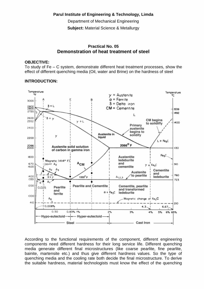
Parul Institute of Engineering amp Technology Limda
Department of Mechanical Engineering
Subject Material Science amp Metallurgy
Practical No 05
Demonstration of heat treatment of steel
OBJECTIVE To study of Fe ndash C system demonstrate different heat treatment processes show the effect of different quenching media (Oil water and Brine) on the hardness of steel INTRODUCTION
According to the functional requirements of the component different engineering components need different hardness for their long service life Different quenching media generate different final microstructures (like coarse pearlite fine pearlite bainite martensite etc) and thus give different hardness values So the type of quenching media and the cooling rate both decide the final microstructure To derive the suitable hardness material technologists must know the effect of the quenching
Parul Institute of Engineering amp Technology Limda
Department of Mechanical Engineering
Subject Material Science amp Metallurgy
medium and cooling rate on the hardness of steel Knowledge of generating different hardness is of great help in industries for the manufacture of components like gears cams shafts axles pins etc to increase their service life THEORY Quenching which means drastic(rapid) cooling always gives high hardness in ferrous systems (metal involving iron) because of mechanism of allotropic transformation suppression Mechanism of heat removal during quenching is grouped into three stages 1) Vapour Blanket Stage Here the quenching medium (Oil Water or Brine)
vaporizes at the metal surface due to the high temperature and a thin film of vapour called vapour blanket surrounds the hot metal Presence of vapour retards the heat transfer process and hence the rate of cooling is relatively low
2) Vapour Transport Cooling Rate Here metal has cooled a temperature where
vapour blanket is no longer stable Because of absence of vapour between metal and liquid heat transfer rate increases and cooling rate is maximum
3) Liquid Cooling Stage Here the metal reaches the temperature of boiling point of
quenching medium Heat given by the hot metal is utilized in boiling the liquid In this stage cooling rate is lowest
To avoid cracks distortion and warpage quenching medium should show high initial cooling rate to avoid transformation in the nose region of the TTT curve followed by slow cooling rate through out the low temperature range Rise in temperature of quenching medium due to immersion of the component should be controlled by selecting the proper volume of quenching medium along with necessary cooling arrangement so that heat transfer rate gets maintained the level desired PRACTICAL CONTENTS 1) Measure the initial hardness of the given specimen on Rockwell Hardness Tester 2) Load these specimens in the furnace and heat them to the hardening temperature
for 20 to 30 minute 3) Quench these specimens in oil water and brine respectively 4) Measure the hardness of each of them after cooling
QUESTIONS 1) Draw the Fe ndash Fe3C diagram with all major transformations 2) What is soaking time State its importance 3) Enlist various heat treatment processes 4) What is the necessity of studying the effect of quenching media
Parul Institute of Engineering amp Technology Limda
Department of Mechanical Engineering
Subject Material Science amp Metallurgy
5) What should be the nature of quenching media to avoid cracks distortion or warpage of component being hardened
REFERENCE 1) Introduction to physical metallurgy Sydney H Avner 2) Physical Metallurgy principles Reed Hill 3) Materials science and engineering William D Callister Jr
MARKS OBTAINED SIGNATURE OF FACULTY DATE
Parul Institute of Engineering amp Technology Limda
Department of Mechanical Engineering
Subject Material Science amp Metallurgy
Practical No 06
Study of powder metallurgy OBJECTIVE To understand various processes of powder metallurgy INTRODUCTION
Powder metallurgy is the process of blending fine powdered materials pressing them into a desired shape or form (compacting) and then heating the compressed material in a controlled atmosphere to bond the material (sintering) The powder metallurgy process generally consists of four basic steps (1) powder manufacture (2) powder blending(3) compacting (4) sintering Compacting is generally performed at room temperature and the elevated-temperature process of sintering is usually conducted at atmospheric pressure Optional secondary processing often follows to obtain special properties or enhanced precision[1]
Two main techniques used to form and consolidate the powder are sintering and metal injection molding Recent developments have made it possible to use rapid manufacturing techniques which use the metal powder for the products Because with this technique the powder is melted and not sintered better mechanical strength can be accomplished
PRACTICAL CONTENTS QUESTIONS REFERENCE
1) Introduction to Poeder Metallurgy By A K Sinha 2) Principles of Metallographic Laboratory Practices By GLKehl 3) Material Science ndash By OPKhanna
MARKS OBTAINED SIGNATURE OF FACULTY DATE
Parul Institute of Engineering amp Technology Limda
Department of Mechanical Engineering
Subject Material Science amp Metallurgy
Practical No 07
Ultrasonic Test
OBJECTIVE To understand principle procedure and capabilities of ultrasonic test INTRODUCTION The basic principle of the method is detecting the change in attenuation of sound energy (ultrasonic) ndash the change being caused by a flaw or the material In this test ultrasonic sound waves (above the audible range) capable of penetrating and medium of appreciable thickness at speeds of several thousand metersec are used The frequency may range from 1 to 15 MHz There will be changes in probing medium when there is a flaw which will be detected and indicated by the equipment ndash the ultrasonic flaw detector The pulse-echo technique is widely preferred This employs a single probe (transducer) as transmitter and receiver of ultrasonic waves The ultrasonic waves with high frequency are generated by piezoelectric effect When these high frequency waves enter the material being tested part of it is reflected and converted back to an electrical impulse This electrical impulse is amplified and rendered visible as an indicator or pip on the screen of the oscilloscope When the sound wave reaches the other side of the other side of the material it is reflected back and shows as another pip on the screen further to the right of the first pip (pulse) If there is a flaw between the front and back surfaces of the material (ie the thickness) it will show as a third pip (pulse) on the screen between the two indications or pulses Since the indications on the oscilloscope screen measure the elapsed time between reflection of the pulse from the front and back surfaces the distance between indications is a measure of thickness of the material The location of a defect can therefore be accurately determined from the location on the screen Angle probes may be used to detect flaws which are not oriented perpendicular to the direction of propagation of sound waves PRACTICAL CONTENTS 1) With the help of the manual of the equipment get acquainted with the operating details of
ultrasonic flaw detector 2) Calibrate the instrument using IIW-V1 Block 3) Scan the given samples and report the indications in following manner
Sr No CRT Reading Length of defect from probing surface (mm)
4) Sketch the samples you have scanned illustrating the flaws in it
Parul Institute of Engineering amp Technology Limda
Department of Mechanical Engineering
Subject Material Science amp Metallurgy
QUESTIONS 1) Briefly explain the principle of Ultrasonic Testing State various methods of conducting UT
and sketch the operating principle of the method you have used in lab 2) Evaluate UT with other with respect to other NDT methods you know 3) Illustrate internal construction of following probes and mention the selection criteria for
each of them a) Normal Probe b) Dual Crystal Probe c) Angle Probe
4) Explain briefly following terminology in context of UT a) Attenuation b) Dead Zone c) Near Zone d) Couplants e) Acoustic impedance f) Sensitivity
REFERENCE 1) Introduction to physical metallurgy Sydney H Avner 2) Instrument manual available in Lab 3) Material Science And Engineering William D Callister 4) Practical Non-Destructive Testing Raj Baldev Jayakumar T amp Thavasimuthu M
MARKS OBTAINED SIGNATURE OF FACULTY DATE
Parul Institute of Engineering amp Technology Limda
Department of Mechanical Engineering
Subject Material Science amp Metallurgy
Practical No 08
Magnetic Particle Test
OBJECTIVE To understand principle procedure amp capabilities of Magnetic Particle Test INTRODUCTION The magnetic particle test is one of the most powerful surface andor subsurface crack detection methods for Ferromagnetic Materials The principle of the operation is that when a component under test is magnetized discontinuities which lie in a direction generally transverse to the direction of magnetic field will cause a leakage field to be formed If leakage field is strong enough its presence and therefore the discontinuity is detected by use of finely divided ferromagnetic particles applied over the surface Some of the ferromagnetic particles are influence by leakage field and form an outline of the discontinuity called as an indication The indication may give about size shape and location of the flaw PRACTICAL CONTENTS 1) Determine the setting up procedure parameters 2) Clean the specimen thoroughly Degreasing may be carried out by spirit or
trichloroethylene bath 3) Setup the equipment for the nature of the defect to be detected (cracks surface
subsurface porosity etc) Based on it select the electrical current source 4) Apply magnetic particles 5) Perform the test in different orientations of magnetic field application and record
the nature and extent of indication with and without fluorescent powder 6) Demagnetize the work piece and check for results QUESTIONS 1) Briefly explain the principle and procedure of MPT with neat sketches 2) Comment on applications advantages and limitations of MPT
REFERENCE 1) Introduction to physical metallurgy Sydney H Avner 2) Instrument manual available in Lab
MARKS OBTAINED SIGNATURE OF FACULTY DATE
Parul Institute of Engineering amp Technology Limda
Department of Mechanical Engineering
Subject Material Science amp Metallurgy
Practical No 09
Dye Penetrant Test OBJECTIVE To understand principle procedure amp capabilities of Liquid Dye Penetrant Test INTRODUCTION Dye penetrant test is essentially useful in detecting minute discontinuities such as cracks shrinkages and porosity that are open to the surface Parts to be tested are treated with a penetrant Penetrant is usually light oil-like liquids which is applied by dipping spraying or brushing or in some other convenient manner The liquid penetrant is drawn into cracks and other discontinuities by strong capillary action After the penetrant ahs had time to seep in the portion remaining on the surface is removed by wiping or washing This leaves the penetrant in all surface-connected discontinuities The pest part is now treated with a dry powder or a suspension of powder in a liquid This powder or developer acts like a sponge drawing the penetrant from the defect and enlarging the size of the area of penetrant indication PRACTICAL CONTENTS
1) Prepare the surface to be investigated and make it free from dirt and grease 2) Apply cleaner allow some time so that surface gets dried 3) Spray dye penetrant on the surface and allow some time (usually 3 to 5 min varies
from 2 min to few days) 4) Wipe out excess penetrant (This may be carried out by a light spray of cleaner and
wiping it out) 5) Apply developer and observer indications 6) If needed the developer once again 7) Observe the defect
QUESTIONS 1) What types of properties of the dye are required to perform the LPT accurately 2) Why the developer is used in LPT 3) List the limitation amp capabilities of LPT 4) Mention the IS No for DPT 5) Draw the neat sketch of sample amp indications
REFERENCE 1) Introduction to physical metallurgy Sydney H Avner 2) Practical Non Destructive Testing Raj Baldev Jayakumar T Thavasimuthu M 3) httpwwwndt-edorgEducationResourcesCommunityCollegeRadiographycc_
rad_indexhtm
MARKS OBTAINED SIGNATURE OF FACULTY DATE
Parul Institute of Engineering amp Technology Limda
Department of Mechanical Engineering
Subject Material Science amp Metallurgy
Practical No 10
Study of Eddy current test amp Radiography test
OBJECTIVE To understand principle procedure amp capabilities of Eddy current test amp Radiography test INTRODUCTION
Eddy-current testing uses electromagnetic induction to detect flaws in conductive materials There are several limitations among them only conductive materials can be tested the surface of the material must be accessible the finish of the material may cause bad readings the depth of penetration into the material is limited by the materials conductivity and flaws that lie parallel to the probe may be undetectable
Eddy current inspection is one of several NDT methods that use the principal of ldquoelectromagnetismrdquo as the basis for conducting examinations Several other methods such as Remote Field Testing (RFT) Flux Leakage and Barkhausen Noise also use this principle
Eddy currents are created through a process called electromagnetic induction When alternating current is applied to the conductor such as copper wire a magnetic field develops in and around the conductor This magnetic field expands as the alternating current rises to maximum and collapses as the current is reduced to zero If another electrical conductor is brought into the close proximity to this changing magnetic field current will be induced in this second conductor Eddy currents are induced electrical currents that flow in a circular path They get their name from ldquoeddiesrdquo that are formed when a liquid or gas flows in a circular path around obstacles when conditions are right
In a standard eddy current testing a circular coil carrying current is placed in proximity to the test specimen (which must be electrically conductive)The alternating current in the coil generates changing magnetic field which interacts with test specimen and generates eddy currentVariations in the phase and magnitude of these eddy currents can be monitored using a second receiver coil or by measuring changes to the current flowing in the primary excitation coil Variations in the electrical conductivity or magnetic permeability of the test object or the presence of any flaws will cause a change in eddy current and a corresponding change in the phase and amplitude of the measured current This is the basis of standard (flat coil) eddy current inspection the most widely used eddy current technique
However eddy-current testing can detect very small cracks in or near the surface of the material the surfaces need minimal preparation and physically complex geometries can be investigated It is also useful for making electrical conductivity and coating thickness measurements
Radiation Safety
Ionizing radiation is an extremely important NDT tool but it can pose a hazard to human health For this reason special precautions must be observed when using and working around ionizing radiation The possession of radioactive materials and use of radiation producing devices in the United States is governed by strict regulatory controls The primary regulatory authority for most types and uses of radioactive materials is the federal Nuclear Regulatory Commission (NRC) However more than half of the states in the US have entered into
Parul Institute of Engineering amp Technology Limda
Department of Mechanical Engineering
Subject Material Science amp Metallurgy
agreement with the NRC to assume regulatory control of radioactive material use within their borders As part of the agreement process the states must adopt and enforce regulations comparable to those found in Title 10 of the Code of Federal Regulations Regulations for control of radioactive material used in Iowa are found in Chapter 136C of the Iowa Code
For most situations the types and maximum quantities of radioactive materials possessed the manner in which they may be used and the individuals authorized to use radioactive materials are stipulated in the form of a specific license from the appropriate regulatory authority In Iowa this authority is the Iowa Department of Public Health However for certain institutions which routinely use large quantities of numerous types of radioactive materials the exact quantities of materials and details of use may not be specified in the license Instead the license grants the institution the authority and responsibility for setting the specific requirements for radioactive material use within its facilities These licensees are termed broadscope and require a Radiation Safety Committee and usually a full-time Radiation Safety Officer
PRACTICAL CONTENTS
1) Prepare the surface to be investigated and make it free from dirt and grease 2) Observe the defect
QUESTIONS 1) Explain principle of Eddy current test 2) Explain principle of Radiography test 3) Enlist merits amp demerits of Eddy current test amp Radiography test 4) What precaution one has to take before doing radiography test why
REFERENCE 1) Introduction to physical metallurgy Sydney H Avner 2) Practical Non Destructive Testing Raj Baldev Jayakumar T Thavasimuthu M 3) httpwwwndt-edorgEducationResourcesCommunityCollegeRadiographycc_
rad_indexhtm
MARKS OBTAINED SIGNATURE OF FACULTY DATE
Parul Institute of Engineering amp Technology Limda
Department of Mechanical Engineering
Subject Material Science amp Metallurgy
Practical No 11
Jominy Hardenability Test OBJECTIVE To understand the concept of hardenability and its relevance to heat treatment procedure to be adopted in practice INTRODUCTION Hardenability is the property that determines the depth and distribution of hardness induced by quenching in a ferrous alloy The Jominy test together with the appropriate data is ideally suited for predicting the hardness at a particular location within a section of any given size regardless of the steel from which the section is made It establishes a correlation between the cooling rate and corresponding distance from the quenched end for each of the test bars This relationship is the fundamental one and remains substantially unaltered so long as the Jominy procedure is strictly adhered to It is possible through this correlation to predict hardness within any given shaped object once the cooling rate is known at the location of interest Such cooling rates within the objects may be determined experimentally or may be obtained by reference to appropriate published data if the size shape and heat treatment of the object correspond to the condition under which data were obtained PRACTICAL CONTENTS 1) Understand the theory and relevance of hardenability 2) Heat the specimen to the austenitizing temperature and soak it at this temperature
for 30 minutes 3) After soaking a test specimen is removed rapidly and placed on a quenching
fixture 4) The water tap shall be opened as soon as the test piece is fixed in position and the
time of spraying shall be at least 10 minutes After this time the cooling of the test specimen is removed rapidly and placed on a quenching fixture
5) Two flats for measuring the hardness shall be ground on the surface 1800 apart and parallel to the axis of the test piece along its entire length They should be 04 to 05 mm deep shall be ground with an abundant supply of coolant so as to prevent any heating likely to modify the microstructure of the quenched test piece
6) Rockwell hardness measurements are made at an interval of 15 mm along the longitudinal center line of the flat surface
7) Record the observations as under
Specimen Material Hardness before test Temperature amp Socking Time
Sr No Distance from the quenched end (mm) Hardness (HRC)
Parul Institute of Engineering amp Technology Limda
Department of Mechanical Engineering
Subject Material Science amp Metallurgy
8) Plot the graph of Distance vs Hardness
QUESTIONS 1) Draw the neat diagram of standard specimen and practical set up 2) What is hardenability What are the factors on which hardenability depends 3) What kind of transformation is desirable to have a greater hardenability 4) Differentiate between hardness and hardenability 5) What is the grain structure of martensite 6) How is hardenability curve useful 7) Why it is necessary to cool the test specimen of Jominy hardenability test while
grinding two flat surfaces for measurement purpose REFERENCE 1) Introduction to physical metallurgy Sydney H Avner 2) Physical Metallurgy Principles Reed Hill 3) Material Science And Engineering William D Callister
MARKS OBTAINED SIGNATURE OF FACULTY DATE
Parul Institute of Engineering amp Technology Limda
Department of Mechanical Engineering
Subject Material Science amp Metallurgy
8) Plot the graph of Distance vs Hardness
QUESTIONS 1) Draw the neat diagram of standard specimen and practical set up 2) What is hardenability What are the factors on which hardenability depends 3) What kind of transformation is desirable to have a greater hardenability 4) Differentiate between hardness and hardenability 5) What is the grain structure of martensite 6) How is hardenability curve useful 7) Why it is necessary to cool the test specimen of Jominy hardenability test while
grinding two flat surfaces for measurement purpose REFERENCE 1) Introduction to physical metallurgy Sydney H Avner 2) Physical Metallurgy Principles Reed Hill 3) Material Science And Engineering William D Callister
MARKS OBTAINED SIGNATURE OF FACULTY DATE