type2 light Functional Manual - Toshiba · U nif ed C otr lv s yp 2 gh F uc aM iii 2. Safety...
218
Unified Controller nv Series type2 light Functional Manual 6F8C1576
Transcript of type2 light Functional Manual - Toshiba · U nif ed C otr lv s yp 2 gh F uc aM iii 2. Safety...

Unified Controller
nv Series
type2 light
Functional Manual
6F8C1576

Notice
(1) The technical information provided herein describes typical operations and applications of
the product and does not guarantee the intellectual property rights or other rights of
Toshiba or third parties nor allows license of its use.
(2) No part or the whole of this document may be reproduced without prior consent.
(3) The information herein may be changed in the future without notice.
(4) All possible measures have been taken to prepare the information herein. If you have any
question, comment, or find any error, please contact us.
PROSEC, TOSLINE, TOSDIC, CIEMAC are trademarks or registered trademarks of
Toshiba Corporation.
Ethernet is registe4red trademark of Xerox Corporation.
© TOSHIBA CORPORATION 2015
All rights reserved
Unified Controller nv series type2 light Functional Manual i
Safety Precautions
The product and the instruction manual describe important information to prevent possible harm to users and damage to the property and to use the product safely.
Understand the following description (signs and symbols), read the text and observe descriptions.
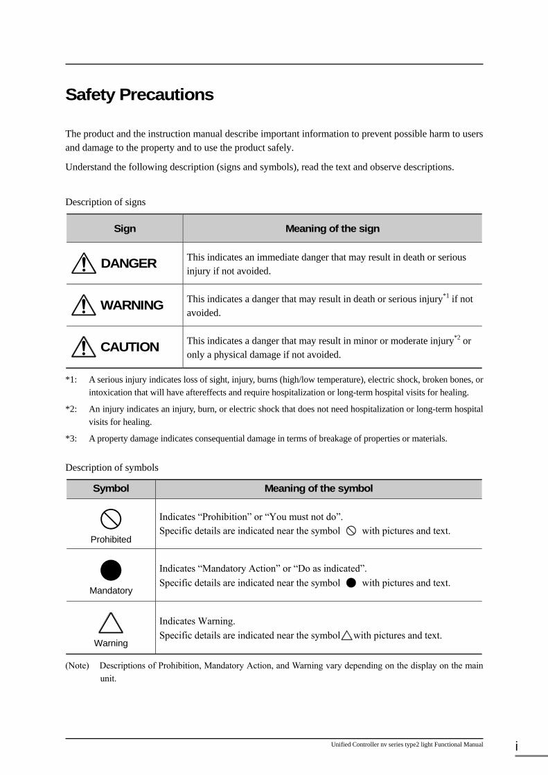
Description of signs
Sign Meaning of the sign
DANGER This indicates an immediate danger that may result in death or serious injury if not avoided.
WARNING This indicates a danger that may result in death or serious injury*1 if not avoided.
CAUTION This indicates a danger that may result in minor or moderate injury*2 or only a physical damage if not avoided.
*1: A serious injury indicates loss of sight, injury, burns (high/low temperature), electric shock, broken bones, or intoxication that will have aftereffects and require hospitalization or long-term hospital visits for healing.
*2: An injury indicates an injury, burn, or electric shock that does not need hospitalization or long-term hospital visits for healing.
*3: A property damage indicates consequential damage in terms of breakage of properties or materials.
Description of symbols
Symbol Meaning of the symbol
Prohibited
Indicates “Prohibition” or “You must not do”. Specific details are indicated near the symbol with pictures and text.
Mandatory
Indicates “Mandatory Action” or “Do as indicated”. Specific details are indicated near the symbol with pictures and text.
Warning
Indicates Warning. Specific details are indicated near the symbol with pictures and text.
(Note) Descriptions of Prohibition, Mandatory Action, and Warning vary depending on the display on the main unit.

6F8C1576 ii
1. Safety Precautions in Installation
WARNING
Ground the device.
Otherwise, it may cause an electric shock or fire.
CAUTION
Do not install, store, or use it in the following environments. ・ A place with a lot of dust ・ A place with corrosive gases (SO2, H2S)
ore flammable gases ・ A place with vibrations/impacts beyond a
permissible value. ・ A place that may have condensation due to
a rapid change of temperature. ・ Low/High temperature beyond installation
conditions ・ High humidity beyond installation
conditions ・ A place with direct sunlight ・ A place near devices that produce a strong
radio wave or magnetic field These may cause an accident.
Install it at a place facilitating easy maintenance/inspection.
Otherwise, it may cause an accident.
Do not block the vent hall and intake/outlet port.
Otherwise, it may cause a fire or failure.
Follow the installation conditions/method described in this manual regarding the installation of the system and wiring. Otherwise, it may cause a drop, fire, failure or malfunction.
Do not install/store relay output modules under the following conditions.
・ A place with silicon gas ・ A place using silicon products Otherwise, it may cause bad contact point.
Do not insert any foreign bodies, such as electric wire scraps, into the module/unite. Otherwise, it may cause a fire, failure, or malfunction.
Install Power modules, Controller modules, System bus modules, SBIF adaptor modules in the base unit. Otherwise, it may cause electric shock, injury, or failure. Do not use them as a single unit, and do not apply them to other applications.
Install TC-net I/O module to the base unit for nv series. Otherwise, it may case electric shock, injury, or failure. Do not use them as a single unit, and do not apply them to other applications.
Mount/dismount modules, base unit, terminal blocks only when the power is off. Otherwise, it may case electric shock, injury, or failure.
Use screws and confirm the firm connection of connectors and cables and the firm fitting of modules to base unit to hear a click sound when pushed and connected. Unsuccessful screwing may cause a failure or malfunction due to vibration.
Do not touch the card parts, contacts, connectors, or soldered surface. Ends of the lead wire of the parts may cause an injury, or electrostatic breakdown of the ICs or LSIs may occur, resulting in failure.
Ground
Prohibited
Mandatory
Prohibited
Prohibited
Mandatory
Prohibited
Mandatory
Mandatory
Mandatory
Mandatory
No touch

Unified Controller nv series type2 light Functional Manual iii
2. Safety Precautions in Wiring
WARNING
Perform wiring only when the power is off. Otherwise, it may case electric shock or failure.
For module wiring, use a crimp terminal with sheath or tape coating. Otherwise, it may cause electric shock due to exposed conductive part.
Ensure the installation of terminal cover on the terminal block. Exposure of conductive part may cause electric shock.
CAUTION
Connect external power within a rated value. Otherwise it may causes explosion or fire.
Wiring work must be done by worker with product knowledge. Otherwise, it may cause a fire, electric shock, or failure due to wrong wiring.
Install the fuses appropriate for current capacity to external circuit of a relay output module for protection against overload. Otherwise it may cause accident/machine damage due to load short circuit.
The battery is attached to the package. Before using type2 light, install the battery to the main unit. At shipping, the battery for type2 light is attached to the package. Just before using type2 light, install the battery.
Construct the emergency stop circuit and interlock circuit outside the nv series type2 light. Otherwise, it may cause an injury accident or damage to the machine if failure or malfunction occurs in the nv series type2 light.
Mandatory
Mandatory
Mandatory
Mandatory
Mandatory
Mandatory
Mandatory
Mandatory

6F8C1576 iv
3. Safety Precautions in Daily Use
WARNING
Do not modify, repair, disassemble, or adjust the device, module, or board. It may cause an electric shock, fire, injury, or failure. Upon faulty operation or failure, contact the nearest Toshiba's branch office or service offices.
Before using, check that the power capacity, frequency, voltage, and regulation comply with the device specifications. If not, it may cause damage of the device, or fire due to overheat, as well as not obtaining the original performance of the device.
When the ambient or internal temperature of the device rises abnormally or failure occurs in the device, stop using the device. Using it as it is may cause fire due to overheat. Turn off the power, and contact the nearest Toshiba's branch office or service offices.
Do not touch the terminals of the module and unit during energization. It may cause an electric shock. The power supply module is for the nv series only. Do not use it alone for any other purposes.
CAUTION
When performing program changes during operation, forced output, run, or halt operations, ensure safety. Wrong operations or failure to ensure safety may cause an accident or damage to the machine.
When there is any smoke or strange odor, turn off the power. Otherwise, it may cause a fire or electric shock. Contact the nearest Toshiba's branch office or service offices.
Do not forcefully bend, pull, or twist the power cord and cables. It may cause breaks or heating.
Do not insert any metal into the gaps of the device main body. It may cause fire.
Check the contact life of relay with contact used for relay output before use. After the contact life, abnormal output occurs for the relay due to bad contact, causing accident/machine damage. Relay with contact has a specific life due to contact abrasion. Replace it with a new one when the life may expired.
No touch Mandatory
Prohibited Prohibited
Mandatory
Mandatory
Mandatory
Prohibited
Prohibited

Unified Controller nv series type2 light Functional Manual v
Install the battery before use. Operation of RAM without battery may cause accident/machine damage due to loss data and program in memory and consequence malfunction. Replace batteries according to the recommended battery replacement period.
Turn on the power in the following order:
Turn on the external power for the I/O module and the external power for the load. → Turn on the power of type2 light controller.
If this order is not followed, it may cause an accident or damage to the machine due to malfunction.
For system safety, turn off the load power before the power of the nv series type2 light. If this order is not followed, it may cause an accident or damage to the machine. Share the external power supply for the I/O module with the load power supply whenever possible. If this is not possible, construct the system so that the external power supply and load power supply are turned off simultaneously.
Mandatory Mandatory
Mandatory

6F8C1576 vi
4. Safety Precautions in Maintenance and Inspection
WARNING
When installing or removing the module, unit, terminal block, or wiring cable, make sure that the external power supply is off. Otherwise, there will be live electric poles on the back of the external terminal block of the module, causing an electric shock.
Do not connect the battery in reverse, charge, disassemble, overheat it, throw it into fire, or short-circuit it. It may cause an explosion or fire.
When replacing the power fuse or alarm fuse of the device, turn off the power of the device. Otherwise, it may cause an electric shock or fire.
Replace fuses or batteries with specified items. Using anything other than specified may cause a fire or failure.
Be extremely careful when measuring the power supply voltage at the power terminal part of the module during an inspection. Otherwise, it may cause an electric shock.
CAUTION
Replace the batteries for PUM21 each 5 years when the annual average temperature is 30C or below, or for each 2 years when the annual average temperature is 30C or over. It may vary according to applications, but battery exhaustion may cause the loss of data or program stored on PUM21 to accidents or machine damage due to operational mistake.
Mandatory
Prohibited
Mandatory
Mandatory
Mandatory
Mandatory

Unified Controller nv series type2 light Functional Manual vii
5. Safety Precautions in Disposal
WARNING
Do not throw the lithium battery into a fire. The battery may explode.
CAUTION
When disposing of the lithium battery, follow the ordinances or rules of the local government. Otherwise, it may cause environmental damage.
Dispose of the unit and module of the nv series type2 light as industrial waste. Otherwise, it may cause environmental damage.
Prohibited
Mandatory Mandatory

6F8C1576 viii
6. Checking the Warning Label on the Main Body
Check that warning label is attached on the main body.
If the label is missing or hard to read due to stain, contact the nearest Toshiba office or agent.
[Warning symbols on the nv series type2 light main body]
This symbol is a warning symbol for dangerous parts. It is attached on places where there is a risk of an electric shock or a risk of damage to the main body due to wrong wiring.
Note the following where this symbol is present.
● Touching the power input terminal of the power supply module while the power is on causes an electric shock and is very dangerous. Do not touch the power input terminal.
● For safety, turn off the power before wiring or performing maintenance and inspection.
● Wire the power input terminal correctly, and avoid applying any voltage exceeding the specified voltage range. It may cause failure or damage.
● Perform connector connection of the nV-Tool port after turning off the power of the nV-Tool (such as the PC).
Turn on the power of the nV-Tool after connection.
Be careful not to short-circuit the connector pins with the connector cover.
[Warning stickers]
The warning sticker as shown in the left figure is attached to the power terminal of the nv series type2 light. Remove the sticker from the mount, and attach it on the main body of the nv series type2 light main body, or on a location near the nv series type2 light where it can be seen easily. There are stickers in both Japanese and English. Use the one that suits your need. When wiring, remove the sticker mount. If the sticker is damaged, contact your distributor.

Unified Controller nv series type2 light Functional Manual ix
Use Regulation
This product is not developed or manufactured for the system including the equipment directly related to human life (Note 1). Do not use the product for that purpose.
When using this product to the system that is related to the safety of human and seriously affects the maintenance of public function (Note 2), contact our sales section as the necessary special
consideration (Note 3) is required for the system operation, its maintenance and management.
(Note 1) The equipment directly related to human life means the following:
Medical equipment such as life sustaining equipment and equipment for operation.
(Note 2) The system that is related to the safety of human and seriously affects the maintenance of public function means the following:
Main equipment control system for nuclear power plant, safety protection system of nuclear facility, other system important for safety.
Operation control system of mass transportation system and aviation control system.
(Note 3) Special consideration means the sufficient consultation with our engineers to establish safe system (fool proof design, fail safe design, redundancy design).
Disclaimer
Toshiba Corporation shall not be liable for the damage due to earth quake, lightning, wind and flood damage, fire for which Toshiba is not responsible, conduct of third party, other accident, customer’s willful, negligence, erroneous use and other use under abnormal condition.
Toshiba Corporation shall not be liable for the incidental damage (loss of business profit, suspension of business, change and deletion of the memorized contents) arising from use of non use of this product.
Toshiba Corporation shall not be liable for the damage arising from the negligence to observe the instruction described in the instruction manual.
Toshiba Corporation shall not be liable for the damage arising from the malfunction due to the connection with other equipment.
Toshiba Corporation shall not be liable for the damage arising from the malfunction due to the combination with application program made by customer.

6F8C1576 x
Precautions on Usage
● Installation ・ Use your cellular phone or PHS one meter or more away from the product main unit in operation, various
transmission cables, and I/O cable. Otherwise, the system may malfunction. ・ When connecting the connectors and cables or installing the module to the base unit, secure them with screws
tightly. Insufficient tightening may cause failure or malfunction due to vibrations.
・ Do not drop or strike devices and modules and do not give the devices and modules any strong shocks. Otherwise, it may cause failure.
● Power wiring ・ Keep the cables from other lines as much as possible. Especially, keep them away 200mm or more from
power lines. ・ The terminal screw size is M3.5. As applicable crimp contacts, use the one for 3.5M screws whose width is
7mm or less. ・ Do not connect anything to the NC part.
● Use of sample programs ・ Use the sample programs described in the operation manual after performing an operation check. Make sure to
perform an operation check before actual operation to avoid an accident due to malfunction. ● Battery replacement
・ Battery replacement can be done while the unit is energized or not energized. When replacing the battery while the unit is not energized, complete the replacement within 3 minutes. If the unit is left without a battery for a long time, the content of the RAM memory may be lost.
・ The Battery Normal LED (BAT) may illuminate during battery replacement. This is not an error. If the voltage decreases with the battery installed, the state will be detected normally and the LED goes off.
・ The battery voltage is not compatible with manganese batteries, or alkaline batteries. Do not mix them. ・ Do not use a battery when 3 years or more have passed since the production date.
● Maintenance ・ Place a module removed from the unit on a conductive mat or conductive bag (used for a backup board) on a
grounded table. Otherwise, parts may be damaged due to static electricity.
・ Before touching the device or module, touch a grounded metal to discharge the static electricity of your body. Otherwise, it may cause malfunction or failure due to static electricity.
・ Wipe off stain on the device or module with a soft cloth. For severe stain, use a wet cloth wrung tightly. Leaving them stained may cause wrong decision or operational mistake.
・ Do not use benzene or thinner to remove stain on device or module. It may cause deformation or discoloration of the device panel or module.
・ To keep the system normal and avoid unnecessary troubles, perform daily inspections, regular inspections, and cleaning.
Unified Controller nv series type2 light Functional Manual xi
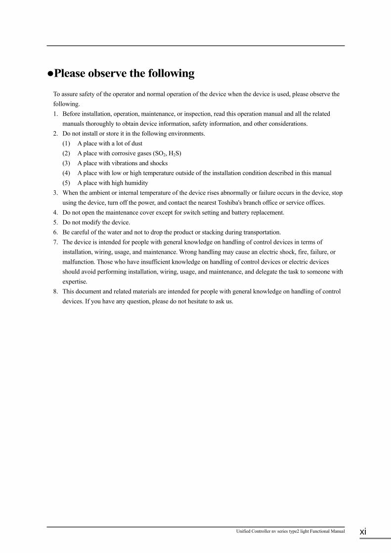
●Please observe the following
To assure safety of the operator and normal operation of the device when the device is used, please observe the following. 1. Before installation, operation, maintenance, or inspection, read this operation manual and all the related
manuals thoroughly to obtain device information, safety information, and other considerations. 2. Do not install or store it in the following environments.
(1) A place with a lot of dust (2) A place with corrosive gases (SO2, H2S) (3) A place with vibrations and shocks (4) A place with low or high temperature outside of the installation condition described in this manual (5) A place with high humidity
3. When the ambient or internal temperature of the device rises abnormally or failure occurs in the device, stop using the device, turn off the power, and contact the nearest Toshiba's branch office or service offices.
4. Do not open the maintenance cover except for switch setting and battery replacement. 5. Do not modify the device. 6. Be careful of the water and not to drop the product or stacking during transportation. 7. The device is intended for people with general knowledge on handling of control devices in terms of
installation, wiring, usage, and maintenance. Wrong handling may cause an electric shock, fire, failure, or malfunction. Those who have insufficient knowledge on handling of control devices or electric devices should avoid performing installation, wiring, usage, and maintenance, and delegate the task to someone with expertise.
8. This document and related materials are intended for people with general knowledge on handling of control devices. If you have any question, please do not hesitate to ask us.

6F8C1576 xii
The Unified Controller nv series is a new-style integrated controller that can be applied for power control in
addition to conventional electricity control and instrumentation control, a DCS model controller that mainly
executes loop control of instrumentation for mid-/large size system. This document describes mainly the following
contents related to the functions of the unified controller nv series type2 light.
・ Configuration of controller
This chapter describes system configuration , controller unit configuration, and I/O configuration.
・ Control operation
This chapter describes the operation mode of the controller unit, memory manage, etc.
・ Program
This chapter describes the types and operation of programs, execution control of task, and program error
monitoring, etc.
・ Variables
This chapter explains the variables handled by the controller unit, initialization, etc.
・ Input and Output
This chapter describes the input and output of the controller and I/O fallback.
・ nV-Tool support functions
This chapter describes the functions operated from nV-Tool connected to the type2 controller such as module
parameters, monitoring, and maintenance.
・ Standard input/output
This chapter describes the types of tag variables and their standard input/output.
・ RAS function
This chapter describes the RAS functions of the controller such as diagnosis function and log information.
Also refer to the following related descriptions other than this document.
・ Unified Controller nv series type2 light Controller Unit Instruction Manual 6F8C1575
・ High speed serial I/O system TC-net I/O Instruction Manual 6F8C1240
・ Industrial Instrumentation TC-net I/O System Instruction Manual 6F8C1381
・ Unified Controller nv series/Integrated Controller V series Programming Instructions 6F8C1226
・ Unified Controller nv series/Integrated Controller V series
Engineering Tool 4 -Basic-Instructions 6F8C1290
Introduction

Unified Controller nv series type2 light Functional Manual xiii
●The Rules on Notation
This document explains following symbols for the rules on notation for better understanding.
◆Important: Describes the matters that need special attention for appropriate product handling.
Note: Describes the matters to be observed for appropriate product handling.
Remark: Describes the supplementary matters to the described contents.

6F8C1576 xiv
Chapter 1
Configuration of Controller
…1
1.1 System Configuration ·················································· 2
1.2 Controller Unit Configuration ········································· 4
1.2.1 Single system configuration ······································· 4
1.2.2 Duplex system configuration ······································ 5
1.2.3 Module configuration ··············································· 6
1.3 I/O Configuration ······················································· 7
1.3.1 Connection of TC-net I/O series ·································· 7
1.3.2 Connection of Intelligent serial I/O series ······················· 8
1.4 Explanation of module parts ··········································· 9
1.4.1 Controller module (PUM21) ······································ 9
1.4.2 Controller status/Communication circuit board status LED ·· 10
1.4.3 Operation mode key switch ······································· 11
1.4.4 Mode setting switch ··············································· 12
1.4.5 Ethernet IP address setting switch ······························· 12
1.4.6 SBIF adaptor (SBM21) ·········································· 13
Chapter 2
Operation of Controller
…14
2.1 Basic Operation Flow ················································ 16
2.2 System Initialization Processing ···································· 17
2.3 Operation Mode Processing ········································· 19
2.3.1 Transition condition of operation mode ························· 19
2.3.2 Types and function of operation mode in single operation ··· 19
2.3.3 Operation mode and function in duplex operation ············· 20
2.4 Scan Processing ······················································· 23
2.4.1 Scan processing ···················································· 23
2.4.2 Scan synchronization processing ································· 24
2.5 Duplex Operation ····················································· 25
2.5.1 Power on start-up ·················································· 25
2.5.2 Power recovery operation ········································· 25
2.5.3 Target system monitoring ········································· 25
2.5.4 I/O status monitoring ·············································· 25
2.5.5 Network monitoring ··············································· 26
2.5.6 Download operation ··············································· 26
2.6 Causes of Duplex Switching ········································ 27
2.6.1 Forced switching ··················································· 27
2.6.2 Major failure of the controller ···································· 27
2.6.3 All station error of I/O ············································· 27
2.6.4 Major failure of Ethernet ·········································· 27
Unified Controller nv series type2 light Functional Manual xv
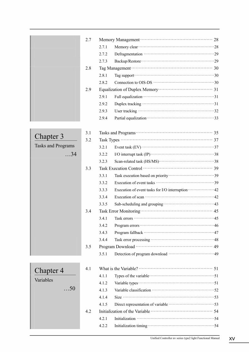
2.7 Memory Management ················································ 28
2.7.1 Memory clear ······················································· 28
2.7.2 Defragmentation ··················································· 29
2.7.3 Backup/Restore ····················································· 29
2.8 Tag Management ······················································ 30
2.8.1 Tag support·························································· 30
2.8.2 Connection to OIS-DS ············································ 30
2.9 Equalization of Duplex Memory ···································· 31
2.9.1 Full equalization ···················································· 31
2.9.2 Duplex tracking ···················································· 31
2.9.3 User tracking ······················································· 32
2.9.4 Partial equalization ················································· 33
Chapter 3
Tasks and Programs
…34
3.1 Tasks and Programs ··················································· 35
3.2 Task Types ····························································· 37
3.2.1 Event task (EV) ···················································· 37
3.2.2 I/O interrupt task (IP) ·············································· 38
3.2.3 Scan-related task (HS/MS)········································ 38
3.3 Task Execution Control ·············································· 39
3.3.1 Task execution based on priority ································· 39
3.3.2 Execution of event tasks ·········································· 39
3.3.3 Execution of event tasks for I/O interruption ··················· 42
3.3.4 Execution of scan ·················································· 42
3.3.5 Sub-scheduling and grouping ····································· 43
3.4 Task Error Monitoring ················································ 45
3.4.1 Task errors ·························································· 45
3.4.2 Program errors ······················································ 46
3.4.3 Program fallback ··················································· 47
3.4.4 Task error processing ·············································· 48
3.5 Program Download ··················································· 49
3.5.1 Detection of program download ································· 49
Chapter 4
Variables
…50
4.1 What is the Variable? ················································· 51
4.1.1 Types of the variable ··············································· 51
4.1.2 Variable types ······················································· 51
4.1.3 Variable classification ············································· 52
4.1.4 Size ·································································· 53
4.1.5 Direct representation of variable ································· 53
4.2 Initialization of the Variable ········································· 54
4.2.1 Initialization ························································ 54
4.2.2 Initialization timing ················································ 54

6F8C1576 xvi
4.3 Tag Variable ···························································· 55
4.3.1 Tag variable reference method ··································· 55
4.4 System Variable (ZW) ················································ 56
4.5 Inter-controller Transmission (MW, AW)·························· 56
Chapter 5
Input/Output
…57
5.1 I/O Processing ························································· 58
5.1.1 Batch I/O ···························································· 58
5.1.2 IQ register and I/O connection ··································· 58
5.1.3 I/O module and IQ register allocation ··························· 59
5.1.4 Direct I/O ··························································· 60
5.1.5 I/O interruption ····················································· 61
5.2 I/O Fallback ···························································· 62
5.2.1 I/O fallback ························································· 62
5.2.2 I/O fallback procedure ············································· 63
5.2.3 I/O recovery procedure ············································ 63
5.3 I/O Error Monitoring ················································· 64
5.4 Continuation and Suspension of I/O Module Operation ········· 64
Chapter 6
Standard I/O
…65
6.1 Tag Variables and Standard I/O Processing ······················· 66
6.2 Types of Tag Variables ··············································· 67
6.3 Four Functions of Standard I/O ····································· 68
6.4 Details of Standard I/O Processing ································· 70
6.5 Sequence Tag ·························································· 79
6.6 Process Alarm ························································· 79
Chapter 7
nV-Tool Support Function
…81
7.1 Module Parameters ··················································· 82
7.1.1 Controller operation specification ······························· 82
7.1.2 Task execution specification ······································ 83
7.1.3 Duplex information and tracking ································ 84
7.1.4 Status change indication ··········································· 85
7.1.5 Other and Ethernet ················································· 86
7.1.6 I/O loop ······························································ 87
7.1.7 I/O node ····························································· 88
7.2 Execution Status Monitor ············································ 89
7.2.1 Task run time measurement ······································· 89
7.2.2 Program monitor ··················································· 91
7.2.3 Data monitors ······················································· 91
7.3 Online Maintenance ·················································· 92
7.3.1 I/O live insertion/removal ········································· 92

Unified Controller nv series type2 light Functional Manual xvii
7.3.2 Scan cycle ··························································· 92
7.3.3 Program download ················································· 92
7.3.4 Instruction word swap ············································· 93
7.3.5 Contact and coil forces ············································ 93 Chapter 8
RAS Function
…94
8.1 Hardware Diagnosis ·················································· 96
8.1.1 Power-on diagnosis ················································ 96
8.1.2 Regular diagnosis ·················································· 96
8.1.3 Runtime diagnosis ················································· 96
8.2 Software Diagnosis ··················································· 97
8.2.1 Program structure monitoring ···································· 97
8.2.2 Execution time monitoring········································ 97
8.3 System Tags ···························································· 98
8.3.1 Error information ··················································· 98
8.3.2 System information ················································ 98
8.4 System Logs ··························································· 99
8.4.1 Error log ····························································· 99
8.4.2 Event log ···························································· 99
8.4.3 Transmission log ··················································· 99
8.4.4 Interruption log ····················································· 99
8.4.5 Notes on system logs ············································ 100
8.5 System logs of transmission part··································· 100
8.6 Troubleshooting ······················································ 101
8.6.1 Occurrence of errors ············································· 101
8.6.2 LED error indicators on the front panel ······················· 101
8.7 List of Diagnosis Items ·············································· 102 Appendix A
Function Specification and System Variable (ZW)
…121
Appendix B
Precautions on Use and Restrictions
…136
A.1 Function Specifications ············································· 122
A.2 List of System Variables (ZW) ····································· 125
B.1 Notes on Use and Modifications ··································· 137
B.2 Application Registration in Duplexing ···························· 139
B.2.1 Identification of duplexing ······································ 139
B.2.2 Parameter changes (for future use) ···························· 139
B.2.3 Event tasks in switching ········································· 139
B.2.4 Identification of switching ······································ 140
B.3 Restrictions on Process Tag Output ······························· 141

6F8C1576 xviii
Appendix C
List of Process Tags
…144
C.1 PV (Indicator) ························································ 145
C.1.1 Parameters ························································ 145
C.1.2 Data ································································ 153
C.2 LP (Controller) ······················································· 157
C.2.1 Parameters ························································ 157
C.2.2 Data ································································ 162
C.3 PB (Pushbutton) ······················································ 166
C.3.1 Parameters ························································ 166
C.3.2 Data ································································ 170
C.4 TC (Timer/Counter) ················································· 173
C.4.1 Parameters ························································ 173
C.4.2 Data ································································ 175
C.5 DB (Data Block) ····················································· 177
C.5.1 Parameters ························································ 177
C.6 SQ (Sequence Operation Equipment) ····························· 178
C.6.1 Parameters ························································ 178
C.6.2 Data ································································ 179
Appendix D
Run-Time Calculation
…180
D.1 Scan Cycle Calculation·············································· 181
D.2 Operable Application at the Maximum Speed ··················· 182
Appendix E
Migration method from L2PU22 system
…183
E.1 Judgment for Migration ············································· 184
E.2 Ready for Migration ················································· 185
E.2.1 Copy of the system ··············································· 185
E.2.2 Deletion of the unnecessary element of the L2PU22 station ·· 185
E.2.3 Export of L2PU22 station ······································· 185
E.2.4 Export of the tag ·················································· 187
E.2.5 Export of the variable value ···································· 187
E.3 Operation for Migration ············································· 189
E.3.1 Entry of the hardware constitution ····························· 189
E.3.2 Entry of the standard variable ·································· 189
E.3.3 Import of the tag ·················································· 189
E.3.4 Import of the variable value ···································· 189
E.3.5 Batch compile ···················································· 189
E.4 Detailed Contents of Operation ···································· 190
E.4.1 Editing of the station export file ································ 190
E.4.2 Editing of the tag export file ···································· 193
E.4.3 Entry of the module parameter ································· 194

1
Chapter 1 Configuration of Controller The Unified Controller nv series type2 light controller (herein after called the “type2 light controller”) is a controller with functions to be used in mid- and mini-size instrumentation systems.
It can constitute an instrumentation system by connecting a type2 light controller to the Operator Station OIS-DS for Toshiba CIE Integrated Control System CIEMAC-DS via network, or to the TC-net I/O via the TC-net I/O loop.
1.1 System Configuration ················································· 2 1.2 Controller Unit Configuration ······································ 4
1.2.1 Single system configuration ································· 4 1.2.2 Duplex system configuration ································ 5 1.2.3 Module configuration ········································ 6
1.3 I/O Configuration ······················································ 7 1.3.1 Connection of TC-net I/O series ···························· 7 1.3.2 Connection of Intelligent serial I/O series ················· 8
1.4 Explanations of module parts ······································· 9 1.4.1 Controller module (PUM21) ································ 9 1.4.2 Controller status/Communication circuit board
status LED on front panel ·································· 10 1.4.3 Operation mode key switch ································ 11 1.4.4 Mode setting switch ········································· 12 1.4.5 Ethernet IP address setting switch ························· 12 1.4.6 SBIF adaptor (SBM21) ····································· 13

Chapter 1 Configuration of Controller
6F8C1576 2
1.1 System Configuration
Figure 1-1 shows example of the configuration of type2 light Controller system.
Ethernet
SB
IF
SB
IF I/O
SB
IF
SB
IF I/O
TB
SB
IF
SB
IF I/O
SB
IF
SB
IF I/O
TB
⑧Intelligent serial I/O
②Engineering tool
①OIS-DS
TB :Broadcast terminal stand SBIF :Serial bus I/F module I/O(SBIF connection) :Intelligent I/O module RP :Electric / light converter SIO(SA9**) :TC-netI/O loop I/F module I/O(SIO connection) :TC-netI/O module SH-I/O :TC-netI/O module for HART FL :TC-netI/O module for FL-net MD :TC-netI/O module for Modbus PA :TC-netI/O module for Profibus
SIO
I/O
I/O
SH
-I/O
SH
-I/O
SIO
I/O
SIO
FL
SIO
MD
RP
PA
⑥TC-netI/O
⑤TC-netI/O Loop
HART
Generic
I/O
FL-net
Generic I/O
MODBUS
Generic I/O
Profibus
④type2 light
⑦Serial I/O bus
③Control LAN
Figure 1-1 Configuration of type2 light controller system (example)
① OIS-DS
The OIS-DS, CIEMAC's standard HMI(human interface), supports the nv series type2 light
controller (the standard software of the latest version is required).
② Engineering tool(thereafter, called as nV-Tool)
The unified controller nv series/integrated controller V series engineering tool 4 (nV-Tool)
supports the type2 light controller.
nV-Tool is used via the control LAN.
③ Control LAN
A control LAN is configured with duplex Ethernet (100M).
④ type2 light
Controller modules (PUM21) has built-in DS connection interface dedicated to OIS-DS
communications.

1.1 System Configuration
Unified Controller nv series type2 light Functional Manual 3
⑤ TC-net I/O loop
This is the network group to connect the type2 light controller module to TC-net I/O.
⑥ TC-net I/O (Note 1)
Interface modules (SA9**) and unified controller nv series I/O modules to connect TC-net
I/O module to TC-net I/O loop node via TC-net I/O loop.
⑦ Serial I/O bus
This is a bus to connect type2 light controller modules to intelligent serial I/O.
⑧ Intelligent serial I/O
This is the I/O module of previous model’s intelligent serial I/O series.
Note (Note 1) The type2 light controller supports only a single line of TC-net I/O loop.
For detail of I/O, see following manuals: ・High-speed serial I/O system TC-net I/O Instruction Manual (6F8C1240)
・Industrial Instrumentation TC-net I/O System Instruction Manual (6F8C1381)
Chapter 1 Configuration of Controller
6F8C1576 4
1.2 Controller Unit Configuration
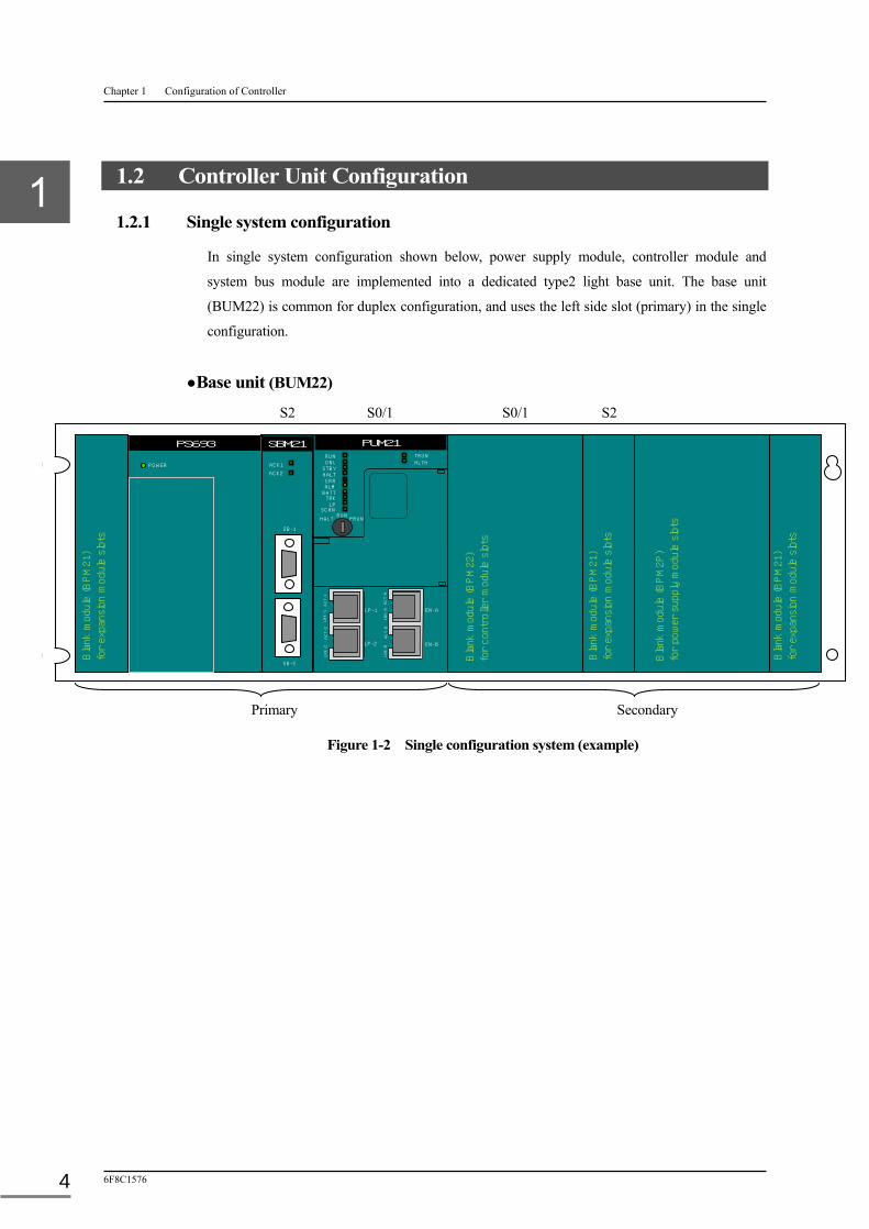
1.2.1 Single system configuration
In single system configuration shown below, power supply module, controller module and
system bus module are implemented into a dedicated type2 light base unit. The base unit
(BUM22) is common for duplex configuration, and uses the left side slot (primary) in the single
configuration.
●Base unit (BUM22)
Figure 1-2 Single configuration system (example)
ACK1
ACK2
SB-1
SB-2
SBM21
POWER
PS693
PUM21
RUN HALT PRUN
TRUN HLTH
RUN ONL
STBY HALT ERR ALM
BATT TRK
LP SCAN
EN-B
LP-1
LP-2
EN-A
AC
T-1
AC
T-A
AC
T-2
AC
T-B
LNK-1
LN
K-2
LNK-A
LN
K-B
Bla
nk m
odul
e (B
PM
2P)
fo
r po
wer
sup
ply
mod
ule
slot
s
Bla
nk m
odul
e (B
PM
21)
fo
r ex
pans
ion
mod
ule
slot
s Bla
nk m
odul
e (B
PM
22)
fo
r co
ntro
ller
mod
ule
slot
s
Bla
nk m
odul
e (B
PM
21)
fo
r ex
pans
ion
mod
ule
slot
s B
lank
mod
ule
(BPM
21)
fo
r ex
pans
ion
mod
ule
slot
s
Primary
S2 S0/1 S2 S0/1
Secondary

1.2 Controller Unit Configuration
Unified Controller nv series type2 light Functional Manual 5
1.2.2 Duplex system configuration
The duplex system is a standby redundant system with duplexed controller unit main body, and the operation system (the system executing control) is called online, and the standby system (system in the standby state) is called standby. When the operation system stops, the standby system automatically switches to the operation system. Also, when they are started up simultaneously, the system that starts up preferentially as online is called primary (left side), and the system that starts up as standby is called secondary (right side).
In the duplex system, TC-net I/O loop is connected to both the primary and secondary controller modules.
● Base unit (BUM22)
Figure 1-3 Duplex configuration system (example)
ACK1
ACK2
SB-1
SB-2
SBM21 ACK1
ACK2
SB-1
SB-2
SBM21
POWER
PS693
PUM21
RUN HALT PRUN
TRUN HLTH
RUN ONL
STBY HALT ERR ALM
BATT TRK
LP SCAN
EN-B
LP-1
LP-2
EN-A
AC
T-1
AC
T-A
AC
T-2
AC
T-B
LNK-1
LN
K-2
LNK-A
LN
K-B
PUM21
RUN HALT PRUN
TRUN HLTH
RUN ONL
STBY HALT ERR ALM
BATT TRK
LP SCAN
EN-B
LP-1
LP-2
EN-A
AC
T-1
AC
T-A
AC
T-2
AC
T-B
LNK-1
LN
K-2
LNK-A
LN
K-B
POWER
PS693
Bla
nk m
odul
e (B
PM
21)
fo
r ex
pans
ion
mod
ule
slot
s
Bla
nk m
odul
e (B
PM
21)
fo
r ex
pans
ion
mod
ule
slot
s
Primary
S2 S0/1 S2 S0/1
Secondary

Chapter 1 Configuration of Controller
6F8C1576 6
1.2.3 Module configuration
The potential combination of the modules that can be mounted on the base unit slot is shown
below.
Table 1-1 Module type
Base unit (BUM22) (Note 1)
Primary Secondary
S2 S0/1 S0/1 S2
PUM21 - ○ ○ ○ ○ -
SBM21 ○ - - - - ○
Note
(Note 1) The system operates as a single system when the type2 light controller module (PUM21) is mounted only on the primary side of the base unit for dual configuration (BUM22), but does not operate as a single system when PUM21 is mounted only on the secondary side.
1.3 I/O Configuration
Unified Controller nv series type2 light Functional Manual 7
1.3 I/O Configuration
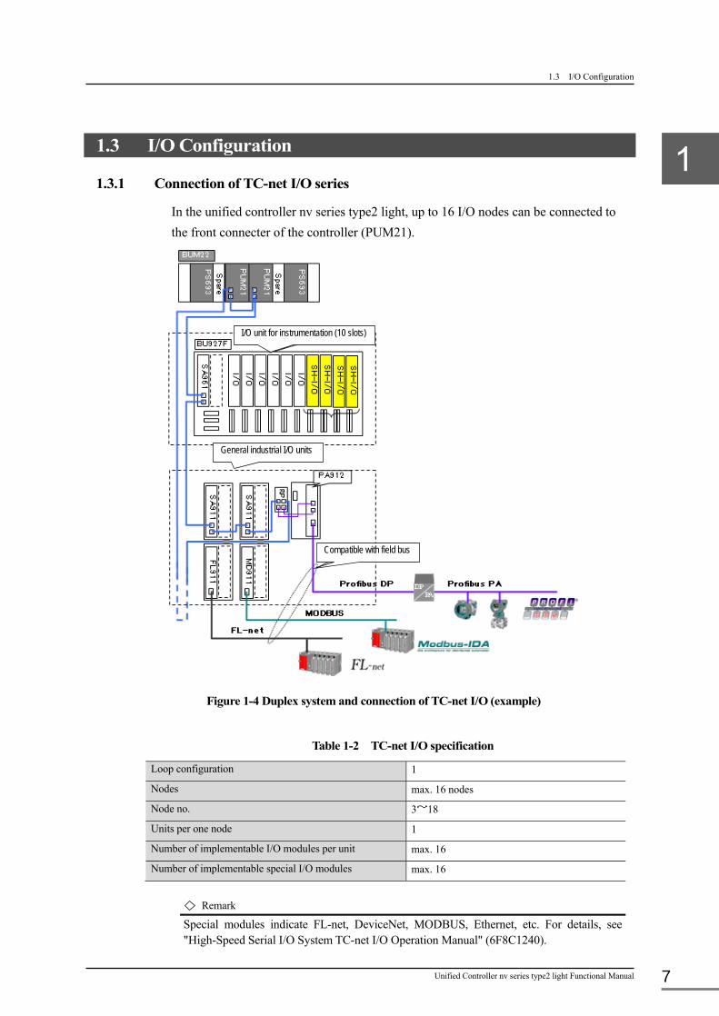
1.3.1 Connection of TC-net I/O series
In the unified controller nv series type2 light, up to 16 I/O nodes can be connected to
the front connecter of the controller (PUM21).
Figure 1-4 Duplex system and connection of TC-net I/O (example)
Table 1-2 TC-net I/O specification
Loop configuration 1
Nodes max. 16 nodes
Node no. 3~18
Units per one node 1
Number of implementable I/O modules per unit max. 16
Number of implementable special I/O modules max. 16
Remark
Special modules indicate FL-net, DeviceNet, MODBUS, Ethernet, etc. For details, see "High-Speed Serial I/O System TC-net I/O Operation Manual" (6F8C1240).
I/O unit for instrumentation (10 slots)
General industrial I/O units
Compatible with field bus
Chapter 1 Configuration of Controller
6F8C1576 8
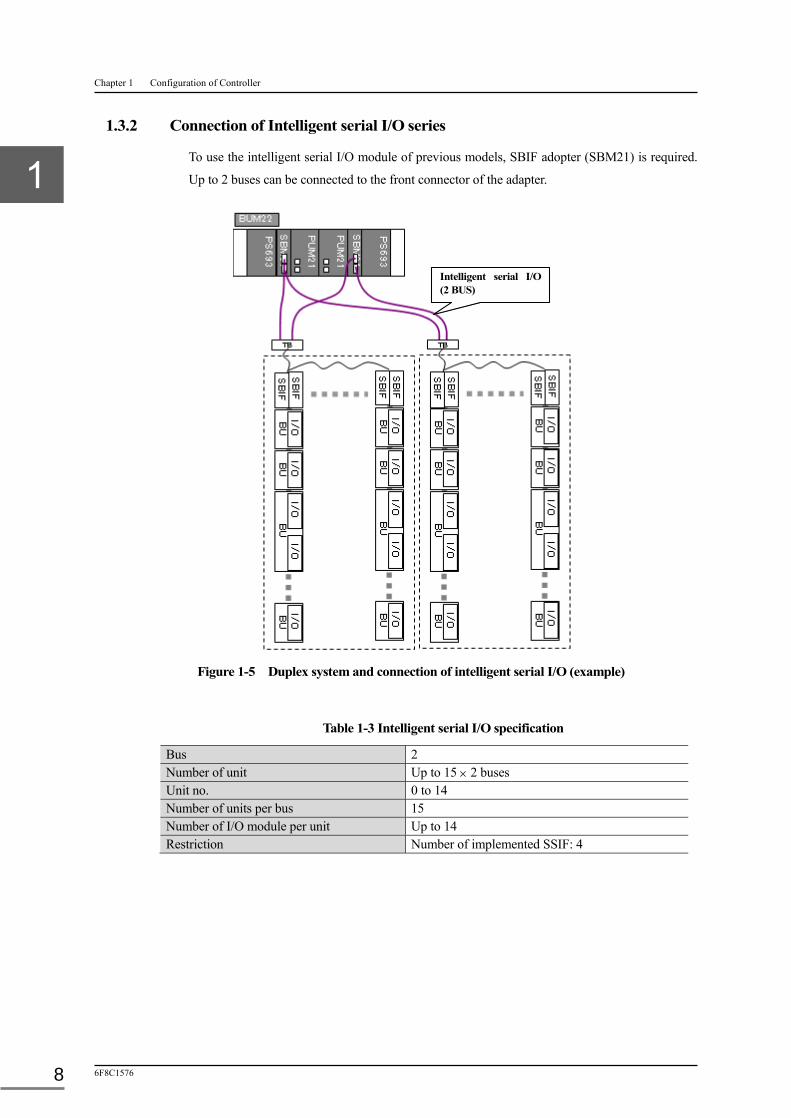
1.3.2 Connection of Intelligent serial I/O series
To use the intelligent serial I/O module of previous models, SBIF adopter (SBM21) is required.
Up to 2 buses can be connected to the front connector of the adapter.
Figure 1-5 Duplex system and connection of intelligent serial I/O (example)
Table 1-3 Intelligent serial I/O specification
Bus 2 Number of unit Up to 15 2 buses Unit no. 0 to 14 Number of units per bus 15 Number of I/O module per unit Up to 14 Restriction Number of implemented SSIF: 4
Intelligent serial I/O (2 BUS)

1.4 Explanations of module parts
Unified Controller nv series type2 light Functional Manual 9
1.4 Explanations of module parts
1.4.1 Controller module (PUM21)
The following diagram shows the outside drawing of a type2 light controller module (PUM21).
(With the maintenance cover opened)
Figure 1-6 Outside drawing of controller module
① Controller status LED
This displays the operation status of the controller and connection status of TC-net I/O.
② Communication circuit board status
This displays the operation status of the communication circuit board.
③ Operation mode key switch
A switch to manipulate the operation mode of the controller
④ IP address configuration switch (Normally hidden by the maintenance cover)
A rotary switch to configure Ethernet IP
⑤ Maintenance connector (Normally hidden by the maintenance cover)
A connector for the system used for software update, execution of test program and others
⑥ Built-in battery holder (Normally hidden by the maintenance cover)
A holder to store the battery for memory backup
⑦ Mode setting switch (Normally hidden by the maintenance cover)
A dip switch to select functions including memory clear
⑧ TC-net I/O connector
A connector to connect the controller and TC-net I/O
⑨ Ethernet connector for DS connection
A connector to connect the controller and control LAN
STN-H
STN-L
MODE
ON →
RUN ONL
STBY HALT
ERR ALM
BATT TRK LP
SCAN
TRUN HLTH
PUM21
RUN HALT PRUN
BATT
MAINT
LP-1
LP-2 EN-B
EN-A
AC
T-1
AC
T-A
AC
T-2
AC
T-B
LNK-1
LN
K-2
LNK-A
LN
K-B
Power supply bus connector
Connector for Power supply /System bus
/Tracking bus
①Controller status LED
⑦Mode setting switch ⑤Maintenance
connector
⑧TC-net I/O connector ⑨Ethernet connector for
DS connection
④IP address configuration switch
⑥Built-in battery holder
Back
Front
③Operation mode key switch
②Communication circuit board status
Chapter 1 Configuration of Controller
6F8C1576 10
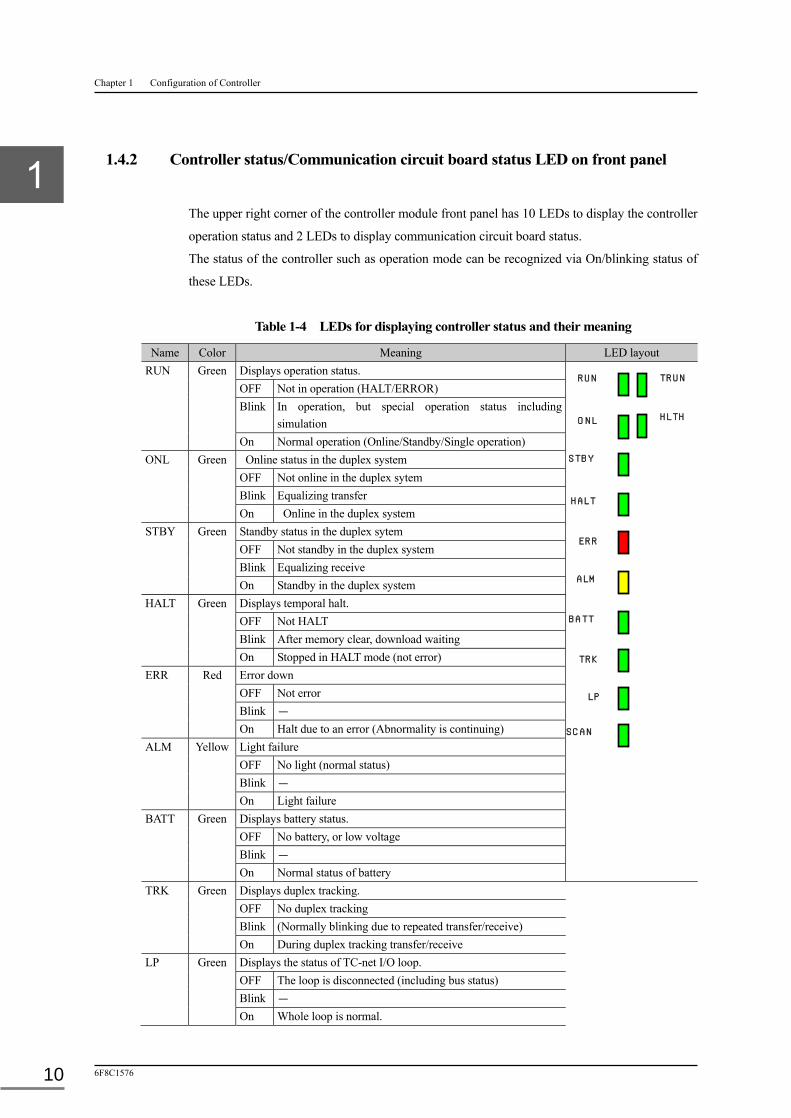
1.4.2 Controller status/Communication circuit board status LED on front panel
The upper right corner of the controller module front panel has 10 LEDs to display the controller
operation status and 2 LEDs to display communication circuit board status.
The status of the controller such as operation mode can be recognized via On/blinking status of
these LEDs.
Table 1-4 LEDs for displaying controller status and their meaning
Name Color Meaning LED layout RUN Green Displays operation status.
OFF Not in operation (HALT/ERROR) Blink In operation, but special operation status including
simulation On Normal operation (Online/Standby/Single operation) ONL Green Online status in the duplex system OFF Not online in the duplex sytem Blink Equalizing transfer On Online in the duplex system STBY Green Standby status in the duplex sytem OFF Not standby in the duplex system Blink Equalizing receive On Standby in the duplex system HALT Green Displays temporal halt. OFF Not HALT Blink After memory clear, download waiting On Stopped in HALT mode (not error) ERR Red Error down OFF Not error Blink - On Halt due to an error (Abnormality is continuing) ALM Yellow Light failure OFF No light (normal status) Blink - On Light failure BATT Green Displays battery status. OFF No battery, or low voltage Blink - On Normal status of battery TRK Green Displays duplex tracking. OFF No duplex tracking Blink (Normally blinking due to repeated transfer/receive) On During duplex tracking transfer/receive LP Green Displays the status of TC-net I/O loop. OFF The loop is disconnected (including bus status) Blink - On Whole loop is normal.
TRUN
HLTH
RUN
ONL
STBY
HALT
ERR
ALM
BATT
TRK
LP
SCAN

1.4 Explanations of module parts
Unified Controller nv series type2 light Functional Manual 11
SCAN Green Displays the status of TC-net I/O scan transfer. OFF I/O scan transfer is stopped. Blink - On Transferring I/O scan. TRUN Green Displays the status of communication function. OFF Communication is stopped. Blink - On In communication HLTH Green The status of communication circuit board (built-in) OFF Stopped due to abnormality on the communication circuit
board Blink - On The status of communication board is normal.
Remark
・As a general rule, Green on displays normal, while red on or yellow on display abnormal status. OFF displays no application. When, however, there is not any item to be displayed with Green ON, it indicates abnormality, regardless of items shown with Red ON or Yellow ON.
1.4.3 Operation mode key switch
The operation mode switch is used to switch the operation mode and operation state.
Table 1-5 Operation mode switch
Switch position Operation Operation mode SW layout
HALT ・Switching from the positions other than the HALT mode to HALT changes to the HALT mode.
・When the power is turned on in the HALT state, the system starts up in the HALT mode.
・Operation mode switching from the nV-Tool is not accepted.
RUN ・Switching from HALT to RUN changes to the RUN mode. ・It can be changed to the HALT mode by operation mode switching from the nV-Tool.
P-RUN ・The operation state is the same as RUN. Write of the entire program is prohibited.

Chapter 1 Configuration of Controller
6F8C1576 12
1.4.4 Mode setting switch
The dip switches can be used to select functions including memory clear. The dip switches are
behind the maintenance cover. Remove the cover to check the state or perform setting.
Table 1-6 DIP switch specification
Name Function Remark DIP switch layout DSW-1 Reserved for manufacturer Ensure to make it OFF.
DSW-2
DSW-3
DSW-4
DSW-5
DSW-6
DSW-7 Theses switches determine whether or not to perform memory clear at power-on.
Operation: Turn the key switch to HALT, turn on SW-7 and -8, and turn on the power again. When memory is cleared, HALT indicator flashes. Turn off SW-7 and -8 again, and turn on the power
DSW-8
1.4.5 Ethernet IP address setting switch
Switches that set Ethernet IP address.
Set least four digits of the IP address.
Table 1-7 Specification of Ethernet IP address setting switch
Name Contents Switch layout H Upper digits (0 to F) of least four digits of IP address that is
converted to hexadecimal.
L Lower digits (0 to F) of least four digits of IP address that is converted to hexadecimal.
Remark
・The 4th least digit of the IP address can be set with a decimal number 1 to 126. Zero and values of 127 or larger cannot be set.

1.4 Explanations of module parts
Unified Controller nv series type2 light Functional Manual 13
1.4.6 SBIF adaptor (SBM21)
The figure below shows outside drawing of a SBIF adaptor.
2 buses of intelligent serial I/O can be connected as the I/F function of external I/O.
This has a system bus connector to facilitate the access between controller modules and
intelligent serial I/O.
Figure 1-7 Outside drawing of a SBIF adaptor module
① Access status of serial I/O LED
Displays the status of the access between the controller to the intelligent serial I/O.
② Serial I/O bus connection connecter
This is a connecter to connect the controller and the intelligent serial I/O.
2 buses can be connected.
ACK1
ACK2
SBM21
SB-1
SB-2
Power/System bus connecter
Back
②Serial I/O bus
①Access status of serial
Front

14
Chapter 2 Operation of Controller This chapter describes the basic operation of the unified controller nv series type2 light controller
(hereafter called the “type2 light controller”) main unit.
2.1 Basic Operation Flow ························································· 16
2.2 System Initialization Processing ············································ 17
2.3 Operation Mode Processing·················································· 19
2.3.1 Transition condition of operation mode ··························· 19
2.3.2 Types and function of operation mode in single operation ····· 19
2.3.3 Operation mode and function in duplex operation ··············· 20
2.4 Scan Processing ································································· 23
2.4.1 Scan processing ······················································ 23
2.4.2 Scan synchronization processing ··································· 24
2.5 Duplex Operation ······························································ 25
2.5.1 Power on start-up ····················································· 25
2.5.2 Power recovery operation ··········································· 25
2.5.3 Target system monitoring ··········································· 25
2.5.4 I/O status monitoring ················································ 25
2.5.5 Network monitoring ················································· 26
2.5.6 Download operation ················································· 26
2.6 Causes of Duplex Switching ·················································· 27
Unified Controller nv series type2 light Functional Manual 15
2.6.1 Forced switching ····················································· 27
2.6.2 Major failure of the controller ······································ 27
2.6.3 All station error of I/O ··············································· 27
2.6.4 Major failure of Ethernet ············································ 27
2.7 Memory Management ························································ 28
2.7.1 Memory clear ························································· 28
2.7.2 Defragmentation ······················································ 29
2.7.3 Backup/Restore ······················································· 29
2.8 Tag Management ······························································· 30
2.8.1 Tag support ···························································· 30
2.8.2 Connection to OIS-DS ··············································· 30
2.9 Equalization of Duplex Memory ············································ 31
2.9.1 Full equalization ······················································ 31
2.9.2 Duplex tracking ······················································ 31
2.9.3 User tracking ·························································· 32
2.9.4 Partial equalization ··················································· 33

Chapter 2 Operation of Controller
6F8C1576 16
2.1 Basic Operation Flow
Figure 2-1 shows the basic operation flow of the controller main unit.
Figure 2-1 Basic operation flow
When turning on the power, the controller performs following processing:
① The controller executes the system initialization at first, and then operation mode processing
if no error occurs during initialization.
② In the operation mode processing, scan processing is executed if the conditions to run in the
RUN mode are established.
If the conditions to run in the RUN mode are not established, or any abnormality is detected,
the system status becomes the HALT (ERROR when abnormality is detected) mode and the
execution of scan processing is stopped.
③ Scan processing includes standard I/O processing that handles execution of user program,
conversion of I/O signals specific to instrumentation control, and filtering as well as the
batch I/O processing of I/O data.
④ The peripheral support processing writes/reads the information requested from nV-Tool and
OIS-DS, asynchronously with scan processing.
⑤ The self diagnosis processing performs regular hardware/software inspections. And it
performs particular diagnosis individually in each process.
HALT (ERROR) mode
電源投入
システム初期化処理
運転モード処理
Self-diagnosis
RUN mode
Scan processingInformation support
Power on
System initialization processing
Operation mode processing

2.2 System Initialization Processing
Unified Controller nv series type2 light Functional Manual 17
2.2 System Initialization Processing
When the power is turned on, the standard software in the nonvolatile memory is loaded and
execution starts.
The system initialization processing performs diagnosis of the storing status of program-related
information stored in the memory, and hardware diagnosis.
Figure 2-2 System initialization processing flow
① Self diagnosis of hardware and its initialization
The system ROM and RAM are checked, and the system is initialized.
When an error is detected during checking, error logs are registered and it transfers to the
error mode to halt. For details, see Chapter 8 RAS Function.
② Date and time of power ON/OFF registration
The last date and time when power was OFF is registered into the event log. Further, the
present date and time read out from calendar LSI is registered as the power ON date and time.
③ Memory erasure check
It is checked whether the memory content (programs and control data) is correctly backed up
by the battery. If memory erasure is detected, error log is registered and it transfers to the
download wait status to halt.
①
②
③
④
⑤
⑥
HW self-diagnosis and initialization
Power ON/OFF date entry
Memory erasure check
Battery check
User program check
Variables initialization

Chapter 2 Operation of Controller
6F8C1576 18
④ Battery check
Whether or not the back up battery for memory is installed is checked as well as its voltage.
If the back up battery is not installed, the message “No battery” is registered into the error log.
If the battery voltage is lower than the defined value, the message "Low voltage" is registered
into the error log.
⑤ Program check
The contents of program running on the memory are checked.
⑥ Variables initialization
Local and global variables and tag information are initialized. For details, see Chapter 4
Variables.
Remark
<Long interruption and short interruption>
The internal clock (RTC) measures the time between power-off and next power-on in seconds, and
computes the power suspension time. When the computed time exceeds the preset short interruption of
power, long interruption processing is conducted, or when the time is less than the preset value, short
interruption processing is carried out (short interruption is specified with nV-Tool.).
・During long interruption processing, the current output value is read back after the output status of the
output module is confirmed, and control restarts based on that value.
・During long interruption processing, M mode is set on the control loop for all indicator tags (#LP). The
control mode is, however, not changed when output is not for the output device of TC-net I/O modules or
intelligent I/O modules.
During short interruption processing, all output modules output the value immediately before interruption
again, and then control resumes.
・The EV0 task for long interruption, or the EV1 task for short interruption is executed once at the
beginning. These event tasks can be used when a specific processing in association with power
interruption time is required.

2.3 Operation Mode Processing
Unified Controller nv series type2 light Functional Manual 19
2.3 Operation Mode Processing
2.3.1 Transition condition of operation mode
To grasp the operation of the entire controller, the operation is classified into operation modes to
control the operation from power on to power down.
The transition of operation modes can be checked with the event log. Also, the operation mode
state can be checked on the controller state display LED on the front panel of the controller
module.
2.3.2 Types and function of operation mode in single operation
Self-diagnosis result, program execution status, I/O status, operation mode switch manipulation,
operation mode request from nV-Tool are determined.
・INZ mode indicates the initialization processing.
・RUN mode indicates the ordinary online operation.
・HALT mode indicates the halt status.
・DL-WAIT mode indicates the system shutdown wait status.
・ERROR mode indicates the abnormal stop status caused by a major error.
・S-HOLD mode indicates the transitional status during which demotion is performed to move
to HALT mode.
・O-HOLD mode indicates the transitional status during which promotion is performed to
move to RUN mode.
Figure 2-3 Operation mode processing in single operation
ERR (Halt due to error)
S-HOLD (I/0 demotion)
INZ (Initialization)
Error reset KEY: HALT
DL
Error reset Not DL
Memory clear
Normal startup Run command
RUN command
INZ HALT DL-WAIT S-HOLD
O-HOLD RUN
HALT (Stop)
DL-WAIT (DL waiting)
O-HOLD (Normal startup
promotion)
HALT command
S-HOLD (Forced shutdown
demotion)
RUN (Online operation)

Chapter 2 Operation of Controller
6F8C1576 20
Table 2-1 Types and function of Operation mode transition in single operation
Mode Operation details Remark
INZ Initialization and self diagnosis of the controller are executed.
When the power is turned on, initialization and self diagnosis are performed. If successful, the mode automatically transits to the next operation mode.
HALT Forced stop state Operation stops in this mode when halt is requested during online operation, or the operation mode switch is turned to HALT during power-ON. (Note 1)
RUN Continuous execution of user programs and scan processing including batch I/O
Online operation is continued until halt is requested or a major error is detected.
ERROR Error stop state Operation stops in this mode when a major error is detected. (Note 2)
DL-WAIT Download wait status At the startup after memory clear, the controller waits for download in this mode. (Note 3)
O-HOLD Promotion processing of I/O is executed.
I/O processing is started to move to RUN mode.
S-HOLD Demotion processing of I/O is executed.
Input/output is stopped, and the system transits to HALT or ERROR.
Remark
(Note 1) To reset HALT, turn the operation mode switch from HALT to RUN, or select RUN from the nV-Tool.
(Note 2) To reset ERROR, turn the operation mode switch from HALT to RUN, or request an error reset from the nV-Tool.
(Note 3) When download is complete, turn the operation mode switch from HALT to RUN, or select RUN from the nV-Tool to automatically transit to R-WAIT.
2.3.3 Operation mode and function in duplex operation
Operation modes specific to duplex operation are listed below.
・Online operation (MAS-RUN) The online system operates in normal duplex mode. The operation can be switched to the standby system any time.
・Standby operation (SLV-RUN)
The standby system operates in normal duplex mode. The operation can be switched to the
online system any time.
・Single operation (ODD-RUN)
Only a single system operates.
In duplex operation, information in the online and standby systems are equalized at the startup.
The following two modes indicate the equalization operation:
・Equalization transmission (EQL-RUN) The online system transmits information for equalization to the standby system.
・Equalization receiving (RCV-H) The standby system receives information for equalization from the online system.
2.3 Operation Mode Processing
Unified Controller nv series type2 light Functional Manual 21
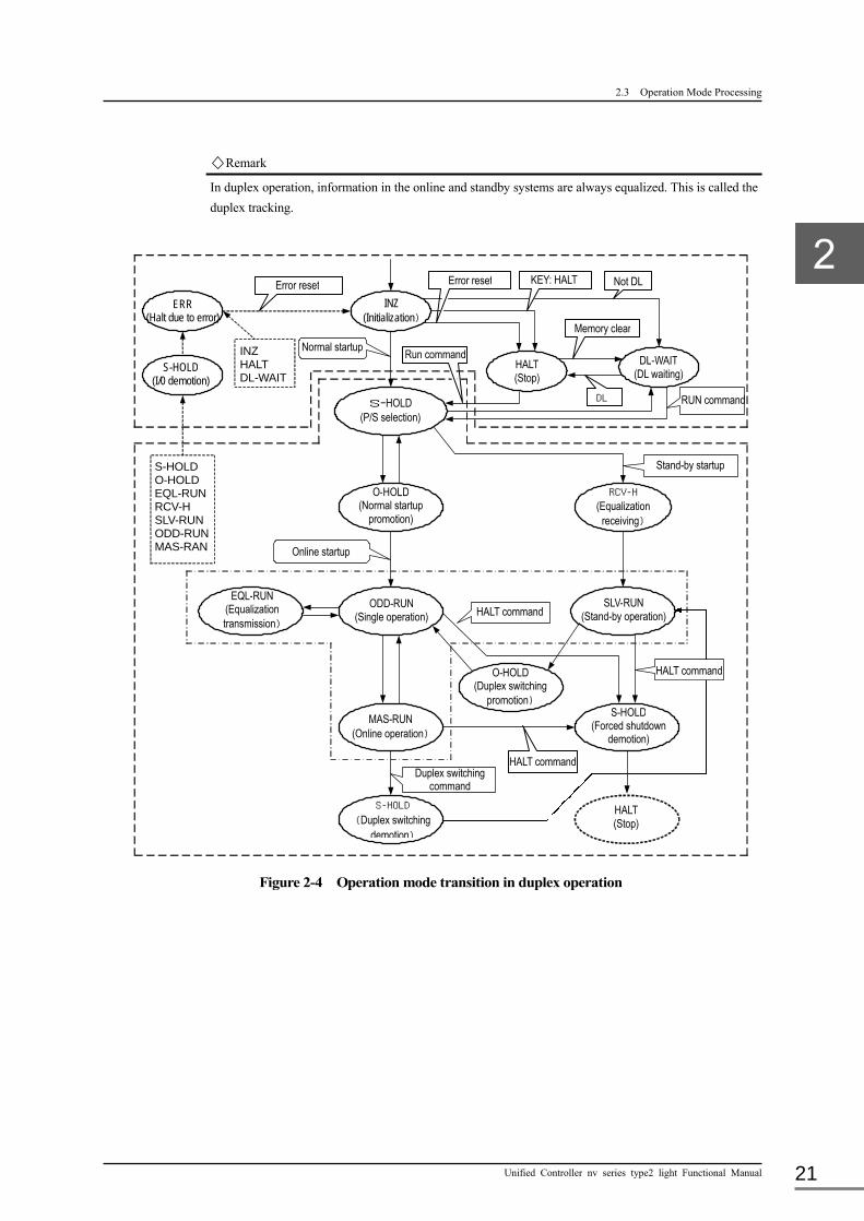
Remark
In duplex operation, information in the online and standby systems are always equalized. This is called the
duplex tracking.
Figure 2-4 Operation mode transition in duplex operation
ERR (Halt due to error)
S-HOLD (I/0 demotion)
INZ (Initialization)
S−HOLD (P/S selection)
HALT (Stop)
DL-WAIT (DL waiting)
INZ HALT DL-WAIT
Error reset
Normal startup
KEY: HALT Not DL
Memory clear
DL
Run command
Error reset
MAS-RUN (Online operation)
S-HOLD (Duplex switching
demotion)
O-HOLD (Normal startup
promotion)
ODD-RUN (Single operation)
EQL-RUN (Equalization transmission)
RCV-H (Equalization
receiving)
O-HOLD (Duplex switching
promotion) S-HOLD
(Forced shutdown demotion)
HALT (Stop)
SLV-RUN (Stand-by operation) HALT command
RUN command
Stand-by startup S-HOLD O-HOLD EQL-RUN RCV-H SLV-RUN ODD-RUN MAS-RAN Online startup
HALT command
Duplex switching command
HALT command
Chapter 2 Operation of Controller
6F8C1576 22
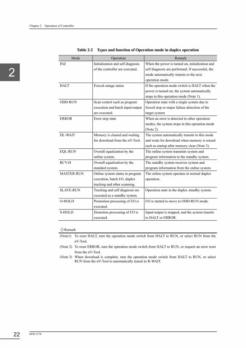
Table 2-2 Types and function of Operation mode in duplex operation
Mode Operation Remark
INZ Initialization and self diagnosis of the controller are executed.
When the power is turned on, initialization and self diagnosis are performed. If successful, the mode automatically transits to the next operation mode.
HALT Forced outage status If the operation mode switch is HALT when the power is turned on, the system automatically stops in this operation mode (Note 1).
ODD-RUN Scan control such as program execution and batch input/output are executed.
Operation state with a single system due to forced stop or major failure detection of the target system.
ERROR Error stop state When an error is detected in other operation modes, the system stops in this operation mode (Note 2).
DL-WAIT Memory is cleared and waiting for download from the nV-Tool.
The system automatically transits to this mode and waits for download when memory is erased such as startup after memory clear (Note 3).
EQL-RUN Overall equalization by the online system.
The online system transmits system and program information to the standby system.
RCV-H Overall equalization by the standard system.
The standby system receives system and program information from the online system.
MASTER-RUN Online system status in program execution, batch I/O, duplex tracking and other scanning.
The online system operates in normal duplex operation.
SLAVE-RUN Tracking and self diagnosis are executed as a standby system.
Operation state in the duplex standby system.
O-HOLD Promotion processing of I/O is executed.
I/O is started to move to ODD-RUN mode.
S-HOLD Demotion processing of I/O is executed.
Input/output is stopped, and the system transits to HALT or ERROR.
Remark
(Note1) To reset HALT, turn the operation mode switch from HALT to RUN, or select RUN from the nV-Tool.
(Note 2) To reset ERROR, turn the operation mode switch from HALT to RUN, or request an error reset from the nV-Tool.
(Note 3) When download is complete, turn the operation mode switch from HALT to RUN, or select RUN from the nV-Tool to automatically transit to R-WAIT.

2.4 Scan Processing
Unified Controller nv series type2 light Functional Manual 23
2.4 Scan Processing
High-speed scan and main scan are provided with independent scan cycles. The sub-scheduling
function allows the main scan running in a cycle of integral multiple of the set value.
As shown below, operations that are repeated in a cycle, such as batch I/O, standard I/O, user
programs and duplex tracking, can be set as the scan cycle.
2.4.1 Scan processing
①Batch input
processing
③Standard input
processing
②Program execution ③Standard output
processing
①Batch output
processing
④Duplex tracking
processing
① Batch input processing
In batch input/output, data is transferred between the user program and device to control (I/O
module) in block.
The type2 light controller executes input processing before a user program, and output
processing after the user program.
The input data is stored in the I/O variable input register (IW), and the data stored in the I/O
variable output register (QW) is output.
(For details on the batch input/output operation, see Chapter 5 I/O Input/Output.)
② User program execution
8 user programs are executed in the high-speed scan, and 64 user programs in the main scan
in order according to the task entry number.
The use program includes the event program which is executed according to the occurrence
of a specified event.
(For details of program execution, see Chapter 3 Tasks and Program.)
③ Standard input/output
The standard input/output processing is executed according to the tag information (PV, LP,
PB, SEQ, TC, T, C) registered in advance.
The processing includes the input and output of instrument control specific analog signals
(engineering variables, filtering, etc.) and digital signals (button operation and lamp
indication).
(For details of input and output, see Chapter 6 Standard Input/Output.)

Chapter 2 Operation of Controller
6F8C1576 24
④ Duplex tracking
In duplex configuration, the information (e.g. programs and real data including local and tag
variables) in the online system is written in the standby system for equalization. This is called
the duplex tracking.
The information subject to equalization includes the prerequisite information and information
that can be selected by the user.
(For details of equalized information, see Section 2.9 Equalization of Duplex Memory.)
2.4.2 Scan synchronization processing
While the scan period executes user programs and batch input/output, there is other standard
processing synchronization with a scan. It is not necessary to consider the standard processing in
ordinary conditions, but because of operation using a large number of tags, care is required when
MS scan cycle is short.
Scan processing
Standard processing
⑤Tag transfer processing
The tag information updated in ② user programs and ③ standard input/output is transferred to
the OIS.
⑥OIS message processing
Alarms in ③ standard input/output, FI/FO change, changes in tag parameters of the tools and
the OIS are sent to the OIS for entry in the alarm list and history screen. The processing time
is nearly zero when there is no status change (alarms, etc.).
・For the actual scan processing run time, see 7.2.1 Task run time measurement.
① ③ ② ③ ① ④
⑤Tag transfer ⑥OIS message processing
2.5 Duplex Operation
Unified Controller nv series type2 light Functional Manual 25
2.5 Duplex Operation
2.5.1 Power on start-up
In duplex configuration, the primary and secondary slots are determined in advance according to
the location of controllers. The left slot is the primary side and the right slot is the secondary side
in the duplex chassis (BU22). Although the online system is allocated to the controller turned on
first, and the standby system to the controller turned on later in duplex system, when the primary
and secondary sides are turned on simultaneously, the online system is allocated to the primary
controller, and the standby system to the secondary controller.
2.5.2 Power recovery operation
In duplex configuration, duplex operation resumes by transferring all information from the
online to standby systems for equalization when the power is recovered, regardless of long or
short interruption. This is called the overall equalization.
2.5.3 Target system monitoring
The target system is always mutually monitored during duplex operation.
The monitoring includes the current operation, self-diagnosis result, duplex tracking status, and
implementation status of the target system.
The online system starts single operation (single system operation) when the monitoring result
indicates an error in the standby system. The standby system is automatically promoted to the
online system only when the monitoring result indicates the complete shutdown of the online
system. Otherwise, the standby system keeps the current status.
2.5.4 I/O status monitoring
I/O modules, nodes, and loops are subject to regular I/O status monitoring.
When an error is found in part of I/O modules, the online system is not switched, but the error is
reported to the OIS which, in turn, stops the relevant tag operation in the standard input/output,
or the relevant input/output processing in the batch input/output, and continues operation.
The online system is switched in the event of failure in both TC-net I/O loops or all nodes.

Chapter 2 Operation of Controller
6F8C1576 26
2.5.5 Network monitoring
The Ethernet communication is monitored.
The online system is switched when the Ethernet communication stops
2.5.6 Download operation
In duplex configuration, overall equalization is performed to equalize the information in both
systems. The information in memory of the controller that starts first is copied to the controller
that starts later during overall equalization. The batch download is, therefore, to be performed in
the controller to start first. The memory of the controller to start later must be cleared before
startup as the standby system. The program downloaded to the online system during duplex
operation is automatically copied to the standby system.
(For details, see 2.9 Equalization of Duplex Memory.)
Remark
The type2 light controller has original processing of standard-input/output processing etc. for an interface
with OIS-DS. In case of duplex system configuration, it is necessary to set MS scan cycle later than
300ms.

2.6 Causes of Duplex Switching
Unified Controller nv series type2 light Functional Manual 27
2.6 Causes of Duplex Switching
The online system is switched to the standby or vice versa, and one of two systems starts single
operation when the other stops. This section describes switching factors.
2.6.1 Forced switching
The online and standby systems switch when the switching command is issued from nV-Tool.
When HALT mode is set on the online system, the current standby system starts operating as a
single system. When HALT mode is set on the standby system, the current online system
switches to single system operation, but continues scanning.
Switching is enforced when the current scan processing is completed, and the new online system
resumes scanning.
2.6.2 Major failure of the controller
When major failure is detected in the controller, error down and duplex switching occur.
The factors of major failure include the following. Some causes error down, and others cause
fallback.
・ Hardware error
・ I/O access error
・ Program execution error
Switching, enforced when one of the above major errors occurs, would stop output halfway, and
start from the beginning when the switching is completed.
2.6.3 All station error of I/O
Error down and duplex switching occur when all I/O's connected to the controller becomes
inaccessible.
The TC-net I/O has a duplex loop structure for high redundancy. Also, sufficient considerations
have been made in terms of design such as insulated optical connection and the external factor.
2.6.4 Major failure of Ethernet
Duplex switching occurs due to an error of the communication board or an error of the Ethernet
network system.
Be careful because duplexed IP addresses may affect whole network system.

Chapter 2 Operation of Controller
6F8C1576 28
2.7 Memory Management
The type2 light has program information in the memory on its controller. Following explains the
functions the memory.
2.7.1 Memory clear
There are 2 types of memory clear functions; the function to initialize the entire memory of the
controller, and the function to clear the downloaded information. The former memory clear is
used when the controller is replaced. The latter memory clear is used to clear only the
downloaded information without turning off the power.
■ Memory clear for initialization of entire memory (by switch setting)
Turn off the power of the controller, turn on dip switches 7 and 8 on the front panel, and turn on
the power of the controller again. The memory is cleared.
When memory clear is complete, the HALT LED blinks. After memory clear is finished, turn off
the DIP switches 7 and 8 on the front panel, and turn on the power again. The memory is ready
for download.
Memory clear by DIP switch setting also clears the "record of operating time." For details of DIP
switch, see 1.4.4 Mode setting switch.
■ Memory clear for initialization of entire memory (by nV-Tool operation) When memory clear is specified in the nV-Tool, memory clear is executed as in the setting of the
dip switch above. When memory clear is complete, the system enters the download wait state.
Memory clear by nV-Tool operation does not clear the "record of operating time."
■ Log clear The system log information saved in the controller is cleared.
In the nV-Tool, select the logs to delete, and make a clear request. Only the logs of the specified
type are cleared.
Note
・Forced memory clear is required when the memory error such as ECC error is not eliminated. Clear the memory using DIP switch.
・The operation time is integrated operation time since the controller hardware was turned on for the first time, and the information is used for life diagnosis. Do not clear it unnecessarily for quality control reasons.
◆Important
• After memory clear by switch setting is finished, turn off the DIP switches 7 and 8 on the front panel by all means, and turn on the power again.

2.7 Memory Management
Unified Controller nv series type2 light Functional Manual 29
2.7.2 Defragmentation
Defragmentation is a function that relocates the information dispersed in the internal memory to
regenerate continuous areas, just as defragmentation of general PCs.
A continuous space, suitable for the size of downloaded program, is allocated in memory area. If
the space is greater than the program, unused space remains as a small free space. When the
program is deleted, the space containing the program is emptied. When this is repeated, small
fragmented spaces increase, and the used and free spaces crisscross as a meshed pattern. The
overall free space is sufficient, but continuous space for storing programs is scarce, and
programs cannot be downloaded.
Defragmentation resolves this problem by adjusting the meshed pattern as continuous used space
and continuous free space to allow programs to be downloaded.
Remark
Repeated addition and deletion of local variables used by user applications will also cause memory fragmentation. Defragmentation is executable for these local variables.
2.7.3 Backup/Restore
The controller has the memory backup/restore functions. They are the functions to save and
restore the memory content of the controller as a memory image.
■ Backup The memory of the controller can be backed up in the hard disk of nV-Tool.
■ Restore The memory backed up in the hard disk of nV-Tool can be written in the controller.
If restore is cancelled, the controller cannot perform normal operation. Perform memory clear
again, and restart restore.
In the controller, internal initialization is executed after restore is complete or cancelled. Wait for
30 seconds or longer after completion before the next processing or operation.

Chapter 2 Operation of Controller
6F8C1576 30
2.8 Tag Management
2.8.1 Tag support
The type2 light controller uses the tag function supported in the CIEMAC-DS series.
Tag types and functions supported in PCS-DS and unified controller V series L controller are the
same tag available.
(For details of the tag, see Chapter 6 Standard I/O.)
2.8.2 Connection to OIS-DS
The type2 light controller exchanges tag information with OIS-DS, HMI of CIEMAC-DS series.
Tag information contains the process tag and system tag information, which are informed to
OIS-DS via the ONS communication function.
Figure 2-5 Data flow between the controller and OIS
type2 light (PUM21)
OIS-DS
Process tag
System tag
ONS communication
Standard I/O
RAS operation
Communication
Ethernet
Controller

2.9 Equalization of Duplex Memory
Unified Controller nv series type2 light Functional Manual 31
2.9 Equalization of Duplex Memory
Dualization of the unified controller nv series is implemented in a redundant system consisting
of an online system and a standby system. When switching is required, control is handed over to
the promoted standby system for continuous operation. The standby system, therefore, needs to
hold the same memory with the online system. This is called the memory equalization
(“equalization”).
2.9.1 Full equalization
The entire content of the memory of online is copied before the controller starts up and starts
operating as standby. This is called full equalization.
Until this equalization is complete, redundant configuration has not been established. The online
side is in equalization transmission, and the standby side is in equalization reception. During this
time, the operation of the online is the same as single system operation.
Full equalization is automatically executed when the power of the standby controller is turned on
or when the mode changes from the HALT mode to RUN mode.
2.9.2 Duplex tracking
In duplex operation, the memory of the online and standby systems always needs to be equalized.
Namely, when the memory of the online system changes, the memory of the standby system
must also change. This equalization of memories is called the duplex tracking.
As part of high-speed or main scan, the duplex tracking is performed in every scan cycle.
The next tale shows the data subject to duplex tracking.
Table 2-7 Duplex tracking data EA No. Name Use Transmission timing
0 Instance variable Program's local variable (retained) High-speed/Main scan 4 User variable Variables defined by the user Main scan 10 Tag instrument scan
for variable (data) PV_DATA Indicator variable LP_DATA Controller variable PB_DATA Pushbutton variable TC_DATA Timer/counter variable
High-speed/Main scan
SQ_DATA Sequence operation equipment T_DATA Timer variable C_DATA Counter variable R_PARA Generic parameter (real) W_PARA Generic parameter (integer)
Main scan
Remark
In addition to the data other than those in the above table, the data necessary for a part of standard processing is trucked.

Chapter 2 Operation of Controller
6F8C1576 32
2.9.3 User tracking
Aside from the duplex tracking where data subject to equalization is fixed, any data and
parameters may be equalized as required. This is called the user tracking, and executed in the
same cycle with the duplex tracking.
The table below shows the variables available for the user tracking.
Table 2-8 User tracking data
EA No. Name Use Transmission timing 5 I/O variable Batch I/O register (IW/QW) High-speed/Main scan
can be selected. 7 Tag instrument variable (Parameter)
PV_PARA Indicator variable LP_PARA Controller variable PB_PARA Pushbutton variable SQ_PARA Sequence operation equipment P_PARA Polygonal line variable T_PARA Timer variable C_PARA Counter variable TC_PARA Timer/counter variable DB_PARA Data block variable
10 Tag instrument variable (data)
DW Generic register
Note
・ In the first scan from switching, data from I/O is input in the input register (IW) in batch input processing, the user application operates based on this data, and the result of operation is output to the output register (IQ), and then to I/O in batch output processing. When all I/O variables are processed in this flow of operation, duplex tracking of I/O variables is not necessary. When a conditioned application is executed, however, the result of operation may not be output to the output register (QW), and the output data in batch output processing is indeterminate. To prevent this, the I/O variable that falls under the condition described above is registered to the user tracking to be included in the duplex tracking.
・ Normally, tracking of the tag instrument variable (parameter) is not required because it is automatically equalized in partial equalization when the OIS-DS or nV-Tool changes a parameter.
When, however, the parameter is changed via user program, equalization is not performed. Necessary area should be specified for user tracking.
・ When the sum of duplex tracking processing time and other scan processing time exceeds the specified scan cycle time, a minor error of scan congestion is generated. If the scan congestion continues for more than three scan cycles, the error turns to a major error and causes switching.
・ Do not register the user tracking greater than the maximum tracking size. Otherwise, the duplex system will shut down by an error.
・ The tracking size can be checked with the tracking load indication areas (ZD56, ZD58) of the system variable (ZW).
(See Appendix A.2 List of System Variables.)
2.9 Equalization of Duplex Memory
Unified Controller nv series type2 light Functional Manual 33
2.9.4 Partial equalization
Predefined data is equalized in every scan cycle in duplex or user tracking. In addition, the data
in the online system is automatically equalized when changed. This function is called the partial
equalization.
The partial equalization is performed when OIS-DS changes tag parameters, or nV-Tool
downloads programs or changes tag parameters.

34
Chapter 3 Tasks and Programs This chapter outlines the user programs executable in the unified controller nv series type2 light
controller (“type2 light controller”).
3.1 Tasks and Programs ··························································· 35
3.2 Task Types ······································································· 37
3.2.1 Event task (EV) ····················································· 37
3.2.2 I/O interruption task (IP) ········································· 38
3.2.3 Scan-related task (HS/MS) ······································ 38
3.3 Task Execution Control ······················································· 39
3.3.1 Task execution based on priority ······························· 39
3.3.2 Execution of event tasks ·········································· 39
3.3.3 Execution of event tasks for I/O interruption ··············· 42
3.3.4 Execution of scan ·················································· 42
3.3.5 Sub-scheduling and grouping ··································· 43
3.4 Task Error Monitoring ······················································· 45
3.4.1 Task errors ··························································· 45
3.4.2 Program errors ······················································ 46
3.4.3 Program fallback ··················································· 47
3.4.4 Task error processing ·············································· 48
3.5 Program Download ···························································· 49
3.5.1 Detection of program download ································ 49

3.1 Tasks and Programs
Unified Controller nv series type2 light Functional Manual 35
3.1 Tasks and Programs
The task is composed of one or more programs according to the purpose of processing as shown
in Figure 3-1.
Figure 3-1 Basic concept of task
■ TASK
The task is a unit of program execution. The controller calls and executes programs in units of
task. Any executable program can be registered in the task.
■ Task entry
The task entry is the entry for a program. It consists of an instruction to call the program, and is
automatically created when the program is registered.
The main scan task can contain 64 task entries, the high-speed task 8 task entries, and other tasks
one task entry.
The registered task entries can be viewed on the nV-tool task entry screen.
FunctionFunction
block
Program
Program
Function
Function
Function
Function/function blockTasks Programs
Function block
Function block
Task entry
Task entry

Chapter 3 Tasks and Programs
6F8C1576 36
■ PROGRAM
The main program for a task entry can be created by the user using LD, SFC, FBD or ST
language. It may be composed of a combination of function blocks and functions.
Remark
・LD language: Describes the sequence circuit with contact and coil instructions.
・SFC language: Describes the order sequence.
・FBD language: Holds functions in a block, and allocates parameters to data and addresses.
・ST language: Uses a text description format similar to PASCAL or C language.
■ FUNCTION_BLOCK
The function of a function block represents the program which retains internal instances (e.g.
static variables, temporary variables, controller variables) and operation data. The function
includes the timer and PID instructions which are required to retain previous values. The
function block can be registered in the user library, and call the function.
■ FUNCTION
The function represents the arithmetic program which does not require internal instances (only
temporary variables are available). General functions such as trigonometric function, and
functions for four arithmetic operations, conversion and comparison are included. The function
can be registered in the user library.
Remark
・POU (Program Organization Unit) The program structure and language comply with IEC 61131-3. Programs, functions and function blocks are managed in POU. This makes it possible to treat POU as a part, and use programs, functions and function blocks in POU repeatedly.
UP to 1000 POUs can be registered in the type2 light controller.

3.2 Task Types
Unified Controller nv series type2 light Functional Manual 37
3.2 Task Types
The unified controller nv series type2 controller has two event task types (event and I/O interrupt
tasks) and two scan task types (high-speed and main scan tasks).
3.2.1 Event tasks (EV)
There are 8 event tasks, each of which is allocated with a different system event.
Table 3-1 Event tasks
Type Condition No. of tasks
No. of programs
Concept
Event task (EV)
Executed in every system event.
8 1
The following table shows the type and role of event tasks.
Table 3-3 Event task types
Entry No. Execution condition Startup condition Processing details 0 Initialization Starts up at power recovery after
long interruption when changing from HALT to RUN.
Necessary processing for system startup or power recovery after long interruption is executed.
1 Initialization after short interruption
Starts up at power recovery after short interruption.
Necessary processing for power recovery after short interruption is executed.
2 Error down Starts up at shutdown of the system in a single system configuration due to error.
Error processing
3 Duplex switching Starts up when changing from standby to online.
Necessary processing for initialization of duplex switching is executed.
4 I/O fallback Starts up when I/O error is detected in batch I/O.
Processing assuming the effect of fallbacked I/O is executed.
5 Program fallback Starts up when program fallback occurs.
Processing assuming the effect of fallbacked program is executed.
6 I/O fallback recovery Starts up when I/O recovers to normal from fallback.
Processing assuming the effect of fallbacked I/O starting normal operation again is executed.
7 Reserved - -
EV7
EV0
Event 7
Event 0

Chapter 3 Tasks and Programs
6F8C1576 38
3.2.2 I/O interruption task (IP)
When an I/O modules causes an interruption, the associating task registered in advance is
activated. The association between I/O modules and tasks can be defined with nV-Tool. A total
of 16 I/O interrupt tasks are provided for 16 types of I/O interruptions.
Table 3-1 I/O interruption task
Type Condition No. of tasks
No. of programs
Concept
I/O interruption task (IP)
The task executed according to interruption request when I/O data change is detected.
8 1
3.2.3 Scan-related task (HS/MS)
There is one high-speed scan task with 8 programs and one main scan task with a program.
Both types of tasks execute programs in the order of their registration in one scan cycle. In the
main scan, sub-scheduling can be specified for each program, and the scan cycle can be extended
by the integral multiple.
The high-speed scan task has priority to the main scan task, and can interrupt the main scan
during execution.
Table 3-2 Scan task
Type Condition No. of tasks
No. of programs
Concept
High-speed scan task (HS)
Executed in high-speed scan cycles
1 8 Scan cycle: 0 or 10 to 500ms (in 1 ms)
Main scan task (MS)
Executed in main scan cycles
1 64 Scan cycle:100 to 10000ms (in 10ms)
IP7
IP0
I/O interrupt. 7
I/O interrupt. 0
HS 7
HS 0 1 Scan
MS 63
MS 0 1 Scan

3.3 Task Execution Control
Unified Controller nv series type2 light Functional Manual 39
3.3 Task Execution Control
3.3.1 Task execution based on priority
Control tasks follow the priorities. Tasks with higher priority are executed in preference to tasks
with lower priority. This execution control is most obvious when a task with higher priority is
executed when a task with lower priority is being executed.
The example below shows the task execution based on priority.
① A task of the high-speed scan is executed while a task of the main scan is being executed.
The task of the main scan is suspended, and the task of the high-speed scan that has higher
priority is executed.
② An event in which an interruption event task with higher priority occurs while the task of the
high-speed scan is being executed, and the task of the high-speed scan is suspended and the
interruption event task is executed.
Figure 3-1 Example of task execution based on priority
3.3.2 Execution of event tasks
Event tasks have determined operation conditions. The following are some example of use of
each event task.
■ Event task for initialization (EV0)
This task is executed first when the power is turned on. Before other tasks are executed, this task
can initialize the system. When the event task for initialization is complete, the tasks of the scan
system are started.
High speed scan
Main scan
Event

Chapter 3 Tasks and Programs
6F8C1576 40
Figure 3-2 Operation example of a program for initialization
■ Event task for error down (EV2)
When a fatal error (major error) is found in self diagnosis, all current tasks are suspended, and
the event task for shutdown error (EV2) is activated, while the program (MS3) that is not
directly affected by the error is executed to the end. The suspended tasks are not terminated, but
the programs (MS4, MS5) scheduled to run are not executed.
Figure 3-3 Operation example of the event task (EV2) for error down
■ Event task for I/O fallback (EV4) /Event task for I/O fallback recovery (EV6)
These tasks are started up when an input/output error of I/O is detected in batch input/output and
when recovery from I/O fallback is detected.
Event
HS scan
Main scan
EV2
MS0
MS1
MS2
MS3
MS4
MS5
Error detected Error down
HS scan
Main scan
EV0
Power ON
Event
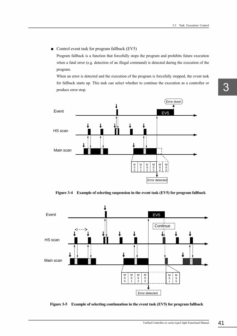
3.3 Task Execution Control
Unified Controller nv series type2 light Functional Manual 41
■ Control event task for program fallback (EV5)
Program fallback is a function that forcefully stops the program and prohibits future execution
when a fatal error (e.g. detection of an illegal command) is detected during the execution of the
program.
When an error is detected and the execution of the program is forcefully stopped, the event task
for fallback starts up. This task can select whether to continue the execution as a controller or
produce error stop.
Figure 3-4 Example of selecting suspension in the event task (EV5) for program fallback
Figure 3-5 Example of selecting continuation in the event task (EV5) for program fallback
Continue
Event
HS scan
Main scan
MS0
MS1
MS2
MS3
MS4
MS5
Error detected
EV5
HS scan
Main scan
Error detected
Event EV5
MS0
MS1
MS2
MS3
MS4
MS5
Error down
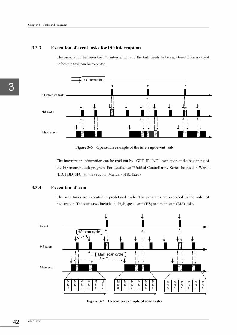
Chapter 3 Tasks and Programs
6F8C1576 42
3.3.3 Execution of event tasks for I/O interruption
The association between the I/O interruption and the task needs to be registered from nV-Tool
before the task can be executed.
Figure 3-6 Operation example of the interrupt event task
The interruption information can be read out by “GET_IP_INF” instruction at the beginning of
the I/O interrupt task program. For details, see “Unified Controller nv Series Instruction Words
(LD, FBD, SFC, ST) Instruction Manual (6F8C1226).
3.3.4 Execution of scan
The scan tasks are executed in predefined cycle. The programs are executed in the order of
registration. The scan tasks include the high-speed scan (HS) and main scan (MS) tasks.
Figure 3-7 Execution example of scan tasks
Event
HS scan
Main scan
M S 0
M S 1
M S 2
M S 3
M S 4
M S 5
M S 0
M S 1
M S 2
M S 3
M S 4
M S 5
M S 0
M S 1
M S 2
M S 3
M S 4
M S 5
HS scan cycle
Main scan cycle
HS scan
Main scan
I/O interrupt task
I/O Interruption

3.3 Task Execution Control
Unified Controller nv series type2 light Functional Manual 43
3.3.5 Sub-scheduling and grouping
The scan cycle setting range is 10 to 500 ms for the high-speed scan, and 100 to 10000 ms for
the main scan. The program with fast operation is registered in the high-speed scan, and the
program with relatively slow operation in the main scan. When slower operation or the
distribution of execution load is required, sub-scheduling allows the execution cycle of a
program to be extended as shown in Figure 3-8. The default setting of the sub-scheduling is 1.
The execution cycle of the program in the main scan is found as follows:
Program execution cycle = Scan cycle x Sub-scheduling
Figure 3-8 Example of sub scheduling
As shown in Figure 3-9, when sub scheduling is specified, if a lot of programs exist in the same
cycle it causes congestion. The congestion can be avoided by adjustment of execution timing by
grouping.
When the programs are specified for grouping, program execution cycle can be adjusted (shifted)
by the multiple of integer number of a scan cycle for each group. The example to use sub
scheduling and grouping is indicated below.
In the example of Figure 3-9, sub-scheduling value 2 is set on the programs (MS0, MS1, MS2,
MS3 and MS4). It is found that from the execution status that not all programs complete their
execution in one scan cycle to cause congestion.
Sub-scheduling MS0 1
2
3
4
5
MS0
MS0
MS0
MS0
MS0
MS2
MS0
MS1
MS1
MS1
MS1
MS2
MS2
MS3
MS3
MS4
MS4
Scan cycle

Chapter 3 Tasks and Programs
6F8C1576 44
Figure 3-9 Example of sub scheduling and grouping - 1
In the next figure, setting each program to five grouping (0 for MS0, 1 for MS1, 2 for MS2, 3 for
MS3 and 4 for MS4) solves the congestion shown in the precedent example.
Figure 3-10 Example of sub scheduling and grouping - 2
◆Important
• Grouping determines timing when operation execution (RUN) starts. If the grouping setting is changed during operation execution (RUN), the change is not reflected.
• Sub scheduling determines execution timing for each scan. If sub scheduling is changed during operation execution (RUN), the change is reflected immediately. However, the phase relation with other programs is not necessarily the same as the relation when the operation execution (RUN) starts up. Changing the sub scheduling or grouping setting during operation execution (RUN) is not recommended.
Sub-scheduling
2
2
2
2
2
Grouping
0
1
2
3
4
MS0
MS1
MS2
MS3
MS4
MS0
MS0
MS0
MS0
MS0
MS1
MS1
MS1
MS1
MS1
MS2
MS2
MS2
MS2
MS3
MS3
MS3
MS4
MS4
1
2
3
4
Sub-scheduling
2
2
2
2
2
Congestion
Grouping
0
0
0
0
0
MS0
MS1
MS2
MS3
MS4
MS0
MS1
MS2
MS3
MS4
MS0
MS1
MS2
MS3
MS4
MS0
MS1
MS2
MS3
MS4
MS0
MS1
MS2
MS3
MS4
MS0
MS1
MS2
MS3
MS4

3.4 Task Error Monitoring
Unified Controller nv series type2 light Functional Manual 45
3.4 Task Error Monitoring
Task errors are monitored while the task is executed. The task error monitoring and actions
against errors are described.
3.4.1 Task errors
■ Scan congestion
The scan system task is executed repeatedly at the specified fixed cycle. If it takes too
long because of too much processing, it may not be completed within the specified
cycle. This state is called scan congestion.
When scan congestion is detected, it is recorded to the system log, and an alarm for
the minor error is generated.
If the cause of scan congestion is transient, successful recovery may be expected by
catching up with the delay after a certain period of time.
Possible causes of scan congestion are listed below in descending order from the most
impinging cause.
• The program is too large, or the number of turns in the loop is too many.
• The scan cycle setting time is not sufficient for the actual program execution time.
• The number of I/O interruptions is more than expected, causing the execution of the I/O
interrupt task to increase rapidly for a short period of time.
• A program containing a large number of instances is downloaded from nV-Tool.
• A large amount of data (variable) is read from an external computer.
■ Task stall
If scan congestion is not transient and continues, continuation of processing is impossible and
task stall occurs.
Task stall is caused when the next scan cycle does not start after three times the current scan
cycle.
When task stall occurs, error down of the controller occurs as major failure. In the duplex system,
the system switches to the standby.
Note
• Scan congestion may be transient, but congestion itself is not desirable. The scan time must be set with a margin so that congestion won't occur even with the effect of program execution due to interruptions and environment changes.
• The time required for a scan can be displayed on the nV-Tool. Set an appropriate cycle time based on the task execution time. For details of execution time, see 7.2 Execution Status Monitor in Chapter 7.

Chapter 3 Tasks and Programs
6F8C1576 46
3.4.2 Program errors
Program are checked for errors in instruction units. Some errors are subject to program fallback,
while others are simply posted. The types of errors are shown in the table below.
Table 3-4 Types of program errors
Error Program Fallback
(Note 1) Failure Level
(Note 2) ZW54 Bit No.
(Note 3) Illegal instruction ○ Major/minor failure 0 POU undefined ○ Major/minor failure 1 Stack error ○ Major/minor failure 2 Real number operation error - Caution 3 Memory reference boundary error - Caution 4 Execution boundary over error ○ Major/minor failure 5 - - - 6 - - - 7 Division error - Caution 8 BCD data error - Caution 9 Table operation error - Caution A Encode error - Caution B - - - C - - - D Non-numerical input - Caution E Operation result overflow - Caution F
Note
(Note 1) Program fallback works only when the controller parameter [program fallback] is set to [Yes]. Error down if it is set to [No]. For details on program fallback operation, refer to 3.4.3 Program fallback.
(Note 2) Minor failure if program fallback is selected. Major failure if error down is selected. (Note 3) Program errors are indicated by system variables ZW53 and ZW54. F 1 0
ZW53 1 if an error occurs F E D C B A 9 8 7 6 5 4 3 2 1 0
ZW54 The meanings of each bit are shown in the table above.
3.4 Task Error Monitoring
Unified Controller nv series type2 light Functional Manual 47
3.4.3 Program fallback
Program fallback is to terminate a user program which cannot continue operation due to an error,
while allowing other user programs to run.
The purpose is to quarantine the error by terminating the affected program, regardless of the
cause of error, whether it is in the program or an external device such as the memory or I/O
device.
When program fallback is required, the event task (EV5) is automatically activated for an
appropriate error processing.
The following errors will cause program fallback:
• Illegal instruction : The instruction code is illegible.
• POU not found : The POU is not found.
• Stack error : Word diverting stack error
• Execution boundary over error : Attempted operation exceeds the program area.

Chapter 3 Tasks and Programs
6F8C1576 48
3.4.4 Task error processing
The post processing of task stall or program error depends on the duplex or single configuration.
Table 3-5 shows the task error processing.
Table 3-5 Task error processing Configuration
Cause
Duplex Single
Online Standby
Task stall Shuts down and switches to standby.
Single operation to continue execution.
Shuts down.
Program error with program fallback (Default setting)
Shuts down and switches to standby.
Single operation to continue execution. Falls back when program error is detected.
Terminates the error program and continues other programs.
Program error without program fallback
Shuts down and switches to standby.
Single operation to continue execution. Shuts down when error is detected.
Shuts down.

3.5 Program Download
Unified Controller nv series type2 light Functional Manual 49
3.5 Program Download
User programs are downloaded in units of POUs which constitute task entries and programs, and
are stored in the code memory of the controller. The download and execution methods are
specified in the program download operation menu in advance during online (RUN).
Table 3-6 Program download operation menu Program download operation menu Description
□Download without previously downloaded files. Only corrected POUs are downloaded.
□Download all files All program POUs are downloaded.
□Operate with current local variables The current local variables are continuously used.
□Operate with initialized local variables Local variables are Initialized (variables without initial values are cleared to zero).
Note
・Allocate an optimum space for downloaded POUs in the code memory area. An empty space is
created when programs are deleted or altered, and filled with downloaded programs.
When alteration, deletion and download of programs are repeated, the used and empty spaces in the
controller code memory are gradually fragmented, and available area diminishes. The POU cannot be
downloaded if a suitable storage space is not found. This results in the status in which new programs
cannot be downloaded while the number of steps of all downloaded programs does not reach the
maximum number of steps. If this is the case, defragmentation helps reorganize the code memory.
3.5.1 Detection of program download
The current program can detect a downloaded user program during operation. A change (OFF to
ON) in bit 15 of system variable ZW52 indicates the program download.
(For details of system variables, see Appendix A.2 List of System Variables.)
Program download may not be detected depending on the selection pattern of the program
download operation menu in nV-Tool. Table below shows the criteria of detection.
Table 3-7 Detection of program download Detection
Menu Yes No Yes No
□Download without previously downloaded files. ― ■ ― ■
□Download all files ■ ― ■ ―
□Operate with current local variables ― ― ■ ■
□Operate with initialized local variables ■ ■ ― ―
■:Menu selection

50
Chapter 4 Variables Variables are memory that can be referred to by the program. They are classified into different types depending on the usage.
Variable names can be defined freely. There are pre-defined (reserved) names.
The value of a variable changes only upon pre-determined initialization, storage during program execution, or write from HMI, etc.
The types and details of the variables that can be used in Unified Controller nv series type2 light comply with IEC61131-3.
4.1 What is the Variable? ························································· 51
4.1.1 Types of the variable ················································· 51
4.1.2 Variable types ························································· 51
4.1.3 Variable classification ··············································· 52
4.1.4 Size ····································································· 53
4.1.5 Direct representation of variable ··································· 53
4.2 Initialization of the Variable ················································· 54
4.2.1 Initialization ··························································· 54
4.2.2 Initialization timing ·················································· 54
4.3 Tag Variable ····································································· 55
4.3.1 Tab variable reference method······································ 55
4.4 System Variable (ZW) ························································· 56
4.5 Inter-controller Transmission (MW, AW) ································· 56

4.1 What is the Variable?
Unified Controller nv series type2 light Functional Manual 51
4.1 What is the Variable?
A variable is a memory or memory area that can be referred to or changed by the program. By
defining a variable name, the variable provides means to access information including data
input/output, data read/write in a controller or between controllers, and inter-station data
transmission.
The user need to consider the variable type and effective range when defining a variable. This
section presents the variables used in the type2 controller.
4.1.1 Types of the variable
Variables are classified into local variables and global variables according to the effective range.
Global variables include controller variables and network variables.
As variable names, names pre-defined by the system and names defined by the program can be
used. A tag name defined as a tag with the names (atoms) of the parameters of the tag attached as
extension is included in the user variable names.
■ Local variable Local variable is a variable that can be used only by the program. It can be used as working memory in the program.
■ Controller variable Controller variable is a variable used globally. This variable is used to exchange data between different programs.
■ Station variable Multiple stations share the station variable, which is used for data transmission between modules.
■ Network variable Network variable is a variable shared among stations. This variable is used to exchange data between programs on different stations.
4.1.2 Variable types
Table 4-1 shows the variable types.
Table 4-1 Variable types Notation Type Bits Effective data range
BOOL Boolean 1 0, 1 INT Integer 16 -32768 to 32767 DINT Double precision
integer 32 -2147483648 to 2147483647
UINT Unsigned integer 16 0 to 65535 REAL Real 32 -3.40282×1038 to 3.40282×1038 TIME Timer 32 0 to 2147483647ms
(MAX: 24d/20h/31m/23s/647ms) WORD Word 16 0000 to FFFF DWORD Double word 32 00000000 to FFFFFFFF

Chapter 4 Variables
6F8C1576 52
4.1.3 Variable classification
Table 4-2 shows the variable classifications, i.e., local and controller variables.
Table 4-2 Variable classification
EA No. Variable type Variable name Use Definition
0 Local Instance variable Local variable of the program
(held)(tracking)
User
1 Local Temporary variable Local variable of the program (not held) User
2 Controller global
System register Control system area (ZW) Fixed
3 Local Instance variable Local variable for the program (held)(non-tracking) User
4 Controller global
User variable User: Variable type defined by the user User
5 Controller global
Batch input/output register IW/QW: Variable for batch I/O register User
7 Controller global
Tag variable (parameter) PV_PARA Indicator variable
LP_PARA Controller variable
PB_PARA Pushbutton variable
SQ_PARA Sequence operation equipment
P_PARA Polygonal line variable
TC_PARA Timer/Counter
DB PARA Data block
T_PARA Timer variable
C_PARA Counter variable
RTT_PARA DS scan parameter variable
Fixed
10 Controller global
Tag variable (data) PV_DATA Indicator variable
LP_DATA Controller variable
PB_DATA Pushbutton variable
SQ_DATA Sequence operation equipment
TC_DATA Timer/Counter
T_DATA Timer variable
C_DATA Counter variable
R_PARA Generic parameter (real)
W_PARA Generic parameter (integer)
DW Data register
MW Transmission register for inter-controller transmission
Fixed
9 Controller global
Inter-controller transmission
AW Reception register for inter-controller transmission
Fixed
12 Station global Direct I/O Direct I/O variable that can be accessed from the program User
13 Station global Station memory Variable for direct access to system bus module. User
Remark
・ “Definition” column User: The variable name and data type are defined by the user. Fixed: Variables registered in the system are used as the fixed variable. The use can
allocate any variable and data type to the fixed variable. ・The direct I/O variable has a I/O variable name suffixed with underscore (_). ・The direct I/O variable allows the user to reference data on the I/O module allocated to the batch I/O register or data on TC-net memory.

4.1 What is the Variable?
Unified Controller nv series type2 light Functional Manual 53
4.1.4 Size
Table below shows the variable size (memory capacity).
Table 4-3 Variable type and size
Variable type Size Local Local variable 68KW (including non -tracking)
Temporary variable 4KW
Controller
User variable 16KW
System variable 8KW
I/O variable 16KW
Tag variable 0.5MW
Inter-controller transmission variable
64KW
4.1.5 Direct representation of variable
The variable is referenced with two ways, variable name (name format) and direct representation
(address format). The reference with the direct representation is described below.
The direct representation uses an address format that combines the EA number and offset
address.
<Example> For the reference of DW00010, of which the EA number is 10 and the start offset
address is 112416 in the DW register, add 10 to the offset address to form a direct
representation as shown below.
%MW 10.112426
Offset address (W)
EA number
Sign for direct representation
The EA numbers and offset addresses of variables frequently used are listed in the table below.
Variable EA number Initial offset address (W)
IW/QW 5 0 R_PARA 10 40704 W_PARA 10 44816 DW 10 45472 MW 10 78240 AW 9 0
Remark
・For the EA number, see 4.1.3 Variable classification.
・The initial offset address is indicated in the “word No.” by registering the fixed variable on the controller
variable registration screen of nV-Tool.

Chapter 4 Variables
6F8C1576 54
4.2 Initialization of the Variable
4.2.1 Initialization
Initialization of the variable can be selected from the following initializing methods. Select the
initializing method appropriate for the use of the controller.
■ Initialization of global variable
Specify whether the global variable is cleared to zero or not (i.e. previous value is held) at the
transition of controller operation mode to RUN mode.
Whether to initialize the global variable is specified with the module parameter of nV-Tool.
(For details, see 7.1.1 Controller operation specification in Chapter 7.)
■ Initialization of local variable
Specify whether the local variable is cleared to zero or not (i.e. previous value is held) at the
transition of controller operation mode to RUN mode.
Whether to initialize the local variable is specified with the module parameter of nV-Tool.
(For details, see 7.1.1 Controller operation specification in Chapter 7.)
4.2.2 Initialization timing
Variables are automatically initialized as needed when the controller is turned on, etc.
Table 4-4 Initialization of the variables
EA No.
Name
Initialization details Short
interruption startup
Long interruption
startup HALT→RUN Duplex
switching
0 Local
Instance variable (tracking) Continued Continued/Zero clear (Note 2) Continued
1 Temporary variable (Note 1) Zero clear Zero clear - -
2 Global System register Initialization Initialization Initialization Initialization
3 Local Instance variable (non tracking) Zero clear Zero clear Zero clear Zero clear
4
Global
User variable Continued Continued/Zero clear (Note 2) Continued
5 Batch input/output register Continued Continued Continued Continued
7 Tag variable (parameter) Continued Continued Continued Continued
10 Tag variable (data) Continued Continued
(Note 3) Continued Continued
9 Inter-controller transmission Continued Zero clear Zero clear Continued
13 Station memory Continued Continued/Zero clear (Note 2)
Remark
(Note 1) The temporary variable is cleared or continuously used, should be initialized by the user program.
(Note 2) Cleared to zero or continued depending on the setting of the PU821 module parameter. (For details, see 7.1.1 Controller operation specification in Chapter 7.)
(Note 3) M mode is the tag control mode. Read-back data is set on “MV” of the LP tag and “FO” of the PB tag. No read-back can be specified on “FO” of the PB tag.

4.3 Tag Variable
Unified Controller nv series type2 light Functional Manual 55
4.3 Tag Variable
This section describes how to refer to the tag variable.
4.3.1 Tag variable reference method
Three methods are provided for referring the tag:
Example: Refer to the 100th button status (FI1) of the PB tag.
(1) Using the standard variable name (PB_DATA) array and atom (Note 1)
PB_DATA[100].FI1
(2) Using the tag number (BC001) and atom (recommended) (Note 2)
BC001.FI1
(3) Using the variable name (PB_DAT) and atom (Note 3)
Word No.: 53248 (PB initial address)
Data type: ARRAY [0.1279] of TYPEPB_DATA_DS
PB_DAT[100].FI1
That table shows the standard tag variables.
Table 4-5 Type and size of standard tag variables
Standard tag variable Meaning No. Tag number
(Note 4) Parameter Data PV_PARA PV_DATA Indicator 384 ○
LP_PARA LP_DATA Controller 128 ○
PB_PARA PB_DATA Pushbutton 512 ○
SQ_PARA SQ_DATA Sequence operation equipment 64 ○
TC_PARA TC_DATA Timer/counter 64 ○
DB_PARA DB_DATA Data block 128 ○
RTT_PARA - For real time trend registration 512 ×
T_PARA T_DATA Timer 256 × C_PARA C_DATA Counter 128 × P_PARA - Polygonal line table 128 ×
- R_PARA Real parameter 2048 ×
- W_PARA Integer parameter 640 ×
- DW Data register 32768 ×
- MW Transmission register for inter-controller transmission
1024 ×
- AW Receiving register for inter-controller transmission
65536 ×
Remark
(Note 1) Register the standard variable to be referred to on the controller variable registration screen.
(Note 2) Register the tag number of the tag to be referred to using the tag editor. (Note 3) Register the variable name, data type and word No. of a new variable to refer to the
tag on the controller variable registration screen. (Note 4) The PV, LP, PB, SQ, TC and DB tags can be referred to with their tag number. For
other tags, use the variable.

Chapter 4 Variables
6F8C1576 56
4.4 System Variable (ZW)
System variables are used by the program to exchange information with the controller. They can
be referred to by the program as controller global system variables (ZW). The controller
operation status can also be monitored on the nV-Tool screen using the system variable (ZW).
A system variable has an array structure represented by word, which is also called a ZW register.
For details, see Appendix A.1 List of System Variables.
4.5 Inter-controller Transmission (MW, AW)
Data is periodically (500 ms cycle) exchanged among the controllers connected to the control system LAN.
The MW variable represents the area of a local controller for transmitting data to other controllers. 1 KW is allocated to this area. The data written in this area is delivered to the AW area of other controllers.
The AW variable represents the area of a local controller for receiving data from other controllers.
64 areas of 1 KW are provided for controller numbers 1 to 64 (PC No.). The data transmitted
from a remote controller is written in the relevant area. The concept of inter-controller
transmission is illustrated in the figure below.
Figure 4-1 Concept of inter-controller transmission
Remark
・“Permit” and controller number “0” are the default setting of inter-controller transmission. Set the control number (1 - 64) on the module parameter. For the setting method, see Chapter 7 nV-Tool Support Function, 7.1.5 Others and Ethernet.
コントローラ-1
Controller 3 PC NO:3
Controller 4
Controller 1 PC NO:1
Controller 2
Controller 3
Controller 4
Controller 63
Controller 64
・ ・ ・ ・ ・ ・ ・ ・ ・ ・
Controller 1
AW register
MW register
Controller 2 PC NO:2
Controller 3
Controller 4
Controller 63
Controller 64
・ ・ ・ ・ ・ ・ ・ ・ ・ ・
Controller 2
AW register
MW register
Controller 1
Controller 2
Controller 63
Controller 64
・ ・ ・ ・ ・ ・ ・ ・ ・ ・
Controller 3
AW register
MW register
Controller 64 PC NO:64
Controller 1
Controller 2
Controller 3
Controller 4
Controller 63
Controller 64
・ ・ ・ ・ ・ ・ ・ ・ ・ ・
Controller 64
AW register
MW register
・・・・・・・・・・・
Control LAN
Controller 3
Controller 2
Controller 1 Controller 1
57
Chapter 5 Input/Output In the Unified Controller nv series type2 light controller (herein after called the “type2 light
controller”), there are batch input/output and direct input/output as methods to execute input/output.
This chapter describes the input and output of I/O data and related functions.
5.1 I/O Processing ·································································· 58
5.1.1 Batch I/O ······························································ 58
5.1.2 IQ register and I/O connection ····································· 58
5.1.3 I/O module and IQ register allocation ····························· 59
5.1.4 Direct I/O ······························································ 60
5.1.5 I/O interruption ······················································· 61
5.2 I/O Fallback ····································································· 62
5.2.1 I/O fallback ··························································· 62
5.2.2 I/O fallback procedure ··············································· 63
5.2.3 I/O recovery procedure ·············································· 63
5.3 I/O Error Monitoring ························································· 64
5.4 Continuation and Suspension of I/O Module Operation ··············· 64
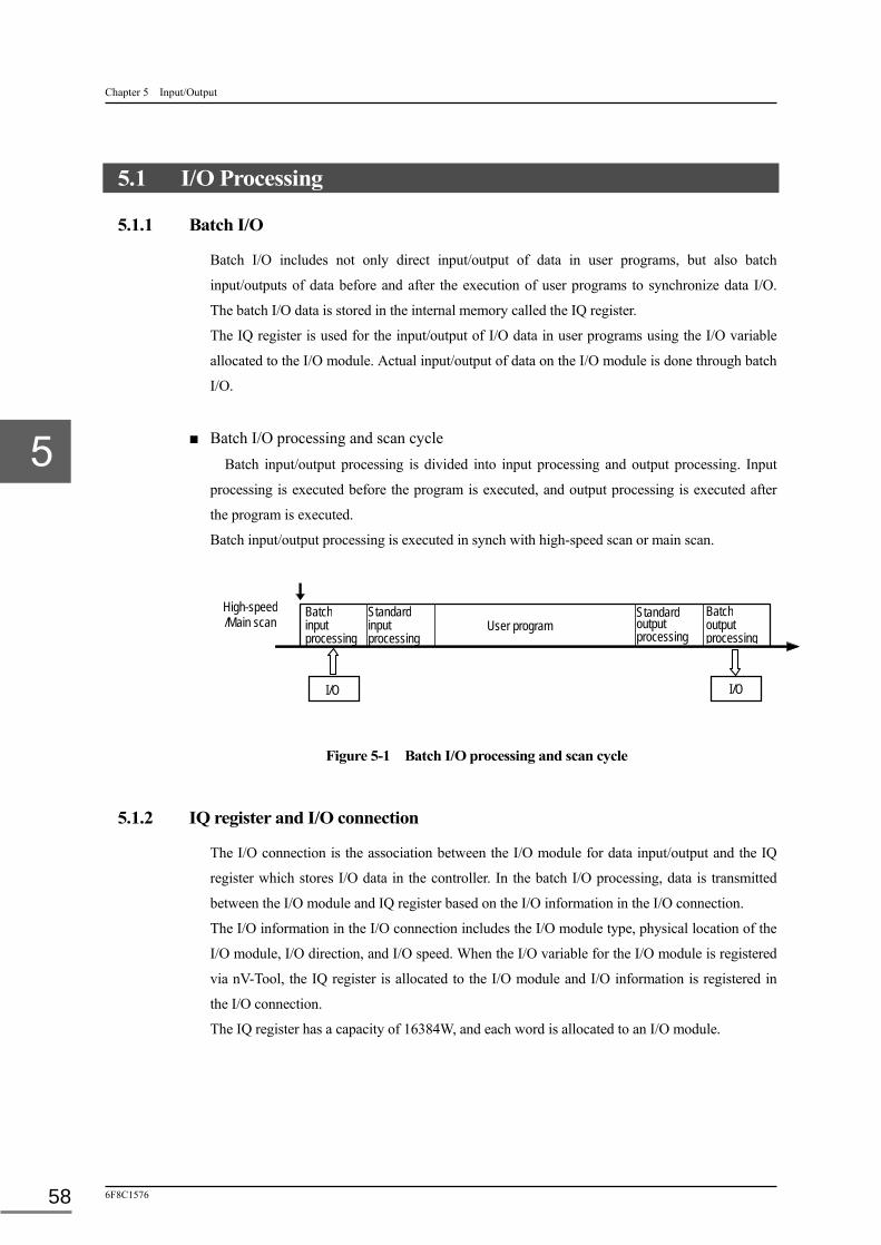
Chapter 5 Input/Output
6F8C1576 58
5.1 I/O Processing
5.1.1 Batch I/O
Batch I/O includes not only direct input/output of data in user programs, but also batch
input/outputs of data before and after the execution of user programs to synchronize data I/O.
The batch I/O data is stored in the internal memory called the IQ register.
The IQ register is used for the input/output of I/O data in user programs using the I/O variable
allocated to the I/O module. Actual input/output of data on the I/O module is done through batch
I/O.
■ Batch I/O processing and scan cycle
Batch input/output processing is divided into input processing and output processing. Input
processing is executed before the program is executed, and output processing is executed after
the program is executed.
Batch input/output processing is executed in synch with high-speed scan or main scan.
Figure 5-1 Batch I/O processing and scan cycle
5.1.2 IQ register and I/O connection
The I/O connection is the association between the I/O module for data input/output and the IQ
register which stores I/O data in the controller. In the batch I/O processing, data is transmitted
between the I/O module and IQ register based on the I/O information in the I/O connection.
The I/O information in the I/O connection includes the I/O module type, physical location of the
I/O module, I/O direction, and I/O speed. When the I/O variable for the I/O module is registered
via nV-Tool, the IQ register is allocated to the I/O module and I/O information is registered in
the I/O connection.
The IQ register has a capacity of 16384W, and each word is allocated to an I/O module.
I/O
High-speed /Main scan
Batch input processing
Standard input processing
User program
I/O
Standard output processing
Batch output processing

5.1 I/O Processing
Unified Controller nv series type2 light Functional Manual 59
Figure 5-2 IQ register and I/O connection
5.1.3 I/O module and IQ register allocation
The I/O connection is managed by I/O connection types, classified by the attributes of the I/O
module (type, I/O direction and I/O speed). The efficiency of batch I/O is increased by I/O
operation classified by I/O connection types. The range of IQ registers that can be allocated to
each of the I/O connection types is predefined, and the IQ register is allocated to the I/O module
based on this range. That is, the I/O variable cannot be specified outside the relevant range of IQ
registers. The starting number of the IQ registers and number of allocated registers can be
changed as required.
Table below shows the allocation range (default value) of IQ registers by I/O connection types.
Table 5-1 I/O module type and IQ register allocation
I/O module I/O connection type Top IQ register
number No. of IQ registers
I/O Interruptio
n I/O module connected via TC-net I/O loop
TC-net I/O digital input 0 768 Available TC-net I/O analog input 768 768 Available TC-net I/O digital output 1536 768 Available TC-net I/O analog output 2304 768 Available TC-net I/O special input/output 3072 3072 Available Reserved 6144 4704
I/O module connected via system bus
TC-net10 I/O 10848 1536 Available Station global I/O 12384 1536 Unavailable Intelligent serial I/O 13290 1024 Unavailable
I/O
I/O connection
I/O dataIQ register
IQ000
IQ16383
Program Batch I/O processing
IQ001IQ002IQ003IQ004
I/O
I/O
I/O
I/O module
I/O dataI/O dataI/O dataI/O data
I/O data

Chapter 5 Input/Output
6F8C1576 60
Remark
・Drives are not supported in the type2 light controller. ・The I/O interrupt task is used in the I/O modules with I/O interruption allowed. ・The batch I/O time is found by the following equation: Batch I/O time (µs) of TC-net I/O = No. of data words (W) 70 µs Batch I/O time (µs) of system bus module = No. of data words (W) 3 µs
5.1.4 Direct I/O
Direct I/O is to transmit data directly between the I/O module and user program without using batch I/O.
Direct input/output can directly input/output I/O module data without using batch input/output, and therefore can input/output the latest data (i.e. execute as an image).
Direct I/O is available for the Load/Store and LD instructions. The I/O address of the I/O module
can be specified with the I/O variable suffixed with underscore (_), or with the direct
representation (%MW).
Remark
・The TC-net I/O utilizes the remote I/O format, so the output terminal cannot be accessed or
operated directly. Data I/O is via the scan memory of the TC-net I/O.
・The internal memory of the I/O module connected via system bus can be directly accessed.
Figure 5-3 Direct I/O
System bus module
User program
Controller
I/O
I/O
TC-net I/O
Direct I/O instruction

5.1 I/O Processing
Unified Controller nv series type2 light Functional Manual 61
5.1.5 I/O interruption
The interrupt event task (IP task) is activated with the change of data in the TC-net I/O by
associating the IP task with the status change detection in the I/O module.
■ A maximum of 32 status changes in the I/O module of TC-net I/O can be registered.
The association of I/O module status change detection and interrupt event task can be
registered on the “Status Change Notification” screen for modular parameters of the type2
light controller (PUM21) using nV-tool. Table below shows the status change items for the
I/O module.
Table 3-9 TC-net I/O module status change items
Item Description
Status change detection Detection of status change at a specified point is registered (yes or no). When yes, the status change at the point is detected.
I/O module The I/O module of which status change is detected. (I/O module registered in the I/O node.)
I/O word number The word number of the I/O module of which status change is detected.
Detection mask (ON) (4-digit value in hex)
Only the status change to ON is detected. Specify the bit of word data (16 bits) to detect status change in hex. “1” for detecting status change, or “0” for not detecting status change. (Default value: FFFF)
Detection mask (OFF) (4-digit value in hex)
Only the status change to OFF is detected. Specify the bit of word data (16 bits) to detect status change in hex. “1” for detecting status change, or “0” for not detecting status change. (Default value: o)
IP task number The IP task to be activated when status change is detected (0 - 7).
Figure 5-4 I/O interruption and I/O interrupt tasks
I/O
I/O interrupt task (IP0)
Controller
I/O interrupt task (IP3)
1234
3132
Status change information
I/O
I/O interrupt task (IP7) I/O

Chapter 5 Input/Output
6F8C1576 62
5.2 I/O Fallback
I/O fallback and I/O recovery are used in the error processing during the batch I/O of the I/O
module. In either operation, a dedicated event task causes an interruption in the error processing.
5.2.1 I/O fallback
I/O fallback is to disconnect the I/O module containing an I/O error when I/O fallback is
specified, while continuing I/O for other I/O modules. When I/O fallback is not specified, the
controller shuts down due to an error.
Figure 5-5 illustrates the flow of batch I/O and I/O fallback.
Figure 5-7 Batch I/O and I/O fallback
Remark
・ I/O fallback is specified by controllers on the “Controller Operation Specification” screen of
nV-Tool for module parameters.
・ When I/O fallback is not specified for a controller, an error in the I/O modules cause the
controller to shut down.
・ When I/O fallback is specified for a controller, I/O fallback for the I/O node can be specified
on the “I/O Node” screen of nV-Tool for module parameters.
・ When I/O fallback is not specified for the I/O node, an error detected in the I/O module at the
I/O node causes the controller to shut down. ・ Default setting of I/O fallback of the type2 light controller is “enabled.”
Error log
MS task
1-2 Batch I/O
MS0 MS1
MS2
MS64
1-1
I/O module
Diagnostic task
2-1
2-2
2-3
1-1
I/O
I/O
ZW register
Event task(EV4)
Event task(EV6)
IQ register
I/O error
I/O recovery
・ ・ ・ ・ ・
1-2
1-1
1-3
1-3

5.2 I/O Fallback
Unified Controller nv series type2 light Functional Manual 63
5.2.2 I/O fallback procedure
I/O fallback in batch I/O is carried out in the order of steps 1-1, 1-2 and 1-3 below and also
shown in Figure 5-7.
1-1: Data is transmitted in batch mode between the IQ register and I/O module during ordinary operation. The user program writes and reads data on the IQ register.
1-2: When an error is detected in batch I/O, the error log and the error information (ZW) are updated, and the associated I/O module stops I/O.
For an error in the I/O module, the event task (EV4) is activated. (Note 1)
The module parameter set to “No fallback” causes the controller to shut down but EV4 does not startup. The module parameter set to “Fallback” starts up EV4.
1-3: In the event task (EV4), either I/O fallback or shutdown can be selected via operation of ZW307 during EV4 task).
If I/O fallback is selected, the error I/O module stops, while other I/O modules continue batch I/O, or stop by force (fallback) with the I/O fallback request instruction. (Note 2) (Note 3)
If shutdown is specified, the controller shuts down when an error is detected. In duplex configuration, the online and standby controllers switch to continue operation.
5.2.3 I/O recovery procedure
I/O recovery following I/O fallback in batch I/O is carried out in the order of steps 2-1, 2-2 and
2-3 below and also shown in Figure 5-7.
2-1: After I/O fallback, the associated I/O module or I/O node is periodically inspected to check for the recovery to normal status.
2-2: When the I/O module or I/O node recovers to normal status, the recovery log and error recovery information (ZW) are updated, and the event task (EV6) is activated for the notification of I/O recovery.
The event task (EV6) is also able to restore I/O of the I/O modules subject to forced I/O fallback in step 1-3 with the I/O recovery request instruction. (Note 2)
2-3: The I/O module or I/O node recovered by the event task (EV6) resumes batch I/O.
Remark
(Note 1) The error in the I/O module includes the failure of the I/O module or I/O bus. the error in the I/O node indicates the failure of the TC-net I/O interface or TC-net I/O
loop. I/O fallback is continued without the event task (EV4).
(Note 2) For details of the I/O fallback request instruction (IOFB_REQ) and I/O recovery request
instruction (IORC_REQ), see “Unified Controller nv Series Instruction Words (LD, FBD,
SFC, ST) Instruction Manual (6F8C1226).
(Note 3) If I/O fallback is specified in duplex configuration, switching does not occur.

Chapter 5 Input/Output
6F8C1576 64
5.3 I/O Error Monitoring
The status of each TC-net I/O component is monitored and diagnosed by the diagnostic function,
and the result is indicated on OIS-DS.
When an TC-net I/O error is detected or restored in batch I/O or periodical diagnosis operation,
the status is indicated in the I/O configuration field of the system screen of OIS-DS in terms of
I/O loop, I/O node, and I/O module, and the history is recorded.
For details of the errors, see Chapter 8 RAS Function and "High-Speed Serial I/O System TC-net
I/O Operation Manual" (6F8C1240).
5.4 Continuation and Suspension of I/O Module Operation
The TC-net I/O interface (SA911) operates as an I/O node of the TC-net I/O loop, and when an error occurs in that I/O node, all I/O modules under the node become inaccessible.
When the controller shuts down due to an error, the I/O nodes and I/O modules in the TFC-net I/O loop remain to be accessible even if control stops.
Such abnormal situations can be handled by setting countermeasures on the parameters of the output module using nV-Tool.
When continuation is specified for output, the last output status is retained, or when
discontinuation is specified for output, the output status is reset (0V, 0mA). The default setting is
continuation.
Remark
・There are output modules on which output status cannot be specified, but continuation is unconditionally specified for this type of output modules.

65
Chapter 6 Standard I/O The Unified Controller nv series type2 light inherits the standard input/output that has been
supported by L2 and L3 of the PCS-DS and Integrated Controller V series.
6.1 Tag Variables and Standard I/O Processing ······························ 66
6.2 Types of Tag Variables ························································ 67
6.3 Four Functions of Standard I/O ············································· 68
6.4 Details of Standard I/O Processing ········································· 70
6.5 Sequence Tag ···································································· 79
6.6 Process Alarm··································································· 79

Chapter 6 Standard I/O
6F8C1576 66
6.1 Tag Variables and Standard I/O Processing
The standard input/output function consists of PV processing, LP processing, PB processing,
SEQ processing, TC processing, T processing, and C processing.
Assuming general process control, the signal of an external sensor is first captured to PV
processing as an initial value. After that, an engineering unit conversion of the input value is
performed by PV processing, and the input value (PV) is inputted to PID processing (PID
command) of the program. PID processing calculates the operation amount according to the
setting value (SV) and specified control parameters and outputs the output value (MV) to LP
processing. LP processing performs output processing of the output value (MV) and outputs the
operation amount to external operation equipment.
The OIS has the indicator, integrator, controller, M/A operation equipment, and ratio relay tags
of the analog system and the pushbutton tag of the digital system. The tag information can be
displayed on the face plate and point display screen on the OIS's screen. The OIS exchanges tag
information with the tag instrument variables of the controller to enable display and setting by
the OIS.
Figure 6-1 Standard input/output processing of the controller
Controller Standard I/O processing
(tag variables)
) PV processing
Input value
LP processing
Output value
PB processing
Input value
Output value
TC processing
C processing
SEQ processing
T processing
Program
PID processing
Program
Digital processing
Program
Sequence processing
I/O s
can
mem
ory
PV
SV
MV
FI
FO
DI
DO
AO/PO
AI/PI
TAG
Push
butto
n
M/A
ope
ratio
n eq
uipm
ent
Ratio
rela
y ta
gs
Cont
rolle
r
Inte
grat
or
Indi
cato
r
Tim
er
Sequ
ence
r
Coun
ter
OIS
I/O
I/O
I/O
I/O

6.2 Types of Tag Variables
Unified Controller nv series type2 light Functional Manual 67
6.2 Types of Tag Variables
The next table shows the types of the tags used in standard input/output.
Table 6-1 Types of tags
Tag instrument variable
Tag Variables
No. of points
Up- date
Type Description
Indicator PV 384 ○ IND,AMM,PFI, TTL,WND
Instrument for analog input (instantaneous value/integration value) or pulse input (instantaneous value/integration value).
Controller LP 128 ○ PID,SPI,M/A, RS,TPI,SET, BLM,BLC,BMA,BMD
Instrument for analog output or pulse output. Always used in combination with the indicator variable.
Pushbutton PB 512 ○ SOV,MOT,MOV ,PB4,PB8,PB2 ,2PC,BT4,BT8 ,LP4,LP8
Instrument for digital input/output. Used in combination with the indicator variable as needed.
Sequence SQ 64 - SEQ Instrument for SFC management. Managed by the sequence dedicated command.
Timer/Counter TC 64 ○ TIM,CNT Instrument for the timer and counter. Data block DB 128 - DB1,DB8 Instrument for data setting and display Real parameter R 2048 - Treat as a variable, not an instrument.
Integer parameter W 640 -
Timer T 256 ○
Counter C 128 ○
Polygonal line table P 128 - DS scan parameter RTT 512 - Information for real-time trend
registered in the OIS.
Remark "Update" column ○: Updated by standard input/output processing. -: Not updated by standard input/output processing (for application). "Instrument pattern" column
The instrument pattern displayed on the OIS is determined based on the TYPE setting, and the corresponding standard input/output processing is performed.
“Description” column To use the indicator and controller together, the tag numbers (1 - 1024) of the indicator is required to
be registered in the tag of the controller. (For details, see Appendix C List of Process Tags, C.2 LP (Controller).)

Chapter 6 Standard I/O
6F8C1576 68
6.3 Four Functions of Standard I/O
Standard input/output processing consists of 4 functions; data input/output (tag variable update),
signal alarm, I/O error, and read-back. The 4 functions are executed depending on the type of the
tag variable. The following table shows the relations between the tag variables (updated by
standard input/output processing) and the 4 functions.
Table 6-2 Execution functions of tag variables
Tag variable
Data input/output
Signal alarm Device error Read-back
PV ○ ○ ○ - LP ○ ○ ○ ○ PB ○ ○ ○ ○
SEQ - ○ - - TC ○ ○ - - T ○ ○ - - C ○ ○ - -
○: Executed,-: Not executed (no corresponding function)
■ Data input/output function
This is a basic function of standard input/output processing. PV executes data input from I/O, LP
executes data output to I/O, PB executes data input/output to I/O, TC executes timer/counter
time, T executes timer time, and C executes counter time. The detailed processing of each tag
variable is described on the following pages.
Data input/output is performed in the PV, LP and PB tags. The I/O module or variable address is
required to be registered in the tag parameter (Input point variable name/output point variable
name).
Remark
・For input and output with the I/O module, select an I/O module from registered I/O modules, and register it to the tag I/O point variable name (PVA/MVA/IA/OA). For input and output with a variable such as batch I/O, register the variable address in the direct representation format. (For details, see Appendix C List o Process Tags, C.1 PV (Indicator), C.2 LP (Controller) and C.3 PB (Pushbutton).)
■ Signal alarm function
This function compares the result obtained by the data input/output function (e.g. PV value) and
the alarm condition (e.g. PV upper limit alarm), and sets the corresponding alarm if the alarm
condition is met. This is regarded as a sensor error, not the I/O module error, and input is
continuously updated.
The timer/counter tag sets an alarm when the alarm condition is met in comparison of input the
value (present value) with the set value (target value).
The alarm bit of the sequence tag is set directly with the SEQ instruction.

6.3 Four Functions of Standard I/O
Unified Controller nv series type2 light Functional Manual 69
■ Device error function
A device error means detecting major failure (system alarm) such as transmission disconnect
(module down) or ADC/read-back error in the I/O module and setting an alarm of the tag
variable as an error of the module (device).
Device errors are monitored in the PV, LP and PB tags. To monitor device errors, information on
the I/O module location (node number, unit number, slot number) is required to be registered.
The device error detected is indicated as the PV I/O error (PDE) in the PV tag, MV error (MVE)
in the LP tag, or I/O error (IOE) in the PB tag.
Note
・The MV error (MVE) of the LP tag is not automatically reset. The even when the cause of error is recovered for safety reason. The operator needs to confirm (reset) the error.
・When a device error is detected, the standard I/O stops updating (except for the PB tag). ・When an output error (e.g. MV read-back error) is detected, automatic control stops in principle.
■ Read-back function
For LP and PB, when control mode =M, the output read-back value from I/O is reflected to
MV and F0, and made equal to the actual output value from I/O. This processing prevents rapid
variation of output when the control mode changes to A or C.
To perform the read-back function, information on the I/O module location (node number, unit
number, slot number) is required to be registered.
Note
・With the AO module which is not equipped with the read-back circuit, the read-back and device error functions are not available. In this case, information on the I/O module location (node number, unit number, slot number) is required to be registered. (For details, see Appendix C List of Process Tags, C.2 LP (Controller), and C.3 PB (Pushbutton).)

Chapter 6 Standard I/O
6F8C1576 70
6.4 Details of Standard I/O Processing
The data input/output functions (standard input/output basic functions) for tag variables are
shown below.
■ PV processing
●Analog instantaneous value conversion
Normalization, temperature pressure correction, filtering, and engineering unit conversion are
executed in the following order.
① Sensor check
When the ADC count value diverts from the normal range, the signal from the
sensor/transmission equipment is regarded as disconnected. This state is a sensor error.
When no signal is inputted to the input terminal for analog input, the ADC count changes
to the full count value or zero count value depending on the hardware characteristics upon
the opening of the input terminal. In this case, the final converging count value and
converging speed are determined by the hardware characteristics of the analog input
module.
Generally, a sensor error occurs when the ADC count value becomes the full scale (4095
for 12-bit ADC) or when the input voltage is 0.7V (equivalent) or less. The former is
called an upper limit error, and the latter is called a lower limit error.
Whether to execute a sensor check can be specified for upper limit check and lower limit
check independently.
Remark
・The ADC count value is set on the raw count value (DRAW) of the tag. ・The alarm is generated and the PV is updated when a sensor error is detected.
The PV update and alarm generation can be specified by combining the PV upper/lower limit sensor error suppress (UIL/UIH) and update during sensor error (PVIR). The table below shows the association between setting and operation.
Setting Operation during sensor error
UIL /UIH
PVIR Present value
(PV) PV processing error
(PRE) Sensor upper/lower limit alarm
(PVIH/PVIL) OFF OFF Retained ON ON
OFF ON UP/DOWN OFF ON ON - UP/DOWN OFF OFF UP/DOWN of the present value (PV) depends on the type of I/O module.
② Normalization
Normalization means converting the ADC count value (hereafter called the “raw count
value (DRAW)”) to a percentage value.
The raw count value (DRAW) is determined based on the type of ADC of the input
module. For 12-bit ADC, the range of the count value is 0 to 4095.

6.4 Details of Standard I/O Processing
Unified Controller nv series type2 light Functional Manual 71
The association between the effective range of actual input (voltage range or current
range) and the raw count value (DRAW) must be taken into account to set the upper limit
range (DCH) and lower limit range (DCL).
Generally, the effective input range is limited within the full range of ADC, which is about
-25% to 103% of the full range.
The raw count value (DRAW) is normalized according to the upper limit (DCH) and
lower limit (DCL) of the input counter.
Input value = (100 - 0)/(DCH - DCL) (DRAW - DCL) [%]
③ Temperature and pressure correction
The temperature and pressure of the analog instantaneous value are corrected.
・Temperature and pressure correction and square root extraction
Corrected input value = Input value (A/B) (D/C) 10
A/B: Temperature correction coefficient, D/C: Pressure correction coefficient For details, see Appendix C List of Process Tags, C.1 PV (Indicator), C1.1. Parameters.
・Low-cut
Corrected input value = 0 [%] when the low cut value (LC) > corrected input value.
④ Filtering
Current output value = [Current input value (1 - FT)] + [Previous output value × FT]
The digital filter is a low-pass filter with primary delay.
The coefficient FT of the digital filter can be determined using the required time constant
T and scan cycle (ΔT) as shown below.
FT=T / (T + ΔT)
Filter coefficient = 0 indicates the state where the equivalent time constant is zero and the
filter does not work.
Filter coefficient = 1 indicates an infinite time constant, therefore cannot be set.
The equivalent time constant changes depending on the scan cycle, so be careful when
accurate time is required.
⑤ Engineering unit conversion
The input value is converted to a value in the engineering unit after normalization,
temperature and pressure correction, and filtering processes. Conversion with the reversed
instrument range (RH<RL) is also possible.
Pre-corrected PV (PVC) = (RH - RL)/100 Input value) + RL [EU]

Chapter 6 Standard I/O
6F8C1576 72
●Pulse instantaneous value conversion
Only input from the PI(pulse input) module is used.
The following instantaneous value calculation is performed.
Instantaneous value
= Pulse difference count Pulse weight coefficient (PU)
Correction coefficient (D) Unit conversion coefficient (K)
Time conversion coefficient (T)/Scan time
●Analog integration value conversion
The analog integration value conversion is required only for the analog input.
The following integration value calculation is performed.
Current integration value
= (Current instantaneous value × Correction coefficient (D)
× Unit conversion coefficient (K)
× Scan time/time conversion coefficient (T))
+ Previous integrated value
・Integration value = 0 is retained during an integration reset.
・When the maximum integration value (MAX) is exceeded, rollover processing
[Integration value - MAX] is performed.
●Pulse integration value conversion
Only input (16-bit endless counter of 0~65535) from the PI(pulse input) module is used. The
following integration value calculation is performed.
Current integration value
= (Pulse difference count) × Pulse weight coefficient (PU)
× Correction coefficient (D) × Unit conversion coefficient (K))
+ Previous integrated value
・Integration value = 0 is retained during an integration reset.
・When the maximum integration value (MAX) is exceeded, rollover processing [(Integration
value - MAX)] is performed.
Remark
The conversion accuracy of standard input/output is the single precision format and significand 24 bits, and the significant digits are equivalent to 5 to 6 digits in decimal.
When performing integration value conversion (analog integration/pulse integration) with standard input/output, consider the significant digits. If the significant digits are not considered, a phenomenon such as the integration value not matching the field counter occurs.
Normal integration calculation is performed in single precision. Therefore, if there is some difference between the absolute values of the integration value (up to that point) and the additional value (of that time) (about 5 digits or more in decimal as a guide), an error may be significant.
Use the TC-net I/O pulse input module (P1948) for industrial instrumentation when using pulse integration in the standard I/O. The other pulse input module does not operate properly.
For details, see the TC-net I/O Instruction Manual (6F8C1381).

6.4 Details of Standard I/O Processing
Unified Controller nv series type2 light Functional Manual 73
■ LP processing
●Current output conversion
•Control mode = C. A pr RM:
Output value (MV) is converted to the output count value of the AO (analog output) module.
•Control mode = M:
The AO (analog output) module is read back, and the output count value is set on the output
value (MV).
Remark
•The output current and valve direction can be specified (direct/reverse). Output direction = Reverse: AO is at 4 - 20 mA when MV range is 0 - 100%. Output direction = Direct: AO is at 20 - 4 mA when MV range is 0 - 100%.
•When using the G3 parallel I/O module for output, do not use the standard I/O. Use the user application. G3 parallel I/O, in which the output count varies depending on the I/O module, cannot be used for output in the standard I/O. When the user application is used for output, the output value (MV [%]) is converted to the I/O module count value as follows: Output count value = (Count upper limit - Count lower limit)/100 * Output value (MV [%]) + Count
lower limit <Example> When the output range is 0 - 100 [%] and 0 - 4000 [count]: Output count value = (4000 - 0)/100 * Output value (MV [%]) + 0
●Pulse output conversion
When the pulse output request flag (POR) is set, the pulse count (PMV) is converted to the
count value of the PO (pulse output) module.
•Control mode = C or A:
Pulse width (low-speed) = Pulse count (PMV) × Full-stroke width (FP)/100/0.072
Pulse width (high-speed) = Pulse count (PMV) × Full-stroke width (FP)/100/0.009
Pulse string (low-speed) = Pulse count (PMV) × Full-stroke width (FP)/100
Pulse string (high-speed) = Pulse count (PMV) × Full-stroke width (FP)/100
•Control mode = RM:
Pulse width (low-speed) = Pulse count (PMV)/0.072
Pulse width (high-speed) = Pulse count (PMV)/0.009
Pulse string (low-speed) = Pulse count (PMV) × 28.1
Pulse width (high-speed) = Pulse count (PMV) × 112.5
Remark
・Disable the standard I/O for pulse output when the user application is used for pulse output. Invalidate the output point setting on the LP tag parameters to stop output from the standard I/O. (Set 0 on the node/bus number (MBNO), unit number (MUNO), slot number (MSNO) and point number (MPNO), and select “No actual output” on the output signal type (MSIG)). For details, see Appendix C List of Process Tags, C.2 LP (Controller).
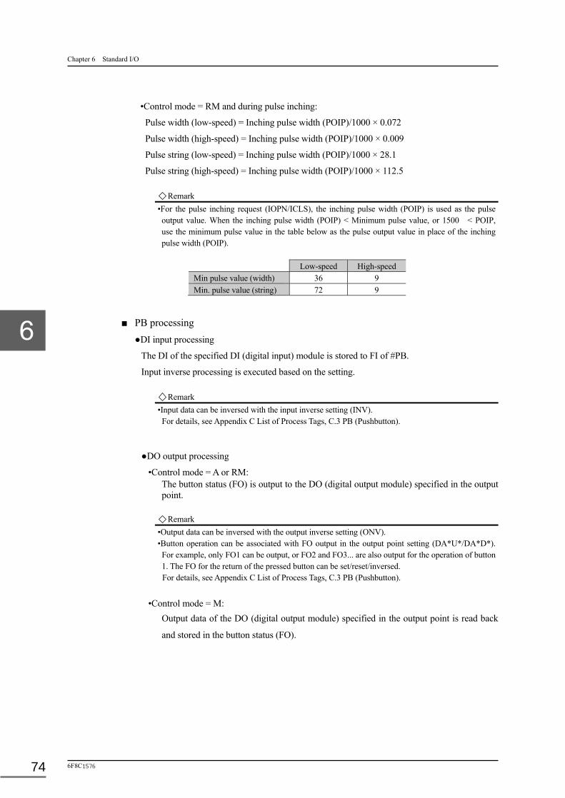
Chapter 6 Standard I/O
6F8C1576 74
•Control mode = RM and during pulse inching:
Pulse width (low-speed) = Inching pulse width (POIP)/1000 × 0.072
Pulse width (high-speed) = Inching pulse width (POIP)/1000 × 0.009
Pulse string (low-speed) = Inching pulse width (POIP)/1000 × 28.1
Pulse string (high-speed) = Inching pulse width (POIP)/1000 × 112.5 Remark
•For the pulse inching request (IOPN/ICLS), the inching pulse width (POIP) is used as the pulse output value. When the inching pulse width (POIP) < Minimum pulse value, or 1500 < POIP, use the minimum pulse value in the table below as the pulse output value in place of the inching pulse width (POIP).
Low-speed High-speed Min pulse value (width) 36 9 Min. pulse value (string) 72 9
■ PB processing
●DI input processing
The DI of the specified DI (digital input) module is stored to FI of #PB.
Input inverse processing is executed based on the setting.
Remark •Input data can be inversed with the input inverse setting (INV). For details, see Appendix C List of Process Tags, C.3 PB (Pushbutton).
●DO output processing
•Control mode = A or RM: The button status (FO) is output to the DO (digital output module) specified in the output point.
Remark •Output data can be inversed with the output inverse setting (ONV). •Button operation can be associated with FO output in the output point setting (DA*U*/DA*D*). For example, only FO1 can be output, or FO2 and FO3... are also output for the operation of button 1. The FO for the return of the pressed button can be set/reset/inversed. For details, see Appendix C List of Process Tags, C.3 PB (Pushbutton).
•Control mode = M:
Output data of the DO (digital output module) specified in the output point is read back
and stored in the button status (FO).

6.4 Details of Standard I/O Processing
Unified Controller nv series type2 light Functional Manual 75
■ TC processing
Timer (TIM) and counter (CNT) operations are done based on the tag type (TYPE) specification.
●Timer processing Turns on (ON) at the start instruction (STAT), and PV addition starts. Different values are added to PV based on the time unit (TMEU: second, minute, hour, day).
Second: + 1 per 1 sec Minute: + (1/60) per 1 sec Hour: + (1/3600) per 1 sec Day: + (1/86400) per 1 sec
PV addition stops at the stop instruction (STOP). PV=0 at the reset instruction (RST). Rollover processing is performed when PV exceeds the maximum value (MAX). Preset is achieved (UP) when preset value (SV) < PV.
Addition continues up to the maximum value even preset is achieved.
[Setting other than 0 < SV; UP is OFF.]
Figure 6-2 Timer operation (TC processing)
TMEU :時間単位[秒(0)、分(1)、時(2)、日(3)]MAX :最大値[0<MAX 設定]
PV :経過時間STAT :スタート指令RST :リセット指令ON :計時中
SV :プリセット値STOP :ストップ指令UP :プリセット値到達
MAX
SV
0
STAT
STOP
RST
UP
ON
(注)SV=0時、UPは OFF になります。
TMEU : Time unit [second (0), minute (1), hour (2), day (3)
MAX : Maximum value [0 < MAX setting]
PV : Elapsed time SV : Preset value
STAT : Start command STOP : Stop command
RST : Reset command UP : Preset value reached
ON : Counting
(NOTE) UP is OFF When SV=0.

Chapter 6 Standard I/O
6F8C1576 76
●Counter processing
PV increments (+1) at the increment instruction (INCR).
PV decrements (-1) at the decrement instruction (DECR).
Preset is achieved (UP) when preset value (SV) PV
[processing is executed only when 0 < SV]
Preset is achieved (DOWN) when PV SV [processing is executed only when SV < 0]
Rollover processing is performed when maximum value (MAX) < PV
Rollover processing is performed when PV < minimum value (MIN)
Reset to PV = 0 at the reset instruction (RST).
M IN : 最小値[ M IN< 0と設定する事]PV : 現在値SV : プリセット 値[ 0< SVと設定する事]INCR : インクリメ ント 指令RST : リセット 指令UP : プリセット 値到達( UP)
M IN : 最小値[ M IN< 0と設定する事]DECR : デクリメ ント 指令DOW N : プリセット 値到達( DOW N)
MAX
+SV
0
-SV
MIN
INCR
DECR
RST
UP
DOWN
PV
( 注) SV=0時、UP/ DOW Nは共にOFFになります。
Figure 6-3 Counter operation (TC processing)
MIN : Minimum value [Set MIN<0] MIN : Minimum value [Set MIN<0]
PV : Current value DECR : Decrement command
SV : Preset value [Set 0 <SV] DOWN : Preset value reached (DOWN)
INCR : Increment command
RST : Reset command
UP : Preset value reached(UP)
(NOTE) Both UP and DOWN are OFF when SV=0.

6.4 Details of Standard I/O Processing
Unified Controller nv series type2 light Functional Manual 77
■ T processing
●Timer processing
Timer processing has 2 types of timers; 0.1 sec timer and 0.1 min timer.
The first 256 of the timer variables (T[0] to T[255]) are 0.1 sec timers, and the latter 256
(T[256] to T[511]) are 0.1 min timers.
Current value (VAL) addition starts at the start instruction (STAT).
Different values are added to VAL based on the time unit (type of the first half or second
half).
0.1 sec: + 1 per 0.1 sec
0.1 min: + 1 per 0.1 min (6 sec)
VAL addition stops at the stop instruction (STOP).
VAL = 0 at the reset instruction (RST).
Limited to 32767 when the maximum value (32767) of the integer type is reached.
Time up (UP) occurs when setting value (SET) VAL.
Figure 6-4 Timer operation (T processing)
32767
SET
0
STAT
STOP
RST
UP
VAL : Present value SET : Setting value
STAT : Start command STOP : Stop command
RST : Reset command UP : Time up

Chapter 6 Standard I/O
6F8C1576 78
■ C processing
●Counter processing
Current value (VAL) increments (+1) at the increment instruction (INC).
Current value (VAL) decrements (-1) at the decrement instruction (DEC).
Count up (UP) when setting value (SET) VAL
Count down (DOWN) when - setting value (SET) VAL
Limited to 32767 when the maximum value (32767) of the integer type is reached.
Limited to -32768 when the minimum value (-32768) of the integer type is reached.
Reset to VAL= 0 at the reset instruction (RST).
Figure 6-5 Counter operation (C processing)
VA L : 現在値INC : インクリメ ント 指令UP : カウント アップ( UP)
SET : 設定値DEC : デクリメ ント 指令 RST:リセット 指令DOW N : カウント ダウン( DOW N)
32767
+SET
0
-SET
-32768
INC
DEC
RST
UP
DOWN
VAL
VAL : Present value SET : Setting value
INCR : Increment command DEC : Decrement command RST : Reset command
UP : Count up (UP) DOWN : Count down (DOWN)

6.5 Sequence Tag
Unified Controller nv series type2 light Functional Manual 79
6.5 Sequence Tag
The sequence tag (SEQ) is directly managed by the SFC instruction.
The result of the SFC instruction is stored in the tag, and based on the result, the phase progress
and congestion alarms are indicated on the OIS screen.
The progress of sequence (execution of the SFC instruction) can be manipulated with forced or
confirmed phase progress operation from the OIS screen.
6.6 Process Alarm
Process alarms are generated and reset for the registered PV (indicator), LP (controller), PB
(pushbutton), TC (timer/counter) and SEQ (sequence operating equipment) tags.
Process alarms for PV (indicator), LP (controller) and other tags have dead band to output the
result taking hysteresis into account. When the scan of PV (indicator) is turned off, the PV value
can be set from OIS-DS. During scan off, no sensor check is performed, so the sensor error
(PVI) is reset.
The following table shows the processing details.
Table 6-3 Process alarm processing details Tag instrument variable Process alarm details
Indicator variable (PV) PVD (PV change rate) Alarm PVL (PV lower limit) Alarm PVLL (PV lower-lower limit) Alarm PVH (PV upper limit) Alarm PVHH (PV upper-upper limit) Alarm PRE (PV processing error) Alarm PVIL (PV sensor lower limit error) Alarm PVIH (PV sensor upper limit error) Alarm PDE (Device error) Alarm UP (Integration value reached) Alarm TTE (Integration change rate) Alarm
Controller variable (LP) VPI (Valve opening error) Alarm PDV/NDV(positive/negative, deviation)) Alarm MVL (MV lower limit) Alarm MVH (MV upper limit) Alarm MVE (MV error) Alarm CLI (Control stop) Alarm
Pushbutton (PB) FI1~FI8 (FI alarm) Alarm IOE (DI/DO module error) Alarm ASA (Answerback) Alarm IL (Interlock) Alarm TT (Thermal trip) Alarm

Chapter 6 Standard I/O
6F8C1576 80
Timer/counter (TC) PRE (PV processing error) Alarm
UP (Upper limit reached) Alarm ON (Counting) Alarm DOWN (Lower limit reached) Alarm
Sequence (SEQ) STA (Stall) Alarm ASA (Answerback) Alarm ILA (Interlock) Alarm CNRQ (Confirmation request waiting) Alarm
Remark
・When a sensor error (PVIL/PVIH) is detected, the relevant PV data update is stopped, and the normal value in the previous cycle is retained. When the optional update during sensor error (PVIR) is specified, however, the ADC count (RAW) causing the sensor error is kept normalized and PV value is updated. The sensor upper limit or lower limit error does occur.
・The control stop alarm (CLI) for the controller should be generated and reset by the user application. ・The deviation error (PDV/NDV) is automatically reset in M/RM control mode. ・The MV upper limit (MVL) and MV lower limit (MVH) are updated regardless of the control mode. ・The following alarms are excluded from alarm suppress:
Indicator: PDE alarm Controller: MVE alarm Pushbutton: IOE alarm
・ The alarm detected by the controller is recorded in the alarm history of OIS-DS. The time of alarm in the alarm history is not the time of detection, but the time of entry in the alarm history. If a large number of alarms occur concurrently, alarms are divided into groups and the groups are entered in order, not at once. This makes the time of alarm generation slightly different.

81
Chapter 7 nV-Tool Support Function To define the operation of the Unified Controller nv series type2 light, the nv series nV-Tool is used
as an engineering environment.
The nV-Tool is a Windows application that runs on a PC, and is a common platform with the
engineering of the Integrated Controller V series.
7.1 Module Parameters ···························································· 82
7.1.1 Controller operation specification ·································· 82
7.1.2 Task execution specification ········································ 83
7.1.3 Duplex information and tracking ··································· 84
7.1.4 Status change indication ············································· 85
7.1.5 Other and Ethernet ··················································· 86
7.1.6 I/O loop ································································ 87
7.1.7 I/O node ······························································· 88
7.2 Execution Status Monitor ···················································· 89
7.2.1 Task run time measurement ········································· 89
7.2.2 Program monitor ····················································· 91
7.2.3 Data monitor ·························································· 91
7.3 Online Maintenance ··························································· 92
7.3.1 I/O live insertion/removal ··········································· 92
7.3.2 Scan cycle ····························································· 92
7.3.3 Program download ··················································· 92
7.3.4 Instruction word swap ··············································· 93
7.3.5 Contact and coil force ··············································· 93

Chapter 7 nV-Tool Support Function
6F8C1576 82
7.1 Module Parameters
The elements constituting the system are called modules. The setting items to define the
operation of the modules are called module parameters.
Module parameters include controller operation specification, task execution specification,
duplex information, tracking table, status change notice, Ethernet setting information and I/O
management information.
7.1.1 Controller operation specification
The following basic operations of the controller are specified as below.
Table 7-1 Controller operation setting
Item Description Value Program fallback When an error is detected during program execution,
move to ERROR mode, or disconnect error program and continue operation (fallback).
Y: Shutdown N: Fallback (default)
I/O fallback When an error is detected during batch I/O, operation move to ERROR mode, or stop error module and continue I/O (fallback).
Y: Shutdown N: Fallback (default)
Global variable initialization specification
Initialize (zero clear) the global variable when RUN is activated.
N: Not initialized (default) Y: Initialized
Local variable initialization specification
Initialize (zero clear) the local variable when RUN is activated.
N: Not initialized (default) Y: Initialized
Output of time setting by program to log
Enter the time adjustment from the program in the event log.
Y: Entered in log (default) N: Not entered in log
DC short interruption
Long interruption or short interruption. 0: Long interruption (default) 1 - 30 (sec): Short interruption
Remark ・The user variable (EA4) and station memory (EA13) are reset during the initialization of global variable. ・The tacking area (EA0) and non-tracking area (EA3) of the local variable are reset during the initialization of local variable. When initialization is not specified, the non-tracking area (EA3) is reset. For the initialization of variable, see Chapter 4 Variables, 4.2 Initialization of the Variable.

7.1 Module Parameters
Unified Controller nv series type2 light Functional Manual 83
7.1.2 Task execution specification
The execution conditions of the task are specified.
Table 7-2 Task execution setting
Item Description Value Priority 1 task type (EV)
Event task
No value
Priority 2 task type (IP)
Use of interrupt task. Stop: Not used (default) Run: Used
Priority 3 task type (HS)
Use of high-speed scan task. Stop: Not used (default) Run: Used
Set scan cycle at intervals of 1 ms. 0, 10 - 500 (ms) (Default value: 0)
Priority 4 task type (MS)
Use of the main scan task. Run: Used (fixed)
Set scan cycle at intervals of 10 ms. 100 - 10000 (ms) (Default value: 1000)
Note
●Scan cycle Both high-speed scan and main scan are executed at a certain interval. Even if the scan cycle is appropriate, the tasks are still running at the end of the scan cycle if the load is heavy. This is called the scan congestion, which is detected as a minor error. The longer run time of user programs or extended standard I/O processing including alarm generation for frequent status change due to external disturbance may the cause of scan congestion. (For details, see 3.4 Task Error Monitoring in Chapter 3.)
●Limitation of online change of scan cycle When the scan cycle specified in the online change is shorter than the practical value, scan congestion would take place and this may cause the controller to shut down due to failure. To prevent this, a reduction to more than 20% of the present value is inhibited. The minimum variation range is HS = 1 ms and MS = 10 ms.
●Sub-scheduling and grouping ・Sub-scheduling is to specify the execution cycle of a program in the main scan task as the integral multiple
of the main scan. ・Grouping is to specify the initial execution phase when sub-scheduling is specified in the main scan task
(default: 1). (For details, see 3.3.5 Sub-scheduling and grouping in Chapter 3.)

Chapter 7 nV-Tool Support Function
6F8C1576 84
7.1.3 Duplex information and tracking
Options for the duplex system operation when the controller is dualized.
Table 7-3 Duplex information setting
Item Description Value System alarm in duplex operation
Generate an alarm as minor error when standby system is switched to online system during duplex system configuration.
Normal: Minor error alarm (default) Special: No fault
Auto restart
Not used in type2 light.
Operation with I/O status inconsistency
Not used in type2 light.
Table 7-4 Tracking setting
Item Description Value Tracking (high-speed) Equalize data in online and standby systems
by synchronizing parameters with high-speed scan.
A maximum 64 parameters can be set.
Tracking (main) Equalize data in online and standby systems by synchronizing parameters with main scan.
A maximum 64 parameters can be set.

7.1 Module Parameters
Unified Controller nv series type2 light Functional Manual 85
7.1.4 Status change indication
Stats change indication is specified in the activation condition of the interrupt event task (IP). A
maximum of 32 points (word units) can be set.
Table 7-5 Status change indication setting
Item Description Value State change detection Detect status change. N (default)
Y Target I/O module Select I/O modules to detect status change. I/O module name I/O word No. Set word number to detect the I/O module status
change. Word number
Detection mask (when ON)
Set the bits of hex bit pattern data for ON detection . 1: Yes 0: No
Detection mask (when OFF)
Set the bits of hex bit pattern data for OFF detection. 1: Yes 0: No
IP task No. Set the IP task to be activated when ON/OFF is detected.
IP task number (0 - 7)
Remark ●I/O module to detect
Register the I/O module to detect in advance in the I/O node unit. ●Detection mask
Set 16-bit pattern data in hex for detection mask. (Example) For ON detection mask, setting (pattern data) of bits 0 to 3, bits 8 to 11, and bit 15 for ON
detection is shown below. 8F0F
To enable both ON and OFF detection, set 1 on both ON and OFF detection masks. ●I/O interrupt task (IP) information
The start state of the I/O interrupt task (IP) is confirmed in I/O interrupt task (IP) information (ZW236 - 259) of system variable (ZW). (See Appendix A.2 List of System Variables.)

Chapter 7 nV-Tool Support Function
6F8C1576 86
7.1.5 Other and Ethernet
Setting of OIS related information and IP address information of the Ethernet port for nV-Tool is
described below.
Table 7-6 Other and Ethernet setting
Item Description Value Computer link 1 - 4 Not available in type2 light. Difference between GMT and local time
Set difference between Greenwich mean time and local time in hours. Set “+9” for Japan.
+13 - -13 (Default value: +9)
Correction unit system Select the unit system of the temperature/pressure correction of the PV tag.
SI (default) US customary unit
OIS tag write scan synchronization
Write tag data from OIS in synchronization with the main scan.
N: Asynchronous (default) Y: Synchronous
M mode DO read-back Read back the button status (FO) output of the PB tag in M mode.
Y: (default) N
Alarm (MVL, MVH, UP) condition
Set criteria for MV upper/lower limit alarms (MV>, MVH) and integration setting value reached (UP) as follows; ><: MVL = MLA > MV value, MVH = MHA < MV value
UP = PSET < PV value ≥≤: MVL = MLA ≥ MV value, MVH = MHA ≤ MV value
UP = PSET ≤ PV value
>< (default) ≥≤
Controller number Set a unique controller number for each controller for monitoring in CIEMAC-DS system.
1 - 64 (Default value: 0)
DS scan Permit real-time trend data collection. Permit (default) Inhibit
Inter-controller transmission Permit inter-controller transmission. Permit (default) Inhibit
IP address type Not used for type2 light Class B type (default)
IP address primary Set the IP address of the primary system. Any value (see Table 7-7 IP address setting for nV-Tool. Subnet mask primary Set the negative mask of the primary system.
IP address secondary Set the IP address of the secondary system. Subnet mask secondary Set the sub-net mask of the secondary system.
Remark
●Correction unit system The correction unit system is used for the temperature/pressure correction in the PV tag. ・SI (International System of Units): °C for temperature, Pa for pressure (absolute temperature = 273.15(°C), 1 atmosphere = 101.3 (KPa)
・U.S. customary unit: °F for temperature, PSI for pressure (absolute temperature = 459.57 (°F), 1 atmosphere = 14.7 (PSI)
●Controller number The OIS is capable of monitoring 32 nodes. Set the controller number associated with the node number (1 - 32). Set “0” to disable monitoring. The controller number must be unique.
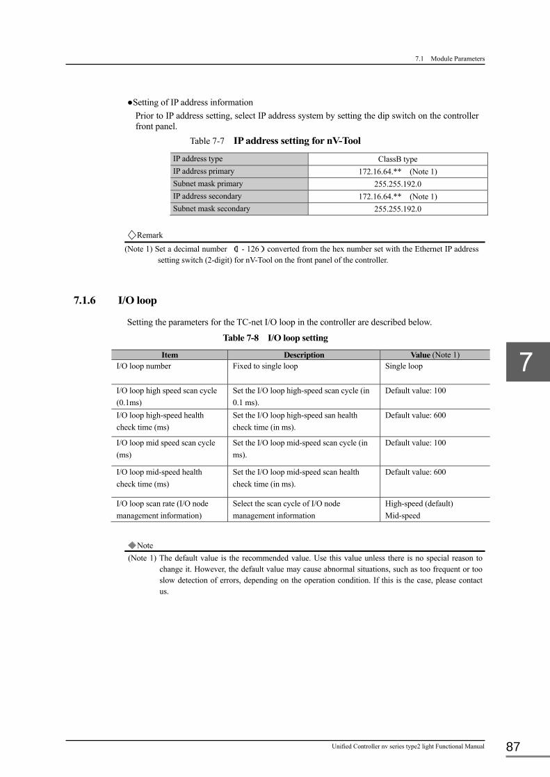
7.1 Module Parameters
Unified Controller nv series type2 light Functional Manual 87
●Setting of IP address information Prior to IP address setting, select IP address system by setting the dip switch on the controller front panel.
Table 7-7 IP address setting for nV-Tool
IP address type ClassB type IP address primary 172.16.64.** (Note 1) Subnet mask primary 255.255.192.0 IP address secondary 172.16.64.** (Note 1) Subnet mask secondary 255.255.192.0
Remark
(Note 1) Set a decimal number (1 - 126) converted from the hex number set with the Ethernet IP address setting switch (2-digit) for nV-Tool on the front panel of the controller.
7.1.6 I/O loop
Setting the parameters for the TC-net I/O loop in the controller are described below.
Table 7-8 I/O loop setting
Item Description Value (Note 1) I/O loop number Fixed to single loop
Single loop
I/O loop high speed scan cycle (0.1ms)
Set the I/O loop high-speed scan cycle (in 0.1 ms).
Default value: 100
I/O loop high-speed health check time (ms)
Set the I/O loop high-speed san health check time (in ms).
Default value: 600
I/O loop mid speed scan cycle (ms)
Set the I/O loop mid-speed scan cycle (in ms).
Default value: 100
I/O loop mid-speed health check time (ms)
Set the I/O loop mid-speed scan health check time (in ms).
Default value: 600
I/O loop scan rate (I/O node management information)
Select the scan cycle of I/O node management information
High-speed (default) Mid-speed
Note
(Note 1) The default value is the recommended value. Use this value unless there is no special reason to change it. However, the default value may cause abnormal situations, such as too frequent or too slow detection of errors, depending on the operation condition. If this is the case, please contact us.

Chapter 7 nV-Tool Support Function
6F8C1576 88
7.1.7 I/O node
Setting information on the node connecting to the TC-net I/O loop of the controller is described
below.
Table 7-9 I/O node setting Item Description Value
I/O fallback Select I/O fallback. Y (Default) N
I/O bus healthy check time (ms)
Set the healthy check time of I/O bus. (in ms)
Default value: 800 (Note 1)
Note
(Note 1) Use the default value unless there is no special reason to change the value. However, the default value may cause abnormal situations, such as too frequent or too slow
detection of errors, depending on the operation condition. If this is the case, please contact us.
Remark ● When “output continuation during error = N” in health check cycle setting, be sure to set as indicated
below. Otherwise, output from the I/O module may be reset when switching of PUM21 or SA9** in duplex system takes place. When “output continuation during error = Y,” the principle is not applied.
・Principle of setting
Controller switching time in duplex system < I/O loop mid-speed scan health check time < I/O bus health check time
・Recommended values I/O loop mid-speed scan health check time = 600 ms I/O bus health check time = 800 ms

7.2 Execution Status Monitor
Unified Controller nv series type2 light Functional Manual 89
7.2 Execution Status Monitor
The type2 light controller has three monitoring functions for checking task execution status.
7.2.1 Task run time measurement
The type2 light controller is capable of measuring the task run time and indicating it on the
nV-Tool screen.
The run times listed below are indicated in the high-speed scan (HS) and main scan (MS).
Table 7-10 Run time indication in high-speed/main scan
Time Measurement range Indication
Scan time
(at 0.01 msec cycle)
Task run time and idle time Present value, minimum,
maximum
Task execution time
(at 0.01 msec cycle)
Bath I/O, standard I/O, and user program Present value, minimum,
maximum

Chapter 7 nV-Tool Support Function
6F8C1576 90
The run time measurement in the high-speed scan and main scan is illustrated in the figure
below.
Figure 7-1 Run time measurement
Note
・Set the scan cycle time when the free time is in about 20% of the scan times to secure stable operation by checking the time required for all tasks, and individual scan times.
・The run time of interrupt task (①) is not included in the free time of the main scan. Include the run time of interrupt task to calculate the free time to find the accurate free time of the main scan.
Free time of the main scan = (MS task) Scan time - ( (MS task) Task run time + (MS task) Duplex tracking processing time ) - ( (HS task) Task run time + (HS task) Duplex tracking processing time
× The number of times of HS scan carried out before (MS task) Scan time ) ・The suspended time (②) is not included in the task run time.
(MS task) Task run time = (MS task) Task run time(1) + (MS task) Task run time(2)
Batch input
Main scan
(MS task) Task run time(1)
(MS task) Scan time
User program HS scan
(HS task) Task run time
(HS task) Scan time
(Suspended)②
Batch input
Stand input
Stand input
Stand output
Batch output
User program
Stand output
Batch output User program
HS scan
①
Susp
ende
d
Free time
Free time
(MS task) Task run time(2)

7.2 Execution Status Monitor
Unified Controller nv series type2 light Functional Manual 91
7.2.2 Program monitor
The program monitor is capable of display the real-time execution status of a program (live circuit, data display) in the range displayed on the program edit screen.
The program source for display used in the program monitor is stored in nV-Tool, not in the controller. The execution file (object) downloaded from nV-Tool to the controller is binary data from which the program source cannot be created.
Simultaneous display of up to four screens can be requested to nV-Tool for each controller. Up
to four nV-Tools can make a display request to the program monitor for each controller.
Figure 7-2 Connection of program monitors and nV-Tools
7.2.3 Data monitor
Program monitor screen of nV-Tool the statuses of devices and registers up to 32 points at
maximum and displays them on the screen.
type2 light controller
nV-Tool(1)
Program monitor
nV-Tool(2)
Program monitor
nV-Tool(3)
Program monitor
nV-Tool(4)
Program monitor

Chapter 7 nV-Tool Support Function
6F8C1576 92
7.3 Online Maintenance
The information of the program, execution conditions, and hardware registration state can be
changed while the program is being executed. This is called online maintenance, indicating
changes made online.
7.3.1 I/O live insertion/removal
If a unit failure of the I/O module occurs during operation, the failing module can be replaced while the system operation is continued and the program is being executed.
The TC-net I/O module is connected via serial bus, so the module can be installed or removed
without affecting other I/O modules.
7.3.2 Scan cycle
The execution cycle of the high-speed scan task and main scan task can be changed any time.
It is reflected from the next cycle after the change.
7.3.3 Program download
Each task or function block can be changed or downloaded by task or by function block (by
POU) any time including during execution.
■ Specification of download file
When the program is changed with the program editor of the nV-Tool, the target of download
can be restricted.
• Not download the files already downloaded
The download targets are only the files changed. This restriction shortens the download time.
• Download the files already downloaded
The download targets are all files within the task.
■ Specification of program continuous operation
After the program is changed and downloaded during execution, it can be specified whether to
continue the execution state immediately before, or restart after initialization.
• Continue to use local variables and execute
After download, execution is restarted after copying the current values of the local variables
within the task. The execution state is continued.
• Initialize local variables and execute
After download, all the local variables within the task are cleared to zero before execution.
The execution state is initialized, but the global variables are not initialized.

7.3 Online Maintenance
Unified Controller nv series type2 light Functional Manual 93
7.3.4 Instruction word swap
This is a function to change the program by instruction word during execution. Replacement of instruction words, input of instruction words, and rewrite of parameter values can be done.
Individual instruction words of the program can be replaced with other instruction words that are equivalent. This is called an instruction word swap. This does not mean replacing them with totally unrelated commands.
If the inputs/parameters are not variables and direct values (immediate values), the value themselves can be rewritten to other values. This is called an immediate swap.
The variable names specified in the inputs/parameters can be rewritten to other variables. This is called a variable swap.
Following instructions can be used for swap.
Table 7-11 Swappable commands
Swappable command
Swap type Instruction word Immediate value Variable
Contact A-contact, B-contact - Available Coil Coil, reverse coil, set coil,
reset coil - Available
Gate A-contact gate B-contact gate
- Available
Load
Available Available
Store/Set - Available
7.3.5 Contact and coil force
The contact coil force is to hold contact input and coil output by force during program execution.
Any contact input or coil output instruction can be issued using the program editor of nV-Tool
with “force” option.
94
Chapter 8 RAS Function The RAS stands for Reliability, Availability and Serviceability. The nv series unified controllers
increase the reliability and serviceability and support the operation of the controller-based systems.
This capability is generally called the RAS function.
8.1 Hardware Diagnosis ··························································· 96
8.1.1 Power-on diagnosis ·················································· 96
8.1.2 Regular diagnosis ···················································· 96
8.1.3 Runtime diagnosis ··················································· 96
8.2 Software Diagnosis ····························································· 97
8.2.1 Program structure monitoring ······································ 97
8.2.2 Execution time monitoring ·········································· 97
8.3 System Tags ····································································· 98
8.3.1 Error information ····················································· 98
8.3.2 System information ·················································· 98
8.4 System Logs ····································································· 99
8.4.1 Error log ······························································· 99
8.4.2 Event log ······························································ 99
8.4.3 Transmission log ····················································· 99
8.4.4 Intervention log ······················································· 99
8.4.5 Notes on system logs ·············································· 100
8.5 System logs of transmission part ·········································· 100
8.6 Troubleshooting ······························································ 101

8.1 Hardware Diagnosis
Unified Controller nv series type2 light Functional Manual 95
8.6.1 Occurrence of errors ··············································· 101
8.6.2 LED error indicators on the front panel ························· 101
8.7 List of Diagnosis Items ······················································ 102

Chapter 8 RAS Function
6F8C1576 96
8.1 Hardware Diagnosis
The hardware elements of the controller is subject to the diagnosis.
The diagnosis can be classified according to when, what and how . The basic policy of diagnosis
is described in this section.
8.1.1 Power-on diagnosis
The initialization status is checked when the power of the controller is turned on. The following
risk factors are taken into account in this diagnosis:
• Potential effect of electrical impact of power-on due to unexpected blackout.
• Potential effect to memory backup due to low voltage of batteries.
When the result of diagnosis shows hardware failure or loss of memory, control is not resumed
in principle.
8.1.2 Regular diagnosis
The system components are monitored for failure during operation. Because of the difficulty to
handle all components simultaneously, and minimization of reduction in controller efficiency
due to slowed-down operation, the regular diagnosis is performed.
When an error is detected, the error and required retry conducted are informed to the active
system, and if it is major failure, operation is suspended and the current active system is
switched.
The regular diagnosis includes the verification of diagnostic result through the reference of the
self-diagnosis result of each component (a module equipped with the system bus).
8.1.3 Runtime diagnosis
The diagnosis is conducted as part of the inherent operation of the controller, at runtime.
・ In the batch I/O, input/output data and input/output status are diagnosed during processing in
reference to the self-diagnosis information of each I/O module.
・ In the tracking processing that equalizes the memory of the standby system in the duplex
system, the validity of the transfer information and transfer mechanism are diagnosed with the
diagnosis information attached to the memory data to be transferred.
・ The controller memory has the ECC function to diagnose the validity of memory, every time
the memory is accessed.

8.2 Software Diagnosis
Unified Controller nv series type2 light Functional Manual 97
8.2 Software Diagnosis
For the programs such as the main scan task, syntax diagnosis has been completed when it is
created and compiled with the nV-Tool. This means the static validity of these programs is
guaranteed. However, elements such as dynamic validity or interference with other programs are
not ensured until actual operation in the runtime environment proves them.
Software diagnosis checks the validity of program in runtime environment.
8.2.1 Program structure monitoring
The program and POU structure constituting the task can be monitored by executing the task.
The structure of the program is generally diagnosed by the editor and compiler of the nV-Tool in
advance, and a program containing an error or inconsistency is not cannot be downloaded.
However, a boundary error, nesting error, or stack error may be detected only when the program
is running. Sufficient care should be taken for the details of the program.
If an error is found in a specific task, the task is aborted in the task fallback processing.
8.2.2 Execution time monitoring
The HS and MS tasks executed at fixed cycles are assumed to be completed at the specified scan
cycle. If they are not completed within the scan cycle, "scan congestion" is assumed.
Scan congestion may occur due to the startup of an event task caused by an external factor or a
variation of task execution time, but that alone does not cause a major failure.
If the scan task does not complete within three times the scan cycle, a major failure occurs and
the system shuts down.
One of the possible causes for continued scan congestion is that the load of individual scan tasks
is always heavy or increased by external factors. To prevent this situation, the scan cycle should
be set with a sufficient margin.

Chapter 8 RAS Function
6F8C1576 98
8.3 System Tags
8.3.1 Error information
A system tag is information that indicates whether the status of the controller and related
hardware is normal or abnormal. This includes the system and device alarms.
What the RAS function detects is set on the system tag.
The system tag status and status change are transferred to the OIS-DS, which displays the
received information on relevant screens. The alarm and controller status can be manipulated
from the OIS-DS by writing the atom of individual system tags.
Error information includes the following:
• Duplex status (in backup, in single system operation)
• Ethernet transmission status (FN812 operation status, node status)
• TC-net IO transmission status (ring status, bus status, duplex status)
• SIO operation status (operation mode, duplex status)
• IO operation status (IO module status)
Remark • The alarm detected in the controller is recorded in the OIS-DS alarm history. The time of alarm in the
alarm history is not the time of detection, but the time of entry in the alarm history.
• If a large number of alarms occur concurrently, alarms are divided into groups and the groups are entered in order, not at once. This makes the time of entry slightly different.
8.3.2 System information
The system tag does not necessarily indicates an alarm, but also presents system status
information.
The status information indicated in the system tag includes the following:
• Controller configuration (module and I/O structure)
• Operation mode (control, suspended, equalization)
• Entry and operation of user programs
• Version information (a list of firmware and hardware versions)

8.4 System Logs
Unified Controller nv series type2 light Functional Manual 99
8.4 System Logs
The controller operation status change, commands to the controller via Ethernet, and errors
detected in self-diagnosis are entered in the system log with the date and time.
Even if the system appears to operate normally, an unexpected problem arises and the system
may be put into a serious status. To prepare for emergencies, the system log must be read
regularly.
8.4.1 Error log
• Errors detected in self diagnosis are entered.
• These errors are classified as the major failure, minor failure and caution.
• The major failure contains the information important for analysis, i.e., the cause of duplex
system switching and error down.
• The minor failure and caution do not seriously affect the controller operation at the time of
occurrence, but potentially suggest the effect of a serious problem, or affect.
8.4.2 Event log
• The controller operation status change is recorded in this log.
• This includes the information such as power off, program download, clock setting change,
and duplex system switching.
• The log contains important information on the duplex system such as comparison of events in
the online and standby systems which may be used for estimating the operation of these
systems and diagnostic results.
8.4.3 Transmission log
• The network operation status is recorded.
• While the indication on the OIS-DS appears normal and the controller does not generate an
error, the log may contain important information on the network operation status, such as
frequent retry for recovery in only the Ethernet transmission system.
8.4.4 Intervention log
• Input in the controller tag from the OIS-DS is recorded.
• The object of processing and settings, such as the tags listed in the OIS-DS Point screen for
remote operation, are recorded.
• Aside from operation from the OIS-DS, any operation via the network is recorded.

Chapter 8 RAS Function
6F8C1576 100
8.4.5 Notes on system logs
The system logs have limitations in the number of records.
Each time the latest data is recorded, the oldest one is erased. When a large number of events
(e.g. status change, occurrence of error and recovery, operation from the nV-Tool and HMI) take
place concurrently, the record of important information may be erased. To prevent this, the logs
must be checked regularly not to overlook the important information.
8.5 System logs of transmission part
The controller module PUM21 stores the system logs of controller parts (CPU) and transmission
part (FN). The information related to the interface between the controller parts and the
transmission parts is recorded in the transmission log of PUM21, but detailed information
including operation record of the transmission, and operation records of the transmission circuit
board is recorded in the system logs.
It may be effective to collect the transmission part log together with the controller log for
analysis and review. It should be noted to make sure of collecting both the transmission part log
and controller parts logs.
To display the system logs of transmission part (FN), select (FN) of the main slot No.1 in the
system review and click “System Log”.

8.6 Troubleshooting
Unified Controller nv series type2 light Functional Manual 101
8.6 Troubleshooting
8.6.1 Occurrence of errors
When the controller finds an error in self diagnosis, the error message (and related information)
is entered in the error log table. If the error inhibits the continuation of operation, all outputs are
turned off and the operation is aborted (system shutdown).
The 128 latest error messages and time of occurrence are retained in the error log table. The
information can be displayed on the nV-Tool.
In addition to errors logs, the following logs are also entered in the log table and can be
displayed on the nV-Tool:
• Event log: Power on/off, mode control
• Transmission log: Transmission of Ethernet, etc.
The connection and operation status of the modules entered by the nV-Tool (e.g. controller,
system bus modules, I/O modules) can also be checked.
Remark • See 5.4 Continuation and Suspension of I/O Module Operation, for the output and shutdown status during the error down.
8.6.2 LED error indicators on the front panel
When an error occurs in the controller, the RUN/ERR LED indicators on the front panel of the
controller operates as shown in Table 8-1 below. This means the details of error can be
understood with the LED indicator. The action to be taken for each type of error is also shown in
the table.
Table 8-1 LED indicators and location of errors
RUN/ERR indicator Error Action
RUN and ERR blink every time CPU operation Replace the CPU module if the error status does not disappear after restarting the controller. Repeated cycles of ERR blinks once -
RUN and ERR blink once Boot area
Repeated cycles of ERR blinks twice - RUN and ERR blink once
OS program RAM
Repeated cycles of ERR blinks 3 times - RUN and ERR blink once
OS working RAM
Repeated cycles of ERR blinks 4 times - RUN and ERR blink once
FROM ID
Repeated cycles of ERR blinks 5 times - RUN and ERR blink once
OS program BCC
ERR illuminates Error down Check the details of error with nV-Tool.

Chapter 8 R
AS Function
102
6F8C1576
8.7 List of Diagnosis Items
■ Power-on diagnosis (initialization)
Table below shows the diagnosis items and error log information during power-on diagnosis (initialization). The error information is described by the event number (hex), content, cause and action.
Table 8-2 Power-on (initialization) diagnosis items (1/4)
Diagnosis item Examination Operation after error detection
Error log information
Event No. Description Cause Action
Communication controller
Normal initialization of the communication controller
Error is logged, and error mode is started
0000 Communication controller error
Hardware failure Normal value of serial mode register = 0
Replace the CPU module and restart the system; or contact Toshiba service department.
Timer controller Normal initialization of the timer controller
0001 Timer controller error Hardware failure
Station bus memory Initialization of the station bus (read-back check)
0010 Station bus memory error Hardware failure
Memory data Loss of memory data 0102 Data loss check error The program is not downloaded; or the battery is not mounted.
Load system data including programs from nV-Tool, restart the system.
Program memory BCC Validity of the user program 0105 User memory BCC check error RAM memory failure Replace the CPU module and restart the system; or contact Toshiba service department.

8.7 List of D
iagnosis Items
103
U
nified Controller nv series type2 light Functional M
anual
Table 8-2 Power-on (initialization) diagnosis items (2/4)
Diagnosis item Examination Operation after error detection
Error log information
Event No. Description Cause Action
Memory Read/write of memory areas Error is logged, and error mode is started
0106 Memory check error (user program execution) RAM memory failure Replace the CPU module and restart the system; or contact Toshiba service department. 0107 Memory check error (user data reference)
0126 Memory check error (user program backup)
0127 Memory check error (user data backup)
012A Memory check error (selector internal SRAM)
012B Memory check error (selector I/O status change information)
012D Memory check error (tracking I/F external RAM)
012E Memory check error (tracking I/F internal RAM)
012F Memory check error (I/O loop memory A)
Remark
• Read/write of the following memory areas: User program area, user data area, user program backup area, user data backup area, internal RAM area, internal micro area, internal SRAM area, I/O information area, system bus area, tracking I/F area (internal/external), I/O loop memory area (A/B)

Chapter 8 R
AS Function
104
6F8C1576
Table 8-2 Power-on (initialization) diagnosis items (3/4)
Diagnosis item Examination Operation after error detection
Error log information
Event No. Description Cause Action
ECC circuit Validity of ECC circuit in each memory area
Error is logged, and error mode is started
0015 ECC circuit check error (user program execution) ECC circuit failure Replace the CPU module and restart the system; or contact Toshiba service department.
0016 ECC circuit check error (user data reference) 0017 ECC circuit check error (user program backup) 0018 ECC circuit check error (user data backup) 001B ECC circuit check error (selector internal SRAM) 001C ECC circuit check error (selector I/O status change
information) 001E ECC circuit check error (tracking I/F external RAM) 001F ECC circuit check error (Tracking I/F internal RAM)
Remark
• The memory areas below are equipped with an ECC circuit. Read/write check is done for each memory area. User program area, user data area, user program backup area, user data backup area, internal RAM area, I/O information area, tracking I/F area (internal/external), and I/O loop memory area (A/B)

8.7 List of D
iagnosis Items
105
U
nified Controller nv series type2 light Functional M
anual
Table 8-2 Power-on (initialization) diagnosis items (4/4)
Diagnosis item Examination Operation after error detection
Error log information
Event No. Description Cause Action Battery voltage CPU module battery voltage Minor failure is
logged, and operation is continued.
0E00 Detection of low battery level (CPU)
Low battery (voltage drop) Replace the battery.
Battery mounting CPU module battery mounting status
0E0C Battery not mounted (CPU) Battery not mounted。 Mount the battery properly.
Calendar Validity of data (date and time)read from the calendar LSI
0E0B Calendar error Calendar data error Replace the CPU module and restart the system; or contact Toshiba service department.
Power supply module
Operation of the power supply module
0E0E Power supply module error Power supply module error Replace the power supply, and restart the system; or contact Toshiba service department.

Chapter 8 R
AS Function
106
6F8C1576
■ Runtime (RUN) diagnosis
Table below shows the diagnosis items and error log information during runtime diagnosis (RUN). The error information is described by the event number (hex), content, cause and action.
Table 8-3 Runtime diagnosis items (RUN) (1/2)
Diagnosis item Examination Operation after
error detection
Error log information
Event No.
Description Cause Action
Basic unit configuration
Configuration of the modules mounted on the basic unit which must be the same with the configuration registered in nV-Tool.
Error is logged, and error mode is started
1000 Basic unit configuration registration error
Improper basic unit configuration registration Type 0: cross-check error, 1: no response, 2: not mounted
Match the registered and actual basic unit configurations.
Scan cycle setting Range of scan cycles of HS/MS
1005 Scan cycle setting error Improper scan cycle registration or memory corruption
Check the scan cycle setting value and if it is proper, load system data including programs from nV-Tool, and restart the system; or contact Toshiba service department.
Module parameters Setting of module parameters
100B Module parameter error Logical table (module parameters) error Offsets 18: priority 1, 1E: priority 2, 24: priority 3, 2A: priority 4
Correct the logical table (module parameters) with nV-Tool, and reload it.
Instance table Proper installation of the instance table
1010 Instance table logical error Corruption of setting information, or RAM memory failure Task types 0: EV, 2: IP, 3: HS, 4: MS
Clear the memory and download setting information from nV-Tool. If the same error still persists, contact Toshiba service department.
MS task run/stop setting
Setting of MS task to “run” 101B MS task setting error Wrong setting of the MS task Set “run” for the MS task, and reload setting information from nV-Tool.
User program Validity of user program registration information
1100 User program error Logical error in the program If no program is registered for the task, register the program and reload the task; or if a program is registered for the task, load the program from nV-Tool, and restart the system.

8.7 List of D
iagnosis Items
107
U
nified Controller nv series type2 light Functional M
anual
Table 8-3 Runtime diagnosis items (RUN) (2/2)
Diagnosis item Examination Operation after error detection
Error log information
Event No.
Description Cause Action
I/O scan cycle/talker block setting
Proper setting of I/O scan cycle/talker block
Error is logged, and error mode is started
101C I/O scan cycle/talker block setting error
Improper I/O scan cycle/talker block setting; or I/O gate array/I/O memory failure Settings 1: I/O scan cycle, 2: high-speed scan talker block, 3: medium-speed scan talker block, 4: scan stop/setting/start Errors 1: setting request error, 2: setting block count error, 3: setting value error, 4: request completion timeout
Check the setting value of I/O scan cycle/talker block. If there is no problem, load system data including programs from nV-Tool, and restart the system; or contact Toshiba service department.
I/O node I/O node down Error is logged and operation is continued.
0619 I/O node down I/O loop cable connection failure or SIO module failure, etc. Loop numbers 0: built-in Error SIO bit map Bits 15: node 18 to bit0: node 3
Check cable connection. If there is no problem, contact Toshiba service department.
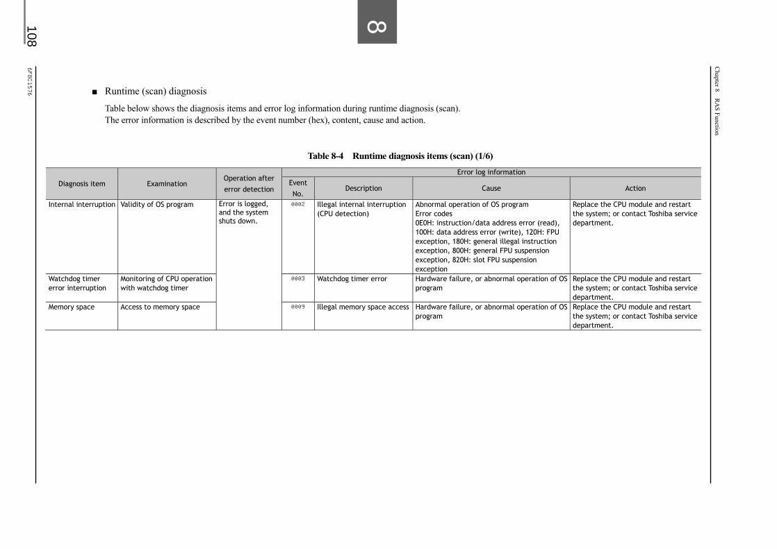
Chapter 8 R
AS Function
108
6F8C1576
■ Runtime (scan) diagnosis
Table below shows the diagnosis items and error log information during runtime diagnosis (scan). The error information is described by the event number (hex), content, cause and action.
Table 8-4 Runtime diagnosis items (scan) (1/6)
Diagnosis item Examination Operation after error detection
Error log information
Event No.
Description Cause Action
Internal interruption Validity of OS program Error is logged, and the system shuts down.
0002 Illegal internal interruption (CPU detection)
Abnormal operation of OS program Error codes 0E0H: instruction/data address error (read), 100H: data address error (write), 120H: FPU exception, 180H: general illegal instruction exception, 800H: general FPU suspension exception, 820H: slot FPU suspension exception
Replace the CPU module and restart the system; or contact Toshiba service department.
Watchdog timer error interruption
Monitoring of CPU operation with watchdog timer
0003 Watchdog timer error Hardware failure, or abnormal operation of OS program
Replace the CPU module and restart the system; or contact Toshiba service department.
Memory space Access to memory space 0009 Illegal memory space access Hardware failure, or abnormal operation of OS program
Replace the CPU module and restart the system; or contact Toshiba service department.

8.7 List of D
iagnosis Items
109
U
nified Controller nv series type2 light Functional M
anual
Table 8-4 Runtime diagnosis items (scan) (2/6)
Diagnosis item Examination Operation after error detection
Error log information
Event No.
Description Cause Action
ECC uncollectable error
Occurrence of ECC uncollectable error in memory areas
Error is logged, and the system shuts down.
010A ECC uncollectable error (I/O loop memory A) Memory or ECC circuit failure
Replace the CPU module and restart the system; or contact Toshiba service department.
010C ECC uncollectable error (user program execution) 010D ECC uncollectable error (user data reference) 0111 ECC uncollectable error (selector circuit) 0112 ECC uncollectable error (tracking I/F internal RAM) 0113 ECC uncollectable error (tacking I/F external RAM) 0114 ECC uncollectable error (shared memory)
0115 ECC uncollectable error (SDRAM)
Remark
•The ECC circuit is equipped with the following memory areas: User program area, user data area, user data backup area, internal SRAM area, I/O information area, tracking I/F area (internal/external), I/O loop memory area

Chapter 8 R
AS Function
110
6F8C1576
Table 8-4 Runtime diagnosis items (scan) (3/6)
Diagnosis item Examination Operation after error detection
Error log information
Event No. Description Cause Action
Device access Occurrence of error during access to a memory area
Error is logged, and the system shuts down.
0120 Device access error (common memory) Memory failure Replace the CPU module and restart the system; or contact Toshiba service department.
0121 Device access error (selector) 0123 Device access error (peripheral I/F)
Access timeout Occurrence of timeout during access to tracking I/F
0122 Access timeout (tracking I/F) Memory failure Replace the CPU module and restart the system; or contact Toshiba service department.
Task entry Availability of task entry area
Caution is logged, and operation is continued.
110D Task entry setting error The whole program area is used and the task entry area cannot be secured. RIO task entry setting error detected during batch/divided download of user program (configuration). MS task entry setting error detected during batch/divided download of user program (program). Task type 4: MS
Check the program capacity. Delete unnecessary programs and download user program again.
I/O scan start/stop request
Validity of I/O scan start/stop request in the beginning of I/O scan
Error is logged, and the system shuts down.
060E An error in I/O scan start and I/O release request at the start of RUN, or I/O scan stop and I/O clear request at the end of RUN
I/O loop interface failure I/O scan and clear 1: start, 2: stop, 3: clear, 4: release. Loop 0: loop A, 3: TC-net
Replace the CPU module and restart the system; or contact Toshiba service department.
Transmission circuit board
Validity of transmission circuit board
Minor failure is logged, and operation is continued.
0C32 Transmission circuit board error Transmission circuit board, CPU board or base unit failure.
Check the transmission module registration and mounting status. If there is no problem, replace the transmission module, and restart the system; or contact Toshiba service department.
TC-net scan block Healthiness of TC-net scan block during batch I/O
1009 Unhealthy TC-net scan block detected during batch I/O
TC-net transmission path error Check the TC-net transmission path; or running status of TC-net network controller.

8.7 List of D
iagnosis Items
111
U
nified Controller nv series type2 light Functional M
anual
Table 8-4 Runtime diagnosis items (scan) (4/6)
Diagnosis item Examination Operation after error detection
Error log information
Event No.
Description Cause Action
Instruction Validity of instructions Error is logged and the system shuts down; or operation is continued with program fallback. (Note 1)
1101 Illegal instruction detected during user task
User task or memory failure Correct the user task and reload it.
Program boundary Program execution area 1102 The user task runs past the program execution area.
Unregistered POU (program/ function/function block)
Download the POU (program/ function/function block).
Data boundary Data reference area 1103 The user program runs past the data reference area.
Out of reference memory Correct index modifier in the user program.
Word division stack pointer
Overflow/underflow of the word division stack pointer
1112 Detection of overflow/underflow of the word division stack pointer
Stack I/O count exceeding the limit Correct the user task and reload it.
Word joint stack pointer
Overflow/underflow of the word joint stack pointer
1113 Detection of overflow/underflow of the word joint stack pointer
Stack I/O count exceeding the limit Correct the user task and reload it.
Unsupported instruction
Presence of unsupported instruction
110F Detection of unsupported instruction during user task
User task or memory failure Correct the user task and reload it.
POU nest Validity of POU call 1111 POU call exceeding 6 nesting levels
Out of range of POU call nesting Change the nesting level of the POU call to 6 or less.
Micro stack Over or empty micro stack 0022 Micro stack error LP failure Replace the CPU module and restart the system; or contact Toshiba service department.
POU Presence of unregistered POU
101E Detection of unregistered POU Unregistered POU Conduct batch compilation with nV-Tool, and then batch download.
Direct I/O Occurrence of errors other than timeout of the station module during direct I/O
000C Detection of errors in the direct I/O PCI, etc.
Hardware failure Replace the CPU module and restart the system; or contact Toshiba service department.
Remark
(Note 1) System shutdown or continuation of operation with program fallback can be selected by setting module parameters. See 7.1.1 Controller operation specification for details of module parameter setting.

Chapter 8 R
AS Function
112
6F8C1576
Table 8-4 Runtime diagnosis items (scan) (5/6)
Diagnosis item Examination Operation after error detection
Error log information
Event No.
Description Cause Action
Scan congestion Scan task execution within the scan cycle
Minor failure is logged, and operation is continued.
1105 Detection of high-speed scan task congestion
High-speed scan task execution exceeding the scan cycle.
Increase the high-speed scan cycle, or decrease programs for the high-speed scan task.
1106 Detection of main scan task congestion Main scan task execution exceeding the scan cycle.
Increase the main scan cycle, or decrease programs for the man scan task.
Program scan time over
User program execution time
Error is logged, and the system shuts down.
110D High-speed scan task execution exceeding time limit (control value = High-speed scan cycle setting value x 5)
The scan time exceeding the default value.
Decrease the number of programs. If the error still persists, check the LP failure.
110E Main scan task execution exceeding time limit (control value = High-speed scan cycle setting value x 5)
The scan time exceeding the default value.
Decrease the number of programs. If the error still persists, check the LP failure.
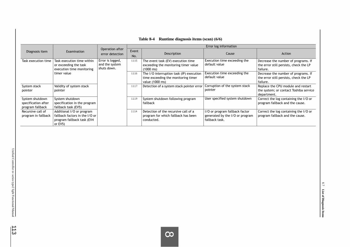
8.7 List of D
iagnosis Items
113
U
nified Controller nv series type2 light Functional M
anual
Table 8-4 Runtime diagnosis items (scan) (6/6)
Diagnosis item Examination Operation after error detection
Error log information
Event No.
Description Cause Action
Task execution time Task execution time within or exceeding the task execution time monitoring timer value
Error is logged, and the system shuts down.
1115 The event task (EV) execution time exceeding the monitoring timer value (1000 ms)
Execution time exceeding the default value
Decrease the number of programs. If the error still persists, check the LP failure.
1116 The I/O interruption task (IP) execution time exceeding the monitoring timer value (1000 ms)
Execution time exceeding the default value
Decrease the number of programs. If the error still persists, check the LP failure.
System stack pointer
Validity of system stack pointer
1117 Detection of a system stack pointer error Corruption of the system stack pointer
Replace the CPU module and restart the system; or contact Toshiba service department.
System shutdown specification after program fallback
System shutdown specification in the program fallback task (EV5)
1119 System shutdown following program fallback
User specified system shutdown Correct the log containing the I/O or program fallback and the cause.
Recursive call of program in fallback
Additional I/O or program fallback factors in the I/O or program fallback task (EV4 or EV5)
111A Detection of the recursive call of a program for which fallback has been conducted.
I/O or program fallback factor generated by the I/O or program fallback task.
Correct the log containing the I/O or program fallback and the cause.

Chapter 8 R
AS Function
114
6F8C1576
■ Download diagnosis
Table below shows the diagnosis items and error log information during download diagnosis. The error information is described by the event number (hex), content, cause and action.
Table 8-5 Download diagnosis items (1/1)
Diagnosis item Examination Operation after error detection
Error log information
Event No.
Description Cause Action
Program Validity of downloaded program
Error is logged and operation is continued.
1110 Unsupported instruction detected during download (download cancelled without storing data in memory)
Unsupported instruction in the user task
Correct the user task and reload it.

8.7 List of D
iagnosis Items
115
U
nified Controller nv series type2 light Functional M
anual
■ Regular diagnosis
Table below shows the diagnosis items and error log information during regular diagnosis. The error information is described by the event number (hex), content, cause and action.
Table 8-5 Regular diagnosis items (1/3)
Diagnosis item Examination Operation after error detection
Error log information
Event No.
Description Cause Action
Communication controller
Operation of the communication controller
Error is logged, and the system shuts down.
0000 Communication controller error Hardware failure Normal value of the serial mode register = 0
Replace the CPU module and restart the system; or contact Toshiba service department.
Timer controller Operation of the timer controller
0001 Timer control error Hardware failure Normal value of the timer control register = 20H Normal value of the timer constant register = 83333
Replace the CPU module and restart the system; or contact Toshiba service department.
User data area Read/write of user data area
0106 Memory read/write error RAM memory failure Replace the CPU module and restart the system; or contact Toshiba service department.
0107 User area read/write error RAM memory failure Replace the CPU module and restart the system; or contact Toshiba service department.
Program memory BCC
Validity of program 0105 User program area BCC check error RAM memory failure Replace the CPU module and restart the system; or contact Toshiba service department.

Chapter 8 R
AS Function
116
6F8C1576
Table 8-5 Regular diagnosis items (2/3)
Diagnosis item Examination Operation after error detection
Error log information
Event No.
Description Cause Action
Battery voltage Battery voltage of the CPU module
Error is logged, and operation is continued.
0E00 Low CPU battery level (low voltage) Battery consumption (voltage drop)
Replace the battery.
Battery mounting CPU module battery mounting status。
0E0C CPU battery not mounted Battery not mounted Mount the battery properly.
Calendar Validity of data (date and time)read from the calendar LSI
0E0B Calendar error Hardware failure Replace the CPU module and restart the system; or contact Toshiba service department.
Power supply module
Operation of the power supply module (when the chassis for single system is used, the power supply modules for A and B)
0E0E Power supply module error Power supply module failure Power supply module 1: A, 2: B
Replace the power supply, and restart the system; or contact Toshiba service department.
Transmission module Communication status of the transmission module (FN8**)
System switching for the error in the online system, or operation is continued for the error in the standby system
4C10 Discontinuation of the transmission module (FN8**) communication
Receiving stops when status 1 ≠ 0, or sending stops when status 2 ≠ 0 Ethernet circuit failure: In duplex system, the online system is switched if Ethernet in standby is normal.
Check the Ethernet circuit. If the error still persists, acquire detailed data by tracing transmission, and contact Toshiba service department.
TC-net I/O TC-net I/O status Error is logged, and operation is continued
0615 SIO error SIO module failure, etc. Replace the SIO module; or contact Toshiba service department.
0617 I/O error I/O module failure, etc. Replace the I/O module; or contact Toshiba service department.
Remark
• The SIO and SIO module represent IF modules such as SA911 and SA931 connected to the TC-net I/O loop.

8.7 List of D
iagnosis Items
117
U
nified Controller nv series type2 light Functional M
anual
Table 8-5 Regular diagnosis items (3/3)
Diagnosis item Examination Operation after error detection
Error log information
Event No. Description Cause Action
TC-net I/O loop Disconnection of all TC-net I/O loops
Error is logged, and the system shuts down. (Note 1)
4208 System shutdown due to the detection of I/O loops disconnection in standby system (connection in the online system)
I/O loop cable connection failure or not connected Status: Other system’s I/O loop connection information in duplex system (1: connected)
Check the connection of I/O cable.
Remark
(Note 1) Operations when all TC-net I/O loops are disconnected: • With I/O fallback specification
System shutdown when the standby system detects an error, switching when the online system detects an error. Operation is continued during single system operation.
• Without I/O fallback specification System shutdown with other I/O error (e.g. I/O node down)

Chapter 8 R
AS Function
118
6F8C1576
■ Duplex system diagnosis
Table below shows the diagnosis items and error log information specific to duplex system diagnosis. The error information is described by the event number (hex), content, cause and action.
Table 8-6 Duplex system diagnosis (1/3)
Diagnosis item Examination
Operation after error detection
Error-log information
Online Standby Event No.
Description Cause Action
Duplex tracking transmission
Tracking data receiving status
Operation is continued in single system mode.
The system shuts down.
0F00 Tracking data receiving error detected in the standby system
CPU module or base unit failure Status (Aux1) 20: transfer not completed, 21: BCC error, 22: upload information table error, 23: tracking data count error, 24: download abend error
When the standby controller stops, replace the CPU module in the standby system, and restart the system. When the error still persists, replace the CPU module in the online system, and restart the system. When the error continues, replace the base unit, and restart the system. Tracking data receiving
completion timeout 0F05 Tracking data receiving completion
timeout detected in the standby system
CPU module or base unit failure
Tracking data transmission status
0F10 Tracking data transmission error detected in the online system
CPU module or base unit failure
Tracking data transmission congestion
Operation is continued.
Operation is continued.
0F20 Previous tracking data transmission not completed
Tracking data transmission not completed within one scan
Increase the scan cycle, or decrease the amount of tracking.
Tracking data transmission size
0F25 Tracking data transmission size exceeding the limit
Tracking area specification exceeding the limit Allowable sizes HS: 64KW, MS: 128KW Task types 2: HS, 4: MS
Check that the total size of local variables, user global variables and D register of each task does not exceed the limit.
Tracking area specification
0F24 Tracking area specification error Tracking area specification exceeding the limit Task types 2: HS, 4: MS
Check that the user global or D register size of each task does not exceed the limit.
Tracking data receiving congestion in other system
0F28 Tracking data receiving congestion in the standby system
Tracking data transmitted from the online system exceeding the receiving capability
Increase the scan cycle or decrease the amount of tracking.
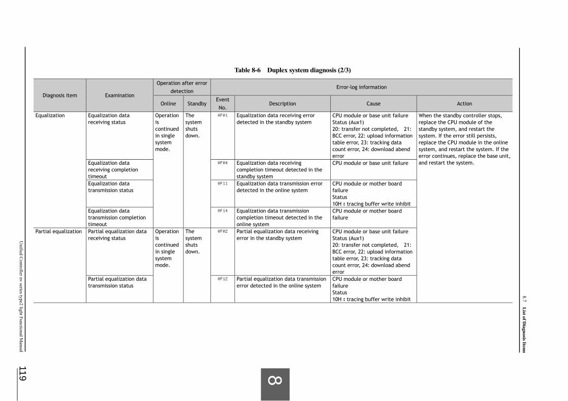
8.7 List of D
iagnosis Items
119
U
nified Controller nv series type2 light Functional M
anual
Table 8-6 Duplex system diagnosis (2/3)
Diagnosis item Examination
Operation after error detection
Error-log information
Online Standby Event No.
Description Cause Action
Equalization Equalization data receiving status
Operation is continued in single system mode.
The system shuts down.
0F01 Equalization data receiving error detected in the standby system
CPU module or base unit failure Status (Aux1) 20: transfer not completed, 21: BCC error, 22: upload information table error, 23: tracking data count error, 24: download abend error
When the standby controller stops, replace the CPU module of the standby system, and restart the system. If the error still persists, replace the CPU module in the online system, and restart the system. If the error continues, replace the base unit, and restart the system. Equalization data
receiving completion timeout
0F04 Equalization data receiving completion timeout detected in the standby system
CPU module or base unit failure
Equalization data transmission status
0F11 Equalization data transmission error detected in the online system
CPU module or mother board failure Status 10H: tracing buffer write inhibit
Equalization data transmission completion timeout
0F14 Equalization data transmission completion timeout detected in the online system
CPU module or mother board failure
Partial equalization Partial equalization data receiving status
Operation is continued in single system mode.
The system shuts down.
0F02 Partial equalization data receiving error in the standby system
CPU module or base unit failure Status (Aux1) 20: transfer not completed, 21: BCC error, 22: upload information table error, 23: tracking data count error, 24: download abend error
Partial equalization data transmission status
0F12 Partial equalization data transmission error detected in the online system
CPU module or mother board failure Status 10H: tracing buffer write inhibit

Chapter 8 R
AS Function
120
6F8C1576
Table 8-6 Duplex system diagnosis (3/3)
Diagnosis item Examination
Operation after error detection
Diagnosis item
Online Standby Event No.
Description Cause Action
Duplex status CPU module status of other system (NX_STS_OTH_DOWN)
Operation is continued in single system mode.
Transition to single system operation mode to continue operation.
0F06 System shutdown caused by CPU module error detected in the other system
CPU module error in the other system
Replace the CPU module in the other system, and restart the system. If the error still persists, replace the CPU module and base unit of own system, and restart the system.
Shutdown of the other system in single system mode
The system shuts down.
0F29 Single operation of the CPU module detected in the other system
Error in the other system Check the error in the other system, and take appropriate actions.
Duplex tracking bus Power off or tracking bus status of the other system (NX_STS_OTH_POFF)
Operation is continued in single system mode.
The system shuts down.
0F07 Tracking bus diagnosis signal error Power off, base unit failure, or cable disconnection in the other system
Turn on power of the other system, and restart the system. If the error still persists, replace the CPU module and base unit of own system, and restart the system.
Confirmation signal status of the other system (NX_STS_CABLE_CUT)
0F08 Confirmation signal error detected in the other system
The other system not installed, base unit failure or cable disconnection in the other system
Check that both primary and secondary CPU modules are installed, and restart the system. If the error continues, replace the tracking cable or base unit, and restart the system.
Control authority signal status
0F09 Control authority signal error The other system in operation, base unit failure or cable disconnection in the other system
Check the other system status, and restart the system. If the error still persists, replace the CPU module and base unit of own system, and restart the system.
Duplex software status (NX_STS_CABLE_CUT)
0F0B Duplex software status error CPU module or mother board failure
When the standby controller stops, replace the CPU module of the standby system, and restart the system. If the error still persists, replace the CPU module in the online system, and restart the system. If the error continues, replace the base unit, and restart the system.
Duplex hardware status (NX_STS_CABLE_CUT)
0F0C Duplex hardware status error CPU module or mother board failure
Remark
(Note) For replacing the base unit and modules described in the above tables, see Unified Controller nv Series type2 light Controller Unit Instruction Manual (6F8C1575).

121
Appendix A Function Specification and System Variable (ZW)
A.1 Function Specifications ····················································· 122
A.2 List of System Variables (ZW)············································· 125
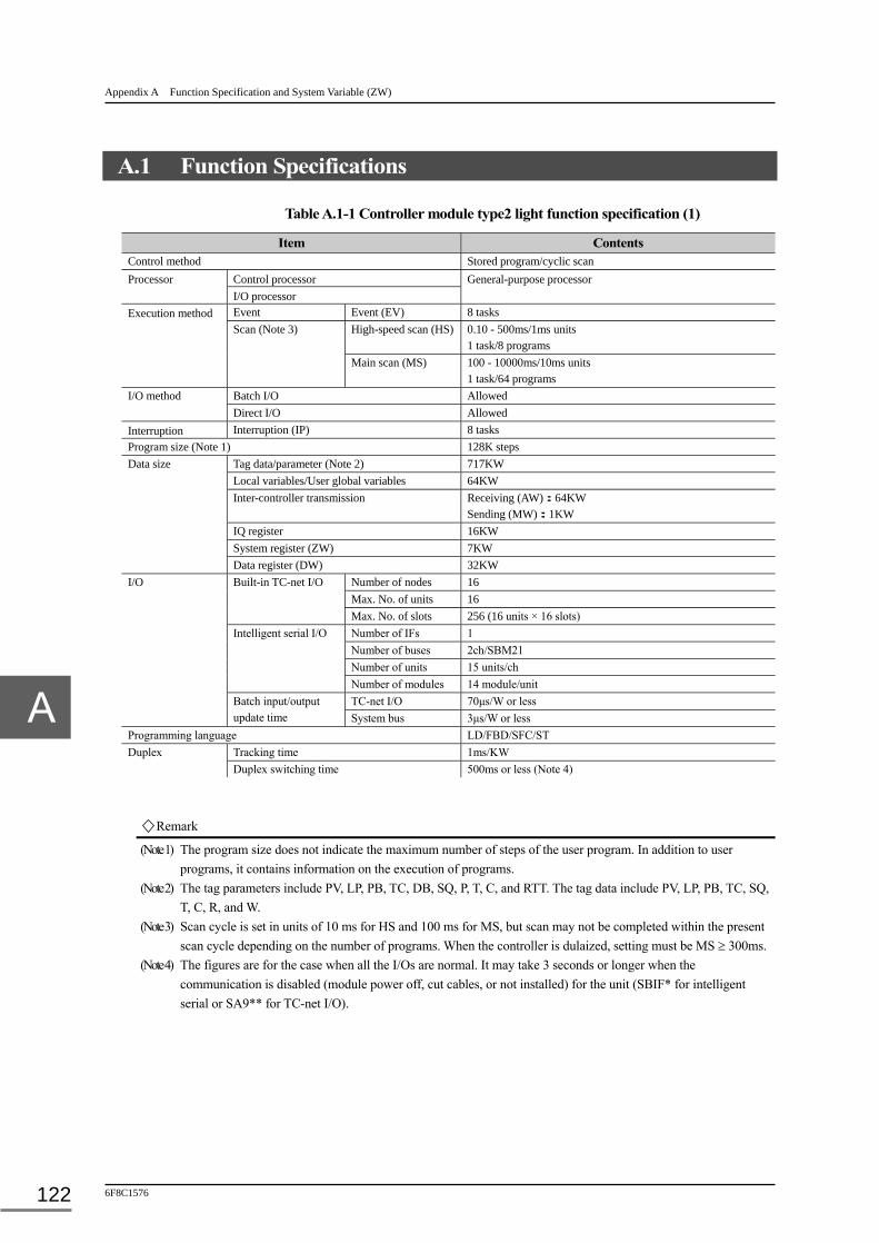
Appendix A Function Specification and System Variable (ZW)
6F8C1576 122
A.1 Function Specifications
Table A.1-1 Controller module type2 light function specification (1)
Item Contents Control method Stored program/cyclic scan
Processor Control processor General-purpose processor I/O processor
Execution method Event Event (EV) 8 tasks Scan (Note 3) High-speed scan (HS) 0.10 - 500ms/1ms units
1 task/8 programs Main scan (MS) 100 - 10000ms/10ms units
1 task/64 programs I/O method Batch I/O Allowed
Direct I/O Allowed Interruption Interruption (IP) 8 tasks Program size (Note 1) 128K steps Data size Tag data/parameter (Note 2) 717KW
Local variables/User global variables 64KW Inter-controller transmission Receiving (AW): 64KW
Sending (MW): 1KW IQ register 16KW System register (ZW) 7KW Data register (DW) 32KW
I/O Built-in TC-net I/O Number of nodes 16 Max. No. of units 16
Max. No. of slots 256 (16 units × 16 slots) Intelligent serial I/O Number of IFs 1
Number of buses 2ch/SBM21 Number of units 15 units/ch Number of modules 14 module/unit
Batch input/output update time
TC-net I/O 70μs/W or less System bus 3μs/W or less
Programming language LD/FBD/SFC/ST Duplex Tracking time 1ms/KW
Duplex switching time 500ms or less (Note 4)
Remark
(Note 1) The program size does not indicate the maximum number of steps of the user program. In addition to user programs, it contains information on the execution of programs.
(Note 2) The tag parameters include PV, LP, PB, TC, DB, SQ, P, T, C, and RTT. The tag data include PV, LP, PB, TC, SQ, T, C, R, and W.
(Note 3) Scan cycle is set in units of 10 ms for HS and 100 ms for MS, but scan may not be completed within the present scan cycle depending on the number of programs. When the controller is dulaized, setting must be MS 300ms.
(Note 4) The figures are for the case when all the I/Os are normal. It may take 3 seconds or longer when the communication is disabled (module power off, cut cables, or not installed) for the unit (SBIF* for intelligent serial or SA9** for TC-net I/O).
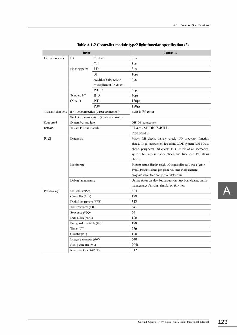
A.1 Function Specifications
Unified Controller nv series type2 light Functional Manual 123
Table A.1-2 Controller module type2 light function specification (2)
Item Contents Execution speed Bit Contact 2μs
Coil 3μs Floating point LD 3μs
ST 10μs Addition/Subtraction/
Multiplication/Division 6μs
PID_P 36μs Standard I/O
(Note 1) IND 50μs PID 130μs PB8 180μs
Transmission port nV-Tool connection (direct connection) Built-in Ethernet Socket communication (instruction word)
Supported
network
System bus module OIS-DS connection TC-net I/O bus module FL-net、MODBUS-RTU、
Profibus-DP RAS Diagnosis Power fail check, battery check, I/O processer function
check, illegal instruction detection, WDT, system ROM BCC
check, peripheral LSI check, ECC check of all memories,
system bus access parity check and time out, I/O status
check. Monitoring System status display (incl. I/O status display), trace (error,
event, transmission), program run time measurement,
program execution congestion detection
Debug/maintenance Online status display, backup/restore function, defrag, online
maintenance function, simulation function
Process tag Indicator (#PV) 384 Controller (#LP) 128 Digital instrument (#PB) 512 Timer/counter (#TC) 64 Sequence (#SQ) 64 Data block (#DB) 128 Polygonal line table (#P) 128 Timer (#T) 256 Counter (#C) 128 Integer parameter (#W) 640 Real parameter (#R) 2048 Real time trend (#RTT) 512

Appendix A Function Specification and System Variable (ZW)
6F8C1576 124
Remark
(Note 1) The performance of the standard I/O depends on the following condition: IND: Real I/O (device in normal status), PV normal (no alarm), no temperature/pressure
correction PID: Real I/O (device in normal status), MOD = C, analog output, no alarm PB8: Real I/O (device in normal status), button operation, no alarm, MOD = A

A.2 List of System Variables (ZW)
Unified Controller nv series type2 light Functional Manual 125
A.2 List of System Variables (ZW)
■ General information (read only)
zw Usage
F E D C B A 9 8 7 6 5 4 3 2 1 0
0000 Calendar date (local time)
Year ×10 ×1 0001 Month ×10 ×1 0002 Day ×10 ×1 0003 Hour ×10 ×1 0004 Minute ×10 ×1 0005 Second ×10 ×1 0008 Ethernet IP address setting switch
for nV-Tool 7 6 5 4 3 2 1 0
<7 to 4> Upper setting value: 0 to F <3 to 0> Lower setting value: 0 to F
0009 Operation mode key switch 2 1 0 <0> HALT
<1> RUN <2> P-RUN
0010 Front panel dip switch 7 6 5 4 3 2 1 0 <0> SW-1 <1> SW-2 <2> SW-3 <3> SW-4 <4> SW-5 (fixed to 0) <5> SW-6 (fixed to 0) <6> SW-7 <7> SW-8
0011 Duplex primary/secondary specification
0 0: Primary 1: Secondary

Appendix A Function Specification and System Variable (ZW)
6F8C1576 126
■ Operation information (read only)
zw Usage
F E D C B A 9 8 7 6 5 4 3 2 1 0 0020 Operation mode Own phase 0021 (Remark) Target phase 0022 0023 Error information 15 14 3 2 0 <0> Battery error
<2> Temperature error <3> Calendar error (Note) F/E is fixed for contact force. <14> fixed to 1 <15> fixed to 0
0024 Partial equalization information Number of times of partial equalization (maximum value) 0025 Number of times of partial equalization (current value) 0026 Timing relay 7 6 5 4 3 2 1 0
<0> 0.1sec <1> 0.2sec <2> 0.4sec <3> 0.8sec <4> 1sec <5> 2sec <6> 4sec <7> 8sec (Note) The time set on each bit indicates the interval (sec) of setting the to ON and OFF.
Remark
• The table below shows the association of code numbers (hex) and operation modes. Code No. Operation mode Remark 0x0000 INZ For details of the operation modes, see
Chapter 2, 2.3.2 Types and function of operation mode in single operation and 2.3.3 Operation mode and function in duplex operation.
0x0003 DL-WAIT 0x000E HALT 0x000F ERROR 0x0010 PHASE-2 0x0012 S-HOLD 0x0013 0x0014 0x0015 0x0016 0x002A RCV-H 0x0018 O-HOLD 0x0019 0x001B 0x001C 0x0020 EQL-RUN 0x003A ODD-RUN 0x0038 MASTER-RUN 0x0039 SLAVE-RUN 0x003D RUN 0x00FC The other system not mounted, or tracking cable is
not connected.
0x00FD The power supply of the other system is turned off. 0x00FE The other system’s CPU shut down.

A.2 List of System Variables (ZW)
Unified Controller nv series type2 light Functional Manual 127
zw Usage
F E D C B A 9 8 7 6 5 4 3 2 1 0 0045 Execution cycle High-speed scan cycle/setting value (ms) 0046 Execution cycle of the task of the high-speed or main scan under execution
(floating point value) Scan cycle × Sub schedule value (ms)
0047
0048 Congestion information High-speed scan congestion information (0:Normal 1:In congestion 2:Recovery)
0049 Congestion count 0050 Main scan congestion information
(0:Normal 1:In congestion 2:Recovery) 0051 Congestion count 0052 Task initialization information 15 14 13 <15> Initialization sign(with long interruption startup or DL)
<14> Duplex switching sign <13> RUN startup sign
0053 Program errors representative information
0 <0> 1 if an error occurs 0054 Program errors detailed information 15 14 13 12 11 10 9 8 7 6 5 4 3 2 1 0 <0> Illegal instruction
<1> POU undefined <2> Stack error <3> Real number operation error <4> Memory reference boundary error <5> Execution boundary over error <6> <7> <8> Division error <9> BCD data error <10> Table operation error <11> Encode error <12> <13> <14> Non-numerical input <15> Operation result overflow
0055 0056 Tracking amount display High-speed scan tracking amount(W) 0057 0058 Main scan tracking amount(W) 0059
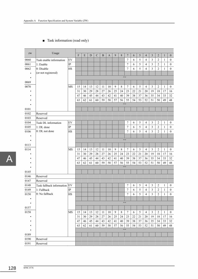
Appendix A Function Specification and System Variable (ZW)
6F8C1576 128
■ Task information (read only)
zw Usage
F E D C B A 9 8 7 6 5 4 3 2 1 0 0060 Task enable information
1: Enable 0: Disable (or not registered)
EV 7 6 5 4 3 2 1 0 0061 IP 7 6 5 4 3 2 1 0 0062 HS 7 6 5 4 3 2 1 0
・
・ ~ 0069 0070 MS 15 14 13 12 11 10 9 8 7 6 5 4 3 2 1 0
・ 31 30 29 28 27 26 25 24 23 22 21 20 19 18 17 16
・ 47 46 45 44 43 42 41 40 39 38 37 36 35 34 33 32
・ 63 62 61 60 59 58 57 56 55 54 53 52 51 50 49 48
・ ~ 0101 0102 Reserved 0103 Reserved 0104 Task DL information
1: DL done 0: DL not done
EV 7 6 5 4 3 2 1 0 0105 IP 7 6 5 4 3 2 1 0 0106 HS 7 6 5 4 3 2 1 0
・
・ ~ 0113 0114 MS 15 14 13 12 11 10 9 8 7 6 5 4 3 2 1 0
・ 31 30 29 28 27 26 25 24 23 22 21 20 19 18 17 16
・ 47 46 45 44 43 42 41 40 39 38 37 36 35 34 33 32
・ 63 62 61 60 59 58 57 56 55 54 53 52 51 50 49 48
・ ~ 0145 0146 Reserved 0147 Reserved 0148 Task fallback information
1: Fallback 0: No fallback
EV 7 6 5 4 3 2 1 0 0149 IP 7 6 5 4 3 2 1 0 0150 HS 7 6 5 4 3 2 1 0
・
・ ~ 0157 0158 MS 15 14 13 12 11 10 9 8 7 6 5 4 3 2 1 0
・ 31 30 29 28 27 26 25 24 23 22 21 20 19 18 17 16
・ 47 46 45 44 43 42 41 40 39 38 37 36 35 34 33 32
・ 63 62 61 60 59 58 57 56 55 54 53 52 51 50 49 48
・ ~ 0189 0190 Reserved 0191 Reserved

A.2 List of System Variables (ZW)
Unified Controller nv series type2 light Functional Manual 129
■ Task fallback information
zw Usage
F E D C B A 9 8 7 6 5 4 3 2 1 0 0200 Task fallback error cord Large classification 0201 Middle classification 0202 Small classification 0203 Task fallback error information Task type number (0:EV, 2:IP, 3:HS, 4:MS) 0204 Task entry number (0 to 63) 0208 Fallback/shutdown
specification 0
<0> 0:Task fallback 1:Shutdown
Remark
• The task fallback/shutdown specification (ZW208) can be set from the EV5 task program. System shutdown is effective for the single system operation or independent operation in the duplex system. An error causing the task fallback in the duplex system makes the online system to be switched.

Appendix A Function Specification and System Variable (ZW)
6F8C1576 130
■ I/O interrupt task (IP) information
zw Usage
F E D C B A 9 8 7 6 5 4 3 2 1 0 0236 I/O interrupt task
IP0 ON status 15 14 13 12 11 10 9 8 7 6 5 4 3 2 1 0
0237 OFF status 15 14 13 12 11 10 9 8 7 6 5 4 3 2 1 0 0238 Factor 1:TC-netI/O status change 4:Event program startup(START_P) 0239 I/O interrupt task
IP1 ON status 15 14 13 12 11 10 9 8 7 6 5 4 3 2 1 0
0240 OFF status 15 14 13 12 11 10 9 8 7 6 5 4 3 2 1 0 0241 Factor 1:TC-netI/O status change 4:Event program startup(START_P) 0242 I/O interrupt task
IP2 ON status 15 14 13 12 11 10 9 8 7 6 5 4 3 2 1 0
0243 OFF status 15 14 13 12 11 10 9 8 7 6 5 4 3 2 1 0 0244 Factor 1:TC-netI/O status change 4:Event program startup(START_P) 0245 I/O interrupt task
IP3 ON status 15 14 13 12 11 10 9 8 7 6 5 4 3 2 1 0
0246 OFF status 15 14 13 12 11 10 9 8 7 6 5 4 3 2 1 0 0247 Factor 1:TC-netI/O status change 4:Event program startup(START_P) 0248 I/O interrupt task
IP4 ON status 15 14 13 12 11 10 9 8 7 6 5 4 3 2 1 0
0249 OFF status 15 14 13 12 11 10 9 8 7 6 5 4 3 2 1 0 0250 Factor 1:TC-netI/O status change 4:Event program startup(START_P) 0251 I/O interrupt task
IP5 ON status 15 14 13 12 11 10 9 8 7 6 5 4 3 2 1 0
0252 OFF status 15 14 13 12 11 10 9 8 7 6 5 4 3 2 1 0 0253 Factor 1:TC-netI/O status change 4:Event program startup(START_P) 0254 I/O interrupt task
IP6 ON status 15 14 13 12 11 10 9 8 7 6 5 4 3 2 1 0
0255 OFF status 15 14 13 12 11 10 9 8 7 6 5 4 3 2 1 0 0256 Factor 1:TC-netI/O status change 4:Event program startup(START_P) 0257 I/O interrupt task
IP7 ON status 15 14 13 12 11 10 9 8 7 6 5 4 3 2 1 0
0258 OFF status 15 14 13 12 11 10 9 8 7 6 5 4 3 2 1 0 0259 Factor 1:TC-netI/O status change 4:Event program startup(START_P)
Remark
• TC-netI/O change of state when an I/O interrupt task started by the setting of status change indication is shown in the ON/OFF status. As for the ON status, 1 is set at the time of OFF → ON change. As for the OFF status, 1 is set at the time of ON → OFF change. For the setting of status change indication, see 7.1.4 Status change indication in Chapter 7.
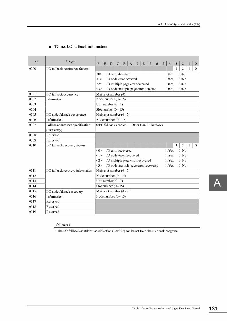
A.2 List of System Variables (ZW)
Unified Controller nv series type2 light Functional Manual 131
■ TC-net I/O fallback information
zw Usage
F E D C B A 9 8 7 6 5 4 3 2 1 0 0300 I/O fallback occurrence factors 3 2 1 0
<0> I/O error detected 1:Yes, 0:No <1> I/O node error detected 1:Yes, 0:No <2> I/O multiple page error detected 1:Yes, 0:No <3> I/O node multiple page error detected 1:Yes, 0:No
0301 I/O fallback occurrence information
Main slot number (0) 0302 Node number (0 - 15) 0303 Unit number (0 - 7) 0304 Slot number (0 - 15) 0305 I/O node fallback occurrence
information Main slot number (0 - 7)
0306 Node number (0~15) 0307 Fallback/shutdown specification
(user entry) 0:I/O fallback enabled Other than 0:Shutdown
0308 Reserved 0309 Reserved 0310 I/O fallback recovery factors 3 2 1 0
<0> I/O error recovered 1: Yes, 0: No <1> I/O node error recovered 1: Yes, 0: No <2> I/O multiple page error recovered 1: Yes, 0: No <3> I/O node multiple page error recovered 1: Yes, 0: No
0311 I/O fallback recovery information Main slot number (0 - 7) 0312 Node number (0 - 15) 0313 Unit number (0 - 7) 0314 Slot number (0 - 15) 0315 I/O node fallback recovery
information Main slot number (0 - 7)
0316 Node number (0 - 15) 0317 Reserved 0318 Reserved 0319 Reserved
Remark
• The I/O fallback/shutdown specification (ZW307) can be set from the EV4 task program.

Appendix A Function Specification and System Variable (ZW)
6F8C1576 132
■ User system alarm failure bit area (user entry)
zw Usage
F E D C B A 9 8 7 6 5 4 3 2 1 0 Alarm A1 1300 Group G1 Major failure bit 7 6 5 4 3 2 1 0 1301 Minor failure bit 7 6 5 4 3 2 1 0 1302 Group G2 Major failure bit 7 6 5 4 3 2 1 0 1303 Minor failure bit 7 6 5 4 3 2 1 0
・ ~ 1362 Group G32 Major failure bit 7 6 5 4 3 2 1 0 1363 Minor failure bit 7 6 5 4 3 2 1 0 Alarm A2 1364 Group G1 Major failure bit 7 6 5 4 3 2 1 0 1365 Minor failure bit 7 6 5 4 3 2 1 0 1366 Group G2 Major failure bit 7 6 5 4 3 2 1 0 1367 Minor failure bit 7 6 5 4 3 2 1 0
・ ~ 1426 Group G32 Major failure bit 7 6 5 4 3 2 1 0 1427 Minor failure bit 7 6 5 4 3 2 1 0
Remark
• Alarms are transferred to the OIS by setting the relevant alarm bit from the user program. • Alarms are roughly divided into two (A1 and A2). Every alarm is classified as A1 or A2 in the OIS alarm
screen. • There are 32 alarm groups in which major failure bits (0 to 7) and minor failure bits (0 to 7) are included. • Before using alarms, entry of use permit is required for in units of alarms, groups and failure bits. The user system alarm mask bit table in the next page shows the settings.

A.2 List of System Variables (ZW)
Unified Controller nv series type2 light Functional Manual 133
■ User system alarm mask bit area (user entry)
zw Usage
F E D C B A 9 8 7 6 5 4 3 2 1 0 1500 Reserved 1501 Alarm entry A2 A1
A1:Alarm 1 A2:Alarm 2 A1 1502 1503
Group entry G16 G15 G14 G13 G12 G11 G10 G9 G8 G7 G6 G5 G4 G3 G2 G1 G32 G31 G30 G29 G28 G27 G26 G25 G24 G23 G22 G21 G20 G19 G18 G17
1504 1505
A1.G1 Major failure bit entry 7 6 5 4 3 2 1 0 Minor failure bit entry 7 6 5 4 3 2 1 0
1506 1507
A1.G2 Major failure bit entry 7 6 5 4 3 2 1 0 Minor failure bit entry 7 6 5 4 3 2 1 0
・ ~ ~ 1566 1567
A1.G32 Major failure bit entry 7 6 5 4 3 2 1 0 Minor failure bit entry 7 6 5 4 3 2 1 0
A2 1568 1569
Group entry G16 G15 G14 G13 G12 G11 G10 G9 G8 G7 G6 G5 G4 G3 G2 G1 G32 G31 G30 G29 G28 G27 G26 G25 G24 G23 G22 G21 G20 G19 G18 G17
1570 1571
A2.G1 Minor failure bit entry 7 6 5 4 3 2 1 0 Minor failure bit entry 7 6 5 4 3 2 1 0
1572 1573
A2.G2 Minor failure bit entry 7 6 5 4 3 2 1 0 Minor failure bit entry 7 6 5 4 3 2 1 0
・ ~ ~ 1632 1633
A2.G32 Major failure bit entry 7 6 5 4 3 2 1 0 Minor failure bit entry 7 6 5 4 3 2 1 0
Remark
• Alarms inhibit/permit can be entered in units of alarms, groups and failure bits (0: inhibit, 1: permit).

Appendix A Function Specification and System Variable (ZW)
6F8C1576 134
■ Inter-controller transmission bit map area
zw Usage Controller number (1 - 64)
F E D C B A 9 8 7 6 5 4 3 2 1 0 1700
Inter-controller transmission diagnosis registration map
16 15 14 13 12 11 10 9 8 7 6 5 4 3 2 1
1701 32 31 30 29 28 27 26 25 24 23 22 21 20 19 18 17
1702 48 47 46 45 44 43 42 41 40 39 38 37 36 35 34 33
1703 64 63 62 61 60 59 58 57 56 55 54 53 52 51 50 49
1704
Inter-controller transmission diagnosis health map
16 15 14 13 12 11 10 9 8 7 6 5 4 3 2 1
1705 32 31 30 29 28 27 26 25 24 23 22 21 20 19 18 17
1706 48 47 46 45 44 43 42 41 40 39 38 37 36 35 34 33
1707 64 63 62 61 60 59 58 57 56 55 54 53 52 51 50 49
Remark
• For the controllers entered in the inter-controller transmission diagnosis registration map, an alarm (minor failure) is sent to the OIS for the unsatisfactory result of diagnosis.(0: Not diagnosed, 1: Diagnosed)
• The inter-controller transmission diagnosis heath map explicitly indicates the inter-controller transmission status, and diagnostic result of all controllers connected to the network regardless of the entry in the map. (o: Error, 1: Normal)
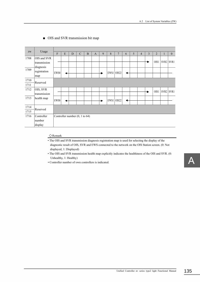
A.2 List of System Variables (ZW)
Unified Controller nv series type2 light Functional Manual 135
■ OIS and SVR transmission bit map
zw Usage
F E D C B A 9 8 7 6 5 4 3 2 1 0 1708 OIS and SVR
transmission diagnosis registration map
OIS1 SVR2 SVR1
1709 EWS8 EWS1 OIS22
1710 Reserved
1711 1712 OIS, SVR
transmission health map
OIS1 SVR2 SVR1
1713 EWS8 EWS1 OIS22
1714 Reserved
1715 1716 Controller
number display
Controller number (0, 1 to 64)
Remark
• The OIS and SVR transmission diagnosis registration map is used for selecting the display of the diagnostic result of OIS, SVR and EWS connected to the network on the OIS Station screen. (0: Not displayed, 1: Displayed)
• The OIS and SVR transmission health map explicitly indicates the healthiness of the OIS and SVR. (0: Unhealthy, 1: Healthy)
• Controller number of own controllers is indicated.

136
Appendix B Precautions on Use and Restrictions This chapter describes the precautions on use, changes, and restrictions for the Unified Controller nv
series type2 light.
B.1 Notes on Use and Modifications ··········································· 137
B.2 Application Registration in Duplexing ·································· 139
B.2.1 Identification of duplexing ········································ 139
B.2.2 Parameter changes (for future use) ······························· 139
B.2.3 Event tasks in switching ··········································· 139
B.2.4 Identification of switching ········································ 140
B.3 Restrictions on Process Tag Output ······································ 141

B.1 Notes on Use and Modifications
Unified Controller nv series type2 light Functional Manual 137
B.1 Notes on Use and Modifications
■ General
Unified controller type2 light is designed to operate by connecting to the CIMAC-DS system via
a network.
■ Memory retention
Unified controller type2 light saves data in the battery backed memory for retaining memory in
the event of shutdown. If this shutdown power supply is not fully charged, memory will be lost
when power is down, and control cannot be continued when power is recovered.
The memory is retained for 90 days without power supply. The charge level of the backup
battery is indicated on the battery LED.
■ I/O
Unified controller type2 light is designed assuming the TC-net I/O module is used. The TC-net
I/O module realizes online maintenance functions such as installation/removal online as in the
conventional serial I/O (such as intelligent I/O modules). However, maintenance and diagnosis
functions equivalent to the conventional I/O may not be present, such that many I/O modules do
not have any CPU.
Intelligent serial I/O is supported to respond to future update. SBIF interface module (SBM21) is
required to connection.
■ Process tag
The supported process tags are equivalent to other controllers in CIEMAC-DS series. However,
the total number of indicator tags (#PV) is decreased to 384, controller tags (#LP) to 128, and
#PB to 512.
For details, see 6.4 Details of Standard I/O Processing in Chapter 6.
Appendix B Precautions on Use and Restrictions
6F8C1576 138
■ System variable (ZW)
The configuration of the system variable (ZW) is equivalent to the other controllers in
CIEMAC-DS series. However, the register numbers may be increased/decreased according to
the type of supported I/O. When using conventional applications, check with the register number
table.
For details of the system variable (ZW), see Appendix A, A.2 List of System Variables (ZW).
■ Instruction word
The instruction word system is compatible with Integrated Controller L series,in the unified
controller type2 light. However, the instruction names of part of I/O, communication and time
related instructions were changed.
■ Engineering
The engineering environment of unified controller nv series is nV/V series engineering tool 4
which is compatible with integrated controller V series.
The types of user programs are according to the Integrated Controller V series. However, SS
(super high-speed scan) tasks and BG (background) tasks are not implemented.
■ Self diagnosis
Unified controller type2 light conducts self-diagnoses including the power-on diagnosis, runtime
(RUN) diagnosis, diagnoses during operation and regular diagnoses. The result of self-diagnosis
is recorded in the system log, which is viewed on the nV-Tool screen.
For memory diagnosis of unified controller type2 light, ECC is adopted.
■ Network
Unified controller type2 light provides the USEND_N/URCV_N instruction for Ethernet
communication (TCP/IP or UDP/IP). Since these communication instructions use control LAN
to connect to OIS, pay attention to the amount of communication (the number of packets per
second). The network should be designed so that the received amount of communication on
Ethernet connected to DS on the type2 light controller is 100 packets or less per second at
normal condition.

B.2 Application Registration in Duplexing
Unified Controller nv series type2 light Functional Manual 139
B.2 Application Registration in Duplexing
B.2.1 Identification of duplexing
Normally, the control program does not have to be aware that the controller is duplexed.
The result of the user program in the online system is automatically transferred to the standby
system for equalization (this is called the duplex tracking).
The results of operations or changes from the outside such as OIS-DS are automatically reported
to the standby side and equalized, so the operation can be inherited (this is called the partial
equalization).
These functions allow the continuation of control when the online system is switched.
B.2.2 Parameter changes (for future use)
The instruction words for equalizing the standby system when parameters are changed in the
user program are provided (these instruction words are called the duplex instruction words).
These instruction words are listed below Instruction Instruction type Store ST (INT, UINT, W, DINT, DW, REAL) Set and store SET (INT, UINT, W, DINT, DW, REAL) Store bit STB Set and store bit SETB Interrupt tag SSV_P, SMV_P, SCV_P
Note
• If the process tag parameters are frequently changed in the user program, the load of the equalizing function is increased, and the run-time of the user program is prolonged. Avoid a program requiring frequent changes of process tag parameters as much as possible.
B.2.3 Event tasks in switching
When duplex switching occurs, the event task (EV3) starts up.
The event task (EV3) is activated only once when the online system is switched. Use this task
when common processing is required during switching.

Appendix B Precautions on Use and Restrictions
6F8C1576 140
B.2.4 Identification of switching
When duplex switching occurs in the controller, the flag (ZW52 <E>) indicating switching is set
for the first one scan after the switching. The control program can monitor this flag to identify
the presence of switching occurred.
The controller is designed to shorten the time required for duplex switching as much as possible
for seamless switching operation. However, it may be impossible to determine if the controller
state is completely normal immediately before switching depending on the effect of failure
causing the switching. Monitor the switching flag with the control program, and take appropriate
measures when switching is identified for important control targets.

B.3 Restrictions on Process Tag Output
Unified Controller nv series type2 light Functional Manual 141
B.3 Restrictions on Process Tag Output
The output point variable (OA) of the process tag can be registered either by directly registering
the I/O module, or registering the batch I/O register. An error may be caused depending on the
specification. Restrictions on handling the process tag output are described below.
■Restrictions on registration of the I/O module in the process tag
When an I/O module is registered in the output point variable (OA) of the process tag, and an
I/O variable is allocated to the same I/O module, the data output from the process tag to the I/O
module may be cleared to zero.
When an I/O variable is given to the I/O module, the batch I/O register is automatically
allocated, and data is transferred between the batch I/O register and the I/O module. This
causes the data on the I/O module to be cleared for the following reason:
Data is directly output to the I/O module (output) from the process tag.
The batch I/O register is overwritten during batch I/O (zero data).
To prevent this, do not set an I/O variable on he I/O module directly registered to the output
point variable (OA).
Note
Take the following into consideration when using the I/O module: • Direct output and output using an I/O variable (batch I/O) should not be used
concurrently in the same I/O module. • Divide I/O modules to those used with an I/O variable and those for direct output
without an I/O variable from the beginning.
0
Direct output from the process tag
②
I/O module (output)
Batch I/O register

Appendix B Precautions on Use and Restrictions
6F8C1576 142
■ Coexistence of program output and PB (pushbutton) tag output in one word
As described above, output from the program (with an I/O variable) and output from the PB
(pushbutton) tag should not be present in one work (16 bits) in principle. If, however,
coexistence is required, for example, to substitute output from the integrated controller, set
the address of I/O with a variable on the PB (pushbutton) tag output address (OA1 to OA8).
Set the address as follows:
Verify the logical address of the output address (OA1 to OA8) using the new
instrument tag editor:
Logical address
00-NN-UU-MM-PP: NN = Node No. (03 - 34), UU = Unit No. (01),
MM = Module No. (00 - 15), PP = Point No. (01 - 64)
Find the work number and bit number from the point number:
word number = (PP-1) / 16
bit number = (PP-1) mod 16
(Example) If PP = 01, word = 0 and bit = 0
If PP = 64, word = 3 and bit = 15
Open the I/O variable screen of the module (NN/UU/MM) and find the IQ No. for the
word number obtained in the previous step ().
Rewrite the logical address of the output address (OA1 to OA8) to the physical
address using the new tag editor.
%MX5.QQQQ.bit => 00-NN-UU-MM-PP
QQQQ: IQ No. found in step
Bit: bit No. found in step
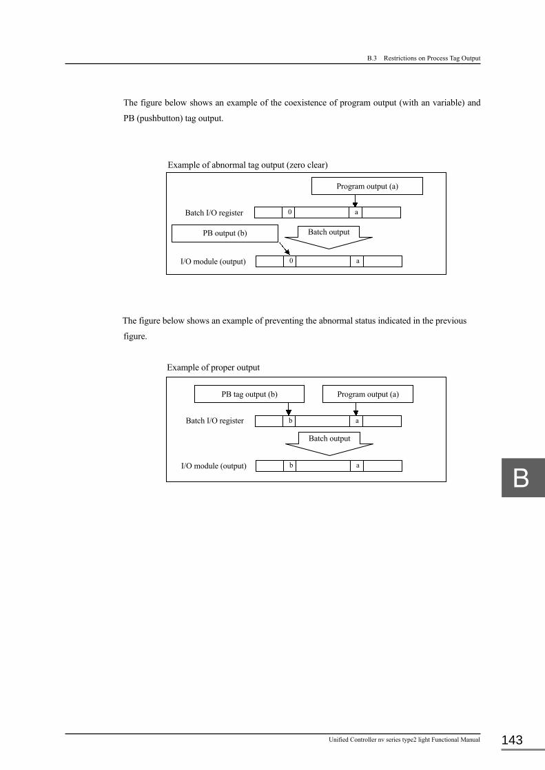
B.3 Restrictions on Process Tag Output
Unified Controller nv series type2 light Functional Manual 143
The figure below shows an example of the coexistence of program output (with an variable) and
PB (pushbutton) tag output.
Example of abnormal tag output (zero clear)
The figure below shows an example of preventing the abnormal status indicated in the previous
figure.
Example of proper output
PB output (b) Batch output
I/O module (output)
Batch I/O register 0 a
Program output (a)
0 a
I/O module (output)
Batch I/O register
Program output (a) PB tag output (b)
Batch output
b a
b a

144
Appendix C List of Process Tags The tag parameters and data of process tags are explained in the order of display by the tag editor of
the nV-Tool in this section.
C.1 PV (Indicator) ································································ 145
C.1.1 Parameters··························································· 145
C.1.2 Data ·································································· 153
C.2 LP (Controller) ······························································· 157
C.2.1 Parameters··························································· 157
C.2.2 Data ·································································· 162
C.3 PB (Pushbutton) ······························································ 166
C.3.1 Parameters··························································· 166
C.3.2 Data ·································································· 170
C.4 TC (Timer/Counter) ························································· 173
C.4.1 Parameters··························································· 173
C.4.2 Data ·································································· 175
C.5 DB (Data Block) ······························································ 177
C.5.1 Parameters··························································· 177
C.6 SQ (Sequence Operation Equipment) ··································· 178
C.6.1 Parameters··························································· 178
C.6.2 Data ·································································· 179

C.1 PV (Indicator)
Unified Controller nv series type2 light Functional Manual 145
C.1 PV (Indicator)
The PV (indicator) tag registers general data on interface signals for the input sensor, standard input processing and indication type of instrument.
C.1.1 Parameters
The input conditions are itemized and each condition begins with ●. Input is allowed only when all conditions are met. The parameter marked with ■ in the description column is indicated in bit array. The parameter marked with ○ in the tag type (TYPE) column is related to that tag type. The parameter marked with ○ in its compound tag column is given priority when it is registered in #LP or #PB.
Item name Abbr. Description Tag type (TYPE) Compound
tag IND (AI)
IND (PI) AMM PFI TTL
(AI) TTL (PI) WND #LP #PB
Tag number TAG Specifies the identification number given to the instrument. ●Set a number in up to 16 characters including numbers, letters and underbars. Begin the character-string with a letter. ●Use a unique number in the system. ●Do not use the reserved word in the system. ・Lower and upper case letters are not discriminated. All are converted to upper case letters.
・Note the following when combining TAG with the LP or PB tag as the compound tag: (1) Do not use the same tag number as the LP or PB
tag. Do not leave the PV tag number blank. (2) When the tag is searched on OIS, only the LP or
PB tag number is indicated. < Example > Search on OIS results in the output of LP tag number “PID01” when the PID consists of the PV and LP tags, and “PID01” is set on the LP tag number and “PID01PV” on the PV1 tag number.
○ ○ ○ ○ ○ ○ ○ ○ ○
Tag name NAME Specifies the name of this instrument. ●Up to 32 characters. ○ ○ ○ ○ ○ ○ ○ ○ ○
Tag type TYPE ●Select the instrument function type from those listed below. ・Not used ・IND (Indicator) ・AMM (Ammeter) ・PFI (Power-factor meter) ・TTL (Integrating meter) ・WND (Wind meter)
○ ○ ○ ○ ○ ○ ○ × ×
Display pattern model number
MDL Specifies the instrument display pattern on OIS. ●0 - 9. ・Enter 0 for the standard pattern. ・Enter 1 to 9 for the indication pattern created by the user.
○ ○ ○ ○ ○ ○ ○ ○ ○
Signal type number AREA Specifies the instrument signals for grouping in the whole system. ●0 - 63.
○ ○ ○ ○ ○ ○ ○ ○ ○
Automatic screen display number
SCNO Sets the OIS screen automatically selected when an alarm is generated. ●0 - 1024. ・Enter 0 for disabling the automatic selection.
○ ○ ○ ○ ○ ○ ○ ○ ○
Operation inhibition LOCK Specifies whether to permit or inhibit operator action when an instrument tag is set on the OIS. ●Permit, Inhibit.
○ ○ ○ ○ ○ ○ ○ ○ ○
Tag color COLR Specifies the tag display color. ●White, Red, Green, Yellow, Blue, Purple, Azure,
Black, Light perse, Subdued orange, Perse, Orange, Brilliant gray, Bright gray, Gray, Deep gray, Dark gray, Perse, Grayish blue, Light gray, Charcoal, Reddish brown , Green tea, Hay, Indigo, Navy-blue, Sage green, Subdued gray, Light green, Subdued white, Subdued greenish yellow, Subdued charcoal.
○ ○ ○ ○ ○ ○ ○ ○ ○
Tag letter SIGN Specifies the character string representing a tag. ●Up to 16 characters ○ ○ ○ ○ ○ ○ ○ ○ ○
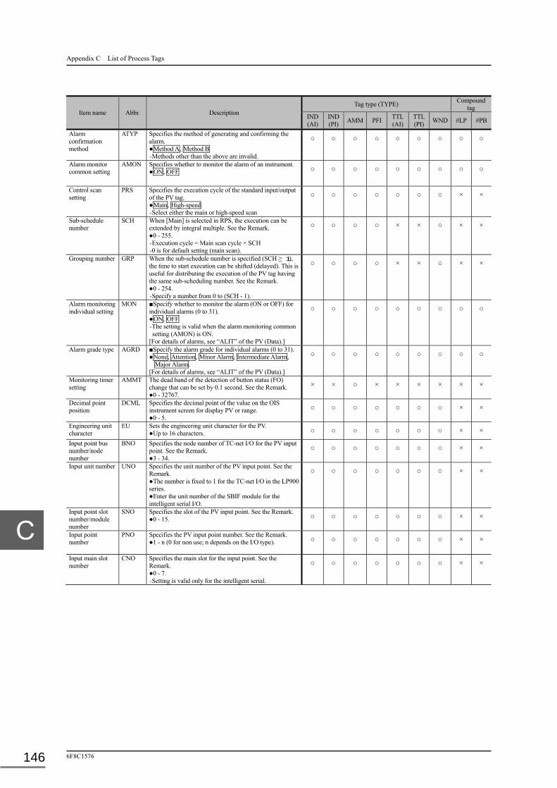
Appendix C List of Process Tags
6F8C1576 146
Item name Abbr. Description Tag type (TYPE) Compound
tag IND (AI)
IND (PI) AMM PFI TTL
(AI) TTL (PI) WND #LP #PB
Alarm confirmation method
ATYP Specifies the method of generating and confirming the alarm. ●Method A, Method B ・Methods other than the above are invalid.
○ ○ ○ ○ ○ ○ ○ ○ ○
Alarm monitor common setting
AMON Specifies whether to monitor the alarm of an instrument. ●ON, OFF ○ ○ ○ ○ ○ ○ ○ ○ ○
Control scan setting
PRS Specifies the execution cycle of the standard input/output of the PV tag. ●Main, High-speed ・Select either the main or high-speed scan
○ ○ ○ ○ ○ ○ ○ × ×
Sub-schedule number
SCH When [Main] is selected in RPS, the execution can be extended by integral multiple. See the Remark. ●0 - 255. ・Execution cycle = Main scan cycle × SCH ・0 is for default setting (main scan).
○ ○ ○ ○ × × ○ × ×
Grouping number GRP When the sub-schedule number is specified (SCH ≥ 1), the time to start execution can be shifted (delayed). This is useful for distributing the execution of the PV tag having the same sub-scheduling number. See the Remark. ●0 - 254. ・Specify a number from 0 to (SCH - 1).
○ ○ ○ ○ × × ○ × ×
Alarm monitoring individual setting
MON ■Specify whether to monitor the alarm (ON or OFF) for individual alarms (0 to 31). ●ON, OFF ・The setting is valid when the alarm monitoring common setting (AMON) is ON.
[For details of alarms, see “ALIT” of the PV (Data).]
○ ○ ○ ○ ○ ○ ○ ○ ○
Alarm grade type AGRD ■Specify the alarm grade for individual alarms (0 to 31). ●None, Attention, Minor Alarm, Intermediate Alarm,
Major Alarm. [For details of alarms, see “ALIT” of the PV (Data).]
○ ○ ○ ○ ○ ○ ○ ○ ○
Monitoring timer setting
AMMT
The dead band of the detection of button status (FO) change that can be set by 0.1 second. See the Remark. ●0 - 32767.
× × ○ × × × × × ×
Decimal point position
DCML Specifies the decimal point of the value on the OIS instrument screen for display PV or range. ●0 - 5.
○ ○ ○ ○ ○ ○ ○ × ×
Engineering unit character
EU Sets the engineering unit character for the PV. ●Up to 16 characters. ○ ○ ○ ○ ○ ○ ○ × ×
Input point bus number/node number
BNO Specifies the node number of TC-net I/O for the PV input point. See the Remark. ●3 - 34.
○ ○ ○ ○ ○ ○ ○ × ×
Input unit number UNO Specifies the unit number of the PV input point. See the Remark. ●The number is fixed to 1 for the TC-net I/O in the LP900 series. ●Enter the unit number of the SBIF module for the intelligent serial I/O.
○ ○ ○ ○ ○ ○ ○ × ×
Input point slot number/module number
SNO Specifies the slot of the PV input point. See the Remark. ●0 - 15. ○ ○ ○ ○ ○ ○ ○ × ×
Input point number
PNO Specifies the PV input point number. See the Remark. ●1 - n (0 for non use; n depends on the I/O type). ○ ○ ○ ○ ○ ○ ○ × ×
Input main slot number
CNO Specifies the main slot for the input point. See the Remark. ●0 - 7. ・Setting is valid only for the intelligent serial.
○ ○ ○ ○ ○ ○ ○ × ×

C.1 PV (Indicator)
Unified Controller nv series type2 light Functional Manual 147
Remark
・ The sub-scheduling (SCH) and grouping (GRP) are based on the same concept with the sub-scheduling and grouping of the program. See Chapter 3 Tasks and Program, 3.3.5 Sub-scheduling and Grouping for the principle of operation and setting.
・ The monitoring time value (AMMT) is set with a combination of the start button PB number (PBNO) and start button number (FONO). These two numbers can be set with the PV tag parameters.
< Example > When PBNO = 1, FONO = 8 and AMMT = 100, alarm processing is not performed for 10 seconds after PB[1].F08 output changes.
・ If the detection of PV I/O error (PDE) is not necessary, do not set the input point (BNO/UNO/SNO/PNO/CNO).
・ The meaning and range of BNO/UNO/SNO/PNO/CNO depend on the I/O module type. For details, see the table below.
IOM
ATOM
TC-net I/O (5),
LP900(6), Special (7)
FF811(8) Intelligent serial (1)
F type serial (4)
CNO Main slot number (0) Main slot number (2 - 7)
BNO NX-I/O node number (3 - 34)
HSE number
(1 - 7)
Bus number (1 - 4)
UNO Unit number (1) System number
(1 - 4)
Unit number(1 - 15)
SNO Module number (0 - 15) Device number
(1 - 32)
Module number
(1 - 14)
Module number
(1 - 4)
PNO Point number
(1 - 64)
Point number
(1 - 8)
Point number
(1 - 32)
Point number
(1 - 32)
Note
When two SB812s are mounted, the bus number in tag registration is determined by the slot.
< Example > SB812 in the slot with a small slot number (left slot): Bus 1, bus 2. SB812 in the slot with a larger slot number (right slot): Bus 3, bus 4.
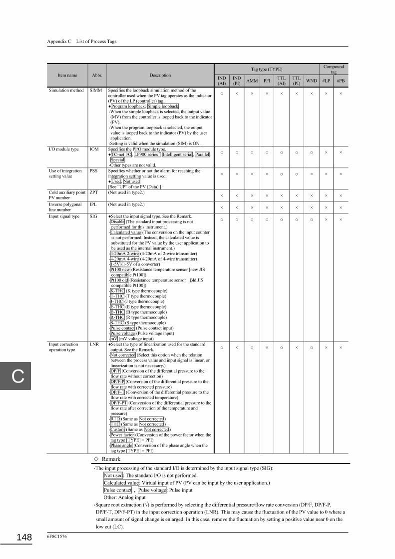
Appendix C List of Process Tags
6F8C1576 148
Item name Abbr. Description Tag type (TYPE) Compound
tag IND (AI)
IND (PI) AMM PFI TTL
(AI) TTL (PI) WND #LP #PB
Simulation method SIMM Specifies the loopback simulation method of the controller used when the PV tag operates as the indicator (PV) of the LP (controller) tag. ●Program loopback, Simple loopback ・When the simple loopback is selected, the output value (MV) from the controller is looped back to the indicator (PV).
・When the program loopback is selected, the output value is looped back to the indicator (PV) by the user application.
・Setting is valid when the simulation (SIM) is ON.
○ × × × × × × × ×
I/O module type IOM Specifies the PI/O module type. ●TC-net I/O, LP900 series ゙, Intelligent serial, Parallel,
Special. ・Other types are not valid.
○ ○ ○ ○ ○ ○ ○ × ×
Use of integration setting value
PSS Specifies whether or not the alarm for reaching the integration setting value is used. ●Used, Not used [See “UP” of the PV (Data).]
× × × × ○ ○ × × ×
Cold auxiliary point PV number
ZPT (Not used in type2.) × × × × × × × × ×
Inverse polygonal line number
IPL (Not used in type2.) × × × × × × × × ×
Input signal type SIG ●Select the input signal type. See the Remark. ・Disable (The standard input processing is not
performed for this instrument.) ・Calculated value (The conversion on the input counter
is not performed. Instead, the calculated value is substituted for the PV value by the user application to be used as the internal instrument.)
・4-20mA 2-wire (4-20mA of 2-wire transmitter) ・4-20mA 4-wire (4-20mA of 4-wire transmitter) ・1-5V (1-5V of a converter) ・Pt100 new (Resistance temperature sensor [new JIS
compatible Pt100]) ・Pt100 old (Resistance temperature sensor [old JIS
compatible Pt100]) ・K-THC (K type thermocouple) ・T-THC (T type thermocouple) ・J-THC (J type thermocouple) ・E-THC (E type thermocouple) ・B-THC (B type thermocouple) ・R-THC (R type thermocouple) ・S-THC (S type thermocouple) ・Pulse contact (Pulse contact input) ・Pulse voltage (Pulse voltage input) ・mV (mV voltage input)
○ ○ ○ ○ ○ ○ ○ × ×
Input correction operation type
LNR ●Select the type of linearization used for the standard output. See the Remark.
・Not corrected (Select this option when the relation between the process value and input signal is linear, or linearization is not necessary.)
・DP/F (Conversion of the differential pressure to the flow rate without correction)
・DP/F-P (Conversion of the differential pressure to the flow rate with corrected pressure)
・DP/F-T (Conversion of the differential pressure to the flow rate with corrected temperature)
・DP/F-PT (Conversion of the differential pressure to the flow rate after correction of the temperature and pressure)
・RTD (Same as Not corrected) ・THC (Same as Not corrected) ・Custom (Same as Not corrected) ・Power factor (Conversion of the power factor when the tag type [TYPE] = PFI)
・Phase angle (Conversion of the phase angle when the tag type [TYPE] = PFI)
○ × ○ × ○ × ○ × ×
Remark
・The input processing of the standard I/O is determined by the input signal type (SIG): Not used: The standard I/O is not performed. Calculated value: Virtual input of PV (PV can be input by the user application.) Pulse contact, Pulse voltage: Pulse input Other: Analog input
・Square root extraction (√) is performed by selecting the differential pressure/flow rate conversion (DP/F, DP/F-P, DP/F-T, DP/F-PT) in the input correction operation (LNR). This may cause the fluctuation of the PV value to 0 where a small amount of signal change is enlarged. In this case, remove the fluctuation by setting a positive value near 0 on the low cut (LC).

C.1 PV (Indicator)
Unified Controller nv series type2 light Functional Manual 149
Item name Abbr. Description Tag type (TYPE) Compound
tag IND (AI)
IND (PI) AMM PFI TTL
(AI) TTL (PI) WND #LP #PB
Input point variable name
PVA ●Specify the PV input point address. ・The input point variable name (PVA) is for registering the destination of input data, and usually the I/O module and point number are directly registered, but the direct notation of the EA number and word number is also available. For the direct notation, see Chapter 4 Variables, 4.15 Direct Notation of Variables.
○ ○ ○ ○ ○ ○ ○ × ×
Input count upper limit (double length)
DCH Sets the input counter value equivalent to the upper limit of instrument range (RH). ●DCH > Input counter lower limit (DCL)
○ × ○ ○ ○ × ○ × ×
Input count lower limit (double length)
DCL
Sets the input counter value equivalent to the lower limit of instrument range (RL). ●DCL < Input counter upper limit (DCH)
○ × ○ ○ ○ × ○ × ×
Low cut LC ●-1 ≤ LC ≤ 10 ・Instantaneous value = 0% when Instantaneous value ≤ LC ・A negative value is invalid.
○ × ○ × × × ○ × ×
Filter coefficient FT ● 0 ≤ FT < 1 ・The primary low-pass filter coefficient (FT) is given by:
Output = Input (1 - FT) + Previous output FT As the above equation suggests, FT removes fluctuation more vigorously as the value is increased.
○ × ○ ○ × × ○ × ×
Instrument range upper limit [EU]
RH Registers the upper limit of indicator (real engineering value). See the Note. ●Instrument range lower limit (RL) < RH
○ ○ ○ ○ ○ ○ ○ × ×
Instrument range lower limit [EU]
RL Registers the lower limit of indicator (real engineering value). See the Note. ●Instrument range upper limit (RH) > RL
○ ○ ○ ○ ○ ○ ○ × ×
PV alarm upper-upper limit [EU]
PHH Registers the upper-upper limit for generating PV alarm (a real engineering value). ○ ○ ○ ○ × × ○ × ×
PV alarm upper limit [EU]
PH Registers the upper limit for generating PV alarm (a real engineering value). ○ ○ ○ ○ × × ○ × ×
PV alarm lower limit [EU]
PL Registers the lower limit for generating PV alarm (a real engineering value). ○ ○ ○ ○ × × ○ × ×
PV alarm lower-lower limit [EU]
PLL Registers the lower-lower limit for generating PV alarm (a real engineering value). ○ ○ ○ ○ × × ○ × ×
PV alarm upper/lower limit dead band [EU]
PVB Registers the dead band of upper/lower limit (a real engineering value). ・The upper limit alarm is generated when PV > PH, and reset when PV ≤ PH - PVB (the same applies to the upper-upper limit alarm).
・The lower limit alarm is generated when PV < PL, and reset when PV ≥ PL + PVB (the same applies to the lower-lower alarm).
○ ○ ○ ○ × × ○ × ×
Note
・Note the following when changing the instrument range (RH/RL) value: (1) When RH = RL, the PVC value is not updated and the last data remains to be stored. When RH ≠ RL, the PVC is
reset to the correct data. (2) When the active system is switched in the duplex system while RH = RL, The PVC value remains to be stored. Change the
setting to RH ≠ RL in the following procedure: i) Set 0 on the filter coefficient (FT). ii) Set the instrument range to RH ≠ RL. iii) Set the filter coefficient (FT) to the original value.
(3) Use the procedure in (2) to change the instrument range from RH = RL to RH ≠ RL in the simulation (SIM =
ON).

Appendix C List of Process Tags
6F8C1576 150
Item name Abbr. Description Tag type (TYPE) Compound
tag IND (AI)
IND (PI) AMM PFI TTL
(AI) TTL (PI) WND #LP #PB
PV change rate alarm [EU/S]
DPL Registers the value for generating the PV change rate alarm is generated. ○ ○ ○ ○ × × ○ × ×
PV change rate alarm dead band [EU/S]
DPB Registers the dead band of change rate alarm: ・The change rate alarm (PVD) is generated when ABS (dPV) > DPL × Scan cycle.
・The alarm is reset when ABS (dPV) ≤ (DPL-DPB) × Scan cycle.
Where dPV is the PV change/scan, and ABS (dPV) is its absolute value.
○ ○ ○ ○ × × ○ × ×
PV number for temperature correction
TM Registers the PV tag number for the input point indicating the measured temperature for correcting the temperature in the process value (e.g. gas flow rate). See the Remark. ●1 - 1024 (0 for no registration)
○ × ○ × ○ × ○ × ×
PV number for pressure correction
PM Registers the PV tag number for the input point indicating the measured pressure for correcting the pressure in the process value (e.g. gas flow rate). See the Remark. ●1 - 1024 (0 for no registration)
○ × ○ × ○ × ○ × ×
Temperature correcting design temperature
TDG Registers the reference design temperature based on which the temperature in the process value (e.g. gas flow rate) is corrected. See the Remark.
○ × ○ × ○ × ○ × ×
Pressure correcting design pressure
PDG Registers the design pressure based on which the pressure in the process value (e.g. gas flow rate) is corrected. See the Remark.
○ × ○ × ○ × ○ × ×
PV error processing type
PRD ●Select the option for setting PRE (PV processing error) when an error occurs in the PV signal source:
・Sensor error OR (Set with an error in own sensor, or sensor for correcting the temperature/pressure)
・Main sensor error (Set with an error in own sensor, not sensors for correction)
・No sensor error (Sensor errors are invalidated) [See “PRE” of the PV (Data).]
○ ○ ○ ○ ○ ○ ○ × ×
Integration input PV number
SPV Registers the PV tag number for the PV value subject to analog integration. ●1 - 1024 (0 for no registration) ・Both the instantaneous and integration values are obtained from the flow rate signal. The instantaneous value is the PV of the flow rate signal containing the actual input value, and the PV value is entered in the integrating instrument to obtain the integrated value.
× × × × ○ × × × ×
Remark
・Temperature/pressure correction operation differs depending on the selected correction unit system for the module parameter as shown below.
(1) The correction coefficient in SI units Temperature correction [ºC]: A = TDG + 273.15
B = [PV of correction input point (TM)] + 273.15 Pressure correction [KPa]: C = PDG + 101.3
D = [PV of correction input point (PM)] + 101.3 (2) The correction coefficient in yard-pound system
Temperature correction [ºF]: A = TDG + 459.67 B = [PV of correction input point (TM)] + 459.67
Pressure correction [PSI]: C = PDG + 14.70 D = [PV of correction input point (PM)] + 14.70
Conversion of the temperature/pressure correction and differential pressure/flow rate is as follows:
Output = Input x (A/B) x (D/C) x 10
[For setting the unit system, see Chapter 7 nV-Tool Support Function, 7.1.5 Others and Ethernet.]

C.1 PV (Indicator)
Unified Controller nv series type2 light Functional Manual 151
Item name Abbr. Description Tag type (TYPE) Compound
tag IND (AI)
IND (PI) AMM PFI TTL
(AI) TTL (PI) WND #LP #PB
Pulse weight coefficient
PU Registers the processed quantity equivalent to one pulse. See the Remark. × ○ × × × ○ × × ×
Time conversion coefficient
T Specifies the unit of time for the PI instantaneous value and analog integration. See the Remark. ●None (0), Second (1), Minute (60), Hour (3600)
× ○ × × ○ × × × ×
Unit conversion coefficient
K Unit conversion coefficient for the process value PV. × ○ × × ○ ○ × × ×
Correction coefficient
D A correction coefficient operating as the conversion coefficient similar to unit conversion coefficient K. See the Remark.
× ○ × × ○ ○ × × ×
Integration upper limit
MAX ●Set the maximum value of integration value for PV. ・The quantity that exceeds the set value is defined as the PV value from which the integration starts in the next cycle. See the Remark.
× × × × ○ ○ × × ×
Integration setting value
PSET [See Integration setting value reached (UP) of the PV (Data).] × × × × ○ ○ × × ×
Start button number FONO Sets the button number for detecting the button status (FO) change. ●1 - 8 (0 for no setting) ・This parameter is used with the monitoring timer (AMMT).
× × ○ × × × × × ×
Start button PB number
PBNO Sets the relevant PB number for detecting the button status (FO) change. ●1 - 1024 (0 for no setting) ・This parameter is used with the monitoring timer (AMMT).
× × ○ × × × × × ×
PV split range position [EU]
SPLT Sets the position of the base point of the split range in the bar graph for the PV value in the OIS split range. ○ ○ ○ × × × × × ×
PV indicator position PVPT Sets the initial value of the indicator of a bar graph displayed on the OIS for indicating the PV value. ○ ○ ○ × × × × × ×
Integration change rate setting value [EU/time]
DMAX The value at which the integration change rate alarm is generated. [See “TTE” of the PV (Data).]
× × × × ○ ○ × × ×
Polygonal line number
PLN (Not used in type2.) × × × × × × × × ×
Power factor signal direction
SGDR Selects the direction of the power factor signal. ●Forward, Inverse ・Specify [Inverse] for inverse processing (inverted to 0 - 100% if the normalized input value is 100 - 0%).
× × × ○ × × × × ×
Lead/lag display setting
PDSP Selects the display direction of the power factor bar graph on the OIS. ●Lead-lag, Lag-lead
× × × ○ × × × × ×
Input device name SENS Sets the identification name of the tag indicating the signal source (e.g. sensor, transmitter). ●Up to 16 characters
× × × × × × × × ×
Remark
・The PU, T, K and D values are used to find the following process values (PV): ・Analog integration value
Integration value = (Previous integration value) + (Current instantaneous value) D K (Scan time) / T
・Pulse integration value Integration value = (Previous integration value) + (Pulse difference count) PU D K
・Pulse instantaneous value Instantaneous value = (Pulse difference count) × PU × D × K × T
When setting coefficients in the above equations, note that the real number arithmetic accuracy in the standard input/output processing is five to six digits in decimal.
・The integration accuracy becomes worse as the integrated PV is closer to the maximum integration value (MAX). If the accuracy is degraded, change the setting as follows: (1) Decrease the maximum integration value (MAX), or (2) Increase the number of integrations (PU, K and D) in a cycle.
When setting the parameters (PU, K, D), note that the accuracy of real number operation in standard output processing is 5 to 6 digits in decimal.

Appendix C List of Process Tags
6F8C1576 152
Item name Abbr. Description Tag type (TYPE) Compound
tag IND (AI)
IND (PI) AMM PFI TTL
(AI) TTL (PI) WND #LP #PB
Calm status V0 Sets the wind speed for calm status and inverse wind. [See “DRC” of the PV (Data).] × × × × × × ○ × ×
Wind direction PV number
PVP Specifies the PV number converted to the wind direction value. ●1 - 1024 (0 for no registration)
× × × × × × ○ × ×
PV lower limit sensor error suppress setting
UIL Sets the suppression of the PV lower limit alarm. ●ON, OFF ・Select ON to disable the PV lower limit alarm (PVIL). ・The PV retains the last value when an sensor error occurs.
○ × ○ ○ × × ○ × ×
PV upper limit sensor error suppress setting
UIH Sets the suppression of the PV upper limit sensor alarm. ●ON, OFF ・ON for disabling the PV upper limit sensor alarm (PVIH) ・The PV retains the last value when a sensor error occurs.
○ × ○ ○ × × ○ × ×
PV/PVC direct connection
DIC ●Select whether to correct the PV value by the user application. ・PV </> PVC (PVC is corrected by the user application and stored in the PV.)
・PV = PVC (PV is not corrected by the user application.)
○ × ○ ○ × × ○ × ×
Update during sensor error
PVIR Specifies whether or not the PV is updated when PVIH or PVIL takes place. ●NO, YES
○ × ○ ○ ○ × ○ × ×
Unipolar/bipolar setting
UBS Set the count range polarity of the AI module. ●BIPOLAR, UNIPOLAR ○ × ○ ○ ○ × ○ × ×
Graduation division number
DVRM <For special use. Not available in type2.> × × × × × × × × ×
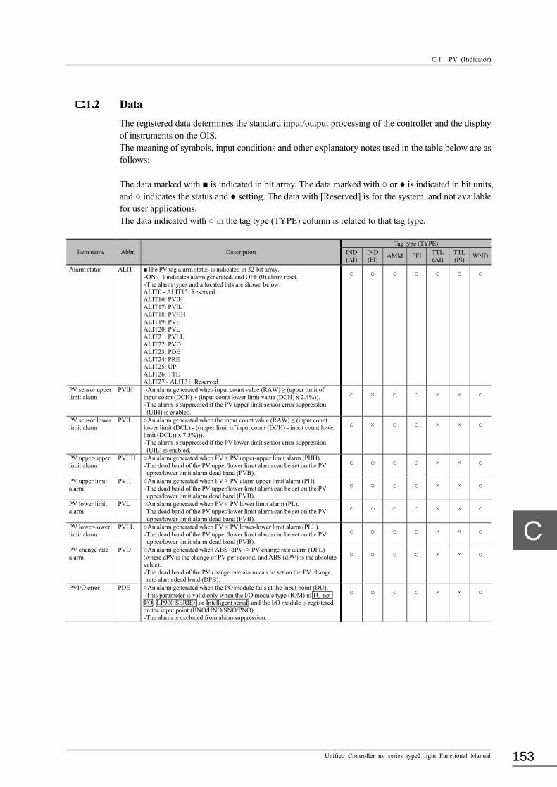
C.1 PV (Indicator)
Unified Controller nv series type2 light Functional Manual 153
C.1.2 Data
The registered data determines the standard input/output processing of the controller and the display of instruments on the OIS. The meaning of symbols, input conditions and other explanatory notes used in the table below are as follows: The data marked with ■ is indicated in bit array. The data marked with ○ or ● is indicated in bit units, and ○ indicates the status and ● setting. The data with [Reserved] is for the system, and not available for user applications. The data indicated with ○ in the tag type (TYPE) column is related to that tag type.
Item name Abbr. Description Tag type (TYPE)
IND (AI)
IND (PI) AMM PFI TTL
(AI) TTL (PI) WND
Alarm status ALIT ■The PV tag alarm status is indicated in 32-bit array. ・ON (1) indicates alarm generated, and OFF (0) alarm reset. ・The alarm types and allocated bits are shown below. ALIT0 - ALIT15: Reserved ALIT16: PVIH ALIT17: PVIL ALIT18: PVHH ALIT19: PVH ALIT20: PVL ALIT21: PVLL ALIT22: PVD ALIT23: PDE ALIT24: PRE ALIT25: UP ALIT26: TTE ALIT27 - ALIT31: Reserved
○ ○ ○ ○ ○ ○ ○
PV sensor upper limit alarm
PVIH ○An alarm generated when input count value (RAW) ≥ (upper limit of input count (DCH) + (input count lower limit value (DCH) x 2.4%)). ・The alarm is suppressed if the PV upper limit sensor error suppression (UIH) is enabled.
○ × ○ ○ × × ○
PV sensor lower limit alarm
PVIL ○An alarm generated when the input count value (RAW) ≤ (input count lower limit (DCL) - ((upper limit of input count (DCH) - input count lower limit (DCL)) x 7.5%))). ・The alarm is suppressed if the PV lower limit sensor error suppression (UIL) is enabled.
○ × ○ ○ × × ○
PV upper-upper limit alarm
PVHH ○An alarm generated when PV > PV upper-upper limit alarm (PHH). ・The dead band of the PV upper/lower limit alarm can be set on the PV upper/lower limit alarm dead band (PVB).
○ ○ ○ ○ × × ○
PV upper limit alarm
PVH ○An alarm generated when PV > PV alarm upper limit alarm (PH). ・The dead band of the PV upper/lower limit alarm can be set on the PV upper/lower limit alarm dead band (PVB).
○ ○ ○ ○ × × ○
PV lower limit alarm
PVL ○An alarm generated when PV < PV lower limit alarm (PL). ・The dead band of the PV upper/lower limit alarm can be set on the PV upper/lower limit alarm dead band (PVB).
○ ○ ○ ○ × × ○
PV lower-lower limit alarm
PVLL ○An alarm generated when PV < PV lower-lower limit alarm (PLL). ・The dead band of the PV upper/lower limit alarm can be set on the PV upper/lower limit alarm dead band (PVB).
○ ○ ○ ○ × × ○
PV change rate alarm
PVD ○An alarm generated when ABS (dPV) > PV change rate alarm (DPL) (where dPV is the change of PV per second, and ABS (dPV) is the absolute value). ・The dead band of the PV change rate alarm can be set on the PV change rate alarm dead band (DPB).
○ ○ ○ ○ × × ○
PVI/O error PDE ○An alarm generated when the I/O module fails at the input point (DU). ・This parameter is valid only when the I/O module type (IOM) is TC-net I/O, LP900 SERIES or Intelligent serial, and the I/O module is registered on the input point (BNO/UNO/SNO/PNO). ・The alarm is excluded from alarm suppression.
○ ○ ○ ○ × × ○

Appendix C List of Process Tags
6F8C1576 154
Item name Abbr. Description Tag type (TYPE)
IND (AI)
IND (PI) AMM PFI TTL
(AI) TTL (PI) WND
PV processing error PRE ○An alarm generated when a sensor error or PV error occurs. ・Alarm generation conditions:
(1) PV error processing type (PRD) = Sensor error OR ・Sensor error (PDE) or PV error (PVIH/PVIL) ・PV processing error (PRE) at the temperature correction input point (TM) or pressure correction input point (PM)
(2) PV error processing type (PRD) = Main sensor error ・PV error (PVIH or PVIL)
[For PRD, TM and PM, see the PV (Parameters).]
○ ○ ○ ○ × × ○
Integration setting value reached
UP ○An alarm generated when PV > Integration setting value (PSET). ・The alarm is valid only when the use of integration setting value (PSS) = Used. [For PSS and PSET, see the PV (Parameters).]
× × × × ○ ○ ×
Integration change rate alarm
TTE ○An alarm generated when the amount of change (ABS (dPV)) > (Integration change rate setting value (DMAX)/3600). (Where ABS (dPV) is the absolute value of the amount of change of PV per second.) ・Integration is stopped while the alarm is generation (TTE = ON). ・The alarm is not generated when the integration change rate setting value (DMAX) = 0.
[For DMAX, see the PV (Parameters).]
× × × × ○ ○ ×
Alarm display status STIT ■The PV tag alarm status is displayed (on the OIS Point screen after confirmation) in 32-bit array. [See “ALIT” for the alarm types and associating bits.]
○ ○ ○ ○ ○ ○ ○
Alarm confirmation status
FLIT ■The PV tag confirmation status (alarm flickering display status on the OIS Point screen) is displayed in 32-bit array. [See “ALIT” for the alarm types and associating bits.]
○ ○ ○ ○ ○ ○ ○
PV status STS ■The PV tag related status is displayed in 32-bit array. ・Status and associating bits 0 to 31 are shown below. STS0 - STS15: Reserved STS4: MSR STS5: WAT STS6: TST STS7: PRF STS8: TRC STS9: ZER STS10 - STS14: Reserved STS15: MHLD STS16: SCN STS17: SIM STS18: SPR STS19: BSIM STS20: RCNF STS21: RLO STS22: RST STS23 - STS28: Reserved STS29: SPR1 STS30: HLD STS31: Reserved
○ ○ ○ ○ ○ ○ ○
Measurement mode MSR ○<For special use. Not used in type2.> × × × × × × × Wait mode WAT ○<For special use. Not used in type2.> × × × × × × × Test mode TST ○<For special use. Not used in type2.> × × × × × × × Configuration mode PRF ○<For special use. Not used in type2.> × × × × × × × Tracking TRC ○<Status not used in type2.> × × × × × × × Zero adjustment mode ZER ○<For special use. Not used in type2.> × × × × × × × Input hold MHLD ○<Status not used in type2.> × × × × × × × Scan setting SCN Sets the update of the present value (PV).
●ON, OFF ・“ON” for not updating the PV (Scan On) ・“OFF” for updating the PV (Scan Off) The setting is indicated on the OIS Instrument screen.
○ ○ ○ ○ ○ ○ ○

C.1 PV (Indicator)
Unified Controller nv series type2 light Functional Manual 155
Item name Abbr. Description Tag type (TYPE)
IND (AI)
IND (PI) AMM PFI TTL
(AI) TTL (PI) WND
Simulation setting SIM Entry into simulation ●ON, OFF ・ON for entering simulation input value (DSIW) ・OFF for entering real data from the I/O module or controller variable set on the input point variable name (PVA)
○ × ○ ○ ○ ○ ○
Alarm suppress setting
SPR Specifies the suppression of alarms. ●ON, OFF ・When (SPR = ON) and (SPR1 = OFF), all alarms (PVIH, PVIL, PVHH, PVH, PVL, PVLL, PVD, PRE, UP, TTE) are suppressed.
・When (SPR = ON) and (SPR1 = ON), all alarms other than PVIH and PVIL are suppressed.
・When (SPR = OFF), all alarms (PVIH, PVIL, PVHH, PVH, PVL, PVLL, PVD, PRE, UP, TTE) are generated.
○ ○ ○ ○ ○ ○ ○
Batch simulation setting
BSIM ○<The status not used type2.> (Not available for user applications.) × × × × × × ×
Alarm confirmation request
RCNF ○The bit status used for the alarm confirmation request from the OIS. ○ ○ ○ ○ ○ ○ ○
LO request RLO ○The bit status used for the LO request from the OIS. ○ ○ ○ ○ ○ ○ ○
Integration reset setting
RST Specifies whether to initialize the integration value for the TTL tag. ●ON, OFF ・“ON” for initializing the integration value for the TTL tag ・“OFF” for starting the integration for the TTL tag.
× × × × ○ ○ ×
Alarm suppress limited setting
SPR1 Specifies whether to enable or disable the alarms for PVIH and PVIL ●ON, OFF ・See the alarm suppress setting (SPR) for how to use this parameter.
○ × ○ ○ × × ○
Input hold HLD Specifies whether to hold or update the PV. ●ON, OFF ・“ON” for holding input to the PV. ・“OFF” for feeding input to the PV. The function similar to Scan Off is available with user applications, but the status is not indicated on the OIS Instrument screen.
○ ○ ○ ○ ○ ○ ○
Present value PV Indicates the input present value in the engineering unit [EU]. See the Remark. ○ ○ ○ ○ ○ ○ ○
Simulation input value (single length)
SINW <Data not used in type2.> ・DSIW (double length) is used for simulation input value. × × × × × × ×
Wind direction DRC The wind direction value (0 - 16) used in the aerovane (WND). ・The DRC value and wind speed (WD) are associated as follows: 0 (north): 0 ≤ WD < 11.25 or 348.75 ≤ WD < 371.25 1 (north north-east): 11.25 ≤ WD < 33.75 or 371.25 ≤ WD < 393.75 2 (north east): 33.75 ≤ WD < 56.25 or 393.75 ≤ WD < 416.25 3 (east north-east): 56.25 ≤ WD < 78.75 or 416.25 ≤ WD < 438.75 4 (east): 78.75 ≤ WD < 101.25 or 438.75 ≤ WD < 461.25 5 (east south-east): 101.25 ≤ WD < 123.75 or 461.25 ≤ WD < 483.75 6 (south east): 123.75 ≤ WD < 146.25 or 483.75 ≤ WD < 506.25 7 (south south-east): 146.25 ≤ WD < 168.75 or 506.25 ≤ WD < 528.75 8 (south): 168.75 ≤ WD < 191.25or 528.75 ≤ WD ≤ 540 9 (south south-west: 191.25 ≤W D < 213.75 10 (south west): 213.75 ≤ WD < 236.25 11 (west south-west): 236.25 ≤ WD < 258.75 12 (west): 258.75 ≤ WD < 281.25 13 (west north west): 281.25 ≤ WD < 303.75 14 (north west): 303.75 ≤ WD < 326.25 15 (north north-west): 326.25 ≤ WD < 348.75 16 (calm): WD < calm status value (V0)
× × × × × × ○
Remark
・The PV can be corrected by the user application by setting PV/PVC direct connection (DIC). PV = PVC for the direct input of PVC into the PV.
Present value (PVC) before correction → Present value (PV) PV </> PVC for the input of PVC corrected by the user application into the PV.
Present value (PVC) before correction → (Correction of PVC by the user application) → Present value (PV)

Appendix C List of Process Tags
6F8C1576 156
Item name Abbr. Description Tag type (TYPE)
IND (AI)
IND (PI) AMM PFI TTL
(AI) TTL (PI) WND
Pre-corrected PV PVC Indicates the PV before correction in the engineering unit [EU]. See the Remark.
○ ○ ○ ○ ○ ○ ○
Raw count value (single length)
RAW <Data not used in type2.> ・DRAW (double length) is used for the simulation input value. × × × × × × ×
Alarm suppress setting
BSPR ■Indicate the alarm suppression status in 32-bit array. ・“ON” for enabling alarm suppress, or OFF for disabling alarm suppress.
[See “ALIT” for the alarm types associated in bits.]
○ ○ ○ ○ ○ ○ ○
PV[%] PVPC Indicates the present value (PV) in percentage [%]. ・The parameter is available for the pulse instantaneous value (TYPE = IND).
○ ○ ○ ○ ○ ○ ○
PVC[%] PVCPC Indicates the present value (PVC) before correction in percentage [%].
・The parameter is available for the pulse instantaneous value (TYPE = IND).
○ ○ ○ ○ ○ ○ ○
Sensor alarm PVI ○Specify the presence of PV sensor upper/lower limit error (PVIH/PVIL). ○ × ○ ○ × × ○
Raw count value (double length)
DRAW Stores the raw count data of PV input. ○ ○ ○ ○ ○ ○ ○
Simulation input value (double length)
DSIW Stores the simulation input value in the raw count (DRAW) when the simulation setting (SIM) is ON. ○ × ○ ○ ○ ○ ○

C.2 LP (Controller)
Unified Controller nv series type2 light Functional Manual 157
C.2 LP (Controller)
The LP (controller) tag registers general data on interface signals for the actuator, standard processing and instrument display types.
C.2.1 Parameters
The input conditions are itemized and each condition begins with ●. Input is allowed only when all conditions are met. The parameter marked with ■ in the description column is indicated in bit array. The parameter marked with ○ in the tag type (TYPE) column is related to that tag type. [The parameters displayed on the OIS are marked with ○ for the application memory.]
Item name Abbr. Description Tag type (TYPE)
PID SPI M/A RS TPI SET BL
Tag number TAG Specifies the identification number given to the instrument. ●Set a number in up to 16 characters including numbers, letters and underbars. Begin the character-string with a letter. ●Use a unique number in the system. ●Do not use the reserved word in the system. Lower and upper case letters are not discriminated. All are treated as upper case letters.
○ ○ ○ ○ ○ ○ ×
Tag name NAME Specifies the name of this instrument. ●Up to 32 characters. ○ ○ ○ ○ ○ ○ ×
Tag type TYPE ●Select the function type of the instrument from those listed below. ・Not used ・PID (PID controller) ・SPI (Sample PI controller) ・M/A (M/A operating equipment) ・RS (Ratio setting equipment) ・TPI (Time proportional PID controller) ・SET (Setting value output) ・BLM (Blend master) ・BLC (Blend controller) ・BMA (Batch quantitative analog meter) ・BMD (Batch quantitative digital meter)
○ ○ ○ ○ ○ ○ ○
Display pattern model number
MDL Specifies the instrument display pattern on the OIS. ●0 - 9. ・Enter 0 for the standard pattern. ・Enter 1 to 9 for the indication pattern created by the user.
○ ○ ○ ○ ○ ○ ×
Signal type number AREA Specifies the instrument signals for grouping in the whole system. ●0 - 63. ○ ○ ○ ○ ○ ○ ×
Automatic screen display number
SCNO Sets the OIS screen automatically selected when an alarm is generated. ●0 - 1024. ・Enter 0 for disabling the automatic display.
○ ○ ○ ○ ○ ○ ×
Operation inhibition LOCK Specifies whether to permit or inhibit operator action when an instrument tag is set on the OIS. ●Permit, Inhibit.
○ ○ ○ ○ ○ ○ ×
Tag color COLR Specifies the tag display color. ●White, Red, Green, Yellow, Blue, Purple, Azure, Black, Light perse,
Subdued orange, Perse, Orange, Brilliant gray, Bright gray, Gray, Deep gray, Dark gray, Perse, Grayish blue, Light gray, Charcoal, Reddish brown , Green tea, Hay, Indigo, Navy-blue, Sage green, Subdued gray, Light green, Subdued white, Subdued greenish yellow, Subdued charcoal.
○ ○ ○ ○ ○ ○ ×
Tag letter SIGN Specifies the character string representing a tag. ●Up to 16 characters ○ ○ ○ ○ ○ ○ ×
Alarm confirmation method
ATYP Specifies the method of generating and confirming the alarm. ●Method A, Method B ・Methods other than the above are invalid.
○ ○ ○ ○ ○ ○ ×
Alarm monitor common setting
AMON Specifies whether to monitor the alarm of an instrument. ●ON, OFF ○ ○ ○ ○ ○ ○ ×
Control scan setting PRS Specifies the execution cycle of the standard input/output of the PV tag. ●Main, High-speed ・Select either the main or high-speed scan
○ ○ ○ ○ ○ ○ ×
Sub-schedule number SCH <Not used in type2.> × × × × × × × Grouping number GRP <Not used in type2.> × × × × × × × Alarm monitoring individual setting
MON ■Specify whether to monitor the alarm (ON or OFF) for individual alarms (0 to 31). ●ON, OFF ・The setting is valid when the alarm monitoring common setting (AMON) is ON.
[For details of alarms, see “ALIT” of the PV (Data).]
○ ○ ○ ○ ○ ○ ×
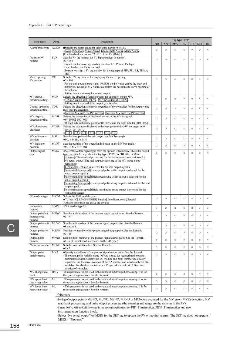
Appendix C List of Process Tags
6F8C1576 158
Item name Abbr. Description
Tag type (TYPE) PID SPI M/A RS TPI SET BL
Alarm grade type AGRD ■Specify the alarm grade for individual alarms (0 to 31). ●None, Attention, Minor Alarm, Intermediate Alarm, Major Alarm. [For details of alarms, see “ALIT” of the PV (Data).]
○ ○ ○ ○ ○ ○ ×
Indicator PV number
PVP Sets the PV tag number for PV input (subject to control). ●0 - 384 ・Do not use the same tag number for other LP , PB and PV tags. ・Enter 0 when the PV is not used. ・Be sure to assign a PV tag number for the tag type of PID, SPI, RS, TPI and SET.
○ ○ ○ ○ ○ ○ ×
Valve opening PV number
VP Sets the PV tag number for displaying the valve opening. ●0 - 384 ・For the pulse output type signal (MSIG), the PV value can be fed back and displayed, instead of MV value, to confirm the position and valve opening of the actuator.
・Setting is not necessary for analog output.
○ ○ ○ × × × ×
MV output direction setting
MDR Selects the direction of analog output for operation mount MV. ●4-20mA output at 0 - 100%、,20-4mA output at 0-100% ・Setting is not required if the output type is pulse.
○ ○ ○ × ○ × ×
Control operation direction setting
CDR Selects the direction arithmetic operation of the controller for the output value (MV) for the deviation. ●Increase MV with SV-PV increase, Decrease MV with SV-PV increase
○ ○ × × ○ × ×
MV display direction setting
MDSP Selects the base point of display direction of the MV bar graph. ●0 - 100%, 100 - 0% ・The left side is the base point for [0 100%] and the right side for [100 - 0%].
○ ○ ○ ○ ○ × ×
MV close/open character
VCHR Selects the character displayed at the base point of the MV bar graph in [0 - 100% (100 - 0%)]. ●C - O, O - C, C - C, O - O, S - O, O - S, S - S
○ ○ ○ ○ ○ × ×
MV split range position
MSPL Sets the base point of the split range type MV bar graph. ●ML ≤ MSPL ≤ MH ○ ○ ○ ○ ○ × ×
MV indicator position
MVPT Sets the position of the operation indicator on the MV bar graph.。 ●ML ≤ MVPT ≤ MH ○ ○ ○ × ○ × ×
Output signal type
MSIG ●Select the output signal type from the options listed below. The pulse output type is available only when the tag type (TYPE) is PID, SPI, or M/A. ・Not used (The standard processing for this instrument is not performed.) ・No actual output (The real output processing of the MV value is not performed)
・4 -20 mA (4 - 20 mA is selected for the real output signal.) ・Pulse width low-speed (Low-speed pulse width output is selected for the actual output signal.)
・Pulse width high-speed (High speed pulse width output is selected for the actual output signal.)
・Pulse string low-speed (Low-speed pulse string output is selected for the real output signal.)
・Pulse string high-speed (High-speed pulse string output is selected for the real output signal.)
○ ○ ○ ○ ○ ○ ×
I/O module type MIOM Selects the PI/O module type. ●TC-net I/O, LP900 SERIES, Parallel, Intelligent serial, Special ・Options other than the above are invalid.
○ ○ ○ ○ ○ ○ ×
Simulation method
SIMM <Not used in type2.> × × × × × × ×
Output point bus number/node number
MBNO Sets the node number of the process signal output point. See the Remark. ●3 - 34 ○ ○ ○ × ○ ○ ×
Output point unit number
MUNO Sets the unit number of the process signal output point. See the Remark. ●Fixed to 1. ○ ○ ○ × ○ ○ ×
Output point slot number
MSNO Sets the slot number of the process signal output point. See the Remark. ●0 - 15 ○ ○ ○ × ○ ○ ×
Output point number
MPNO Sets the point number of the process signal output point. See the Remark. ●1 - n (0 for not used. n depends on the I/O type.) ○ ○ ○ × ○ ○ ×
Main slot number MCNO Sets the main slot number. See the Remark. ●0 - 7 ○ ○ ○ × ○ ○ ×
Output point variable name
MVA ●Specify the address of the process signal output point. See the Remark. ・The output point variable name (MVA) is used for registering the output destination of data. Usually the I/O module and point number are directly registered, but the direct notation of the EA number and word number is also available. For the direct notation, see Chapter 4 Variable, 4.15 Direction notation of variables.
○ ○ ○ × ○ ○ ×
MV change rate limit
DMV <This parameter is not used in the standard input/output processing. It is for the system application.> See the Remark. ○ ○ ○ ○ ○ × ×
MV upper limit restricting value
MH <This parameter is not used in the standard input/output processing. It is for the system application.> See the Remark. ○ ○ ○ ○ ○ × ×
MV lower limit restricting value
ML <This parameter is not used in the standard input/output processing. It is for the system application.> See the Remark. ○ ○ ○ ○ ○ × ×
Remark
・Setting of output points (MBNO, MUNO, MSNO, MPNO or MCNO) is required for the MV error (MVE) detection, MV read-back processing, and pulse output processing (the meaning and range are the same as in the PV).
・Limits DMV, MH and ML are used in the system applications for PID_P instruction, PIDP_P instruction and new instrumentation function block.
・Select “No actual output” on MSIG for the SET tag to update the PV or monitor alarms. The SET tag does not operate if MSIG = “Not used”

C.2 LP (Controller)
Unified Controller nv series type2 light Functional Manual 159
Item name Abbr. Description Tag type (TYPE)
PID SPI M/A RS TPI SET BL
MV upper limit alarm
MHA Specifies the upper limit of the MV alarm. ○ ○ ○ ○ ○ × ×
MV lower limit alarm
MLA Specifies the lower limit of the MV alarm. ○ ○ ○ ○ ○ × ×
MV alarm dead band
MVB Sets the dead band of the upper/lower limit. ・An upper limit alarm is generated when MV > MHA, and reset when MV ≤ MHA-MVB.
・A lower limit alarm is generated when MV < MLA, and reset when MV ≥ MLA + MVB.
○ ○ ○ ○ ○ × ×
Control stop type CLD Selects the operation of the control stop alarm (CLI) and control mode (MOD). See the Remark. ●CLI/M mode demotion with PV/MV error, User defined CLI
○ ○ ○ ○ ○ × ×
Control mode setting
CMD Selects the operation range of the control mode of the controller. ●Permit, C Mode Inhibit, A Mode Inhibit, M Mode Inhibit, C/A Mode, Inhibit,
C/M Mode Inhibit, A/M Mode Inhibit
○ ○ ○ ○ ○ ○ ×
A mode SV setting SVS Selects whether to permit or inhibit the setting of the SV value (from the OIS) when the controller is in A mode. ●Permit, Inhibit
○ ○ ○ ○ ○ ○ ×
Control cycle DT <Not used in the standard input/output processing. It is for the system application.> See the Remark.
○ × × × ○ × ×
Sample time T0 <Not used in the standard input/output processing. It is for the system application.> See the Remark.
× ○ × × × × ×
Control time T1 <Not used in the standard input/output processing. It is for the system application.> See the Remark.
× ○ × × × × ×
Proportional gain KP <Not used in the standard input/output processing. It is for the system application.> See the Remark.
○ ○ × × ○ × ×
Integral time TI <Not used in the standard input/output processing. It is for the system application.> See the Remark.
○ ○ × × ○ × ×
Differential time TD <Not used in the standard input/output processing. It is for the system application.> See the Remark.
○ × × × × × ×
Differential coefficient (η)
ETA <Not used in the standard input/output processing. It is for the system application.> See the Remark.
○ × × × × × ×
2-degree-of-freedom proportional coefficient (α)
ALP <Not used in the standard input/output processing. It is for the system application.> See the Remark.
○ ○ × × ○ × ×
2-degree-of-freedom integral coefficient (β)
BET <Not used in the standard input/output processing. It is for the system application.> See the Remark.
○ ○ × × ○ × ×
2-degree-of-freedom differential coefficient (γ)
GAM <Not used in the standard input/output processing. It is for the system application.> See the Remark.
○ ○ × × ○ × ×
Deviation gap width
GP <Not used in the standard input/output processing. It is for the system application.> See the Remark.
○ ○ × × ○ × ×
Deviation gap gain GG <Not used in the standard input/output processing. It is for the system application.> See the Remark.
○ ○ × × ○ × ×
Proportional gain GAIN <Not used in the standard input/output processing. It is for the system application.> See the Remark.
× × × ○ × × ×
Proportional bias BIAS <Not used in the standard input/output processing. It is for the system application.> See the Remark.
× × × ○ × × ×
Remark
・The control parameters (CLD, DT, T0, T1, KP, TI, TD, ETA, ALP, BET, GAM, GP, GG, GAIN, BAIS) are used for the system application. The table below shows the range of use.
CLD DT T0 T1 KP TI TD ETA ALP BET GAM GP GG GAIN BAIS PID_P instruction - ○ - - ○ ○ ○ ○ ○ ○ ○ ○ ○ - - PIDP_P instruction - ○ - - ○ ○ ○ ○ ○ ○ ○ ○ ○ - - New instrumentation FB library ○ ○ ○ ○ ○ ○ ○ ○ ○ ○ ○ ○ ○ ○ ○
・The options for the control stop type (CLD) are shown below. (1) CLI/M mode demotion with PV/MV error:
When a PV or MV error is detected in the new instrumentation function block, the control stop alarm (CLI) is set to turn the control mode (MOD) to M mode.
(2) User Defined CLI: The control stop mode (CLI) and control mode (MOD) are defined by the user application.
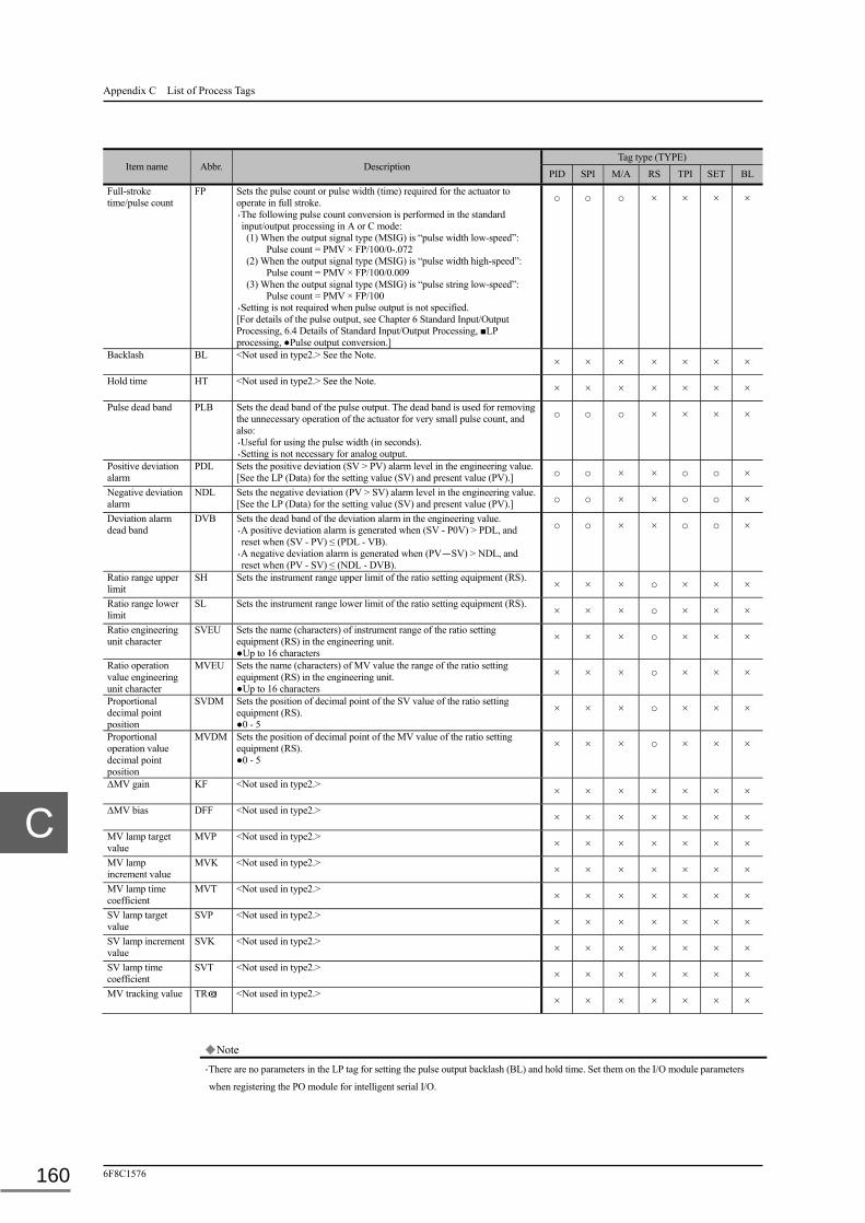
Appendix C List of Process Tags
6F8C1576 160
Item name Abbr. Description Tag type (TYPE)
PID SPI M/A RS TPI SET BL
Full-stroke time/pulse count
FP Sets the pulse count or pulse width (time) required for the actuator to operate in full stroke. ・The following pulse count conversion is performed in the standard input/output processing in A or C mode: (1) When the output signal type (MSIG) is “pulse width low-speed”:
Pulse count = PMV × FP/100/0-.072 (2) When the output signal type (MSIG) is “pulse width high-speed”:
Pulse count = PMV × FP/100/0.009 (3) When the output signal type (MSIG) is “pulse string low-speed”:
Pulse count = PMV × FP/100 ・Setting is not required when pulse output is not specified. [For details of the pulse output, see Chapter 6 Standard Input/Output Processing, 6.4 Details of Standard Input/Output Processing, ■LP processing, ●Pulse output conversion.]
○ ○ ○ × × × ×
Backlash BL <Not used in type2.> See the Note. × × × × × × ×
Hold time HT <Not used in type2.> See the Note. × × × × × × ×
Pulse dead band PLB Sets the dead band of the pulse output. The dead band is used for removing the unnecessary operation of the actuator for very small pulse count, and also: ・Useful for using the pulse width (in seconds). ・Setting is not necessary for analog output.
○ ○ ○ × × × ×
Positive deviation alarm
PDL Sets the positive deviation (SV > PV) alarm level in the engineering value. [See the LP (Data) for the setting value (SV) and present value (PV).] ○ ○ × × ○ ○ ×
Negative deviation alarm
NDL Sets the negative deviation (PV > SV) alarm level in the engineering value. [See the LP (Data) for the setting value (SV) and present value (PV).] ○ ○ × × ○ ○ ×
Deviation alarm dead band
DVB Sets the dead band of the deviation alarm in the engineering value. ・A positive deviation alarm is generated when (SV - P0V) > PDL, and reset when (SV - PV) ≤ (PDL - VB).
・A negative deviation alarm is generated when (PV-SV) > NDL, and reset when (PV - SV) ≤ (NDL - DVB).
○ ○ × × ○ ○ ×
Ratio range upper limit
SH Sets the instrument range upper limit of the ratio setting equipment (RS). × × × ○ × × ×
Ratio range lower limit
SL Sets the instrument range lower limit of the ratio setting equipment (RS). × × × ○ × × ×
Ratio engineering unit character
SVEU Sets the name (characters) of instrument range of the ratio setting equipment (RS) in the engineering unit. ●Up to 16 characters
× × × ○ × × ×
Ratio operation value engineering unit character
MVEU Sets the name (characters) of MV value the range of the ratio setting equipment (RS) in the engineering unit. ●Up to 16 characters
× × × ○ × × ×
Proportional decimal point position
SVDM Sets the position of decimal point of the SV value of the ratio setting equipment (RS). ●0 - 5
× × × ○ × × ×
Proportional operation value decimal point position
MVDM Sets the position of decimal point of the MV value of the ratio setting equipment (RS). ●0 - 5
× × × ○ × × ×
ΔMV gain KF <Not used in type2.> × × × × × × ×
ΔMV bias DFF <Not used in type2.> × × × × × × ×
MV lamp target value
MVP <Not used in type2.> × × × × × × ×
MV lamp increment value
MVK <Not used in type2.> × × × × × × ×
MV lamp time coefficient
MVT <Not used in type2.> × × × × × × ×
SV lamp target value
SVP <Not used in type2.> × × × × × × ×
SV lamp increment value
SVK <Not used in type2.> × × × × × × ×
SV lamp time coefficient
SVT <Not used in type2.> × × × × × × ×
MV tracking value TR@ <Not used in type2.> × × × × × × ×
Note
・There are no parameters in the LP tag for setting the pulse output backlash (BL) and hold time. Set them on the I/O module parameters
when registering the PO module for intelligent serial I/O.

C.2 LP (Controller)
Unified Controller nv series type2 light Functional Manual 161
Item name Abbr. Description Tag type (TYPE)
PID SPI M/A RS TPI SET BL
Output device name ACTS Sets the name (characters) of the adjusting valve connecting the output signal. ●Up to 16 characters
× × × × × × ×
Inching pulse width POIP Sets the pulse width (or string) output during inching (slow) on the OIS Point screen. See the Remark. ●0 - 1500 ・The setting value is used as the pulse output when the pulse inching request (IOPN/ICLS) is ON in RM mode.
・Setting is not necessary for analog output. [For details of the pulse output, see Chapter 6 Standard Input/Output Processing, 6.4 Details of Standard Input/Output Processing, ■LP processing, ●Pulse output conversion.]
○ ○ ○ × × × ×
SV major tracking specification
FS0 <Used in the “new instrumentation FB library - DS type.” ○ ○ × × × × ×
Cascade value type FS1 <Used in the “new instrumentation FB library - DS type.” ○ ○ × × × × ×
Dead time [min] (for model driving PID)
MDT <Used in the “model driving PID FB library.” ○ ○ × × × × ×
PD compensator gain (for model driving PID)
MKF <Used in the “model driving PID FB library.” ○ ○ × × × × ×
PD compensator differential time [min] (for model driving PID)
MTF <Used in the “model driving PID FB library.” ○ ○ × × × × ×
MV direction character display
VMHC < Not used in type. It is for special applications.> × × × × × × ×
Batch number BLP (Data for user applications) × × × × × × ○

Appendix C List of Process Tags
6F8C1576 162
C.2.2 Data
The registered data determines the standard input/output processing of the controller and the display of instruments on the OIS. The meaning of symbols, input conditions and other explanatory notes used in the table below are as follows: The data marked with ■ is indicated in bit array. The data marked with ○ or ● is indicated in bit units, and ○ indicates the status and ● setting. The data indicated with ○ in the tag type (TYPE) column is related to that tag type.
Item name Abbr. Description Tag type (TYPE)
PID SPI M/A RS TPI SET BL
Alarm status ALIT ■The LP tag alarm status is indicated in 32-bit array. ・“ON” for alarm generated, and “OFF” for alarm reset. ・When the indicator PV number (PVP) is registered, ALIT16 - ALIT31 of the PV tag are overwritten with ALIT16 - ALIT31 of this tag.
・The alarm types and allocated bits (0 - 31) are shown below. ALIT0: CLI ALIT1: MVE ALIT2: MVH ALIT3: MVL ALIT4: PDV ALIT5:NDV ALIT6: VPI ALIT7 - ALIT15: Reserved ALIT16: PVIH ALIT17: PVIL ALIT18: PVHH ALIT19: PVH ALIT20: PVL ALIT21: PVLL ALIT22: PVD ALIT23: PDE ALIT24: PRE ALIT25: UP ALIT26: TTE ALIT27 - ALIT31: Reserved
○ ○ ○ ○ ○ ○ ×
Control stop alarm CLI ○An alarm for control stop. [This bit can be operated by the user application. For details, see “CLS” of the LP (Parameter).]
○ ○ ○ ○ ○ × ×
MV error MVE ○An alarm generated when a read-back error (RB) occurs in the I/O module registered for the output point. See the Note. Alarm generation is valid only when the I/O module type (MIOM) is TC-net I/O, LP900 Series or Intelligent Serial.
○ ○ ○ × ○ × ×
MV upper limit alarm
MVH ○An alarm generated when MV > MV upper limit alarm (MHA). ○ ○ ○ ○ ○ × ×
MV lower limit alarm
MVL ○An alarm generated when MV < MV alarm lower limit (MLA). ○ ○ ○ ○ ○ × ×
Positive deviation alarm
PDV ○An alarm generated when the positive deviation (SV - PV) > the positive deviation alarm (PDL). ○ ○ × ○ ○ ○ ×
Negative deviation alarm
NDV ○An alarm generated when the negative deviation (PV - SV) < the negative alarm (NDL). ○ ○ × ○ ○ ○ ×
Valve open error VPI ○An alarm generated when a sensor error occurs in the AI card specified in the valve opening PV number (VP). ・Alarm generation is valid only when the output signal type (MSIG) is pulse.
○ ○ ○ × × × ×
Integrated deviation 1 alarm
SDV1 (Data for user applications) × × × × × × ○
Integrated deviation 2 alarm
SDV2 (Data for user applications) × × × × × × ○
PV sensor upper limit alarm
PVIH ○[See “PVIH” of the PV (Data).] ○ ○ ○ ○ ○ ○ ×
PV sensor lower limit alarm
PVIL ○[See “PVIL” of the PV (Data).] ○ ○ ○ ○ ○ ○ ×
PV upper-upper limit alarm
PVHH ○[See “PVHH” of the PV (Data).] ○ ○ ○ ○ ○ ○ ×
PV upper limit alarm
PVH ○[See “PVH” of the PV (Data).] ○ ○ ○ ○ ○ ○ ×
PV lower limit alarm
PVL ○[See “PVL” of the PV (Data).] ○ ○ ○ ○ ○ ○ ×
PV lower-lower limit alarm
PVLL ○[See “PVIH” of the PV (Data).] ○ ○ ○ ○ ○ ○ ×
Note
・The MV error is not reset when it is acknowledged on the OIS. It is reset only when error recovery is performed on the OIS. The MV error (MVE) is excluded from the alarm suppression.

C.2 LP (Controller)
Unified Controller nv series type2 light Functional Manual 163
Item name Abbr. Description Tag type (TYPE)
PID SPI M/A RS TPI SET BL
PV change rate alarm
PVD ○[See “PVD” of the PV (Data).] ○ ○ ○ ○ ○ ○ ×
PVI/O error PDE ○[See “PDE” of the PV (Data).] ○ ○ ○ ○ ○ ○ ×
PV processing error
PRE ○[See “PRE” of the PV (Data).] ○ ○ ○ ○ ○ ○ ×
Integration setting value reached status
UP ○[See “UP” of the PV (Data).] ○ ○ ○ ○ ○ ○ ×
Integration change rate alarm
TTE ○[See “TTE” of the PV (Data).] ○ ○ ○ ○ ○ ○ ×
Leak alarm (for future use)
LEK (Data for user applications) × × × × × × ○
Pulse not reached alarm (for future use)
PNI (Data for user applications) × × × × × × ○
Alarm display status
STIT ■The LP tag alarm status is displayed in 32-bit array on the OIS Point screen after confirmation. [See “ALIT” for the alarm types and associating bits.]
○ ○ ○ ○ ○ ○ ×
Alarm confirmation status
FLIT ■The LP tag confirmation status (alarm flickering display status) is displayed in 32-bit array on the OIS Point screen). [See “ALIT” for the alarm types and associating bits.]
○ ○ ○ ○ ○ ○ ×
Loop status STS ■The LP tag related status is displayed in 32-bit array. ・When the indicator PV number (PVP) is registered (≠0), STS16 - STS31 of the corresponding PV tag are overwritten on STS16 - STS31.
・Status and associating bits 0 to 31 are shown below. STS0: SSV STS1: CSV STS2: SMV STS3: CMV STS4: M STS5: A STS6: C STS7: RM STS8: TRC STS9: Reserved STS10: POR STS1: IOPN STS12: ICLS STS13 - STS15: Reserved STS16: SCN STS17: SIM STS18: SPR STS19: BSIM STS20: RCNF STS21: RLO STS22: RST STS23 - STS28: Reserved STS29: SPR1 STS30: HLD STS31: Reserved
○ ○ ○ ○ ○ ○ ×
SEQ-SV intervention status
SSV ○SEQ-SV intervention status (This bit is turned on and off by the user application.) ○ ○ ○ ○ ○ ○ ×
CMP-SV intervention status
CSV ○CMP-SV intervention status (This bit is turned on and off by the user application.) ○ ○ ○ ○ ○ × ×
SEQ-MV intervention status
SMV ○SEQ-MV intervention status (This bit is turned on and off by the user application.) ○ ○ ○ ○ ○ × ×
CMP-MV intervention status
CMV ○CMP-MV intervention status (This bit is turned on and off by the user application.) ○ ○ ○ ○ ○ × ×
Control mode M/A/ C/RM
○BOOL type data in control mode ・It changes with the control mode (MOD). ○ ○ ○ ○ ○ ○ ×
MV tracking status
TRC ○The MV tracking status (This bit is turned on and off by the user application.) ○ ○ ○ ○ ○ × ×
Pulse output request
POR ○The pulse output request status ○ ○ ○ × × × ×
Pulse inching request (OPEN)
IOPN ○The pulse output inching request (OPEN side) status ○ ○ ○ × × × ×
Pulse inching request (CLOSE)
ICLS ○The pulse output inching request (CLOSE side) status ○ ○ ○ × × × ×
Scan setting SCN ○[See “SCN” of the PV (Data).] ○ ○ ○ ○ ○ ○ ○
Simulation setting SIM ○[See “SIM” of the PV (Data).] ・When SIM is ON, MV output and read-back are not performed. ○ ○ ○ ○ ○ ○ ○
Alarm suppress setting
SPR ○[See “SPR” of the PV (Data).] ・The alarms of the LP tag (MVH, MVL, PDV and NDV) are also included in alarm suppression.
○ ○ ○ ○ ○ ○ ○

Appendix C List of Process Tags
6F8C1576 164
Item name Abbr. Description Tag type (TYPE)
PID SPI M/A RS TPI SET BL
Batch simulation setting
BSIM ○[See “BSIM” of the PV (Data).] ○ ○ ○ ○ ○ ○ ○
Alarm confirmation request
RCNF ○[See “RCNF” of the PV (Data).] ○ ○ ○ ○ ○ ○ ○
LO request RLO ○[See “RLO” of the PV (Data).] ○ ○ ○ ○ ○ ○ ○
Integration reset setting
RST ○[See “RST” of the PV (Data).] ○ ○ ○ ○ ○ ○ ○
Alarm suppress limitation setting
SPR1 ○[See “SPR1” of the PV (Data).] ○ ○ ○ ○ ○ ○ ○
Input hold HLD ○[See “HLD” of the PV (Data).] ○ ○ ○ ○ ○ ○ ○
Present value [EU]
PV Displays the same value with the present value (PV) on the PV tag. [See “PV” of the PV (Data).] ○ ○ ○ ○ ○ ○ ×
Present value [EU]
SV (Data for user applications) ○ ○ ○ ○ ○ ○ ×
Output value [%] MV (Data for user applications) ○ ○ ○ ○ ○ × ×
Control mode MOD Sets the control mode (M = 0, A = 1, C = 2, RM = 3) ・M mode: The output value (MV) is overwritten with the read-back data. ・C/A mode: The output value (MV) set by the user application is output for analog output.
・RM mode: The operator manipulates the output value (MV) from the OIS.
○ ○ ○ ○ ○ ○ ×
Pulse output ΔMV
PMV The “PMV” value is output for pulse output. ○ ○ ○ × × × ×
Raw count value RAW <Data not used in type2.> ・”DRAW” is used in type2.
MV tracking value
TR (Data for user applications) × × × × × × ×
PO user area 1 RPLS (Data for user applications) × × × × × × ×
PO user area 2 POWK (Data for user applications) × × × × × × ×
Alarm mask status
BSPR ■The LP tag alarm suppress status is displayed in 32-bit array. ・“ON” (1) for enabling alarm suppression, or “OFF” (0) for disabling alarm suppression. [See “ALIT” for the alarms and associated bits.]
○ ○ ○ ○ ○ ○ ×
PV[%] PVPC Indicates the same value with the present value of the PV tag (PVPC). [See “PVPC” of the PV (Data).] ○ ○ ○ ○ ○ ○ ×
PVC[%] PVCPC Indicates the same value with the present value of the PV tag before correction (PVCPC). [Status not used in type2. “PVCPC” of the PV (Data).]
○ ○ ○ ○ ○ ○ ×
SV[%] SVPC Indicates the setting value (SV) in percentage [%]. ○ ○ ○ ○ ○ ○ × Sensor alarm PVI ○BOOL type status for indicating the PV sensor lower limit alarm
(PVIL) or PV sensor upper limit alarm (PVIH). ○ ○ ○ ○ ○ ○ ×
Computer flag CMP ○BOOL type status as the CMP-SV intervention status (CSV) or CMP-MV intervention status (CMV). ○ ○ ○ ○ ○ ○ ×
M mode set MCH ○BOOL type status indicating change to M mode. ○ ○ ○ ○ ○ ○ ×
A mode set ACH ○BOOL type status indicating change to A mode. ○ ○ ○ ○ ○ ○ × C mode set CCH ○BOOL type status indicating change to C mode. ○ ○ ○ ○ ○ ○ × Mode change MDCH ○BOOL type status indicating change in control mode. ○ ○ ○ ○ ○ ○ × M/RM mode MRM ○BOOL type status indication M or RM mode. ○ ○ ○ ○ ○ ○ × Deviation alarm DVE ○BOOL type status indicating the generation of a positive deviation
alarm (DV) or negative deviation alarm (NDV). ○ ○ ○ ○ ○ ○ ×
MVOVER ○ ○ ○ ○ ○ ○ ×
Raw count value (double length)
DRAW Indicates the same data with the raw count (RAW) of the PV tag. ・It is valid when the indicator PV number (PVP) is registered. [See “RAW” of the PV (Data).]
○ ○ ○ ○ ○ ○ ×
Batch status BSTS (Data for user applications) × × × × × × ○
Start instruction STA1 (Data for user applications) × × × × × × ○
Stop instruction STP (Data for user applications) × × × × × × ○
Reset instruction RST1 (Data for user applications) × × × × × × ○
End instruction END (Data for user applications) × × × × × × ○

C.2 LP (Controller)
Unified Controller nv series type2 light Functional Manual 165
Item name Abbr. Description Tag type (TYPE)
PID SPI M/A RS TPI SET BL
Main valve output MAIN (Data for user applications) × × × × × × ○
Sub-valve output SUB (Data for user applications) × × × × × × ○
EST end instruction
EST (Data for user applications) × × × × × × ○
Master paging instruction
MPX (Data for user applications) × × × × × × ○
Initializing status INZ (Data for user applications) × × × × × × ○
RUN1 status RUN1 (Data for user applications) × × × × × × ○
RUN2 status RUN2 (Data for user applications) × × × × × × ○
Pre-batch 1 status PRE1 (Data for user applications) × × × × × × ○
Pre-batch 2 status PRE2 (Data for user applications) × × × × × × ○
Hold status HOLD (Data for user applications) × × × × × × ○
End status END1 (Data for user applications) × × × × × × ○
Master paging status
MP (Data for user applications) × × × × × × ○
Integrated PV value
SPVB (Data for user applications) × × × × × × ○
Integration setting value
SSVB (Data for user applications) × × × × × × ○
Total quantity setting value
QT (Data for user applications) × × × × × × ○
Ratio RT (Data for user applications) × × × × × × ○

Appendix C List of Process Tags
6F8C1576 166
C.3 PB (Pushbutton)
The PB tag registers general data on the interface signals for pushbuttons, lamps and other digital devices, standard processing and instrument display.
C.3.1 Parameters
The input conditions are itemized and each condition begins with ●. Input is allowed only when all conditions are met. The parameter marked with ■ in the description column is indicated in bit array. The parameter marked with ○ in the tag type (TYPE) column is related to that tag type.
Item name Abbr. Description
Tag type (TYPE)
SOV MOT MOV PB4 PB8 PB2 2PC BT4 BT8 LP4 LP8
Tag number TAG Specifies the identification number given to the instrument. ●Set a number in up to 16 characters including numbers, letters and underbars. Begin the character-string with a letter. ●Use a unique number in the system. ●Do not use the reserved word in the system. Lower and upper case letters are not discriminated. All are treated as upper case letters.
○ ○ ○ ○ ○ ○ ○ ○ ○ ○ ○
Tag name NAME Specifies the name of this instrument. ●Up to 32 characters. ○ ○ ○ ○ ○ ○ ○ ○ ○ ○ ○
Tag type TYPE Select the function type of the instrument from those listed below. ●Not used, SOV, MOT, MOV, PB4, PB8, PB2, 2PC, BT4,
BT8, LP4, LP8 ・Do not enter other option. Only the above options are valid.
○ ○ ○ ○ ○ ○ ○ ○ ○ ○ ○
Display pattern model number
MDL Specifies the instrument display pattern on OIS. ●0 - 9. ・Enter 0 for the standard pattern. ・Enter 1 to 9 for the indication pattern created by the user.
○ ○ ○ ○ ○ ○ ○ ○ ○ ○ ○
Signal type number
AREA Specifies the instrument signals for grouping in the whole system. ●0 - 63. ○ ○ ○ ○ ○ ○ ○ ○ ○ ○ ○
Automatic screen display number
SCNO Sets the OIS screen automatically selected when an alarm is generated. ●0 - 1024. ・Enter 0 for disabling the automatic display.
○ ○ ○ ○ ○ ○ ○ ○ ○ ○ ○
Operation inhibition
LOCK Specifies whether to permit or inhibit operator action when an instrument tag is set on the OIS. ●Permit, Inhibit.
○ ○ ○ ○ ○ ○ ○ ○ ○ ○ ○
Tag color COLR Specifies the tag display color. ●White, Red, Green, Yellow, Blue, Purple, Azure, Black, Light
perse, Subdued orange, Perse, Orange, Brilliant gray, Bright gray, Gray, Deep gray, Dark gray, Perse, Grayish blue, Light gray, Charcoal, Reddish brown , Green tea, Hay, Indigo, Navy-blue, Sage green, Subdued gray, Light green, Subdued white, Subdued greenish yellow, Subdued charcoal.
○ ○ ○ ○ ○ ○ ○ ○ ○ ○ ○
Tag letter SIGN Specifies the character string representing a tag. ●Up to 16 characters ○ ○ ○ ○ ○ ○ ○ ○ ○ ○ ○
Alarm confirmation method
ATYP Specifies the method of generating and confirming the alarm. ●Method A, Method B ・Methods other than the above are invalid.
○ ○ ○ ○ ○ ○ ○ ○ ○ ○ ○
Alarm monitor common setting
AMON Specifies whether to monitor the alarm of an instrument. ●ON, OFF ○ ○ ○ ○ ○ ○ ○ ○ ○ ○ ○
Control scan setting
PRS Specifies the execution cycle of the standard input/output of the PV tag. ●Main, High-speed ・Select either the main or high-speed scan
○ ○ ○ ○ ○ ○ ○ ○ ○ ○ ○
Sub-schedule number
SCH <Not used in type2.> × × × × × × × × × × ×
Grouping number
GRP <Not used in type2.> × × × × × × × × × × ×
Station fixed register processing setting
SFRP <Not used in type2.> × × × × × × × × × × ×
Alarm monitoring individual setting
MON ■Specify whether to monitor the alarm (ON or OFF) for individual alarms (0 to 31). ●ON, OFF ・The setting is valid when the alarm monitoring common setting (AMON) is ON.
[For details of alarms, see “ALIT” of the PV (Data).]
○ ○ ○ ○ ○ ○ ○ ○ ○ ○ ○
Alarm grade type
AGRD ■Specify the alarm grade for individual alarms (0 to 31). ●None, Attention, Minor Alarm, Intermediate Alarm, Major
Alarm.
○ ○ ○ ○ ○ ○ ○ ○ ○ ○ ○

C.3 PB (Pushbutton)
Unified Controller nv series type2 light Functional Manual 167
Item name Abbr. Description
Tag type (TYPE)
SOV MOT MOV PB4 PB8 PB2 2PC BT4 BT8 LP4 LP8
[For details of alarms, see “ALIT” of the PV (Data).]
Input signal operation record setting
ARDI ■Select whether to register the change of input signal (FI1 - F18) in the operation record (OIS operation history).
●None, When ON, When OFF, When ON and OFF
○ ○ ○ ○ ○ ○ ○ ○ ○ ○ ○
Output signal operation record setting
ARDO ■Select whether to register the change of output signal (FI1 - F18) in the operation record (OIS operation history).
●None, When ON, When OFF, When ON and OFF
○ ○ ○ ○ ○ ○ ○ ○ ○ ○ ○
FI signal change buzzer setting
BZFG ■Select whether to turn on the buzzer for the change of input signal (FI1 - FI8) in the OIS.
●None, When ON, When OFF, When ON and OFF
○ ○ ○ ○ ○ ○ ○ ○ ○ ○ ○
Alarm detection setting
ADT ■Set the direction treated as an alarm for every FI (0 - 7). ●ON, OFF ○ ○ ○ ○ ○ ○ ○ ○ ○ ○ ○
Answerback monitoring time setting
FMT When FO4 (storing the operation instruction) or FO5 (storing the stop instruction) changes, and FI1 (operation sensor) and FO4, or FI2 (stop sensor) and FO5 do not match the FMT time after the change, an answerback alarm (ASA) is generated. ●0 - 32767 [0.1 sec]
○ ○ ○ × × × × × × × ×
Indicator sign SNAM ■Specify the character color on the indicators (FI1 - FI8). ●Up to 16 characters ○ ○ ○ ○ ○ ○ ○ ○ ○ ○ ○
Signal ON color
SCON ■Specify the color of lamps (1 -8) indicated on the OIS when the indicators (FI1 - FI8) are ON. ●White, Red, Green, Yellow, Blue, Purple, Azure, Black, Light
perse, Subdued orange, Perse, Orange, Brilliant gray, Bright gray, Gray, Deep gray, Dark gray, Perse, Grayish blue, Light gray, Charcoal, Reddish brown , Green tea, Hay, Indigo, Navy-blue, Sage green, Subdued gray, Light green, Subdued white, Subdued greenish yellow, Subdued charcoal
○ ○ ○ ○ ○ ○ ○ ○ ○ ○ ○
Signal OFF color
SCOF ■Specify the color of lamps (1 -8) indicated on the OIS when the indicators (FI1 - FI8) are OFF. ●White, Red, Green, Yellow, Blue, Purple, Azure, Black, Light
perse, Subdued orange, Perse, Orange, Brilliant gray, Bright gray, Gray, Deep gray, Dark gray, Perse, Grayish blue, Light gray, Charcoal, Reddish brown , Green tea, Hay, Indigo, Navy-blue, Sage green, Subdued gray, Light green, Subdued white, Subdued greenish yellow, Subdued charcoal
○ ○ ○ ○ ○ ○ ○ ○ ○ ○ ○
Lamp indication setting
LMP ■Specify whether to indicate the lamps (1 - 8) in the tag pattern on the OIS.
●Indicated, Not indicated
○ ○ ○ ○ ○ ○ ○ ○ ○ ○ ○
Button indication setting
PB ■Specify whether to indicate the buttons (1 - 8) in the tag pattern on the OIS.
●Indicated, Not indicated
○ ○ ○ ○ ○ ○ ○ ○ ○ ○ ○
Input inverse setting
INV ■Specify whether to inverse the input point (IA21 - IA8) signal to input in the lamp status (FI1 - FI8).
●Inverse, Not inverse
○ ○ ○ ○ ○ ○ ○ × × × ×
Output inverse setting
ONV ■Specify whether to inverse the button status (FO1 - FO8) signal to output to the output point (OA1 - OA8).
●Inverse, Not inverse
○ ○ ○ ○ ○ ○ ○ × × × ×
Input point bus number/ node number
IBNO ■Set the node number of TC-net I/O of PV input point (1 - 8). See the Remark.
●3 - 34
○ ○ ○ ○ ○ ○ ○ × × × ×
Input point unit number
IUNO ■Set the unit number of the input point (1 - 8). See the Remark. ●1 for TC-net I/O in LP900 series (fixed) ●The SBIF module unit number of the intelligent serial I/O
○ ○ ○ ○ ○ ○ ○ × × × ×
Input point slot number
ISNO ■Set the slot number of the input point (1 - 8). See the Remark. ●0 - 15 ○ ○ ○ ○ ○ ○ ○ × × × ×
Input point number
IPNO ■Set the point number of input point (1- 8). See the Remark. ●1 - n (0 for not used. n depends on the I/O type.。) ○ ○ ○ ○ ○ ○ ○ × × × ×
Input point maintenance number
ICNO ■Set the slot number of the input point (1 - 8) main slot. See the Remark.
●0 - 7
× × × × × × ○ × × × ×
Output point bus number
OBNO ■Set the TC-net I/O node number of the output. See the Remark. ●3 - 34 ○ ○ ○ ○ ○ ○ ○ × × × ×
Output point unit number
OUNO ■Set the unit number of the output point (1 - 8). See the Remark. ●1 for TC-net I/O for LP900 series (fixed) ●The unit number of the SBIF module for the intelligent serial I/O
○ ○ ○ ○ ○ ○ ○ × × × ×
Output point slot number
OSNO ■Set the slot number of the output point (1 - 8). See the Remark. ●0 - 15 ○ ○ ○ ○ ○ ○ ○ × × × ×
Output point number
OPNO ■Set the point number of the output point (1 - 8). See the Remark. ●1 - n (0 for not used. n depends on the I/O type.。) ○ ○ ○ ○ ○ ○ ○ × × × ×
Output maintenance number
OCNO ■Set the SIF slot number of the output point (1 - 8). See the Remark. (Future) ●0 - 7
× × × × × × × × × × ×
Remark
・Setting of the input point (IBNO/UNO/ISNO/IPNO/CNO) and output point (OBNO/OUNO/OSNO/OPNO/OCNO) is required to detect I/O errors (the meaning and range are the same as in the PV).

Appendix C List of Process Tags
6F8C1576 168
Item name Abbr. Description Tag type (TYPE)
SOV MOT MOV PB4 PB8 PB2 2PC BT4 BT8 LP4 LP8
Input point variable name
IA ■Set the input point (1 - 8) address for process signals. See the Remark. ○ ○ ○ ○ ○ ○ ○ × × × ×
Output point variable name
OA ■Set the output point (1 - 8) address for process signals. See the Remark. ○ ○ ○ ○ ○ ○ ○ × × × ×
Output point (button 1 pressed)
DA1D ■Specify the operation of FO1 - FO8 when button 1 is pressed.
●None: No processing, Set: Set output, Reset: Reset output, Toggle: Inverse output
○ ○ ○ ○ ○ ○ ○ ○ ○ × ×
Output point (button 1 returned)
DA1U ■Specify the operation of FO1 - FO8 when button 1 is returned.
●None: No processing, Set: Set output, Reset: Reset output, Toggle: Inverse output
○ ○ ○ ○ ○ ○ ○ ○ ○ × ×
Output point (button 2 pressed)
DA2D ■Specify the operation of FO1 - FO8 when button 2 is pressed.
●None: No processing, Set: Set output, Reset: Reset output, Toggle: Inverse output
○ ○ ○ ○ ○ ○ ○ ○ ○ × ×
Output point (button 2 returned
DA2U ■Specify the operation of FO1 - FO8 when button 2 is returned.
●None: No processing, Set: Set output, Reset: Reset output, Toggle: Inverse output
○ ○ ○ ○ ○ ○ ○ ○ ○ × ×
Output point (button 3 pressed)
DA3D ■Specify the operation of FO1 - FO8 when button 3 is pressed.
●None: No processing, Set: Set output, Reset: Reset output, Toggle: Inverse output
× × ○ ○ ○ × × ○ ○ × ×
Output point (button 3 returned)
DA3U ■Specify the operation of FO1 - FO8 when button 3 is returned.
●None: No processing, Set: Set output, Reset: Reset output, Toggle: Inverse output
× × ○ ○ ○ × × ○ ○ × ×
Output point (button 4 pressed)
DA4D ■Specify the operation of FO1 - FO8 when button 4 is pressed.
●None: No processing, Set: Set output, Reset: Reset output, Toggle: Inverse output
× × × ○ ○ × × ○ ○ × ×
Output point (button 4 returned)
DA4U ■Specify the operation of FO1 - FO8 when button 4 is returned.
●None: No processing, Set: Set output, Reset: Reset output, Toggle: Inverse output
× × × ○ ○ × × ○ ○ × ×
Output point (button 5 pressed)
DA5D ■Specify the operation of FO1 - FO8 when button 5 is pressed.
●None: No processing, Set: Set output, Reset: Reset output, Toggle: Inverse output
× × × × ○ × × × ○ × ×
Output point (button 5 returned)
DA5U ■Specify the operation of FO1 - FO8 when button 5 is returned.
●None: No processing, Set: Set output, Reset: Reset output, Toggle: Inverse output
× × × × ○ × × × ○ × ×
Output point (button 6 pressed)
DA6D ■Specify the operation of FO1 - FO8 when button 6 is pressed.
●None: No processing, Set: Set output, Reset: Reset output, Toggle: Inverse output
× × × × ○ × × × ○ × ×
Output point (button 6 returned)
DA6U ■Specify the operation of FO1 - FO8 when button 6 is returned.
●None: No processing, Set: Set output, Reset: Reset output, Toggle: Inverse output
× × × × ○ × × × ○ × ×
Output point (button 7 pressed)
DA7D ■Specify the operation of FO1 - FO8 when button 7 is pressed.
●None: No processing, Set: Set output, Reset: Reset output, Toggle: Inverse output
× × × × ○ × × × ○ × ×
Output point (button 7 returned)
DA7U ■Specify the operation of FO1 - FO8 when button 7 is returned.
●None: No processing, Set: Set output, Reset: Reset output, Toggle: Inverse output
× × × × ○ × × × ○ × ×
Output point (button 8 pressed)
DA8D ■Specify the operation of FO1 - FO8 when button 8 is pressed.
●None: No processing, Set: Set output, Reset: Reset output, Toggle: Inverse output
× × × × ○ × × × ○ × ×
Output point (button 8 returned)
DA8U ■Specify the operation of FO1 - FO8 when button 8 is returned.
●None: No processing, Set: Set output, Reset: Reset output, Toggle: Inverse output
× × × × ○ × × × ○ × ×
Remark
・The input/output point variable name (IA/OA) is for the registration of the input/output destination. Normally, the I/O module and point number are directly entered, but the direct notation of the EA number and word number is also available. For the direct notation, see Chapter 4 Variables, 4.1.5 Direct representation of variable.

C.3 PB (Pushbutton)
Unified Controller nv series type2 light Functional Manual 169
Item name Abbr. Description Tag type (TYPE)
SOV MOT MOV PB4 PB8 PB2 2PC BT4 BT8 LP4 LP8
Indicator PV number
PVP The PVP number is required for connecting the indicator (PV) to the PB tag. ●0, 1 - 384 ・Do not specify the PV number used for other tags. The PV number entered here cannot be used for other tags.
・This indicator PV number is valid only when the tag type (TYPE) is MOT or MOV.
× ○ ○ × × × ○ × × × ×
Mode permit setting MODS Selects the operation of the control mode on the OIS Point screen. ●Not used, A/M Mode Permit, A Mode Inhibit ゙, M Mode Inhibit
○ ○ ○ ○ ○ ○ × × × × ×
Multiple button setting
MSEL Specifies the concurrent operation of multiple buttons in the remote operation from the OIS. ●Permit, Inhibit
○ ○ ○ ○ ○ ○ ○ × × × ×
I/O MODULE TYPE
DIOM Selects the I/O module type. ●Parallel, Intelligent Serial, TC-net I/O,
LP900 Series ・Do not specify other parameter. Only the above
parameters are valid.
○ ○ ○ ○ ○ ○ ○ × × × ×
Input update setting FIUS ■Select the standard output processing or user application for the update of the lamp status (FI1 - FI8).
●Standard, User ・When the tag type (TYPE) is MOT or MOV, lamp status FI4 is used as the local instruction, i.e., “User” must always be set on FIUS4.
○ ○ ○ ○ ○ ○ ○ × × × ×
Answerback alarm specification
ASA1 Specifies the use of answerback alarm. ●No, Yes ○ ○ ○ × × × × × × × ×
Momentary timer setting value
MTS Sets the time to terminate button operation during momentary operation when transmission with the OIS is cut. ●0 - 32767 (in 0.1 sec unit) ・This parameter is provided for preventing the button (FO) from not being returned when transmission is cut during momentary operation.
○ ○ ○ ○ ○ ○ × ○ ○ × ×
Momentary time setting
MMS ■Specify the momentary operation of each button (FO1 - FO8). ●No, Yes
○ ○ ○ ○ ○ ○ × ○ ○ × ×
Control operation direction setting
CDR <Parameter specific for 2PC> × × × × × × ○ × × × ×
2PC standard processing
F2PC <Parameter specific for 2PC> × × × × × × ○ × × × ×
Hysteresis H <Parameter specific for 2PC> × × × × × × ○ × × × ×
Setting value SV <Parameter specific for 2PC> × × × × × × ○ × × × ×
Setting value (in C mode)
RSV <Parameter specific for 2PC> × × × × × × ○ × × × ×
A mode SV setting SVS <Parameter specific for 2PC> × × × × × × ○ × × × ×
Control mode setting
CMD Selects the pushbutton control mode. ●Permit, C Mode Inhibit, A Mode Inhibit,
M Mode Inhibit, C/A Mode Inhibit, C/M Mode Inhibit, A/M Mode Inhibit
○ ○ ○ ○ ○ ○ ○ × × × ×
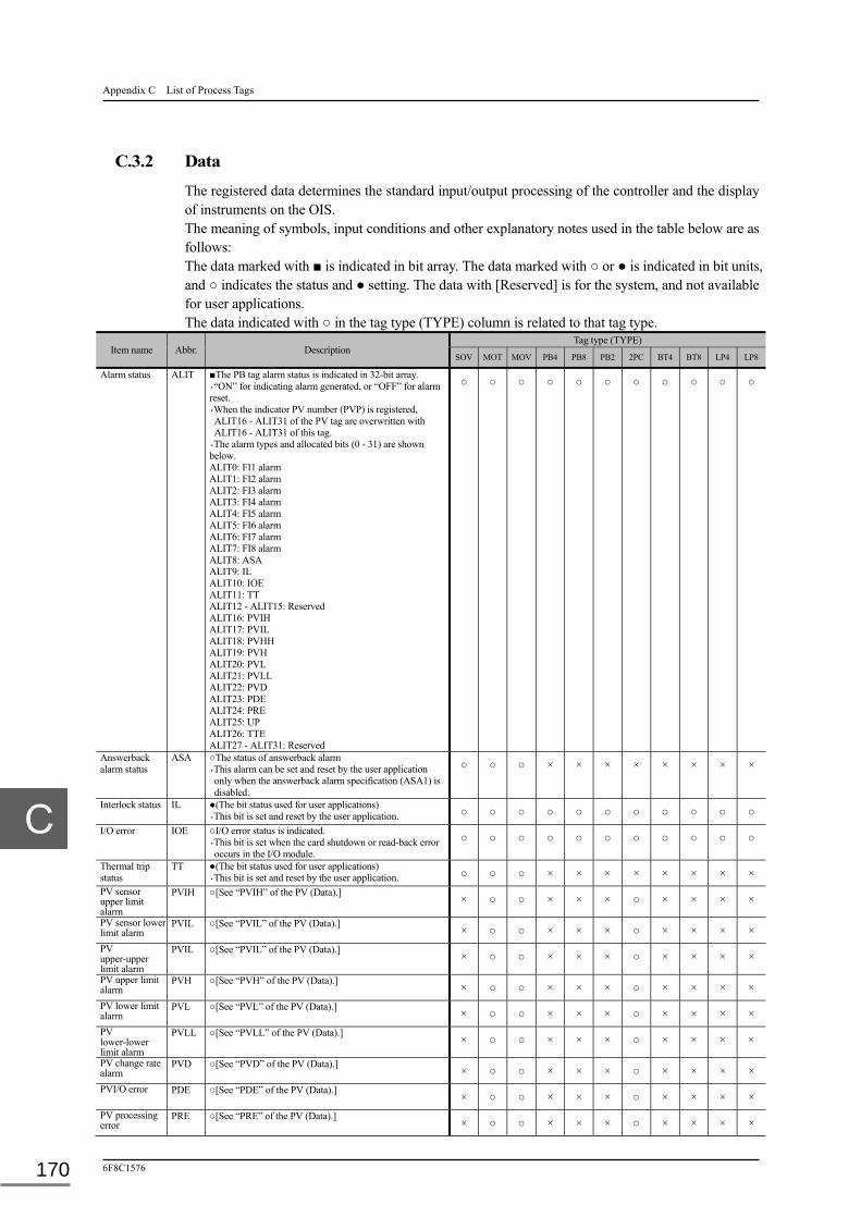
Appendix C List of Process Tags
6F8C1576 170
C.3.2 Data
The registered data determines the standard input/output processing of the controller and the display of instruments on the OIS. The meaning of symbols, input conditions and other explanatory notes used in the table below are as follows: The data marked with ■ is indicated in bit array. The data marked with ○ or ● is indicated in bit units, and ○ indicates the status and ● setting. The data with [Reserved] is for the system, and not available for user applications. The data indicated with ○ in the tag type (TYPE) column is related to that tag type.
Item name Abbr. Description Tag type (TYPE)
SOV MOT MOV PB4 PB8 PB2 2PC BT4 BT8 LP4 LP8
Alarm status ALIT ■The PB tag alarm status is indicated in 32-bit array. ・“ON” for indicating alarm generated, or “OFF” for alarm reset. ・When the indicator PV number (PVP) is registered, ALIT16 - ALIT31 of the PV tag are overwritten with ALIT16 - ALIT31 of this tag.
・The alarm types and allocated bits (0 - 31) are shown below. ALIT0: FI1 alarm ALIT1: FI2 alarm ALIT2: FI3 alarm ALIT3: FI4 alarm ALIT4: FI5 alarm ALIT5: FI6 alarm ALIT6: FI7 alarm ALIT7: FI8 alarm ALIT8: ASA ALIT9: IL ALIT10: IOE ALIT11: TT ALIT12 - ALIT15: Reserved ALIT16: PVIH ALIT17: PVIL ALIT18: PVHH ALIT19: PVH ALIT20: PVL ALIT21: PVLL ALIT22: PVD ALIT23: PDE ALIT24: PRE ALIT25: UP ALIT26: TTE ALIT27 - ALIT31: Reserved
○ ○ ○ ○ ○ ○ ○ ○ ○ ○ ○
Answerback alarm status
ASA ○The status of answerback alarm ・This alarm can be set and reset by the user application only when the answerback alarm specification (ASA1) is disabled.
○ ○ ○ × × × × × × × ×
Interlock status IL ●(The bit status used for user applications) ・This bit is set and reset by the user application. ○ ○ ○ ○ ○ ○ ○ ○ ○ ○ ○
I/O error IOE ○I/O error status is indicated. ・This bit is set when the card shutdown or read-back error occurs in the I/O module.
○ ○ ○ ○ ○ ○ ○ ○ ○ ○ ○
Thermal trip status
TT ●(The bit status used for user applications) ・This bit is set and reset by the user application. ○ ○ ○ × × × × × × × ×
PV sensor upper limit alarm
PVIH ○[See “PVIH” of the PV (Data).] × ○ ○ × × × ○ × × × ×
PV sensor lower limit alarm
PVIL ○[See “PVIL” of the PV (Data).] × ○ ○ × × × ○ × × × ×
PV upper-upper limit alarm
PVIL ○[See “PVIL” of the PV (Data).] × ○ ○ × × × ○ × × × ×
PV upper limit alarm
PVH ○[See “PVH” of the PV (Data).] × ○ ○ × × × ○ × × × ×
PV lower limit alarm
PVL ○[See “PVL” of the PV (Data).] × ○ ○ × × × ○ × × × ×
PV lower-lower limit alarm
PVLL ○[See “PVLL” of the PV (Data).] × ○ ○ × × × ○ × × × ×
PV change rate alarm
PVD ○[See “PVD” of the PV (Data).] × ○ ○ × × × ○ × × × ×
PVI/O error PDE ○[See “PDE” of the PV (Data).] × ○ ○ × × × ○ × × × ×
PV processing error
PRE ○[See “PRE” of the PV (Data).] × ○ ○ × × × ○ × × × ×

C.3 PB (Pushbutton)
Unified Controller nv series type2 light Functional Manual 171
Item name Abbr. Description Tag type (TYPE)
SOV MOT MOV PB4 PB8 PB2 2PC BT4 BT8 LP4 LP8
Alarm display status
STIT ■The PB tag alarm status is displayed in 32-bit array on the OIS Point screen after confirmation. [See “ALIT” for the alarm types and associating bits.]
○ ○ ○ ○ ○ ○ ○ ○ ○ ○ ○
Alarm confirmation status
FLIT ■The PB tag confirmation status (alarm flickering display status) is displayed in 32-bit array on the OIS Point screen). [See “ALIT” for the alarm types and associating bits.]
○ ○ ○ ○ ○ ○ ○ ○ ○ ○ ○
PB status STS ■The PB tag related status is displayed in 32-bit array. ・When the indicator PV number (PVP) is registered, STS16 - STS31 of the corresponding PV tag are overwritten on STS16 - STS31.
・Status and associating bits 0 to 31 are shown below. STS0: ASBP STS1: ILBP STS2 - STS15: Reserved STS16: SCN STS17: SIM STS18: SPR STS19: BSIM STS20: RCNF STS21: RLO STS22 - STS23: Reserved STS24: RST STS25 - STS28: Reserved STS29: SPR1 STS30: HLD STS31: Reserved
○ ○ ○ ○ ○ ○ ○ ○ ○ ○ ○
Answerback alarm bypass setting
ASBP ●(The bit status used for the user application.) ・This bit is set and reset by the user application. ○ ○ ○ × × × × × × × ×
Interlock bypass setting
ILBP ○ <Data not used in type2.> × × × × × × × × × × ×
Scan setting SCN ○[See “SCN” of the PV (Data).] × ○ ○ × × × ○ × × × ×
Simulation setting
SIM ○[See “SIM” of the PV (Data).] ・When SIM is ON, out or read-back of FO is not performed. × ○ ○ × × × ○ × × × ×
Alarm suppress setting
SPR ○[See “SPR” of the PV (Data).] (Note) The FI and ASA alarms are also subject to alarm suppression.
× ○ ○ × × × ○ × × × ×
Batch simulation setting
BSIM ○[See “BSIM” of the PV (Data).] × ○ ○ × × × ○ × × × ×
Alarm confirmation request
RCNF ○[See “RCNF” of the PV (Data).] × ○ ○ × × × ○ × × × ×
LO request RLO ○[See “RLO” of the PV (Data).] × ○ ○ × × × ○ × × × ×
Integration reset setting
RST ○[See “RST” of the PV (Data).] × ○ ○ × × × ○ × × × ×
Alarm suppress limited setting
SPR1 ○[See “SPR1” of the PV (Data).] × ○ ○ × × × ○ × × × ×
Input hold HLD ●Use this parameter to temporarily hold and resume input. ・This bit is set and reset by the user application (same as the Scan Off).
○ ○ ○ ○ ○ ○ ○ ○ ○ ○ ○
Present value [EU]
PV The present value (PV) of the PV tag is written in this bit. ・It is valid when the indicator PV number (PVP) is registered.
[See “PV” of the PV (Data).]
○ ○ ○ × × × ○ × × × ×
Lamp status FI ■This bit indicates the lamp status (1 - 8) input from the specified address in the input point variable name (IA1 - IA8).
・The input status is represented with ON and OFF.
○ ○ ○ ○ ○ ○ ○ ○ ○ ○ ○
Button status FO ■This bit indicates the button status (1 - 8) output to the address specified in the output point variable name (OA1 - OA8).
・The output status is represented with ON and OFF.
○ ○ ○ ○ ○ ○ ○ ○ ○ ○ ○
Button ON request
RFO ■This bit indicates the button ON request (1 - 8) from the OIS for operating the button.
・The button operation status is represented with ON and OFF.
○ ○ ○ ○ ○ ○ ○ ○ ○ × ×
Button lock request
IFO ■The bit status (1 - 8) used for the lock request for button operation from the OIS.
・“ON” for rejecting the button operation request. ・This bit is set and reset by the user application and the OIS.
○ ○ ○ ○ ○ ○ ○ × × × ×

Appendix C List of Process Tags
6F8C1576 172
Item name Abbr. Description Tag type (TYPE)
SOV MOT MOV PB4 PB8 PB2 2PC BT4 BT8 LP4 LP8
Control mode MOD Indicates the control mode ((M = 0, A = 1, RM = 3) ・M: The read-back value from the DO module is stored on the button status (FO). See the Remark.
・A: The button status (FO) is output to the address specified in the output point variable name (OA).
・RM: The operator manipulates the button status (FO).
○ ○ ○ ○ ○ ○ ○ × × × ×
Control mode M/A/C/RM ○BOOL type data on the control mode ・It changes with the change of the control mode (MOD).
○ ○ ○ ○ ○ ○ ○ × × × ×
Simulation input status
SINB When the simulation setting (SIM) is ON, the data in the simulation input status (SINB) is stored in the lamp status (FI) in place of the data input from the I/O module specified in the input point variable name (IA).
○ ○ ○ ○ ○ ○ ○ × × × ×
Raw count value RAW <Data not used in type2.> × × × × × × × × × × ×
Momentary operation
RFO1 ■The bit status (1 - 8) used for the momentary operation from the OIS. ○ ○ ○ ○ ○ ○ × ○ ○ × ×
FO1 momentary timer present value
MTC1 (Data for user applications) ○ ○ ○ ○ ○ ○ ○ × × × ×
FO2 momentary timer present value
MTC2 (Data for user applications) ○ ○ ○ ○ ○ ○ ○ × × × ×
FO3 momentary timer present value
MTC3 (Data for user applications) ○ ○ ○ ○ ○ ○ ○ × × × ×
User application work
USER (Data for user applications) ○ ○ ○ ○ ○ ○ ○ × × × ×
Alarm suppress setting
BSPR ■The alarm suppress status is indicated in 32-bit array. ・The bit array is the same as the alarm status (ALIT). ・“ON” for enabling the alarm suppression.
○ ○ ○ ○ ○ ○ ○ ○ ○ ○ ○
R+RM status MRM ○The control mode is M or RM. ・“ON” for M/RM mode, or “OFF” for other mode ○ ○ ○ ○ ○ ○ ○ × × × ×
M mode request REQM ○The bit status (1 - 8) indicating the M mode request. ○ ○ ○ ○ ○ ○ ○ × × × ×
A mode request REQA ○The bit status (1 - 8) indicating the A mode request. ○ ○ ○ ○ ○ ○ ○ × × × ×
DI status DIP ■The bit status (1 - 8) indicating the status of DI (before signal inversion).
○ ○ ○ ○ ○ ○ ○ × × × ×
DI status change DICH ■The bit status (1 - 8) indicating the DI status change. ○ ○ ○ ○ ○ ○ ○ × × × ×
DO status DOP ■The bit status (1 - 8) indicating the status of DO (after signal inversion). ○ ○ ○ ○ ○ ○ ○ × × × ×
Raw count value (double length)
DRAW The same value with the raw count (RAW) of the PV tag is indicated. ・This bit is valid when the indicator PV number (PVP) is registered.
[See “RAW” of the PV (Data).]
○ ○ ○ ○ ○ ○ ○ × × × ×
Remark
・In M mode, the read-back of the output data of the button status (FO) When the control mode can be selected with the module parameter
(the default setting is read-back).
[For settings, see Chapter 7 nV-Tool Support Function, 7.1.5 Others and Ethernet.]

C.4 TC (Timer/Counter)
Unified Controller nv series type2 light Functional Manual 173
C.4 TC (Timer/Counter)
The TC tag registers general data on the timer/counter, standard processing and instrument display.
C.4.1 Parameters
The input conditions are itemized and each condition begins with ●. Input is allowed only when all conditions are met. The parameter marked with ■ in the description column is indicated in bit array. The parameter marked with ○ in the tag type (TYPE) column is related to that tag type.
Item name Abbr. Description Tag type (TYPE)
TIM CNT
Tag number TAG Specifies the identification number given to the instrument. ●Set a number in up to 16 characters including numbers, letters and underbars. Begin the character-string with a letter. ●Use a unique number in the system. ●Do not use the reserved word in the system. Lower and upper case letters are not discriminated. All are treated as upper case letters.
○ ○
Tag name NAME Specifies the name of this instrument. ●Up to 32 characters. ○ ○
Tag type TYPE ●Select the function type of the instrument from those listed below. ・Not used ・TIM (Timer) ・CNT (Counter)
○ ○
Display pattern model number
MDL Specifies the instrument display pattern on the OIS. ●0 - 9. ・Enter 0 for the standard pattern. ・Enter 1 to 9 for the indication pattern created by the user.
○ ○
Signal type number AREA Specifies the instrument signals for grouping in the whole system. ●0 - 63. ○ ○
Automatic screen display number
SCNO Sets the OIS screen automatically selected when an alarm is generated. ●0 - 1024. ・Enter 0 for disabling the automatic display.
○ ○
Operation inhibition LOCK Specifies whether to permit or inhibit operator action when an instrument tag is set on the OIS. ●Permit, Inhibit. ○ ○
Tag color COLR Specifies the tag display color. ●White, Red, Green, Yellow, Blue, Purple, Azure, Black, Light perse, Subdued orange, Perse,
Orange, Brilliant gray, Bright gray, Gray, Deep gray, Dark gray, Perse, Grayish blue, Light gray, Charcoal, Reddish brown , Green tea, Hay, Indigo, Navy-blue, Sage green, Subdued gray, Light green, Subdued white, Subdued greenish yellow, Subdued charcoal.
○ ○
Tag letter SIGN Specifies the character string representing a tag. ●Up to 16 characters ○ ○
Alarm confirmation method
ATYP Specifies the method of generating and confirming the alarm. ●Method A or Method B ・Methods other than the above are invalid.
○ ○
Alarm monitor common setting
AMON Specifies whether to monitor the alarm of an instrument. ●ON, OFF ○ ○
Control scan setting PRS Specifies the execution cycle of the standard input/output of the PV tag. ●Main, High-speed ・Select either the main or high-speed scan
○ ○
Sub-schedule number SCH <Data not used in type2.> × ×
Grouping number GRP <Data not used in type2.> × ×
Station fixed register processing setting
SFRP <Data not used in type2.> × ×
Alarm monitoring individual setting
MON ■Specify whether to monitor the alarm (ON or OFF) for individual alarms (0 to 31). ●ON, OFF ・The setting is valid when the alarm monitoring common setting (AMON) is ON. [For details of alarms, see “ALIT” of the PV (Data).]
○ ○
Alarm grade type AGRD ■Specify the alarm grade for individual alarms (0 to 31). ●None, Attention, Minor Alarm, Intermediate Alarm, Major Alarm. [For details of alarms, see “ALIT” of the PV (Data).]
○ ○
Engineering unit EU Sets the engineering unit character for the PV. ●Up to 16 characters. ○ ○

Appendix C List of Process Tags
6F8C1576 174
Item name Abbr. Description Tag type (TYPE)
TIM CNT
Time unit TMEU Selects the unit of present timer value. ●Second (1), Minute (60), Hour (3600), Day (86400) ・When setting this parameter, note that the real number arithmetic accuracy in the standard input/output processing is five to six digits in decimal.
○ ×
Decimal point position DCML Specifies the decimal point of the value on the OIS instrument screen for display PV or range. ●0 - 5. ○ ○
Range upper limit MAX The upper limit of the timer or counter data ・Counting resumes from zero when the present value (PV) exceeds this value (called the rollover processing).
[See Chapter 6 Standard Input/Output, 6.4 Details of Data Input and Output Functions, ● TC processing.
○ ○
Range lower limit MIN The lower limit of the counter data. ・Counting resumes from zero when the present value (PV) falls below this value (called the rollover processing).
[See Chapter 6 Standard Input/Output, 6.4 Details of Data Input and Output Functions, ● TC processing.
× ○

C.4 TC (Timer/Counter)
Unified Controller nv series type2 light Functional Manual 175
C.4.2 Data
The registered data determines the standard input/output processing of the controller and the display of instruments on the OIS. The meaning of symbols, input conditions and other explanatory notes used in the table below are as follows: The data marked with ■ is indicated in bit array. The data marked with ○ or ● is indicated in bit units, and ○ indicates the status and ● setting. The data with [Reserved] is for the system, and not available for user applications. The data indicated with ○ in the tag type (TYPE) column is related to that tag type.
Item name Abbr. Description Tag type (TYPE)
TIM CNT
Alarm status ALIT ■The PC tag alarm status is indicated in 32-bit array. ・The alarm types and allocated bits (0 - 31) are shown below. ・“ON” (1) for alarm generated, and “OFF” (0) for alarm reset. ALIT0 - ALIT7: Reserved ALIT8: PRE ALIT9: UP ALIT10: DOWN ALIT11 : ON ALIT12 - ALIT31: Reserved
○ ○
PV processing error PRE ○ <Data not used in type2.> × ×
Upper limit setting value reached status
UP ○An alarm generated when 0 < Setting value (SV) < Present value (PV). ○ ○
Lower limit setting value reached status
DOWN ○An alarm generated when Present value (PV) < Setting value (SV) < 0. See the Remark. × ○
Counting status ON ○An alarm generated when the timer is updated (0 < Present value (PV))). See the Remark. ○ ×
Alarm display status STIT ■The alarm status is displayed in 32-bit array on the OIS Point screen after confirmation. [See “ALIT” for the alarm types and associating bits.] ○ ○
Alarm confirmation status
FLIT ■The alarm confirmation status (alarm flickering display status) is displayed in 32-bit array on the OIS Point screen). [See “ALIT” for the alarm types and associating bits.]
○ ○
TC processing STS The timer/counter related status is displayed in 32-bit array. (Status and associating bits 0 to 31 are shown below.) STS0 - STS15: Reserved STS16: SCN STS17: Reserved STS18: SPR STS19: Reserved STS20: RCNF STS21: RLO STS24: RST STS25: STAT STS26: STOP STS27: INCR STS28: DECR STS22, 23, STS29 - STS31: Reserved
○ ○
Scan setting SCN ○“OFF” for updating the present value (PV) of the counter. × ○
Alarm suppress setting SPR ○ <Data not used in type2.> × ×
Alarm confirmation request
RCNF ○The bit status used for the CNF request from the OIS. (This area is not available for user applications.) ○ ○
LO request RLO ○The bit status used for the LO request from the OIS. (This area is not available for user applications.) ○ ○
Remark
[For details of when alarms are output, see Chapter 6, Standard I/O 6.4 Details of Standard I/O Processing, ● TC processing.]

Appendix C List of Process Tags
6F8C1576 176
Item name Abbr. Description Tag type (TYPE)
TIM CNT
Reset request RST ○“ON” resets the present value (PV) to zero. ・The reset request can be entered from the user application (RST = ON).
Clearing the reset request (RST=OFF) is made during the standard output processing.
○ ○
Start request STAT ○“ON” starts the timer update. ・The reset request can be entered from the user application (STAT = ON). Clearing the start request (STAT = OFF) is made during the standard output processing.
○ ×
Stop request STOP ○“ON” stops the timer update. ・The stop request can be entered from the user application (STOP = ON). Clearing the stop request (STOP = OFF) is made during the standard output processing.
○ ×
Increment request INCR ○“ON” increments the present value on the counter. ・The increment request can be entered from the user application (INCR = ON). Clearing the increment request (INCR = OFF) is made during the standard output processing.
× ○
Decrement request DECR ○“ON” decrements the present value on the counter. ・The decrement request can be entered from the user application (RST = ON). Clearing the decrement request (DECR = OFF) is made during the standard output processing.
× ○
Present value PV The present value of the timer/counter. ○ ○
Setting value SV The setting (preset) value of the timer/counter. ○ ○

C.5 DB (Data Block)
Unified Controller nv series type2 light Functional Manual 177
C.5 DB (Data Block)
The DB tag registers general data on the data block instrument display.
C.5.1 Parameters
The input conditions are itemized and each condition begins with ●. Input is allowed only when all conditions are met. The parameter marked with ■ in the description column is indicated in bit array. The parameter marked with ○ in the tag type (TYPE) column is related to that tag type.
Item name Abbr. Description Tag type (TYPE)
DB1 DB8
Tag number TAG Specifies the identification number given to the instrument. ●Set a number in up to 16 characters including numbers, letters and underbars. Begin the character-string with a letter. ●Use a unique number in the system. ●Do not use the reserved word in the system. Lower and upper case letters are not discriminated. All are treated as upper case letters.
○ ○
Tag name NAME Specifies the name of this instrument. ●Up to 32 characters. ○ ○
Tag type TYPE ●Select the function type of the instrument from those listed below. ・Not used ・DB1, (1 point) ・DB8, (8 points)
○ ○
Display pattern model number
MDL Specifies the instrument display pattern on OIS. ●0 - 9. ・Enter 0 for the standard pattern. ・Enter 1 to 9 for the indication pattern created by the user.
○ ○
Signal type number AREA Specifies the instrument signals for grouping in the whole system. ●0 - 63. ○ ○
Automatic screen display number
SCNO Sets the OIS screen automatically selected when an alarm is generated. ●0 - 1024. ・Enter 0 for disabling the automatic selection.
○ ○
Operation inhibition LOCK Specifies whether to permit or inhibit operator action when an instrument tag is set on the OIS. ●Permit, Inhibit. ○ ○
Tag color COLR Specifies the tag display color. ●White, Red, Green, Yellow, Blue, Purple, Azure, Black, Light perse, Subdued orange, Perse,
Orange, Brilliant gray, Bright gray, Gray, Deep gray, Dark gray, Perse, Grayish blue, Light gray, Charcoal, Reddish brown , Green tea, Hay, Indigo, Navy-blue, Sage green, Subdued gray, Light green, Subdued white, Subdued greenish yellow, Subdued charcoal.
○ ○
Tag letter SIGN Specifies the character string representing a tag. ●Up to 16 characters ○ ○
Setting value (real number)
R ■Set the initial value of the setting value (real number) for eight points (one point for DB1). ○ ○
Setting value (long integer)
D ■Set the initial value of the setting value (long integer) for eight points (one point for DB1). ○ ○
Setting value (integer) W ■Set the initial value of the setting value (integer) for eight points (one point for DB1). ・The setting value is significant only for the item specified with the setting value data type (DTYP). ○ ○
Setting value upper limit (real number)
RH ■Set the upper limit of the setting value (real number) for eight points (one point for DB1). ○ ○
Setting value upper limit (long integer)
DH ■Set the upper limit of the setting value (long integer) for eight points (one point for DB1). ○ ○
Setting value upper limit (integer)
WH ■Set the upper limit of the setting value (integer) for eight points (one point for DB1). ・The upper limit is significant only for the item specified with the setting value data type (DTYP). ・The input limited value and graph range can be entered from the OIS only for the items specified with DTYP.
○ ○
Setting value lower limit (real number)
RL ■Set the lower limit of the setting value (real number) for eight points (one point for DB1). ○ ○
Setting value lower limit (long integer)
DL ■Set the lower limit of the setting value (long integer) for eight points (one point for DB1). ○ ○
Setting value lower limit (integer)
WL ■Set the lower limit of the setting value (integer) for eight points (one point for DB1). ・The lower limit is significant only for the item specified with the setting value data type (DTYP). ・The input limited value and graph range can be entered from the OIS only for the items specified with DTYP.
○ ○
Setting value data type DTYP ■Select the data type of setting value for each of eight points. ●Note used, Real Number, Long Integer, Integer ○ ○
Decimal point position DCML ■Specify the decimal digits to display the instrument value on the OIS. ●0 - 5 ○ ○
Engineering unit letter EU ■Set the engineering unit letter for the setting value. ●Up to 16 characters ○ ○
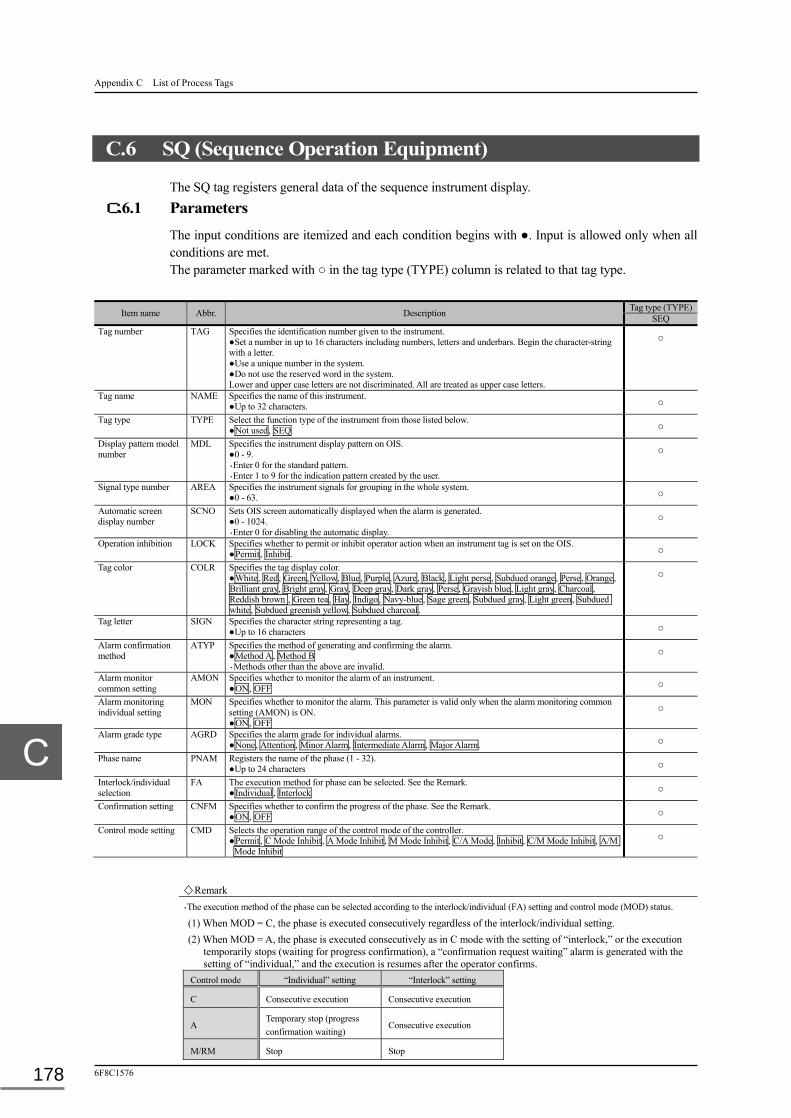
Appendix C List of Process Tags
6F8C1576 178
C.6 SQ (Sequence Operation Equipment)
The SQ tag registers general data of the sequence instrument display.
C.6.1 Parameters
The input conditions are itemized and each condition begins with ●. Input is allowed only when all conditions are met. The parameter marked with ○ in the tag type (TYPE) column is related to that tag type.
Item name Abbr. Description Tag type (TYPE)
SEQ Tag number TAG Specifies the identification number given to the instrument.
●Set a number in up to 16 characters including numbers, letters and underbars. Begin the character-string with a letter. ●Use a unique number in the system. ●Do not use the reserved word in the system. Lower and upper case letters are not discriminated. All are treated as upper case letters.
○
Tag name NAME Specifies the name of this instrument. ●Up to 32 characters. ○
Tag type TYPE Select the function type of the instrument from those listed below. ●Not used, SEQ ○
Display pattern model number
MDL Specifies the instrument display pattern on OIS. ●0 - 9. ・Enter 0 for the standard pattern. ・Enter 1 to 9 for the indication pattern created by the user.
○
Signal type number AREA Specifies the instrument signals for grouping in the whole system. ●0 - 63. ○
Automatic screen display number
SCNO Sets OIS screen automatically displayed when the alarm is generated. ●0 - 1024. ・Enter 0 for disabling the automatic display.
○
Operation inhibition LOCK Specifies whether to permit or inhibit operator action when an instrument tag is set on the OIS. ●Permit, Inhibit. ○
Tag color COLR Specifies the tag display color. ●White, Red, Green, Yellow, Blue, Purple, Azure, Black, Light perse, Subdued orange, Perse, Orange, Brilliant gray, Bright gray, Gray, Deep gray, Dark gray, Perse, Grayish blue, Light gray, Charcoal, Reddish brown , Green tea, Hay, Indigo, Navy-blue, Sage green, Subdued gray, Light green, Subdued white, Subdued greenish yellow, Subdued charcoal.
○
Tag letter SIGN Specifies the character string representing a tag. ●Up to 16 characters ○
Alarm confirmation method
ATYP Specifies the method of generating and confirming the alarm. ●Method A, Method B ・Methods other than the above are invalid.
○
Alarm monitor common setting
AMON Specifies whether to monitor the alarm of an instrument. ●ON, OFF ○
Alarm monitoring individual setting
MON Specifies whether to monitor the alarm. This parameter is valid only when the alarm monitoring common setting (AMON) is ON. ●ON, OFF
○
Alarm grade type AGRD Specifies the alarm grade for individual alarms. ●None, Attention, Minor Alarm, Intermediate Alarm, Major Alarm. ○
Phase name PNAM Registers the name of the phase (1 - 32). ●Up to 24 characters ○
Interlock/individual selection
FA The execution method for phase can be selected. See the Remark. ●Individual, Interlock ○
Confirmation setting CNFM Specifies whether to confirm the progress of the phase. See the Remark. ●ON, OFF ○
Control mode setting CMD Selects the operation range of the control mode of the controller. ●Permit, C Mode Inhibit, A Mode Inhibit, M Mode Inhibit, C/A Mode, Inhibit, C/M Mode Inhibit, A/M
Mode Inhibit
○
Remark
・The execution method of the phase can be selected according to the interlock/individual (FA) setting and control mode (MOD) status.
(1) When MOD = C, the phase is executed consecutively regardless of the interlock/individual setting.
(2) When MOD = A, the phase is executed consecutively as in C mode with the setting of “interlock,” or the execution temporarily stops (waiting for progress confirmation), a “confirmation request waiting” alarm is generated with the setting of “individual,” and the execution is resumes after the operator confirms.
Control mode “Individual” setting “Interlock” setting
C Consecutive execution Consecutive execution
A Temporary stop (progress confirmation waiting)
Consecutive execution
M/RM Stop Stop

C.6 SQ (Sequence Operation Equipment)
Unified Controller nv series type2 light Functional Manual 179
C.6.2 Data
The registered data determines the standard input/output processing of the controller and the display of instruments on the OIS. The data marked with ■ is indicated in bit array. The data marked with ○ or ● is indicated in bit units, and ○ indicates the status and ● setting. The data with [Reserved] is for the system, and not available for user applications. The input conditions are itemized and each condition begins with ●. Input is allowed only when all conditions are met. The data indicated with ○ in the tag type (TYPE) column is related to that tag type.
Item name Abbr. Description
Tag type (TYPE) SEQ
Alarm status ALIT ■The SEQ tag alarm status is indicated in 32-bit array. ・ON (1) indicates alarm generated, and OFF (0) alarm reset. ・The alarm types and allocated bits (0 - 31) are shown below. ALIT0 - ALIT11: Reserved ALIT12: STA ALIT13: ASA ALIT14: ILA: ALIT15: CNRQ ALIT16 - ALIT31: Reserved
○
Stall alarm status STA ○The stall alarm for phase execution. ・This alarm is generated when the phase does not go on within the stall monitoring time setting value.
○
Answerback alarm status ASA ○Answerback alarm of the answer step instruction. ・This alarm is generated when the answer step does not go on within the answerback monitoring timer setting value.
○
Interlock alarm status ILA <Not used in the SQ tag.>
○
Confirmation request waiting
CNRQ ○An alarm for waiting the phase execution confirmation. ・This alarm is generated when confirmation is queued, and reset when confirmation is made.
○
Alarm display status STIT ■The alarm status is displayed in 32-bit array on the OIS Point screen after confirmation. [See “ALIT” for the alarm types and associating bits.]
○
Alarm confirmation status
FLIT ■The LP tag confirmation status (alarm flickering display status) is displayed in 32-bit array on the OIS Point screen). [See “ALIT” for the alarm types and associating bits.]
○
SEQ status STS ■The sequencer related status is displayed in 32-bit array. Status and associating bits 0 to 31 are shown below. STS0 - STS12:Reserved STS13: SSS STS14: SPR STS15: SSE STS16 - STS19: Reserved STS20: RCNF STS21: RLO STS22 - STS30: Reserved STS31: CNE
○
Single step mode ゙ SSS ○ <Data not used in type2.>
Alarm suppress setting SPR Sets whether to disable (ON) or enable (OFF) of alarm suppression. ●ON, OFF ・The confirmation waiting alarms are excluded.
○
Single step execution SSE ○The bit status used when a single scan of sequence is forcibly executed from nV-tool when the control mode is “M/RM.”
○
Alarm confirmation request
RCNF ○The bit status used when the alarm confirmation request is processed on the OIS. ○
LO request RLO ○The bit status used when the LO request is processed on the OIL. ○
Confirmation request CNE ○The bit status used when the confirmation request is processed on the OIS. ○
Active phase map PHNO ■The currently executed phase (1 - 32) is indicated in bit map.
○
Alarm phase map ALNO ■The stalled phase (1 - 32) is indicated in bit map.
○
Confirmation waiting phase map
CNNO ■The confirmation waiting phase (1 - 32) is indicated in bit map. ○
Active phase number setting
APNO The phase number of the phase currently executed (1 - 32) is indicated in bit map. ○
Existing phase map EXNO ■The registered phase (1 - 32) is indicated in bit map. ○
Changeover permit phase map
JGNO ■The changeover permitted phase (1 - 32) is indicated in bit map. ○
Control mode MOD The control mode is indicate (M = 0, A = 1, C = 2, RM = 3)
○
Control mode M/A/C /RM
The control mode is indicated with BOOL type data. ○

180
Appendix D Run-Time Calculation
D.1 Scan Cycle Calculation ····················································· 181
D.2 Operable Application at the Maximum Speed ························· 182

D.1 Scan Cycle Calculation
Unified Controller nv series type2 light Functional Manual 181
D.1 Scan Cycle Calculation
How to calculate the run-time of the HS/MS scan, and find the suitable scan cycle are described in this section.
Calculation of MS/HS scan run-time Scan run-time = User program + Batch input/output time + Tracking transmission time
+ Standard Input/output processing time + Tag transmission time + OIS message processing time
Item Run-time [ms]
MS scan HS scan User program See Execution speed of Appendix A.1. Batch I/O 0.07 TC-net I/O Batch I/O amount (W) +
0.003 Intelligent serial I/O Batch I/O amount (W) Standard I/O 0.05 No. of PV points + 0.08 No. of LP ponts +
0.18 No. of LB points (*1) Tracking transmission (*2) 40 + 1.0 Tracking amount (KW) 5.0 + 1.0 Tracking amount (KW) Tag transfer 76 + 0.14 No. of PV points +
0.19 No. of LP points + 0.22 No. of PB points
0.1 + 01.4 No. PV points + 0.19 No. LP points + 0.22 No. of PB points
OIS message processing 0.3 No. of messages (*3) 0 (The unit is “ms” except when specifically indicated)
*1 See Appendix A.1 Function Specification for details of standard I/O time condition. *2 The amount of tracking can be checked in the ZW56 and ZW58 tracking amount indication.
ZW56 (HS tracking mount) and ZW58 (MS tracking amount) also contain the fixed sizes shown below, respectively. Use the ZW56 and ZW58 values including these fixed size.
HS=7538W、MS=36446W *3 Normally about 0ms. It should be processed in accordance with the change of items at alarm
change, FI/FO change, or the change in tag parameter.
Calculation of MS scan cycle by taking HS interruption into account When the HS scan breaks in the MS scan, the MS scan time is prolonged by the HS scan time. The following expression is used to calculate the MS scan cycle by taking the interruption of the HS scan into account: {(MS scan cycle/HS scan cycle) * HS scan run-time + MS scan run-time} < MS scan cycle
Note
・Set the scan cycle time when the free time is in about 20% of the scan times to secure stable operation by checking the time required for all tasks, and individual scan times. (For details, see 7.2.1 Task run time measurement in Chapter 7.)

Appendix D Run-Time Calculation
6F8C1576 182
D.2 Operable Application at the Maximum Speed
An example of operable application at the maximum speed (HS scan cycle = 10ms, MS scan cycle = 100ms) in the duplex system is shown below.
[Condition]
Configure: PUM21 2 Only one intelligent serial I/O (AI01, AO01, DI01, DO01)
Item HS MS
Condition of measurement
Program step (Step) 128 512
PID tag (Point) 0 8
PB8 tag (Point) 0 30

183
Appendix E Migration method from L2PU22 system This chapter explains the method to migrate to the Unified Controller nv series type2 light by the
system of Integrated Controller V series model2000:L2PU22 (herein after called the “L2PU22”).
E.1 Judgment for Migration ···················································· 184
E.2 Ready for Migration ························································· 185
E.2.1 Copy of the system ················································· 185
E.2.2 Deletion of the unnecessary element of the L2PU22 station · 185
E.2.3 Export of L2PU22 station ········································· 185
E.2.4 Export of the tag ···················································· 187
E.2.5 Export of the variable value ······································· 187
E.3 Operation for Migration ···················································· 189
E.3.1 Entry of the hardware constitution ······························· 189
E.3.2 Entry of the standard variable ···································· 189
E.3.3 Import of the tag ···················································· 189
E.3.4 Import of the variable value ······································· 189
E.3.5 Batch compile ······················································ 189
E.4 Detailed Contents of Operation ··········································· 190
E.4.1 Editing of the station export file ·································· 190
E.4.2 Editing of the tag export file ······································ 193
E.4.3 Entry of the module parameter ··································· 194

Appendix E Migration method from L2PU22 system
6F8C1576 184
E
E.1 Judgment for Migration
For L2PU22 system, confirm that all the following conditions are established. If a condition is
concluded with none of one; to type2 light cannot migrate.
Gather up the unit on the serial bus, and is satisfied within a mark with a use tag; need it, and
examine a system of L2PU22 so that a condition is concluded.
When it is not gained in specifications of type2 light, it becomes the shift to type2(PU821). With
[2] of E.2.3 Export of L2PU22 station, entry hardware constitution as PU821.
G2I/O cannot migrate simply in the future for a support plan. When it is migrated, the system
which G2I/O module is connected to performs an inquiry and.
[Migration condition]
・Main slot entry being use only for L2PU22 and FN611.
(When there is S2PU**, it is migrated to PU821.)
・User system alarm being use only for A00 and A01.
(When A02(S2PU**) is used, it is impossible of a migration.)
・Meet the migration condition of the list shown below.
Table E.1-1 Migration condition
Item type2 light L2PU22 Migration condition (Note1) Task Event (EV) 8tasks(1task/1program) 16tasks(1task/1program) 8tasks or less Interruption (IP) 8tasks(1task/1program) 32tasks(1task/1program) 8tasks or less High-speed scan (HS) 1task(1task/8programs) 1task(1task/128programs) 8programs or less Main scan (MS) 1task(1task/64programs) 1task(1task/256programs) 64programs or less Background (BG) (nothing) 4tasks(1task/1program) Nothing Program size 128Kstep 512Kstep 128Kstep or less No. of POU 1000 2048 1000 or less Process tag Indicator (#PV) 384points 768points 384points or less Controller (#LP) 128points 256points 128points or less Digital instrument (#PB) 512points 1024points 512points or less Timer/counter (#TC) 64points 128points 64points or less Sequence (#SQ) 64points 128points 64points or less Database (#DB) 128points 256points 128points or less Polygonal line table (#P) 128points 256points 128points or less Timer (#T) 256points 512points 256points or less Counter (#C) 128points 128points (judgment unnecessary) Real parameter (#R) 2048points 4096points 2048points or less Integer parameter (#W) 640points 1280points 640points or less Real time trend (#RTT) 512points 512points (judgment unnecessary) Data size Local variables 60KW 128KW 60KW or less Global variables 4KW 16KW 4KW or less IQ register 16KW 18KW 16KW or less ZW register 7KW 8KW (Note2) (judgment unnecessary) DW register 32KW 64KW 32KW or less AW register 64KW 64KW (judgment unnecessary) MW register 1KW 1KW (judgment unnecessary) Serial I/O 15units×14slots×2buses 15units×14slots×3buses 15units×14slots×2buses or less
Remark
(Note1) In the item where is equal to specifications of L2PU22 specifications of type2 light or the item covering all, the judgment of the migration is unnecessary.
(Note2) It becomes the system reservation area in the latter half (4KW) of ZW register of L2PU22.
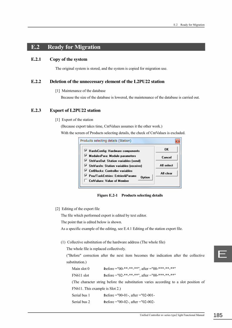
E.2 Ready for Migration
Unified Controller nv series type2 light Functional Manual 185
E
E.2 Ready for Migration
E.2.1 Copy of the system
The original system is stored, and the system is copied for migration use.
E.2.2 Deletion of the unnecessary element of the L2PU22 station
[1] Maintenance of the database
Because the size of the database is lowered, the maintenance of the database is carried out.
E.2.3 Export of L2PU22 station
[1] Export of the station
(Because export takes time, CntValues assumes it the other work.)
With the screen of Products selecting details, the check of CntValues is excluded.
Figure E.2-1 Products selecting details
[2] Editing of the export file
The file which performed export is edited by text editor.
The point that is edited below is shown.
As a specific example of the editing, see E.4.1 Editing of the station export file.
(1) Collective substitution of the hardware address (The whole file)
The whole file is replaced collectively.
("Before" correction after the next item becomes the indication after the collective
substitution.)
Main slot 0 :before ="00-**-**-**", after ="00-***-**-**"
FN611 slot :before ="02-**-**-**", after ="00-***-**-**"
(The character string before the substitution varies according to a slot position of
FN611. This example is Slot 2.)
Serial bus 1 :before ="00-01-, after ="02-001-
Serial bus 2 :before ="00-02-, after ="02-002-

Appendix E Migration method from L2PU22 system
6F8C1576 186
E
(2) Correction of the station name (@Stn)
Name (Station name) :It is revised to an appropriate name.
(It becomes the name that is different from the station
performed export of.)
Catcode (Station classification) :"nv light station" (It is this value by all means.)
(3) Hardware configuration information (@HardsConfig)
The information of the main slot is changed to the fixed information of PUM21.
Base :"**-***-**-**","BUM22",""
Slot 0 :"00-***-**-**","PUM21",""
Slot 2 :"02-***-**-**","SBM21",""
(4) Deletion of the unnecessary information
The following information is deleted.
@IOCnnArea_Task, @Resource, @IOLoopConInfo, @StnVarsOut, @StnVarsIn
(5) Module parameter (@ModulesPara) / Point parameter (@PointsPara)
The module parameter of the main slot and a point parameter are deleted. (After two
items are lines of “*” like Haddress="nn-***-**-**")
The intelligent serial is the same. (Haddress="02-001-・・・" or "02-001-・・・")
(6) Controller memory (@CntVars)
Because it is registered in E.3.2 Entry of the standard variable, as for the standard
variable, the import file is deleted.
Because it is imported by tag editor, there are not tag variable (PV and R) in an import
file.
The variable of the user definition is changed as follows by the kind of the variable.
ZW :It is a correction-free.
User :It is a correction-free.
AW :If there is a word number of the AW in the range of 0-65,535, Name is
changed to the AW. It is a correction-free other than it.
BW :If there is a word number of the BW in the range of 65,536-66,559, Name
is changed to the ZW, and WordNo becomes -63,836.
The array range is revised so that WordNo becomes the range to 1717 in
the case of the array type.
MW :If there is a word number of the MW in the range of 66,560-67,583,
Name is changed to the MW, and WordNo becomes +11,680. It is a
correction-free other than it.
DW :WordNo becomes -45,184. It is a correction-free other than it.

E.2 Ready for Migration
Unified Controller nv series type2 light Functional Manual 187
E
SysAlarm :A02 is deleted. Name is changed to ZW, and Datatype and WordNo are
changed about A00,A01,U01. (As a specific example of the editing, see
E.4.1 Editing of the station export file.)
I/O variable :It is a correction-free. (WordNo is different closely. However, nV tool
distinguishes Haddress and revises WordNo automatically.)
(7) POU entry (@PouEntries)
It is a correction-free.
(8) Task entry (@TaskEntries)
The entry which there is not in PUM21 is deleted.
Target for deletion :EV8-EV15, IP8-IP31, HS8-HS127, MS64-MS255, BG0-BG3
E.2.4 Export of the tag
[1] Export of the tag
It is made export to the tag points of PUM21. (About the points every variable, see E.1
Judgment of Migration.)
FN611 performs export of only RTT. Because a variable except RTT of FN611 is a variable
for S2, it is excluded.
[2] Editing of the tag export file
Because the hardware address of intelligent serial I/O is changed, the input and output
variable name (PVA, MVA, Ian, OAn) are revised.
Input count upper / lower limit (CH, CL) are changed to DCH, DCL.
For details, see E.4.2 Editing of the tag export file.
E.2.5 Export of the variable value
[1] Export of the station (Only in CntValues)
With the screen of Products selecting details, only CntValues is checked.
Figure E.2-2 Products selecting details (Only in CntValues)

Appendix E Migration method from L2PU22 system
6F8C1576 188
E
[2] Editing of the export file
(1) Correction of the station name (@Stn)
Name (Station name) :It is revised to an appropriate name.
(It becomes the name that is different from the station
performed export of.)
Catcode (Station classification) :"nv light station" (It is this value by all means.)
(2) Deletion of the header information
The header of the tag variable (PV_HEAD etc.) is deleted for an unnecessary.
(3) Controller memory (@CntVars)
The number of element of R, W, DW are changed to the number of PUM21. (The
unnecessary variable is deleted.)
(4) Collective substitution of the hardware address (The whole file)
The whole file is replaced collectively.
Main slot 0 :before ="00-**-**-**", after ="00-***-**-**"

E.3 Operation for Migration
Unified Controller nv series type2 light Functional Manual 189
E
E.3 Operation for Migration
E.3.1 Entry of the hardware constitution
[1] Import of the station export file
The file performed export of in E.2.3 Export of L2PU22 station is imported.
When an error occurs by import, the import file is revised according to error message, and try
it again.
PUM21 is added to [Networks]-[EtherLANDouble]-[Modules].
Figure E.3-1 Import of the station export file
[2] Module parameter entry of PUM21
Setting of L2PU22 is registered with PUM21 in reference to E.4.3 Entry of the module
parameter.
E.3.2 Entry of the standard variable
Register all the standard variables registered in L2PU22 including PV_PARA.
E.3.3 Import of the tag
All the files which performed export in E.2.4 Export of the tag are imported.
Note • When Tag number (TAG) is just misappropriated, delete the tag of L2PU22 or the station.
It is not imported by Tag number overlap check function in the system.
E.3.4 Import of the variable value
The file performed export of in E.2.5 Export of the variable value is imported.
E.3.5 Batch compile
In the imported state, the program code is not generated.
The batch compile is carried out, and confirm that a program and each variable are registered
definitely.

Appendix E Migration method from L2PU22 system
6F8C1576 190
E
E.4 Detailed Contents of Operation
E.4.1 Editing of the station export file
The specific example in the editing of the export file with [2] of E.2.3 Export of L2PU22 station
is shown.
Table E.4-1 Editing of the station export file (E.2.3 [2])
Index of the export file Before After @Stn (Example: Station name (Name) is different by the system.) (* Name,Catcode *) "L2PU22","model 2000" "PUM21","nv light station" @HardsConfig (* HAddress,Catcode,Comment *) The by all means following fixation. "**-**-**-**","BU643DDouble","" "**-***-**-**","BUM22","" "00-**-**-**","L2PU22_X","" "00-***-**-**","PUM21","" "02-**-**-**","FN611","" "02-***-**-**","SBM21","" "03-**-**-**","IF619","" @End_HardsConfig @IOCnnArea_Task Delete : Delete @End_IOCnnArea_Task Delete @Resource Delete : Delete @End_Resource Delete @IOLoopConInfo Delete : Delete @End_IOLoopConInfo Delete @StnVarsOut Delete Delete @End_StnVarsOut Delete @StnVarsIn Delete : Delete @End_StnVarsIn Delete @ModulesPara (* HAddress,OrderNo,cItemID,Value *) 00-***-**-**,"1","3225","1" Delete 00-***-**-**,"2","3233","1" Delete 00-***-**-**,"3","3311","0" Delete : 02-**-**-**,"1","3353","1" Delete 02-**-**-**,"2","3354","1" Delete 02-**-**-**,"3","3227","0" Delete 02-001-01-01,"1","6019","1" Because it is intelligent I/O, it is a correction unnecessary. (just) : @End_ModulesPara @PointsPara (* HAddress,OrderNo,cItemID,Value,PointNo *) 00-***-**-**,"1","3513","0","1" Delete 00-***-**-**,"2","3512","0","1" Delete 00-***-**-**,"3","3511","0","1" Delete : 02-001-01-01,"1","6107","1","1" Because it is intelligent I/O, it is a correction unnecessary. (just) : @End_PointsPara @CntBlocks (* HAddress,Name *) 00-***-**-**,"User" Correction unnecessary 00-***-**-**,"DW" Correction unnecessary @CntVars (* HAddress,Name,IOW,Variable,Datatype,Value,Comment,Speed,Const,WordNo,BitNo,IOA,RIO *) 00-***-**-**,"ZW","","ZW","ARRAY[0..8191] OF WORD"・・・ Delete (ZW which is registered in E.3.2) 00-***-**-**,"ZW","","ZF","ARRAY[0..4095] OF REAL"・・・ Delete (ZW which is registered in E.3.2) 00-***-**-**,"ZW","","Z","ARRAY[0..8191] OF TYPE16BITS"・・・ Delete (ZW which is registered in E.3.2) 00-***-**-**,"User","","USR_VAL0","UINT","0","","0","0","0","0","0","" All the variables of User are a correction unnecessary 00-***-**-**,"User","","USR_VAL1","UINT","0","","0","0","1","0","0","" All the variables of User are a correction unnecessary 00-***-**-**,"AW/BW/MW","","AW","ARRAY[0..65535] OF WORD・・・ Delete (AW which is registered in E.3.2) 00-***-**-**,"AW/BW/MW","","AF","ARRAY[0..32767] OF REAL・・・ Delete (AW which is registered in E.3.2) 00-***-**-**,"AW/BW/MW","","AD","ARRAY[0..32767] OF DINT・・・ Delete (AW which is registered in E.3.2) 00-***-**-**,"AW/BW/MW","","A","ARRAY[0..65535] OF TYPE16BITS・・・ Delete (AW which is registered in E.3.2) 00-***-**-**,"AW/BW/MW","","BW","ARRAY[0..1023] OF ・・・"65536"・・・ 00-***-**-**,"ZW","","BW","ARRAY[0..17] OF ・・・"1700"・・・ 00-***-**-**,"AW/BW/MW","","BF","ARRAY[0..511] OF ・・・"65536"・・・ 00-***-**-**,"ZW","","BF","ARRAY[0..8] OF ・・・"1700"・・・ 00-***-**-**,"AW/BW/MW","","BD","ARRAY[0..511] OF ・・・"65536"・・・ 00-***-**-**,"ZW","","BD","ARRAY[0..8] OF ・・・"1700"・・・ 00-***-**-**,"AW/BW/MW","","B","ARRAY[0..1023] OF ・・・"65536"・・・ 00-***-**-**,"ZW","","B","ARRAY[0..17] OF ・・・"1700"・・・ 00-***-**-**,"AW/BW/MW","","MW","ARRAY[0..1023] OF・・・,"66560",・・・ Delete (MW which is registered in E.3.2) 00-***-**-**,"AW/BW/MW","","MF","ARRAY[0..511] OF ・・・,"66560",・・・ Delete (MW which is registered in E.3.2) 00-***-**-**,"AW/BW/MW","","MD","ARRAY[0..511] OF ・・・,"66560",・・・ Delete (MW which is registered in E.3.2) 00-***-**-**,"AW/BW/MW","","M","ARRAY[0..1023] OF ・・・,"66560",・・・ Delete (MW which is registered in E.3.2) 00-***-**-**,"AW/BW/MW","","AW0","INT","0","","0","0","0"・・・ 00-***-**-**,"AW","","AW0","INT","0","","0","0","0"・・・ 00-***-**-**,"AW/BW/MW","","BW0","INT","0","","0","0","65536"・・・ 00-***-**-**,"ZW","","BW0","INT","0","","0","0","1700"・・・ 00-***-**-**,"AW/BW/MW","","MW0","INT","0","","0","0","66560"・・・ 00-***-**-**,"MW","","MW0","INT","0","","0","0","78240"・・・ 00-***-**-**,"PV_PARA","","PV_HEAD","TYPEHEAD_DS",・・・,"0",・・・ Delete (PV_PARA which is registered in E.3.2) 00-***-**-**,"PV_PARA","","PV_PARA","ARRAY[0..767] OF・・・,"16",・・・ Delete (PV_PARA which is registered in E.3.2) 00-***-**-**,"LP_PARA","","LP_HEAD","TYPEHEAD_DS"・・・,"122896",・・・ Delete (LP_PARA which is registered in E.3.2)

E.4 Detailed Contents of Operation
Unified Controller nv series type2 light Functional Manual 191
E
Index of the export file Before After 00-***-**-**,"LP_PARA","","LP_PARA","ARRAY[0..255] OF・・・,"122912"・・・ Delete (LP_PARA which is registered in E.3.2) 00-***-**-**,"PB_PARA","","PB_HEAD","TYPEHEAD_DS"・・・,"172064"・・・ Delete (PB_PARA which is registered in E.3.2) 00-***-**-**,"PB_PARA","","PB_PARA","ARRAY[0..1023] OF・・・,"172080"・・・ Delete (PB_PARA which is registered in E.3.2) 00-***-**-**,"TC_PARA","","TC_HEAD","TYPEHEAD_DS"・・・,"434224" Delete (TC_PARA which is registered in E.3.2) 00-***-**-**,"TC_PARA","","TC_PARA","ARRAY[0..127] OF・・・,"434240"・・・ Delete (TC_PARA which is registered in E.3.2) 00-***-**-**,"DB_PARA","","DB_HEAD","TYPEHEAD_DS"・・・,"444480"・・・ Delete (DB_PARA which is registered in E.3.2) 00-***-**-**,"DB_PARA","","DB_PARA","ARRAY[0..255] OF・・・,"444496"・・・ Delete (DB_PARA which is registered in E.3.2) 00-***-**-**,"SQ_PARA","","SQ_HEAD","TYPEHEAD_DS"・・・,"501840",・・・ Delete (SQ_PARA which is registered in E.3.2) 00-***-**-**,"SQ_PARA","","SQ_PARA","ARRAY[0..127] OF・・・,"501856"・・・ Delete (SQ_PARA which is registered in E.3.2) 00-***-**-**,"P_PARA","","P_HEAD","TYPEHEAD_DS"・・・,"559200"・・・ Delete (P_PARA which is registered in E.3.2) 00-***-**-**,"P_PARA","","P_PARA","ARRAY[0..255] OF・・・,"559216"・・・ Delete (P_PARA which is registered in E.3.2) 00-***-**-**,"T_PARA","","T_HEAD","TYPEHEAD_DS"・・・,"570480"・・・ Delete (T_PARA which is registered in E.3.2) 00-***-**-**,"T_PARA","","T_PARA","ARRAY[0..511] OF・・・,"570496"・・・ Delete (T_PARA which is registered in E.3.2) 00-***-**-**,"C_PARA","","C_HEAD","TYPEHEAD_DS"・・・,"571008"・・・ Delete (C_PARA which is registered in E.3.2) 00-***-**-**,"C_PARA","","C_PARA","ARRAY[0..127] OF・・・,"571024" Delete (C_PARA which is registered in E.3.2) 00-***-**-**,"PV_DATA","","PV_DATA","ARRAY[0..767] OF・・・,"0",・・・ Delete (PV_DATA which is registered in E.3.2) 00-***-**-**,"LP_DATA","","LP_DATA","ARRAY[0..255] OF・・・,"24576"・・・ Delete (LP_DATA which is registered in E.3.2) 00-***-**-**,"PB_DATA","","PB_DATA","ARRAY[0..1023] OF・・・,"40960"・・・ Delete (PB_DATA which is registered in E.3.2) 00-***-**-**,"TC_DATA","","TC_DATA","ARRAY[0..127] OF・・・,"73728"・・・ Delete (TC_DATA which is registered in E.3.2) 00-***-**-**,"SQ_DATA","","SQ_DATA","ARRAY[0..127] OF・・・,"75776"・・・ Delete (SQ_DATA which is registered in E.3.2) 00-***-**-**,"T_DATA","","T_DATA","ARRAY[0..511] OF・・・,"79872"・・・ Delete (T_DATA which is registered in E.3.2) 00-***-**-**,"C_DATA","","C_DATA","ARRAY[0..127] OF・・・,"80896"・・・ Delete (C_DATA which is registered in E.3.2) 00-***-**-**,"R_PARA","","R_HEAD","TYPEHEAD_DS"・・・,"81152"・・・ Delete (R_PARA which is registered in E.3.2) 00-***-**-**,"R_PARA","","R_PARA","ARRAY[0..4095] OF・・・,"81168"・・・ Delete (R_PARA which is registered in E.3.2) 00-***-**-**,"W_PARA","","W_HEAD","TYPEHEAD_DS"・・・,"89360"・・・ Delete (W_PARA which is registered in E.3.2) 00-***-**-**,"W_PARA","","W_PARA","ARRAY[0..1279] OF・・・,"89376"・・・ Delete (W_PARA which is registered in E.3.2) 00-***-**-**,"DW","","DW","ARRAY[0..65535] OF・・・,"90656"・・・ Delete (DW which is registered in E.3.2) 00-***-**-**,"DW","","DF","ARRAY[0..32767] OF・・・,"90656"・・・ Delete (DW which is registered in E.3.2) 00-***-**-**,"DW","","DD","ARRAY[0..32767] OF・・・,"90656"・・・ Delete (DW which is registered in E.3.2) 00-***-**-**,"DW","","D","ARRAY[0..65535] OF・・・,"90656"・・・ Delete (DW which is registered in E.3.2) 00-***-**-**,"DW","","DW0","INT","0","","0","0","90656","0","0","" 00-***-**-**,"DW","","DW0","INT","0","","0","0","45472","0","0","" 00-***-**-**,"SysAlarm","","A00","TYPEG_ALM_BIT_N"・・・,"0",・・・ 00-***-**-**,"ZW","","A00","TYPEG_ALM_BIT"・・・,"1300",・・・ 00-***-**-**,"SysAlarm","","A01","TYPEG_ALM_BIT_N"・・・,"66"・・・ 00-***-**-**,"ZW","","A01","TYPEG_ALM_BIT"・・・,"1364",・・・ 00-***-**-**,"SysAlarm","","A02","TYPEG_ALM_BIT_N"・・・,"132"・・・ Delete 00-***-**-**,"SysAlarm","","U01","TYPEALM_MASK_BIT"・・・,"198"・・・ 00-***-**-**,"ZW","","U01","TYPEALM_MASK_PUM"・・・,"1500"・・・ 02-**-**-**,"RTT_PARA","","RTT_HEAD","TYPERTT_・・・,"196656",・・・ Delete (RTT_PARA which is registered in E.3.2) 02-**-**-**,"RTT_PARA","","RTT_PARA","ARRAY[0..511] OF,"196660"・・・ Delete (RTT_PARA which is registered in E.3.2) 02-001-15-14,"SDO01","0","SDO01_0","UINT","","","1","0","10088","0","0","" Correction unnecessary @End_CntVars @End_CntBlocks @PouEntries (* HAddress,PouNo,Datatype *) 00-***-**-**,"2048","" Correction unnecessary : @End_PouEntries @TaskEntries (* HAddress,TaskName,TaskEntryNo,Datatype,Comment,Enabled,Sch,Grp *) 00-***-**-**,"EV","0","","","0","0","0" Correction unnecessary : ~ 00-***-**-**,"EV","7","","","0","0","0" Correction unnecessary 00-***-**-**,"EV","8","","","0","0","0" Delete : ~ 00-***-**-**,"EV","15","","","0","0","0" Delete 00-***-**-**,"IP","0","","","0","0","0" Correction unnecessary : ~ 00-***-**-**,"IP","7","","","0","0","0" Correction unnecessary 00-***-**-**,"IP","8","","","0","0","0" Delete : ~ 00-***-**-**,"IP","31","","","0","0","0" Delete 00-***-**-**,"HS","0","DO01_output","","0","0","0" Correction unnecessary : ~ 00-***-**-**,"HS","7","","","0","0","0" Correction unnecessary 00-***-**-**,"HS","8","","","0","0","0" Delete : ~ 00-***-**-**,"HS","127","","","0","0","0" Delete 00-***-**-**,"MS","0","MS000_PID","","0","0","0" Correction unnecessary : ~ 00-***-**-**,"MS","63","","","0","0","0" Correction unnecessary 00-***-**-**,"MS","64","","","0","0","0" Delete : ~ 00-***-**-**,"MS","255","","","0","0","0" Delete 00-***-**-**,"BG","0","","","0","0","0" Delete 00-***-**-**,"BG","1","","","0","0","0" Delete 00-***-**-**,"BG","2","","","0","0","0" Delete 00-***-**-**,"BG","3","","","0","0","0" Delete @TaskParams : Correction unnecessary @End_TaskParams @End_TaskEntries @End_Stn

Appendix E Migration method from L2PU22 system
6F8C1576 192
E
The specific example in the editing of the export file with [2] of E.2.5 Export of the variable
value is shown.
Table E.4-2 Editing of the station export file (E.2.5 [2])
Index of the export file Before After @Stn (Example: Station name (Name) is different by the system.) (* Name,Catcode *) "L2PU22","model 2000" "PUM21","nv light station" @CntBlocks @CntValues (* HAddress,VarMember,Datatype,Value *) 00-**-**-**,"PV_HEAD[0]","WORD","0000" All the lines of **_HEAD delete it : 00-**-**-**,"R_PARA[0]","REAL","0" Correction unnecessary : ~ 00-**-**-**,"R_PARA[2047]","REAL","2047" Correction unnecessary 00-**-**-**,"R_PARA[2048]","REAL","0" Delete : ~ 00-**-**-**,"R_PARA[4095]","REAL","0" Delete 00-**-**-**,"W_PARA[0]","INT","0" Correction unnecessary : ~ 00-**-**-**,"W_PARA[639]","INT","639" Correction unnecessary 00-**-**-**,"W_PARA[640]","INT","0" Delete : ~ 00-**-**-**,"W_PARA[1279]","INT","0" Delete 00-**-**-**,"DW[0]","WORD","0000" Correction unnecessary : ~ 00-**-**-**,"DW[32767]","WORD","0000" Correction unnecessary 00-**-**-**,"DW[32768]","WORD","0000" Delete : ~ 00-**-**-**,"DW[65535]","WORD","0000" Delete 00-**-**-**,"DF[0]","REAL","0" Correction unnecessary : ~ 00-**-**-**,"DF[16383]","REAL","0" Correction unnecessary 00-**-**-**,"DF[16384]","REAL","0" Delete : ~ 00-**-**-**,"DF[32767]","REAL","4.591635E-41" Delete 00-**-**-**,"DD[0]","DINT","0" Correction unnecessary : ~ 00-**-**-**,"DD[16383]","DINT","0" Correction unnecessary 00-**-**-**,"DD[16384]","DINT","0" Delete : ~ 00-**-**-**,"DD[32767]","DINT","32767" Delete 00-**-**-**,"D[0].B[0]","BOOL","" Correction unnecessary : ~ 00-**-**-**,"D[32767].B[15]","BOOL","" Correction unnecessary 00-**-**-**,"D[32768].B[0]","BOOL","" Delete : ~ 00-**-**-**,"D[65535].B[15]","BOOL","" Delete 02-**-**-**,"RTT_HEAD[0]","WORD","0000" Delete : ~ 02-**-**-**,"RTT_HEAD[3]","WORD","0000" Delete @End_CntValues @End_CntBlocks @End_Stn

E.4 Detailed Contents of Operation
Unified Controller nv series type2 light Functional Manual 193
E
E.4.2 Editing of the tag export file
The detailed contents in the editing of the tag export file with [2] of E.2.4 Export of the tag is
shown.
Table E.4-3 Editing of the tag export file
Tag type Editing contents PV(Indicator) The row of DCH,DCL deletes it.
CH of the header line (the first bank) is changed to DCH, CL is changed to DCL.
IOM in the case of the intelligent serial or the F series, the correction for the line is shown below.
The line except it is inapplicable.
CNO=2、PVA="%MW13.nnn"
IOM= In the case of the intelligent serial:
nnn=(BNO-1)*32768+(UNO-1)*256+(SNO-1)*16+(PNO-1)+1081350
IOM= In the case of the F series:
nnn=(BNO-1)*32768+(UNO-1)*256+(SNO-1)*64+(PNO-1)+PNOH*8+1081350 PNOH:The quotient where PNO-1 was divided by 8.
LP(Controller) MIOM in the case of the intelligent serial or the F series, the correction for the line is shown below.
The line except it is inapplicable.
MCNO=2、MVA="%MW13.nnn"
MIOM= In the case of the intelligent serial:
nnn=(BNO-1)*32768+(UNO-1)*256+(SNO-1)*16+(PNO-1)+1085446
MIOM= In the case of the F series:
nnn=(BNO-1)*32768+(UNO-1)*256+(SNO-1)*64+(PNO-1)+PNOH*8+1085446 PNOH:The quotient where PNO-1 was divided by 8.
PB(Pushbutton) DIOM in the case of the intelligent serial or the F series, the correction for the line is shown below.
The line except it is inapplicable.
ICNOn=2、OCNOn=2、IAn="%MX13.nnn.xx"、OAn="%MX13.mmm.xx" xx=The remainder where IPNOn-1
or OPNOn-1 was divided by 16.
DIOM= In the case of the intelligent serial:
nnn=(IBNOn-1)*32768+(IUNOn-1)*256+(ISNOn-1)*16+PNOWn+1081350
mmm=(OBNOn-1)*32768+(OUNOn-1)*256+(OSNOn-1)*16+PNOWn+1085446
DIOM= In the case of the F series:
nnn=(IBNO-1)*32768+(IUNO-1)*256+(ISNO-1)*32+PNOWn+1081350
mmm=(IBNO-1)*32768+(IUNO-1)*256+(ISNO-1)*32+PNOWn+1085446 PNOWn:The quotient where IPNOn-1 or OPNOn-1 was divided by 16.
SQ(Sequence Operation Equipment) Correction unnecessary
TC(Timer/Counter) Correction unnecessary DB(Data Block) The correction is unnecessary as PUM21.
But the item except the data type to use is deleted because an error is caused by data type.
(Example: In the case of DTYPn= real number, a row except R*** is deleted) Or the item where the error occurs is deleted individually.
P(Polygonal line table) Correction unnecessary T(Timer) Correction unnecessary C(Counter) Correction unnecessary R(Real parameter) Correction unnecessary W(Integer parameter) Correction unnecessary RTT(Real time trend) Correction unnecessary

Appendix E Migration method from L2PU22 system
6F8C1576 194
E
E.4.3 Entry of the module parameter
The module parameter comparison for the entry with [2] of E.3.1 Entry of the hardware
constitution is shown.
Table E.4-1 Module parameter comparison
Module parameters of PUM21 Setting Module parameters of L2PU22,FN611 Item Value method Item Value
Controller Parameter
Program fall back Yes: Shutdown No: Fallback =
Parameter [L2PU22]
Program fall back Yes: Shutdown No: Fallback
I/O fall back Yes: Shutdown No: Fallback =
I/O fall back Yes: Shutdown No: Fallback
Global variable initialization
No: Not initialized Yes: Initialized ○
(Global variable initialization)
(Not initialized)
Local variable initialization
No: Not initialized Yes: Initialized □
(Local variable initialization)
(Initialized)
Logging RTC output for setting clock
Yes: Entered in log No: Not entered in log ○
Instantaneous DC failure time(s)
0: Long interruption 1 - 30: Short interruption =
Parameter [L2PU22]
Instantaneous DC failure time(s)
0 - 30
×
Cooperative operation Yes No
×
Fall back operation Yes No
×
Trans. io data to system bus
No: Not to share Yes: To share
×
Special ope. at direct I/O error
Yes: To ignore error No: To execute error processing
×
I/O module error detection
Yes: To monitor No: Not to monitor
×
I/O less test I/O less test non
×
Non I/O less card :1 - 4
Bus no. Unit no. Slot no.
Task Parameter
Priority 1 Task Kind
EV -
Priority 2 Task Kind
IP -
Priority 2 Enabled
No: Not used Yes: Used □
Priority 2 Scan time (0.1ms)
0 -
Priority 3 Task Kind
HS -
Priority 3 Enabled
No: Not used Yes: Used □
Priority 3 Scan time (ms)
0,10 - 500 = Parameter [L2PU22]
HS task scan time(ms)
0 - 500
Priority 4 Task Kind
MS -
Priority 4 Enabled
Yes: Used □
Priority 4 Scan time (ms)
100 - 10000 =
Parameter [L2PU22]
MS task scan time(ms)
0 - 10000
Duplex Parameter
Duplex system alarm Normal: Minor error alarm Special: No fault -
Auto restart (Not used in type2 light) - Operation at I/O state
disagreement (Not used in type2 light)
-
Tracking table (High) :1 - 64
Type Non PV_PARA, LP_PARA, PB_PARA, TC_PARA, DB_PARA, SQ_PARA, P_PARA, T_PARA, C_PARA, DW, I/QW
=
Tracking table (High) :1 – 64 [L2PU22]
Type Non PV_PARA, LP_PARA, PB_PARA, TC_PARA, DB_PARA, SQ_PARA, P_PARA, T_PARA, C_PARA, DW, I/QW
Top no. 0 - 999999 = Top no. 0 - 999999 Num. 0 - 999999 = Num. 0 - 999999

E.4 Detailed Contents of Operation
Unified Controller nv series type2 light Functional Manual 195
E
Module parameters of PUM21 Setting Module parameters of L2PU22,FN611 Item Value method Item Value
Tracking table (Main) :1 - 64
Type Non PV_PARA, LP_PARA, PB_PARA, TC_PARA, DB_PARA, SQ_PARA, P_PARA, T_PARA, C_PARA, DW, I/QW
=
Tracking table (Main) :1 – 64 [L2PU22]
Type Non PV_PARA, LP_PARA, PB_PARA, TC_PARA, DB_PARA, SQ_PARA, P_PARA, T_PARA, C_PARA, DW, I/QW
Top no. 0 - 999999 = Top no. 0 - 999999 Num. 0 - 999999 = Num. 0 - 999999 State change Parameter
State change detection No Yes -
:1~32 I/O Module I/O module name - I/O Word No. 0 - 31 - Detection (ON) 0000 - FFFFh - Detection (OFF) 0000 - FFFFh - IP Task No. 0 - 7 - Other Time zone bias +13 --13 = Parameter Time zone bias +13 --13 Compensation units SI
Yard-pound = [L2PU22] Compensation units SI
Yard-pound Scan sync. tag data
writing No: Asynchronous Yes: Synchronous =
Scan sync. tag data writing
No: Asynchronous Yes: Synchronous
DO read back processing
Yes No =
DO read back processing Yes No
Alarm judgment condition (MVL,MVH,UP)
> < >= =< ○
Controller No. 1 - 64 △ Parameter Controller No. 1 - 64 DS scan Yes
No = [FN611] DS scan Yes
No Inter controllers com. Yes
No = Inter controllers com. Yes
No Ethernet Primary IP address 172.16.64.** △ Ethernet Primary IP address 172.16.64.** Primary subnet mask 255.255.192.0 □ [FN611] (Primary subnet mask) (255.255.192.0) Secondary IP address 172.16.64.** △ Secondary IP address 172.16.64.** Secondary subnet mask 255.255.192.0 □ (Secondary subnet mask) (255.255.192.0) Total number of
multicast 1 - 4
= Total number of
multicast 1 - 15
Multicast IP : 1 - 4
225.224.0.** =
Multicast IP : 1 - 15
225.224.0.**
I/O Loop I/O Loop num 1: Single loop ○ I/O loop HS scan time
(0.1ms) 100
○
I/O loop HS health check time (ms)
600 ○
I/O loop MS scan time (0.1ms)
100 ○
I/O loop MS health check time (ms)
600 ○
I/O loop scan speed (I/O node control)
High Middle ○
I/O Node :3 - 18
I/O fall back Yes No ○
I/O Bus health check time (ms)
800 ○
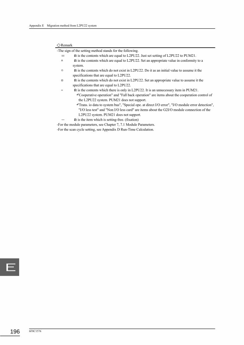
Appendix E Migration method from L2PU22 system
6F8C1576 196
E
Remark ・The sign of the setting method stands for the following.
= :It is the contents which are equal to L2PU22. Just set setting of L2PU22 to PUM21. △ :It is the contents which are equal to L2PU22. Set an appropriate value in conformity to a
system. ○ :It is the contents which do not exist in L2PU22. Do it as an initial value to assume it the
specifications that are equal to L2PU22. □ :It is the contents which do not exist in L2PU22. Set an appropriate value to assume it the
specifications that are equal to L2PU22. × :It is the contents which there is only in L2PU22. It is an unnecessary item in PUM21.
・"Cooperative operation" and "Fall back operation" are items about the cooperation control of the L2PU22 system. PUM21 does not support.
・"Trans. io data to system bus", "Special ope. at direct I/O error", "I/O module error detection", "I/O less test" and "Non I/O less card" are items about the G2I/O module connection of the L2PU22 system. PUM21 does not support.
- :It is the item which is setting-free. (fixation) ・For the module parameters, see Chapter 7, 7.1 Module Parameters. ・For the scan cycle setting, see Appendix D Run-Time Calculation.

Unified Controller nv series type2 light Functional Manual
June 2015 1st Edition
Social Infrastructure Systems Company Industrial Systems & Components Division
72-34, Horikawa-Cho, Saiwai-Ku, Kawasaki 212-8585, Japan
© Toshiba Corporation 2015 All Right Reserved.
No part of this document may be reproduced without the prior written consent of Toshiba.

1576.1.1506