
Type SRC-200-BAC - SyxthSense · Type SRC-200-BAC Model Type Model Description SRC200-BAC Space...
28
Online store: www.syxthsense.com Enquiries: T: 0844 840 3100 F: 0844 840 3200 PS CT2.151 V2.53 - 1/28 SRC-200 Series Climate Controllers with BACnet MS/TP The SRC-200 series controllers have been designed for climate control in room spaces. The controllers have up to two heating and cooling temperature control stages, fan speed control, optional CO2 level and humidity control. The units can be in various climate control applications including VAV, fan coil units and natural ventilation systems. The controllers have 4 analogue 0..10Vdc outputs and two digital outputs that can be configured for heating, cooling, CO2, humidity, maximum VAV demand or maximum fan demand control. The controllers can operate as Proportional Only or as Proportional + Integral Controllers. The analogue outputs can be individually configured for any of the heating/cooling stages, CO2, maximum VAV demand or Humidity control. The digital outputs can be configured as 3-point, PWM (thermic) or On/Off control. The SRC-200CO2 versions have built-in CO2 measurement and the outputs can be controlled based on CO2, maximum VAV demand (temperature and CO2), or maximum Fan demand. The SRC-200RH versions humidity measurement and can be used to increase ventilation when high humidity is present. The controller setpoint can be adjusted -/+3°C (default) by rotating the potentiometer. The display shows comprehensive information on the controller status. With AI options it is possible to monitor/control 0-10V inputs. The controllers have built-in BACnet MS/TP communication for connection to BMS systems but can also operate as stand-alone.. Product sheet CT2.151 Type SRC-200-BAC Model Type Model Description SRC200-BAC Space Climate Controller with Heating and Cooling Outputs, Fan Speed Control, LCD Display, BACnet MS/TP SRC200-CO2-BAC Space Climate Controller with Heating and Cooling Outputs, CO2 Sensor and Control, Fan Speed Control, LCD Display, BACnet MS/TP SRC200-RH-BAC Space Climate Controller with Heating and Cooling Outputs, Relative Humidity Sensor and Control, Fan Speed Control, LCD Display, BACnet MS/TP SRC200-CO2RH-BAC Space Climate Controller with Heating and Cooling Outputs, CO2 Sensor and Control, Relative Humidity Sensor and Control, Fan Speed Control, LCD Display, BACnet MS/TP -PB Push Button Option -SPB Push Button Setpoint Option (Replaces Rotary Potentiometer Setpoint) -NPB Night Mode Push Button (Local Override Option for Night) -LL Light Level and Occupancy Sensor (only available when Rotary Setpoint is not fitted) Note1 -TP No User Setpoint Adjustment (no potentiometer or push button setpoint provided) -BL No Display or User Setpoint Adjustment (Potentiometer or Buttons) fitted, Blank Cover or Cover with Light Sensor -RI2 Extra Resistive Input for Network Measurement Only (device supplied with -SPB option for temp setpoint, no pot) -AI1 Converts RI1 to Analogue 0..10Vdc input, network measurement and/or PI-control Note2 -AI2 Second analogue input for Network Measurement (device supplied with -SPB option for temp setpoint, no pot) Note 3 -RA Alternative Bit Switch Range, Bit Switches 1..7 Used for MAC Address, Bit Switch 8 Used for Baud Rate
Transcript of Type SRC-200-BAC - SyxthSense · Type SRC-200-BAC Model Type Model Description SRC200-BAC Space...

Product sheet CT2.151
Type SRC-200-BAC
SRC-200 Series Climate Controllers with BACnet MS/TP
The SRC-200 series controllers have been designed for climate control in room spaces. The controllers have up to two heating and cooling temperature control stages, fan speed control, optional CO2 level and humidity control. The units can be in various climate control applications including VAV, fan coil units and natural ventilation systems. The controllers have 4 analogue 0..10Vdc outputs and two digital outputs that can be configured for heating, cooling, CO2, humidity, maximum VAV demand or maximum fan demand control. The controllers can operate as Proportional Only or as Proportional + Integral Controllers.
The analogue outputs can be individually configured for any of the heating/cooling stages, CO2, maximum VAV demand or Humidity control. The digital outputs can be configured as 3-point, PWM (thermic) or On/Off control. The SRC-200CO2 versions have built-in CO2 measurement and the outputs can be controlled based on CO2, maximum VAV demand (temperature and CO2), or maximum Fan demand. The SRC-200RH versions humidity measurement and can be used to increase ventilation when high humidity is present.
The controller setpoint can be adjusted -/+3°C (default) by rotating the potentiometer. The display shows comprehensive information on the controller status. With AI options it is possible to monitor/control 0-10V inputs. The controllers have built-in BACnet MS/TP communication for connection to BMS systems but can also operate as stand-alone..
Model Type Model Description
SRC200-BAC Space Climate Controller with Heating and Cooling Outputs, Fan Speed Control, LCD Display, BACnet MS/TP
SRC200-CO2-BAC Space Climate Controller with Heating and Cooling Outputs, CO2 Sensor and Control, Fan Speed Control, LCD Display, BACnet MS/TP
SRC200-RH-BAC Space Climate Controller with Heating and Cooling Outputs, Relative Humidity Sensor and Control, Fan Speed Control, LCD Display, BACnet MS/TP
SRC200-CO2RH-BAC Space Climate Controller with Heating and Cooling Outputs, CO2 Sensor and Control, Relative Humidity Sensor and Control, Fan Speed Control, LCD Display, BACnet MS/TP
-PB Push Button Option
-SPB Push Button Setpoint Option (Replaces Rotary Potentiometer Setpoint)
-NPB Night Mode Push Button (Local Override Option for Night)
-LL Light Level and Occupancy Sensor (only available when Rotary Setpoint is not fitted) Note1
-TP No User Setpoint Adjustment (no potentiometer or push button setpoint provided)
-BL No Display or User Setpoint Adjustment (Potentiometer or Buttons) fitted, Blank Cover or Cover with Light Sensor
-RI2 Extra Resistive Input for Network Measurement Only (device supplied with -SPB option for temp setpoint, no pot)
-AI1 Converts RI1 to Analogue 0..10Vdc input, network measurement and/or PI-control Note2
-AI2 Second analogue input for Network Measurement (device supplied with -SPB option for temp setpoint, no pot) Note 3
-RA Alternative Bit Switch Range, Bit Switches 1..7 Used for MAC Address, Bit Switch 8 Used for Baud Rate
Online store: www.syxthsense.com
Enquiries: T: 0844 840 3100 F: 0844 840 3200 PS CT2.151 V2.53 - 1/28

SyxthSense Ltd
-ND No Display Fitted
SW-DCT-USB Windows Device Configuration Tool with 1.8m USB Cable
Note 1: The LL option disables the external resistive input 1. Note 2: If AI1 option is selected, RI2 (second resistive input) option is no longer availableNote 3: AI2 option requires AI1 option (it is not possible to have a mix of resistive and analogue inputs)
Technical Data
Power Supply Power supply 24Vac/dc -10%/+15% <1VA
Displays and Interfaces LCD LCD Display for Showing Plant Status (Heating/Cooling Mode, Current Temperature, CO2, Humidity, Setpoint, Valve Position, Fan Speed, Day/Night Mode, Amber/Red Alarms)
Setpoint Potentiometer Setpoint Adjust between 18°C and 24°C (limits adjustable)
Option -PB Backlit Multi-Step Push Button with Delay Timer; Can be configured Override the Control Loop Outputs
Option -SPB Setpoint with 2 Push Buttons (adjustable min/max limits) ote: If
this option is selected PB option becomes 3rd button.
Option -NPB Backlit Push Button Night Override (With moon icon printing)
Signal Outputs Analogue Outputs 4 x 0..10V < 5mA
Digital Outputs 2 x 24Vac Triacs; 1A maximum; requires 24Vac Power Supply
Signal Inputs Built-In Sensor 0..50°C (32..122°F) ±0.3°C @ 25°C
Resistive Input 1 1 x External NTC10K3 Sensor (Auto-Detect)
Resistive Input 2 (RI2 Option)
1 x External NTC10K3 Sensor (device supplied with push button setpoint -SPB instead of the setpoint pot)
Analogue Input (AI1 Option) 1 x 0..10Vdc (replaces the resistive input 1)
Analogue Input (AI2 Option) 1 x 0..10Vdc (replaces setpoint pot, the device supplied with -SPB push button setpoint)
Digital Input 2 x Digital Input, Volt-Free Contact, Impedance <1KOhm
Optional Sensing Carbon Dioxide (CO2 Models)
Characteristics Range 0...5000ppm CO2
Accuracy ± 50ppm + 3% of the reading @ 25°C (@77°F)
Technology Auto Calibrating; Patented Non-Dispersive Infrared (NDIR)
Non-Linearity <1% FS
Warm-Up Time <20 seconds
Response Time 2 minutes
Humidity (RH Models)
Range 0..100%rH
Accuracy ±2% rH (within 20..80% rh)
Light Level and Occupancy; Option -LL
Note: If this option is selected RI1 (resistive input) is no longer available and need to be left disconnected - this will also disable the sensor auto-detection.
Range 0..3,000 Lux
Occupancy Infrared Detection (Adjustable Delay)
Communication BACnet Communications
Protocol BACnet MS/TP
Interface RS485; maximum 63 devices
MAC Addressing 0..63 via a bit switch; 0..247 via tool / network
Communication 9k6/19k2/38k4/76k8 Baud; Parity None/Even/Odd, 1 or 2 Stop Bits (baud rate adjustable through bit switch)
Connections Terminal Connections Solid and Stranded Cable; 55° Angle for WiringMaximum Size: 0.05 to 1.5mm2 (EN ISO) / 14 to 30 AWG (UL)Rising Clamp: Size 2.5 x 1.9mm
Environmental Conditions Operating
Temperature 0°C...+50°C (32..122°F)
Humidity 0...95%rh (non-cond.)
Storage
Temperature -30°C...+70°C (-22..158°F)
Humidity 0...95%rh (non-cond.)
Copyright © 2018 SyxthSense Ltd. All rights reserved - 12/2018
PS CT2.151 - 2/28
Online store: www.syxthsense.com
Enquiries: T: 0844 840 3100 F: 0844 840 3200

SyxthSense Ltd
Wiring ConnectionsSRC-200-BAC
24 Vac/dc
0 V Go
G
Y3
Supply24 Vac/dc
0..10Vdc Output (Default: Htg Stage 1) Y1
Y2
0V Common
0..10Vdc Output (Default: Clg Stage 1)
DO2
PWM / On - Off / 3-Point (Htg/Clg/Fan/CO2/%rH)
Go
24 Vac Relay
24 Vac Relay DO1
PWM / On - Off / 3-Point (Htg/Clg/Fan/CO2/%rH)
0..10Vdc Output (Default: Clg Stage 2)
BIT SWITCH
OFF
ON
Bit
Rat
e 1
Bit
Rat
e 21 2 4 8 16 32
NetworkAddress
End of LineTermination
CommsTX Led
RS485 (BACnet MS/TP)A+
B- RS485 (BACnet MS/TP)
0V Common
RI2
External NTC10 (Auto-Detect)RI1
DI1
Optional NTC10 Sensor (RI2 Option)
Digital Input - PIR, Window Switch, Door Switch
DI2
Go
Sof
twar
e P
rogr
amm
ing
Inte
rfac
eY4 0..10Vdc Output (Default: Fan)
Backlit Push Button
Digital Input - PIR, Window Switch, Door Switch
SETPOINTPOTENTIOMETER OROCCUPANCY SENSOR(LL-OPTION)
SetpointUp
SetpointDown
SPB OPTION
PB Push ButtonOption
Wiring Precautions
Switch off the power before any wiring is carried out.
Display: Unplug the LCD display and then wire the power supply and the analogue outputs, if relevant. After the wiring has been completed; plug-in the display and power up the device.
Standards CE Conformity CE Directive 2004/108/EY EN61000-6-3: 2001 (Generic Emission) EN61000-6-1: 2001 (Generic Immunity).
Degree of Protection IP20
Housing Housing Material ABS Plastics, Self Extinguishing
Mounting Wall or Junction Box Mounting, RAL9010 Pure White
Dimensions W86 x H120 x D29mm
Weight 220g
DO1 24Vac Triac; PWM, On/Off; 3-Point Open
DO2 24Vac Triac; PWM, On/Off; 3-Point Close
G 24Vac/dc Power Supply
G0 0V Common
Y1 0..10Vdc Output
Y2 0..10Vdc Output
Y3 0..10Vdc Output
G0 0V Common
Y4 0..10Vdc Output
A+ BACnet MS/TP A+ Connection (RS485)
B- BACnet MS/TP B- Connection (RS485)
G0 0V Common
RI1 External NTC10 Sensor (Auto-detect for main loop)
DI1 Digital Input; PIR Input, Windows/Condensation Switch
RI2 Optional NTC10 Measurement (RI2 Option)
DI2 Digital Input; PIR Input, Windows/Condensation Switch
Copyright © 2018 SyxthSense Ltd. All rights reserved - 12/2018
PS CT2.151 - 3/28
Online store: www.syxthsense.com
Enquiries: T: 0844 840 3100 F: 0844 840 3200

SyxthSense Ltd
NATURAL VE
SC(B%
4-PIPE FAN
SC(%
4-PIPE FAN
Application Examples The below application diagrams show few examples of the SRC200 Climate Controller applications. The controller is highly versatile and can be easily configured for most room heating and cooling applications including fan coil unit control, chilled ceiling and zone heating, VAV pressure dependent control and natural ventilation. Please refer to individual set up pages for further details or contact SyxthSense Sales Team for advice.
Natural VentilationControl
HeatingControl Digital Input
Day Override
SRC200 NATURALVENTILATION CONTROLLER(BUILT-IN CO2 AND %rH OPTION)
0-10Vdc, On/Off, 3-PointPWM
0-10Vdc*
0...10Vdc, On/Off, PWM, 3-Point*
Digital InputNight Override
* 2 x available triacs (digital outputs) can be freely configuredfor any of the control signals
ScalableOutputs
ScalableOutputs
Windows OverridePush Button (Backlit)
Optional Fan Output
NTILATION CONTROL
Digital Input Day Override e.g. PIROR Override Nighte.g. Window/Door
SRC200 HEATING / COOLINGCONTROLLER (WITH BUILT-INCO2 OPTION)
* 2 x available triacs (digital outputs) can be freely configuredfor any of the control signals
CHILLED CEILING AND ZONE HEATING APPLICATION WITH FAN ASSISTED FRESH AIR
Chilled Ceiling Cooling
0-10Vdc, On/Off,3-Point, PWM Thermic*
0-10Vdc FanControl
Heating Control
Fresh Air BoostPush Button (Backlit)
0-10Vdc, On/Off, 3-Point, PWM Thermic*
Digital InputCondensation Switch
KA10 CondensationSwitch
Digital Input Day Override e.g. PIR
RC200 FAN COIL UNITONTROLLERUILT-IN CO2 AND rH OPTION)
Digital Input Night Override e.g. Door/Window Switch
* 2 x available triacs (digital outputs) can be freely configuredfor any of the control signals
COIL UNIT CONTROL WITH 3-SPEED FAN
0-10Vdc, On/Off,3-Point, PWM Thermic*
0-10Vdc FanControl (3-Speed or EC Fan)
FCRY-3 FanRelay Module
TV2TV1
Heating Cooling
0-10Vdc, On/Off,3-Point, PWM Thermic*
Digital Input Day Override e.g. PIR
SRC200 FAN COIL UNITCONTROLLER(BUILT-IN CO2 AND %rH OPTION)
0-10Vdc, PWM Thermic*
Digital Input Night Override e.g. Door/Window Switch
* 2 x available triacs (digital outputs) can be configuredwork as ON/OFF or PWM
TV2TV1
4-PIPE FAN COIL UNIT CONTROL WITH MODULATING EC FAN AND ELECTRIC HEATER
Heating Cooling
0-10Vdc
0-10Vdc EC Fan Control
Electric Heater
On/Off 24Vac Triac
IO-1
RM-2
4VA
CRe
lay
Mo
du
le
16A
Digital Input Day Override e.g. PIR
RC200 FAN COIL UNITONTROLLER
BUILT-IN CO2 AND rH OPTION)
0-10Vdc
Digital Input Night Override e.g. Door/Window Switch
TV2TV1
COIL UNIT CONTROL WITH 2-SPEED FAN
Heating Cooling
0-10Vdc
2-SPEED FAN
Fan Speed 1
IO-1
RM-2
4VA
CRe
lay
Mo
du
le
Fan Speed 2
Digital Input Day Override e.g. PIR
SRC200 FAN COIL UNITCONTROLLER(BUILT-IN CO2 AND %rH OPTION)
Digital Input Night Override e.g. Door/Window Switch
* 2 x available triacs (digital outputs) can be freely configuredfor any of the control signals
AIR-SIDE FAN COIL UNIT CONTROL WITH 3-SPEED FAN
Heating
Cooling
0-10Vdc, On/Off,3-Point, PWM Thermic* 0-10Vdc Fan
Control (3-Speed or EC Fan)
FCRY-3 FanRelay Module
Mid-position =Setpoint
Setpoint Adjustment By rotating the setpoint knob option it is possible to adjust the current temperature control setpoint +/-3°C. The adjustment shifts temperature
CO
NTR
OL
OU
TPU
T
SP= Setpoint100%
SP0%
Measurement- +
ReduceSetpoint
IncreaseSetpoint
setpoint up and down. Via the configuration tool it is possible to adjust the setpoint centre, and the min and max adjustments of the setpoint.
When the potentiometer is rotated the current setpoint is displayed on the screen (in display model), and the backlight is switched on momentarily.
The SPB option provides two push buttons for setpoint instead of the potentiometer. The adjustment shifts the temperature setpoint up or down up to the minimum and maximum allowable setpoint. A configurable parameter (Setpoint Adjust Reset) is available to automatically either reset or retain the current user setpoint adjustment when the setpoint is changed over the network. The user setpoint adjustment can also be reset over the network via a dedicated Binary output object.
Copyright © 2018 SyxthSense Ltd. All rights reserved - 12/2018
PS CT2.151 - 4/28
Online store: www.syxthsense.com
Enquiries: T: 0844 840 3100 F: 0844 840 3200

SyxthSense Ltd
With SPB option Setpoint Adjust Save parameter is available to enabling saving the user setpoint adjustment to non-volatile memory. If this is enabled, after the power-cycle the controller returns to use the latest user adjusted setpoint.
SRC200 User Interface The SRC200 controllers have a built-in backlit LCD that can be used to show the current status of the controller. The display is also used to show number of configuration settings. The images below illustrate different display options.
SetpointKnob
Display IconsHeating Mode
Cooling Mode
Temperature Reading
USER DISPLAY MODES
Current Valve PositionSETPOINT DISPLAYADJUSTMENT(+/-3°C OF SP CENTER)
Day Control
Night Control
Relative Humidity
SETPOINT ADJ IS SHOWED WHEN KNOB IS ROTATED
TEMPERATUREDISPLAY (FAHRENHEIT) 3-SPEED FANSPEED DISPLAYDAY MODE ICONHEATING ICON
ANIMATING FAN
FAN SPEED OPTIONS
MODULATINGFAN SPEED
3-Speed Control
Modulating Fan Speed
TEMPERATURE DISPLAYWITH VALVE POSITION,HEATING,NIGHT
TEMPERATURE DISPLAYWITH VALVE POSITION,COOLING,DAY
FLASHING WHEN COOLING OVERRIDE VIA PUSH BUTTON
ALTERNATING CO2MEASUREMENT ANDHUMIDITY MEASURENT(POSSIBILITY TO SELECTALTERNATING DISPLAY,OR TEMP AND VALVE POS ONLY)
ALARM DISPLAY EXAMPLES
TEMPERATURE AMBER ALARM
FLASHING °C
CO2 REDALARM
FLASHING PPM
PB Option
NPB Option
SR
C-2
00-S
PB
SETPOINT UP button
SETPOINT DOWN button
PUSH button option (optional fanicon print)
SR
C-2
00-P
B-N
PB
LCD Display
The LCD display shows the controller current operation status to the user.
• Temperature, CO2 Level, Humidity Measurement (CO2 model; can be configured to auto-rotate between CO2 and temperature. RH model; configured to auto-rotate between valve/fan position and humidity measurement)
• Current Cooling/Heating Demand with heating and cooling mode icons (Set Info Line to Show the Valve Output)
• No heating or cooling icon if neither heating or cooling stages are active. Note: With PI control the outputs are usually active within the deadzone.
• Day Mode / Night Mode icon• Fan Speed (modulating or A-0-1-2-3; set the Info Line to show Fan Speed)• CO2, Temperature, Humidity Alarm Display (amber/red)
The display can show either the Fan Speed or Valve position. This is configured during the commissioning. If CO2 is fitted, the CO2 reading can be configured to be rotated with the temperature reading. If RH is fitted, the %rH reading can be configured to be rotated with the fan speed/valve position
The user interface includes as standard rotary potentiometer for setpoint adjustment, and optional push buttons (PB override push button/fan speed control, NPB night override). SRC200 controllers with SPB option have two push buttons for setpoint instead of the rotary setpoint.
Copyright © 2018 SyxthSense Ltd. All rights reserved - 12/2018
PS CT2.151 - 5/28
Online store: www.syxthsense.com
Enquiries: T: 0844 840 3100 F: 0844 840 3200
SyxthSense Ltd
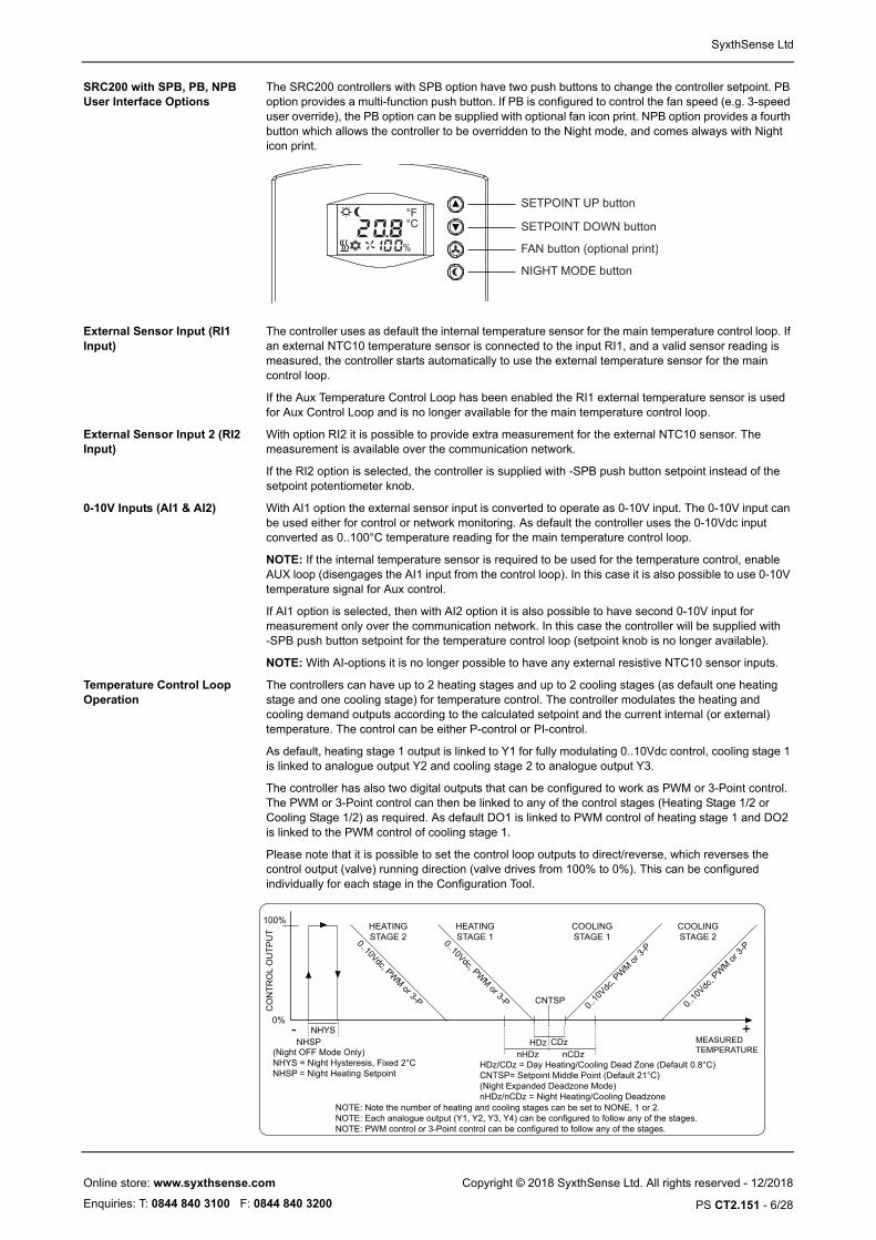
SRC200 with SPB, PB, NPB User Interface Options
The SRC200 controllers with SPB option have two push buttons to change the controller setpoint. PB option provides a multi-function push button. If PB is configured to control the fan speed (e.g. 3-speed user override), the PB option can be supplied with optional fan icon print. NPB option provides a fourth button which allows the controller to be overridden to the Night mode, and comes always with Night icon print.
SETPOINT UP button
SETPOINT DOWN button
FAN button (optional print)
NIGHT MODE button
External Sensor Input (RI1 Input)
The controller uses as default the internal temperature sensor for the main temperature control loop. If an external NTC10 temperature sensor is connected to the input RI1, and a valid sensor reading is measured, the controller starts automatically to use the external temperature sensor for the main control loop.
If the Aux Temperature Control Loop has been enabled the RI1 external temperature sensor is used for Aux Control Loop and is no longer available for the main temperature control loop.
External Sensor Input 2 (RI2 Input)
With option RI2 it is possible to provide extra measurement for the external NTC10 sensor. The measurement is available over the communication network.
If the RI2 option is selected, the controller is supplied with -SPB push button setpoint instead of the setpoint potentiometer knob.
0-10V Inputs (AI1 & AI2) With AI1 option the external sensor input is converted to operate as 0-10V input. The 0-10V input can be used either for control or network monitoring. As default the controller uses the 0-10Vdc input converted as 0..100°C temperature reading for the main temperature control loop.
NOTE: If the internal temperature sensor is required to be used for the temperature control, enable AUX loop (disengages the AI1 input from the control loop). In this case it is also possible to use 0-10V temperature signal for Aux control.
If AI1 option is selected, then with AI2 option it is also possible to have second 0-10V input for measurement only over the communication network. In this case the controller will be supplied with -SPB push button setpoint for the temperature control loop (setpoint knob is no longer available).
NOTE: With AI-options it is no longer possible to have any external resistive NTC10 sensor inputs.
Temperature Control Loop Operation
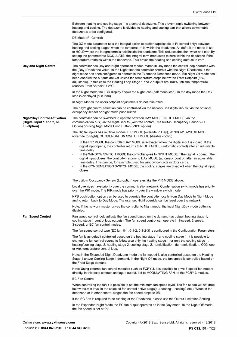
The controllers can have up to 2 heating stages and up to 2 cooling stages (as default one heating stage and one cooling stage) for temperature control. The controller modulates the heating and cooling demand outputs according to the calculated setpoint and the current internal (or external) temperature. The control can be either P-control or PI-control.
As default, heating stage 1 output is linked to Y1 for fully modulating 0..10Vdc control, cooling stage 1 is linked to analogue output Y2 and cooling stage 2 to analogue output Y3.
The controller has also two digital outputs that can be configured to work as PWM or 3-Point control. The PWM or 3-Point control can then be linked to any of the control stages (Heating Stage 1/2 or Cooling Stage 1/2) as required. As default DO1 is linked to PWM control of heating stage 1 and DO2 is linked to the PWM control of cooling stage 1.
Please note that it is possible to set the control loop outputs to direct/reverse, which reverses the control output (valve) running direction (valve drives from 100% to 0%). This can be configured individually for each stage in the Configuration Tool.
CO
NTR
OL
OU
TPU
T HEATINGSTAGE 1
COOLINGSTAGE 1
CNTSP
0..10Vdc, PWM or 3-P
0..10
Vdc, P
WM or
3-P
HDz/CDz = Day Heating/Cooling Dead Zone (Default 0.8°C)CNTSP= Setpoint Middle Point (Default 21°C)(Night Expanded Deadzone Mode)nHDz/nCDz = Night Heating/Cooling Deadzone
HDz MEASURED TEMPERATURE
100%
0%+-
COOLINGSTAGE 2
0..10
Vdc, P
WM or
3-P
HEATINGSTAGE 20..10Vdc, PW
M or 3-P
NOTE: Note the number of heating and cooling stages can be set to NONE, 1 or 2.NOTE: Each analogue output (Y1, Y2, Y3, Y4) can be configured to follow any of the stages.NOTE: PWM control or 3-Point control can be configured to follow any of the stages.
nHDzNHSP
NHYS
(Night OFF Mode Only)NHYS = Night Hysteresis, Fixed 2°CNHSP = Night Heating Setpoint
CDznCDz
Copyright © 2018 SyxthSense Ltd. All rights reserved - 12/2018
PS CT2.151 - 6/28
Online store: www.syxthsense.com
Enquiries: T: 0844 840 3100 F: 0844 840 3200
SyxthSense Ltd
Between heating and cooling stage 1 is a control deadzone. This prevent rapid switching between heating and cooling. The deadzone is divided to heating and cooling part that allows asymmetric deadzones to be configured.
DZ Mode (PI-Control)
The DZ mode parameter sets the integral action operation (applicable to PI-control only) between heating and cooling stages when the temperature is within the deadzone. As default the mode is set to HOLD where the integral term is held inside the deadzone. This reduces the plant wear and tear. By setting the parameter to MODULATE, the integral term modulates to zero within the deadzone if the temperature remains within the deadzone. This drives the heating and cooling outputs to zero.
Day and Night Control The controller has Day and Night operation modes. When in Day mode the control loop operates with the (Day) Deadzone value. In the Night time the controller controls with the Night Deadzone, if the night mode has been configured to operate in the Expanded Deadzone mode. If in Night Off mode has been enabled the outputs are Off unless the temperature drops below the Frost Setpoint (8°C, adjustable). In this case the Heating Loop Stage 1 and 2 outputs are 100% until the temperature reaches Frost Setpoint + 2°C.
In the Night Mode the LCD display shows the Night Icon (half moon icon). In the day mode the Day Icon is displayed (sun icon).
In Night Modes the users setpoint adjustments do not take effect.
The day/night control selection can be controlled via the network, via digital inputs, via the optional occupancy sensor or night mode push button.
Night/Day Control Activation (Digital Input 1 and 2, or LL-Option)
The controller can be switched to operate between DAY MODE / NIGHT MODE via the communication bus, via the digital inputs (volt-free contact), via built-in Occupancy Sensor (-LL Option) or using Night Mode Push Button (-NPB option).
The Digital Inputs has multiple modes; PIR MODE (override to Day), WINDOW SWITCH MODE (override to Night), CONDENSATION SWITCH MODE (disable cooling).
• In the PIR MODE the controller DAY MODE is activated when the digital input is closed. If the digital input opens, the controller returns to NIGHT MODE (automatic control) after an adjustable time delay
• In the WINDOW SWITCH MODE the controller goes to NIGHT MODE if the digital is open. If the digital input closes, the controller returns to DAY MODE (automatic control) after an adjustable time delay. This can be, for example, used for window contacts or door cards.
• In the CONDENSATION SWITCH MODE, the cooling stages are disabled when the digital input closes.
The built-in Occupancy Sensor (LL-option) operates like the PIR MODE above.
Local overrides have priority over the communication network. Condensation switch mode has priority over the PIR mode. The PIR mode has priority over the window switch mode.
NPB push button option can be used to override the controller locally from Day Mode to Night Mode and to return back to Day Mode. The user set Night override can be reset over the network.
Note: If the network master drives the controller to Night mode, the local Night/Day mode button is disabled.
Fan Speed Control Fan speed control logic adjusts the fan speed based on the demand (as default heating stage 1, cooling stage 1 control loop outputs). The fan speed control can operate in 1-speed, 2-speed, 3-speed, or EC fan control modes.
The fan speed control type (EC fan, 0-1, 0-1-2, 0-1-2-3) is configured in the Configuration Parameters.
The fan is as default controlled based on the heating stage 1 and cooling stage 1. It is possible to change the fan control source to follow also only the heating stage 1, or only the cooling stage 1, heating/cooling stage 2, heating stage 2, cooling stage 2, humidification, de-humidification, CO2 loop or Aux temperature control loop.
Note: In the Expanded Night Deadzone mode the fan speed is also controlled based on the Heating Stage 1 and/or Cooling Stage 1 demand. In the Night Off mode, the fan speed is controlled based on the Frost Stage demand.
Note: Using external fan control modules such as FCRY-3, it is possible to drive 3-speed fan motors directly. In this case connect analogue output, set to MODULATING FAN, to the FCRY-3 module.
EC Fan Control
When controlling the fan it is possible to set the minimum fan speed level. The fan speed will not drop below the min level in the selected fan control active stage(s) (heating1, cooling2 etc.). When in the deadzone or in other control stages the fan speed drops to 0%.
If the EC Fan is required to be running at the Deadzone, please use the Output Limitation/Scaling.
In the Expanded Night Mode the EC fan output operates as in the Day mode. In the Night Off mode the fan speed is set at 0%.
Copyright © 2018 SyxthSense Ltd. All rights reserved - 12/2018
PS CT2.151 - 7/28
Online store: www.syxthsense.com
Enquiries: T: 0844 840 3100 F: 0844 840 3200

SyxthSense Ltd
HEATINGSTAGE 1
COOLINGSTAGE 1
SP
100%
0%
FAN CONTROL MODE=EC FAN (MODULATING)
Note: Minimum Fan Speedis configured by Min. ActiveLevel Setting. Max level can be set by scaling the analogue output.
If FAN CONTROLMODE is EC FAN then the fan output is following the control output based on selection*
CO
NTR
OL
LOO
P O
UTP
UT
HEATINGSTAGE 1
COOLINGSTAGE 1
SPHDz+CDz
100%
0%
FAN CONTROL MODE =1-SPEED, 2-SPEED OR 3-SPEED
Speed 1 - 33%
Speed 2 - 66%
Speed 3-99%
If FAN CONTROL MODE is 1-Speed, 2-speed or 3-speed the digital fan outputs are switched ONat switching points of the control loop output.(Heating Stage 1, Cooling Stage 1) Switching points have 5% hysteresis.
Speed 1 - 33%
Speed 2 - 66%
Speed 2 - 99%
Note *: The fan speed can be decided based on Heating Stage 1, Cooling Stage 1,Heating/Cooling Stage1, Heating/Cooling Stage2, Heating Stage 2, Cooling Stage 2,CO2 Loop, Humidification, Dehumidification, Auxiliary Loop or Push Button
Min FanSpeedMIN FAN
SPEED
In the Deadzone fan speed is 0%.HDz+CDz
Fan Speed Control Button (PB Option)
The SRC-200 controllers with PB push button option can be supplied with fan icon printing. The push button can then be configured to override the fan speed control
Example: The PB mode is configured for "Stepped", number of steps is "3" and Push Button Boost target is "fan control loop". If the Push Button Off Delay has been set 0, the user override is active until it has been cancelled, otherwise the delay off time applies.
FANbutton
BY PRESSING THE FAN BUTTONTHE SCREEN ROTATESBETWEEN FAN SPEED OPTIONS
CANCEL = SET AUTO
SWITCH FANOFF (0%)
SET SPEEDTO 2/3 (66%)
SET SPEEDTO FULL (100%)
SET SPEEDTO 1/3 (33%)
Air-Side Control Logic Air-side control is implemented by combining the Heating Stage1 and Cooling Stage 1 demands. As such to use air-side the number of heating stages must be set to 1 or more and the number of cooling stages must be set to 1 or more. In normal operation the stage direction for heating stage 1 and cooling stage 1 should be set the same.
CONTROL OUTPUT HEATING
STAGE 1COOLINGSTAGE 1
MEASURED TEMPERATURE
100%
0%+-
COOLINGSTAGE 2
HEATINGSTAGE 2
NOTE: Number of heating and cooling stages must be set to 1 or more.NOTE: Heating Stage 1 and Cooling Stage 1 direction must be set the same for the air-side control to work (e.g. both reverse).NOTE: Each analogue output (Y1, Y2, Y3, Y4) can be configured to follow air-side control (combined htg stage 1 and clg stage 1).NOTE: PWM control or 3-Point control can be configured to follow air-side control (combined htg stage 1 and clg stage 1).
50%
AIR-SIDE CONTROL (COMBINED HEATING AND COOLING STAGE 1)
CNTSP
HDz/CDz = Day Heating/Cooling Dead Zone (Default 0.8°C)CNTSP= Setpoint Middle Point (Default 21°C)(Night Expanded Deadzone Mode)nHDz/nCDz = Night Heating/Cooling Deadzone
HDznHDz
CDznCDz
Copyright © 2018 SyxthSense Ltd. All rights reserved - 12/2018
PS CT2.151 - 8/28
Online store: www.syxthsense.com
Enquiries: T: 0844 840 3100 F: 0844 840 3200

SyxthSense Ltd
Note: The effective proportional band of the Air-side control is twice that of the Heating2 and Cooling2 stages due to the fact there is only one proportional band setting for all stages.
CO2 Sensor Control Loop Operation (SRC200-CO2 Models)
The CO2 models can measure and control the CO2 level. This can then be used in demand based control applications. The CO2 control output can then be configured to linked to any of the physical control outputs Y1, Y2, Y3 or Y4.
CO
NTR
OL
OU
TPU
T
CO2 Con
trol
SP= Setpoint e.g. 800ppmPB = Proportional Band
100%
PBe.g 400ppmSP
0%
CO2 Level- +
0 ppm
2000 ppm
LOOP OUTPUT
The CO2 control loop output corresponds to the CO2 setpoint and the CO2 proportional band. If configured as Direct Control (typical), then if the CO2 level increases above the setpoint the loop output starts to modulate to 100%. When the CO2 level is the amount of the Proportional Band above the setpoint, the loop output is 100%. The configuration is done via the configuration parameters. The CO2 control loop can also be configured to operate as Proportional + Integral control by changing the Integral Action Time from 0 to a required value.
In the Night Off mode the CO2 loop output is set to 0%. In the Expanded Deadzone Night mode the CO2 loop operates as in the day mode.
NOTE: CO2 measurement is enabled by inserting CO2 link jumpers (two) on the programming header. As default these are fitted (See programming interface section for further details).
Auxiliary Control Loop The SRC controllers have auxiliary (temperature) control loop option. When activated, the auxiliary loop uses the RI1
CO
NTR
OL
OU
TPU
T
CO2 Con
trol
SP= Setpoint e.g. 800ppmPB = Proportional Band
100%
PBe.g 400ppmSP
0%
CO2 Level- +
0 ppm
2000 ppm
LOOP OUTPUT
CO
NTR
OL
OU
TPU
TDire
ct
SP= Setpoint e.g. 20°C
100%
Proportional Bande.g 5°CSP
0% - +
Temperature °C
LOOP OUTPUT
Reverse
NTC10 temperature reading to calculate the required control output.
The auxiliary loop can be configure to operate direct or reverse.
Note: If auxiliary loop is not activated, the RI1 is used for the main temperature control loop automatically (auto-detect).
If LL-option is ordered RI1 is no longer available. In this case the AUX loop will use RI2 input (option).
When AI1 option is fitted and the auxiliary control loop is enabled, the control loop can be used for 0-10V control. The setpoint and proportional band corresponds to the 0-100% input range. This can be used e.g. in pressure control.
High/Low Limit Control for Auxiliary Control Loop (Reset Control - Requires RI2 Option)
The temperature input RI2 can be used as the high/low limit sensor for the Auxiliary control loop providing high limit and/or low limit control. In high limit control, if the external temperature exceeds the High Limit setpoint, the main control setpoint is reduced by the amount set in the Limit Ratio per degree. E.g. if the Limit Ratio is 2, every degree that the external temperature exceeds the High Limit setpoint, the target (setpoint) is reset by 2 degrees.
The Low Limit control works in reverse. If the external temperature drops below the Low Limit setpoint, the main control setpoint is increased by the amount of the ratio for every degree below the Low Limit setpoint.
The setpoint reset amount follows the formula:-
Setpoint_Reset = (Limit_Setpoint - Temperature ) * Limit_Ratio
Note: The limit function is enabled by setting the Limit Ratio parameter (as default 0.0 = disabled).
Note: The limit function is not available with the LL-option.
CO2 Measurement Auto-Calibration
The CO2 sensor has automatic auto-calibration feature. This feature monitors the background CO2 level over the calibration period (8 days), and calibrates the CO2 level to the lowest point measured during this period. The sensors are supplied as factory calibrated to the typical background levels. After powering up the sensor, the sensor carries out initial calibration within 1 day after which the CO2 level is calibrated every 8 days automatically.The auto calibration logic virtually eliminates the need for manual calibration in applications where the indoor CO2 drops to outside levels during unoccupied periods.
NOTE: If the CO2 sensor is fitted in spaces where the background level does not drop close to the typical background level (= fresh air) of 400ppm (e.g. greenhouses) it is essential that the auto-calibration feature is disabled during the commissioning.
VAV Maximum Demand Application
Each of the analogue outputs can also be configured as "Maximum VAV Demand". In this case the corresponding output (Y1, Y2, Y3, Y4) takes the maximum of the CO2 Loop and Cooling Temperature Loop demand output. This is typically used in demand based ventilation (VAV) to control fresh air
Copyright © 2018 SyxthSense Ltd. All rights reserved - 12/2018
PS CT2.151 - 9/28
Online store: www.syxthsense.com
Enquiries: T: 0844 840 3100 F: 0844 840 3200

SyxthSense Ltd
damper when there is either demand for more fresh air, or demand for temperature cooling (typically fresh air cools down the room space).
Maximum Fan Demand Each of the analogue outputs can be configured ad "Maximum Fan Demand". In this configuration the corresponding output (Y1, Y2, Y3, Y4) takes the maximum demand of the CO2 Control Loop and Fan Speed Control Loop. This can provide fan speed boost at high CO2 level and when the fan speed temperature loop has increased the demand.
Humidity Control Loop Operation (SRC-200RH)
The RH models can measure and control the relative humidity level. This can then be used in demand based control applications to increase the fresh air supply e.g. in the high humidity conditions. The control loop has both de-humidification and humidification outputs that can be linked to any of the physical control outputs Y1, Y2, Y3 or Y4. The direction of the both outputs can also be reversed to driver the actuators 100-
CO
NTR
OL
OU
TPU
T
De-hum
idific
ation
SP= Setpoint e.g. 50%rH
100%
Proportional Bande.g 5%rHSP
0%
Humidity %rH
- +0%rH
100%rH
LOOP OUTPUT
Humidification
0% instead of 0-100%.
Output Scaling / Output Limitation
Each of the analogue outputs (Y1,Y2,Y3,Y4) can have
• Output minimum voltage (percentage)• Output maximum voltage (percentage)The connected control loop output 0..100%is then scaled from minimum voltage to maximum voltage.
For example in the EC fan control, if the fan is required to run always at minimum level, the minimum control output voltage can set to 10% (1V) and the maximum output 70% (7V). In this case the output is 1V when the control loop output is less than 10% and the output is 7V when the control loop output is more than 70%. This allows maximum noise levels to be limited and the fan to have a minimum fan speed. In this example the fan is running at 10% within the deadzone. If the fan is required to be off in the deadzone, please use the Min Active Level in the Fan Speed Control section.
The values are available via the communication network from network master read/write. This allows them to be used e.g. in the natural ventilation application limit the window damper position to different values in winter and summer.
Digital Output Triac Operating Modes, (Thermic Control, 3-Point Control, On/Off Control, Fan Control)
The digital outputs (24Vac Triacs that switch 24Vac to 0V) can be configured to operate as 3-point control, as PWM control (pulse width modulation control) or as On/Off control. They can also be configured as outputs to fan speed control (when 1-speed or 2-speed mode selected). The type of the control is selected via the configuration parameters. If the 3-point actuator mode is selected, the controller modulates the DO1 on when valve is required to be opened and DO2 when the valve is required to be closed. The 3-point operation can be configured to follow any of the heating/cooling stages, CO2 control loop, humidity control loops, air-side control or Maximum VAV/FAN.
It is also possible to reverse the output operation by reversing the corresponding loop output.
When the 3-point output is driven fully open or closed, the output is driven against the edge for a "run on" period (default 6 seconds) and this will be repeated every 10 minutes. The run on time time adjustable via the configuration parameters and this behaviour can be disabled completely by setting the run on time to 0.
If PWM actuator is used the duty cycle is 30 seconds as default (configurable via the tool). E.g. if the output is at 50% then the output is ON for 15 seconds and OFF for 15 seconds.
If the PWM mode has been set to On/Off, then the corresponding digital output is switched ON at the Max Level (default 100%) and are switched OFF at the Min level (default 0%).
Note: Please note digital outputs switch to 0V (24Vac is switched to 0V through the triac).
By setting the Analogue Output Y1, Y2, Y3, Y4 to 3-Point Open or 3-Point Close, the analogue output emulates the digital output. If the 3-point logic drives open, and if the analogue output is set to 3-Point Open, the analogue output is set 10V when opening, otherwise 0V. If the 3-point logic drives close, and if the analogue output is set to 3-Point Close, the analogue output is set 10V when closing, otherwise 0V. This can be used with natural ventilation wiring center to drive window actuators.
The 3-point actuator can have two modes, Linear and Stepped. In Linear Mode the 3-point output operates as standard 3-point control. In Stepped Mode the 3-point loop output will not change until the demand has exceeded the configured step amount. This allows the 3-point loop output to be configured to provide e.g. only output values of 0-25-50-75-100%. This reduces the wear and tear on the Windows actuators. The number of steps is defined by the "Push Button Steps" parameter.
Note: DO1/DO2 can also be configured to switch the DI1/DI2 status. The Digital Input Delay parameter applies.
Note: DO1/DO2 can be configured to send Amber/Red or Red alarm condition to the digital output.
Copyright © 2018 SyxthSense Ltd. All rights reserved - 12/2018
PS CT2.151 - 10/28
Online store: www.syxthsense.com
Enquiries: T: 0844 840 3100 F: 0844 840 3200

SyxthSense Ltd
CO2, Humidity, Temperature, Fan and Direct Output Override via Push Button (-PB Option)
Pressing the Push Button, the CO2, Humidity, Fan Speed, Temperature Control Loop Stages or physical Outputs (Y1/Y2/Y3/Y4) can be overridden to 100%, to 0% or to a user adjusted value (Stepped Mode; e.g. 0-25-50-75-100%) for time specified in the override delay parameter. Push Button Operation parameter defines the push button mode (0%, 100% or Stepped). When the override is active, the button backlight in ON.
The override can be cancelled by pressing the button again. In case of stepped mode push button, press again until "CANCEL" is showed on the display.
In case of Open (100%) or Close (0%) Modes, the override can be cancelled by pressing the push button again. In this case the controller returns to normal automatic operation.
In case of Stepped mode, the output is rotated between Cancel and Stepped positions (see below table). Rotating to the Cancel, cancels the override and the controller returns to normal operation.
The possible "Push Button Steps" Configuration Options:
The Push Button Boost target defines which control loop the push button overrides.
NOTE: If the PB (Push Button) option is selected together with SPB option, the push button is the third button down on the controller. As default the push button does not have any printing on it, but on request e.g. fan icon can be printed on it.
Occupancy Sensor (-LL Option)
The LL option offers a low power Passive Infrared Motion sensor with 21mm Fresnel lens designed for HVAC ventilation and
90° 1.5
Unit:m10
OCCUPANCY SENSOR DETECTION RANGE
lighting control applications. The sensor detects human body within its detection range. The LL sensor employs a dual element pyroelectric infrared sensor with advanced electronics circuitry.
The occupancy sensor can be used for:-
• monitoring only (via network)• switching the controller to day mode transition (PIR MODE - see DAY/NIGHT CONTROL ACTI-
VATION section)• boosting heating stage 1 or cooling stage 1 to 100%• boosting fan control loop or CO2 control loop to 100%
NOTE: If the occupancy sensor is configured to override to day mode, when the override is removed, the controller returns to underlying operating mode. E.g. in stand-alone installations it may be
Push Button Steps Description
1 Cancel - 0% - 100%
2 Cancel - 0% - 50% - 100%
3 Cancel - 0% - 33% - 66% - 100%
4 Cancel - 0% - 25% - 50% - 75% - 100%
5 Cancel - 0 % - 20% - 40% - 60% - 80% - 100%
Push Button Target Description
Heating Stage 1 Overrides the Heating Stage 1
Heating Stage 1&2 Overrides the Heating Stage 1&2
Cooling Stage 1 Overrides the Cooling Stage 1
Cooling Stage 1&2 Overrides the Cooling Stage 1&2
Fan Speed Control Overrides the Fan Speed
CO2 Control Demand Overrides the CO2 Control
Humidification Demand Overrides the Humidity Control
De-Humidification Demand Overrides the Dehumidifying Control
Maximum VAV Overrides the Maximum VAV Output (Combined Temperature & CO2 Loop)
Output When Push Button Override is Set to None, the individual outputs can be overridden directly using the push button (Y1,Y2,Y3,Y4,Thermic1,Thermic2,3-Point)
Auxiliary Loop Overrides the Auxiliary Loop Output
Fan No Scale Overrides the Y1-Y4 Output without Min/Max Scaling Applied to the Outputs. Only applies when ModulatingFan or MaximumFan option has been set for the output.
Copyright © 2018 SyxthSense Ltd. All rights reserved - 12/2018
PS CT2.151 - 11/28
Online store: www.syxthsense.com
Enquiries: T: 0844 840 3100 F: 0844 840 3200
SyxthSense Ltd
necessary to e.g. use digital input to switch the unit normally to Night mode in order to achieve Day/Night transition using the occupancy sensor.
Digital Input Operation The controller has two digital inputs that can be used for:-
• Override Day (see DAY/NIGHT CONTROL ACTIVATION section)• Override Night (see DAY/NIGHT CONTROL ACTIVATION section)• Disable Cooling Stages when Active• None (Network Monitoring Only)• Boosting heating stage 1 or cooling stage 1 to 100% (e.g. using external thermostat)• Boosting fan control loop or CO2 control loop to 100%
The digital inputs can also be linked to DO1 output. The digital input delay applies.
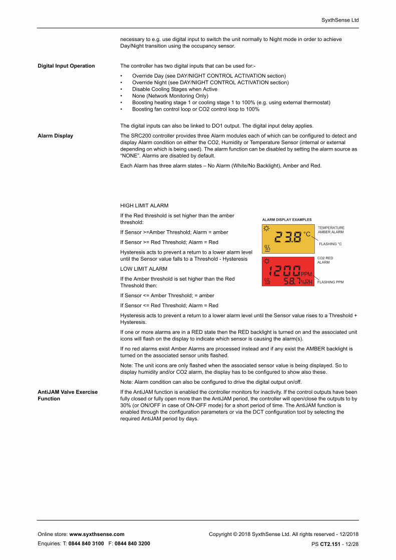
Alarm Display The SRC200 controller provides three Alarm modules each of which can be configured to detect and display Alarm condition on either the CO2, Humidity or Temperature Sensor (internal or external depending on which is being used). The alarm function can be disabled by setting the alarm source as “NONE”. Alarms are disabled by default.
Each Alarm has three alarm states – No Alarm (White/No Backlight), Amber and Red.
HIGH LIMIT ALARM
If the Red threshold is set higher than the amber threshold:
ALARM DISPLAY EXAMPLES
TEMPERATURE AMBER ALARM
FLASHING °C
CO2 REDALARM
FLASHING PPM
If Sensor >=Amber Threshold; Alarm = amber
If Sensor >= Red Threshold; Alarm = Red
Hysteresis acts to prevent a return to a lower alarm level until the Sensor value falls to a Threshold - Hysteresis
LOW LIMIT ALARM
If the Amber threshold is set higher than the Red Threshold then:
If Sensor <= Amber Threshold; = amber
If Sensor <= Red Threshold; Alarm = Red
Hysteresis acts to prevent a return to a lower alarm level until the Sensor value rises to a Threshold + Hysteresis.
If one or more alarms are in a RED state then the RED backlight is turned on and the associated unit icons will flash on the display to indicate which sensor is causing the alarm(s).
If no red alarms exist Amber Alarms are processed instead and if any exist the AMBER backlight is turned on the associated sensor units flashed.
Note: The unit icons are only flashed when the associated sensor value is being displayed. So to display humidity and/or CO2 alarm, the display has to be configured to show also these.
Note: Alarm condition can also be configured to drive the digital output on/off.
AntiJAM Valve Exercise Function
If the AntiJAM function is enabled the controller monitors for inactivity. If the control outputs have been fully closed or fully open more than the AntiJAM period, the controller will open/close the outputs to by 30% (or ON/OFF in case of ON-OFF mode) for a short period of time. The AntiJAM function is enabled through the configuration parameters or via the DCT configuration tool by selecting the required AntiJAM period by days.
Copyright © 2018 SyxthSense Ltd. All rights reserved - 12/2018
PS CT2.151 - 12/28
Online store: www.syxthsense.com
Enquiries: T: 0844 840 3100 F: 0844 840 3200

SyxthSense Ltd
Controller Configuration via Software Configuration Tool
The controller parameter options can be configured either via the Device Configuration Tool software or via the Modbus parameters. The DCT tool is connected via the PC USB cable to the programming header of the controller as shown on the image below
CO
2LI
NK
PRO
G
Programming HeaderConnections
USB / BLUETOOTH CABLE
PRO
G
ENABLE CO2MEASUREMENT
USB PROGRAMMINGCABLE CONNECTOR
PRO
GUSB PROGRAMMING CABLEWhite
GreenBlack
ProgrammingHeader
Red
.
The correct process for connecting the controller via the USB is as follows:-
• Disconnect USB Connector from PC• Disconnect the Controller from Power• Plug-In the 4-Way Connector to the Sensor• Connect the USB to the PC• Power Up the Controller
NOTE: Always disconnect USB from PC before plugging the cable into the controller.
Common Parameters
Parameter Name Description
Defaults Reloads the default configuration from the sensor non-volatile memory. Note: All modified settings are lost.
Reset Performs soft reset of the controller. Apply after major changes.
Read Reads the controller data.
Write Writes the new settings to the controller (automatically stored in the non-volatile memory)
COM Port Select the COM port for the USB Cable or Bluetooth. USB cable driver must be installed in order the Serial to TTL connection to operate.
Copyright © 2018 SyxthSense Ltd. All rights reserved - 12/2018
PS CT2.151 - 13/28
Online store: www.syxthsense.com
Enquiries: T: 0844 840 3100 F: 0844 840 3200
SyxthSense Ltd
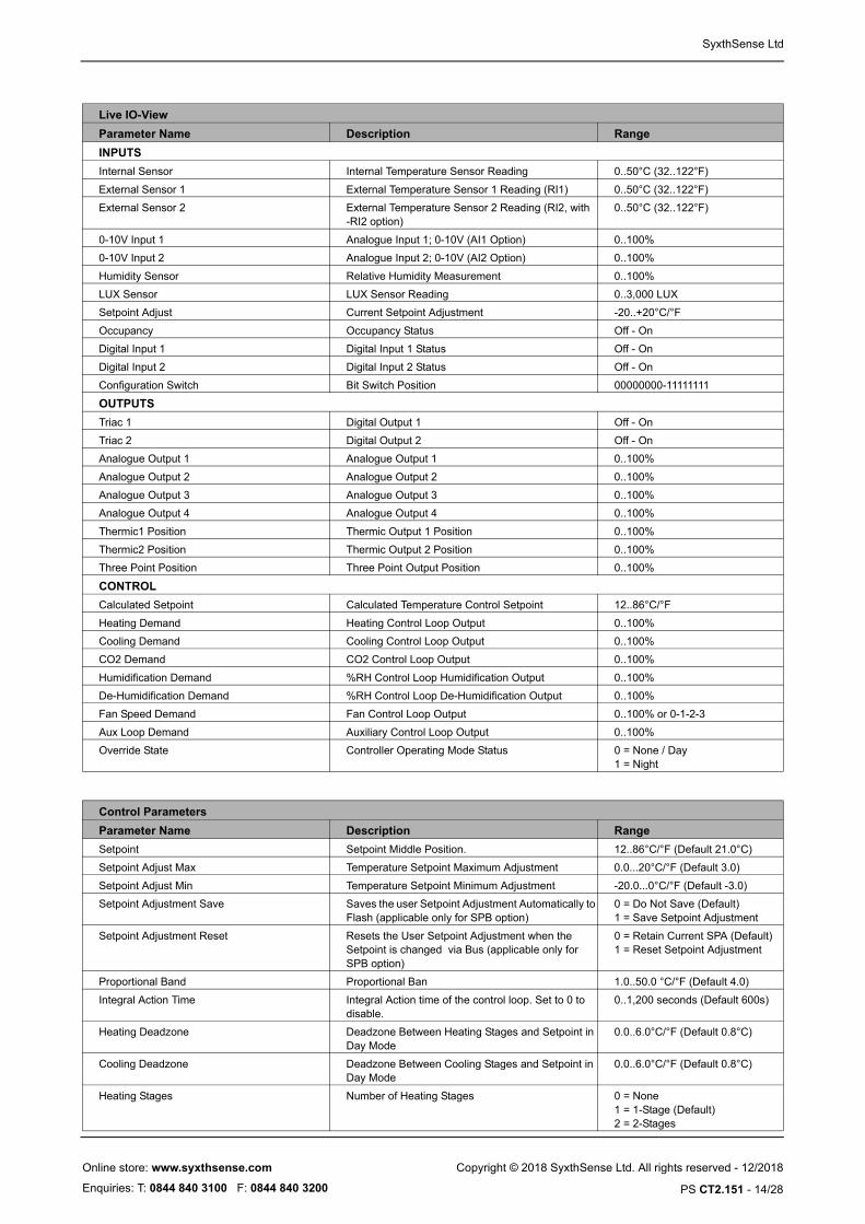
Live IO-View
Parameter Name Description Range
INPUTS
Internal Sensor Internal Temperature Sensor Reading 0..50°C (32..122°F)
External Sensor 1 External Temperature Sensor 1 Reading (RI1) 0..50°C (32..122°F)
External Sensor 2 External Temperature Sensor 2 Reading (RI2, with -RI2 option)
0..50°C (32..122°F)
0-10V Input 1 Analogue Input 1; 0-10V (AI1 Option) 0..100%
0-10V Input 2 Analogue Input 2; 0-10V (AI2 Option) 0..100%
Humidity Sensor Relative Humidity Measurement 0..100%
LUX Sensor LUX Sensor Reading 0..3,000 LUX
Setpoint Adjust Current Setpoint Adjustment -20..+20°C/°F
Occupancy Occupancy Status Off - On
Digital Input 1 Digital Input 1 Status Off - On
Digital Input 2 Digital Input 2 Status Off - On
Configuration Switch Bit Switch Position 00000000-11111111
OUTPUTS
Triac 1 Digital Output 1 Off - On
Triac 2 Digital Output 2 Off - On
Analogue Output 1 Analogue Output 1 0..100%
Analogue Output 2 Analogue Output 2 0..100%
Analogue Output 3 Analogue Output 3 0..100%
Analogue Output 4 Analogue Output 4 0..100%
Thermic1 Position Thermic Output 1 Position 0..100%
Thermic2 Position Thermic Output 2 Position 0..100%
Three Point Position Three Point Output Position 0..100%
CONTROL
Calculated Setpoint Calculated Temperature Control Setpoint 12..86°C/°F
Heating Demand Heating Control Loop Output 0..100%
Cooling Demand Cooling Control Loop Output 0..100%
CO2 Demand CO2 Control Loop Output 0..100%
Humidification Demand %RH Control Loop Humidification Output 0..100%
De-Humidification Demand %RH Control Loop De-Humidification Output 0..100%
Fan Speed Demand Fan Control Loop Output 0..100% or 0-1-2-3
Aux Loop Demand Auxiliary Control Loop Output 0..100%
Override State Controller Operating Mode Status 0 = None / Day1 = Night
Control Parameters
Parameter Name Description Range
Setpoint Setpoint Middle Position. 12..86°C/°F (Default 21.0°C)
Setpoint Adjust Max Temperature Setpoint Maximum Adjustment 0.0...20°C/°F (Default 3.0)
Setpoint Adjust Min Temperature Setpoint Minimum Adjustment -20.0...0°C/°F (Default -3.0)
Setpoint Adjustment Save Saves the user Setpoint Adjustment Automatically to Flash (applicable only for SPB option)
0 = Do Not Save (Default)1 = Save Setpoint Adjustment
Setpoint Adjustment Reset Resets the User Setpoint Adjustment when the Setpoint is changed via Bus (applicable only for SPB option)
0 = Retain Current SPA (Default)1 = Reset Setpoint Adjustment
Proportional Band Proportional Ban 1.0..50.0 °C/°F (Default 4.0)
Integral Action Time Integral Action time of the control loop. Set to 0 to disable.
0..1,200 seconds (Default 600s)
Heating Deadzone Deadzone Between Heating Stages and Setpoint in Day Mode
0.0..6.0°C/°F (Default 0.8°C)
Cooling Deadzone Deadzone Between Cooling Stages and Setpoint in Day Mode
0.0..6.0°C/°F (Default 0.8°C)
Heating Stages Number of Heating Stages 0 = None1 = 1-Stage (Default)2 = 2-Stages
Copyright © 2018 SyxthSense Ltd. All rights reserved - 12/2018
PS CT2.151 - 14/28
Online store: www.syxthsense.com
Enquiries: T: 0844 840 3100 F: 0844 840 3200

SyxthSense Ltd
Heating Stage 1 Direction Heating Stage 1 Direction 0 = Reverse (Default)1 = Direct
Heating Stage 2 Direction Heating Stage 2 Direction 0 = Reverse (Default)1 = Direct
Cooling Stages Number of Cooling Stages 0 = None1 = 1-Stage (Default)2 = 2-Stages
Cooling Stage 1 Direction Cooling Stage 1 Direction 0 = Reverse 1 = Direct (Default)
Cooling Stage 2 Direction Cooling Stage 2 Direction 0 = Reverse 1 = Direct (Default)
Night Mode Night Control Mode 0 = Expanded Deadzone (Default)1 = Night OFF Mode
Relaxed Heating Deadzone Deadzone Between Heating Stages and Setpoint in Night Mode (Expanded Deadzone Mode)
0.0..40.0°C/°F (Default 3.0°C)
Relaxed Cooling Deadzone Deadzone Between Cooling Stages and Setpoint in Night Mode (Expanded Deadzone Mode)
0.0..40.0°C/°F (Default 3.0°C)
Night Frost Setpoint Night Frost Setpoint (Night OFF Mode) 0.0...71.0°C/°F (Default 8.0°C)
DZ Mode Integral Action Operation in Deadzone 0 = Hold (Default)1 = Modulate
CO2 CONTROL
CO2 Control Setpoint CO2 Setpoint 0..5000ppm (Default 1,000 ppm)
CO2 Proportional Band CO2 Proportional Band 10..5000 ppm (Default = 300 ppm)
CO2 Control Integral Action Integral Action time of the CO2 control loop. Set to 0 to disable.
0..10,000 seconds (Default 0)
Output Direction Direction of the CO2 control actuator. 0 = Reverse Acting1 = Direct Acting (Default)
HUMIDITY
Humidity Control Setpoint Humidity Setpoint 0.0...100.0 %rH (Default 50%)
Humidity Proportional Band Humidity Proportional Band 1.0...100.0 %rH (Default 20.0%)
Humidity Control Integral Action Integral Action time of the humidity control loop. Set to 0 to disable.
0..10,000 seconds (Default 0)
Humidification Output Direction Direction of the humidification output (actuator direction, Direct = 0..100%, Reverse = 100..0%).
0 = Reverse Acting1 = Direct Acting (Default)
De-Humidification Output Direction Direction of the dehumidification output (actuator direction, Direct = 0..100%, Reverse = 100..0%).
0 = Reverse Acting1 = Direct Acting (Default)
FAN SPEED CONTROL
Fan Speed Mode Selection Selecting the Fan Speed Mode 0 = 0..100% Modulating1 = 0 - 12 = 0 - 1 - 2 (default)3 = 0 - 1 - 2 - 34 = None
Fan Speed By Fan Speed Control Source 0 = Heating 1 and Cooling 1 Stage (Default)1 = Heating Stage1 2 = Cooling Stage 13 = Heating and Cooling Stage 24 = Heating Stage 25 = Cooling Stage 26 = CO27 = Humidification8 = De-humidification9 = Auxiliary Loop10 = Push Button Boost
Min Active Level Fan Speed Minimum Active Level 0...100 %rH (Default 20%)
AUXILIARY CONTROL LOOP
Aux Control Setpoint Aux Loop Setpoint 12..86°C/°F (Default 21.0°C)
Aux Proportional Band Aux Loop Proportional Band 1.0..50.0 °C/°F (Default 4.0)
Aux Control Integral Action Integral Action time of the Aux control loop. Set to 0 to disable.
0..1,200 seconds (Default 600s)
Output Direction Direction of the CO2 control actuator. 0 = Reverse Acting (Default)1 = Direct Acting
Control Parameters
Parameter Name Description Range
Copyright © 2018 SyxthSense Ltd. All rights reserved - 12/2018
PS CT2.151 - 15/28
Online store: www.syxthsense.com
Enquiries: T: 0844 840 3100 F: 0844 840 3200

SyxthSense Ltd
Enable Aux Loop Enables Auxiliary Control Loop (Activates RI1) 0 = Disabled (Default)1 = Enabled
High Limit Setpoint High Limit Control Setpoint 0.0..95.0 °C/°F (Default 36.0)
Low Limit Setpoint Low Limit Control Setpoint 0.0..95.0 °C/°F (Default 16.0)
Setpoint Adj Ratio Limit Control Setpoint Adjustment Ratio 0.0..5.0 (Default 0.0)
Control Parameters
Parameter Name Description Range
Inputs / Outputs
Parameter Name Description Range
INPUTS
Internal Sensor Offset One Point Internal Temperature Calibration Field -10.0..+10.0°C/°K(Default 0°C)
External Sensor 1 Offset One Point External Temperature Calibration Field, RI1
-10.0..+10.0°C/°K(Default 0°C)
External Sensor 2 Offset One Point External Temperature Calibration Field, RI2
-10.0..+10.0°C/°K(Default 0°C)
CO2 Sensor Offset CO2 Sensor Calibration -500...+500 ppm
Humidity Sensor Offset Humidity Sensor Calibration -5...+5%rH
DI1 Function Digital Input 1 Function 0 = Override Day (PIR Mode) - Default1 = Override Night (Windows Switch Mode)2 = Disable Cooling (Condensation Switch Mode)3 = None4 = Boost Heating Stage 15 = Boost Cooling Stage 16 = Boost Fan Loop7 = Boost CO2 Loop8 = Boost Aux.
DI1 Delay Delay Time Setting for Digital Input 1 0..28800 Seconds (Default 0s)
DI2 Function Digital Input 2 Function 0 = Override Day (PIR Mode) - Default1 = Override Night (Windows Switch Mode)2 = Disable Cooling (Condensation Switch Mode)3 = None4 = Boost Heating Stage 15 = Boost Cooling Stage 16 = Boost Fan Loop7 = Boost CO2 Loop8 = Boost Aux.
DI2 Delay Delay Time Setting for Digital Input 2 0..28800 Seconds (Default 0s)
Push Button Boost Push Button Boost Target 0 = Heating Stage 1 (Default)1 = Heating Stage 1&22 = Cooling Stage 13 = Cooling Stage 1&24 = Fan Control Loop5 = CO2 Control Loop6 = Humidification7 = De-humidification8 = Maximum VAV9 = Output10 = Auxiliary Loop11 = Fan No Scale
Push Button Off Delay Delay Time Setting for Push Button 0..28800 Seconds (Default 600s) 0 = Permanently On
Push Button Mode Sets the Operation Mode of the Push Button. 0 = 0% (Overrides to 0%)1 = 100% (Overrides to 100%, Default)3 = Stepped (Rotates 0%-25%-50%-75%-100%-Cancel)
Push Button Steps Sets the number of steps when "Stepped Mode" is used with the Push Button.
0..5
Copyright © 2018 SyxthSense Ltd. All rights reserved - 12/2018
PS CT2.151 - 16/28
Online store: www.syxthsense.com
Enquiries: T: 0844 840 3100 F: 0844 840 3200
SyxthSense Ltd
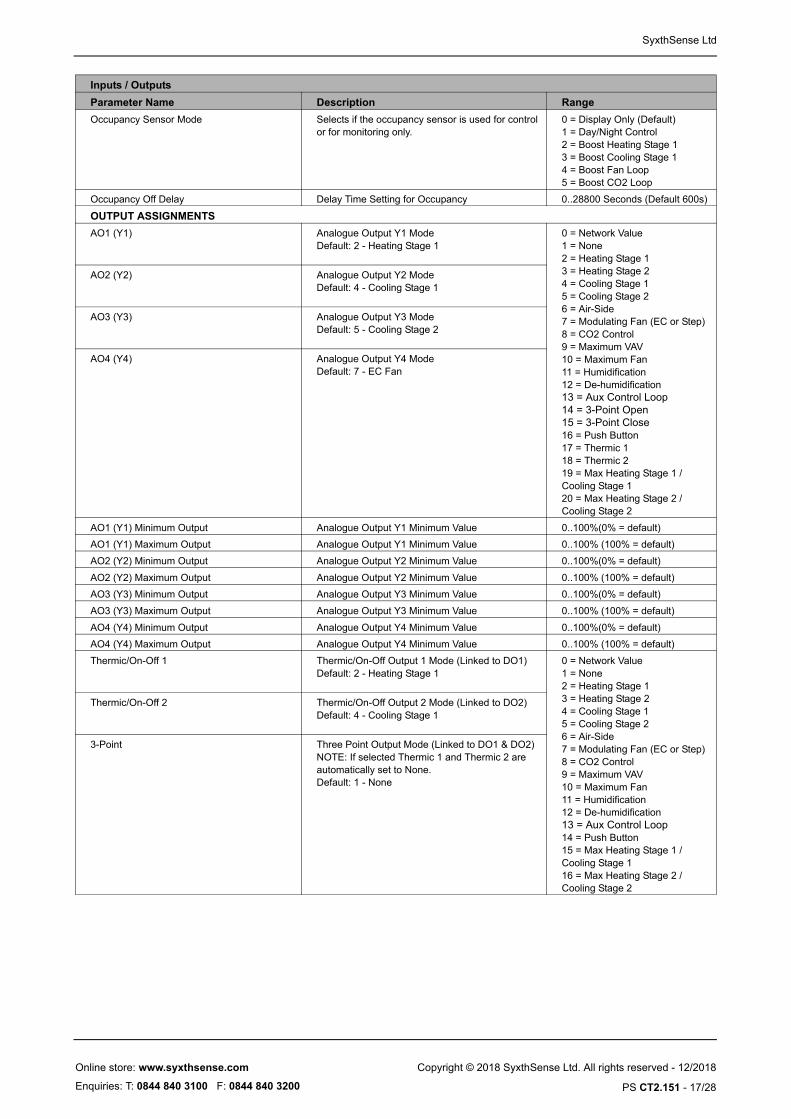
Occupancy Sensor Mode Selects if the occupancy sensor is used for control or for monitoring only.
0 = Display Only (Default)1 = Day/Night Control2 = Boost Heating Stage 13 = Boost Cooling Stage 14 = Boost Fan Loop5 = Boost CO2 Loop
Occupancy Off Delay Delay Time Setting for Occupancy 0..28800 Seconds (Default 600s)
OUTPUT ASSIGNMENTS
AO1 (Y1) Analogue Output Y1 ModeDefault: 2 - Heating Stage 1
0 = Network Value1 = None2 = Heating Stage 1 3 = Heating Stage 24 = Cooling Stage 15 = Cooling Stage 26 = Air-Side7 = Modulating Fan (EC or Step)8 = CO2 Control9 = Maximum VAV10 = Maximum Fan11 = Humidification12 = De-humidification13 = Aux Control Loop14 = 3-Point Open15 = 3-Point Close16 = Push Button17 = Thermic 118 = Thermic 219 = Max Heating Stage 1 / Cooling Stage 120 = Max Heating Stage 2 / Cooling Stage 2
AO2 (Y2) Analogue Output Y2 ModeDefault: 4 - Cooling Stage 1
AO3 (Y3) Analogue Output Y3 ModeDefault: 5 - Cooling Stage 2
AO4 (Y4) Analogue Output Y4 ModeDefault: 7 - EC Fan
AO1 (Y1) Minimum Output Analogue Output Y1 Minimum Value 0..100%(0% = default)
AO1 (Y1) Maximum Output Analogue Output Y1 Minimum Value 0..100% (100% = default)
AO2 (Y2) Minimum Output Analogue Output Y2 Minimum Value 0..100%(0% = default)
AO2 (Y2) Maximum Output Analogue Output Y2 Minimum Value 0..100% (100% = default)
AO3 (Y3) Minimum Output Analogue Output Y3 Minimum Value 0..100%(0% = default)
AO3 (Y3) Maximum Output Analogue Output Y3 Minimum Value 0..100% (100% = default)
AO4 (Y4) Minimum Output Analogue Output Y4 Minimum Value 0..100%(0% = default)
AO4 (Y4) Maximum Output Analogue Output Y4 Minimum Value 0..100% (100% = default)
Thermic/On-Off 1 Thermic/On-Off Output 1 Mode (Linked to DO1)Default: 2 - Heating Stage 1
0 = Network Value1 = None2 = Heating Stage 13 = Heating Stage 24 = Cooling Stage 15 = Cooling Stage 26 = Air-Side7 = Modulating Fan (EC or Step)8 = CO2 Control9 = Maximum VAV10 = Maximum Fan11 = Humidification12 = De-humidification13 = Aux Control Loop14 = Push Button15 = Max Heating Stage 1 / Cooling Stage 116 = Max Heating Stage 2 / Cooling Stage 2
Thermic/On-Off 2 Thermic/On-Off Output 2 Mode (Linked to DO2)Default: 4 - Cooling Stage 1
3-Point Three Point Output Mode (Linked to DO1 & DO2)NOTE: If selected Thermic 1 and Thermic 2 are automatically set to None.Default: 1 - None
Inputs / Outputs
Parameter Name Description Range
Copyright © 2018 SyxthSense Ltd. All rights reserved - 12/2018
PS CT2.151 - 17/28
Online store: www.syxthsense.com
Enquiries: T: 0844 840 3100 F: 0844 840 3200
SyxthSense Ltd
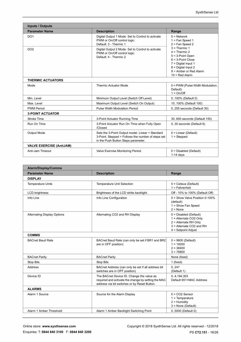
DO1 Digital Output 1 Mode. Set to Control to activate PWM or On/Off control logic.Default: 3 - Thermic 1
0 = Network1 = Fan Speed 12 = Fan Speed 23 = Thermic 14 = Thermic 25 = 3-Point Open6 = 3-Point Close7 = Digital Input 18 = Digital Input 29 = Amber or Red Alarm10 = Red Alarm
DO2 Digital Output 2 Mode. Set to Control to activate PWM or On/Off control logic.Default: 4 - Thermic 2
THERMIC ACTUATORS
Mode Thermic Actuator Mode 0 = PWM (Pulse Width Modulation, Default)1 = On/Off
Min. Level Minimum Output Level (Switch Off Level) 0..100% (Default 0)
Max. Level Maximum Output Level (Switch On Output) 10..100% (Default 100)
PWM Period Pulse Width Modulation Period 0..255 seconds (Default 30)
3-POINT ACTUATOR
Stroke Time 3-Point Actuator Running Time 30..600 seconds (Default 150)
Run On Time 3-Point Actuator Run On TIme when Fully Open /Closed
0..30 seconds (Default 6)
Output Mode Sets the 3-Point Output model. Linear = Standard 3-Point. Stepped = Follows the number of steps set in the Push Button Steps parameter.
0 = Linear (Default)1 = Stepped
VALVE EXERCISE (AntiJAM)
Anti-Jam Timeout Valve Exercise Monitoring Period. 0 = Disabled (Default)1-14 days
Inputs / Outputs
Parameter Name Description Range
Alarm/Display/Comms
Parameter Name Description Range
DISPLAY
Temperature Units Temperature Unit Selection 0 = Celsius (Default)1 = Fahrenheit
LCD brightness Brightness of the LCD white backlight. Off - 10% to 100% (Default Off)
Info Line Info Line Configuration 0 = Show Valve Position 0-100% (default)1 = Show Fan Speed2 = None
Alternating Display Options Alternating CO2 and RH Display 0 = Disabled (Default)1 = Alternate CO2 Only2 = Alternate RH Only3 = Alternate CO2 and RH4 = Setpoint Adjust
COMMS
BACnet Baud Rate BACnet Baud Rate (can only be set if BR1 and BR2 are in OFF position)
0 = 9600 (Default)1 = 192002 = 384003 = 76800
BACnet Parity BACnet Parity None (fixed)
Stop Bits Stop Bits 1 (fixed)
Address BACnet Address (can only be set if all address bit switches are in OFF position)
0..247 (Default 1)
Device ID The BACnet Device ID. Change the value as required and activate the change by setting the MAC address via bit switches or by Reset Button.
0..4,194,303Default 651+MAC Address
ALARMS
Alarm 1 Source Source for the Alarm Display 0 = CO2 Sensor1 = Temperature2 = Humidity3 = None (Default)
Alarm 1 Amber Threshold Alarm 1 Amber Backlight Switching Point 0..5000 (Default 0)
Copyright © 2018 SyxthSense Ltd. All rights reserved - 12/2018
PS CT2.151 - 18/28
Online store: www.syxthsense.com
Enquiries: T: 0844 840 3100 F: 0844 840 3200

SyxthSense Ltd
Parameter Storage The configuration parameters are stored in the non-volatile memory. When the changes are carried out via the Configuration Tool, the parameters are stored in the non-volatile memory when the controller returns to a normal display mode. If the changes are carried out over the network (BACnet), then "NonVol Update" Binary Output Object 4 is required to be forced on to save the changes.
Setting Up BACnet Address and Baud Rate
The SRC BACnet address and the baud rate is normally set through the bit switch. It is also possible to set the address and baud rate over the BACnet communication network.
NOTE: The new settings are activated automatically after approx 5 seconds if the bit switch positions have
not been moved. In this case the controller reset is applied to activate the new settings.
BIT SWITCH
OFF
ON
Bit R
ate
1Bi
t Rat
e 21 2 4 8 16 32
NetworkAddress
BAUD RATE76800
OFF
ON
BAUD RATE38400
OFF
ON
BAUD RATE19200
OFF
ON
BAUD RATE9600 / NETWORK
OFF
ON
Note: When the baud rate set 9600 via the bit switch it is possible to configure the baud rate via network.
SETTING CONTROLLER BAUD RATE
Note: To activate the change the controller requires power cycle.
BIT SWITCH
OFF
ON
Bit R
ate
1Bi
t Rat
e 21 2 4 8 16 32
NetworkAddress
BACNET MAC ID 2
OFF
ON
BACNET MAC ID 9
OFF
ON
Note: If all address bit switches are set OFF, then the BACnet ID can be set over the BACnet.
SETTING CONTROLLER BACNET MAC IDThe BACnet MAC ID is set by using bith switches1 to 6 using binary decoding. Each bitswitch represents the binary value and the address is set by the combination of bit switches. Few examples:
1 2 4 8 16 32 1 2 4 8 16 32
.
BACnet Standard Object Types Supported
No dynamic Creation or Deletion supported. Objects, and object instances, are assigned to fixed functions within the proprietary control application of the product as follows:
Alarm 1 Red Threshold Alarm 1 Amber Backlight Switching Point 0..5000 (Default 0)
Alarm 1 Hysteresis Hysteresis for Alarm 1 0..5000 (Default 0)
Alarm 2 Source Source for the Alarm Display 0 = CO2 Sensor1 = Temperature2 = Humidity3 = None (Default)
Alarm 2 Amber Threshold Alarm 2 Amber Backlight Switching Point 0..5000 (Default 0)
Alarm 2 Red Threshold Alarm 2 Amber Backlight Switching Point 0..5000 (Default 0)
Alarm 2 Hysteresis Hysteresis for Alarm 2 0..5000 (Default 0)
Alarm 3 Source Source for the Alarm Display 0 = CO2 Sensor1 = Temperature2 = Humidity3 = None (Default)
Alarm 3 Amber Threshold Alarm 3 Amber Backlight Switching Point 0..5000 (Default 0)
Alarm 3 Red Threshold Alarm 3 Amber Backlight Switching Point 0..5000 (Default 0)
Alarm 3 Hysteresis Hysteresis for Alarm 3 0..5000 (Default 0)
Alarm/Display/Comms
Parameter Name Description Range
Object Number Of Instances
Instance Assignments
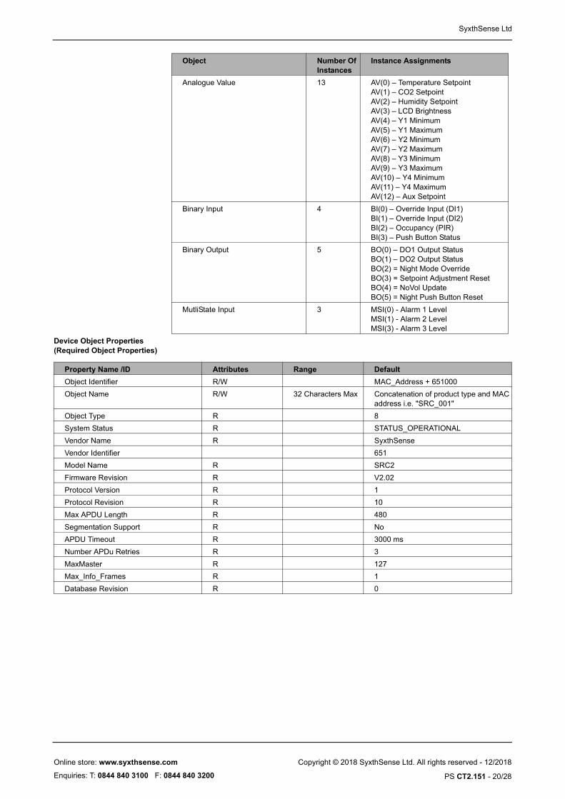
Device Object 1
Analog Input 8 AI(0) – Built-In Temperature SensorAI(1) – External Temp Sensor / AI1AI(2) – Calculated SetpointAI(3) - CO2 SensorAI(4) - Humidity SensorAI(5) - LUX SensorAI(6) - Resistive Input 2 / AI2AI(7) - Aux Calc SP (Aux Loop Setpoint)
Analog Outputs 7 AO(0) – Y1 OutputAO(1) – Y2 OutputAO(2) – Y3 OutputAO(3) - Y4 OutputAO(4) - Thermic1_PositionAO(5) - Thermic2_PositionAO(6) - ThreePoint_Position
Copyright © 2018 SyxthSense Ltd. All rights reserved - 12/2018
PS CT2.151 - 19/28
Online store: www.syxthsense.com
Enquiries: T: 0844 840 3100 F: 0844 840 3200
SyxthSense Ltd
Device Object Properties (Required Object Properties)
Analogue Value 13 AV(0) – Temperature SetpointAV(1) – CO2 SetpointAV(2) – Humidity SetpointAV(3) – LCD BrightnessAV(4) – Y1 MinimumAV(5) – Y1 MaximumAV(6) – Y2 MinimumAV(7) – Y2 MaximumAV(8) – Y3 MinimumAV(9) – Y3 MaximumAV(10) – Y4 MinimumAV(11) – Y4 MaximumAV(12) – Aux Setpoint
Binary Input 4 BI(0) – Override Input (DI1)BI(1) – Override Input (DI2)BI(2) – Occupancy (PIR)BI(3) – Push Button Status
Binary Output 5 BO(0) – DO1 Output StatusBO(1) – DO2 Output StatusBO(2) = Night Mode OverrideBO(3) = Setpoint Adjustment ResetBO(4) = NoVol UpdateBO(5) = Night Push Button Reset
MutliState Input 3 MSI(0) - Alarm 1 LevelMSI(1) - Alarm 2 LevelMSI(3) - Alarm 3 Level
Object Number Of Instances
Instance Assignments
Property Name /ID Attributes Range Default
Object Identifier R/W MAC_Address + 651000
Object Name R/W 32 Characters Max Concatenation of product type and MAC address i.e. "SRC_001"
Object Type R 8
System Status R STATUS_OPERATIONAL
Vendor Name R SyxthSense
Vendor Identifier 651
Model Name R SRC2
Firmware Revision R V2.02
Protocol Version R 1
Protocol Revision R 10
Max APDU Length R 480
Segmentation Support R No
APDU Timeout R 3000 ms
Number APDu Retries R 3
MaxMaster R 127
Max_Info_Frames R 1
Database Revision R 0
Copyright © 2018 SyxthSense Ltd. All rights reserved - 12/2018
PS CT2.151 - 20/28
Online store: www.syxthsense.com
Enquiries: T: 0844 840 3100 F: 0844 840 3200
SyxthSense Ltd
r /
/ AI2
t
T
T
TN
ST
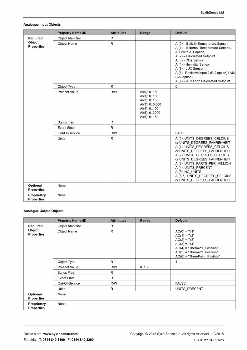
Analogue Input Objects
Analogue Output Objects
Property Name /ID Attributes Range Default
Required Object Properties
Object Identifier R
Object Name R AI(0) – Built-In Temperature SensorAI(1) – External Temperature SensoAI1 (with AI1 option)AI(2) – Calculated SetpointAI(3) - CO2 SensorAI(4) - Humidity SensorAI(5) - LUX SensorAI(6) - Resistive Input 2 (RI2 option) (AI2 option) AI(7) – Aux Loop Calculated Setpoin
Object Type R 0
Present Value R/W AI(0): 0..150AI(1): 0..150AI(2): 0..150AI(3): 0..5,000AI(4): 0..100AI(5): 0..3000AI(6): 0..150
Status Flag R
Event State R
Out-Of-Service R/W FALSE
Units R AI(0): UNITS_DEGREES_CELCIUSor UNITS_DEGREES_FAHRENHEIAI(1): UNITS_DEGREES_CELCIUSor UNITS_DEGREES_FAHRENHEIAI(2): UNITS_DEGREES_CELCIUSor UNITS_DEGREES_FAHRENHEIAI(3): UNITS_PARTS_PER_MILLIOAI(4): UNITS_PRECENTAI(5): NO_UNITSAI(6/7): UNITS_DEGREES_CELCIUor UNITS_DEGREES_FAHRENHEI
Optional Properties
None
Proprietary Properties
None
Property Name /ID Attributes Range Default
Required Object Properties
Object Identifier R
Object Name R AO(0) = “Y1”AO(1) = “Y2”AO(2) = “Y3”AO(3) = “Y4”AO(4) = "Thermic1_Position"AO(5) = "Thermic2_Position"AO(6) = "ThreePoint_Position"
Object Type R 1
Present Value R/W 0..100
Status Flag R
Event State R
Out-Of-Service R/W FALSE
Units R UNITS_PRECENT
Optional Properties
None
Proprietary Properties
None
Copyright © 2018 SyxthSense Ltd. All rights reserved - 12/2018
PS CT2.151 - 21/28
Online store: www.syxthsense.com
Enquiries: T: 0844 840 3100 F: 0844 840 3200

SyxthSense Ltd
TN
point
Analogue Value Objects
Binary Input Objects
Property Name /ID Attributes Range Default
Required Object Properties
Object Identifier R
Object Name R AV(0) – Temperature SetpointAV(1) – CO2 SetpointAV(2) – Humidity SetpointAV(3) – LCD BrightnessAV(4) – Y1 MinimumAV(5) – Y1 MaximumAV(6) – Y2 MinimumAV(7) – Y2 MaximumAV(8) – Y3 MinimumAV(9) – Y3 MaximumAV(10) – Y4 MinimumAV(11) – Y4 MaximumAV(12) – Aux Setpoint
Object Type R 2
Present Value R/W AV(0): 12..86AV(1): 0..5000AV(2): 0..100.0AV(3): 0..10AV(4,11): 0..100.0
Status Flag R
Event State R
Out-Of-Service R/W FALSE
Units R AV(0,12) = UNITS_DEGREES_CELSIUSor UNITS_DEGREES_FAHRENHEIAV(1): UNITS_PARTS_PER_MILLIOAV(2): UNITS_PRECENTAV(3) = NO_UNITSAV(4,11): UNITS_PRECENT
Priority Array R
Relinquish Default R/W AV(0,12) = Nonvol Temperature SetAV(1) = Nonvol CO2 SetpointAV(2) = Nonvol Humidity SetpointAV(3) = Nonvol LCD BrightnessAV(4,11) = Nonvol Min/Max Values
Optional Properties
None
Proprietary Properties
None
Property Name /ID Attributes Range Default
Required Object Properties
Object Identifier R
Object Name R BI(0) = “DI1”BI(1) = "DI2"BI(2) = "Occupancy"BI(3) = "PushButton"
Object Type R 3
Present Value R/W 0..1
Status Flags R
Event State R
Out-Of-Service R/W FALSE
Polarity R/W POLARITY_NORMAL
Active Text R "on"
Inactive Text R "off"
Optional Properties
None
Copyright © 2018 SyxthSense Ltd. All rights reserved - 12/2018
PS CT2.151 - 22/28
Online store: www.syxthsense.com
Enquiries: T: 0844 840 3100 F: 0844 840 3200

SyxthSense Ltd
Binary Output Objects
Multi-State Input Objects
App_Config Objects NOTE: Application Configuration Objects expose the configuration parameters over the BACnet. However please check if your BACnet client can support Proprietary Object types to be able to access these parameters. Alternatively set the configuration parameters through the DCT tool.
Proprietary Properties
None
Property Name /ID Attributes Range Default
Property Name /ID Attributes Range Default
Required Object Properties
Object Identifier R
Object Name R BO(0) = “DO1”BO(1) = “DO2”BO(2) = "Night_Mode_Override"BO(3) = "SPA Reset"BO(4) = "NonVol Update"BO(5) = "Night Push Button Reset"
Object Type R 4
Present Value R/W 0..1
Status Flags R
Event State R
Out-Of-Service R/W FALSE
Polarity R/W POLARITY_NORMAL
Priority Array R
Relinquish Default R/W BINARY_INACTIVE
Active Text R "on"
Inactive Text R "off"
Optional Properties
None
Proprietary Properties
None
Property Name /ID Attributes Range Default
Required Object Properties
Object Identifier R
Object Name R MSI(0) = "Alarm 1 Level"MSI(1) = "Alarm 2 Level"MSI(2) = "Alarm 3 Level"
Object Type R 13
Present Value R/W 1,2,3 (Green, Amber, Red)
Status Flags R
Event State R
Out-Of-Service R/W FALSE
Number-Of-States R 3
Optional Properties
None
Proprietary Properties
None
Property Name /ID Attributes Range Default
Required Object Properties
Object Identifier R proprietary-128
Object Name R/W "App_Config1"
Object Type R proprietary-128
Copyright © 2018 SyxthSense Ltd. All rights reserved - 12/2018
PS CT2.151 - 23/28
Online store: www.syxthsense.com
Enquiries: T: 0844 840 3100 F: 0844 840 3200
SyxthSense Ltd
ode)itch
age 1age 2
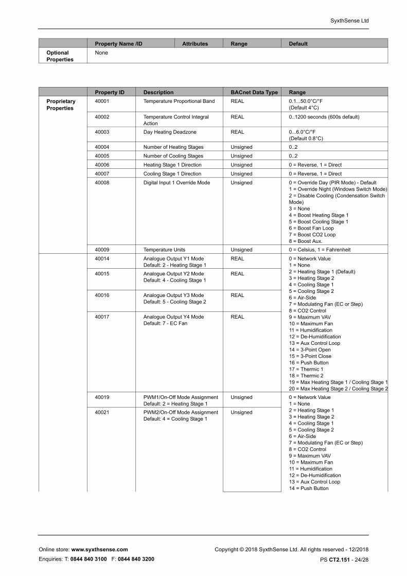
Optional Properties
None
Property Name /ID Attributes Range Default
Property ID Description BACnet Data Type Range
Proprietary Properties
40001 Temperature Proportional Band REAL 0.1...50.0°C/°F(Default 4°C)
40002 Temperature Control Integral Action
REAL 0..1200 seconds (600s default)
40003 Day Heating Deadzone REAL 0...6.0°C/°F(Default 0.8°C)
40004 Number of Heating Stages Unsigned 0..2
40005 Number of Cooling Stages Unsigned 0..2
40006 Heating Stage 1 Direction Unsigned 0 = Reverse, 1 = Direct
40007 Cooling Stage 1 Direction Unsigned 0 = Reverse, 1 = Direct
40008 Digital Input 1 Override Mode Unsigned 0 = Override Day (PIR Mode) - Default1 = Override Night (Windows Switch M2 = Disable Cooling (Condensation SwMode)3 = None4 = Boost Heating Stage 15 = Boost Cooling Stage 16 = Boost Fan Loop7 = Boost CO2 Loop8 = Boost Aux.
40009 Temperature Units Unsigned 0 = Celsius, 1 = Fahrenheit
40014 Analogue Output Y1 ModeDefault: 2 - Heating Stage 1
REAL 0 = Network Value1 = None2 = Heating Stage 1 (Default)3 = Heating Stage 24 = Cooling Stage 15 = Cooling Stage 26 = Air-Side7 = Modulating Fan (EC or Step)8 = CO2 Control9 = Maximum VAV10 = Maximum Fan11 = Humidification12 = De-Humidification13 = Aux Control Loop14 = 3-Point Open15 = 3-Point Close16 = Push Button17 = Thermic 118 = Thermic 219 = Max Heating Stage 1 / Cooling St20 = Max Heating Stage 2 / Cooling St
40015 Analogue Output Y2 ModeDefault: 4 - Cooling Stage 1
REAL
40016 Analogue Output Y3 ModeDefault: 5 - Cooling Stage 2
REAL
40017 Analogue Output Y4 Mode Default: 7 - EC Fan
REAL
40019 PWM1/On-Off Mode AssignmentDefault: 2 = Heating Stage 1
Unsigned 0 = Network Value1 = None2 = Heating Stage 13 = Heating Stage 24 = Cooling Stage 1 5 = Cooling Stage 26 = Air-Side7 = Modulating Fan (EC or Step)8 = CO2 Control9 = Maximum VAV10 = Maximum Fan11 = Humidification12 = De-Humidification13 = Aux Control Loop14 = Push Button
40021 PWM2/On-Off Mode AssignmentDefault: 4 = Cooling Stage 1
Unsigned
Copyright © 2018 SyxthSense Ltd. All rights reserved - 12/2018
PS CT2.151 - 24/28
Online store: www.syxthsense.com
Enquiries: T: 0844 840 3100 F: 0844 840 3200

SyxthSense Ltd
ode)itch
40023 3-Point Mode Assignment Unsigned 0 = Network Value1 = None2 = Heating Stage 1 (Default)3 = Heating Stage 24 = Cooling Stage 1 5 = Cooling Stage 26 = Air-Side7 = Modulating Fan (EC or Step)8 = CO2 Control9 = Maximum VAV10 = Maximum Fan11 = Humidification12 = De-Humidification13 = Aux Control Loop14 = Push Button
40024 3-Point Run Time Unsigned 30..600 Seconds
40025 3-P Run On Time Unsigned 0..30
40026 DO1 Override Mode Unsigned 0 = Network1 = Fan Speed 12 = Fan Speed 23 = Thermic 14 = Thermic 25 = 3-Point Open6 = 3-Point Close7 = Digital Input 18 = Digital Input 29 = Amber or Red Alarm10 = Red Alarm
40027 DO2 Override Mode Unsigned
40028 Internal Sensor One Point Compensation
REAL -10.0..+10.0 °C/°F
40029 External RI1 Sensor One Point Compensation
REAL -10.0..+10.0 °C/°F
40030 Setpoint Adjust Minimum REAL -20.0..0.0 °C/°F
40031 Setpoint Adjust Maximum REAL 0.0..200.0 °C/°F
40032 Digital Input 2 Override Mode Unsigned 0 = Override Day (PIR Mode) - Default1 = Override Night (Windows Switch M2 = Disable Cooling (Condensation SwMode)3 = None4 = Boost Heating Stage 15 = Boost Cooling Stage 16 = Boost Fan Loop7 = Boost CO2 Loop8 = Boost Aux.
40033 Push Button Boost Function Target Unsigned 0 = Heating Stage 11 = Heating Stage 1&22 = Cooling Stage 13 = Cooling Stage 1&24 = Fan Control Loop5 = CO2 Control Loop6 = Humidification7 = De-Humidification8 = Maximum V‘AV9 = Output10 = Auxiliary Loop11 = Fan No Scale (Fan/MaxFan)
40034 Delay Time Setting for Digital Input 1
Unsigned 0..28800 Seconds
40035 Delay Time Setting for Digital Input 2
Unsigned 0..28800 Seconds
40036 Delay Time Setting for Push Button Unsigned 0..28800 Seconds
40037 Fan Speed Mode Selection Unsigned 0 = 0..100%1 = 0 - 1 2 = 0 - 1 - 2 (default)3 = 0 - 1 - 2 - 34 = None
Copyright © 2018 SyxthSense Ltd. All rights reserved - 12/2018
PS CT2.151 - 25/28
Online store: www.syxthsense.com
Enquiries: T: 0844 840 3100 F: 0844 840 3200

SyxthSense Ltd
40038 Fan Speed Control Source Unsigned 0 = Heating 1 and Cooling 1 Stage1 = Heating 1 Stage2 = Cooling 1 Stage3 = Heating and Cooling Stage 24 = Heating Stage 25 = Cooling Stage 26 = CO27 = Humidification8 = De-humidification9 = Auxiliary Loop10 = Push Button Boost
40040 CO2 Proportional Band REAL 10..5000 ppm(Default = 300 ppm)
40041 CO2 Control Integral Action REAL 0..10,000 seconds
40042 CO2 Actuator Output Direction Unsigned 0 = Reverse Acting1 = Direct Acting
40044 Humidity Proportional Band REAL 1.0...100.0 %rH(Default 20.0%)
40045 Humidity Control Integral Action REAL 0..10,000 seconds
40046 Humidification Output Direction Unsigned 0 = Reverse Acting1 = Direct Acting (Default)
40047 De-Humidification Output Direction Unsigned 0 = Reverse Acting1 = Direct Acting (Default)
40048 Fan Control Active Minimum Level Unsigned 0..100% (Default 0%)
40049 Anti-JAM Interval Unsigned 0..14 Days (Default 0)
Property Name /ID Attributes Range Default
Required Object Properties
Object Identifier R proprietary-129
Object Name R/W "App_Config2"
Object Type R proprietary-129
Optional Properties
None
Property ID Description BACnet Data Type Range
Proprietary Properties
40050 BACnet MAC Address Unsigned 0..247 (Default 1)
40051 BACnet Baud Rate Unsigned 0 = 9600 (Default)1 = 192002 = 384003 = 76800
40054 Display Mode Unsigned 0 = Disabled1 = Alternate CO22 = Alternate RH3 = Alternate CO2 and RH4 = Setpoint Adjust
40055 Display Info Line Unsigned 0 = Show Valve Position1 = Show Fan Speed2 = None
40056 3-Point Actuator Mode Unsigned 0 = Linear (default)1 = Stepped
40057 DZ Mode (Integral Term in DeadZone)
Unsigned 0 = Hold (default)1 = Modulating
40060 Alarm 1 Amber Switching Point Unsigned 0..5000 (Default 0)
40061 Alarm 1 Red Switching Point Unsigned 0..5000 (Default 0)
40062 Alarm 1 Hysteresis Unsigned 0..5000 (Default 0)
40063 Alarm 1 Source Unsigned 0 = CO21 = Temperature2 = Humidity3 = None (Default)
40064 Alarm 2 Amber Switching Point Unsigned 0..5000 (Default 0)
Copyright © 2018 SyxthSense Ltd. All rights reserved - 12/2018
PS CT2.151 - 26/28
Online store: www.syxthsense.com
Enquiries: T: 0844 840 3100 F: 0844 840 3200

SyxthSense Ltd
40065 Alarm 2 Red Switching Point Unsigned 0..5000 (Default 0)
40066 Alarm 2 Hysteresis Unsigned 0..5000 (Default 0)
40067 Alarm 2 Source Unsigned 0 = CO21 = Temperature2 = Humidity3 = None (Default)
40068 Alarm 3 Amber Switching Point Unsigned 0..5000 (Default 0)
40069 Alarm 3 Red Switching Point Unsigned 0..5000 (Default 0)
40070 Alarm 3 Hysteresis Unsigned 0..5000 (Default 0)
40071 Alarm 3 Source Unsigned 0 = CO21 = Temperature2 = Humidity3 = None (Default)
40072 Enable Aux Loop Unsigned 0 = Disabled1 = Enabled
40074 Aux Proportional Band REAL 1.0...50.0°C/°F(Default 4°C)
40075 Aux Control Integral Action REAL 0..1200 seconds (600s default)
40076 Aux Actuator Output Direction Unsigned 0 = Reverse Acting1 = Direct Acting
40077 Occupancy Sensor Mode Unsigned 0 = Monitoring Only1 = Day /Night Control2 = Boost Heating Stage 13 = Boost Cooling Stage 14 = Boost Fan Loop5 = Boost CO2 Loop
40078 Delay Time Setting for Occupancy Unsigned 0..28800 Seconds
40079 Day Cooling Deadzone REAL 0...6.0°C/°F(Default 0.8°C)
40081 Relaxed Heating Deadzone REAL 0.0..40.0°C/°F (Default 3.0°C)
40082 Night Off Frost Setpoint REAL 0.0..71.0°C/°F (Default 8.0°C)
40083 Night Mode Unsigned 0 = Expanded Deadzone (Default)1 = Night OFF Mode
40092 External RI2 Sensor One Point Compensation
REAL -10.0..+10.0 °C/°F
40093 Thermic Actuator Mode Unsigned 0 = PWM (Default)1 = On/Off
40094 Thermic Actuator Minimum Level Unsigned 0...100 % (Default 0)
40095 Thermic Actuator Maximum Level Unsigned 10...100 % (Default 100)
40096 Thermic Actuator PWM Period Unsigned 0...255s (Default 30)
40097 Push Button Mode Unsigned 0 = 100% (Default)1 = 0%2 = Stepped
40098 Push Button Steps Unsigned 0..5 (Default 4)
40099 Relaxed Cooling Deadzone REAL 0.0..40.0°C/°F (Default 3.0°C)
40100 Force Reset Unsigned 0 = Normal1 = Force Reset
40103 Force Factory Defaults Unsigned 0 = Normal1 = Force Defaults
40105 Calibrate CO2 to Ambient; Forces CO2 Sensor to Ambient Value (Register 40107)
Unsigned 0 = Normal1 = Calibrate Now
40106 Enable CO2 Sensor Auto-Calibration
Unsigned 0 = Disabled1 = Enabled
40107 Ambient CO2 Level for Calibrate Now (Register 40105)
REAL 0..5000
40200 Aux Loop High Limit Setpoint REAL 0..95°C/°F (Default 35.0°C)
40201 Aux Loop Low Limit Setpoint REAL 0..95°C/°F (Default 16.0°C)
40202 Aux Loop Limit Ratio REAL 0.0..5.0 (0.0=Disabled, Default)
40997/998/99 Not Applicable
Copyright © 2018 SyxthSense Ltd. All rights reserved - 12/2018
PS CT2.151 - 27/28
Online store: www.syxthsense.com
Enquiries: T: 0844 840 3100 F: 0844 840 3200

SyxthSense Ltd
86mm
120m
m
28mm
Dimensions
Copyright © 2018 SyxthSense Ltd. All rights reserved - 12/2018
PS CT2.151 - 28/28
Online store: www.syxthsense.com
Enquiries: T: 0844 840 3100 F: 0844 840 3200