![arXiv:math/0504269v3 [math.QA] 27 Mar 2006 · Drinfeld [Dr1] and Jimbo [Jim] associated, independently, to any symmetrizable Kac-Moody alge- ... CP1, CP2, CP3, EM, FR, FM, H5, Kas2,](https://static.fdocuments.in/doc/165x107/5c01857b09d3f20a538cc84f/arxivmath0504269v3-mathqa-27-mar-2006-drinfeld-dr1-and-jimbo-jim-associated.jpg)
Type S Magnetic Controller Replacement Parts, Kits and...
23
Separate Enclosures Replacement Parts Kits and Coils Modification Kits and Accessories Class 9991/9998/9999 CONTENTS Description . . . . . . . . . . . . . . . . . . . . . . . . . . . . . . . . . . . . . . . . . . . . . . . . . . . . . . . . . Page Separate Enclosures . . . . . . . . . . . . . . . . . . . . . . . . . . . . . . . . . . . . . . . . . . . . . . . . . . . . . 3 Approximate Dimensions . . . . . . . . . . . . . . . . . . . . . . . . . . . . . . . . . . . . . . . . . . . . . . . . . . 6 Magnetic Coils. . . . . . . . . . . . . . . . . . . . . . . . . . . . . . . . . . . . . . . . . . . . . . . . . . . . . . . . . . 10 Replacement Parts Kits . . . . . . . . . . . . . . . . . . . . . . . . . . . . . . . . . . . . . . . . . . . . . . . . . . 12 Accessories. . . . . . . . . . . . . . . . . . . . . . . . . . . . . . . . . . . . . . . . . . . . . . . . . . . . . . . . . . . . 17
Transcript of Type S Magnetic Controller Replacement Parts, Kits and...
Separate Enclosures
Replacement Parts Kits and CoilsModification Kits and Accessories
Class 9991/9998/9999
CONTENTS
Description . . . . . . . . . . . . . . . . . . . . . . . . . . . . . . . . . . . . . . . . . . . . . . . . . . . . . . . . . Page
Separate Enclosures . . . . . . . . . . . . . . . . . . . . . . . . . . . . . . . . . . . . . . . . . . . . . . . . . . . . . 3Approximate Dimensions . . . . . . . . . . . . . . . . . . . . . . . . . . . . . . . . . . . . . . . . . . . . . . . . . . 6Magnetic Coils. . . . . . . . . . . . . . . . . . . . . . . . . . . . . . . . . . . . . . . . . . . . . . . . . . . . . . . . . . 10Replacement Parts Kits . . . . . . . . . . . . . . . . . . . . . . . . . . . . . . . . . . . . . . . . . . . . . . . . . . 12Accessories. . . . . . . . . . . . . . . . . . . . . . . . . . . . . . . . . . . . . . . . . . . . . . . . . . . . . . . . . . . . 17
3
5/98 © 1998 Square D All Rights Reserved
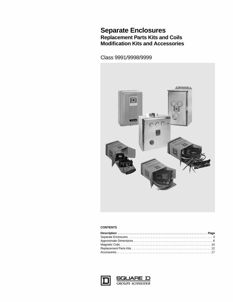
Separate enclosures can be used with open style devices for field assembly of enclosed controls. These enclosures, plus the open style components, will be equivalent to a factory-assembled device. Separate enclosures are to be used only with the equipment listed below:
•
NEMA Types 4 and 12
Class 9991 separate enclosures for Type S devices are supplied as standard with closing plates. See selection chart below for specific number of closing plates on various enclosures. For applications requiring enclosures without closing plates, consult Square D field office.
•
NEMA Type 3R
enclosures for field assembly of equipment for outdoor applications are provided with three closing plates, a reset mechanism and predrilled panel as standard. For conduit connection to the top of these enclosures, select watertight hubs from listing on Digest Page 3-9 in accordance with applicable code requirements. Square D’s NEMA Type 12 enclosures can also be modified for outdoor use. For details, refer to NEMA Type 12 enclosure modification information on Page 5.
NOTE: Not for use in high-corrosive outdoor locations and/or sea coast environments.
•
NEMA Type 4X
enclosures for Type S devices Sizes 0-2 and 30-60 Ampere, are provided as standard without closing plates. Cover-mounted control units for NEMA Type 4X separate enclosures are available as a factory modification only.
When closing plates are removed from NEMA Types 4, 12 & 3R enclosure covers, the openings can be used for easy installation of Class 9001 Type K or Type SK cover-mounted control units.
For Use With
Enclosure Classification
NEMASizeorAmpRating
NEMA Type 4XWatertight, Dust-tight and Corrosion-ResistantGlass-Polyester
NEMA Type 4
k
Watertight and DusttightStainless Steel
NEMA Type 12Dusttight and Driptight
NEMA Type 3RRainproof,SleetResistant,Outdoor Use
ClassTypes (All Pole Arrangements)
Type TypeNumber ofClosing Plates
TypeNumber of Closing Plates
Type
Manual Starters
2510 MBO, MCOMOM1M1P
MW1
q
MW11 .... MA1 .... ....
Magnetic Contactors
8502
a
SBO, SCO 0, 1 SCW20 SCW11 2 SCA11 2 SCH2
SDO 2 SDW20 SDW11 2 SDA11 2 SDH1
SEO 3 ... SEW11 3 SEA11 3 SEH1
SFO 4 ... SFW11 3 SFA11 3 SFH1
Magnetic Starters
8536
SBO, SCO 0, 1 SCW21 SCW11 2 SCA11 2 SCH2
SDO 2 SDW21 SDW11 2 SDA11 2 SDH1
SEO 3 ... SEW11
‡
3 SEA11
‡
3 SEH1
SFO 4 ... SFW11
‡
3 SFA11
‡
3 SFH1
Lighting Contactors Non-Combination Electrically- and Mechanically-held
8903
a
LO, LXO 20 Amp SDW20 SDW11 2 SDA11 2 SDH1
SMO 30 Amp SCW20
c
SCW11 2 SCA11 2 SCH2
SPO 60 Amp SCW20
c
SDW11 2 SDA11 2 SDH1
SQO 100 Amp ... SEW11
‡
3 SEA11
‡
3 SEH1
SVO 200 Amp ... ... ... ... ... SFH1
Reversing and Two-Speed Horizontally Arranged Contactors and Starters
8702
a
8736SBO, SCOSDO
0, 12
...SCW12SDW12
3SCA12SDA12
3......
8810 SBO & SCO 0, 1 ... SCW13 3 SCA13 3 ...
a
For contactors, replace reset assembly with proper closing plate; for NEMA Type 4 use Class 9001 Type K52, for NEMA Types 3R and 12 use Class 9001 Type K51. Class 9991 Types SCW20 and SDW20 are designed for contactors only, reset closing plates not required.
c
For electrically-held devices only.
u
Enclosure suitable for starter with melting alloy overload and solid state overload relays only.
k
The standard cabinet has a brushed finish. For electropolished finish, specify Form G16.
q
Type MBO, Size MO only.
Separate Enclosures
NEMA Type 3R, 4, 4x, and 12 – Class 9991
Type SCW21NEMA Type 4X
Enclosure
Type SCA11NEMA Type 12 Enclosure
Type SCW11NEMA Type 4
Enclosure
Type SCH2NEMA Type 3R Enclosure
© 1998 Square D All Rights Reserved
4
5/98
Flush Mounting Selection Table
Flush Mounting General Purpose
separate enclosures for Type S Sizes 0-2, 30-60 Ampere are provided with knock-outs in the cover for field assembly of one Class 9999 push button or selector switch kit and one Class 9999 pilot light kit. (Refer to Class 9999 for selection.) For Type S Size 3, 100 Ampere, three closing plates are provided for installation of Class 9001 Type K oiltight control units. For enclosure dimensions, refer to Page 6.
For Use With NEMASizeorAmpRating
Flush Mounting General Purpose (Components)
Flush PlatesMountingStrap
Pull Box
ClassTypes(All PoleArrangements)
StandardStainless Steel
k
Type Type
Type Type
2510 MBO & MCOMOM1M1P
MF1MF2
(with pullbox and plaster adjustment)(without pullbox but with mounting strap)
Magnetic Contactors
8502
a
SBO & SCO 0, 1 SCF11 SCF12 SCF2 SCF1
SDO 2 SDF11 SDF12 SDF2 SDF1
SEO 3 SEF11 (Enclosure Complete)
Magnetic Starters
8536SBO & SCO 0, 1 SCF11 SCF12 SCF2 SCF1
SDO 2 SDF11 SDF12 SDF2 SDF1
Lighting Contactors Non-Combination Electrically- and Mechanically-held
8903
a
LO, LXO 20 Amp SDF13 ... SDF2 SDF1
SMO 1-4 30 Amp SCF11 ... SCF2 SCF1
SMO 10-13 30 Amp SCF13 ... SCF2 SCF1
SPO 1-4 60 Amp SDF11 ... SDF2 SDF1
SPO 10-13 60 Amp SDF13 ... SDF2 SDF1
SQO 1-13 100 Amp SEF11 (Enclosure Complete)
a
For contactors, replace reset assembly with proper closing plate. For Flush Mounting use Class 9999 Type SG2 except for Class 9991 Type SDF11 which requires a Class 9001 Type K51 or K11 closing plate. Class 9991 Types SEF11 and LF1 are designed for contactors only, reset closing plates not required.
k
The standard cabinet has a brushed finish. For electropolished finish, specify Form G16.
Separate Enclosures
Class 9991 – NEMA Type 1 and Flush Mounting
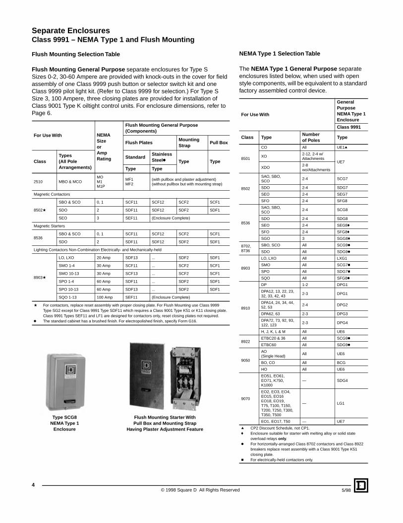
Flush Mounting Starter With Pull Box and Mounting Strap
Having Plaster Adjustment Feature
Type SCG8NEMA Type 1
Enclosure
NEMA Type 1 Selection Table
The
NEMA Type 1 General Purpose
separate enclosures listed below, when used with open style components, will be equivalent to a standard factory assembled control device.
For Use With
General PurposeNEMA Type 1Enclosure
Class 9991
Class TypeNumberof Poles
Type
8501
CO All UE1
q
XO2-12, 2-4 w/Attachments
UE7XDO
2-8wo/Attachments
8502
SAO, SBO,SCO
2-4 SCG7
SDO 2-4 SDG7
SEO 2-4 SEG7
SFO 2-4 SFG8
8536
SAO, SBO,SCO
2-4 SCG8
SDO 2-4 SDG8
SEO 2-4 SEG8
f
SFO 2-4 SFG8
f
SGO 3 SGG8
f
8702,8736
SBO, SCO All SCG9
k
SDO All SDG9
k
8903
LO, LXO All LXG1
SMO All SCG7
c
SPO All SDG7
c
SQO All SFG8
k
8910
DP 1-2 DPG1
DPA12, 13, 22, 23,32, 33, 42, 43
2-3 DPG1
DPA14, 24, 34, 44,52, 53
2-4 DPG2
DPA62, 63 2-3 DPG3
DPA72, 73, 92, 93,122, 123
2-3 DPG4
H, J, K, L & M All UE6
8922ETBC20 & 36 All SCG9
k
ETBC60 All SDG9
k
9050
AO(Single Head)
All UE6
BO, CO All BCG
HO All UE6
9070
EO51, EO61,EO71, K750,K1000
— SDG4
EO2, EO3, EO4,EO15, EO16EO18, EO19,T75, T100, T150,T200, T250, T300,T350, T500
— LG1
EO1, EO17, T50 — UE7
q
CP2 Discount Schedule, not CP1.
f
Enclosure suitable for starter with melting alloy or solid state overload relays
only
.
k
For horizontally-arranged Class 8702 contactors and Class 8922 breakers replace reset assembly with a Class 9001 Type K51 closing plate.
c
For electrically-held contactors only.
5
5/98 © 1998 Square D All Rights Reserved
Separate Enclosures
NEMA Types 1, 4, and Oversize – Class 9991
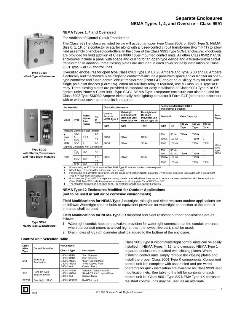
Type SCW4NEMA Type 4 Enclosure
Type SCG1with Starter, Transformerand Fuse Block Installed
Type SCA4NEMA Type 12 Enclosure
Class 9001 Type K oiltight/watertight control units can be easily installed in NEMA Types 4, 12, and oversized NEMA Type 1 separate enclosures provided with closing plates. When installing control units simply remove the closing plates and install the proper Class 9001 Type K components. Convenient control unit kits complete with assembled and pre-wired operators for quick installation are available as Class 9999 user modification kits. See table to the left for contents of each control unit kit. Class 9001 Type SK NEMA Type 4X corrosion resistant control units may be used as an alternate.
Control Unit Selection Table
Class 9999Type
Control FunctionKit Contents
Class & Type Description
SA3Start-StopPushbutton
1-9001 KR1B1-9001 KR1R1-9001 KN2011-9001 KN2022-9001 KA1
Start OperatorStop Operator“Start” Legend Plate“Stop” Legend PlateContact Block
SC8Hand-Off-AutoSelector Switch
1-9001 KS43B1-9001 KN2601-9001 KA1
Selector Operator Switch“Hand-Off-Auto” Legend PlateContact Block
SP28R Pilot Light (120 V) 1-9001 KP1R31 Red Pilot Light
NEMA Types 1, 4 and Oversized
For Addition of Control Circuit Transformer
The Class 9991 enclosures listed below will accept an open type Class 8502 or 8536, Type S, NEMA Size 0, 1, 1P, or 2 contactor or starter along with a fused-control circuit transformer (Form F4T) to allow field assembly of enclosed controllers. In the cover of the Class 9991 Type SCG1 enclosure, knock-outs are provided for field addition of Class 9999 cover-mounted control units. All other Class 8502 & 8536 enclosures include a panel with space and drilling for an open-type device and a fused-control circuit transformer. In addition, three closing plates are included in each cover for easy installation of Class 9001 Type K or SK control units.Oversized enclosures for open type Class 8903 Type L & LX 20 Ampere and Type S 30 and 60 Ampere electrically and mechanically held lighting contactors include a panel with space and drilling for an open- type contactor and fused-control circuit transformer (Form F4T) and/or an auxiliary relay for use with single pole pilot devices (Form R6). When an auxiliary relay is required, use a Class 8501 Type XO11 relay. Three closing plates are provided as standard for easy installation of Class 9001 Type K or SK control units. Note: A Class 9991 Type SCG1 NEMA Type 1 separate enclosure can also be used for Class 8903 Type SMO30 Ampere electrically-held lighting contactor if Form F4T (control transformer) with or without cover control units is required.
NEMA Type 12 Enclosures Modified for Outdoor Applications (not to be used in salt air or corrosive environments)
Field Modifications for NEMA Type 3
dusttight, raintight and sleet resistant outdoor applications are as follows: Watertight conduit hubs or equivalent provision for watertight connection at the conduit entrance shall be used.
Field Modifications for NEMA Type 3R
rainproof and sleet resistant outdoor applications are as follows:1. Watertight conduit hubs or equivalent provision for watertight connection at the conduit entrance,
when the conduit enters at a level higher than the lowest live part, shall be used.2. Drain holes of
1
/
8
inch diameter shall be added to the bottom of the enclosure.
For Use With Class 9991 Enclosure Recommended Class 9070
p
Transformer Selection
FuseBlock
Class Type
NEMASize orAmpRating
No.ofPoles
GeneralPurposeNEMA Type 1
Watertight and DusttightStainless Steel NEMA Type 4
k
Dusttight andDriptightIndustrial Use NEMA Type 12
u
Standard Extra Capacity
Type Type Type Type VA100 VA 150 VA 300 VAType Type Type
Magnetic Contactors and Starters
t
8502&8536
SBO&SCO
0 & 11-3
SCG1 SCW4 SCA4T50 50 VA T100
q
T150
q
...
Class9999TypeSFR4
4-5 T100
q
100 VA ... T150
q
...
SDO 2 2-5 SDG4 SDW4 SDA4 T100 100 VA ... T150 T300
Lighting Contactors Non-Combination
8903
LO,LXO
20A All
SDG3 SDW3 SDA3
T50 50 VA ... ... ...
T50 50 VA T100
q
T150
q
...
SMO 30A1-3 T100
q
100 VA ... T150
q
...
4-5T100 100 VA ... T150 T300
SPO 60A 2-5
q
For mounting in SCG1 enclosure a Class 9991 Type S1 adapter bracket is also required.
u
NEMA Type 12 modified for outdoor use (see below).
p
For price list and complete description, see the Class 9070 section. NOTE: Class 9991 Type SCG1 enclosure is provided with a Class 9999 Type SF4 fuse block as standard.
t
For contactors (Class 8502), a separate closing plate is provided with each enclosure to replace the reset mechanism with the exception of Class 9991 Type SCG1 which requires a separate reset closing plate Class 9999 Type SG2.
k
The standard cabinet has a brushed finish. For electropolished finish, specify Form G16.
arate Enclosures
ss 9991 – Approximate Dimensions
NEM
SepCla
A Type 1 – General Purpose Enclosures (Standard)
Class9991Type
For Use With Dimensions (inches/millimeters) (See Figure 1)Weight(Lbs)Class Type Size
No. ofPoles
Fig.No.
MountingScrews
A B C D E F G H I J K L
LXG1 8903 LO, LXO 20 Amp 2-12 1 ...7.81198
12.69322
6.03153
...1.0928
10.50267
1.0928
1.0928
5.63143
5.75146
1.0928
5.63143
8
SCG7
8903 SMO (E.H.) 30 Amp All
1 (3)#106.00152
10.00254
5.28134
3.0076
0.8822
8.13206
1.0025
0.9424
4.13105
5.00127
... ... 4
8502SAO 00 2-3
SBOSCO
01
All
SCG8 8536SAO 00 2-3
5.56141
SBOSCO
01
All
DPG2 8910 DP ... ...
SDG78903 SPO (E.H.) 60 Amp 2-12
1 (4)1/4"7.81198
12.69322
6.03153
...1.0928
10.50267
1.0928
1.0928
5.63143
5.75146
1.0928
5.63143
88502 SDO 2 All
SDG8 8536 SDO 2 All 6.31160DPG3 8910 DPA ... ...
SEG7 8502 SEO 3 All
1 (4)3/8"11.44286
21.81554
8.00203
...1.5339
18.75476
1.5339
1.5339
8.38213
7.75197
1.5339
8.38213
23SEG8 8536 SEO 3 All
DPG4 8910 DPA ... ...8.38213
SFG8
8502 SFO 4 All
2 (4)7/16"11.25286
25.15639
8.99228
8.60218
1.2532
1.2532
22.31567
1.4236
0.4411
... ... ... 348536 SFO 4 All
8903SQO(E.H. & M.H.)
100 Amp All
SCG98702j
SBO,SCO
0 & 1All 2 (4)5/16"
11.88302
11.88302
7.41188
9.75248
1.0627
1.0627
9.75248
1.0627
0.318
... ... ... 168922
ETBC20,ETBC36
...
SDG98702j SCO 2
All 2 (4)5/16"14.88378
14.13359
7.56192
12.75324
1.0627
1.0627
12.00305
1.0627
0.318
... ... ... 248922 ETBC60 ...
j Standard enclosure has space for a fused control transformer, Form F4T, on Sizes 0-2.
NEMA Type 1 – General Purpose Enclosures (Oversize)
Class9991Type
For Use With Dimensions (inches/millimeters) (See Figure 2)
Class Type SizeNo. ofPoles
Fig.No.
MountingScrews
A B C D E F G H IWeight(Lbs)
SDG3 8903
LO, LXOSMO (M.H.)SPO(Form F4T)
20 Amp30 Amp60 Amp
All
2 (4)5/16"14.88378
14.13359
7.56192
12.75324
1.0627
1.0627
12.00305
1.0627
0.318
15
SDG4
8502SDO(Form F4T)
2 All
218536
SDO(Form F4T)
2 All7.66194
9070EO51, EO61,EO71, T750,T1000
... ...7.56192
SCG1
8502SBO, SCO(Form F4T)
0, 1 All
3 (4)9/32"6.34161
15.88403
5.19132
4.66118
0.8421
14.38365
0.7519
0.287
9 SCG18536SBO, SCO(Form F4T)
0, 1 All
8903SMO (E.H.)(Form F4T)
30 Amp All
A
B
E D F
Reset
C
H
G
H
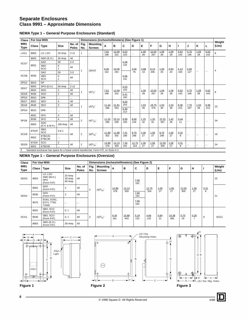
(4) I Dia.Mounting Holes
H
BG
CDA (4) I Dia. Mtg. Holes
E
Figure 3Figure 2Figure 1
AD
K L K
E
BF
H I H
G
RESET
CJ
PilotLight
© 1998 Square D All Rights Reserved6
5/98
Separate EnclosuresApproximate Dimensions– Class 9991
NEM
A Type 1 – General Purpose EnclosuresClass9991Type
For Use WithFigure
Dimensions (inches/millimeters) (see Figure 4)Weight(Lbs)Class Type
Numberof Poles
A B C D E F G H J L
UE1 8501 CO All
4
3.6392
5.28134
3.3184
1.8848
3.6392
1.0627
1.5038
1/4"t 1/2" - 3/4" 2
UE6
8910H, J, KL & M
All4.91125
5.75146
5.53140
3.5089
4.38111
1.5640
2.0051
9/32"1/2" - 3/4"1" - 11/4"
1/2" - 3/4" 29050
AO(Single Head)
All
HO All
UE78501
XO2-12, 2-4 w/Attachments
4.87125
7.79196
7.53191
3.5089
6.38162
1.3133
1.8848
#10 1/2" - 3/4" 4XDO 2-8
9070EO1, EO17T25, & T50
.......
LG1 9070
EO2, EO3, EO4, EO15, EO16, EO18, EO19, K75, K100, K150,K200, K250, K300, K350, & K500
.......7.53191
9.78248
5.91150
6.13155
8.38213
1.3133
1.8848
9/32" 1/2" - 3/4" - 1"q 10
BCG 9050 BO, CO All5.31135
9.31237
5.44138
2.5064
7.00178
1.8146
1.6943
5/16" 1/2" - 3/4" 81/2
t Class 9991 UE1 has only (3) -H diameter mounting holes; 2 in the bottom as shown and 1 centered at the top.q Class 9999 LG1 has three knockouts, top and bottom.
NEMA Type 3R – Rainproof and Sleet-Resistant Enclosures
Class9991Type
For Use With Dimensions (inches/millimeters) (see Figure 5)
Class Type SizeNo. ofPoles
A B C D1 D2 E F G1 G2 H1 H2 J K L M N PK.O.X
K.O.Y
SCH2
85028536
SBO,SCO
0, 1All
8.83224
12.30312
7.12181
1.3935
1.4437
6.00152
7.50191
2.6166
2.1956
2.0853
2.6266
14.28363
1.3735
1.3735
1.8848
4.38111
1.8346
1/23/41
1/23/418903 SMO
30Amp
SDH1
85028536
SDO 2
All9.83250
16.30414
6.62219
1.3935
1.4437
7.00178
11.50192
2.6166
2.1956
2.0853
2.6266
16.78426
1.3133
1.7544
2.1354
4.88124
1.8346
111/411/2
1/23/4
8903LOLXO
20Amp
8903 SPO60Amp
SEH1
85028536
SEO 3All
12.63326
25.30643
8.62219
1.3935
1.4437
10.00254
20.60521
2.6166
2.1956
2.0853
2.6266
19.78502
1.3133
2.3159
2.6968
6.38162
1.8346
111/4221/2
1/23/48903 SQO
100Amp
SFH1
85028536
SFO 4 All12.63326
40.301024
9.12232
1.3935
1.4437
10.00254
35.50902
2.6166
2.1956
2.0853
2.6266
20.28515
1.3133
2.3159
2.6968
6.38162
1.8346
111/4221/2
1/23/48903 SVO
200Amp
2-3
A
EB
D
C
G2
G
F
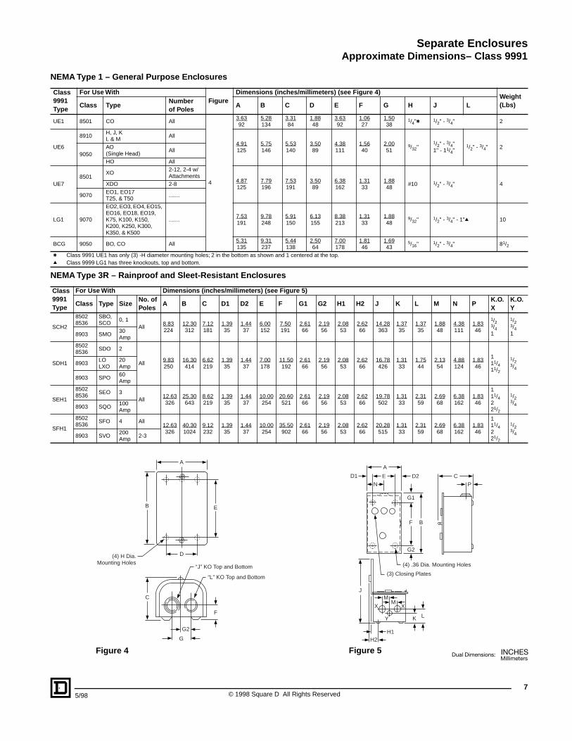
(4) H Dia.Mounting Holes
“J” KO Top and Bottom
“L” KO Top and Bottom
A
ED1 D2N
G1
G2
F B
C
P
J
LK
H1H2
MM
X X
Y
(4) .36 Dia. Mounting Holes
(3) Closing Plates
Figure 4 Figure 5
75/98 © 1998 Square D All Rights Reserved

arate Enclosuresss 9991 – Approximate Dimensions
NEM
SepCla
A Type 4X – Watertight and Corrosion Resistant Enclosures
Class9991Type
For Use With Dimensions (inches/millimeters) (see Figure 6) Hub Dia.
Weight(Lbs)Class Type
NEMASize orAmpRating
No. ofPoles
A B C D E F G H I J K LBot.OnlyW
Top &Bot.X
SCW208903
SMO(E.H.)
30A All
6.50165
6.44164
12.13308
0.7519
5.00127
8.25210
1.6943
3.3485
10.06
256
1.3133
2.1354
0.318
3/4” 1" 78502SBO,SCO
0, 1 All
SCW21 8536SBO,SCO
0, 1 All
SDW20
8903LO,LXO
20A All
8.50216
7.06179
13.88352
0.7519
7.00178
10.50
267
1.6943
3.9199
11.94
303
1.6341
2.3860
0.318
3/4” 11/2" 138903SPO(E.H.)
60A All
8502 SDO 2 AllSDW21 8536 SDO 2 All
NEMA Type 4 – Watertight Enclosures (Standard)
Class9991Type
For Use With Dimensions (inches/millimeters) (see Figure 6) Hub Dia.Weight(Lbs)Class Type Size
No. ofPoles
A B C D E F G H I J K LBot.OnlyW
Top &Bot.X
SCW11
8903 SMO 30 A All 6.38162
7.13181
13.19335
1.5640
3.2583
12.00305
0.5915
1.8848
11.78299
1.6341
2.3159
0.318 3/4" 1" 12
8502 SBO, SCO 0, 1 All
8536 SBO, SCO 0, 1 All6.38162
7.81198
13.19335
1.5640
3.2583
12.00305
0.5915
1.8848
11.78299
1.6341
2.3159
0.318
SDW11
8903 LO, LXO 20 A All8.13206
7.88200
16.19411
1.5640
5.00127
15.00381
1.0928
1.9449
14.75375
2.0051
2.6367
0.318 3/4" 11/2" 18
8903 SPO 60 A All8502 SDO 2 All
8536 SDO 2 All8.13206
8.56217
16.19411
1.5640
5.00127
15.00381
1.0928
2.8873
14.75375
2.0051
2.6367
0.318
SEW118903 SQO 100 A All 18.15
4618.77223
32.21818
3.0878
12.00305
30.50775
0.8622
3.6793
26.71678
2.5866
3.1981
0.4411
3/4" 21/2" 51
8502 SEO 3 All8536 SEO 3 All 18.15
4619.58243
32.21818
3.0878
12.00305
30.50775
0.8622
4.48114
26.71678
2.5866
3.1981
0.4411
SFW118536 SFO 4 All
8502 SFO 4 All18.15461
8.77223
32.21818
3.0878
12.00305
30.50775
0.8622
3.6793
26.71678
2.5866
3.1981
0.4411
NEMA Type 4 – Watertight Enclosures (Oversize)
Class9991Type
For Use With Dimensions (inches/millimeters) (see Figure 7) Hub Dia.Weight(Lbs)Class Type Size
No. ofPoles
A B C D E F G H I J K LBot.OnlyW
Top &Bot.X
SCW287028736
SCO 1 All
12.63321
7.81198
14.69373
2.5665
7.50191
13.50343
.5915
3.8898
18.41468
1.6642
2.3159
0.318
3/4" 1"
23
SCW3 8810SBOSCO
01
All 19
SCW485028536
SBO, SCO(Form F4T)
0, 1 All 24
SDW287028736
SDO 2 All
14.88378
7.25184
16.19411
2.5665
9.75248
15.00381
.3810
3.8898
20.88530
1.7244
2.6367
0.318
3/4" 11/2"
25
SDW3 8903LO, LXOSMO, SPO(Form F4T)
20 A30 A60 A
All 29
SDW485028536
SDO(Form F4T)
2 All 28
AD E D G
G
B
GF
IW X
J
HK
(4) L Mounting Holes
AD E D G
F C
J
KH
I
W X
B
G
(4) L Mounting Holes
Figure 6 Figure 7
© 1998 Square D All Rights Reserved8
5/98
5/98
Separate EnclosuresApproximate Dimensions– Class 9991
Figure 10
Figure 9
Figure 8
AD E D G
FC
G B
H
I
(4) J Dia. Mounting Holes
AD E D G
F C
B
I
H
G(4) J Dia. Mounting Holes
C
A
B
H E G
D F
H
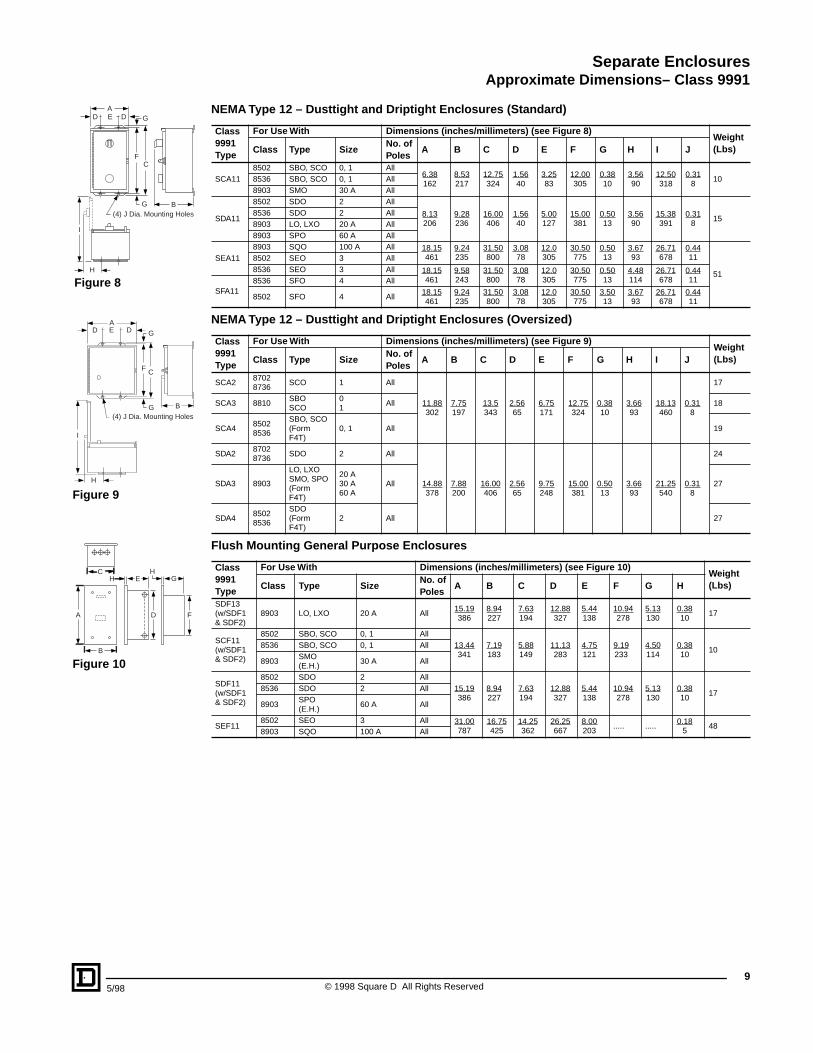
NEMA T
ype 12 – Dusttight and Driptight Enclosures (Standard)
Class9991Type
For Use With Dimensions (inches/millimeters) (see Figure 8)Weight(Lbs)Class Type Size
No. ofPoles
A B C D E F G H I J
SCA118502 SBO, SCO 0, 1 All
6.38162
8.53217
12.75324
1.5640
3.2583
12.00305
0.3810
3.5690
12.50318
0.318
108536 SBO, SCO 0, 1 All8903 SMO 30 A All
SDA11
8502 SDO 2 All
8.13206
9.28236
16.00406
1.5640
5.00127
15.00381
0.5013
3.5690
15.38391
0.318
158536 SDO 2 All8903 LO, LXO 20 A All8903 SPO 60 A All
SEA118903 SQO 100 A All 18.15
4619.24235
31.50800
3.0878
12.0305
30.50775
0.5013
3.6793
26.71678
0.4411
51
8502 SEO 3 All8536 SEO 3 All 18.15
4619.58243
31.50800
3.0878
12.0305
30.50775
0.5013
4.48114
26.71678
0.4411
SFA118536 SFO 4 All
8502 SFO 4 All18.15461
9.24235
31.50800
3.0878
12.0305
30.50775
3.5013
3.6793
26.71678
0.4411
NEMA Type 12 – Dusttight and Driptight Enclosures (Oversized)
Class9991Type
For Use With Dimensions (inches/millimeters) (see Figure 9)Weight(Lbs)Class Type Size
No. ofPoles
A B C D E F G H I J
SCA287028736
SCO 1 All
11.88302
7.75197
13.5343
2.5665
6.75171
12.75324
0.3810
3.6693
18.13460
0.318
17
SCA3 8810SBOSCO
01
All 18
SCA485028536
SBO, SCO(FormF4T)
0, 1 All 19
SDA287028736
SDO 2 All
14.88378
7.88200
16.00406
2.5665
9.75248
15.00381
0.5013
3.6693
21.25540
0.318
24
SDA3 8903
LO, LXOSMO, SPO(FormF4T)
20 A30 A60 A
All 27
SDA485028536
SDO(FormF4T)
2 All 27
Flush Mounting General Purpose Enclosures
Class9991Type
For Use With Dimensions (inches/millimeters) (see Figure 10)Weight(Lbs)Class Type Size
No. ofPoles
A B C D E F G H
SDF13(w/SDF1& SDF2)
8903 LO, LXO 20 A All15.19386
8.94227
7.63194
12.88327
5.44138
10.94278
5.13130
0.3810
17
SCF11(w/SDF1& SDF2)
8502 SBO, SCO 0, 1 All13.44341
7.19183
5.88149
11.13283
4.75121
9.19233
4.50114
0.3810
108536 SBO, SCO 0, 1 All
8903SMO(E.H.)
30 A All
SDF11(w/SDF1& SDF2)
8502 SDO 2 All15.19386
8.94227
7.63194
12.88327
5.44138
10.94278
5.13130
0.3810
178536 SDO 2 All
8903SPO(E.H.)
60 A All
SEF118502 SEO 3 All 31.00
78716.75425
14.25362
26.25667
8.00203
..... .....0.18
548
8903 SQO 100 A All
9© 1998 Square D All Rights Reserved
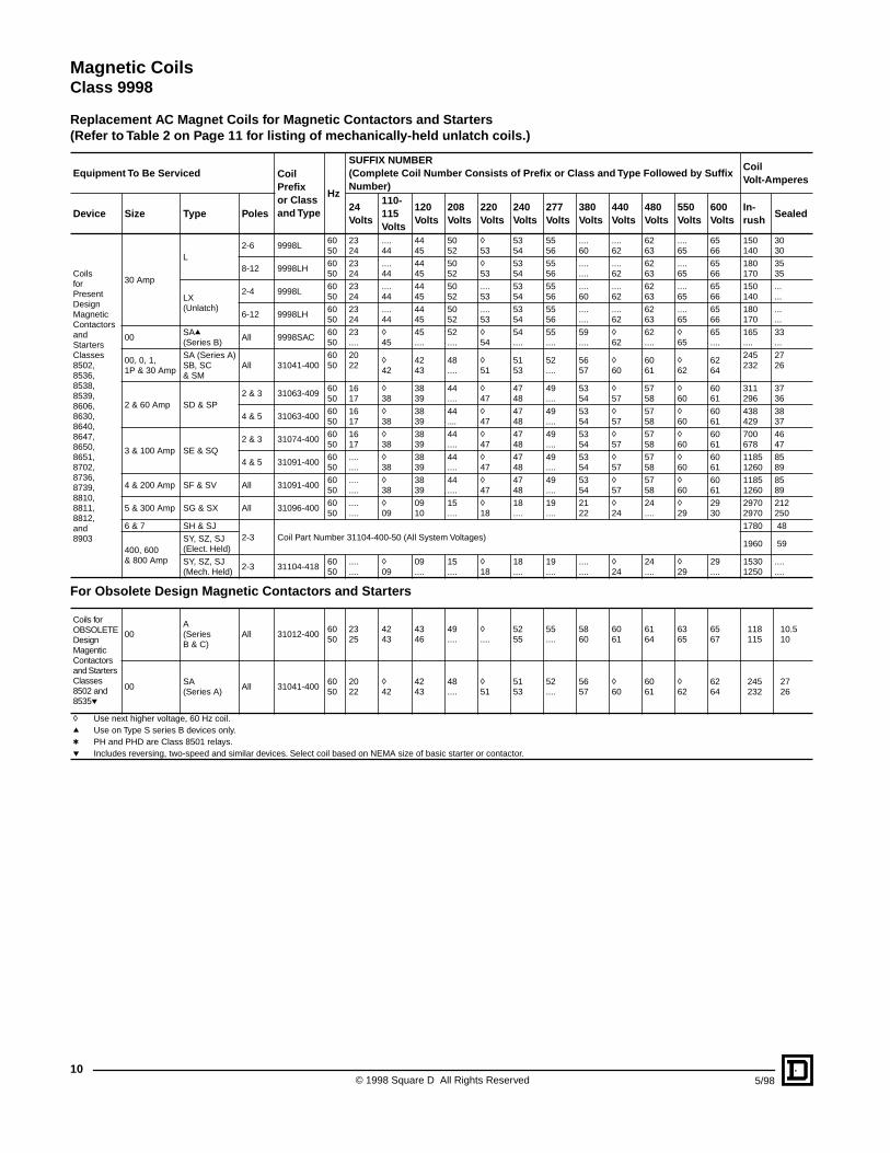
Magnetic CoilsClass 9998
Repl
acement AC Magnet Coils for Magnetic Contactors and Starters(Refer to Table 2 on Page 11 for listing of mechanically-held unlatch coils.)
Equipment To Be Serviced CoilPrefixor Classand Type
Hz
SUFFIX NUMBER(Complete Coil Number Consists of Prefix or Class and Type Followed by Suffix Number)
CoilVolt-Amperes
Device Size Type Poles24Volts
110-115Volts
120Volts
208Volts
220Volts
240Volts
277Volts
380Volts
440Volts
480Volts
550Volts
600Volts
In-rush
Sealed
CoilsforPresentDesignMagneticContactorsandStartersClasses8502,8536,8538,8539,8606,8630,8640,8647,8650,8651,8702,8736,8739,8810,8811,8812,and8903
30 Amp
L2-6 9998L
6050
2324
....44
4445
5052
h53
5354
5556
....60
....62
6263
....65
6566
150140
3030
8-12 9998LH6050
2324
....44
4445
5052
h53
5354
5556
....
........62
6263
....65
6566
180170
3535
LX(Unlatch)
2-4 9998L6050
2324
....44
4445
5052
....53
5354
5556
....60
....62
6263
....65
6566
150140
...
...
6-12 9998LH6050
2324
....44
4445
5052
....53
5354
5556
....
........62
6263
....65
6566
180170
...
...
00SAq(Series B)
All 9998SAC6050
23....
h45
45....
52....
h54
54....
55....
59....
h62
62....
h65
65....
165....
33...
00, 0, 1,1P & 30 Amp
SA (Series A)SB, SC& SM
All 31041-4006050
2022
h42
4243
48....
h51
5153
52....
5657
h60
6061
h62
6264
245232
2726
2 & 60 Amp SD & SP2 & 3 31063-409
6050
1617
h38
3839
44....
h47
4748
49....
5354
h57
5758
h60
6061
311296
3736
4 & 5 31063-4006050
1617
h38
3839
44....
h47
4748
49....
5354
h57
5758
h60
6061
438429
3837
3 & 100 Amp SE & SQ2 & 3 31074-400
6050
1617
h38
3839
44....
h47
4748
49....
5354
h57
5758
h60
6061
700678
4647
4 & 5 31091-4006050
....
....h38
3839
44....
h47
4748
49....
5354
h57
5758
h60
6061
11851260
8589
4 & 200 Amp SF & SV All 31091-4006050
....
....h38
3839
44....
h47
4748
49....
5354
h57
5758
h60
6061
11851260
8589
5 & 300 Amp SG & SX All 31096-4006050
....
....h09
0910
15....
h18
18....
19....
2122
h24
24....
h29
2930
29702970
212250
6 & 7 SH & SJ2-3 Coil Part Number 31104-400-50 (All System Voltages)
1780 48
400, 600& 800 Amp
SY, SZ, SJ(Elect. Held)
1960 59
SY, SZ, SJ(Mech. Held)
2-3 31104-4186050
....
....h09
09....
15....
h18
18....
19....
....
....h24
24....
h29
29....
15301250
....
....
For Obsolete Design Magnetic Contactors and Starters
Coils for OBSOLETE Design Magentic Contactors and Starters Classes 8502 and 8535p
00A(Series B & C)
All 31012-4006050
2325
4243
4346
49....
h....
5255
55....
5860
6061
6164
6365
6567
118115
10.510
00SA(Series A)
All 31041-4006050
2022
h42
4243
48....
h51
5153
52....
5657
h60
6061
h62
6264
245232
2726
h Use next higher voltage, 60 Hz coil.q Use on Type S series B devices only.t PH and PHD are Class 8501 relays.p Includes reversing, two-speed and similar devices. Select coil based on NEMA size of basic starter or contactor.
© 1998 Square D All Rights Reserved10
5/98
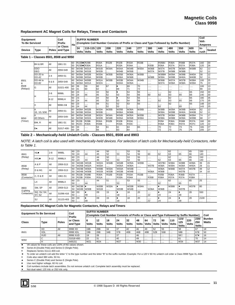
Magnetic CoilsClass 9998
11
Replacement AC Magnet Coils for Relays, Timers and Contactors
EquipmentTo Be Serviced
CoilPrefixor Classand Type
Hz
SUFFIX NUMBER(Complete Coil Number Consists of Prefix or Class and Type Followed by Suffix Number)
CoilVolt-Amperes
Device Type Poles24Volts
110-115Volts
120Volts
208Volts
220Volts
240Volts
277Volts
380Volts
440Volts
480Volts
550Volts
600Volts
In-rush
Sealed
Table 1 – Classes 8501, 8508 and 9050
8501&8508(Relays)
BH & BR All 1861-S16050
R22BkR23Bk
R29BR30A
R30AR31A
R32B.....
R32BR33A
R33AR34A
R33B.....
.....R35B
R35B‡R36A
R36AR37A
R36BR37A
R37AR38A
160120
3026
DDODEO
All 2959-S496050
W24BW25B
W31AW31B
W31BW32B
W34A.....
W34AW34B
W34BW35B
W35A.....
W36BW37A
W37AW37B
W37BW38B
W38AW38B
W38B...
6252
1211
DO-20 toDO-42
2-4 2959-S16050
W26AW26B
W32BW33A
W33AW33B
W35B.....
W35BW36A
W36AW36B
W36B.....
.....W38B
W38BuW39A
W39AW39B
W39BW40A
W40AW40B
5852
1211
DO-44 toDO-82
6 & 8 2959-S496050
W24AW26A
W30BW31A
W31AW32A
W33B.....
W33BW34A
W34AW35A
W34B.....
.....
.....W36BW37A
W37AW38A
W37BW38A
W38AW39A
10075
2522
G All 31021-4006050
3941
5960
6062
67.....
f69
6971
7072
.....
...............
.....
...............
.....
.....10090
1313
H2-8 9998L
6050
2324
.....44
4445
5052
f53
5354
5556
.....60
.....62
6263
.....65
6566
150140
3030
8-12 9998LH6050
2324
.....44
4445
5052
f53
5354
5556
.....
..........62
6263
.....65
6566
180170
3535
X All 9998-Xa6050
2324
.....44
44....
5152
5253
53....
55....
....
.........62
62.....
....65
65....
148143
2325
9050(Timer)
A1E, 1D, 5DE
All 2959-S1-6050
W26AW26B
W32BW33A
W33AW33B
W35B.....
W35BW36A
W36AW36B
W36B.....
.....
.....W38BW39A
W39AW39B
W39BW40A
W40AW40B
6252
1211
AAll Others
All 2959-S49-6050
W25AW25B
W31BW32A
W32AW32B
W34AW34B
W34BW35A
W35AW35B
W35BW36A
.....
.....W37BW38A
W38AW38B
W38BW39A
W39AW39B
7468
1717
Buu, R All 1861-S16050
R22BR22C
R29BR30A
R30AR30B
R32B.....
R32BR33A
R33AR33C
.....
...............
R35uR36A
R36AR36C
R36BR37A
R37AR37C
160120
3022
Bq All 31017-400-6050
3334
.....
.....5455
61.....
6163
6364
65.....
.....
.....7072
7273
7375
7576
165155
2727
Table 2 – Mechanically-held Unlatch Coils - Classes 8501, 8508 and 8903
NOTE: A latch coil is also used with mechanically-held devices. For selection of latch coils for Mechanically-held Contactors, refer to Table 1.
8501(Relay)
HLc 2-8 9998L6050
2324
.....44
4445
5052
.....53
5354
5556
.....60
.....62
6263
.....65
6566
150140
.....
.....
HXLc 8-12 9998LX6050
2324
.....44
4445
5052
.....53
5354
5556
.....
..........62
6263
.....65
6566
150140
.....
.....
8508(Relay)
A & P All 2959-S136050
W24BW25B
W31BW32A
W32AW33A
W34B.....
W34BW35A
W35AW36A
W35B.....
.....W37B
W37B‡W38A
W38AW39A
W38BW39A
W39AW40A
3928
1511
D & M1 All 2959-S136050
W23BW24B
W30AW30B
W30BW31B
W33AW33B
W33AW33B
W33BW34B
.....
..........W36A
W36AW36B
W36B.....
W37AW37B
W37B.....
3934
1210
8508(Contactor)
C, D & E All 1861-S16050
R22BR23B
R29BR30A
R30AR31A
R32B.....
R32BR33A
R33AR34A
R33B.....
.....R35B
R35BR36A
R36AR37A
R36BR37A
R37AR38A
. . .
. . .. . .. . .
8903(LightingContactors)
LX All 9998LX6050
23.....
.....44
44.....
51.....
.....53
53.....
55.....
.....
..........62
62.....
.....65
65.....
25. . .
. . .
. . .
SM, SP All 2959-S136050
W23BW24B
fW30B
W30BW31B
W33A.....
fW33B
W33BW34B
W34A.....
.....W36A
fW36B
W36B.....
fW37B
W37B.....
80. . .
. . .
. . .SQ, SV, SX,SY, SZ
All 31096-4166050
03.....
f09
09.....
15.....
f18
18.....
20.....
.....22
f24
24.....
f28
28. . .
550. . .
. . .
. . .
SJ All 31123-4036050
03.....
f09
09.....
15.....
f18
18.....
20.....
.....22
f24
24.....
f28
28.....
2100. . .
. . .
. . .
Replacement DC Magnet Coils for Magnetic Contactors, Relays and Timers
Equipment To Be Serviced CoilPrefixor Classand Type
SUFFIX NUMBER(Complete Coil Number Consists of Prefix or Class and Type Followed by Suffix Number) Coil
BurdenWattsClass Type Poles
6Volts
12Volts
18Volts
24Volts
32Volts
48Volts
64Volts
72Volts
90Volts
110Volts
115/125Volts
220Volts
230/250Volts
8501XD All 9998 XD 19B 28B 34 37 40 46 49 52 55 .... 58 .... 67 18XDL .... 9998 XDL 19B 28B 34B 37B 40B 46B 49B 52B 55B .... 58B .... 67B 50XUD All 9998 XUD 19 28 .... 37 .... 46 .... .... .... .... 58➀ .... 67p 16
9050C 31018-400- 22 31 .... 40 .... 49 .... .... .... .... 61 .... 70 14H 4491S1 W21 W24 .... W27 .... W30 .... .... .... .... W34 .... W37 14
k VA values for these coils are 120% of the values shown.uu Series B (Double Pole) and Series D (Single Pole).j Replaces Series 31111-400-coil.a To order an unlatch coil add the letter “L” to the type number and the letter “B” to the suffix number. Example: For a 120 V 60 Hz unlatch coil order a Class 9998 Type XL-44B.u Coils also rated 380 volts, 50 Hz.q Series C (Double Pole) and Series E (Single Pole).f Use next higher voltage, 60 Hz coil.c Coil numbers include latch assemblies. Do not remove unlatch coil. Complete latch assembly must be replaced.p Not dual rated. 125 Vdc or 250 Vdc only.
5/98 © 1998 Square D All Rights Reserved
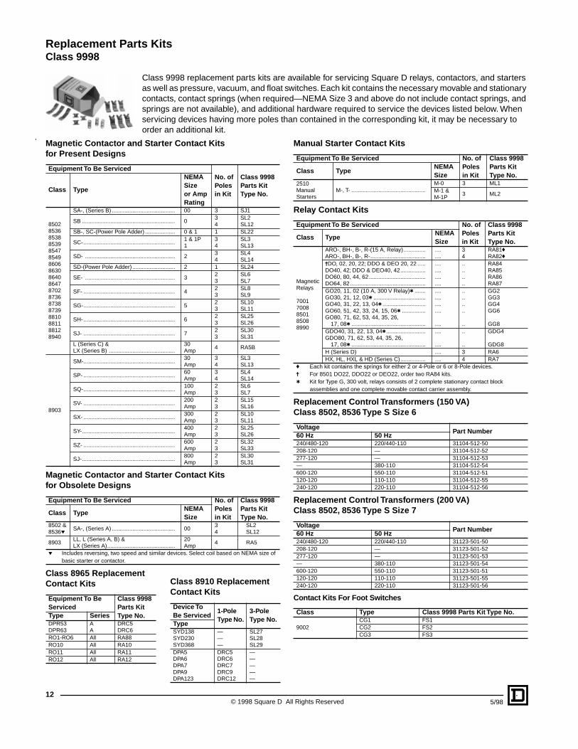
Class 9998 replacement parts kits are available for servicing Square D relays, contactors, and starters as well as pressure, vacuum, and float switches. Each kit contains the necessary movable and stationary contacts, contact springs (when required—NEMA Size 3 and above do not include contact springs, and springs are not available), and additional hardware required to service the devices listed below. When servicing devices having more poles than contained in the corresponding kit, it may be necessary to
Replacement Parts KitsClass 9998
Mf
.
12
order an additional kit.
agnetic Contactor and Starter Contact Kitsor Present Designs
Equipment To Be ServicedNo. ofPolesin Kit
Class 9998Parts KitType No.
Class Type
NEMASizeor AmpRating
850285368538853985478549860686308640864787028736873887398810881188128940
SA-, (Series B) ........................................ 00 3 SJ1
SB ........................................................... 034
SL2SL12
SB-, SC-(Power Pole Adder) ................... 0 & 1 1 SL22
SC-.......................................................... 1 & 1P1
34
SL3SL13
SD- ......................................................... 234
SL4SL14
SD-(Power Pole Adder) ........................... 2 1 SL24
SE- ......................................................... 323
SL6SL7
SF- .......................................................... 423
SL8SL9
SG-.......................................................... 523
SL10SL11
SH-.......................................................... 623
SL25SL26
SJ- .......................................................... 723
SL30SL31
L (Series C) &LX (Series B) ..........................................
30Amp
4 RA5B
8903
SM-.......................................................... 30Amp
34
SL3SL13
SP- .......................................................... 60Amp
34
SL4SL14
SQ-.......................................................... 100Amp
23
SL6SL7
SV- .......................................................... 200Amp
23
SL15SL16
SX- .......................................................... 300Amp
23
SL10SL11
SY-........................................................... 400Amp
23
SL25SL26
SZ- .......................................................... 600Amp
23
SL32SL33
SJ-........................................................... 800Amp
23
SL30SL31
Magnetic Contactor and Starter Contact Kitsfor Obsolete Designs
Equipment To Be Serviced No. ofPolesin Kit
Class 9998Parts KitType No.
Class TypeNEMASize
8502 &8536p
SA-, (Series A) ........................................ 0034
SL2SL12
8903LL, L (Series A, B) &LX (Series A)...........................................
20Amp
4 RA5
p Includes reversing, two speed and similar devices. Select coil based on NEMA size of basic starter or contactor.
Class 8965 ReplacementContact Kits
Equipment To Be Serviced
Class 9998Parts KitType No.Type Series
DPR53DPR63
AA
DRC5DRC6
RO1-RO6 All RA88RO10 All RA10RO11 All RA11RO12 All RA12
Manual Starter Contact Kits
Equipment To Be Serviced No. ofPolesin Kit
Class 9998Parts KitType No.
Class TypeNEMASize
2510ManualStarters
M-, T- ............................................... M-0 3 ML1M-1 &M-1P
3 ML2
Relay Contact Kits
Equipment To Be Serviced No. ofPolesin Kit
Class 9998Parts KitType No.
Class TypeNEMASize
MagneticRelays
70017008850185088990
ARO-, BH-, B-, R-(15 A, Relay).............. ARO-, BH-, B-, R-...................................
....
....34
RA81fRA82f
jDO, 02, 20, 22; DDO & DEO 20, 22 .....DO40, 42; DDO & DEO40, 42................DO60, 80, 44, 62....................................DO64, 82................................................
....
....
....
....
..
..
..
..
RA84RA85RA86RA87
GO20, 11, 02 (10 A, 300 V Relay)t .......GO30, 21, 12, 03t .................................GO40, 31, 22, 13, 04t ...........................GO60, 51, 42, 33, 24, 15, 06t ...............GO80, 71, 62, 53, 44, 35, 26,
17, 08t ...............................................
....
....
....
....
....
..
..
..
..
..
GG2GG3GG4GG6
GG8GDO40, 31, 22, 13, 04t .........................GDO80, 71, 62, 53, 44, 35, 26,
17, 08t ...............................................
....
....
..
..
GDG4
GDG8H (Series D) .... 3 RA6HX, HL, HXL & HD (Series C)................ .... 4 RA7
f Each kit contains the springs for either 2 or 4-Pole or 6 or 8-Pole devices.j For 8501 DO22, DDO22 or DEO22, order two RA84 kits.t Kit for Type G, 300 volt, relays consists of 2 complete stationary contact block
assemblies and one complete movable contact carrier assembly.
Replacement Control Transformers (150 VA)Class 8502, 8536 Type S Size 6
VoltagePart Number
60 Hz 50 Hz240/480-120 220/440-110 31104-512-50208-120 — 31104-512-52277-120 — 31104-512-53— 380-110 31104-512-54600-120 550-110 31104-512-51120-120 110-110 31104-512-55240-120 220-110 31104-512-56
Replacement Control Transformers (200 VA)Class 8502, 8536 Type S Size 7
VoltagePart Number
60 Hz 50 Hz240/480-120 220/440-110 31123-501-50208-120 — 31123-501-52277-120 — 31123-501-53— 380-110 31123-501-54600-120 550-110 31123-501-51120-120 110-110 31123-501-55240-120 220-110 31123-501-56
Contact Kits For Foot Switches
Class Type Class 9998 Parts Kit Type No.
9002CG1 FS1CG2 FS2CG3 FS3
Class 8910 ReplacementContact Kits
Device To Be Serviced
1-PoleType No.
3-PoleType No.
TypeSYD138SYD230SYD368
———
SL27SL28SL29
DPA5DPA6DPA7DPA9DPA123
DRC5DRC6DRC7DRC9DRC12
—————
© 1998 Square D All Rights Reserved 5/98

135/98 © 1998 Square D All Rights Reserved
Replacement Parts KitsStarter Accessories – Class 9998
Contact Units for Melting Alloy Type Overload Relays
One normally-closed contact, Class 9998 Type SO1, is provided in each overload relay block on Type S starters Sizes 00-4 and Size 6. On the Type S Size 5, a normally-closed contact is provided with each of the three overload relay blocks. The Class 9998 Type SO1 contact unit listed below is provided as standard in each Class 9065 Type M melting alloy overload relay. Contact modules can be easily replaced and are identified in the table below. Isolated overload relay alarm circuit contacts are available as an optional feature. A pilot light or alarm bell can be wired in series with this contact to indicate that the overload relay has tripped. For further information on isolated alarm contacts, refer to Class 9999 Types SO4 and SO5.
Class 9998 Type UB Universal Baseplate
A universal baseplate may be used to retrofit a Square D Type “S” NEMA starter into an application which is currently using a competitive NEMA starter. The universal baseplate is a metal plate which attaches to the panel in the location of the starter to be replaced. The Type “S” starter then mounts to the baseplate. It is available for NEMA Sizes 00 through 4, and mounting screws are provided with each plate.
The universal baseplate adapter allows the Type “S” starter to replace the following competitive starters:
Melting Alloy Overload Relay Jumper Strap Kits
Jumper strap kits are for use on three-phase manual or magnetic starters with melting alloy overload relays only, where a three-phase starter is used to control a single-phase motor. These kits will include two jumper straps, a wiring diagram showing how to wire a three-phase starter to control a single-phase motor, and single-phase (one thermal unit) selection tables.
Magnetic StarterDescription
Parts KitNumber
NEMASize
Type Series
00-4& 6
SA-SFSH
A & B Standard N.C. contact unit . . . . . . . . . . . . . . . . . . . . . . . . . . .Class 9998Type SO1u
5 SG AStandard N.C. contact unit . . . . . . . . . . . . . . . . . . . . . . . . . . . 31102-514-50N.C. and N.O. alarm (three
point) contact unit . . . . . . . . . . . . . . . . . . . . . . . . . . . . . . . .31102-514-51
u The Type SO1 is also the replacement contact unit for Class 9065 Type M melting alloy overload relays.
Competitor StarterType UB01 Type UB02 Type UB03 Type UB04NEMA Size
Allen Bradley 509 0, 1 2 3 4Allen Bradley 709 1 2 3 4Cutler Hammer Freedom Series 00, 0, 1 2 3 4Furnas ESP100 0, 1 2 3 4Furnas INNOVA 0, 1 2 3 4General Electric CR306 00, 0, 1 2 3 4
ClassFor Starter Class 9998
Kit Type NumberSize Type
ALL00, 0, 1, 2 and M0 & M1 SA, SB, SC, SD and M & T (Manual) SO313,4 SE, SF SO325 SG None Available
Class 9998 Type SO1
Overload Contact Unit Part No. 31102-514-50
Melting Alloy Overload Relay Jumper Strap Kits
L1 L2
1 L1 L2 L3
T1
T1
T2
T2
T3
MotorThree Phase StarterWired to Control aSingle Phase Motor
Disconnecting Means, Providedby User, or with Controller
© 1998 Square D All Rights Reserved14
5/98
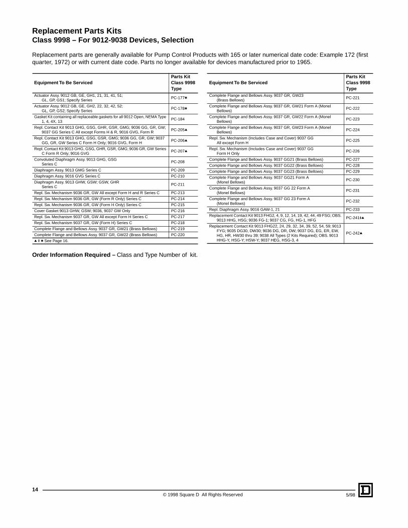
Replacement parts are generally available for Pump Control Products with 165 or later numerical date code: Example 172 (first quarter, 1972) or with current date code. Parts no longer available for devices manufactured prior to 1965.
Order Information Required – Class and Type Number of kit.
Equipment To Be ServicedParts KitClass 9998Type
Actuator Assy. 9012 GB, GE, GH1, 21, 31, 41, 51; GL, GP, GS1; Specify Series
PC-177t
Actuator Assy. 9012 GB, GE, GH2, 22, 32, 42, 52; GL, GP, GS2; Specify Series
PC-178t
Gasket Kit containing all replaceable gaskets for all 9012 Open, NEMA Type 1, 4, 4X, 13
PC-184
Repl. Contact Kit 9013 GHG, GSG, GHR, GSR, GMG; 9036 GG, GR, GW; 9037 GG Series C All except Forms H & R, 9016 GVG, Form R
PC-205q
Repl. Contact Kit 9013 GHG, GSG, GSR, GMG; 9036 GG, GR, GW; 9037 GG, GR, GW Series C Form H Only; 9016 GVG, Form H
PC-206q
Repl. Contact Kit 9013 GHG, GSG, GHR, GSR, GMG; 9036 GR, GW Series C Form R Only; 9016 GVG
PC-207q
Convoluted Diaphragm Assy. 9013 GHG, GSG Series C
PC-208
Diaphragm Assy. 9013 GMG Series C PC-209
Diaphragm Assy. 9016 GVG Series C PC-210
Diaphragm Assy. 9013 GHW, GSW; GSW, GHR Series C
PC-211
Repl. Sw. Mechanism 9036 GR, GW All except Form H and R Series C PC-213
Repl. Sw. Mechanism 9036 GR, GW (Form R Only) Series C PC-214
Repl. Sw. Mechanism 9036 GR, GW (Form H Only) Series C PC-215
Cover Gasket 9013 GHW, GSW; 9036, 9037 GW Only PC-216
Repl. Sw. Mechanism 9037 GR, GW All except Form H Series C PC-217
Repl. Sw. Mechanism 9037 GR, GW (Form H) Series C PC-218
Complete Flange and Bellows Assy. 9037 GR, GW21 (Brass Bellows) PC-219
Complete Flange and Bellows Assy. 9037 GR, GW22 (Brass Bellows) PC-220
q u t See Page 16.
Equipment To Be ServicedParts KitClass 9998Type
Complete Flange and Bellows Assy. 9037 GR, GW23 (Brass Bellows)
PC-221
Complete Flange and Bellows Assy. 9037 GR, GW21 Form A (Monel Bellows)
PC-222
Complete Flange and Bellows Assy. 9037 GR, GW22 Form A (Monel Bellows)
PC-223
Complete Flange and Bellows Assy. 9037 GR, GW23 Form A (Monel Bellows)
PC-224
Repl. Sw. Mechanism (Includes Case and Cover) 9037 GG All except Form H
PC-225
Repl. Sw. Mechanism (Includes Case and Cover) 9037 GG Form H Only
PC-226
Complete Flange and Bellows Assy. 9037 GG21 (Brass Bellows) PC-227
Complete Flange and Bellows Assy. 9037 GG22 (Brass Bellows) PC-228
Complete Flange and Bellows Assy. 9037 GG23 (Brass Bellows) PC-229
Complete Flange and Bellows Assy. 9037 GG21 Form A (Monel Bellows)
PC-230
Complete Flange and Bellows Assy. 9037 GG 22 Form A (Monel Bellows)
PC-231
Complete Flange and Bellows Assy. 9037 GG 23 Form A (Monel Bellows)
PC-232
Repl. Diaphragm Assy. 9016 GAW-1, 21 PC-233
Replacement Contact Kit 9013 FHG2, 4, 9, 12, 14, 19, 42, 44, 49 FSG; OBS. 9013 HHG, HSG; 9036 FG-1; 9037 CG, FG, HG-1, HFG
PC-241uq
Replacement Contact Kit 9013 FHG22, 24, 29, 32, 34, 39, 52, 54, 59; 9013 FYG; 9035 DG30, DW30; 9036 DG, DR, DW; 9037 DG, EG, ER, EW, HG, HR, HW30 thru 39; 9038 All Types (2 Kits Required); OBS. 9013 HHG-Y, HSG-Y; HSW-Y; 9037 HEG, HSG-3, 4
PC-242q
Replacement Parts KitsClass 9998 – For 9012-9038 Devices, Selection
Replacement Parts KitsFor 9012-9038 Devices, Selection – Class 9998
15
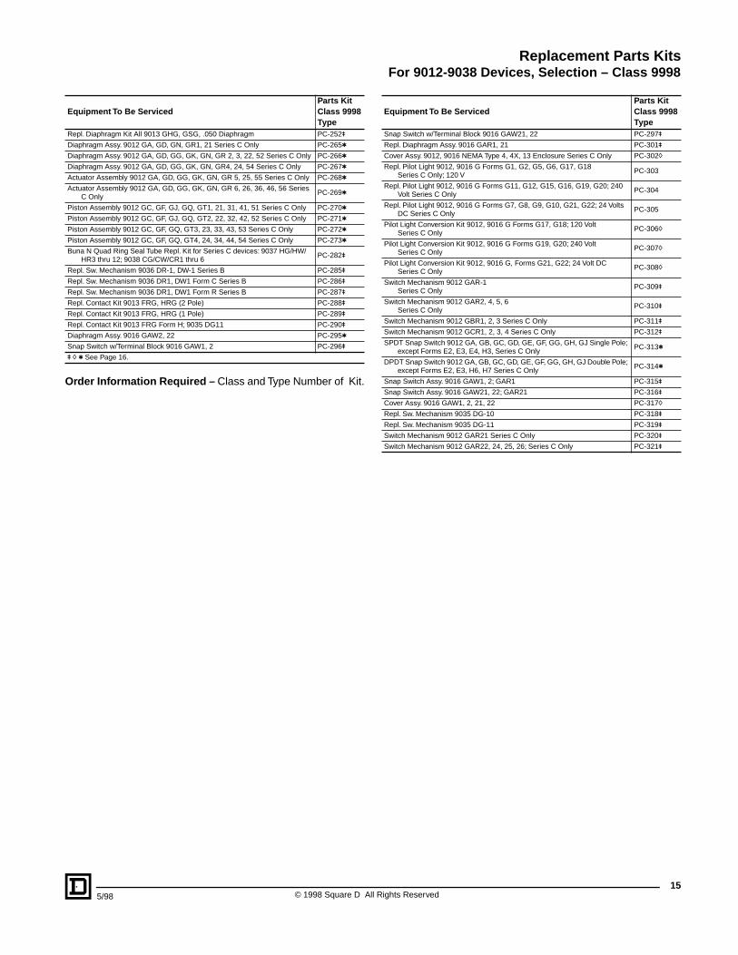
Order Information Required – Class and Type Number of Kit.
Equipment To Be ServicedParts KitClass 9998Type
Repl. Diaphragm Kit All 9013 GHG, GSG, .050 Diaphragm PC-252u
Diaphragm Assy. 9012 GA, GD, GN, GR1, 21 Series C Only PC-265t
Diaphragm Assy. 9012 GA, GD, GG, GK, GN, GR 2, 3, 22, 52 Series C Only PC-266t
Diaphragm Assy. 9012 GA, GD, GG, GK, GN, GR4, 24, 54 Series C Only PC-267t
Actuator Assembly 9012 GA, GD, GG, GK, GN, GR 5, 25, 55 Series C Only PC-268t
Actuator Assembly 9012 GA, GD, GG, GK, GN, GR 6, 26, 36, 46, 56 Series C Only
PC-269t
Piston Assembly 9012 GC, GF, GJ, GQ, GT1, 21, 31, 41, 51 Series C Only PC-270t
Piston Assembly 9012 GC, GF, GJ, GQ, GT2, 22, 32, 42, 52 Series C Only PC-271t
Piston Assembly 9012 GC, GF, GQ, GT3, 23, 33, 43, 53 Series C Only PC-272t
Piston Assembly 9012 GC, GF, GQ, GT4, 24, 34, 44, 54 Series C Only PC-273t
Buna N Quad Ring Seal Tube Repl. Kit for Series C devices: 9037 HG/HW/HR3 thru 12; 9038 CG/CW/CR1 thru 6
PC-282u
Repl. Sw. Mechanism 9036 DR-1, DW-1 Series B PC-285u
Repl. Sw. Mechanism 9036 DR1, DW1 Form C Series B PC-286u
Repl. Sw. Mechanism 9036 DR1, DW1 Form R Series B PC-287u
Repl. Contact Kit 9013 FRG, HRG (2 Pole) PC-288u
Repl. Contact Kit 9013 FRG, HRG (1 Pole) PC-289u
Repl. Contact Kit 9013 FRG Form H; 9035 DG11 PC-290u
Diaphragm Assy. 9016 GAW2, 22 PC-295t
Snap Switch w/Terminal Block 9016 GAW1, 2 PC-296u
u h t See Page 16.
Equipment To Be ServicedParts KitClass 9998Type
Snap Switch w/Terminal Block 9016 GAW21, 22 PC-297u
Repl. Diaphragm Assy. 9016 GAR1, 21 PC-301u
Cover Assy. 9012, 9016 NEMA Type 4, 4X, 13 Enclosure Series C Only PC-302h
Repl. Pilot Light 9012, 9016 G Forms G1, G2, G5, G6, G17, G18 Series C Only; 120 V
PC-303
Repl. Pilot Light 9012, 9016 G Forms G11, G12, G15, G16, G19, G20; 240 Volt Series C Only
PC-304
Repl. Pilot Light 9012, 9016 G Forms G7, G8, G9, G10, G21, G22; 24 Volts DC Series C Only
PC-305
Pilot Light Conversion Kit 9012, 9016 G Forms G17, G18; 120 Volt Series C Only
PC-306h
Pilot Light Conversion Kit 9012, 9016 G Forms G19, G20; 240 Volt Series C Only
PC-307h
Pilot Light Conversion Kit 9012, 9016 G, Forms G21, G22; 24 Volt DC Series C Only
PC-308h
Switch Mechanism 9012 GAR-1Series C Only
PC-309u
Switch Mechanism 9012 GAR2, 4, 5, 6Series C Only
PC-310u
Switch Mechanism 9012 GBR1, 2, 3 Series C Only PC-311u
Switch Mechanism 9012 GCR1, 2, 3, 4 Series C Only PC-312u
SPDT Snap Switch 9012 GA, GB, GC, GD, GE, GF, GG, GH, GJ Single Pole; except Forms E2, E3, E4, H3, Series C Only
PC-313t
DPDT Snap Switch 9012 GA, GB, GC, GD, GE, GF, GG, GH, GJ Double Pole; except Forms E2, E3, H6, H7 Series C Only
PC-314t
Snap Switch Assy. 9016 GAW1, 2; GAR1 PC-315u
Snap Switch Assy. 9016 GAW21, 22; GAR21 PC-316u
Cover Assy. 9016 GAW1, 2, 21, 22 PC-317h
Repl. Sw. Mechanism 9035 DG-10 PC-318u
Repl. Sw. Mechanism 9035 DG-11 PC-319u
Switch Mechanism 9012 GAR21 Series C Only PC-320u
Switch Mechanism 9012 GAR22, 24, 25, 26; Series C Only PC-321u
5/98 © 1998 Square D All Rights Reserved

Replacement Parts KitsClass 9998 – For 9012-9038 Devices, Selection
E
quipment To Be ServicedParts KitClass 9998Type
Switch Mechanism 9012 GBR21, 22, 23; Series C Only PC-322
Switch Mechanism 9012 GCR21, 22, 23, 24; Series C Only PC-323
Switch Mechanism 9012 GDR1; Series C Only PC-324
Switch Mechanism 9012 GDR2, 4, 5, 6; Series C Only PC-325
Switch Mechanism 9012 GER1, 2, 3; Series C Only PC-326
Switch Mechanism 9012 GFR1, 2, 3, 4; Series C Only PC-327
Switch Mechanism 9012 GDR21; Series C Only PC-328
Switch Mechanism 9012 GDR22, 24, 25, 26; Series C Only PC-329
q Contacts are 2-Pole; diaphragm fits Pressure Switch only.u These kits also contain replacement diaphragm for pressure switch.h Give complete CLASS, TYPE, FORM information to be stamped on replacement cover.t If one of these Form designations appears on the pressure switch nameplate, the 9998
PC number must be COMPLETED with that same FORM suffix from the tables below and the Form price added to the kit price.
Equipment To Be ServicedParts KitClass 9998Type
Switch Mechanism 9012 GER21, 22, 23; Series C Only PC-330
Switch Mechanism 9012 GFR21, 22, 23, 24; Series C”Only PC-331
Fluorocarbon Polymer such as VITON® Quad Ring Seal Tube Repl. Kit for Series C devices: 9037 HG/HW/HR3 thru 12; 9038 CG/CW/CR1 thru 6
PC-333
Repl. Sw. Mechanism 9035 DR10, DW10, DR30, DW30 PC-334
Repl. Sw. Mechanism 9035 DR11, DW11, DR31, DW31 PC-335
Repl. Nitrile Rubber such as Buna N Seal Kit for Series A devices: 9037 HG/HW/HR30 thru 39; 9038 CG/CW/CR31 thru 36
PC-337
Repl. Fluorocarbon Polymer such as VITON Seal Kit for Series A devices with Form Z19 or Z20: 9037 HG/HW/HR30 thru 39; 9038 CG/CW/CR31 thru 36
PC-338
Repl. Fluorocarbon Polymer such as VITON Seal Kit for Series C 9038D and 9038J
PC-341
9013F Plastic Flange (1⁄4" NPTF) 6 long screws, diaphragm and warning label
PC-342
© 1998 Square D All Rights Reserved16
5/98
Order Information Required – Class and Type Number of kit.
Factory Order Modifications for Kits Used on Class 9012 - 9013 Devices.
Form Applies To:E2 PC313, 314
H3 PC313
01PC177 thru 179PC265 thru 269
Q1PC177 thru 179PC268, 269
PC265 thru 267
Q3PC177 thru 178PC268, 269
PC266, 267
Form Applies To:
Q4PC177 thru 178PC268, 269
PC265 thru 267
Q5 PC270 thru 273
Q13PC177 thru 179PC266 thru 269
Q14PC177 thru 179PC266 thru 269
PC265, 295
Z PC265 thru 269
Z16 PC265 thru 269
Z18PC177, 178PC265 thru 273
175/98 © 1998 Square D All Rights Reserved
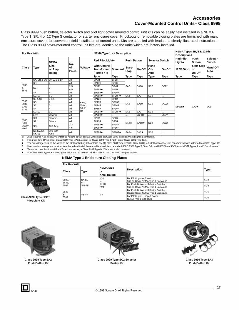
AccessoriesCover-Mounted Control Units– Class 9999
Class 9999 push button, selector switch and pilot light cover mounted control unit kits can be easily field installed in a NEMA Type 1, 3R, 4 or 12 Type S contactor or starter enclosure cover. Knockouts or removable closing plates are furnished with many enclosure covers for convenient field installation of control units. Kits are supplied with leads and clearly illustrated instructions. The Class 9999 cover-mounted control unit kits are identical to the units which are factory installed.
For Use With NEMA Type 1 Kit DescriptionNEMA Types 3R, 4 & 12 Kit Descriptionh
Class Type
NEMASizeor AmpRating
No.ofPoles
Voltage
Red Pilot Lightq Push Button Selector SwitchRed Pilot Lightq
Push Button
Selector Switch
With ControlTransformer(Form F4T)
StandardStart-Stop
On-OffHand-Off-Auto
On-Off 120V 60 HzStart-StoporOn-Off
Hand-Off-Auto
Type Type Type Type Type Type Type Type Type
8502&8536
SA, SB & SC 00, 0, 1 & 1P All
6-600Volts50-60Hz
SP2R SP2R
SA2 SA10 SC2 SC22
SP28Rk SA3a SC8
SD 2 All SP13R SP3R
SE 32-3 SP4R SP4R4-5 SP28Rk SP5R
SF 4 All SP28Rk SP15RSG-SJ 5-7 All SP28Rk SP28Rk SA3 SA3 SC8 ....
8538853987028736
SB & SC 0 & 1 All SP12R SP12R
SA2 SA10 SC2 SC22SD 2 All SP13R SP13RSE 3 All SP14R SP14RSF 4 All SP15R SP15RSG-SJ 5-7 All SP28Rk SP28Rk SA3 SA3 SC8 ....
8903(Elec-tricallyHeld)
LXt 20 Amp All SP28Rk – .... LXPBp .... LXSpSM 30 Amp All SP2R SP2R
SA2a SA10a SC2 SC22SP 60 Amp All SP13R SP3R
SQ 100 Amp2-3 SP28Rk SP14R4-5 SP28Rk SP15R
SJ, SV, SXSY, SZ
200-800Amp
All SP28Rk SP28Rk SA3a SA3a SC8 ....
a Also requires N.O. auxiliary contact for holding circuit contact when used on Class 8903 electrically held lighting contactors.q For green lens ONLY order Class 9999 Type SPG1, except for Class 9999 Type SP28R order Class 9001 Type G31.k The coil voltage must be the same as the pilot light rating. Kit contains one (1) Class 9001 Type KP1R31120V, 60 Hz red pilot light control unit. For other voltages, refer to Class 9001 Type KP.h User made openings are required in order to field install these modification kits on standard 8502, 8536 Type S Sizes 0-2, and 8903 Sizes 30-60 Amp NEMA Types 4 and 12 enclosures.p To mount control unit in a NEMA Type 1 enclosure, a Class 9999 Type BLX bracket is also required.t For Class 8903 Type LX NEMA Types 3R, 4 and 12 control unit kits, refer to the Class 8903 Digest section.
NEMA Type 1 Enclosure Closing Plates
For Use With
Description TypeClass Type
NEMA SizeorAmp. Rating
8502,8536,8903
SA-SEorSM-SP
00-3or30-60Amp
For Pilot Light or Reset -Slip-on Cover NEMA Type 1 Enclosure
SG2
For Push Button or Selector Switch -Slip-on Cover NEMA Type 1 Enclosure
SG3
8538&8539
SB-SF 0-4
For Push Button or Selector Switch -Hinged Cover NEMA Type 1 Enclosure
SG1
For Pilot Light - Hinged CoverNEMA Type 1 Enclosure
SG2Class 9999 Type SP2R Pilot Light Kit
Class 9999 Type SA2Push Button Kit
Class 9999 Type SC2 Selector Switch Kit
Class 9999 Type SA3 Push Button Kit

© 1998 Square D All Rights Reserved18
5/98
AccessoriesClass 9999 – Auxiliary Contacts
Auxiliary Contacts for Manual and Magnetic Contactors and Starters
Internal Contacts
Class 9999 Type SX11 internal contact kit is a replacement unit for the N.O. holding circuit contact supplied as standard on Type S Sizes 00-2 three-phase starters and contactors. The Class 9999 Type X12 is a replacement unit for the N.C. electrical contact which is furnished as standard on Type S, Sizes 00-2 mechanically-interlocked devices (e.g. Class 8736 reversing starters). Internal contacts are also used on Class 2510 Types M & T manual starters. The internal contacts can be used for other applications as long as the electrical rating is not exceeded. See table below for electrical ratings.
External Contacts
Class 9999 Type SX6 external auxiliary contact is supplied as standard for the N.O. holding circuit contact on Type S Sizes 3-7 starters and contactors. Additional auxiliary contacts can be added to Type S contactors, starters and lighting contactors. These contacts mount on either side of the basic contactor and are available with convertible or non-convertible contacts. The contacts of the convertible version can be changed from N.O. to N.C. or vice versa in the field. The non-convertible version has fixed contacts, either N.O. or N.C.
To determine the number of auxiliary contacts which can be added to each Type S contactor or starter, refer to the Class 8536 or Class 8736 section.
See table below for electrical ratings.
Maximum Ratings for Type S Auxiliary Contacts and Timers
Class9999Type
Contact Ratings Class9999Type
Contact Ratings
VoltsAC
AC Only(35% Power Factor) Continuous
VoltsAC
AC Only(35% Power Factor) Continuous
Make Break Make BreakSX11, SX12SK3, SK4
120 or Less 30 Amps 3 Amps 3 Amps SX6-SX10 120 or Less 60 Amps 6 Amps 10 Amps
120-600 3600 VA 360 VA 3 Amps SX13-SX17 120-600 7200 VA 720 VA 10 Amps
Internal Auxiliary Contact
ExternalSingle-Circuit
Auxiliary Contact
Class 8910 and 8911 Definite Purpose Contactors and Starters – Auxiliary Contacts
Device To Be Serviced Auxiliary Contact KitClass 8910 or8911 Type
ContactArrangement
Class 9999Type
DPAtDPS
1 N.O. D101 N.C. D011 N.O./1 N.C. D112 N.O. D20
H, J, K, L, or M1 N.O. R201 N.C. R21
N, P, or Q1 N.O. R371 N.C. R38
t Type DPA122 and DPA123 use same auxiliary contacts as Type SA-SJ above. (Example: Class 9999 Type SX6).
For Use WithKit Description
Ordering Information
TypeNEMASize
Class 9999Type
SA-SJ 00-7
ExternalField Convertible1-N.O. Contact 1-N.C. Contact 1-N.O. and 1-N.C. Isolated Contacts 1-N.O. Overlapping Contact 1-N.C. Overlapping Contact
SX6SX7SX8SX9uSX10u
SA-SJ 00-7
ExternalNon-Convertible1-N.O. Contact 1-N.C. Contact 1-N.O. & 1 N.C. Isolated Contacts 1-N.O. Overlapping Contact 1-N.C. Overlapping Contact
SX13SX14SX15SX16uSX17u
SA-SD 00-2
InternalNon-Convertible1-N.O. Contact 1-N.C. Contact
SX11qSX12q
u Types SX9 and SX10 or Types SX16 and SX17 must be used together and mounted on the same side of the contactor. They are suitable for applications where it is necessary for a normally open contact to overlap a normally closed contact.
q Types SX11 and SX12 not applicable on NEMA Sizes 3 or larger. Internal contacts can also be used on Class 2510 Types M and T manual starters.
Class 8965 Reversing/Hoist Contactors –Auxiliary Contacts
Device To Be Serviced Auxiliary Contact Kit
Class 8965 TypeContactArrangement
Type ofConnector
Class 9999Type
DPR
1 N.O.
Screw/Q. C.
D101 N.C. D011 N.O./1 N.C. D112 N.O. D20
JO4 or JO7 1 N.O.Screw
R30JO5 or JO7 1 N.C. R31JO6 or JO7 1 N.O./1 N.C. R32RO2 & RG2RO10 Form X1RO11 Form X1
1 N.O.each side
Slip-on
R10
RO3 & RG3RO10 Form X2RO11 Form X2
1 N.C.each side
R11
RO5 & RG5RO12 Form X1RO13 Form X1
1 N.O.each side
Screw
R12
RO6 & RG6RO12 Form X2RO13 Form X2
1 N.C.each side
R13
SO, TO, UO, VO, VSO or VTO
1 N.O.Screw
R201 N.C. R211 N.O.
Slip-onR22
1 N.C. R23

195/98 © 1998 Square D All Rights Reserved
AccessoriesSolid State Overload Relay, Motor Logic™ – Class 9999
Isolated Auxiliary Contacts for Motor Logic Overload Relays
Overload Relay auxiliary contacts are available factory installed or in kit form for field installation on Motor Logic Overload Relays. These contacts may be used for isolated alarm contact applications.
DIN Adapter
The DIN adapter provides a method to mount the Motor Logic overload relay to a 35 mm DIN rail.
Lug-Lug/Lug-Extender Kits
A Class 9999 LL0 Lug-Lug Kit can be field installed on separately mounted overload relays. The standard NEMA Size 00B, 00C, 0, and 1 Class 9065 Type SS and SF Overload Relays are supplied without lugs. A Class 9999 LB0 Lug-Extender Kit is designed for NEMA Size 00B, 00C, 0, and 1 Retrofit Starter Applications. This kit allows the lugs to be in the same location as the Class 9065 Melting Alloy Overload Relay, eliminating the need for additional wire length.
Remote Reset Module
The Remote Reset Module can be easily field installed on solid state overload relays. This module will allow the overload relay to be reset from a remote location.
4 – 20 ma DC Communication Module
This module provides 4 - 20 madc output proportional to the percentage of current flowing to the motor, according to the trip current adjustment setting. This feature works only on 9065 SF and ST overload relays.
For Use WithDescription
Class 9999Parts KitType NEMA Size
8536 SA-SJ 00B through 7 N.O. or N.C. Auxiliary Contact(Field Convertible)
AC049065 SS, SR, SF, ST 00B through 7
For Use WithDescription
Class 9999Parts KitType NEMA Size
9065 SS or SF 00B, 00C, 0, and 1 DIN Adapter DA01
For Use WithDescription
Class 9999Parts KitType NEMA Size
9065 SS or SF 00B, 00C, 0, and 1 Lug-Lug Kit for separate mounting 9999 LL0
9065 SS or SF 00B, 00C, 0, and 1Lug-Extender Kit for retrofitting existing NEMA Type “S” starters
9999 LB0
For Use WithDescription
Class 9999Parts KitType NEMA Size
8536 SA-SJ 00B through 7Remote Reset Module RR04k
9065 SS, SR, SF, ST 00B through 7
8536 SE-SF 3 and 4Top Mounting Bracket RB34qk
9065 SS, SR, SF, ST 3 and 4
q To be used to mount the remote reset module on the top of the overload relay.k 120 Vac power required.
For Use WithVoltage Description
Class 9999Parts KitType NEMA Size
9065 SF, ST 00B through 7 120 Vac 4-20 madc Output AO01
9065 SF, ST 0 through 4 24 Vdc 4-20 madc Output AO02
© 1998 Square D All Rights Reserved20
5/98
AccessoriesClass 9999
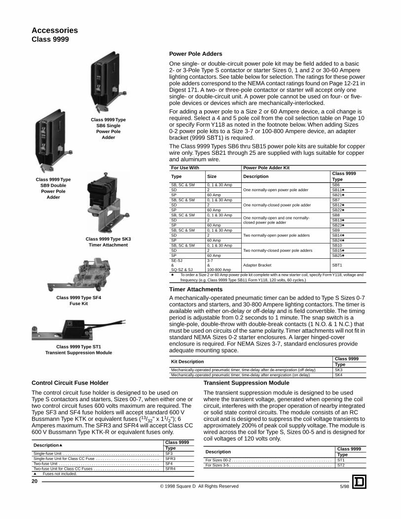
Power Pole Adders
One single- or double-circuit power pole kit may be field added to a basic2- or 3-Pole Type S contactor or starter Sizes 0, 1 and 2 or 30-60 Ampere lighting contactors. See table below for selection. The ratings for these power pole adders correspond to the NEMA contact ratings found on Page 12-21 in Digest 171. A two- or three-pole contactor or starter will accept only one single- or double-circuit unit. A power pole cannot be used on four- or five-pole devices or devices which are mechanically-interlocked.For adding a power pole to a Size 2 or 60 Ampere device, a coil change is required. Select a 4 and 5 pole coil from the coil selection table on Page 10 or specify Form Y118 as noted in the footnote below. When adding Sizes 0-2 power pole kits to a Size 3-7 or 100-800 Ampere device, an adapter bracket (9999 SBT1) is required.The Class 9999 Types SB6 thru SB15 power pole kits are suitable for copper wire only. Types SB21 through 25 are supplied with lugs suitable for copper and aluminum wire.
Timer AttachmentsA mechanically-operated pneumatic timer can be added to Type S Sizes 0-7 contactors and starters, and 30-800 Ampere lighting contactors. The timer is available with either on-delay or off-delay and is field convertible. The timing period is adjustable from 0.2 seconds to 1 minute. The snap switch is a single-pole, double-throw with double-break contacts (1 N.O. & 1 N.C.) that must be used on circuits of the same polarity. Timer attachments will not fit in standard NEMA Sizes 0-2 starter enclosures. A larger hinged-cover enclosure is required. For NEMA Sizes 3-7, standard enclosures provide adequate mounting space.
For Use With Power Pole Adder Kit
Type Size DescriptionClass 9999 Type
SB, SC & SM 0, 1 & 30 AmpOne normally-open power pole adder
SB6SD 2 SB11tSP 60 Amp SB21tSB, SC & SM 0, 1 & 30 Amp
One normally-closed power pole adderSB7
SD 2 SB12tSP 60 Amp SB22tSB, SC & SM 0, 1 & 30 Amp
One normally-open and one normally-closed power pole adder
SB8SD 2 SB13tSP 60 Amp SB23tSB, SC & SM 0, 1 & 30 Amp
Two normally-open power pole addersSB9
SD 2 SB14tSP 60 Amp SB24tSB, SC & SM 0, 1 & 30 Amp
Two normally-closed power pole addersSB10
SD 2 SB15tSP 60 Amp SB25tSE-SJ&SQ-SZ & SJ
3-7&100-800 Amp
Adapter Bracket SBT1
t To order a Size 2 or 60 Amp power pole kit complete with a new starter coil, specify Form Y118, voltage and frequency (e.g. Class 9999 Type SB11 Form Y118, 120 volts, 60 cycles.)
Kit DescriptionClass 9999Type
Mechanically-operated pneumatic timer, time-delay after de-energization (off delay) SK3Mechanically-operated pneumatic timer, time-delay after energization (on delay) SK4
Control Circuit Fuse Holder
The control circuit fuse holder is designed to be used on Type S contactors and starters, Sizes 00-7, when either one or two control circuit fuses 600 volts maximum are required. The Type SF3 and SF4 fuse holders will accept standard 600 V Bussmann Type KTK or equivalent fuses (13/32" x 11/2"); 6 Amperes maximum. The SFR3 and SFR4 will accept Class CC 600 V Bussmann Type KTK-R or equivalent fuses only.
Transient Suppression Module
The transient suppression module is designed to be used where the transient voltage, generated when opening the coil circuit, interferes with the proper operation of nearby integrated or solid state control circuits. The module consists of an RC circuit and is designed to suppress the coil voltage transients to approximately 200% of peak coil supply voltage. The module is wired across the coil for Type S, Sizes 00-5 and is designed for coil voltages of 120 volts only.
DescriptionqClass 9999Type
Single-fuse Unit . . . . . . . . . . . . . . . . . . . . . . . . . . . . . . . . . . . . . . . . . . . . SF3Single-fuse Unit for Class CC Fuse . . . . . . . . . . . . . . . . . . . . . . . . . . . . . SFR3Two-fuse Unit . . . . . . . . . . . . . . . . . . . . . . . . . . . . . . . . . . . . . . . . . . . . . . SF4Two-fuse Unit for Class CC Fuses . . . . . . . . . . . . . . . . . . . . . . . . . . . . . . SFR4q Fuses not included.
DescriptionClass 9999Type
For Sizes 00-2 . . . . . . . . . . . . . . . . . . . . . . . . . . . . . . . . . . . . . . . . . . . . . . ST1For Sizes 3-5 . . . . . . . . . . . . . . . . . . . . . . . . . . . . . . . . . . . . . . . . . . . . . . . ST2
Class 9999 Type SB6 Single Power Pole
Adder
Class 9999 Type SB9 Double Power Pole
Adder
Class 9999 Type SK3Timer Attachment
Class 9999 Type SF4Fuse Kit
Class 9999 Type ST1Transient Suppression Module
215/98 © 1998 Square D All Rights Reserved
AccessoriesClass 9999
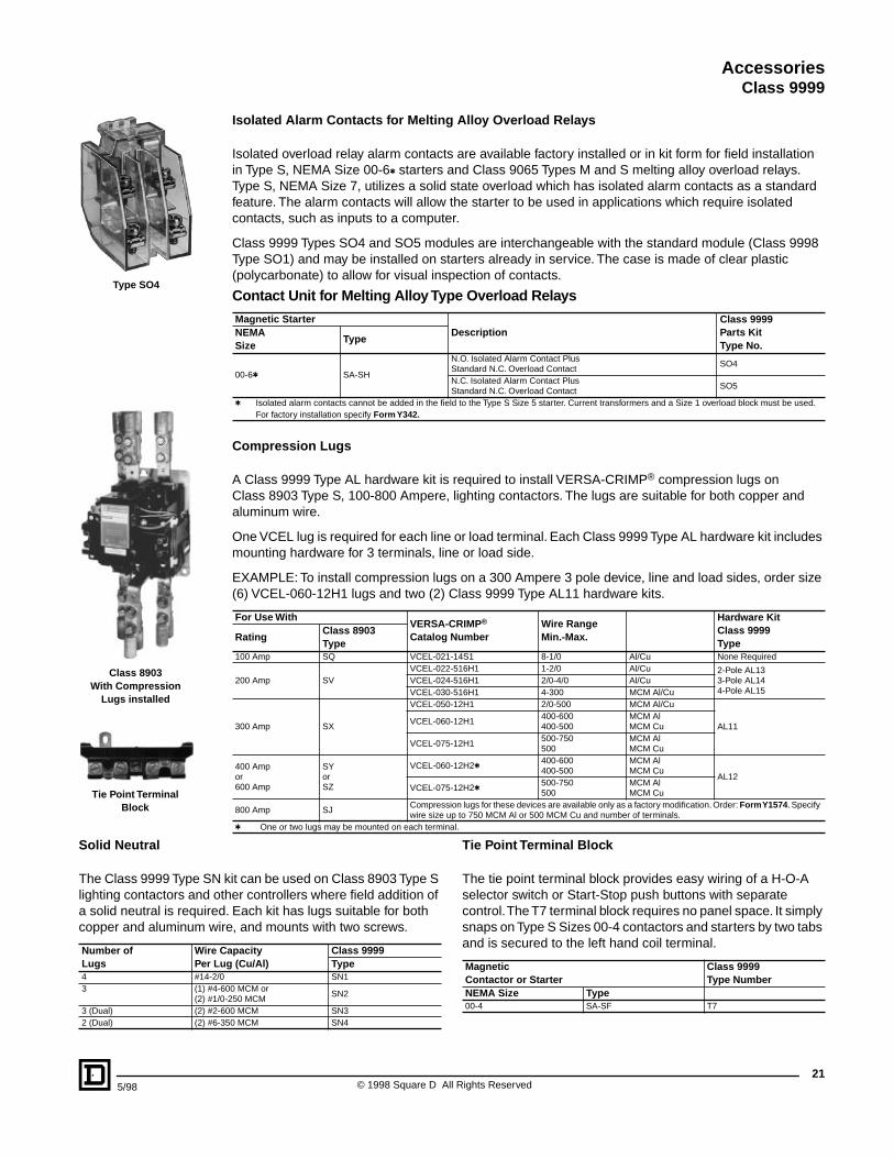
Isolated Alarm Contacts for Melting Alloy Overload Relays
Isolated overload relay alarm contacts are available factory installed or in kit form for field installation in Type S, NEMA Size 00-6t starters and Class 9065 Types M and S melting alloy overload relays. Type S, NEMA Size 7, utilizes a solid state overload which has isolated alarm contacts as a standard feature. The alarm contacts will allow the starter to be used in applications which require isolated contacts, such as inputs to a computer.
Class 9999 Types SO4 and SO5 modules are interchangeable with the standard module (Class 9998 Type SO1) and may be installed on starters already in service. The case is made of clear plastic (polycarbonate) to allow for visual inspection of contacts.
Compression Lugs
A Class 9999 Type AL hardware kit is required to install VERSA-CRIMP® compression lugs on Class 8903 Type S, 100-800 Ampere, lighting contactors. The lugs are suitable for both copper and aluminum wire.
One VCEL lug is required for each line or load terminal. Each Class 9999 Type AL hardware kit includes mounting hardware for 3 terminals, line or load side.
EXAMPLE: To install compression lugs on a 300 Ampere 3 pole device, line and load sides, order size (6) VCEL-060-12H1 lugs and two (2) Class 9999 Type AL11 hardware kits.
Contact Unit for Melting Alloy Type Overload Relays
Magnetic StarterDescription
Class 9999Parts KitType No.
NEMASize
Type
00-6t SA-SH
N.O. Isolated Alarm Contact PlusStandard N.C. Overload Contact
SO4
N.C. Isolated Alarm Contact PlusStandard N.C. Overload Contact
SO5
t Isolated alarm contacts cannot be added in the field to the Type S Size 5 starter. Current transformers and a Size 1 overload block must be used. For factory installation specify Form Y342.
For Use WithVERSA-CRIMP®
Catalog NumberWire RangeMin.-Max.
Hardware KitClass 9999Type
RatingClass 8903Type
100 Amp SQ VCEL-021-14S1 8-1/0 Al/Cu None Required
200 Amp SVVCEL-022-516H1 1-2/0 Al/Cu 2-Pole AL13
3-Pole AL144-Pole AL15
VCEL-024-516H1 2/0-4/0 Al/CuVCEL-030-516H1 4-300 MCM Al/Cu
300 Amp SX
VCEL-050-12H1 2/0-500 MCM Al/Cu
AL11VCEL-060-12H1
400-600400-500
MCM AlMCM Cu
VCEL-075-12H1500-750500
MCM AlMCM Cu
400 Ampor600 Amp
SYorSZ
VCEL-060-12H2t400-600400-500
MCM AlMCM Cu
AL12VCEL-075-12H2t
500-750500
MCM AlMCM Cu
800 Amp SJCompression lugs for these devices are available only as a factory modification. Order: Form Y1574. Specify wire size up to 750 MCM Al or 500 MCM Cu and number of terminals.
t One or two lugs may be mounted on each terminal.
Solid Neutral
The Class 9999 Type SN kit can be used on Class 8903 Type S lighting contactors and other controllers where field addition of a solid neutral is required. Each kit has lugs suitable for both copper and aluminum wire, and mounts with two screws.
Tie Point Terminal Block
The tie point terminal block provides easy wiring of a H-O-A selector switch or Start-Stop push buttons with separate control. The T7 terminal block requires no panel space. It simply snaps on Type S Sizes 00-4 contactors and starters by two tabs and is secured to the left hand coil terminal.
Number ofLugs
Wire CapacityPer Lug (Cu/Al)
Class 9999 Type
4 #14-2/0 SN13 (1) #4-600 MCM or
(2) #1/0-250 MCMSN2
3 (Dual) (2) #2-600 MCM SN32 (Dual) (2) #6-350 MCM SN4
MagneticContactor or Starter
Class 9999Type Number
NEMA Size Type 00-4 SA-SF T7
Tie Point Terminal Block
Class 8903With Compression
Lugs installed
Type SO4
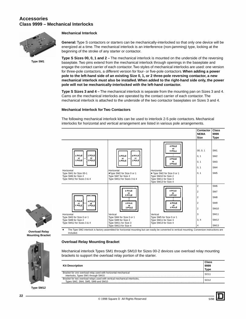
© 1998 Square D All Rights Reserved22
5/98
AccessoriesClass 9999 – Mechanical Interlocks
Mechanical Interlock
General: Type S contactors or starters can be mechanically-interlocked so that only one device will be energized at a time. The mechanical interlock is an interference (non-jamming) type, locking at the beginning of the stroke of any starter or contactor.
Type S Sizes 00, 0, 1 and 2 – The mechanical interlock is mounted on the underside of the reversing baseplate. Two pins extend from the mechanical interlock through openings in the baseplate and engage the contact carrier of each contactor. Two styles of mechanical interlocks are used: one version for three-pole contactors, a different version for four- or five-pole contactors. When adding a power pole to the left-hand side of an existing Size 0, 1, or 2 three-pole reversing contactor, a new mechanical interlock must also be installed. When added to the right-hand side only, the power pole will not be mechanically-interlocked with the left-hand contactor.
Type S Sizes 3 and 4 – The mechanical interlock is separate from the mounting pan on Sizes 3 and 4. Cams on the mechanical interlocks are operated by the contact carrier of each contactor. The mechanical interlock is attached to the underside of the two contactor baseplates on Sizes 3 and 4.
Mechanical Interlock for Two Contactors
The following mechanical interlock kits can be used to interlock 2-5 pole contactors. Mechanical interlocks for horizontal and vertical arrangement are listed in various pole arrangements.
Overload Relay Mounting Bracket
Mechanical interlock Types SM1 through SM10 for Sizes 00-2 devices use overload relay mounting brackets to support the overload relay portion of the starter.
ContactorNEMASize
Class9999Type
HorizontalType SM1 for Size 00-1Type SM6 for Size 2Type SM12 for Sizes 3 & 4
HorizontaltType SM2 for Size 0 or 1Type SM7 for Size 2Type SM12 for Sizes 3 & 4
Horizontalt Type SM2 for Size 0 or 1Type SM10 for Size 2Type SM11 for Size 3Type SM13 for Size 4
00, 0, 1
0, 1
0, 1
0, 1
0, 1
SM1
SM2
SM3
SM4
SM5
HorizontalType SM3 for Size 0 or 1Type SM8 for Size 2Type SM12 for Sizes 3 & 4
VerticalType SM4 for Size 0 or 1Type SM9 for Size 2Type SM11 for Size 3Type SM13 for Size 4
VerticalType SM5 for Size 0 or 1Type SM11 for Size 3Type SM13 for Size 4
2
2
2
2
2
3
3, 4
4
SM6
SM7
SM8
SM9
SM10
SM11
SM12
SM13
t The Type SM2 interlock is factory assembled for horizontal mounting but can easily be converted to vertical mounting. Conversion instructions are included.
Kit DescriptionClass9999Type
Bracket for one overload relay used with horizontal mechanical interlocks, Types SM1 through SM10. . . . . . . . . . . . . . . . . . . . . . . . . . . . . . . . . . . . . . . . . . . . . . . . . . . . . . . . . . . . . . . . . . . . . . . . .
SO11
Bracket for two overload relays used with vertical mechanical interlocks,Types SM2, SM4, SM5, SM9 and SM10 . . . . . . . . . . . . . . . . . . . . . . . . . . . . . . . . . . . . . . . . . . . . . . . . . . . . . . . . . . . . . . . . . . . . . .
SO12
Type SM1
Type SM12
Overload Relay Mounting Bracket

235/98 © 1998 Square D All Rights Reserved
AccessoriesFuse Block Replacement Parts Kits – Class 9422/9999
Class 9422 Replacement Fuse Clip Kits
Class 8538 (Series D and newer), Class 8738 (Series E and newer), and Class 8903 (Series C and newer) Type S non-fusible combination starters and lighting contactors (sizes 0 – 2, 30 to 60 Amperes) can be converted to the fusible type by installing a Class 9422 Fuse Clip Kit. Both fusible and non-fusible combination devices have the same size enclosure in NEMA Types 1, 4, and 12 construction, which permits this conversion. The 9422 Fuse Clip Kits contain line & load fuse clips, load base, and fuse pullers.
Class 9999 Replacement Fuse Block Kit and Mounting Brackets for8538 Pre-Series D and 8738 Pre-Series E Fuse Blocks
Note that the fuse clips ARE NOT included with the fuse block and should be ordered separately using the table shown below.
DeviceUsed On
DisconnectAmpereRating
NEMA Class H, K, J, R FusesClass RFuse Clip Kits
Fuse Clip Ratings-AmperesClass & Type
Size or Ampere Rating 250 V Max. 600 V Max.0, 1 & 30 Amp 30 0 – 30 — 9422TC30k RFK03a0, 1 & 30 Amp 30 31 – 60 0 – 30 9422TC33k RFK06a2 & 60 Amp 60 31 – 60 0 – 30 9422TC33 RFK06a2 & 60 Amp 60 — 31 – 60 9422TD63 RFK06Hak When using with a 9422 FTCN or FTCF disconnect switch in 8538 or 8738 combination starters, remove and discard metal base plate.a No Class Number required.
Kit Description (Fuse Clips Not Included) SizeClass 9999Type
Fuse block kit to convert disconnect switch in Class 8538, 8738 and 8903 combination starters and contactors from non-fusible to fusible. Does not include fuse clips.
0, 1 &30 Amp2 & 60 Amp
SF1cSF2c
Two mounting brackets plus hardware for elevating power fuse block in Class 8538 Size 0 and 1 fusible combination starters and 8903, 30 Amp contactor.
..... SF11c
c Cannot be used in 8538 Series D and newer or 8738 Series E and newer for Class 8538 pre-Series D and 8738 pre-Series E
Class 9999 Replacement Fuse Clip Kits
DeviceUsed On
DisconnectAmpereRating
NEMA Class H Fuses NEMA Class R Fuses NEMA Class J FusesFuse ClipRatings-Amperes
Type
Fuse ClipRatings-Amperes
Type
Fuse ClipRating Amperes600 V Max.
TypeSize orAmpere Rating
250 VMax.
600 VMax.
250 VMax.
600 VMax.
0, 1 & 30 Amp0, 1 & 30 Amp
303030
0-30. . . .31-60
. . . .0-300-30
S1S2S2
0-30. . . .31-60
. . . .0-300-30
SR1SR2SR2
. . . .0-300-30
. . .SJ2SJ2
2 & 60 Amp2 & 60 Amp
6060
31-60. . . .
0-3031-60
S2S3
31-60. . . .
0-3031-60
SR2SR3
0-3031-60
SJ2SJ3
3 & 100 Amp3 & 100 Amp
100100
61-100101-200
61-100. . . .
S4fS5f
61-100101-200
61-100. . . .
SR4tSR4t
61-100101-200
SJ4SJ5
4 & 200 Amp 200 101-200 101-200 S5f 101-200 101-200 SR4t 101-200 SJ55 & 300 Amp 400 . . . . . . . . . . . . 201-400 201-400 SR5t . . . . . . .6 & 400, 600 Amp 600 . . . . . . . . . . . . 401-600 401-600 SR5t . . . . . . .t Fuse clips are not provided in the Type SR4 and SR5 kits. On new installations Class 9999 Type S fuse clips must also be purchased. Three non-
removable pins are supplied and can be installed only in the latest production devices which have a hole in the lower fuse clips.f Cannot be used in Series B or newer 8538s.
Class 9999 Auxiliary Contact Kits for Disconnect Switches and Circuit Breakers
Class TypeSPDT DPDTType Type
8538 SBq, SCq, SDq (Series B) R6 R78538, 8738 SD (Series C) R43 R448538, 8738 SB, SC (Series C)
R45 R469422 TC9422 TD R43 R448538, 8738 SE, SF (Series A)
R8 R99422 TF8538, 8738 SE (Series B & C)
R41 R429422 TE8538, 8738 SF (Series B & C) R39 R408538, 8738 SG R35 R36q Class 8538 type numbers ending in suffix “S8”.
Class TypeSPDT DPDTType Type
8539, 8739 SB, SC, SD, SE, SF, SGcR26 R27
9422 RN, RP, RR, RT9421 FN, FP, FR, FT R18 R199421 LF, LK, LL, LM, LN, LP, LR, LT R47 R489422 TCF, TCN, TDF, TDN, TEF, TEN TC10 TC209422 BTCF, BTCN, BTDF, BTDN, BTEF, BTEN TC11 TC218538 SBA, SCA, SBG, SCG (Series D) TC11 TC218538 SBAS8, SCAS8, SBGS8, SCGS8 (Series D) TC10 TC208738 SBA, SCA, SBG, SCG (Series E) TC11 TC218538 SDA, SDAq, SDG, SDGq (Series D) TC10 TC208738 SDA, SDG (Series E) TC10 TC208538, 8738 SEA, SEG (Series D) TC10 TC20c No auxiliary contacts are available for GJL circuit breaker.q Class 8538 type numbers ending in suffix “S8”.
For additional information on Class 9422, reference Catalog # 9420CT9701 or D-FAX™ # 1501.
Class 9999 Type TC10
Class 9999 Type S2Interchangeable Fuse Clips
Class 9422 TC33Fuse Block

Catalog No. 9999CT9701 May 98 © 1998 Square D All Rights Reserved.
ISO-FLEX, Square D and are registered trademarks of Square D Company.VERSA-CRIMP is a registered trademark of Hubbell Incorporated.VITON is a registered trademark of E.I. DuPont.
Square D Company8001 Highway 64 EastKnightdale, NC 27545 USA(919) 266-3671


![Construction of Adjacent Spiro-quaternary and Tertiary ...CP1,[1] CP2,[1] CP4,[2] CP5,[2] CP6,[3] were prepared according to the previously reported procedures. All allenoates[4] and](https://static.fdocuments.in/doc/165x107/5fb77b0770e3d04e1815e82b/construction-of-adjacent-spiro-quaternary-and-tertiary-cp11-cp21-cp42.jpg)