Type precast
11
PRECAST CONCRETE CONSTRUCTION Svetlana Brzev, British Columbia Institute of Technology, Canada Teresa Guevara-Perez, Architect, Venezuela BACKGROUND The concept of precast (also known as “prefabricated”) construction includes those buildings where the majority of structural components are standardized and produced in plants in a location away from the building, and then transported to the site for assembly. These components are manufactured by industrial methods based on mass production in order to build a large number of buildings in a short time at low cost. The main features of this construction process are as follows: • The division and specialization of the human workforce • The use of tools, machinery, and other equipment, usually automated, in the production of standard, interchangeable parts and products This type of construction requires a restructuring of the entire conventional construction process to enable interaction between the design phase and production planning in order to improve and speed up the construction. One of the key premises for achieving that objective is to design buildings with a regular configuration in plan and elevation. Urban residential buildings of this type are usually five to ten stories high (see Figures 1 and 2). Many countries used various precast building systems during the second half of the 20 th century to provide low-income housing for the growing urban population. They were very popular after the Second World War, especially in Eastern European countries and former Soviet Union republics. In the former Soviet Union, different precast buildings systems are denoted as “Seria,” whereas in Romania they are called “Secţiunea.” In general, precast building systems are more economical when compared to conventional multifamily residential construction (apartment buildings) in many countries. The reader is referred to the UNIDO 2 report for detailed coverage on precast systems and their earthquake resistance. Figure 1: Typical large-panel buildings in Kyrgyzstan (WHE Report 38) and Russian Federation (WHE Report 55)
-
Upload
ramin-vaghei -
Category
Engineering
-
view
38 -
download
0
Transcript of Type precast

�
PRECAST CONCRETE CONSTRUCTION Svetlana Brzev, British Columbia Institute of Technology, Canada
Teresa Guevara-Perez, Architect, Venezuela
BACKGROUND
The concept of precast (also known as “prefabricated”) construction includes those buildings where the majority of structural components are standardized and produced in plants in a location away from the building, and then transported to the site for assembly. These components are manufactured by industrial methods based on mass production in order to build a large number of buildings in a short time at low cost. The main features of this construction process are as follows: �
• The division and specialization of the human workforce• The use of tools, machinery, and other equipment, usually automated, in the
production of standard, interchangeable parts and products
This type of construction requires a restructuring of the entire conventional construction process to enable interaction between the design phase and production planning in order to improve and speed up the construction. One of the key premises for achieving that objective is to design buildings with a regular configuration in plan and elevation.
Urban residential buildings of this type are usually five to ten stories high (see Figures 1 and 2). Many countries used various precast building systems during the second half of the 20th century to provide low-income housing for the growing urban population. They were very popular after the Second World War, especially in Eastern European countries and former Soviet Union republics. In the former Soviet Union, different precast buildings systems are denoted as “Seria,” whereas in Romania they are called “Secţiunea.”
In general, precast building systems are more economical when compared to conventional multifamily residential construction (apartment buildings) in many countries. The reader is referred to the UNIDO2 report for detailed coverage on precast systems and their earthquake resistance.
Figure 1: Typical large-panel buildings in Kyrgyzstan (WHE Report 38) and Russian Federation (WHE Report 55)
2
Precast Concrete Construction
CATEGORIES OF PRECAST BUILDING SYSTEMS
Precast buildings constitute a significant fraction of the building stock in the republics of the former Soviet Union and Eastern European countries. These systems have been described in the following eight WHE reports: 32 (Kazakhstan); 33, 38, and 39 (Kyrgyzstan); 55 (Russian Federation); 66 (Uzbekistan); 68 (Serbia and Montenegro); and 83 (Romania).
Depending on the load-bearing structure, precast systems described in the WHE can be divided into the following categories:
• Large-panel systems• Frame systems• Slab-column systems with walls• Mixed systems
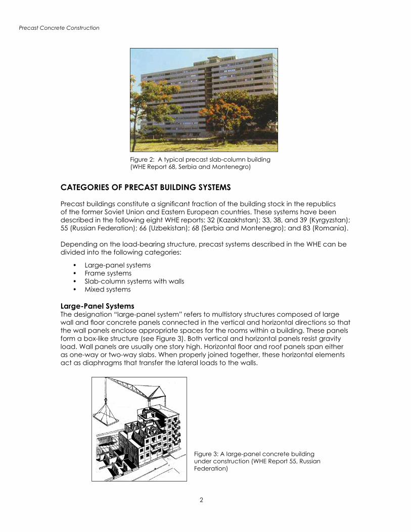
Large-Panel SystemsThe designation “large-panel system” refers to multistory structures composed of large wall and floor concrete panels connected in the vertical and horizontal directions so that the wall panels enclose appropriate spaces for the rooms within a building. These panels form a box-like structure (see Figure 3). Both vertical and horizontal panels resist gravity load. Wall panels are usually one story high. Horizontal floor and roof panels span either as one-way or two-way slabs. When properly joined together, these horizontal elements act as diaphragms that transfer the lateral loads to the walls.
Figure 2: A typical precast slab-column building (WHE Report 68, Serbia and Montenegro)
Figure 3: A large-panel concrete building under construction (WHE Report 55, Russian Federation)

Precast Concrete Construction
3
Depending on the wall layout, there are three basic configurations of large-panel buildings:
• Cross-wall system. The main walls that resist gravity and lateral loads are placed in the short direction of the building.
• Longitudinal-wall system. The walls resisting gravity and lateral loads are placed in the longitudinal direction; usually, there is only one longitudinal wall, except for the system with two longitudinal walls developed in Kazakhstan (WHE Report 32).
• Two-way system. The walls are placed in both directions (Romania, WHE Report 83).
Thickness of wall panels ranges from 120 mm for interior walls (Kyrgyzstan, WHE report 38) to 300 mm for exterior walls (Kazakhstan, WHE Report 32). Floor panel thickness is 60 mm (Kyrgyzstan). Wall panel length is equal to the room length, typically on the order of 2.7 m to 3.6 m. In some cases, there are no exterior wall panels and the façade walls are made of lightweight concrete (Romania, WHE Report 83). A typical interior wall panel is shown in Figure 4.
Panel connections represent the key structural components in these systems. Based on their location within a building, these connections can be classified into vertical and horizontal joints. Vertical joints connect the vertical faces of adjoining wall panels and primarily resist vertical seismic shear forces. Horizontal joints connect the horizontal faces of the adjoining wall and floor panels and resist both gravity and seismic loads.
Depending on the construction method, these joints can be classified as wet and dry. Wet joints are constructed with cast-in-place concrete poured between the precast panels. To ensure structural continuity, protruding reinforcing bars from the panels (dowels) are welded, looped, or otherwise connected in the joint region before the concrete is placed. Dry joints are constructed by bolting or welding together steel plates or other steel inserts cast into the ends of the precast panels for this purpose. Wet joints more closely approximate cast-in-place construction, whereas the force transfer in structures with dry joints is accomplished at discrete points.
Figure 4: Precast interior wall panel with steel dowels and grooves (WHE Report 38, Kyrgyzstan)

4
Precast Concrete Construction
Figure 5 shows a plan of a large-panel building from Kazakhstan with the connection details. In this system, vertical wall panel connections are accomplished by means of groove joints, which consist of a continuous void between the panels with lapping horizontal steel and vertical tie-bars. Horizontal joint reinforcement consists of dowels projected from the panels and the hairpin hooks site-welded to the dowels; the welded length of the lapped bars depends on the bar diameter and the steel grade. Vertical tie-bars are designed for tension forces developed at the panel intersections.
Lateral stability of a large-panel building system typical for Romania is provided by the columns tied to the wall panels (WHE Report 83). Boundary elements (called “bulbs” in Romania) are used instead of the columns as “stiffening” elements at the exterior, as shown in Figure 6. The unity of wall panels is achieved by means of splice bars welded to the transverse reinforcement of adjacent panels in the vertical joints. Longitudinal dowel
Figure 5: Plan of a large-panel building showing vertical connection details (WHE Report 32, Kazakhstan)
Figure 6: A typical building plan showing the locations of boundary members (WHE Report 83, Romania)
Precast Concrete Construction
5
bars placed in vertical and horizontal joints provide an increase in bearing area for the transfer of tension across the connections. Wall-to-floor connection is similar to that shown in Figure 5.
Frame Systems
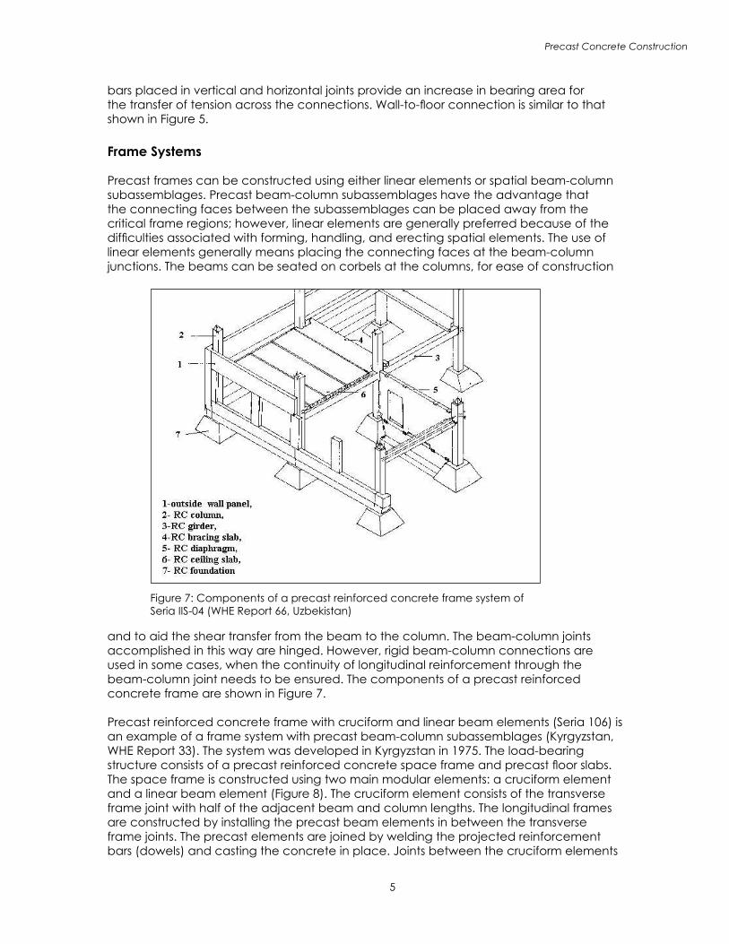
Precast frames can be constructed using either linear elements or spatial beam-column subassemblages. Precast beam-column subassemblages have the advantage that the connecting faces between the subassemblages can be placed away from the critical frame regions; however, linear elements are generally preferred because of the difficulties associated with forming, handling, and erecting spatial elements. The use of linear elements generally means placing the connecting faces at the beam-column junctions. The beams can be seated on corbels at the columns, for ease of construction
and to aid the shear transfer from the beam to the column. The beam-column joints accomplished in this way are hinged. However, rigid beam-column connections are used in some cases, when the continuity of longitudinal reinforcement through the beam-column joint needs to be ensured. The components of a precast reinforced concrete frame are shown in Figure 7.
Precast reinforced concrete frame with cruciform and linear beam elements (Seria 106) is an example of a frame system with precast beam-column subassemblages (Kyrgyzstan, WHE Report 33). The system was developed in Kyrgyzstan in 1975. The load-bearing structure consists of a precast reinforced concrete space frame and precast floor slabs. The space frame is constructed using two main modular elements: a cruciform element and a linear beam element (Figure 8). The cruciform element consists of the transverse frame joint with half of the adjacent beam and column lengths. The longitudinal frames are constructed by installing the precast beam elements in between the transverse frame joints. The precast elements are joined by welding the projected reinforcement bars (dowels) and casting the concrete in place. Joints between the cruciform elements
Figure 7: Components of a precast reinforced concrete frame system of Seria IIS-04 (WHE Report 66, Uzbekistan)

6
Precast Concrete Construction
are located at the mid-span of beams and columns, whereas the longitudinal precast beam-column connections are located close to the columns. Hollow-core precast slabs are commonly used for floor and roof structures in this type of construction, as shown in Figure 9.
Slab-Column Systems with Shear WallsThese systems rely on shear walls to sustain lateral load effects, whereas the slab-column structure resists mainly gravity loads. There are two main systems in this category:
• Lift-slab system with walls• Prestressed slab-column system
Lift-slab systems were introduced in the last decade of the Soviet Union (period 1980-1989) in some of the Soviet Republics, including Kyrgyzstan, Tadjikistan, and the
Figure 8: A perspective drawing showing cruciform and linear units (WHE Report 33, Kyrgyzstan)
Figure 9: Hollow-core precast slab (WHE Report 33, Kyrgyzstan)

Precast Concrete Construction
7
Figure 10: A lift-slab building of “Seria KUB” under construction (WHE Report 39, Kyrgyzstan)
Figure 11: Plan of a typical lift-slab building (WHE Report 39, “Seria KUB,” Kyrgyzstan)
Caucasian region of Russia, etc. This type of precast construction is known as “Seria KUB.” The load-bearing structure consists of precast reinforced concrete columns and slabs, as shown in Figure 10. Precast columns are usually two stories high. All precast structural elements are assembled by means of special joints. Reinforced concrete slabs are
8
Precast Concrete Construction
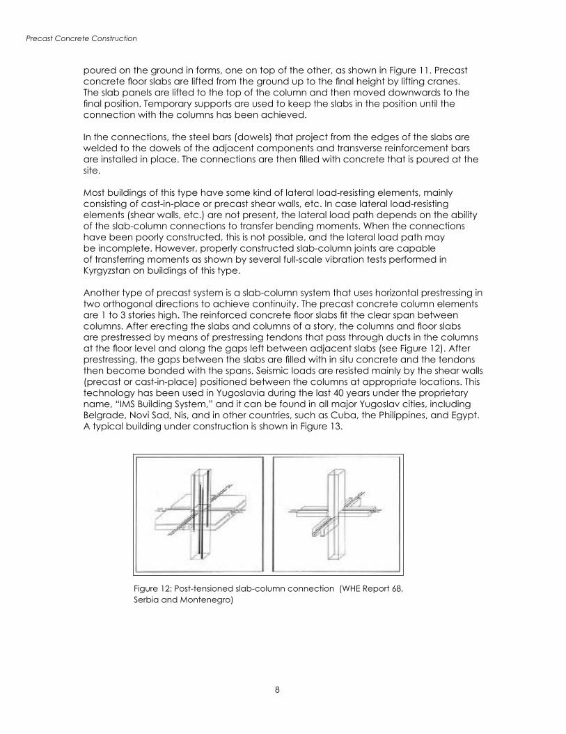
Figure 12: Post-tensioned slab-column connection (WHE Report 68, Serbia and Montenegro)
poured on the ground in forms, one on top of the other, as shown in Figure 11. Precast concrete floor slabs are lifted from the ground up to the final height by lifting cranes. The slab panels are lifted to the top of the column and then moved downwards to the final position. Temporary supports are used to keep the slabs in the position until the connection with the columns has been achieved.
In the connections, the steel bars (dowels) that project from the edges of the slabs are welded to the dowels of the adjacent components and transverse reinforcement bars are installed in place. The connections are then filled with concrete that is poured at the site.
Most buildings of this type have some kind of lateral load-resisting elements, mainly consisting of cast-in-place or precast shear walls, etc. In case lateral load-resisting elements (shear walls, etc.) are not present, the lateral load path depends on the ability of the slab-column connections to transfer bending moments. When the connections have been poorly constructed, this is not possible, and the lateral load path may be incomplete. However, properly constructed slab-column joints are capable of transferring moments as shown by several full-scale vibration tests performed in Kyrgyzstan on buildings of this type.
Another type of precast system is a slab-column system that uses horizontal prestressing in two orthogonal directions to achieve continuity. The precast concrete column elements are 1 to 3 stories high. The reinforced concrete floor slabs fit the clear span between columns. After erecting the slabs and columns of a story, the columns and floor slabs are prestressed by means of prestressing tendons that pass through ducts in the columns at the floor level and along the gaps left between adjacent slabs (see Figure 12). After prestressing, the gaps between the slabs are filled with in situ concrete and the tendons then become bonded with the spans. Seismic loads are resisted mainly by the shear walls (precast or cast-in-place) positioned between the columns at appropriate locations. This technology has been used in Yugoslavia during the last 40 years under the proprietary name, “IMS Building System,” and it can be found in all major Yugoslav cities, including Belgrade, Novi Sad, Nis, and in other countries, such as Cuba, the Philippines, and Egypt. A typical building under construction is shown in Figure 13.

Precast Concrete Construction
9
Figure 13: Assembly of precast columns in progress (WHE Report 68, Serbia and Montenegro)
EARTHQUAKE PERFORMANCE
There is a general concern among the earthquake engineering community regarding the seismic performance of precast construction. Based on experience in past earthquakes in Eastern European and in Central Asian countries where these systems have been widely used, it can be concluded that their seismic performance has been fairly satisfactory. However, when it comes to earthquake performance, the fact is that “bad news” is more widely publicized than “good news.” For example, the poor performance of precast frame systems of Seria 111 in the 1988 Spitak (Armenia) (M7.5) earthquake is well known (see Figure 14). However, few engineers are aware of the good seismic performance (no damage) of several large-panel buildings under construction at the same site, as shown in Figure 15; these large-panel buildings were of a similar seria as the large-panel buildings described in the WHE Report 55 from the Russian Federation (Seria 464). The buildings of Seria 111 were similar to the precast concrete frame system of Seria IIS, described in the WHE report 66 (Uzbekistan).
The precast prestressed slab-column system (IMS Building System) described in WHE Report 68 (Serbia and Montenegro) has undergone extensive laboratory testing that predicted excellent resistance under simulated seismic loading. These building have been subjected to several moderate earthquakes without experiencing significant damage.
Due to their large wall density and box-like structure, large-panel buildings are very stiff and are characterized with a rather small fundamental period. For example, a 9-story building in Kazakhstan has a fundamental period of 0.35 to 0.4 sec (WHE Report 32). In general, large-panel buildings performed very well in the past earthquakes in the former Soviet Union, including the 1988 Armenia earthquake and the1976 Gazly earthquakes

�0
Precast Concrete Construction
Figure 14: Building collapse in the 1988 Spitak (Armenia) earthquake (WHE Report 66, Uzbekistan)
Figure 15: Large-panel concrete buildings remained undamaged in the 1988 Spitak (Armenia) earthquake (far back), whereas the precast frame buildings suffered extensive damage (foreground)3 (WHE Report 32, Kazakhstan)
(Uzbekistan). It should be noted, however, that large-panel buildings in the area affected by the 1976 Gazly earthquakes were not designed with seismic provisions. Most such buildings performed well in the first earthquake (M 7.0), but more damage was observed in the second earthquake that occurred the same year (M 7.3), as some buildings had been already weakened by the first earthquake (Russian Federation, WHE Report 55). Large-panel buildings performed well in the 1977 Vrancea (Romania) earthquake (M 7.2) and in subsequent earthquakes in 1986 and 1990 (Romania, WHE Report 83).

Precast Concrete Construction
��
Figure 16: Seismic strengthening of precast columns with steel straps (WHE Report 66, Uzbekistan)
SEISMIC-STRENGTHENING TECHNOLOGIES
According to WHE reports, no major efforts have been reported regarding seismic strengthening of precast concrete buildings. However, seismic strengthening of precast frame buildings was done in Uzbekistan (WHE Report 66). The techniques used include the installation of steel straps at the column locations (see Figure 16) and reinforcing the joints with steel plates to provide additional lateral confinement of the columns.
ENDNOTES� Definition of “Mass Production” in “Industrial Engineering and Production Management” Britannica Macropaedia, The New Encyclopaedia Britannica, 15th Edition, Vol. 21, p. 204, 1989.2 UNIDO, 1983. Design and Construction of Prefabricated Reinforced Concrete Frame and Shear-Wall Buildings. Building Construction Under Seismic Conditions in the Balkan Region. Volume 2. UNDP/UNIDO Project RER/79/015, Vienna, Austria.3 EERI (1989). Armenia Earthquake Reconnaissance Report. Special Supplement to Earthquake Spectra, El Cerrito, California.