Type designs for small water supply systems - IRC :: Home · PDF file25 m3 r.c. circular...
48
2 0 1 8 0 T Y 381^30 w')^^7 "'""*" Type designs for small water supply systems International Reference Centre J2.Q j -^ClN -p^^ for Community Water Supply and Sanitation vl/ ~J-+ J
Transcript of Type designs for small water supply systems - IRC :: Home · PDF file25 m3 r.c. circular...

2 0 1
8 0 T Y 3 8 1 ^ 3 0
w')^^7 "'""*"
Type designs for small water supply systems
International Reference Centre J2.Q j - ^ C l N - p ^ ^ for Community Water Supply and Sanitation v l / ~J-+J

£ P J2>2
Type designs for small water supply systems
International Reference Centre for Community Water Supply and Sanitation

200 - 0 2 1 - 1 0 " 21 -10 2 1 - 1 0 " 21-10 " 21-10
o o a Q
a s a a
— a — o — » * T * n o — n IT D a V ~ ~V v
DETAILS OF A KING-POST TRUSS
109'-2"
12" SECTION D-D
Paving slabs
Cone mix 1:3:6
SECTION C-C
I J—LH—
215'-3" -4 DETAILS OF PAVING
SLABS
~~™ W 5 - 0 SECTION B-B
U PLAN All dimensions In cm, unless otherwise shown
WATER CATCHMENT AND UNDERGROUND TANK TANZANIA

MS. handl«
520 l%5q,»
LONGITUDINAL SECTION
o c a o
;r =ril J'TjJ; ife^T ;. 150 )
I .
O c 2
- . " '.
_
...... _._ :
c
E * c o a E u
' • - _ : - — —
z
: - • - . . - .
.. . -. -..
, - : _ • : . _ - .
-.":-'"-"-';-—-' -,'-
1 _ — • . - .
Road
1500 \ t o 2 5 0 0
PUMP SHEAD TANK & TOWER
L, 3 0 0 L 150 ' 360 J,
SEDIMENTATION TANK FILTER TANK CLEAN WATER TANK
SECTIONAL PLAN AM dimension* In cm, unlet• otherwise shown
FILTER UNIT FOR DOMESTIC CANAL WATER SUPPLY SUDAN

Street typical section
Pip*
Walkway
Principal pipe to be located at 0 .5 mrts from curve. Where it doesn't exist locate if a 2 .000 mrts from property In small alleys e 1.50m i from center of street I Where possible pipe should be installed in the North or West Side of streets
15
Mouth • a
t-'-t-'-t
30
Tool for interrupting service and lift box LID Importont: design the mouth in occorddnce to valve types being used
Tool for lifting box LID
35
- ^ Z3
55
V- *=!> = /
I ! I SECTION A-A SECTION B-B
PLAN
House connection osbestos cement Z3" In P.V.C. p > 4" Rast iron 4> % 3 In P.V.C. * 4 " build a sleeve Asb.cem. p < 3"uscsoddle
All dimensions In cm, unless otherwise shown
HOUSE CONNECTION 6.06

GO x 6 0 Monhole with 75 x 6 0 x 75 x 6 0 Cover of Timber
Ventilator
For reinforcement 7 5 x 6 0 Protection Guard made with yl2" 4 Bar welded to to todder at 90 c/c
2"x 3 ' l6"M.S.Ftat»
2"x 3 ' i e " M S - F'oi% UxM *° w o"
„ ! s 4 0 0 x 4 0 0 R.C. Foundation
a l l " t l - H l U 3 m W . y - M W y A - . 430 x 4 3 0 Hordcore Base ' 5oo blinded with 1:6 Mortar on r 1 Upper Surface
6 0 0
Indicator R.C. Roof slab
24 Nos 'e 4 Bars S IS c/c in both directions (Top)
3 Nos V * Bars « 24c/c (Bottom)
For reinforcement
22 Nos ^2 4 Bars e 12 8.14C/C 9 Nos 3 'a "fJ Bars « 24 c/c
ELEVATOR
HALF SECTIONAL DETAIL OF TANK
in both d.rect.ons " < " " ' Wall j f ) b o < h a i r t c t i o n 4 , B o t t o m )
(Bottom}
DETAIL OF FLOOR & ROOF REINFORCEMENT
SECTION A-A
^ 3" Overflow
See detail A
PART TANK AND WALL PLAN DETAIL OF FOUNDATION REINFORCEMENT
25
AA A
/ TMTrrn /•
DETAIL OF SLIDING JOINT BETWEEN WALL & FLOOR SLAB
.y
Cone. 1:3:6 mix 2 1 Plates
!/2f$8or spacer
7cm long at 120 cm interval
M.S.Bar
Edge to be bevelled to suit diameter of tank
DETAIL OF BLOCK- DETAIL OF VENTILATOR & TIMBER WORK COVER
M.S. Rod —
Floating
^
All dlmtntlon* In cm, unlets ofherwhw shown
25 m3 R.C. CIRCULAR WATERTANK ON 6 m HIGH TANZANIA

50 130 50 55 5 0 1= Voriobl*
H—t-m
SECTION A-A SECTION B-B
-I—r *
n
B PLAN
Drainage
DETAIL OF FILTER
All dimension* In cm, untots otherwise shown
INFILTRATION GALLERY 1.07
ECUADOR

6" x 1,V Hardwood planks with t w o coats of bituminous point
7 Courses 1 nos 3 / 8 " t> per course
5 Courses 2 per course
nos 3 / 8 " * '
Concr. mix. 1:3:6
Cone. (mix. 1:3:6)
DETAIL OF BLOCK WORK
3" 0 Overflow
2 0 ' - 0 " Min 3 " * Washout plug to open drain to suit
All dimensions In cm, unless otherwise shown
3" t outlet
PLAN
I " ' I 9 " J
DETAIL OF EMERGENCY VALVE
5 ' - 7 . S "
TJl '2 * M.S. Bar as lifting handles
=*1
I DETAIL OF
LOCKING ARRANGEMENT
LOW HEAD RAPID GRAVITY FILTER WITH PUMP SUMP
Concr. mix 1:1,5 : 3 -
RING REINFORCEMENT WHERE
BROKEN BY PIPE
r 6"x 1,5" Hardwood planks with . \ ^ two coats of bituminous paint
) _ \ 1 h?
- H
DETAIL OF MANHOLE COVER
TANZANIA

Drum or concrttt container ( 2 0 0 L )
Platform toon
Flexible plastic or rubber tube
Taut nylon guidestring
DETAIL OF FLOATING BOWL (SECTION)
Solution
Oiled ceramic bowl
Rubber cork o 4 .4cm
' l j U m m ) Bore gloss 1 / j ' (12 mm) Rubber tube
>g" Bore glatt tube heated and drawn at top end to give o tmaN orifice
DETAIL OF ALTERNATIVE BOWL (SECTION)
FLOATING BOWL SOLUTION FEEDER
3 7 9
Rubber Gasket Wither Nut Metal pipe threaded on outside at bath endt
Sight guage Alternate tight guage transparent plastic tube
J C see detail "A"
Drain (see detail " B " ) I—Tank walls of
" E t e r n i t e " or A t b c t t o t -cement
1 \~ 23
OPEN, RECTANGULAR PLASTIC FLOAT
Notched
Solvent weM Stone ballast
Plastic block with l Y 2 c m ( ' / 8 ) diameter hole drilled full length
PLASTIC ROD WITH V-NOTCH
V-NOTCH CONSTANT-HEAD SOLUTION FEEDER DETAIL OF FLOAT ASSEMBLY All dimensions In cm, unlets otherwise shown
HYPOCHLORITE SOLUTION FEEDERS 3.01

International Reference Centre
ELEVATION RELATIONS
Max. W. Level e l Bottom of sedimentation tank e2 Reformed ground e3 Centre line level of pipe . 125 e4 Centre line level ol inlet pipe e5
BASIC DIMENSIONS
Ground widths Lengths Depth of water
DIAMETERS
Inlet Outlet (by pass) Overflow Drain pipe
LEGEND:
GROUND PLAN
Watte pip« f 2 0 0
SECTION C-C SECTION B-B
M,b2 L (max. 2000 cm) h (max. 155 cm)
d1 d2
d3 = . 150 mm d4 = . 80 mm
To treatment plant 1. Blinding concrete 2. Watertight reinforced concrete 3. Benching to gradient 4. Cement screed 5. Steel cover 6. Wood cover 7. Steel ladder 8. Overtlow 9. Flanged pipes and fittings In chambers 10. Perforated distribution pipe 11. Perforated collection pipe 12. Hand operated valve 13. Make-up piece 14. Blind flange 15. Anchoring
SECTIONAL PLAN All dimensions In cm, unlets otberwtt* shown
SEDIMENTATION TANK

weir for peak flood L variable
INLET TYPES
TYPE
1 2 3 4
DIMENSIONS
1 cm 1 cm
l.Scm 1.5 cm
1.0cm 2 cm 1 em 2 cm
APROX CONTRACTION COEFF.
Simplt Combined grate grate
0 . 4 5 0 . 5 5 0. 4S 0. 55
0 . 3 0 0 .37 0 . 3 0 0 .37
0 40 0.30
" • • ••• i ini i i f i / /l<iiiiiiimim l l l l I I I ~$/ y<{\ 111)
E w A M WAl
SIMPLE GRATE COMBINED GRATE
Bronze bolt 2"large
GRATE AUDIORAGE
FREE WIDTH :15 CM
FREE WIDTH:20 CM
FREE WIDTH:25CM
Free area per lineair meter in cms*
Simple grate
Combined grate
Free width : 25 cms
f 1cm
c Urn
(TypeD
1.200
775
# 1 c m
c 2 c m i
(Type 2)
1 .820
1 .050
# 1.5 cm c icm
(Type3)
9 2 5
6 0 0
f 1.5 cm
c 2 c mi
(Type4>
1.350
850
Free width : 20 cms
4 1 cm c 1 cm (TypeD
9 6 0
G20
d 1cm c2cms (Type 2)
1.300
8 4 0
^ 15cm c 1 cm
(Type 3)
74 0
4 8 0
# 1.5 cm c 1 cm (Type 4)
1 .060
6 8 0
Free width : 15cms
i 1cm c 1cm (TypeD
720
465
f 1cm c2cms (Type 2)
975
630
41.5 cm c 1 cm (Type 3)
5 5 5
360
d 1.5cm
c 2cms
(Type 4 )
810
510
All dimensions in cm, unless otherwise shown
WEIR INTAKE

'Z®?gr 1 '2 Orifice* 10 each row 30 in bottom 20 lateral!
f-shSo
A
SECTION A-A
4-t1
•415
* f-^
310 -f—*—+•
o o o o o o o r -
§88! -§- '
sv.
+t
15 15
—H>—v
43
too
100
PLAN
• i
jft—fry i
FOR WATER TEMP. T » 2 0 C " ' r ^ 2 REMOVAL OF PARTICLES ! . j SIZE 7.5 X 10⁻¹ cm \^i
SECTION B-B
10
• ^ 5 ^
-t
15
216
GRIT CHAMBER
1 / 1 6 Steel ploU
L 20 x 20 x 3 mm welded to plate
L 20 x 20 x 3 mm aprox
ENTRANCE CANAL DETAIL
EFFLUENT WEIR DETAIL
All dlmemlone in em, unleit otherwfM ahown

2 0 0
2 0 0
DETAIL H DETAIL G
SECTION C-C
CROSS-SECTION A-A CROSS-SECTION D-D
A-E = Cross sections F = Relnforced-concrete shoe G = Hollow bricks laid sideways. Water enters the filter section I
through the holes in the brick. H = Hollow bricks laid Hat. Water enters the well through small
holes designated by L. See detail H and F. I = Sand filter section between brick walls J = Height of filter section, varies with depth of penetration into ground water K = Relnforced-concrete beams L = Small perforations through bricks H. See detail F. M = Layer of round stones N = Layer of gravel O = Layer of coarse sand P = Iron steps, SO cmm (20 in.) apart Q = Grate made of concrete beams
AMAZON WELL
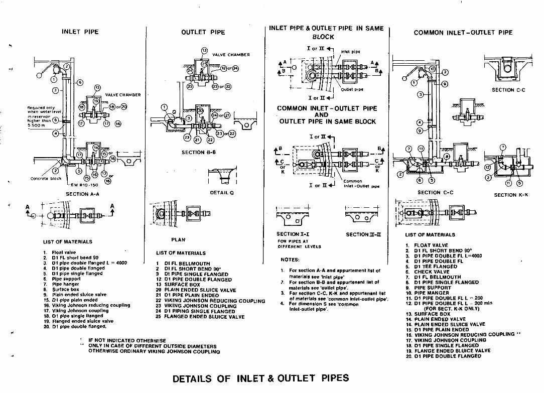
INLET PIPE
Required only when waterJcvel m reservoir --^ «=* higher than ( £ } - J E — 5,500 m
0-4
T—®
« - r r
VALVE CHAMBER
OUTLET PIPE
VALVE CHAMBER
4000
LIST OF MATERIALS
1. Float valve 2. D1 FL short bend 90 3. 01 pipe double flanged L :
4. 01 pipe double flanged 5. D1 pipe single flanged 6. Pipe support 7. Pipe hanger 8. Surface box 9. Plain ended sluice valve 15. D1 pipe plain ended 16. Viking Johnson reducing coupling 17. Viking Johnson coupling 18. D1 pipe single flanged 19. Flanged ended sluice valve 20. D1 pipe double Hanged.
SECTION B-B
DETAIL Q
=ttBxOB3
INLET PIPE & OUTLET PIPE IN SAME BLOCK
PLAN
LIST OF MATERIALS
1 Dl FL BELLMOUTH 2 Dl FL SHORT BEND 90° 3 Dt PIPE SINGLE FLANGED 12 D l PIPE DOUBLE FLANGED 13 SURFACE BOX 20 PLAIN ENDED SLUICE VALVE 21 01 PIPE PLAIN ENDED 22 VIKING JOHNSON REDUCING COUPLING 23 VIKING JOHNSON COUPLING 24 D1 PIPING SINGLE FLANGED 25 FLANGED ENDED SLUICE VALVE
IF NOT INDICATED OTHERWISE ONLY IN CASE OF DIFFERENT OUTSIDE DIAMETERS OTHERWISE ORDINARY VIKING JOHNSON COUPLING
l o r U «-| Inlet pipe
rq1 /
II iorn«-i
fcfljpMq .!*
Outlet pipe
COMMON INLET-OUTLET PIPE AND
OUTLET PIPE IN SAME BLOCK
IorH"
tf.-ft _ ^ L _ _ B4>
OxOTU-b^ =J K
• Common I or H - 4 - 1 Inlet-outlet pipe
t - -4-a J i a i I I U L I I A
SECTION I - I FOR PIPES AT DIFFERENT LEVELS
SECTION n-n
NOTES:
1. For section A-A and appurtement list of materials see 'Inlet pipe'
?. For section B-B and appurtenant list of materials see 'outlet pipe'.
3. For section C-C, K-K and appurtenant list of materials see 'common inlel-oullel pipe'.
4. For dimension S see 'common Inlet-outlet pipe'.
COMMON INLET-OUTLET PIPE
©--T--©
SECTION C-C
SECTION C-C SECTION K-K
LIST OF MATERIALS
1. FLOAT VALVE 2. D l FL SHORT BEND 90° 3. D l PIPE DOUBLE FL L=4000 4. D l PIPE DOUBLE FL 5. D1 TEE FLANGED 6. CHECK VALVE 7. D l FL BELLMOUTH 8. D1 PIPE SINGLE FLANGED 9. PIPE SUPPORT 10. PIPE MANGER 11. D1 PIPE DOUBLE FL L = 200 12. D1 PIPE DOUBLE FL L = 200 min
(FOR SECT. K-K ONLY) 13. SURFACE BOX 14. PLAIN ENDED VALVE 14. PLAIN ENDED SLUICE VALVE 15. 0 1 PIPE PLAIN ENDED 16. VIKING JOHNSON REDUCING COUPLING 17. VIKING JOHNSON COUPLING 18. D1 PIPE SINGLE FLANGED 19. FLANGE ENDED SLUICE VALVE 20. D l PIPE DOUBLE FLANGED
DETAILS OF INLET & OUTLET PIPES

Detail A
PLAN IV M
ijUL"jui;illiuuauui|
Detail B
990
t=3f
1 L ^ : — Ht-P--il
ELEVATION
DETAIL A
DETAIL B
H-=H
200
B
t_.u
t-.J^FU-
- l i i 279
C
^
SECTION A-A
-M^M
SECTION B-B
L ' «0 t
IB
ES SECTION
C-C
240
SECTION D-D
310
SECTION E-E
2 0 0
- H 2 - ^
SECTION B-B
TRAP FOR INSOLUBLES
<h 95
•b^lyfe^-U
SECTION C -C
f 0.62
nT XL
2!
BRONZE GATE ASSEMBLY SECTION D-D
All dimensions In cm, unless otherwise shown
ALUM DOSING TOWER

0 * t " » l O * »»C •100 • 1
HI«SUM>NC DfViCfS
r7.:;i.i.!.:'" *T
m FT itikTT
L 1 r ' r ~ •••"]
I •'• FILTER « : ! ' /
hi ...i i .
, ••— • » • Wit la
• [ _ • - , ; • , . , 1- f-- • . .:- . .: .T j , r-p- • — ; I T I T r - _ _
O V ( " l O « #100 1 | i ' * V ] p
' SUF>»1» UNI »» C
plan
0**1N • (OB
onmtiom • too
I0M1 JOINT
ffSr
rUf-i-t^L.:
detail D ( weir and gutter) section E-E
section B-B
I (OO 10 V<U«G1
- » * - J 2 -
[I tU»f*N«IANI *»( ! •
| I rn. rfa MNO
.5525 4 . + ^ h f«o
section A - A
•+ -
G*OUMt> I f V t l
I0MI1I (WOUNBWatfH l l V ( t
- t - +-™^ r—
"ti r t
section C
BILL OfOUANT
MAFffttAL
COWCMH i I 1 •tmrOMCtWf •>) » t t i t
MaSOH**
ni t i l **NO o i» - o >*»« tooo«<« COa*M 9<*J0 1 0 0 - I40a>-v 1 0 0 * « - |
Ga**El 4 0 0 - S « 0 e » a IOO»fl>
OltaVIL 1* - *J «•«•-. I IOHO
•MOalM srtMf • SO- IOO»m I J O K K
OATI VMVIS
• U > ' I " ' l > «>lVtS •VC PIPES • '00
M * IIMOS
F-JQINIS
Tl«$
>*oo».
OU«Mt>TI(S
FS «3
10 - J
mo - i
40 ml
10
1
ISO - '
»s
<s
• •UTFIM'lf »»IVI
section G - G
I.R.C. SLOW SAND FILTER 4

-15 -14 -13 -12
-10
- 9
-8
- 4
-3 .5
- 2 . 5
•1.5
-100
-10
•0.1
„ . C A? teg AH AH
-0.01
u u u.
•100
-
1 J
~
J:
<&'
1
•-/
1
/
t
/
/ ' /
*
/
/ /
•
• *
/
<
3 Sf
i
a/
0.001 0.01
< t-z hi Q: in u. u. a
a < bJ X
0.1
0.01
0.1 10 no FLOW, 0 (eft)

2 5 3
21 -~
. 1 5 -
--
12-^
10-
8 -
7 -
~ 6 -
_" 5 -.
4"
3 -
2
•A x V * S -i
s i?
I
Q = 2.284(H)5'
pTOOO
^ J>
i ~ CC
Ui *
O z >
6C00 jSOOO -4000
^3000
H2000
^1000 r 8 0 0
- 6 0 0
- 4 0 0
- 3 0 0
:-20O z o
: I 0 0 5 :- 80 f " O - 6 0 ->
- 4 0
- 3 0
- 2 0
• 10 - 8
6
-4
- 3
2
Q= I.3I2(H)H
1-4000
_ h
i ~~" cc Ul
* t -o z
> • o (0
-- 3 0 0 0
- 2 0 0 0
T-1000 E- 800
r 6 0 0
- 4 0 0
^-300 '--2O0
.100 a
i:eo S T 6 0 X
: 4 0 g - l
- s o «•
- 2 0
rIO
L 8
-_ « 4
- 3
i-2 -1.5
-1
(-- 25
<rf
i § ^ u. o
(9
z
— ^ 2 1
- 18
- 15 ~ - 12
P- 10 -- 9 - 8 -- 7
— 6
—5
7 4
-- 3
- 2
Nomograph for 60° and 90s V-notch weirs,
ac
l -_
15 -
--j
2 -
. -2 3 -r
3 . —
'-. 4.-3
-5 . -
7 -
9 -
10. _"
-:
15 :
-• •
20,"
E
25-1
r-
s z
i *
LE
NG
TH
O
F
- J
Wilhcjt and contracts. Q = 3 3 3 L H " With and cottroctiont. Q = 3 . 3 3 ( L - 2 h J h * =
8 0 0 0 ^
5000 -
3:45
i-39 :-33
O 2000 -,fZT
I f ) ' = . . ' J 1000 ~
•5 5 0 0 -$ ^ ° 2 0 0 :
. . 2 1
- 1 5
-12
» iE-s c l 0 0 ^ $ -_ 5 0 -" o
EXAMPLE' 2 2 0 " L'3ft.,H«4«i i
I Without «nd controctiora, 8 l 0 ~ (D-0). RMd 0-850 GPM cc -
2. Wim «f>d conlroctiont, "• Rood 0 -850 GPM | Subtract 0-19 6PM cJ 2 -Amwor: Q»83l GPM
" 6
-^ 4 L
L 3
- 2
:15
£ i '
G 2 z t -03 3 1 -W
uj CD .05
0 2 -£ « 0 1 -
.005;
r-*4 "-L-fj
-*»
-fc> "
1/ - - - '8
3 . 3 3 L H , - 0 . 6 6 H ' '
X
-Ul z 0 Z
z
or U
* is t -X S3 UJ z
10OOO .
9 0 0 0 -eooo -7000 -6000
3 0 0 0 -
4000 —
3 0 0 0 ^
" •
20OO—
,— 25
- 2 0
15
— 10 - 9 _ 8 — 7 — 6
— 4
r - 3
- u. loco—: 0
» O 0 — BOO —
2 700-E ^ z
_ tr. O «00 _ ; Ul
z soo—; » - —" '• iu
u. 3X> —
200 -
1 0 0 -90 SO 70 *
60 —
SO 4 3 — 1
- 7 * 0 6 d
-3 11 0
4
3
- 2
• ; .
.1
D - J H
V-NOTCH WEIR
H
RECTANGULAR WEIR
U L J
Nomograph for rectangular weirj.
CIPOLLETTI WEIR
Types of weirs.

i 60 60
PLAN
) i tt-n 11 n n i t - n n i t - im n n -n n~ Concrete / support 3 0 x 3 0 x 30
SECTION
s 30!
15 q • I
PLAN
=»i—ti—<i n ic—in en—u- -ui—«.:—t—-it=a=ra—o—o=g
il \
Enclosure
'2 :
Voriobie
5 0
5 0 "'
5 0 '
20 '
s^s^Msmm
Outlet pipe to distribution
10 1» ( -
15
120 10 - - t H
19
i 4"Pip« Ventilation ond disinfection
To static level of groundwater
# Concrete ' pipe $ 6
guide
^ 4" Pipe
Gate valve
LONGITUDAL SECTION
INFILTRATION GALLERY PERU
1.08

D n V
4000
3000 - -
- 0 9 - 0 8
- 0 7
0 6 00 a Ul 2000 - - 0 5 (c
a: UJ i -uj S < 5
1000^
900
800
700
600
500-
400
t-0.4 g
i-0.3 2 z
"" ( />-+02 g
< a: o _i cr o
r o.i £ . -0.09 ^008
: 1007
200--0 .05
r0 04
COlO 0 0 8
0 0 6 0.05
-0.04
«<i>., n.S
- 0 . 2
- 0 . 3
- 0 4
- 0 5 >
J - a e l
0 0 3
UJ
z I
3 O a: to o
-0.02
-0.015
-0010 :0.CO8
-0006
•0.7 pe
- 0 8
0.9 H ui
Z
o - I UJ >
s [Z
0 2
•0.1
•0.08
0-06 0 05
•0.04
- 0 0 3
- 0 0 2
- 0 01
0.008
-0 006 - 0 005 -0.004
0.003
-0 .002
- 0 0 0 1 — -0 .0008
0O006 -O0CO5
00004
0 0 0 0 3
r 00001 p 0.00008
0.00006 0 0 0 0 0 5
-0 .00004
0.00003
0.00002
rOOOOOl
rooooooe -0000006
0.000005 0.000004
Values of " n " i n
Manning Formula
Typt el Channel Closed Conduit*
Cast Iron Concrete
Straight With Bends
Unfinished City, Vitrified
Corrugated Metal Brickwork Sanitary Sewers,
coated with slime
0013
0011 0013 0014
0.012 0.024 0.013
0013
Open CtramMts; l ined
Asphalt Brick
Concrete Trowel Finish float Finish
Unfinished Concrete, bottom float finished
with sides of Dressed stone Random stone Cement Rubble masonry Dry Rubble or riprap
Gravel Bottom, sides of Random stone Riprap
0.013 to O.OIf 0.013 to 0.015
0.013 0015
0.017
0.017 0.020 0.025 0.030
C.023
0033
Excavated «r Dredged
Earth, straight ind uniform Earth, winding and sluggish Channels, not maintained,
weeds and brush uncut
0018 to 0.0?7
0.025 to 0 040
0.080 to 0.100
Natural Stream
Streams
Clean stream, straight Stream with pools,
sluggish reaches, heavy underbrush
Flood Plains Pasture, no brush With some brush
0030
0.030 0050 to 0.100
NOMOGRAPH FOR SOLUTION OF THE MANNING FORMULA (METRIC UNITS)

si mm 265
30 . .20.;.
u
iFF
JL-l
m
I m
Tonk 2000 liters
f'A
- d ^ r
"130
320
t l b
SECTION C-C
6 0 0 30 20 2 2 0 30 J S Q 30 2 3 5 , 5 110 3 0
Jt-i--)t .- -+, - M ft ii 60
. si u
PLAN 15"°30,00,9,0015
fir f i it n n . i i"
15 2 305 477 2S5 15
30 3
70 15-*'
HM
^
I
Uf
3 £
I ~W
S£ SECTION D-D
i
2651
3 0 j _CJL JU _0i L J L
T? ^ IEEG
Canal between porshail flume and ftocculotor
2 6 5
30 _c
^ n U ^ T : - l - t - - t J --'|~:--:44-
1 .;-:t-:-JL - f -_4_
41 . 1
|— 1—
SECTION B-B
SECTION A-A AM dimensions in cm. unless otherwise shown
WATER TREATMENT PLANT-MODEL 5 TO 40 Its/sec. 4.04
COLOMBIA

UJ 1 -
z
i a: UJ a.
SN
O'
GA
LL
z
UJ
CH
AR
G
\n 5
PU M P
DISCHARGE
O
1 0 0 — 9 0 -8 0 -
7 0 -
6 0 -
5 0 —
4 0 -
3 0 -
2 0 -
1 5 -
— - "
10 -
8 -
6 -
•
—
4 0 0
3 0 0
2 0 0
1 5 0
1 0 0 9 0
8 0
7 0
6 0
50_
4 0
3 0
2 0
UJ
Z
2 a. Ul a.
i/> cr Ul
3 z Ul
cr < i u </) o
NOMOGRAPH FOR
CYL 1 NDER DIAMETER
D
EXAMPLE
GIVEN: DIAMETER : 3 INCHES
STROKE = 1 0 INCHES
FREQUENCY = 4 0 STROKES/MINUTE
FIND: DISCHARGE FROM PUMP
ANSWER. 12 2 US GALS PER MINUTE </> or
in 6 -
O = i 0 2 N S 4
UJ -
5 * -z
or
Q
cr 2 -UJ 0
z _ l '
Ul
- 160 !£ - 1 4 0 3
— 1 2 0 ^
— 1 0 0 z
- 9 0 ~ — or — 8 0 m
- 70 tL - 6 0 <
O
- 5 0 a Ul
— 4 0 a z
>- _ l 0 >-
0
HAND PUMP DISCHARGE
STROKES PER MINUTE
N
10 —
2 0 —
3 0 -
4 0 -
— 5 0 - =
6 0 -
7 0 -
8 0 -
1 0 0 -
1 10 -
1 2 0 -
Ul
> -0
z i or Ul h-0- O
> (/> — ul a X O or
z
0 —-~ _ ui__— O Ul or U.
O z — y-0. 0 2 >
I -
UJ
z _ l
*~--.!!l..s
Ul
z _ l
NOTE: NOMOGRAPH BASEO ON 100 PERCENT GEOMETRIC CYLINDER DISPLACEMENT FOR SINGLE ACTION, RECIPROCATING HAND PUMPS(2ERO SLIP )
STROKE LENGTH
S
i _ m o 4 —
5 -
6 -
Ul
I (J Z 7 -z
I 8 -
z ui 9 -- i
~"u?T°-O * 1 1 -in
12 -
13 -
14 -
15 -
16 -
- 1 5 0 </> a ui
UJ
2 _i _i
— 2 0 0 2
z
1
^ 2 5 0 5 _i
ul
O — 3 0 0 o:
1/1
- 3 5 0
— 4 0 0
NOMOGRAPH FOR HAND PUMP DISCHARGE

- - 1 0 0 0
- -oioo
- -o»oo
- -Q700
- -O5O0
- - 0 . O 0
- -o.«oo
' OIK
- -O.S00
\ i s n
\ 0110 \ . \
t 0 BO \
»-J-0J00 4-oo»o
+" +1
H
- t
-•
+»
4 f 1
>0T0
- -ooeo
- -ooso
- - 0 0 4 0
o o j i
- -0030
' 0 OB
-J-OOJO
«4s V
I M -
1 0 -
w-t-
rt
f r I \f
A \ ' \
- - I
•o.»
O i
•OT
•«»
w.
H
I 1
if
o . » -
0 4 0 - •
0 *S -
0 9 0 ^ -
•6s»- •
y' 0.4 l£
H-ai
01
O W +
0*S-f- "
if *1
H 0 - + 1
M 0 4 J
Steel profile*
V
V
V.
Removable boff i t* aibcstot-cement J>
- Steel angin
NOTE: Spacing can be chonged
Bolt
Angle ottoched to baffle
HYDRAULIC FLOCCULATOR WITH REMOVABLE BAFFLES
4.09

MANOMETER showing 4 H - 7 0 - 3 0 . 4 0
<ua
Q . „ JjVsjpVS'
JL • o w n
•OO-l
•OOO
V X » -
- S-„ tJL-D)
l**"
! • > * . -
: I
IR-D)
"lk«-
GIVEN A 9 0 * pipf olbow with an inudt diomtltr (0) of I t In (305cm) ond o I rgdnil (R) of 24 inchit (61cm).
For 0 manotnotor roodmg (AH) of 13m (58 k m ) , .hot ft I M rait of flow .
Roto of flo»(0h32OO«pm (12.100 Ipm)
UNITS
::., -
FLOW THROUGH AN ELBOW METER

Stand pipe / intermediate feeder chamber
Storage reservoir
• 115
KEY PLAN HYDRAULIC RAM OF PIPE FITTINGS
• 75x75x 100 mm deep 4 holes _for grouting rag bolt ^ 12 mm
100 mm long projecting 23 mm above floor for bolting legs
120
HYDRAULIC RAM INSTALLATION
140 '/ _Cement plaster 1:3 mortar
M.S. bar screen with o 12 mm M.S. bars 25 mm o.c.
Silt trap
Stone masonry in 1:4 mortar
3 Pip* to intermediate feeder tank or to hydram pump
Conc.1: 2:4mix.
PLAN SECTION B-B
DIAGRAMATIC VIEW OF INTAKE ARRANGEMENT
All dimensions In cm. unless otherwise shown
Pipe hydraulic ram as illustrated is based on the design given in the manual on the ram (or pumping water by S B Watt < Intermediete technology publications Ltd London)
A VIEW OF HYDRAM CONSTRUCTED FROM PIPE FITTINGS
6.09 HYDRAULIC RAM: INSTALLATION DETAILS WH0/SEAR0

OyERnOW *>*C«IOO » ' | 0 W 'VCOIOO j
m m c«*«t * —o«t» ITCHES
section B - B
plan
Q'gUHD I IVI I
CHisr nmovtto- +.j • •
vii-ywi— • -" - 4 [MINIMVW RUN* _•+ M j . | M | IcOWCIHI » ! » • ' H *
_ O4tO0 ^ ( j • « * 0 « ,
i [ F / I T E * GM4VII •IROBIM tTONI^
I
section A - A
$ Manowooo covin
OvfN ' lO* »«C »«M Lcp«C>I.Il 11 • « l 1 3
izzfbn:
aiMIMUH HUNfOHCIUEMt / H I M
•"' [COMCHIII * I M 1 » J
. • 4 0 0 0
section C - C
Jgqr
j-.iiO'rinC misuaiNC otvici
section E - E wall section
BILL
MUTE • t i l
COWCHEtl 1 1 )
• EMirCMCfMENI H i l l
rtnmtxitn-i
• u i t u s*«o o n
CO»«« f *M0 < 00
011**11 4 00
OKAVIl <•
t j * t i v * i v i s
•U'TfHr iV VAIVES
* VC »•»! ! • 100
W MMOf
1 -JOINTS
CNKKEM » i » l
OF QUANTITIES
OUANTMItS
tOm)
r s o o t i
11x3 O U M WOO--. )?m»
' 40 x - 100 M - - |
l o o — n o — . )
i }
j
110m>
s>
• 4
1 0 0 M '
- 0 « t l V«LVt
• t imt»m» vaivi
I.R.C. SLOW SAND FILTER 4.04

1_
WAW w i n MAIM » • c tioo
QNAIN HOD OVI'FIOW
section B - B
Ov(N'lO*> >»C •WO_
n GMOUMOlf Vtl
l » t l N NVC K M
T:
J&
M -fc. •Mien *rau
] = r:» !
VI.-TJS
1 I c o w c i n i y « p i » | |
MINIMUM NtlN'ONCfMINt / • • - H O '
W A T I W I K I H I joiwt
detail D
section A - A
OWCN'lOW -p*c »too "
I
V(HtllATK>M n * I
T f . HANWOOO COVIN
~~fl ' J -J " F
- t i f l j - i j — : m i . ICONCWtl S I * !
| MINIMUM ariMr ^
• •ICll W«iV
fU*FL< M»IH tO V t l l *
r1
• • -no
» m i . MHW MITM >-MCHC»H» l~T M M K N O MIASUftlMOOfVICtS
HANOWOOO COVIN
ON AIM f ¥C *<00 l £ ^ < f i j ,
f r i
^
section E - E
1 " M 1 ' i-^A
COMCN1K SLA* <1J 81
T10 - - -fc^--4 • «ooo . . , (
section C - C
MATlNIAt
COMCNItf 1 f
• I<N»0*K(«tNI MAtOMNV
n i t l N SAMO
COANM UNO
ONAVIL
GNAVIL
•NOCIN »TONU
OAII VALVIt
•Utt lNFiV
# * C PirtS
•O'HNOS
» - JOINTS
1
BILL OF QUANTITIES
OUANllt lU
I O * >
• t i l l lOOOi.
40-> Q.tS - O J t i—i,»000»- itm>
1.00 - 1 40 mm, 100—>
4.0O - »«0 mm: 1 0 0 * - 1 . W o o ™ - ' • < • *
1« - i ] » - i t O - ~ |
• 0 - «00 mm. l » 0 — J
t j
1
I M « '
M 11
- OAlf VAIVI
- t u T t t N r i * »•»,«
I.R.C. SLOW SAND FILTER

Q D V C
5 o
3000-
2000-
o
1000— 9 0 0 -8 0 0 -
O ^ \ 700-Z
ECO
co or UJ tain Q: UI
~"\ 6 0 0 -
500-
4 0 0 -
-•vvi-
Q
co UJ i -
IME
1 z _ UJ
a.
200 H
100 90^ 8CH 70
60-J
50-
40-
30-
251
"\?'0 ,
o.iH
c.s.
0.2
0.3
0 4^1
0.5-1
06 -
0.7-
0.8-
.0.9-
Z-
Z-.
4-
5-
6
7
500 4 0 0 -
300^
200-!
I0OJ0IO 80-^
60-^ 50-^
40-^
20
h-50
z UJ
o o
C/5
or UJ H UJ
5 O O o or UJ a.
30-d
2CM
I0-J0.0I 8-i
a </> . —-
- K - ^ 3H ui ^ -100 2
-150 5 - 2 0 0 ^
ui M < I
UI
s
o < UJ I
C/) o _ l
2 -
0.8^
0 . 6 -O.S-^ 0
0 3 -
0.2-
0.1-j
ootH o o ^ oos^ 0.04-
0.03-:
0.02-^
0-OH 0 0 0 8 ^
0006-0005-1
UJ
o
Z3 < OC o >•
i
0.001
0.0001
000001
Value* of "C" for
Haxen-Williamt Formula
Trpt of rtpt
Asbestos Cement
Brass
Brick Sewer
Cast Iron New, Unlined
Old. Unlined*
Cement lined
Bitumastic Enamel
TarCoaled
Concrete or Concrete
Steel forms Wooden forms
Centrifugally Spun
Copper
Lined
l ined
Fire Hose (Rubber Lined)
Galvanized Iron
Glass
Lead
Masonry Conduit
Plastic
Steel
Coal-Tar Enamel Lined
New Unlined
Riveted
Tin
Vitrified
Wood Stave
•Urn "Hrdroulk l a t i n , " by C. ond A. Houn. WlUy , N.w Vo.k.
C
140
130140
100
130 40120
130-150
140160
115135
140 120 135
130140
135
120
140
130140
120140
140150
145150
140150
110
130
100-140
120
S. W.lt loni
NOMOGRAPH FOR SOLUTION OF THE HAZEN-WILLIAMS FORMULA (METRIC UNITS)

PROTECTIVE BELL
o , 0 l
SECTION B-B
r
To absortion pil
SECTION A - A
PLAN
All dimensions In cm, unless otherwise shown
PUBLIC STANDPOSTS 6 0 5
MEXICO

Down spout from Roof
Screen
^E ^>_
Monfio!e cover
Coutking
Y
•77^JJJ, , i r~T_
Max. Water level
5^?^y//>^y//x\\\
, Roof <4 washe-
receives first Runoff from
roof
2ZZZZzzzzz£a^& J
Screen
\
'I I M r-
C3
I Mapper votve v « J
-b-Sandtilter
(Moy Be used m place of roof washer)
v
tr
BASEMENT
5>f _ ^ ^
CISTERN

USABLE RANGE
0 * U s / s e c .
25
3 0
3 5
4 0
OYN PRESS
6 0 a 1 0 0
6 0 a 1 0 0
M IN I N I E T PRESS
1 0 . 0 0
2 0 . 0 0
1 0 . 0 0
2 5 . 0 0
1 5 . 0 0
3 0 . 0 0
1 5 . 0 0
ACCESSORIES
INLET
4 "
3 "
4 "
3 "
4 "
3 "
4 "
O U T L E T
6 "
6 "
6 "
6 "
O V E R F L O W
i DRAIN
6 "
6 "
6 "
6 "
TABLE OF TANK S E L E C T I O N S
215
r*
A Inlet
t = = 4 ^
U B
PLAN
@ @ @ ( 4 ) ( 5
Section allowing ori f ices p* */4
location in pipe (G )
( 3 rows wi th 9 or i f ices each )
i-
LIST OF ACCESSORIES
NO
1 2
3
4
5
6 7
8 9
10 11
12
13 14
15 16 17 18
O U A N . TILY
1 1
1 2 1
1 1
1 1
1 1
1
1
1
1 1
2 1
DESCRIPTION DIMENSIONS
| INLET DIAM
DRESSER
PIPE G I (THREADED ONE S IOE) PIPE G I
FLANGES FLOAT VALVE (FLANGE BOTH E N D S ) PIPE WITH HOLES ( THREADED BOTH ENDS)
C A P G I
f» 3" 3"
3"« 6 0 6 » 1 5
3"
3" 3 " » . 9 5
3 "
F 4 " 4"
4"« 6 0
6" i 15 4" 4"
4 " « 9 5 4"
| OUTLET DIAM
PIPE G I PIPE G I (THREADED ONE END)
GATE VALVE LOCK t CHAIN
• 6" 8"» 15
6 " « . 3 5 6"
-| DRAIN DIAM
PIPE G I PIPE G I (THREADED ONE END) GATE VALVE
# 6 " 6"« .15 6 'x 4 0
6"
I OVERFLOW DIAM
PIPE G I PIPE G I (THREAOED ONE END)
ELBOWS 9 0 ° G I PIPE G I (THREADED BOTH ENDS)
# 6 "
6 " i .15
6"» .35 6"
6"*8/nec
In case a f loat is not used,
substitute It by an elbow 90*
)h 100
All dimensions In cm, unless otherwise shown SECTION A - A SECTION B-B
-J
BREAK PRESSURE TANK VENEZUELA 6.02

izvcjsr o v i a r t o * a o i
&S=L • - ' . " - • " . ' - ' • • .
section A-A section B-B section C-C
«0O 1010
M_^
horizontal section ot pipe gallery
0 » I P H O «
M i i u t a T C I
=J
s ^ i
3=Jt(^-
U U d M I I
1 CMLOHII I POtAGI
CIF»» * * t | »
O P ( R * K ) R S HOUSf
J
B—,A~,
SlOW J AND r i l l fPS
»»OQ , . „ >O0O u l l t W l . ] | MOO
I K 1M »M»
B - J A - J plan
section 0
BILL Or QUANTITIES
•t*TCPtl«l
COMCMflf 1 1 J
*)(IN*0*KtWCNI S t l t l
MASONP.T
•HTtft SANO »< • - S i t * * t M O v
CO*»5l SAW) 1 0 * - * « « » 100 ~«"1
C"t*¥Il 4 0 0 - t M M tOO-« t >>ofl
caavt i • • - >>•>* t » o » - j G * * * f l 90 - l O O * * 1»0«»J
OAtI VAIVIS
P VC PIPtS • • • • • « •
• 0 ' VINOS
t - JOINTS
OUkNIIfllS
J *0 -»
• 000 • •
>••• 400 - >
I M - 1
I *
I M > '
4 0
M
I.R.C. SLOW SAND FILTER 4.05

\m
INLET
- Outer
J H ii
SCRI
Scrocn
y- Flexible Pipe
1 EEN
Intake
Storage and Disinfection
Do ma stic Use
A. PLAN (OVERALL) Valve Box •
SffT— I J T- Out lot
B. SECTION A-A
POND 1

MASONRY CHAMBER
• * -
Concrete 1 2:4 mix 20 mm.M.S. Rod hook R.C.1:2:4mix
Brick/ stone masonry in 1:4 mortar
fc P.V.C./H.O.P.E./ A C Pipe
• > > > > > n Concrete 1 : 4 : 8
SECTION A-A
350 trz
ff 20 mm Hole
o o o
I
4
o o
©
o o
3
3l
PRECAST CONCRETE CHAMBER
R.C. 1:2:4 mix
6 0
SECTION B-B
i 350 1:2 :4 mix concrete thrust block
600
- t
FIRE HYDRANT POST
6 0 0
SECTIONAL PLAN C - C
Opening to be closed with cone, leaving 15 mm . gap around the pipe which is to be rilled wi th bitumen
Air valve chambers, as above can also be used as meter chambers
Precast concrete chamber and masonry chamber
r 2" t 4 5 0 • ^ — 1
PLAN
All dimension* In cm, unto** otherwise shown
AIR VALVE CHAMBER AND FIRE HYDRIANT POST 601
WHO/SEARO

250 mm o P.V.C Pipe with perforations o 15 mm o.c. carrying settled water to filter box
Brick masonry 1: 4 mortar —
o 450 mm wash water) R.C. Pipe drain
Cone. 1 :2 :4 mix. Cone. 1 : 4 : 8 mix.
To reservoir
SECTION A,B,C,D
Fine sandeM. size 0.45 uniformity coeft 1.5 top 300 mm thick layer to be replaced by coconut shell eff. siie 1.0 mm uniformity coeff. 1.5 for high rate filtration
0 250 mm c.l . Pipe with perforation o15mm, 50 mm o.c.
f Thickness
7 5 c m 7.5 .. 7.5 •• 7.5 •• 7.5 ••
Gravel
-0 .15cm -0 .3 •• - 0 . 5 •• -010 •• -0.20 ••
Mesh • 0.3 cm • 0 5 » •O.W » •0.20 •• •0 .25 ..
300
^200 ^150
Cone. 1:2:4 mix Conc.1:4:8mix
Cement Concrete manifold 3 0 0 x 2 2 5 Mesh Grovel Thickness
• Q 5 c m . 010 » . 0.20 . 0.40 . 0.50
_ - 0 .5 cm - 0 10 • 0.20 - 0 .40
30 cm 30 30 30 4 0
SECTION E-E
1235
2 2 . 5 3
* 1J0* _T
Waste water chamber 1x1m
50 mm - . Pipes for drainage of j sludge deposited on surface '
Gravel bed flocculator^ and settling tank_ 2x3 5 m
Mixed channel with baffles slope 1:50
V. notch ' Alum dosing tank -Lime dosing tank if required —
TO clear water ' reserve
9 0 0
3 0 0
G.I pipe railling with 0 32 mm pipe
PLAN
350 V notch chamber
Honey comb brick baffle wall
4 10 mm perforations 100 mm ac. 2 rows
100 . 1 0 0 t f "f
"75 5 o~ o ' o
£°4 L ^ i O m m f 2 mm air vent, at top 200 o.c.
DETAILS OF PERFORATIONS VIEWED FROM BOTTOM
P.VC. threatcd couptar I d 50 mm p.v.C. pipe
- 6 mm thick JQ and 4 0 0 mm m wide M. S flat _, over the monitotj) -[
3 0 0 -M ' 6 m m x 100 mm M.S.
flat along the manifold (To be welded with top
M s . plate )
DETAILS OF MANIFOLD
All dimensions In cm. unless otherwise shown
RAPID GAVITY FILTER PLANT FOR LAKE WATER 4.06
WHO/SEARO

50 . 4 Holes |& 32 mm per circle
S3S5S3K4—tf 8 0 0
^
STRAINER VARIANT 1 VARIANT 2 VARIANT 3
Protection crib (Wood )
Generator unit complete with all electrical components
Caisson
Electrical cable
Discharge pipe Lifting chain
Switch box starter panel
W / W A 3i5 ;rrT=±^rl KWJ:
Discharge pipe
Discharge pipe
r JWAV/V\
• Discharge pipe
-Pump
/ W V A
V **?wf
-Pump
t \WW-"
Suction pipe
Suction lift max 8 0 0
Max. 2500
SHAFT INTAKE
50 £
Discharge pipe
7 0 0 . 1000
. Buoy
Electric Cable
Submersible dewatering pump
^Supporting frame
Otscharge hose
BRIDGE INTAKE SLOPED CASING INTAKE SUBMERGED CRADLE INTAKE All dimensions In cm. unless otherwise shown
STATIONARY INTAKE FOR SURFACE WATER 2 01
WHO/SEARO

MASONRY PILLAR POST PIPE OR PRECAST R.C. PILLAR TYPE
TYPE 1
100x 100 mm Concrete 1:2 : 4 mix"
Slecve.one pip« si ie larger than the supply pipe (Annular space packed with wood )
Woste not tap
12mm plaster 1:3mortar
Cone. 1:3:6 mix
Cone 1:3:6 mix 0 1 5 m m pipe
106 .2
Reinforced concrete 1 : 2 : 4 6 0 Precast/cast insitu post
(100 x100 mm top, 150 x 1 5 0 mm bottom )
or Post of f> 8 0 mm C.I or ft 100 mm RC.fA.C pipe filled with
4 0 cone 1:2:4 mix
masonry 1 :4 mortar
I " ' 9 / 45
SECTION A-A
85
Brick masonry in 1:4 mortar B
t._ • •£ Pitcher stand
F0lT-° J f—*M
u: * >
" * " I 11.2
-HI PLAN
SECTION B-B
-A
•€>•
•€>
I' B
u
SECTION C-C Drain to sookagc pit or natural drainage
Valve chamber
d 141.6
-mi-i
._i
KEY DIAGRAM TWO TAP PUBLIC STAND POST
^ 20 mm
Supply^pipe I
PLAN
11.2
All dimensions In cm, unlets otherwise shown
PILLAR TYPE PUBLIC STAND POST (FOUNTAIN) 6.04
WHO/SEARO

Unconsolidated caving m a t e r i a l , sand and gravel or sand
Clay, hardpan .s i l t or s imi lar material to depth of more than 6 metre
Cloy, h a r d p a n , s i l t or s i m i l a r m a t e r i a l containing layer of sand or gravel within 4 .5 m of ground surface
Creviced or f roctured rock such as l imestone , granite and quar tz i te
("JWWf zsm Temporary cosing {if required) puddle clay or
• cement grout upto ; 3 m mm
Temporary outer • casing withdrawn
; af ter lowering ~. ; assembly
Pumping water level
Casing upto 6 m or 1 5m below pumping Wl. wichever i t more
m?.vM
Fine sand •
i-W-*
', Casing size 32mm(min)
>Screening size 3 2 m m . ; ;or 4 0 mm o ( m i n ) ;!
;::::::::;:;::::::s°" P'»9 ':
Medium j o n d
'.'.".•'l".'.'!'.'''.'''.
, ; . Sand . ; • ; • ; •J ; and ['•['I'll', gravel : • : • : •
\:':'y:.'..'.:':.'..*.•:• .*..;.... r"... ,: . •**'."rfr$ ::X':-:*s*:-x:X':'x***''''''-'**''-*'*''''-'*'* sand v:
-(Temporary cas ingS yto be w i t h d r a w n <', ' !as cement grout \\ us p laced \
mBtm
0 0m
Casing upto 1 5 m below pumping W/L mln
~t7 Casing 3 2 m m ( m i n )
» « » i » M ^ m i n f i »v«v«Trrf¥s'<v»*r«y»*»Ti
Medium sand
j n " * " " i i * - * * - " " - i i ' t t " r " " * " " * *
Cement grout
Casing length 1 5 m below over burden
Casing size
El 0 .0 m
j f 3 2 m m (mm)
! > » » » » W » » » » » f l * t 1 " ' '
Medium sand
. • • • • • • • • • • • • • • • • • • • • • • • • • • r\ • • • • • • • • • • • • • • • • • » • • • • • • • •
- - • M ' " * " * v ; i
Where pumping level is less than 7 5 m . f rom the s u r f a c e , casing should extend 3 m below the pumping
For gravel packing drill hole to be (O.D.) dla.of casing or Mnar pipe/screen « 1 5 0 mm (min)
Alt dimensions In cm, unless otherwise shown
SANITARY PROTECTION OF WELLS CEMENT GROUTING
1.02
WHO/SEARO

40mm x 6 mm Flot iron with eyelet for hook & lock
4 25 mm Overflow pipe
R C. 1:11<2:3mix MS Bors 100 o.c horizontoly & 300 o c vertically
R.C.TANK TYPE (CIRCULAR)
- ^ COO mm R.C. Manhole cover 40 mm thick
- — ^ to mm Hook grouted in tank root for locking
MASONRY TANK TYPE (SQUARE)
6 0 0 x 600 mm opening
£ —
22 5
15 mm waste not top
Scour pipe
Collar / , 7 5 x 7 5 c m fillet
<&**T**^ Slope 1:5-^
•H' Depth
I
-Inletpipe fi 15mm
//^//^
SECTIONAL ELEVATION A-A
A: CIRCULAR TYPE
Cement plaster 1 .4
Wheel valve chamber
CAPACITY LITRES
2 0 0 0 2 5 0 0 3 0 0 0 4 0 0 0 5 0 0 0
DEPTH 'H-{m)
1.3 1.6 1 8 1.8 2 .0
DIA Dim)
1.4 1 .4 1.4 1.8 1.8
B: SQUARE TYPE
CAPACITY LITRES
2 0 0 0 2 5 0 0 5 0 0 0
10000
DEPTH 'H'(m)
1.0 1.0 1.0 1.1
LENGTH/ W»TH L/W(m>
1.4 1.6 2.2 3.0
75mm R.C Slab with suitable reinforcement
1
$ 2 5 m m Overflow pipe
Outside cement plaster 1:4 martor
Sleeve pipe one size larger ( space between( two pipes packed with wood chips)
SECTIONAL ELEVATION B-B
Drain to natural droinogeor so-akoge pit or filter trench
60 B4-,
L or W | 60
3§=
PLAN
I ^ 32 mm Scour pipe
4 15mm
X_
IT I'
9 0 0 mm long 4 0 x 6 mm flat with eyelet fog hook &
lock " i i
z 110 mm hook grountcd in roof
I— Precast R.C Slob cover for M.H. In 2 pieces
iTf
4 Wheel valve chamber
All dimensions In cm. unless otherwise shown
MULTI-TAP STORAGE TYPE PUBLIC FOUNTAIN (STAND POST)
6.03 WHO/SEARO
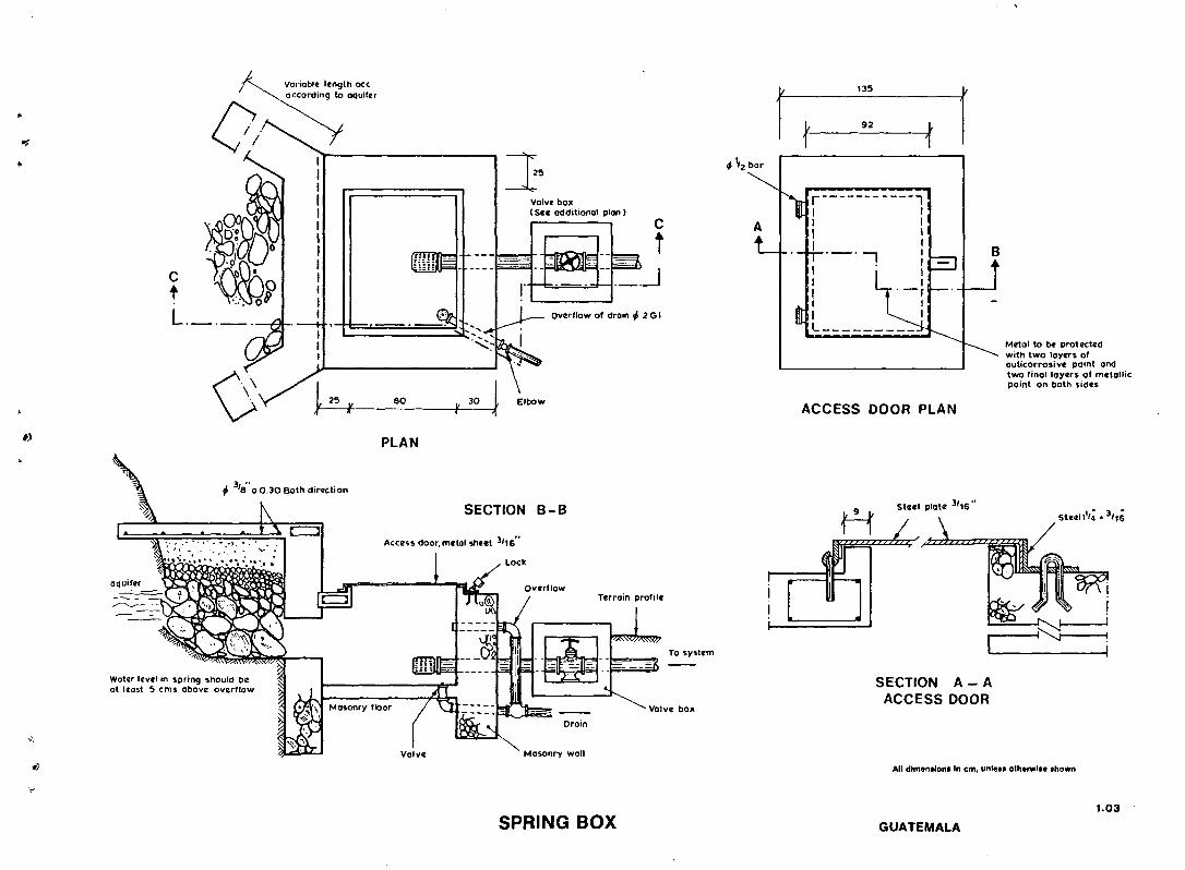
variable length ace according to aquifer
c t L._
PLAN
^ '8 o o 30 Both direction
SECTION B-B
Access door, metal sheet 3 '16
Lock
Terrain profile
To system
Water level in spring should be ^ at least 5 cms above overflow >>
Valve box
Valve Mosonry wall
bar
v 1 * i ! t_.._iL.._._,
1 i I l 1 I 1 h r - r
1
r i
1
-1
—•
co
Metal to be protected with two layers o( auticorrosive paint and two final layers of metallic paint on both sides
ACCESS DOOR PLAN
Steel plate 3 /16
H . / . A yjiuij ilfiii ' 11 >>i m i l l
Steel I'M . 3 / ) |
SECTION A - A ACCESS DOOR
All dimensions In cm, unless otherwise shown
SPRING BOX GUATEMALA 1.03

' >
t*4-
B /
t,._/_ Intake Chamber
•<&rr-=FtT
/ " / " i * Spillway boards
Supply pipa
Clcon out
L«vel up to the bonk
PLAN
t\\<" *'°>V " *
t^f 55 , » , « t
SECTION B-B
OUTLET
Strainer (see detoil on drawing no. )
Bfffi1 , *y# G.I . Flange f i " or 5 0 m m
G.I. P l p e y 2 " LtBOcn
Flange s e t / T 2 " - 6 3 m m
G I.Nipple jf 2" or 5 0 m m
Gate valve jT2"or SOmm
CLEAN OUT _ m M n l 1 _G.I.EIbow -^"2"or50mm
G.I Pip*jf£"or 50mm L«60cmT T
Gate valve jfi" or 5 0 mm |
G I N l p p l a y 2 " o r 5 0 m m
G. I .P Ipey"2"or50mm L « 5 0 c m
All dimensions In cm, unless otherwise shown
SMALL STREAM CATCHMENT INTAKE WITH LOW DAM

Scale A mg C I / 1
0 0 9 0 9 0
7,0
6 0 —
5 0 ——
Scale B g C a h y p o c h l o r i t e ( 7 0 % )
1 0 -
0.9 •
O B -
0 7-
0 6 -
0 5 -
0 4 -
1 0 0 0.0 eo-o.o
° 4 0 0 0
' t 0 0 . 0
eo o
oO.O
" 2 5 . 0
15 .0
5.0
0.9 =
_
= 9 0 0 0 700 0
5 0 0 0
300 O
150 0
9 0 0 70 0
5 0 0
30 0
20 0
1 0.0 8 0 6 0
1 0
o a
Scale C I Solut ion
• 1 0 0 0 0 0 • 9 0 O O 0
8 0 0 0 0
• 7 0 0 0 0 ' 6 0 0 0 0
50OO0
a _ 4 0 0 0 0
• 3 0 0 0 0
2 0 0 0 0
15 0 0 0
1 0 0 0 0 9 0 0 0 8 0 0 0 7OO0 6OO0 5 0 0 0 4 0 0 0
3 000
2 5 0 0
2 0 00
I Piattic cop Plastic jtrrycon
To clean water tank To citon wot«r tank
DOSING OF 70% HYPOCHLORITE
All dimtntlom In cm. unlen otrwrwlM thown
PLASTIC JERRYCAN CHLORINATOR

1127.5
D
1 D D
]
1 TRTi
D
150 mm # ventilator
ELEVATION
Platform cement cone. 1 :2 :4 mix.
Y 5 0 0 mm wide iron ladder -
1 0 0 mm f rain water pipe
100 mm 4 over flow pipe
75 mm • scour pipe-.
Roof ventilator 150 mm 0
Brick masonry 1: 3
Mortar
RC slab 1:2:4 mix. 75 mm thick, slope 1:40
DETAILS OF VENTILATOR A.B.C.
Fly mesh
Wooden frame
112 mm RC. core wall
f A
Brick masonry -
PLAN Ventilator A B C . 45 x 6 0 with wooden frame having fly mesh.
Flat iron supports
125 mm. # outlet pipe
100 mm. # inlet pipe
75 mm. # scour pipe
100 mm RC. 1:1*5:3 mix
0 0 0 mm • manhole
M.S. foot - steps
Brick on edge over 75 mm thick cone. 1 :4:8 mix
100 mm # over flow pipe
80 mm thick cement concrete brick
platform 30 x 30
100 mm # rain water pipe
^ 100 mm * inlet pipe
125 mm * outlet pipe
Brick on edge over 75 mm cone. 1:4:0 mix.
PLAN ON A - A
NOTE : For Dimensions of 14 m 3 Capacity Tank See Guide Notes
Door
PLAN ON B - B
-112 mm brick masonry 1:3 mortar inside and out side
- 5 0 0 mm wide iron ladder
» 20 mm f> M.S. rungs 300 o.c.
f v.4:oi mix. v.
iTNl i" 1 1 " 1
0*90 x 2 * 0 2 5 m L J
40 x 40 x 5 mm angle iron ladder
- 4 0 x 4 0 x 5 m m angle iron support bracket
• Cone. 1 : 4 : 8
All dimensions In cm, unlets otherwise shown
4.11
ELEVATED SERVICE RESERVOIR 65 m3 CAPACITY WHO/SEARO

150
4 6 mm elongated holes
4 3 0 m m Hole 40
Mild steel bolt 4 4 m m for stroke adjustment
Mild steel bolt 4 6 mm, long 90 mm
Valve spring
ALTERNATIVE DESIGN OF IMPULSE VALVE
Valve weights -
K 3o r° \
n r t Thin walled metal tube 10 mm bore 6 0 mm long
/ M
uinfchfr 4 AC\ m m *— A 4 50 mm pipe connector
Rubber washer f 40 mm
Steel washer
Mild steel bolt 4 4 mm for spring tension
r z z z z z z r ^ H \ZZZIZa^mrrrrrTTt^ZZXZI3\ a S I M P L E C L A C K VALVE b FLEXIBLE RUBBER
, _ n _ . WASHER
-—=r—Weight*
ASSEMBLY OF IMPULSE VALVE STEM & SPRING TENSION BOLT
4 5 0 mm mole thrcatcd
v hippie
Pin moves in and out with each squirt of water Keeping~--^ holes clean
DETAIL A
Valve plate
i^K>xa I
WELDING CONNECTOR TO PLATE
i-\?
' U ' Bend in spring
SPRING-BENT TO SHAPE FOR IMPULSE VALVE
4 6 mm
z 4 0 mm
•^r
\J—l-t
20 100 2S0 30 20 ^ 6 5 0 « 3 0 x 2 mm M.S. Strip
tin
M.S. SPRING STRIP All dimensions m cm, unlets otherwise shown
Valve can be unscrewed and replaced
I 50 mm . Perforated L valve plate
Valve prate
f) 4 mm Bolt
SECTION A-A Direction of flow
CLACK VALVE IN GUIDE
HYDRAULIC RAM: COMPONENTS 6.10
WHO/SEARO

600 x 6 0 0 mm M.H. opening
^ 75 mm Overf low pipe
5 0 0 x 500 m m -Squore concrete splash block
Concentr ic steel (410 mm 2 0 0 m m o.c . I rom 160 radius t o edge
All dimensions In cm. unless otherwise shown
CLEAR WATER STORAGE RESERVOIR WITH DOMEROOF WHO/SEARO
4.12

/
k,
10 15
. Detail I
60
f f 6 0 IS 49
I—iHH
230 10 5 0 10 1 7 8
4^d
N.P. r
" J '•', 60
H4—f-60 1 5 4 S
-*—H4 Ventilation pipe
Masonry wall -5 i n — i
TANK COVER MAN HOLE
Slob
^ I s
DETAIL I
All dimensions In cm, unless otherwise shown
MASONRY DISTRIBUTION TANK 20 m^ 6.07
MEXICO

HAND PUMP UNIT FOR PUBLIC USE CAPACITY 1000 LITRES/HOUR
Perforated precoit slab 50 mm. thick 3 pieces, with omm. # hol«i 60 mm o.c. { removable)
Ventilator of 50 mm die" G.I. pip* with bras* mesh -
HAND PUMP UNIT (DOMESTIC USE ) CAPACITY 200 LITRES/HOUR
25mm. sit* lime stone/ferro manganous or« & cok« 150 mm. deep
M.S. Rod grating of 10 mm. M.S. Rod* 2 5 mm. O.C.
25 mm. F* ventilator hole* 12 not.
540 Coarse sand 300 mm. thick lay«r ""effective size 0'7 mm
PV.C./G.I. Laterals 25 mm. # 100 mm. O.C. with 3mm * hole* 50 mm. O.C
Clean out pipe 50 mm . # All dimensions in cm, unless otherwise shown
PLAN Drain to natural droinoge or soakoge pit
HAND PUMP WITH IRON REMOVAL UNIT 4.01
WHO/SEARO

Hand pump
y ' 4
".**$
4
4
t It-
Conic notes
All dimensions In cm. unless otherwise shown
LONGITUDINAL SECTION DOG WELL
DUG WELL
PLAN WELL COVER
PERU 1.01