Type DAS 72.1 Process Indicator - Flintec · PDF fileProcess Indicator Type DAS 72.1 Mark III...
3
RoHS compliant IP40 weighing indicators | DAS-72.1 | www.flintec.com E106-Rev7-GB das-72.1-e-wi-dat-en-1.0.0 DAS-72.1 process indicator product description The DAS 72.1 Mark III process indicator is a fast, accurate, rail mounting instrument for static and dynamic weighing applications. It has a 5-digit LED weight display and service display, serial interface, analogue output and 3 digital inputs and outputs. The digital inputs and outputs are programmable. Communication via serial interface RS422/RS485 makes it easy to connect to PC, PLC and other devices. Standard weighing functions are available. Display of: Gross Weight; Net Weight; Peak Value; Peak to Peak Value; Average Value; Hold Value; Valley Value. Software calibration and set up. Basic version: Printed circuit board with metal housing for DIN-rail mounting; with screw terminals applications Universal process weighing systems and process automation & control applications. options Communicator RS485/Profibus (external) accessories Setup software running under MS Windows key features Internal resolution ±260,000 counts Conversion rate max. 2,400/s Non-volatile tare on/off Display control by logic input Digital filter, programmable Calibration with weight or in mV/V Linearity better than 0.002% 6 Wire load cell connection 3 Logic inputs (opto-isolated) 3 Logic outputs (opto-isolated) Network function by RS422/RS485 Analogue output 0/4 ... 20mA Power supply 11 ... 25VDC
Transcript of Type DAS 72.1 Process Indicator - Flintec · PDF fileProcess Indicator Type DAS 72.1 Mark III...

RoHScompliant IP40
weighing indicators | DAS-72.1 | www.flintec.com E106-Rev7-GB das-72.1-e-wi-dat-en-1.0.0
DAS-72.1 process indicator
product description
The DAS 72.1 Mark III process indicator is a fast, accurate, rail mounting instrument for static and dynamic weighing applications.
It has a 5-digit LED weight display and service display, serial interface, analogue output and 3 digital inputs and outputs. The digital inputs and outputs are programmable. Communication via serial interface RS422/RS485 makes it easy to connect to PC, PLC and other devices.
Standard weighing functions are available. Display of: Gross Weight; Net Weight; Peak Value; Peak to Peak Value; Average Value; Hold Value; Valley Value. Software calibration and set up. Basic version: Printed circuit board with metal housing for DIN-rail mounting; with screw terminals
applicationsUniversal process weighing systems and process automation & control applications.
options
Communicator RS485/Profibus (external)
accessories
Setup software running under MS Windows
key features
Internal resolution ±260,000 counts
Conversion rate max. 2,400/s
Non-volatile tare on/off
Display control by logic input
Digital filter, programmable
Calibration with weight or in mV/V
Linearity better than 0.002%
6 Wire load cell connection
3 Logic inputs (opto-isolated)
3 Logic outputs (opto-isolated)
Network function by RS422/RS485
Analogue output 0/4 ... 20mA
Power supply 11 ... 25VDC
2weighing indicators | DAS-72.1 | www.flintec.com E106-Rev7-GB das-72.1-e-wi-dat-en-1.0.0
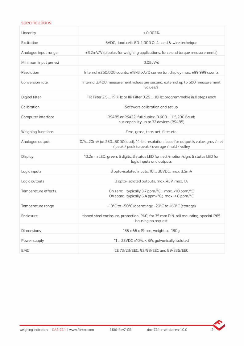
specifications
Linearity < 0.002%
Excitation 5VDC, load cells 80-2, 000 Ω, 4- and 6-wire technique
Analogue input range ±3.2mV/V (bipolar, for weighing applications, force and torque measurements)
Minimum input per vsi 0.05μV/d
Resolution Internal ±260 ,000 counts, ±18-Bit-A/D convertor; display max. ±99 ,999 counts
Conversion rate Internal 2,400 measurement values per second; external up to 600 measurement values/s
Digital filter FIR Filter 2.5 ... 19.7Hz or IIR Filter 0.25 ... 18Hz; programmable in 8 steps each
Calibration Software calibration and set up
Computer interface RS485 or RS422, full duplex, 9,600 ... 115 ,200 Baud; bus capability up to 32 devices (RS485)
Weighing functions Zero, gross, tare, net, filter etc.
Analogue output 0/4...20mA (at 250...500Ω load), 14-bit resolution; base for output is value: gros / net / peak / peak to peak / average / hold / valley
Display 10.2mm LED, green, 5 digits, 3 status LED for nett/motion/sign, 6 status LED for logic inputs and outputs
Logic inputs 3 opto-isolated inputs, 10 ... 30VDC, max. 3.5mA
Logic outputs 3 opto-isolated outputs, max. 45V, max. 1A
Temperature effects On zero: typically 3.7 ppm/°C ; max. <10 ppm/°C On span: typically 6.4 ppm/°C ; max. < 8 ppm/°C
Temperature range –10°C to +50°C (operating); –20°C to +60°C (storage)
Enclosure tinned steel enclosure, protection IP40; for 35 mm DIN-rail mounting; special IP65 housing on request
Dimensions 135 x 66 x 19mm, weight ca. 180g
Power supply 11 ... 25VDC ±10%, < 3W, galvanically isolated
EMC CE 73/23/EEC; 93/98/EEC and 89/336/EEC

3weighing indicators | DAS-72.1 | www.flintec.com E106-Rev7-GB das-72.1-e-wi-dat-en-1.0.0
Dimensions and specifications are subject to change without notice.
66
135
0
Net
Digital Amplifier + Setpoint DAS 72.1 Mark III
SET UPTTT0T
Inp.1 Inp.2
0T
Inp.1
TInp.2
1
2 3 4 5 6 7 8 9 10 11 12 13
14 27
15 16 17 18 19 20 21 22 23 24 25 26
Silo Nr.: 1
Netto : 17285 kg
Tara : 1458 kg
+ + + + + + +
0-20mA
- - - - - 00
Exc Sen Inp Inp Sen Exc Rx Rx Tx Tx
Load cell 5Vdc 80mAIsolated
Logic OutputsIsolated
Logic InputsIsolated
Power 11 -25VdcRS422/485CL out
1.Zero1.0/allow>0<2.Calibrate3.Set mV/V
2.Span1.Set cal. ´n´2.Calibrate3.Set mV/V4.Disp.mV/V
3.Display1.o/u limits´n´2.Step * ´n´3.Dec.point4.Logic stats
4.Filter1.f Hz2.Algorithm3.Update rate4.Motion´n´
cut
5.CLout1.4mA=´n´2.20mA=´n´3.Base4.Test I mA
6.Input 1/2/31.Assign key2.3.4.Test
7.Outp. 1/2/31.SPoint ´n´2.Hyst. ´n´3.Base4.Test
±
8.Datacom.1.Baud rate2.422/4853.Address4.Auto trnsm.
1 2 3 com 1 2 3 com
Io Gnd
Logic input 1 2 3
1 2 3Logic output
Depress
To
Change
Power supply
11 - 25 V DC
(galvanically isolated)
3 digital outputs
(optoisolated,
max.
45V AC/DC /1A)
Load cells;
6-wire
connection
RS422/485
interface for
PLC/PC connection
or remote display
3 logic inputs
(optoisolated,
10...30 V DC)
Analogue output
0/4 - 20 mA
for
PLC/PC connection
system configuration