TYPE DA AIR CIRCUIT BREAKER - Electrical Part Manual S · TYPE DA AIR CIRCUIT BREAKER 1'" } rl...
56
TYPE DA AIR CIRCUIT BREAKER 1 } r l Frontispiece Type DA 50, Three-Pole Air Cuit Breer Westinghouse Electric Corporation East Pittsburgh, Pa. Print in U.S.A. (Rep. 11.52) LB. 59+ A FUing No.35-2 www . ElectricalPartManuals . com
Transcript of TYPE DA AIR CIRCUIT BREAKER - Electrical Part Manual S · TYPE DA AIR CIRCUIT BREAKER 1'" } rl...

TYPE DA AIR CIRCUIT BREAKER
1'"
}rl
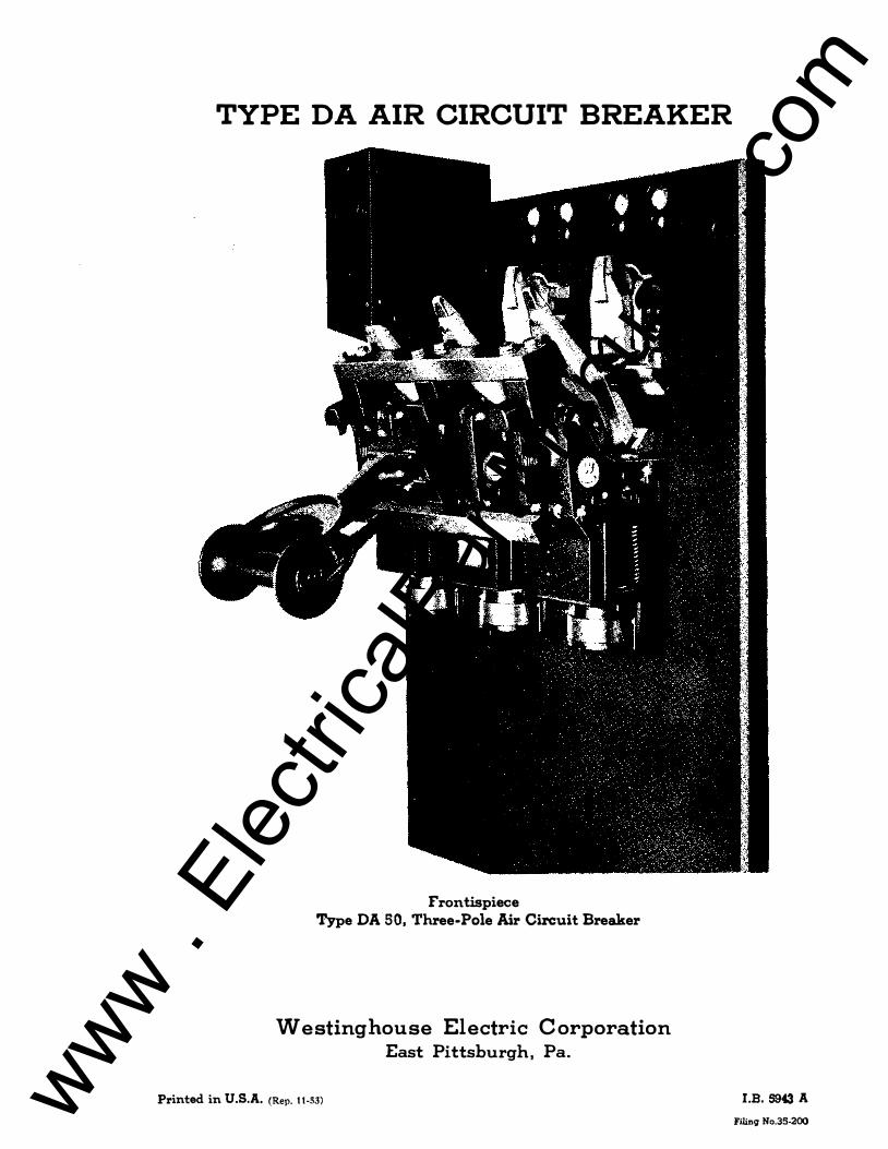
Frontispiece Type DA 50, Three-Pole Air Circuit Breaker
Westinghouse Electric Corporation East Pittsburgh, Pa.
Printed in U.S.A. (Rep. 11.52) LB. 5943 A FUing No.35-200 www .
Elec
tricalP
artM
anua
ls . c
om

PR EF AC E
It would be difficult to over-emphasize the importance of adequate care of all protective devices. To assure proper functioning, they should be the subject of periodtcal, systematic and intelligent inspection. Even the smallest details of required maintenance should not be neglected if costly failures of equipment and service are to be avoided. Maintenance must include occasional checks on calibration as well as on the coordination and freedom of all moving parts. The purpose of this Instruction Book on the DA circuit breakers is to provide a guide for those charged with these responsibilities. It is not possible to outline a procedure that will apply in all cases. The frequency and character of inspection will for the most part be a matter of experience. In general, light monthly inspection, with a thorough inspection semiannually, should be a mlnlmum. The Company will be glad to furnish. such additional information as may be needed to amplify or clarify these instructions.
www . El
ectric
alPar
tMan
uals
. com

INDEX
Description
Protection From Dust • •
Unpacking. • • • • • •
Lubrication. • • • • • • • • •
Installation • . • • • • • • •
Adjustment of Main Contacts. Adjustment of Contact Arm. • .
Adjustment of Contact Sequence Adjustment of Arc Chamber. . .
· .. . ., . . . .,
· ., - . ., . . . · , ., . . . . . · . . . . . .
· · · · · ·
• · • · · · •
· • · · • · · • ·
• · · · · · • · ·
· . . · .
· . . . .
· · ·
• · · · ·
· • · • ·
· · · · ·
Adjustment of the Trip Bar Assembly • •
Adjustment of Auxiliary Switch • • •
Adjustment of Field Discharge Switch . Adjustment of Closing Linkage. • • • •
· ., . . . ., . . . . · . . . . . .
• • • • • • *' .,
· . . . . . . . . .
Adjustment of the Closing Magnet Cut-Off Switch. • • • • •
Control Schemes. • • • • • • • • • • • • • • • • • • • • •
Suggestions for Locating Cause of Improper Operation • • •
Suggestions on Removal of Parts • • • • • • • • • • • • • •
Series Overload Trtp Attachments • • • • • • • • • • •
Non-Adjustable Short-Circuit Trip Attachment •
Instantaneous Trip AttaclLment • • • • • • • • • • · . .
Inverse Time Limit Attachment. • • • • • • • • • • • •
Shunt Trip Attachment • • • • • •
Undervoltage Trip Attachment • •
Reverse Current Trip Attachment.
i
· . . . . . . ., · . . · . . . . . . . . . . . .
· . . . . . . . . . .
Page
1 1 1 1
2 2 2 3
3 3 3 4
4 4 5 6
8 8 9 9
10 10 11
www . El
ectric
alPar
tMan
uals
. com

Frontispiece
Figure 1
Figure 2
Figure 3
Fi.gure 4
Figure 5
Figure 6
Figure 7
Figure 8
Figure 9 Figure 10
Figures 11,12,13
Figure 14
LIST OF ILLUSTRATIONS
- DA-50 Three Pole Air Circuit Breaker
- DA-50 Pole Unit
- DA-75 Pole Unit
- DA-100 Pole Unit
- Auxiliary Switch
- 3-inch Closing Magnet
- Field Discharge Switch
- Instantaneous Trip Attachment
- Characteristic Curves - Inverse Time Limit Device
- Undervo1tage Trip Attachment
- Inverse Time Limit Overload Attachment
- Dia.gram Inf ormat i on-Breaker Control Schemes
- Reverse Current Trip Attachment
- ii -
www . El
ectric
alPar
tMan
uals
. com

TYPE flDA" AIR C IRCUIT BREAKER
PROTECT ION FROM DUST
1. Excessive deposits of dust and dirt in the operating parts of a circuit breaker invariably cause binding of shafts, triggers, rollers and pins as well as the operating levers. Care should be taken, therefore, to see that accumulation of dirt is prevented and this is particularly true in new installations where the circuit breakers have been installed before the building construction work has been completed. In the latter case the breakers should be completely covered by a tarpaulin to prevent plaster and like material from falling on them.
UNPACK ING
2. Care should be used in uncrating so that no parts are damaged or broken. All dirt which may have collected on the breakers should be removed. Wipe contact surfaces with a cloth or waste to remove grease used to protect contacts during shipment. A careful inspection should be made to make sure that none of the parts have been damaged in transit.
LUBRICATION
3. Lubrication of the various parts of the mechanism as applied at the factory should be sufficient for years of service. It should be remembered that oily surfaces promote the accumulation of dirt and for that reason contact surfaces should be kept free from oil or grease. (Refer to paragraph 2). Therefore, it is recommended that no lubricants be applied to the breaker mechanism.
INSTALLATION
4. It is preferable that air circuit breakers b e shipped on permanent bases instead of temporary bases to eliminate the additional labor and the possibility of misalignment and improper adjustment.
5. In those cases where remounting is necessary, care should be taken to avoid dismantling furthf'r than necessary and thus pl"eserve the adjustments and avoid incorrect assembly.
6. Each pole unit retains shaft alignment independently on the panel due to the one-piece construction of the frame ( see Fig. 1, 2 and 3). However, when mounting multipole breakers, care must be taken so as to align the frames with respect to each other so that the common crossbar and trip bar operate freely. This alignment may be obtained by inserting a round steel bar of suitable diameter and length simultaneously through the holes of all frames from which the main fulcrum pins have been removed. Before tightening the frame mounting bolts, check the location of the frames of outer poles with respect to hoI es :tn the panel which receive the arc tip springs.
- 1 -
www . El
ectric
alPar
tMan
uals
. com

7. It is important that connecting bus be or surficient cur-rent carrying capacity and that connections to the breaker be properly jOined. Obviously heat conducted into a breaker rrom a hot joint will increase the temperature rise or the breaker.
8. Connecting cables or bus should be well supported and braced so that the breal{er studs will not be subjected to unneces-3ary strain as a result of magnetic forces set up by short circuit currents.
ADJUSTMENT OF r�IN CONTACTS
9. Inherent to their design the main contact bridging members are self-aligning to a considerable degree provided stationary contact surfaces and the breaker rrame are assembled properly, as described above.
10. Pressure between the silver contact surraces is obtained by a compression spring which requires no adjustment other than that given to the complete contact arm assembly.
ADJTJSTMENT OF CONTACT ARM
11. To adjust the contact arm the completely assembled breaker should be placed in a partially closed position. After the bolt which clamps the eccentric pin is loosened the eccentric pin should be turned to a position which brings the inside surface of the contact arm parallel to the panel when the breaker is in the closed position. The dimension between this machined surrace and the panel which makes them parallel on each rrame size are shown in rigures 1, 2 and 3. Ir the breaker has more than one pole, partially close the breaker to the point where at least one set of arcing contacts touch, then reset the eccentric pins or each pole to cause the arcing contacts or all poles to "make" at the same time by moving one arm closer to the panel and one arm away from the panel. Care should be taken to securely locl{ the eccentric pin again berore operating the breaker. Berore this adjustment should be considered complete, inspection should be made to make sure that all rloating contact members remain free. This check is readily made by prying each set or contacts gently apart with the aid or a 1.arge screw driver or similar tool, being carerul not to mar the contact surraces.
ADJUSTIIlENT OF CONTACT SEQUENCE
12. IT IS VERY IMPORTANT THAT ADEQUATE SEPARNrrON IS OB'rAINED BETWEEN MAIN CONTACT SURFACES AT THE TIME THE SECONDARY CONTACTS SEPARATE DURING THE OPENING STROKE OF THE BREAKER. This separation should be approximately S/321! for the DA-SO, 3/1611 for the DA-7S., and 3/16" ror the DA-100.
13. This separation can be obtained by first adjusting the contact arm., as per paragraph 11, then adjusting the nut located at the center or the bridging members. To adjust the nut, remove the locking pin and screw down the nut to a point w;'lere it; just touches the bridge member with the brealcer in the closed position, then
- :2 -
www . El
ectric
alPar
tMan
uals
. com

back off the nut 1/1611 and lock in position with the locking pin. (Note:- 1/16ff corresponds to one turn of the nut on DA-50 and DA-75 breaker and to 5/6 of a turn cn the DA-IOO breaker).
14. It should be borne in mind that satisfactory performance of the breaker depends upon maintaining this important adjustment. It is obvious that after this adjustment is made the eccentric pin setting should not be changed as the adjustment will be lost.
ADJUS�lENT OF ARC CHAMBER
15. Proper alignment of the arc chamber is obtained when the machined surfaces at the rear of the assembly are resting on the spring guard of the breaker pole assembly. The anchor bolts rest in clearance holes in the panel and when loosened may be shifted about to accommodate this adjustment. Once the proper alignment of arc chamber and the breaker poll" has been obtained and anchor bolts tightened, the chamber may be subsequently removed by unscrewing the mounting bolts from the front of the arc chamber.
ADJUSTMENT OF THE TRIP BAR ASSEMBLY
16. The trip bar assembly consists of the trip lever of each pole unit, a connecting bar of insulating material and trip knob or bracket to which tripping force may be applied. In order that triggers may respond promptly to tripping forces initiated by overload or shunt tripping devices, it is imperative that the trip bar assembly be as frictionless as possible. Best results are obtained on m1.<ltipole assemblies when the trip bar is adjusted to provide a maximum of end-play at the bearings.
ADJUSTMENT OF AUXILIARY SWITCH
17. Rotary type auxiliary switches are sturdily constructed and provide a variety of combinations of opening and closing contacts. Positive operation is obtained through an adjustable operating link which connects the rotor cranlc to the breaker. Proper setting of the auxiliary switch is obtained by adjusting the length of the rotor cranl{ and' the length of the operatin&,� link so that the rotor crank pin is at a point 450 below the horizontal when the breaker is closed and at a point 450 above the horizontal when the breaker 1s in the extreme open position.
18. For normal application the assembled relation between crank and rotor causes the contact segment nearest the crank to close when the breaker closes.
ADJUSTI�ENT OF FIELD DISCHARGE SWITCH
19. When properly adjusted the contacts of the Field Dis-charge Switch close before the arcing contacts of the breaker separate during the opening stroke, and open before the breaker contacts touch during the closing stroke. Figure 6 shows the approximate position of the Field Discharge Switch at various positions of the breaker contact arm.
- 3 -
www . El
ectric
alPar
tMan
uals
. com

20. Adjustment of the position of the switch arm with respect to the breaker contact a.rm is obtained by varying the length of the operating link by means of the threaded jOint.
ADJUSTMENT OF CLOSING LINKAGE
21. To obtain the maximum closing effort from any particular closing magnet, the alr gap between the moving and stationary core sections should be as short as practicable at the point in the closing stroke where the force requirement is greatest. The ideal adjustment, therefore, is obtained when the closing linkage is adjusted to provide only the necessary over-travel of the latching roller at the position where the magnet cores come together. An overtravel of 1/32" to 3/32" at the latching roller is recormnended which corresponds to an angular' movement of 0.5 to 1.5 degrees in the closing lever of the DA-50, 0.4 to 1.3 degrees movement in the DA-75, or 0.3 to 1.0 degree movement in the DA-IOO. Attempts to adjust for an abnormal amount of over-travel may cause the stops in the breaker mechanism to meet before the magnet cores meet and thereby needlessly cause high stress in the breaker parts.
22. Adjustment of the length of the closing linkage is pro-vided by means of shims in the smaller breaker assemblies and by a threaded joint in the closing link of larger assemblies. Variations in length equal to the thickness of shims may be obtained by loosening the bolted joint and removing or adding shims. In assemblies provided with a threaded joint, variations equal to onehalf of the thread pitch may be obtained by removing the pin at the lower end of the link. When loosening the jOints, precaution should be taken to prevent the moving core from escaping upward under the action of the retrieving spring, which is enolosed in the core structure.
ADJUSTMENT OF THE CLOSING MAGNET CUT-OFF SWITCH
23. Closing coils are designed to remain energized only momen-tarily, hence to avoid overheating them provision must be made to interrupt the closing coil circuit immediately after the breaker has latched closed. Unless otherwise specified, a small "Cutoff" switch having contacts which "make" as the cores of the closing magnet come together is mounted on the closing magnet.
24. Proper adjustment of the cut-off switch requires that its contacts be closed and remain closed when the moving core reaches the end of its closing stroke. Due to the inertia of the moving part s of the brealcer, mov ing Core and con tac tor, it is prac tical to permit the cut-off switch contacts to touch slightly before the core reaches the end of the stroke�
CONTROL SCHEMES
25. Typical control schemes employing a cut-off switch are shown by figures 11, 12 and 13. It will be noted that, \-There one of these schemes is used, automatic reciprocation of the closing mechanism (known as pumping) cannot occur in the event the cutoff SWitch or breaker mechanism should lose its adjustment.
- 4 -
www . El
ectric
alPar
tMan
uals
. com

26. With the s cheme shown as figure 11, the cut-off sWit ch i s us ed to energiz e the r eleas e c o i l of the type IiS_l l l re lay which p ermi t s its c ontacts t o open. Contac t s of the "S_11! r elay cannot be clos ed again t o re-energiz e the clos ing coil circuit unt i l the op erat ing c oil c ir cuit of thi s relay has been opened t o permit its armatul'e to r e s et with the c ontact arm. Therefore, a s ingle c los ing operat i on of the c ontro l sWitch c ontac t s will cau s e but a s ingl e clos ing operat i on of the breaker c los ing me chanism.
27. With the schemes shown a s figur e 12 and 13 , the cut-off switch i s u s ed to energize a cut-off (Y) relay whi ch in turn opens the operat ing c oil c ircuit of the contact or (X), caus ing the con tacts "Xfl t o open the c lo s ing c oil c ircuit, The "y" r elay remains energized unt i l the control swit ch c ontact is opened and by this means Hpumping" is avo ided,
SUGGESTIONS FOR LOCATING CAUSE OF IMPROPER OPERATION
28. Fai lure t o Trip F rom Overload May Be Due To:
a. Improper s etting of current calibrat i on.
b. Friction in tr ipping details as a result of for eign ob j ects or a br oken part.
c. Stray-magnet i c fields.
29. Fai lure T o Trip By Remote Control May Be Due To:
a. Open c ircuit due to loose c onnect ion.
b. Burned out trip c oil.
30. Ov erheat ing of The Breaker May Be Due T o:
a. Overload.
b. Improper ad justment of spring pres sur e on main c ontacts. ( Refer to adjustment of contact arm and c ontact s equenc e.
c. Poor condit ion of main c ontact surfac es.
3 1. Exc e s s Burning of Main C ontac t s May Be Due To:
a. Poor c ontact at the s e c ondary c ontact s due t o an ob struc t i on , surface c ondi t i on or inadequat e spring pres sure.
b. High reSis tance of the s e c ondary contact c ir cuit due t o loose j oint a t the upper o r lower shunt.
c. Inadequat e lead of main c ontact ov er s e c ondary c ont act. ( See ad justment of c ontact s equenc e.)
32. Failure Of The Brealcer To Lat ch-In When Closed May Be Due T o:
a. Inadequat e overtrave1 of la'l";ch r oller beyond the latched position. Thi s may b e due to exc e s s ive length of clos ine linlcage, which permi t s the cor e s of the c lo s ing magnet
- 5 -www . El
ectric
alPar
tMan
uals
. com

to make contact before the latching pawl has room to move in behind the roller. For recommended overtravel, refer to paragraph 21-
b. Failure of the latching pawl to retrieve after the roller passes due to excessive friction or due to a damaged pawl spring.
c. Excessive rate of closing which in turn may be due to abnormal voltage on the closing coil or inadequate compression of air in the closing magnet. A greater cushioning effect can be obtained by reducing the size of the exhaust vent located at the lower end of the closing magnet. It should be remembered that the size of the exhaust vent also affects the speed at which the closing link retrieves.
33. Failure Of Latching Roller To Retrieve Behind The Tripping Latch When The Breaker Is Tripped May Due To:
a. Excessive friction between piston and cylinder of closing magnet. This may result from the accumulation of dirt or solidified lubricant. Under ordinary operating conditions no lubricant is required.
b. Inadequate retrieving force resulting from a damaged retrieving spring which is located inside the closing magnet assembly.
c. Excessive friction or interference which prevents the latch from receding from the path of the latching roller.
SUGGESTIONS ON REMOVAL OF PARTS
34. Occasionally it is desired to remove parts of the break-er for inspection or to make replacements and the following instructions may be helpful:
a. To remove the contact arm: Remove the pin which connects the toggle link to the contact arm. Discormect the opening springs from the main frame but leave them connected to the contact arm. With the aid a long screl" driver remove the screws which clamp the flexible shunt to the lower current stud. On the ching pole it is sometimes desirable to remove the trip lever to make the shunt mounting bolts more accessible. By reInoval of the contact arm hinge pin the complete arm assembly may then be lifted out of the breaker.
b. To remove the moving arcing contact: The three tap bolts should be removed from the back of the moving contact support. These bolts are made of non-magnetic material and substitution by steel bolts should be avoided.
- 6 -
www . El
ectric
alPar
tMan
uals
. com

c. To remove the stationary arc1�g con�act: Open the breaker and remove the arc chamber. From the rear of the panel, remove the two 1/4" tap bolts 'Which support the arc tip spring plate. Precautions should be taken to avoid injury when releasing the energy in the partially compressed spring by holding the spring compressed with the aid of a short beam of wood or similar object until both bolts are completely removed. Remove the remaining tap bolt and flat head screw from either one of the stop brackets which permits the removal of the stop bracket and the guide pin. By tilting the lower edge of the contact platform away from the panel the secondary contact springs and insulating washers may be removed. With a screw driver perform the final operation of removing the bolts which hold the enclosed shunt from the upper current stud.
d. To remove the coil from the closing magnet: Remove the cover from the front of the assembly. Remove the side plates leaving the auxiliary switch and the wiring to it intact. Disconnect wires from the clOSing coil and from the cut-off switch. With the breaker in the tripped pOSition provide temporary levers or other means to restrain the moving core as it is being expelled by the enclosed retrieving spring, before disconnecting the closing linkage between it and the breaker mechanism. Disconnect the clOSing linkage and by absorbing the energy from the enclosed spring through the temporary restraining means, allow the moving core to be slowly expelled. The stationary core-section and cylinder wall can be removed as a unit from the bottom of the magnet assembly by removing the bolts in the outer bolt circle. After the magnet core is removed, the coil is removable from the front.
e. To remove the oil pot of the Inverse-time-1imit on the DA-50 breaker:
(1)
(2)
(4)
Loosen both knobs on the overload dash pot.
Place both knobs straight to the left hand side of the breaker facing panel.
Turn both knobs in unison to the extr.eme right, look ing at the bottom of the oil pot, and continue the lower knob to the right until it is near the panel.
Then, holding the lower knob near the panel, turn the upper knob to left until the two knobs are 1800 apart.
Pull the lower portion, onto which the lower knob is attached, downward approximately 1/4".
- 7 -
www . El
ectric
alPar
tMan
uals
. com

(6) Turn the upper Imob to extreme right as far as possible and then turn the lower knob to the left until it is directly beneath the upper knob.
(7) Remove the lower oil pot by pulling straight downward.
(8) To replace the dashpot it is merely necess ary to reverse the above procedure.
SERIES OVERLOAD TRIP ATTACHMENTS
35. Series overload trip attachments are used to trip the circuit breaker whenever the current through the breaker exceeds a predetermined value. All forms of this device include a conductor of one or more turns connected in s eries with the breaker contacts , a s tationary magnetic circuit, and a movable iron armature. The armature is mounted in such a �ay that as it moves under magnetic attraction to reduce the air gap, it provides the force to trip the breaker latch. The amount of current required to s tart the armature is a function of air gap length and upon this principle all overload trips for DA breakers are calibrated.
36. The tripping magnet is us ed at its best efficiency when adjusted s o that, of the total travel of the armature, that part used to move the breaker trigger s hould be just enough to trip the trigger free of the latch lever. With this adjustment the maximum amount of armature travel is used to obtain momentum for tripping the breaker.
37. Each overload trip unit is calibrated on the breaker pole at the factory. Therefore, care should be taken not to interchange trip details with other breaker poles .
38. Powerful s tray magnetic fields do affect the calibration points to s ome extent on the larger breakers . \fhere the bus arrangement of the switchboard is known, the breakers are calibrated at the factory with the same arrangement.
39. All the overload trip devices reset thems elves auto-matically. That is , after tripping, they automatically return to their original pos ition.
40. Three clas ses of series overload trips are used to pro-vide the characteristics reruired for ordinary applications . These trips may be class ified as 1) Non-adjus table Short-circuit trips , (:2) Ins tantaneous trip and 3) Invers e Time Limit Trip Attachment.
NON-ADJUSTABLE SHORT - CIRCUIT TRIP ATTACHMENT
41. For a general description of s eries overload trip attach-ments , refer to paragraphs 35 to 39.
42. Short-circuit trip attachments are des igned to trip in-s tantaneously at s ome relatively high current value. The trip s etting is non-adjustable after being s et at the factory. Normally the tri.p s etting bears the follo�ing relation to the breaker l'ating:
- 8 -www . El
ectric
alPar
tMan
uals
. com

Breaker Rat ing ( 300C.) in Amperes-
up t o 600 800 t o 2000 2500 to 6000 8000 and above
INSTANTANEOUS TRIP ATTACHMENT
Trip Set ting in Amperes
9000 + 10% 15 t ime s bkr. rat ing + 10% 12 t ime s bkr. rat ing ± 10% 75, 000 .± 10%
43. For a general descript ion of s eries ov erload trips, ref er t o paragraphs 35 to 39.
44. Instantaneous trip attachment s ( s e e Fig. 7) are des igned to be cal ibrated on currents clo s e to the breaker rating. The standard range of calibrat ion is 100% to 200% of the normal 300C. rat ing of the breaker. Unless otherwi s e specif ied, the five main pOints, 100%, 125%, 150%, 175% and 200% are stamped on the s cale plate.
INVERSE T IME LIMIT ATTACHMENT
45. For a general description of s eries ov erload trip attach-ment s, ref er t o paragraphs 35 to 39.
46. The Invers e-t ime-limit attachment ( Se e Fig. 10) cons i s t s of a tripping device with the addit ion of a t ime delay device which prevent s tripp ing on relat ivel.y smal.l overloads which las t but a short t ime.
47. The time delay f eature is obtained by the sucker act ion b etween a smooth surfaced metal disc which is at tached t o the overload armature and which normally res t s on the smooth bot tom surface of a pot cont aining a small quant ity of oil ( approximat e ly 1/8 " deep) . The result ing sucker act ion retard s the start ing of the overload armature, the t ime of de lay be ing approximat ely inverse t o the magnitude of the overload. For characteristic curves, see Fig. 8.
48. A limited variat ion in the time de lay can be obtaine d by turning the pot which vari e s the amount of surface in contact between the sucker and pot. Further variat ion can be obtained by us ing o i l s of different visco s it ies.
49. The ov erload trip device i s calibrat ed wi thout o i l in the pot. The calibrat i on range and scale markings for the standard Inv ers e-t ime -limit attachment is the same as f or the Ins tantaneous Trip Attachment. ( Refer to paragraph 44).
50. To insure reliab le performance of the t ime de lay device, it is important that oi l in the pot be kept clean. A s ingle part icle of dirt between the sucker surfaces may great ly reduce the t ime delay. To remove imp erfect ions in the sucker surface s due t o bruis ing or other causes, it is sugge sted that a l l high spots be removed with a scraper. A paper washer is placed between the sucker surfaces to protect them during shipment. Thi s washer should be removed when placing the breaker in serv ice and before o i l is placed in tho pot.
- 9 -www . El
ectric
alPar
tMan
uals
. com

51. For instructions on removing the oil pot of the DA-50 Breaker7 refer to paragraph 34-e.
SHUNT TRIP ATTACHMENT
52. The shunt trip attachment is des igned to trip the brea1::er "I-Then the trip coil is energized by an auxiliary circuit, thus providing for remote control and various interlocking arrangements. Shunt trip coils are designed to remain energized only momentarily, hence provision should be made to interrupt the shunt trip circuit immediately after the brealcer has been tripped. It is common practice to obtain this result by means of an auxiliary switch having contacts which open as the breaker opens.
mWERVOLTAGE TRIP ATTACHMENT
53. The Undervoltage Trip Attachment (See Flg. 9) is used as a means for tripping the breaker when voltage applied to its coil drops below a predetermined value. Having this characteristic the Under-voltage Trip Attachment is adaptable to control schemes where a positlve tripping means is desired in case of failure of control voltage. Energy for tripping the breaker is produced by a spring which must be reset mechanically through links attached to the breaker.
5L�. The important elements of this device function as follows: When energized at rated voltage7 Magnetic Porce holds the armature to the stationary core against the action of the stressed tripping spring. The stronger reset spring works in oppOSition to the tripping spring, but by means of the reset linkage the reset lever is rotated by the breaker, as it closes, to a position which clears the "drop-outO movement of the armature. If the applied vol.tage decre�ses to a value at which the magnetic attraction for the armature is less than the force exerted by the tripping spring, the armature !1drops outfl and the breaker is tripped by energy from the tripping spring.
For applications which require a time delay feature o prevent the breaker from being tripped by momentary dips in
applied voltage, an oil-sucker attac:b..:ment is provided as shown. For fUrther information concerning this Inverse-time-limit device, refer to paragraphs 46 to 50.
56. When adjustments are to be made on an under voltage trip attachment, it i2 suggested that they be made in the order given below.
To adjust the relation between the armature and the time delay attachment, partially back out the upper adjusting screw (item 7), and with coil de-energized and reset lever (item 36) held downward, hold sucl::er stem (item 53) down and adjust lovrer SCI'ew (item 6) to obtain an air gap of 1/16i! at the upper end of the armature. Next release reset lever and adjust upper screw (item 7) to remove contact between armature and the end of screw ( i tern 6).
- 10 -
.�.
www . El
ectric
alPar
tMan
uals
. com

58 . To ad just for drop-out at a � iven vol tage , first app ly rat ed v oltage and d epr e s s reset lever (by c l o s ing breaker i f pract i cal) then reduce v oltage t o the des ired drop-out value and ad just the s c r ew ( it em 16 ) t o the p o s it i on whi ch causes the armatur e t o drop out . For normal app licat i ons the device is adjus t ed to drop out at a v oltage of 40% t o 60% of the rat ed v oltage .
REVERSE CURRENT TRIP ATTACHMENT
59. The rever s e current trip attachment is us ed to trip the breaker when the direct i on of current flow through the breaker is rever s ed .
6 0 . The revers e current trip mechanism c ons i s t s of a stat-i onary magnet energi zed by a c oi l in s er i e s with the breaker c ontacts and a movable iron armature ene rgi zed by a shunt c o il as shown in Fig . 14 . In the attachment rated 800 to 1600 amperes the magnet i c c ircui t s are energi z ed in the rev ers e manner . In e ither arrangement the armatur e i s piv ot ed betwe en two pairs of pole s . When the s eries c o i l current is flow ing in the normal direc t i on the armature t ends to r otat e in one direction but 1s restrained by an adj ustable cam. When the s eries current rever ses the armature i s rotat ed in the opp osite direction and provides the for c e to trip the br eaker w ith which it is mounted. Aft er tripping the armat ure is returned to its original pos it i on by a reset t ing spring .
6 1. Tripping at predetermined values of revers e current is obtained by ad just ing the relat i on between the armature and the pole fac es by means of the cam. Standard calibrat i on point s are marked on the s cale p lat e for currents repres enting 5, 10 , 15, 20, and 25% of the br eaker rat ing.
62. To reset the attachment it is nec e s s ary only to open the shunt coil c ir cui t . This i s usually acc omplished by means of the breaker auxil iary switch.
- 1 1 -
www . El
ectric
alPar
tMan
uals
. com

www . El
ectric
alPar
tMan
uals
. com

�r --� I I
------4 L
,<:II . ( I \ I "---
At:!Just eccentric pin to obtain this dimension.
/ Lead in inches Main Secondar Arcing contact � H
Panel _ .... 1--_
Ij or 211:1 Secondary contact i
81 .730
l Series Coil
Back up one turn after nut has touched contact bridge and lock in this
position.
Eccentric
Figure 1 - DA-50 Pole Units
Arc Chamber
www . El
ectric
alPar
tMan
uals
. com

1-- --2 ,2 !: 1.. -----.; Apjust eccentric V. - 8 16 i pm to obtain this Dim. , i ._--7 -
, _. __ .-
I Contoctleod in inches Main Secondary!
Arcing Ttp J I , touchmg . __ 4 __ i rsecon(iary--:O;Ti
;::-, P+-l--l---
,touchms ___ . 16 0
� .r;!!�-14f O",nlng "
10 �/'i
·--1 I I
.==-==-==::::t. --t±-J
I V Ir/
_____ / I
I / / / I
Figure 2 - DA-75 Pole Unit
I I i I Arc Ghamber
V I
www . El
ectric
alPar
tMan
uals
. com

I----rnf--�-__+_-+�t:l)_-, ( -+-+II-------+--��-
------ --11 Ad' t ' - I
1jl1st eccen riC pm II to obtain this dim,
Back up nut i turn after nut has touched contact bridge ond lock in this position
���Pk---t+����
£t Mech
1,' Contact JeaQ:, . : Secon- I I in inches _ _ '(l"m
I dar�
Arcing Tip . 1 Jj 1 touching I 8 32 1 Seconqary ft,Df:J I 0 touching ' 16 ---'
Figure 3 - DA-lOO Pole Unit www . El
ectric
alPar
tMan
uals
. com

Contact finger -In/�ft����
:
Bearing Closed position of Bkr.
Crank
I
3"""2
Figure 4 - Auxiliary Switch
www . El
ectric
alPar
tMan
uals
. com

------ , ---..... ;" "-, ,
/ /j'(T'� \ : � ) I \ �-..... I \ /
" , ..... _--_ .....
- -- - --- ----------'1
I
I I I
I I I
i ___ I c:::::= ____ �
I
I I
I I J:---::S
Figure 5 - 3-inch Closing Magne t
I I I I
www . El
ectric
alPar
tMan
uals
. com

Position of blade breaker closed
171.0 Position of bla;> breaker opening and Arcing TIp :..f-+-f.-..L.::......J just touching 111
�
Position of blade breaker open.
I
Bkr. Arcing Tip touch
Breaker closed
�.------'----- -���-----'.I.------3:1
_L 1-16 Thd. J �-------- 4 --------"""'---2 i Approx.
Figure 6 - Field Discharge Switch
www . El
ectric
alPar
tMan
uals
. com

Overload Maq-net Armatur{!-t--.--"-,
/--'-' .�'��" rriq4er
---- Laten Roller
.----Triqqer Roller
Common Trip Pawl
, -- Pawl Spriflq
.--",,�- Common Trip 80r for Multipolar Otrs.
r:-::::;o��y -Ca/ibrotinq & Clomp/nq Screw
Figure 7 - Instantaneous Trip Attachment
[/om/Jinq Screw
Sl1c[er Disc.
Inverse Time Limit Overload Attachment
www . El
ectric
alPar
tMan
uals
. com

..
� z
8 w CI) z w � t-
190
180
170
160
150
TVPE-DA-AIR CIRCUIT BREAKER INVERSE TIME LIMIT CHARACTERISTICS - .
2500 C.AMBIENT
100 % SETTING
'4°l]���mf��iI�lt�i 130 � 120 '11111 110 Ii 100 1D1i�����!i�ill;; 90 lE±tElfim tFlltEl 80 II
30
10
o 100 200 300 400 SOO LOAD IN %OF CALIBRATION SETTING
75� Time Limit Setting will be approximately 75� of readings. 50� Time Limit Setting will be approximately 5� of readings.
25� Time Limit Setting will be approximately 25� of readings. � Time Limit Setting will be approximately � of readings.
Figure - Characteristic Curves -Inverse Time Limit Devi0e
www . El
ectric
alPar
tMan
uals
. com

"l:j 1-" ()Q � CD \0
& � r; <: o I-' cT Il' � !-3 r; 1-"
>0 » cT cT Il' "
i � cT
I I __ 1 11' - ':" (9_.1 ���� .e::;,..==::::--==::-====-�_
\ I ---------
first -Adjust Item 6 to obtain Ii air gop when Armature is held by suclier only. (Item 7 Partially backed out)
c Second - Adjust Item 7 to maintaIn opprox. h gap between head of screw (Item 6) and laminations with Bkr. in open position. ...r:lQ... 7
-=. 6 1
I I ....r:1 I::l,.. 211 d.E �_, I ... , \ \ \ \ \ \\<mt---1mIftM I
\ \
36 \
Knob moves 450 to ;,- left or right of center
position.
'Reset lever
www . El
ectric
alPar
tMan
uals
. com

N
DIAGRAM INFORMATION
TYPE DA AIR CIRCUIT BREAKER CONTROL SCHEMES
Auxiliary Shown for Open Bre&ker Relay Contacts Shown for De-energized Relay
p
N
CS T
Figure 11 - D-c. Control, 8-1 Trip Free Relay, Breaker Auxiliary Switch, Cut-off Switch (as)
Figure 12 - D-c. Control, X-Control Relay, Y-Cut-off Relay, Breaker Auxiliary Switch, Cut-off Switch (aa)
LI cs c
c
CS T
LIDEND
C8 - Control Switch; C-Cloae; T-Trip;
L.C.-Lamp Cutout
CC - Breaker Closing Coll
T - Breaker Trip Coll
XO - 8-1 Control Relay Operating Coil
XR - 8-1 Control Relay Release Coil
x - Control Relay Y - Cutoff Re lay
* - Contact or Auxiliary Switch Closed when Device Is Energized or Closed
* - Contact or Auxiliary Switch Open when Figure 13 - A-c. Control, X-Control Relay, Y -Cut-off Dev:tce Is Energized or Closed Reiay, Breaker Auxiliary Switch, Cut-off Switch (aa) :} 00 - Contact Closes when Breaker or
Mechanism Is in Operated Position
www . El
ectric
alPar
tMan
uals
. com

Series {oIl ,--'------1
Lower Stud 01 fir. /Jfr
Series [oil
Series [011 SlI{JfJOft
o
o
o
Stulionury IfaJnet [ore
ArlTllture
ArfTJllture Supportinq BrtlCKet
Tn/JRod
Shunt {oi! Leuds
[u!lbrutinq Arm Stop Screw
Sedle Plute
__ - [over
S/NJnt [oi!
Arrmture Resettlnq Sprinq A/7l7(/ture Trip Lever
Stutwry HtJqnet [ore
F1gure 14 - Reverse Current Trip Attachment
www . El
ectric
alPar
tMan
uals
. com

www . El
ectric
alPar
tMan
uals
. com
TYPE DA AIR CIRCUIT BREAKER
Frontispiece Type DA·SO. Three-Pole Air Circuit Breaker
Westinghouse Electric Corporation East Pittsburgh, Pa.
Printed in U.S.A. (Rep. 11-53) I.B.5943 A Filing N 0.35-200 www .
Elec
tricalP
artM
anua
ls . c
om

P RE F A CE
It would be difftcult to over-emphastze the importance of adequate care of all protective devices. To assure proper functioning, they should be the subject of periodtcal, systematic and intelligent inspection. Even the smallest details of required maintenance should not be neglected if costly failures of equipment and service are to be avoided9 Maintenance must include occasional checks on calibration as well as on the coordinat ion and freedom of all moving parts. The purpose of this Instruction Book on the DA circuit breakers is to provide a guide for those charged with these responsibilities. It is not possible to outline a procedure that will apply in all cases. The frequency and character of inspection will for the most part be a matter of experience. In general, light monthly inspection, with a thorough inspection semiannually, should be a minimum. The Company will be glad to furnish. such additional information as may be needed to amplify or clarify these instructions.
www . El
ectric
alPar
tMan
uals
. com

INDEX
Description Page
Protection From Dust • • • • • • • • • • • • • • • • • 1 Unpacking. • • • • . • • • • . , • , • • • • • • • • • 1 Lubrication. • • • • • • • • . • • • • • • • • • • • • 1 Installation • • • • • • • • • • • • • • • • • 1
Adjustment of Main Contacts. · · · · ·
Adjustment of Contact Arm. . · • · · •
Adjustment of Contact Sequence · • • •
Adjustment of Arc Chamber. • · · ·
Adjustment of the Trip Bar Assembly. •
Adjustment of Auxiliary Switch • • • •
Adjustment of Field Discharge Switch •
Adjustment of Closing Linkage. • • • •
• · • • · • · · • ·
• · • · · • · • · ·
· · • · • · • • · •
• • • • • · · · · •
· . . . . . . . . . · . . . . . . . . .
· . . . . . . .
· . . . . . . . . .
2 2 2 3
3 3 3 4
Adjustment of the Closing Magnet Cut-Off Switch. • • • • • 4 Control Schemes. • • • • • • • • • • . • • • • • • • . • • 4 Suggestions for Locating Cause of Improper Operation • 5 Suggestions on Removal of Parts. • • • • • • • • • • • • • 6
Series Overload Trip Attachments • • • • • • • • • • • • • 8 Non-Adjustable Short-Circuit Trip Attachment • . • • • • • 8 Instantaneous Trip Attachment. • • • • • • • • • • • • • • 9 Inverse Time Limit Attachment. • • • • • . • • • • • • • • 9
Shunt Trip Attachment • • • • • • • • • • • · . .
Undervoltage Trip Attachment • •
Reverse Current Trip Attachment • . •
· . . . . · .
i
· . . .
· .
10 10 11
www . El
ectric
alPar
tMan
uals
. com

Frontispiece
Figure 1
Figure 2
Figure 3
Figure 4
Figure 5
Figure 6
Figure 7
Figure 8
Figure 9 Figure 10
Figures 11,12,13
F1gure 14
LIST OF ILLUSTRATIONS
- DA-50 Three Pole Air Circuit Breaker
- DA-50 Pole Unit
- DA-75 Pole Unit
- DA-lOO Pole Unit
- Auxiliary Switch
- 3-inch Closing Magnet
- Field Discharge Switch
- Instantaneous Trip Attachment
- Characteristic Curves - Inverse Time Limit Device
- Undervoltage Trip Attachment
- Inverse Time Limit Overload Attachment
- Diagram Information-Breaker Control Schemes
- Reverse Current Trip Attachment
- ii -
www . El
ectric
alPar
tMan
uals
. com

TYPE tiDAl! AIR CIRCUIT BREAKER
PROTECTION FROM DUST
1. Excessive deposits of dust and dirt in the operating parts of a circuit breaker invariably cause binding of shafts, triggers, rollers and pins as well as the operating levers. Care should be taken, therefore, to see that accumulation of dirt is prevented and this is particularly true in new installations where the circuit breakers have been installed before the building construction work has been completed. In the latter case the breakers should be completely covered by a tarpaulin to prevent plaster and like material from falling on them.
UNPACKING
2. Care should b e used in uncrating s o that no parts are damaged or broken. All dirt which may have collected on the breakers should be removed. Wipe contact surfaces with a cloth or waste to remove grease used to protect contacts during shipment. A careful inspection should be made to make sure that none of the parts have been damaged in transit.
LUBRICATION
3. Lubrication of the various parts of the mechanism as applied at the factory should be sufficient for years of service. It should be remembered that oily surfaces promote the accumulation of dirt and for that reason contact surfaces should be kept free from oil or grease. ( Refer to paragraph 2). Therefore, it is recommended that no lubricants be applied to the breaker mechanism.
INSTALLATION
4. It is preferable that air circuit breakers be shipped on permanent bases instead of temporary bases to eliminate the additional labor and the possibility of misalignment and improper adjustment.
5. In those cases where remounting is necessary, care should be taken to avoid dismantling further than necessary and thus preserve the adjustments and avoid incorrect assembly.
6. Each pole unit retains shaft alignment independently on the panel due to the one-piece construction of the frame ( see Fig. I" 2 and 3 ) . However, when mounting multipole breakers, care must be taken so as to align the frames with respect to each other so that the common crossbar and trip bar operate freely. This alignment may be obtained by inserting a round steel bar of suitable diameter and length simultaneously through the holes of all frames from which the main fulcrum pins have been removed. Before tightening the frame mounting bolts, check the location of the frames of outer poles with respect to holes in the panel which receive the arc tip springs.
- 1 -
www . El
ectric
alPar
tMan
uals
. com

7. I t is important that connecting bus be of sufficient cur-rent carrying capacity and that connections to the breaker be properly jOined. Obviously heat conducted into a breaker from a hot joint will increase the temperature rise of the breaker .
8. Connecting cables or bus should be well supported and braced so that the breaker studs will not be subjected to unnecessary strain as a result of magnetic forces set up by short circuit currents.
ADJUSTMENT OF MAI N CONTACTS
9. I nherent to their design the main contact bridging members are self-aligning to a considerable degree provided stationary contact surfaces and the breaker frame are assembled properly, as described above.
10. Pressure between the silver contact surfaces is obtained by a compression spring which requires no adjustment other than that given to the complete contact arm assembly.
ADJUSTMENT OF CONTACT ARM
11. To adjust the contact arm the completely assembled breaker should be placed in a partial ly closed position. After the bolt which clamps the eccentric pin is loosened the eccentric pin should be turned to a pOSition which brings the inside surface of the contact arm parallel to the panel when the breaker is in the closed position. The dimension between this machined surface and the panel which makes them parallel on each frame size are shown in figures 1, 2 and 3. I f the breaker has more than one pole, partially close the breaker to the point where at least one set of arcing contacts touch, then reset the eccentric pins of each pole to cause the arcing contacts of all poles to "make" at the same time by moving one arm closer to the panel and one arm away from the panel. Care should be taken to securely lock the eccentric pin again before operating the breaker. Before this adjustment should be considered complete, inspection should be made to mal�e sure that all floating contact members remain free. This check is readily made by prying each set of contacts gently apart with the aid of a large screw driver or similar tool, being careful not to mar the contact surfaces.
ADJUSTMENT OF CONTACT SEQUENCE
12. I T I S VERY I MPORTANT THAT ADEQUATE SEPARATION I S OBTAI NED BETWEEN MAI N CONTACT SURFACES AT THE TIME THE SECONDARY CONTACTS SEPARATE DURI NG THE OPENI NG STROKE OF THE BREAKER. This separation should be approximately 5/32f1 for the DA-50, 3/16" for the DA-75, and 3/16" for the DA-10 0 .
13. This separation can be obtained by first adjusting the contact arm, as per paragraph 11, then adjusting the nut located at the center of the bridging members. To adjust the nut, remove the locking pin and screw down the nut to a point where it; just touches the bridge member with the breaker in the closed pOSition, then
- 2 -www . El
ectric
alPar
tMan
uals
. com

back off the nut 1/1611 and lock in position with the locking pin. (Note:- 1/16" corresponds to one turn of the nut on DA-50 and DA-75 breaker and to 5/6 of a turn on the DA-IOO breaker).
14. It should be borne in mind that satisfactory performance of the breaker depends upon maintaining this important adjustment. It is obvious that after this adjustment is made the eccentric pin setting should not be changed as the adjustment will be lost.
ADJUSTMENT OF ARC CHAMBER
15. Proper alignment of the arc chamber is obtained when the machined surfaces at the rear of the assembly are resting on the spring guard of the breaker pole assembly. The anchor bolts rest in clearance holes in the panel and when loosened may be shifted about to accommodate this adjustment. Once the proper alignment of arc chamber and the breaker po1!=l has been obtained and anchor bolts tightened, the chamber may be subsequently removed by unscrewing the mounting bolts from the front of the arc chamber.
ADJUSTMENT OF THE TRIP BAR ASSEMBLY
16. The trip bar assembly consists of the trip lever of each pole unit, a connecting bar of insulating material and trip knob or bracket to which tripping force may be applied. In order that triggers may respond promptly to tripping forces initiated by overload or shunt tripping devices, it is imperative that the trip bar assembly be as frictionless as possible. Best results are obtained on mt:i.ltipole assemblies when the trip bar is adjusted to provide a maximum of end-play at the bearings.
ADJUSTMENT OF AUXILIARY SWITCH
17. Rotary type auxiliary switches are sturdily constructed and provide a variety of combinations of opening and closing contacts. Positive operation is obtained through an adjustable operating link which connects the rotor crank to the breaker. Proper setting of the auxiliary switch is obtained by adjusting the length of the rotor cranl{ and' the length of the operating; link so that the rotor crank pin is at a point 450 below the horizontal when the breaker is closed and at a point 450 above the horizontal when the breaker is in the extreme open position.
18. For normal application the assembled relation between crank and rotor causes the contact segment nearest the crank to close when the breal{er closes.
ADJUSTMENT OF FIELD DISCHARGE SWITCH
19. When properly adjusted the contacts of the Field Dis-charge Switch close before the arcing contacts of the breaker separate during the opening stroke, and open before the breal{er contacts touch during the closing stroke. Figure 6 shows the approximate position of the Field Discharge Switch at various POSitions of the breaker contact arm.
- 3 -www . El
ectric
alPar
tMan
uals
. com

20 . Adjustment of the position of the switch arm with respect to the breaker contact a.rm i s obtained by varying the length of the operat ing l ink by mea�s of the threaded j oint .
ADJUSTMENT OF CLOSING LINKAGE
2 1 . T o obtain the maximum clos ing effort from any parti cular c l o s ing magnet , the atr gap between the moving and stat i onary core s e ct i ons should be as short as pract icable at the pOint in the c l o s ing stroke where the forc e requirement i s greatest . The ideal a d ... justment , therefore , i s obtained when the clos ing linkage i s ad jus t ed to provide only the nec e s sary over-travel of the lat ching roller at the position where the magnet c ores c ome together. An overtrave l o f 1/32 " to 3/32 " at the latching roller i s recommended which c orre sponds to an angular mov ement of 0 . 5 to 1 . 5 degrees in the c los ing lever of the DA -50 , 0 . 4 t o 1 . 3 degrees movement in the DA-75 , or 0 . 3 t o 1 . 0 degree movement in the DA-IOO . Att empt s to adjust for an abnormal amount of over-travel may caus e the stops in the breaker mechani sm to meet before the magnet cores meet and thereby needle s s ly cause high stres s in the breaker part s .
22 . Adjus tment of the length of the cl o s ing l inkage i s pro-vi ded by means of shims in the smaller breaker as s emblies and by a threaded j Oint in the c lo sing l ink of larger assemblies . Variat i ons in length equal to the thickne s s of shims may be obtained by loosening the bolted j oint and removing or adding shims . In as s emblies provided with a threaded j oint , variat ions equal t o one half of the thread pitch may be obtained by removing the pin at the lower end of the link. When loos ening the jOints , precaut i on should be taken to prevent the moving core from escaping upward under the acti on of the retri eving spring , which i s eno losed in the core structure .
ADJUSTMENT OF THE CLOSING MAGNET CUT -OFF SWITCH
23 . C los ing coils are designed to remain energized only momen-tar i ly, henc e to avoid overheat ing them provi s i on must be made t o int errupt the clo s ing coil c ircui t immediately after the breaker has lat ched closed . Unles s otherwise spec ified, a small "Cut off !! switch having contact s whi ch "make il as the core s of the c l o s ing magnet c ome t ogether is mounted on the cl osing magnet .
24 . Proper ad justment of the cut -off swi t ch requi res that its contacts be clos e d and remain clo s ed when the moving c ore reache s the end of its c l os ing stroke . Due to the inertia of the moving part s of the breaker, moving core and c ontactor, it is pract ical to permit the cut - off swit ch c ontacts to t ouch s light ly before the c ore reache s the end of the stroke #
CONTROL SCHEMES
25 . Typical control schemes employing a cut - off switch are shown by figures 11 , 12 and 1 3 . It wi 11 be noted that , '-There one of thes e s chemes i s used, aut omat i c reCiprocati on of the c l o s ing mechani sm ( known as pump ing ) cannot occur in the event the cutoff swi t ch or breaker mechanism should lose its adjustment .
- 4 -
www . El
ectric
alPar
tMan
uals
. com

26 . With the s cheme shown as figure 1 1 , the cut - off switch is us ed to energiz e the relea s e coil of the type li S _ I " re lay which permits its c ontact s to open . Contact s of the "S_l l! relay cannot be closed again to re-energize the clos ing coil circuit unt il the operat ing coil circuit of thi s relay has been opened t o permit its armatul'e to reset with the contact arm . The refor e , a s ingle closing operat i on of the control sWit ch c ontact s will caus e but a s ingle clos ing operat i on of the breaker c los ing mechanism.
27 . With the schemes shown as figure 12 and 1 3 , the cut - off SWi tch is used to energize a cut - off (Y) relay whi ch in turn opens the operat ing coil circuit of the contactor (X ) , caus ing the contacts "X " to open the clos ing c oil circuit , The "yll relay remains energized unt il the control swit ch contact is opened and by this means IIpumpingll is avoided ,
SUGGESTIONS FOR LOCATING CAUSE OF IMPROPER OPERATION
28 . Fai lure to Trip From Overload May Be Due To :
a . Improper setting of current calibration .
b . Fri ct i on in tripping details as a result of foreign ob j ects or a broken part .
c . Stray-magnetic fields .
29 . Fai lure To Trip By Remot e Control May Be Due To :
a . Open c ircuit due t o loos e conne ction .
b . Burned out trip coil .
30 . Overheat ing of The Breaker May B e Due To :
a . Overload .
b . Improper adj ustment of spring pres sur e on main contact s . (Refer t o adj ustment of contact arm and contact s equence .
c . Poor c ondition of main c ontact surfac es .
31 . Excess Burning of Main Contacts May Be Due To :
a . Poor c ontact at the s ec ondary contact s due t o an obstruc t ion, surface condit ion or inadequat e spring pres sur e .
b . High res i stanc e of the s ec ondary contact circuit due t o l oos e j o int at the upper or lower shunt .
c . Inadequat e lead of main contact over sec ondary contact . ( Se e adjustment of contact s equenc e . )
32 . Fai lure Of The Breaker To Latch-In When C lo s ed May Be Due To :
a . Inadequate overtrave l of lat ch roller beyond the lat ched pos it i on . This may be due to exces s ive length of clos ing linl{age , which permi ts the c ores of the clos ing magnet
- 5 -www . El
ectric
alPar
tMan
uals
. com

t o make contact before the lat ching pawl has room to move in b ehind the rolier . For recommended overtravel , r�fer t o paragraph 21-.
b . Failure of t he lat ching pawl t o ret rieve aft er t he roller passes due to excessive frict ion or due t o a damaged pawl spri ng .
c . Excessive rat e of closing which in t urn may b e due t o ab normal volt age on t he closing coil or inadequat e compression of air in t he closing magnet . A great er cushioning ef fect can b e ob t ained by reducing t he size of t he exhaust vent locat ed at t he lower end of t he closing magnet . I t should b e rememb ered t hat t he size of t he exhaust vent also affect s t he speed at which t he closing link ret rieves.
33 . Failure Of Lat ching Roller To Ret rieve Behind The Tripping Lat ch When The Breaker I s Tripped May Be Due To :
a.. Excessive frict ion b et ween pist on and cylinder of closing magnet . This may result from t he accumulat ion of dirt or solidified lub ricant . Under ordinary operating condit ions no lubricant is required .
b . I nadequat e ret rieving force result ing from a damaged ret rieving spring which is locat ed inside t he closing magnet assemb ly.
c . Excessive frict ion or int erference which prevent s t he lat ch from receding from t he pat h of t he lat ching roller .
SUGGESTIONS ON REMOVAL OF PARTS
34 . Occasionally it is desired t o remove part s of t he b realc-er f'or inspect i on or t o make replacements and t he following instruc t ions may be helpfu l :
a . To remove t he cont act arm : Remove t he p in which connect s t he t oggle link t o t he cont act arm. Disconnect t he opening springs from t he main frame but leave t hem connect ed t o t he cont act arm. Wit h t he aid of a long screw driver remove t he screws which clamp t he flexib le shunt t o t he lower current st ud . On t he lat ching pole it is some t i mes desirab l e t o remove t he t rip lever t o make t he shunt mount ing b olt s more accessib le . By removal of t he cont act arm hinge pin t he complet e arm assemb ly may t hen b e lift ed out of t he b reaJcer.
b . To remove t he moving arcing contact : The t hree t ap b olt s should b e removed from t he back of t he moving contact support . These b ol t s are made of non- magnet ic mat erial and sub st it ution by steel b olt s should b e avoided .
- 6 -
www . El
ectric
alPar
tMan
uals
. com

c . To remove the stationary arc ir.g contact : Open the breaker and remove the arc chamber . From the rear of the pane l , remove the two 1/4" tap bolt s which support the arc t ip spring plat e . Precaut ions should be taken t o avoid injury when releas ing the energy in the partially compres s ed spring by holding the spring compres s ed with the aid of a short beam of wood or s imilar obj ec t unt i l both bolts are completely removed. Remove the remaining tap bolt and f lat head s crew from either one of the s top brackets which permit s the r emoval of the stop bracket and the guide pin . By t ilting the lower edge o f the contact p latform away from the panel the s e condary contact spr ings and insulat ing washers may be removed. Wi th a screw driver perform the final operat ion of remov ing the bolts which hold the enc los ed shunt from the upper current stud .
d . T o remov e the co il from the c lo s ing magnet : Remov e the cover from the front of the as s embly . R emove the s ide plat es leav ing the auxiliary switch and the wiring to it intact . Dis c onne ct wires from the c lo s ing coil and from the cut-off swi tch . With the breaker in the tripped position provide temporary levers or other means t o res train the mov ing core as it is being expelled by the enc losed retrieving spring , before di s connecting the clo s ing linkage between it and the breaker me chanism . Dis c onnect the clo s ing linkage and by abs orb ing the energy from the enclosed spr ing through the t emporary restraining means , allow the mov ing core t o b e slowly expelled . The stationary core -section and cylinder wall can be removed as a unit from the bottom of the magnet ass emb ly by removing the bolt s in the out er bolt c ircle . After the magnet core is removed, the coil i s removab le from the front .
e . T o remov e the o i l pot of the Inverse-time-limit on the DA-50 breaker :
( 1 )
( 2 )
( 4 )
Loos en both knobs on the overload dash pot .
Place both knobs straight t o the left hand s ide of the breaker fac ing panel .
Turn both knobs in unison t o the extreme right , look ing at the bot t om of the oil pot , and c ont inue the lower knob to the r ight unt il it is near the pane l .
Then, holding the lower knob near the pane l , turn the upper knob t o left unt il the two knobs are 1800 apart .
Pull the lower portion , onto which the lower knob is attached , downward approximat e ly 1/4 " .
- 7 -
www . El
ectric
alPar
tMan
uals
. com

( 6 ) Turn the upper knob to extreme right a s far as pos s i ble and then turn the lower knob to the left unt il i t is directly b eneath the upper knob .
( 7 ) Remove the lower oil pot by pulling straight downward.
( 8 ) To replac e the dashpot it i s merely neces sary to reverse the above pr ocedure.
SERIES OVERLOAD TRIP ATTACEMENTS
35. Series overload trip attachment s are us ed to trip the c ircuit breaker whenever the current through the breaker exce eds a predetermined value . All forms of thi s devi c e inc lude a c onductor of one or more turns connec t ed in s eries with the br eaker c ontact s , a stati onary magnetic circuit , and a movable iron armature . The armature is mounted in such a way that as it move s under magnet i c attraction t o reduce the air gap, i t provides the forc e t o trip the breaker latch. The amount of current required to start the armature i s a funct ion of air gap length and upon this principle all overload trips for DA breakers are calibrated •
.
36 . The tr ipping magnet i s us ed at i t s best effic iency when adjust ed so that , of the total travel of the armatur e , that part used t o move the breaker trigger should be j ust enough to trip the trigger free of the lat ch lever . With this adj ustment the maximum amount of armature travel i s used t o obt ain momentum for tripping the breaker .
37 . Each overload trip unit i s calibrat ed on the breaker pole at the factory . Therefore , care should be taken not to int erchange trip details with other breaker poles .
38. Powerful stray magnet i c fields do affect the calibration pO int s t o s ome ext ent on the larger breakers . Where the bus arrangement of the SWitchboard i s known , the breakers are calibrat ed at the factory with the same arrangement .
39 . All the overload trip devices reset thems elves auto -mat ically . That i s , aft er tripping , they aut omat ically r eturn to their original pos ition .
40 . Thre e c las ses of s eries ov erload t rips are used to pro -vide the charac t eristics reruired for ordinary applicat ions . The s e trips may b e c las s ifie d a s 1 ) Non-adjus table Short - c ircuit trip s , ( 2 ) Instantaneous trip and 3 ) Inverse Time Limit Trip Attachment .
NON-ADJUSTABLE SHORT - CIRCUIT TRIP ATTACHMENT
41. For a general description of s eries overload trip attach-ment s , refer t o paragraphs 35 t o 39. 42 . Short - c ir cuit trip attachment s are designed to trip in-
.. stantaneous ly at s ome relat ively high current value . The trip s et i t ing i s non-adjustable after being s et at the factory . Normally the trip s et ting bears the f ollowing relat ion to the breaker rating :
- 8 -www . El
ectric
alPar
tMan
uals
. com

Br eaker Rat ing ( 300C . ) in Amp e r e s
up t o 600 800 to 2000 2500 to 6000 8000 and ab o v e
INSTANTANEOUS TRIP ATTACHMENT
T r ip Set t ing in Ampere s
9000 + 10% 15 t ime s bkr . rat ing + 10% 12 t ime s bkr . rat ing ± 10% 7 5 , 000 + 10%
43 . For a general d e s c r ip t i on of s e r i e s o v e r load t r ip s , refer t o paragraphs 35 t o 39 .
44 . Ins t antaneous t r ip attachment s ( s ee F i g . 7 ) a r e d e s i gned to be c a l ibrat ed on current s c lo s e t o the breaker rat ing . The s t andard range of c alibrat ion i s 100% t o 200% of the normal 300C . rat ing o f the breaker . Unl e s s otherw i s e s p e c i f i e d , the f i v e main pO int s , 100% , 125%, 150%, 175% and 200% are s t amped on the s cale p lat e .
INVERSE TIME LIMIT ATTACHMENT
45 . For a general d e s c r ipt ion of s er ie s o v e rload t r ip attach-ment s , refer to paragraphs 35 t o 39 .
46 . The Invers e - t ime - l imit at tachment ( S e e Fig . 10 ) c ons i s t s o f a t r ipping de v i c e with the addit i on o f a t ime delay dev i c e wh i ch prev ent s tr ipping on r e lat ive ly sma l l o v e r l oads whi ch las t but a s hort t ime .
47 . The t ime de lay feature is obt ained by the sucker ac t i on b etween a smooth surfac ed met a l di s c which is attached t o the o v e r l o a d armature and whi ch normal ly r e s t s on the smooth bot tom surfac e o f a p o t c ont a ining a sma l l quant ity of o i l ( approxima t e ly 1/8 " deep ) . The re sult ing sucker act ion r e t ards the s t art ing o f the o v e r l oad armatur e , the t ime of de lay b e ing appr oximat e ly inver s e t o the magn itude of the over load . For chara c te r i s t i c curv e s , s e e Fig . 8 .
48 . A l imi t e d variat ion in the t ime de lay c an b e obt a ined by turning the pot whi ch var i e s the amount of surface in c ont act b e twe en the sucker and p o t . Further vari at i on can b e obt a ined by us ing o i ls of d i ff e rent v i s c o s i t i e s .
49 . The o v er l o ad t r ip d e v i c e i s c a l ibrat e d w ithout o i l in the pot . The c a l ibrat ion range and s ca l e markings for the s t an dard Inver s e - t ime - l imit attachment is the s ame as for the Ins tant ane ous Trip Att achment . ( Refer t o p aragraph 44 ) .
50 . To insur e r e l i ab l e p e rformanc e of the t ime de lay dev i c e , i t i s important that o i l i n the p ot b e kept c l e an . A s ingle par t i c l e of d i rt b etween the sucker s urfa c e s may gr eat ly r e duc e the t ime d e lay , To r emo v e imp erf e c t i ons in the sucker surfac e s due to brui s ing or other c aus e s , i t i s sugg e s t ed that a l l high spo t s b e r emov e d w i t h a s crap e r . A pap e r washer i s p la c ed b etween the sucker surfa c e s to prot ect them during shipment . This washer should be r emoved when p la c ing the br eake r in s er v i c e and before oil i s p la c e d in the p o t .
- 9 -www . El
ectric
alPar
tMan
uals
. com

51 . For instruc t i ons on removing the o i l pot of the DA - 50 Breaker� refer to paragraph 34 -e .
SHUNT TRIP ATTACHMENT
52 . The shunt trip attachment i s des i gned t o t rip the breaker I·rhen the trip coil is energized by an auxiliary c ir cuit , thus prov iding for remote control and var ious int erlocking arrangement s . Shunt trip coils are de signed to remain energiz ed only momentarily , hence prov i s i on should b e made t o int errupt the shunt t r ip c ircuit immediat ely aft er the breaker has been tripped. It is common pract ice to obtain this re sult by means of an auxiliary switch having c ontacts whi ch open a s the br eaker open s .
m�DERVOLTAGE TRIP ATTACHMENT
53 . The Undervoltage Trip Attachment ( See Fig. 9 ) i s used as a means for tripp ing the breaker when v o ltage app l ied to its coil drops be low a predet ermined value . Having thi s characteri s t i c the Under- voltage Trip Attachment is adaptab le to c ontrol s chemes where a p o s itive tr ipping means is des ired in cas e of fai lure of control voltage . Energy for tripping the breaker is produced by a spring which mus t b e reset mechani cally through l inks attached to the breaker .
54 . The important element s of this dev ice funct ion as follows : When energized at rat ed voltage .. Magnetic For c e holds the armature to the stat ionary core against the act ion of the str e s s ed t ripp ing spring . The st ronger r e s et spr ing works in opp o s it i on to the tr ipp ing spr ing , but by means of the r e s et l inkage the reset lever i s rotat ed by the breaker , as it c lo s e s , t o a p o s i t i on which clears the "drop -out l l mov ement of the armature . If the app lied voltage decreas e s t o a value at which the magnet ic attrac t i on for the armature is l e s s than the forc e exert ed by the tripping spr ing , the armature fl drops out fl and the breaker is tripped by energy from the tripping spring .
55 . For applicat i ons whi ch require a t ime de lay feature to prevent the br eaker from be ing t r ipped by momentary dips in app l i ed voltage , an Oil-sucker attachment is prov ided as shown . F or further informat ion concerning this Invers e-t ime - l imit dev i c e , refer to paragraphs 4 6 t o 50 .
56 . When adjus tment s are to be made on an under v o ltage trip attachment , it i3 sugge sted that they be made in the order given b e l ow .
57 . To adjust the relat i on between the armatur e and the t ime delay attachment , partially bacl{ out the upper adjust ing s crew ( i tem 7 ) , and with coil de- energized and r e s et lever ( it em 36 ) held downward � hol d suclcer stem ( it em 53 ) down and adjust lower s crew ( item 6 ) t o obtain an air gap of 1/16 11 at the upper end of the armature . Next releas e re s et lever and adj us t upper s crew ( item 7 ) to r emov e contact between armature and the end of screw ( it em 6 ) . .�,
- 10 -www . El
ectric
alPar
tMan
uals
. com

5B . To adjust for drop- out at a �iven voltage , first apply rated v oltage and depress reset lever ( by clos ing breaker if practical ) then reduce v oltage t o the des ired drop -out value and adjus t the s cr ew ( it em 16 ) t o the pos it i on which causes the armature t o drop out . F or normal applicat i ons the device is adjus t ed t o drop out at a voltage of 40% t o 60% of the rated voltage .
REVERSE CURRENT TRIP ATTACHMENT
59 . The r evers e current trip attachment is used to trip the breaker when the direction of current flow through the breaker is reversed.
60 . The revers e current trip mechanism cons ist s of a stat-i onary magnet energized by a c oil in series with the breaker c ontacts and a movable iron armature energi zed by a shunt coil as shown in Fig . 14 . In the attachment rat ed Boo to 1600 amperes the magnet ic circuits are energized in the rever s e manner . In either arrangement the armature is p iv ot ed between two pair s of poles . When the s eries coil current is flowing in the normal direction the armature t ends t o r otate in one direct ion but is restrained by an adjustable cam . When the s eries current r evers e s the armature is rotated in the opposite direction and provides the force to trip the breaker with which it is mounted. Aft er tripping the armature i s r eturned t o i t s original pos it i on by a res etting spring .
61 . Tripp ing at predetermined values of reverse current is obtained by adjust ing the relation between the armature and the p ole faces by means of the cam . Standard calibrat i on point s are marked on the s cale plat e for currents r epres ent ing 5 , 10 , 15 , 20 , and 25% of the breaker rat ing .
62 . To res et t he attachment it i s necess ary only t o open the shunt coil circuit . Thi s is usually ac c omplished by means of the breaker auxiliary switch .
- 11 -www . El
ectric
alPar
tMan
uals
. com

www . El
ectric
alPar
tMan
uals
. com

_ _ _ r - - - - �
. I , - - - - - - -�
L A
I I ( I \ I '4.. _
Ac!J.ust eccentric pin to obtain this dimension.
/ Panel _-+-1--_
IJ or 2!!!
Bock up one turn after nut has touched contact bridge and lock in this
position.
Figure 1 - DA -50 Pole Units
Chamber
www . El
ectric
alPar
tMan
uals
. com

J _ __ _ tr ,
t · . . �- - - �--
I
Contact lead in inches Main Secondary I
Arcing TIp J 1-touchm ..
I Secondary TIp ,16 0 touching I ._�_ ••. _�
I I
. � I Arc 6hamber
4j Opening � � 1 /):; I
717 / �l Y K --
--I / l -- / I /
/ / / I ' / ;: -� .
,j- I (I /
Figure 2 - DA -75 Pole Unit
28 C
www . El
ectric
alPar
tMan
uals
. com

I i "" I I
/1) lL-Arc Chamber
I /( ,I . . J ) ,I ,
--- ---7-Back up nut i tum after nut
has touched con tact bridge and lock in this position
{--+lII-- �--�-�-�-+-+�� pin
( �-I-HI---��-�'8+-La��-�����
It l1ech.
�---�.--�.�-- IOil--------------, 16
Contact lead in inches Arcing Tip
-
. touching rsecondary Tip ! touchin
Figure 3 - DA -lOO Pole Unit www . El
ectric
alPar
tMan
uals
. com

Con finger ---1�--�L&�
Bearing
ILbt;;;t�=
t i l
I A , I I I I I 1 \ I I I I
C-Mtg. II I Holes
i ' I i I I : I �:::=:I:::==!:=:I
Closed position of Bkr.
Cronk
F igure 4 - Auxi l iary Switch
www . El
ectric
alPar
tMan
uals
. com

, ---/' " '" ,
/ {/, .. ,� \ ( � ) I \ �-...., I , I ... '"
.... _ - - - ,
,..-- - ...... '" " I ,
I .<'""-� \ { f( & ) \ 't,==-_.? J \ /
''" ... _ .. _ ...... /
- - - - - - ,
\ ,-=II / '\ I " '"
..... .... _ - ""
I I I
- -- - --- - -- - --- - ---..,
I
I I I I I I
i _ _ _ I c:::: _ __ _ �
Figure 5 - 3 -inch C l OB ing Magne t
I
I I
I I J:---b
www . El
ectric
alPar
tMan
uals
. com

17)° Position of blad> breaker opening and Arcing Tip -t-+-f_-c:::.-1IJ just touching Iii
Position of blad( breaker open.
Ii
Breaker open
Breaker closed
i-·-·!�··�-·-'---·-·- --r\ L._ � �_ ,-- -�.�. --U
3j I _L. j-16 Thd.
J 1-4----- 4 -----.!-1---2 j Approx.
Figure 6 - Fie ld Discharge Switch
www . El
ectric
alPar
tMan
uals
. com

-"-"-""- friqqIJr
--"-" Loten Roller "- Triqqer Roller
Common Trip Powl
/..;x-"""- Pawl Sprlnq
...---.-:r--- Common Trip Bor tor MlltipOlor OKrs.
-- SlJPportinq &- f}ultle BracKet
F igure 7 - Instantane ous Tr i p Attachment
[Iomp/nq Screw
SlJcfer Disc.
F igure 10 - Inverse T ime Limit Over l oad Attachment
www . El
ectric
alPar
tMan
uals
. com

r 90 'mllli�T�y�p�E�-D�A�-�A�IR�c�IR�cu�IT�m � BREAKER INVERSE TIME LIMIT CHARACTERISTICS
I SO 25° : , C.AMBIENT 1 70 '911
100 % SETnNG
1 60 !t
1 40
1 30
1 20
1 1 0
100 � Z 9011111 § 80 CI)
Z 70 w � t-
60
40
30
20
11 1 0
o roo 200 300 400 500 LOAD rN %OF CALIBRATION SETTING
7� Time Limit Se tting wi l l be approx imately 75� of read ings .
5� Time Limit Setting wi l l be approx imately 5� of readings . 25� Time Limit Setting wi l l be approx imate ly 2� of read ings .
� T ime Limit Setting will be appr-o:x:imately � of readings .
Figure 8 Charac ter i s t ic C urves -Inverse Time L imit Device
www . El
ectric
alPar
tMan
uals
. com

h:j ....
� \0
§l tt '1 c::: o �
S� � .... '"d » <:t' <:t' g, Q
( :;:1 <:t'
I I '" 1 1 '-:-""
_(41 E::'��
\ I - ---- - -- -
first -Adjust Item 6 to obtain � air gap when Armature is held by sucKer only. (Item 7 Portiol" bocked out)
_ Second - Adjust Item 7 to maintaIn approx. ;} gap between head of screw (Item 6) and
IOminations with Bkr. in open position.
..... - 7
.... 6
Knob moves 45 0 to ,... left or right of center
position.
36 'Reset lever
I I I I J-t - :.6
� t: df �-'\ \ "", \
\ \ \ \�\ �::f:j::: � ,
\\
www . El
ectric
alPar
tMan
uals
. com

N
DIAGRAM INFORMATION
TYPE DA AIR CIRCUIT BREAKER CONTROL SCHEMES
Auxil iary Shown for Open Breaker Relay Conta ots Shown for De - ene rg iz ed Relay
p CS T
T
N Figure 11 - D -c . C ontr o l , 8 -1 Tri p Free Relay,
Breaker Auxil iary Switch, Cut -off Switch ( aa ) Figure 12 - D -c . C ontrol , X -C ontrol Relay, Y -Cut -off Re lay, Breaker Auxil iary Sw1tch, Cut -off Switch ( aa )
LI
L2
cs c
c
CS T C 8 - C ontrol Switch ; C -Cl ose ; T -Tri p ;
L . C . -Lamp Cut out
CC - Breaker C los ing Coil
T - Breaker Tr 1p C oi l
X O - 8 -1 C ontrol Re lay Operat ing Coil
XR - 8-1 C ontrol Relay Release Coil
x - Control Re lay Y - Cutoff Re lay
9= - Contact or Aux i liary Switch C l osed when Dev1ce Is Energized or C losed
� - C ontact or Auxi l iary Switch Open when Figure 13 - A -c . C ontrol, X -Control Re lay , Y -Cut -off Device Is Energ1zed or C losed R e lay, Breaker Auxi l iary Switch, Cut -off Sw1tch ( aa )
+ etQ - Contact C loses when Breaker or Me chanism Is 1n Operated Pos ition
www . El
ectric
alPar
tMan
uals
. com

Series Coil
Lower Stud 01 Cir. Btr
Series COIl
Series Coil Sl1{J{Ut
o
Stationary Ibjnet Core
NfTklture
ArfTl(Jture Supportinq BrocKet
__ -- Cover
wt Coil
Tn/J Rod
Shunt COIl Leads
[olibrotinq Arm Str.p Screw
Scale Plate
ArfTklture Resettinq .¥Jfinq Trip Lever
Stoliomry Hoqnet [ore
Figure 14 - Reverse Current Tr ip Attachment
www . El
ectric
alPar
tMan
uals
. com

, ,
� ,
www . El
ectric
alPar
tMan
uals
. com