TYPE CLEAVE FAST SC/LC/ST ConneCTor 1 2 LENGTH · PDF fileFAST™ SC/LC/ST ConneCTor ......
16
FAST ™ SC/LC/ST CONNECTOR Installation & Assembly Instructions P/N CS007701 Rev. 1 10.6.09 TR-01016 1 Applies to all connectors Protective Tubing 250µm Protective Tube FAST ™ LC Connector 900µm Boot 2mm Boot 3 LC connector 3mm Boot Protective Tubing 250µm Protective Tube FAST ™ ST Connector Connector Housing 900µm Boot 2mm Boot 4 ST connector 3mm Boot Protective Tubing 250µm Protective Tube FAST ™ SC Connector 900µm Boot 2mm Boot 2 SC connector 3mm Boot 3.01 Tools required for installation are the CT-30A Cleaver and a fiber stripper. 3.02 Slide the protective tubing, 900µm boot, and 250µm protective tube (in order) onto the fiber. (see Figure 5 ) 3.03 Strip the fiber to a length of 40mm. (see Figure 6) 3.04 Clean the stripped fiber with an alcohol wipe to remove any debris. Check the fiber integrity by bending the stripped end slightly at 60°. 3.05 Set fiber into cleaver so that 250µm coating edge is at 10.5mm position and cleave. (see Figure 7) 3.06 The wedge clip is engaged at shipment. If it becomes dislodged, squeeze the top and bottom of the wedge clip, insuring it is inserted in the connector body. A click will be heard. (see Figure 8) 3.07 Slide the 250µm protective tubing towards the end of 250µm coating. (see Figure 9) 3.08 OPTION A: 1. Insert the cleaved fiber into the rear of the connector until the connection is made. Make a bend in the fiber to maintain connection. (see Figure 10) 2.01 Identify components of the connector kit. (see Figures 2 thru 4) • CT-30A cleaver • FAST Universal assembly tool • 3mm cable clamp • 2mm cable clamp • 0.25/0.9mm Cable Clamp • Fiber stripper • Kevlar scissors • Fiber preperation fluid • Lint-free cloth wipes • Marker pen • Installation instructions • Strip length template • Assembly video (CD) • Carrying case 8 10 11 6 9 7 5 12 HOLD 1 sec 1 2 >POM< Before Fiber Insertion 13 After Fiber Insertion HOLD 1 sec 1 2 >POM< 14 15 Cleave Length for 900µm Buffered Fiber or Fanout Tubing Cleave Length Mark Length Mark TYPE CLEAVE LENGTH MARK LENGTH SC/ST 10.5mm 15.5mm LC 10.5mm 11.5mm Cleave Length for 250µm Coated Fiber Cleave Length TYPE CLEAVE LENGTH SC/ST 10.5mm LC 10.5mm Cleave Length Mark Length Cleave Length for 2.0mm or 3.0mm Cable TYPE CLEAVE LENGTH MARK LENGTH SC/ST 10.5mm 15.5mm LC 10.5mm 11.5mm Mark 800.235.3423 • www.AFLtele.com ©2008-2009, AFL Telecommunications, LLC. All rights reserved. 1.0 GENERAL SC Connectors: FIBER TYPE HOUSING COLOR CABLE SIZE FAST™ SC PART NUMBER* Multimode 50/125 Black 0.25mm, 0.9mm, 2.0mm, 3.0mm CS007611-12 Multimode 62.5/125 Beige 0.25mm, 0.9mm, 2.0mm, 3.0mm CS007610-12 Single-mode Blue 0.25mm, 0.9mm, 2.0mm, 3.0mm CS007609-12 LO Multimode 50/125 Aqua 0.25mm, 0.9mm, 2.0mm, 3.0mm CS007612-12 LC Connectors: FIBER TYPE HOUSING COLOR CABLE SIZE FAST™ LC PART NUMBER* Multimode 50/125 Black 0.25mm, 0.9mm, 2.0mm, 3.0mm CS007615-12 Multimode 62.5/125 Beige 0.25mm, 0.9mm, 2.0mm, 3.0mm CS007614-12 Single-mode Blue 0.25mm, 0.9mm, 2.0mm, 3.0mm CS007613-12 LO Multimode 50/125 Aqua 0.25mm, 0.9mm, 2.0mm, 3.0mm CS007616-12 ST Connectors: FIBER TYPE HOUSING COLOR CABLE SIZE FAST™ ST PART NUMBER* Multimode 50/125 Black 0.25mm, 0.9mm, 2.0mm, 3.0mm CS008481-12 Multimode 62.5/125 Beige 0.25mm, 0.9mm, 2.0mm, 3.0mm CS008480-12 Single-mode Blue 0.25mm, 0.9mm, 2.0mm, 3.0mm CS008479-12 LO Multimode 50/125 Aqua 0.25mm, 0.9mm, 2.0mm, 3.0mm CS008482-12 * Packaged as bag of 12 connectors Consumables and Tools: DESCRIPTION PART # FAST ™ Connector Universal Tool Kit CS001201 ORDERING INFORMATION 2.0 COMPONENTS FIBER CLEAVE SPECIFICATIONS (illustrations not to scale) 3.0 FIBER TERMINATION – 250µm 1.01 These installation instructions describe the assembly procedure for the new FAST ™ SC, LC and ST connectors which allow termination on 250µm, 900µm, 2.0mm, and 3.0mm fiber/cable. NOTE DO NOT use these instructions to install previous versions of the FAST ™ SC, LC and ST connectors which are only used to terminate 250µm and 900µm fiber. WARNING Always wear eye protection when handling optical fibers. Dispose of cut or cleaved ends properly. 1.02 The FAST ™ Connector Universal Tool Kit is required (see Figure 1): Specifications within this document are subject to change without notice. NOTE Keep the ferrule’s dust cap on until ready to install the connector. 2. Release the wedge clip by squeezing both sides until the wedge clip dislocates itself from the connector body. Remove the wedge clip. (see Figure 11) OPTION B: Use a Visual Fault Identifier or VFI (AFL HiLite recommended) as an aid to determine if the cleaved fiber and stubbed fiber are connected properly. 1. Remove the FAST™ connector dust cap and insert the connector into the VFI. Turn the VFI on, there will be a red glow in Position 1 of the wedge clip. (See Figure 12) 2. Insert the cleaved fiber into the rear of the connector until the red glow dims in Position 1 of the wedge clip. Make a bend in the fiber to maintain connection. (See Figure 13) 3. Release the wedge clip by squeezing both sides until the wedge clip dislocates itself from the connector body. Remove the wedge clip. Remove the VFI from the connector and place the dust cap back onto the connector’s ferrule. 3.09 Slide the boot up and over the rear of the connector body. Slide the clear 900µm protective tubing - over the black 250µm protective tubing - to the back of the connector’s boot. Termination is complete. (see Figure 14) 3.10 ST CONNECTOR ONLY Install the connector housing onto the conn- ector. (see Figure 15)
Transcript of TYPE CLEAVE FAST SC/LC/ST ConneCTor 1 2 LENGTH · PDF fileFAST™ SC/LC/ST ConneCTor ......

FAST™ SC/LC/ST ConneCTorInstallation & Assembly Instructions
P/N CS007701 Rev. 1 10.6.09 TR-01016
1
Applies to all connectors
ProtectiveTubing250µm
ProtectiveTube FAST™ LC
Connector900µm Boot
2mm Boot
3
LC connector
3mm Boot
ProtectiveTubing250µm
ProtectiveTube
FAST™ STConnector
ConnectorHousing
900µm Boot
2mm Boot
4
ST connector
3mm Boot
ProtectiveTubing250µm
ProtectiveTube FAST™ SC
Connector900µm Boot
2mm Boot
2
SC connector3mm Boot
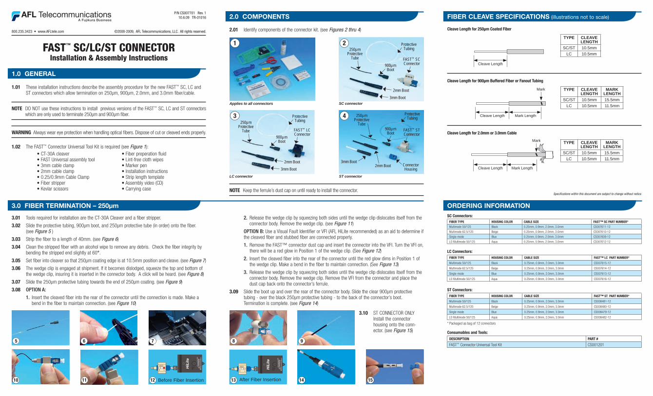
3.01 Tools required for installation are the CT-30A Cleaver and a fiber stripper.
3.02 Slide the protective tubing, 900µm boot, and 250µm protective tube (in order) onto the fiber. (see Figure 5 )
3.03 Strip the fiber to a length of 40mm. (see Figure 6)
3.04 Clean the stripped fiber with an alcohol wipe to remove any debris. Check the fiber integrity by bending the stripped end slightly at 60°.
3.05 Set fiber into cleaver so that 250µm coating edge is at 10.5mm position and cleave. (see Figure 7)
3.06 The wedge clip is engaged at shipment. If it becomes dislodged, squeeze the top and bottom of the wedge clip, insuring it is inserted in the connector body. A click will be heard. (see Figure 8)
3.07 Slide the 250µm protective tubing towards the end of 250µm coating. (see Figure 9)
3.08 OPTION A:
1. Insert the cleaved fiber into the rear of the connector until the connection is made. Make a bend in the fiber to maintain connection. (see Figure 10)
2.01 Identify components of the connector kit. (see Figures 2 thru 4)
• CT-30A cleaver• FAST Universal assembly tool• 3mm cable clamp• 2mm cable clamp• 0.25/0.9mm Cable Clamp• Fiber stripper• Kevlar scissors
• Fiber preperation fluid• Lint-free cloth wipes• Marker pen• Installation instructions • Strip length template• Assembly video (CD)• Carrying case
8
10 11
6 975
12
HO
LD1
sec
12
>POM<
Before Fiber Insertion 13 After Fiber Insertion
HO
LD1
sec
12
>POM<
14 15
Cleave Length for 900µm Buffered Fiber or Fanout Tubing
Cleave Length Mark Length
Mark TYPE CLEAVELENGTH
MARKLENGTH
SC/ST 10.5mm 15.5mmLC 10.5mm 11.5mm
Cleave Length for 250µm Coated Fiber
Cleave Length
TYPE CLEAVELENGTH
SC/ST 10.5mmLC 10.5mm
Cleave Length Mark Length
Cleave Length for 2.0mm or 3.0mm Cable
TYPE CLEAVELENGTH
MARKLENGTH
SC/ST 10.5mm 15.5mmLC 10.5mm 11.5mm
Mark
800.235.3423 • www.AFLtele.com ©2008-2009, AFL Telecommunications, LLC. All rights reserved.
1.0 GENERAL
SC Connectors:FiBer Type HOUSiNG COLOr CaBLe Size FaST™ SC parT NUMBer*
Multimode 50/125 Black 0.25mm, 0.9mm, 2.0mm, 3.0mm CS007611-12
Multimode 62.5/125 Beige 0.25mm, 0.9mm, 2.0mm, 3.0mm CS007610-12
Single-mode Blue 0.25mm, 0.9mm, 2.0mm, 3.0mm CS007609-12
LO Multimode 50/125 Aqua 0.25mm, 0.9mm, 2.0mm, 3.0mm CS007612-12
LC Connectors:FiBer Type HOUSiNG COLOr CaBLe Size FaST™ LC parT NUMBer*
Multimode 50/125 Black 0.25mm, 0.9mm, 2.0mm, 3.0mm CS007615-12
Multimode 62.5/125 Beige 0.25mm, 0.9mm, 2.0mm, 3.0mm CS007614-12
Single-mode Blue 0.25mm, 0.9mm, 2.0mm, 3.0mm CS007613-12
LO Multimode 50/125 Aqua 0.25mm, 0.9mm, 2.0mm, 3.0mm CS007616-12
ST Connectors:FiBer Type HOUSiNG COLOr CaBLe Size FaST™ ST parT NUMBer*
Multimode 50/125 Black 0.25mm, 0.9mm, 2.0mm, 3.0mm CS008481-12
Multimode 62.5/125 Beige 0.25mm, 0.9mm, 2.0mm, 3.0mm CS008480-12
Single-mode Blue 0.25mm, 0.9mm, 2.0mm, 3.0mm CS008479-12
LO Multimode 50/125 Aqua 0.25mm, 0.9mm, 2.0mm, 3.0mm CS008482-12
* Packaged as bag of 12 connectors
Consumables and Tools:
DeSCripTiON parT #
FAST™ Connector Universal Tool Kit CS001201
ORDERING INFORMATION
2.0 COMPONENTS FIBER CLEAVE SPECIFICATIONS (illustrations not to scale)
3.0 FIBER TERMINATION – 250µm
1.01 These installation instructions describe the assembly procedure for the new FAST™ SC, LC and ST connectors which allow termination on 250µm, 900µm, 2.0mm, and 3.0mm fiber/cable.
NOTe DO NOT use these instructions to install previous versions of the FAST™ SC, LC and ST connectors which are only used to terminate 250µm and 900µm fiber.
WarNiNG Always wear eye protection when handling optical fibers. Dispose of cut or cleaved ends properly.
1.02 The FAST™ Connector Universal Tool Kit is required (see Figure 1):
Specifications within this document are subject to change without notice.NOTe Keep the ferrule’s dust cap on until ready to install the connector.
2. Release the wedge clip by squeezing both sides until the wedge clip dislocates itself from the connector body. Remove the wedge clip. (see Figure 11)
OPTION B: Use a Visual Fault Identifier or VFI (AFL HiLite recommended) as an aid to determine if the cleaved fiber and stubbed fiber are connected properly.
1. Remove the FAST™ connector dust cap and insert the connector into the VFI. Turn the VFI on, there will be a red glow in Position 1 of the wedge clip. (See Figure 12)
2. Insert the cleaved fiber into the rear of the connector until the red glow dims in Position 1 of the wedge clip. Make a bend in the fiber to maintain connection. (See Figure 13)
3. Release the wedge clip by squeezing both sides until the wedge clip dislocates itself from the connector body. Remove the wedge clip. Remove the VFI from the connector and place the dust cap back onto the connector’s ferrule.
3.09 Slide the boot up and over the rear of the connector body. Slide the clear 900µm protective tubing - over the black 250µm protective tubing - to the back of the connector’s boot. Termination is complete. (see Figure 14)
3.10 ST CONNECTOR ONLY Install the connector housing onto the conn- ector. (see Figure 15)

FAST™ SC/LC/ST ConneCTorInstallation & Assembly Instructions
P/N CS007701 Rev. 1 10.6.09 TR-01016
1
Applies to all connectors
ProtectiveTubing250µm
ProtectiveTube FAST™ LC
Connector900µm Boot
2mm Boot
3
LC connector
3mm Boot
ProtectiveTubing250µm
ProtectiveTube
FAST™ STConnector
ConnectorHousing
900µm Boot
2mm Boot
4
ST connector
3mm Boot
ProtectiveTubing250µm
ProtectiveTube FAST™ SC
Connector900µm Boot
2mm Boot
2
SC connector3mm Boot
3.01 Tools required for installation are the CT-30A Cleaver and a fiber stripper.
3.02 Slide the protective tubing, 900µm boot, and 250µm protective tube (in order) onto the fiber. (see Figure 5 )
3.03 Strip the fiber to a length of 40mm. (see Figure 6)
3.04 Clean the stripped fiber with an alcohol wipe to remove any debris. Check the fiber integrity by bending the stripped end slightly at 60°.
3.05 Set fiber into cleaver so that 250µm coating edge is at 10.5mm position and cleave. (see Figure 7)
3.06 The wedge clip is engaged at shipment. If it becomes dislodged, squeeze the top and bottom of the wedge clip, insuring it is inserted in the connector body. A click will be heard. (see Figure 8)
3.07 Slide the 250µm protective tubing towards the end of 250µm coating. (see Figure 9)
3.08 OPTION A:
1. Insert the cleaved fiber into the rear of the connector until the connection is made. Make a bend in the fiber to maintain connection. (see Figure 10)
2.01 Identify components of the connector kit. (see Figures 2 thru 4)
• CT-30A cleaver• FAST Universal assembly tool• 3mm cable clamp• 2mm cable clamp• 0.25/0.9mm Cable Clamp• Fiber stripper• Kevlar scissors
• Fiber preperation fluid• Lint-free cloth wipes• Marker pen• Installation instructions • Strip length template• Assembly video (CD)• Carrying case
8
10 11
6 975
12
HO
LD1
sec
12
>POM<
Before Fiber Insertion 13 After Fiber Insertion
HO
LD1
sec
12
>POM<
14 15
Cleave Length for 900µm Buffered Fiber or Fanout Tubing
Cleave Length Mark Length
Mark TYPE CLEAVELENGTH
MARKLENGTH
SC/ST 10.5mm 15.5mmLC 10.5mm 11.5mm
Cleave Length for 250µm Coated Fiber
Cleave Length
TYPE CLEAVELENGTH
SC/ST 10.5mmLC 10.5mm
Cleave Length Mark Length
Cleave Length for 2.0mm or 3.0mm Cable
TYPE CLEAVELENGTH
MARKLENGTH
SC/ST 10.5mm 15.5mmLC 10.5mm 11.5mm
Mark
800.235.3423 • www.AFLtele.com ©2008-2009, AFL Telecommunications, LLC. All rights reserved.
1.0 GENERAL
SC Connectors:FiBer Type HOUSiNG COLOr CaBLe Size FaST™ SC parT NUMBer*
Multimode 50/125 Black 0.25mm, 0.9mm, 2.0mm, 3.0mm CS007611-12
Multimode 62.5/125 Beige 0.25mm, 0.9mm, 2.0mm, 3.0mm CS007610-12
Single-mode Blue 0.25mm, 0.9mm, 2.0mm, 3.0mm CS007609-12
LO Multimode 50/125 Aqua 0.25mm, 0.9mm, 2.0mm, 3.0mm CS007612-12
LC Connectors:FiBer Type HOUSiNG COLOr CaBLe Size FaST™ LC parT NUMBer*
Multimode 50/125 Black 0.25mm, 0.9mm, 2.0mm, 3.0mm CS007615-12
Multimode 62.5/125 Beige 0.25mm, 0.9mm, 2.0mm, 3.0mm CS007614-12
Single-mode Blue 0.25mm, 0.9mm, 2.0mm, 3.0mm CS007613-12
LO Multimode 50/125 Aqua 0.25mm, 0.9mm, 2.0mm, 3.0mm CS007616-12
ST Connectors:FiBer Type HOUSiNG COLOr CaBLe Size FaST™ ST parT NUMBer*
Multimode 50/125 Black 0.25mm, 0.9mm, 2.0mm, 3.0mm CS008481-12
Multimode 62.5/125 Beige 0.25mm, 0.9mm, 2.0mm, 3.0mm CS008480-12
Single-mode Blue 0.25mm, 0.9mm, 2.0mm, 3.0mm CS008479-12
LO Multimode 50/125 Aqua 0.25mm, 0.9mm, 2.0mm, 3.0mm CS008482-12
* Packaged as bag of 12 connectors
Consumables and Tools:
DeSCripTiON parT #
FAST™ Connector Universal Tool Kit CS001201
ORDERING INFORMATION
2.0 COMPONENTS FIBER CLEAVE SPECIFICATIONS (illustrations not to scale)
3.0 FIBER TERMINATION – 250µm
1.01 These installation instructions describe the assembly procedure for the new FAST™ SC, LC and ST connectors which allow termination on 250µm, 900µm, 2.0mm, and 3.0mm fiber/cable.
NOTe DO NOT use these instructions to install previous versions of the FAST™ SC, LC and ST connectors which are only used to terminate 250µm and 900µm fiber.
WarNiNG Always wear eye protection when handling optical fibers. Dispose of cut or cleaved ends properly.
1.02 The FAST™ Connector Universal Tool Kit is required (see Figure 1):
Specifications within this document are subject to change without notice.NOTe Keep the ferrule’s dust cap on until ready to install the connector.
2. Release the wedge clip by squeezing both sides until the wedge clip dislocates itself from the connector body. Remove the wedge clip. (see Figure 11)
OPTION B: Use a Visual Fault Identifier or VFI (AFL HiLite recommended) as an aid to determine if the cleaved fiber and stubbed fiber are connected properly.
1. Remove the FAST™ connector dust cap and insert the connector into the VFI. Turn the VFI on, there will be a red glow in Position 1 of the wedge clip. (See Figure 12)
2. Insert the cleaved fiber into the rear of the connector until the red glow dims in Position 1 of the wedge clip. Make a bend in the fiber to maintain connection. (See Figure 13)
3. Release the wedge clip by squeezing both sides until the wedge clip dislocates itself from the connector body. Remove the wedge clip. Remove the VFI from the connector and place the dust cap back onto the connector’s ferrule.
3.09 Slide the boot up and over the rear of the connector body. Slide the clear 900µm protective tubing - over the black 250µm protective tubing - to the back of the connector’s boot. Termination is complete. (see Figure 14)
3.10 ST CONNECTOR ONLY Install the connector housing onto the conn- ector. (see Figure 15)

4.01 Tools required for installation are the CT-30A Cleaver and a fiber stripper.
NOTe When using a 900µm Fanout/Breakout kit to upjacket 250µm fiber, follow the manufacturer’s instructions. After the kit is installed properly, the following procedures for FAST™ termination are applicable. The 0.25/0.9mm cable clamp is required (Part No. CS004442).
4.02 When using a 900µm Fanout/Breakout Kit:
Measure 10 inches from end of 900µm tube and place the 0.25/0.9mm tube into 900µm cable clamp. Slide the cable clamp to tighten tube down. (See Figure 16)
4.03 Slide the 900µm boot onto the fiber. (see Figure 17)
4.04 Strip the fiber to a length of 40mm by removing 10mm at a time. (see Figure 18)
4.05 From the end of the 900µm buffered fiber, place a mark at 15.5mm for SC and ST or a mark at 11.5mm for LC. (see Figure 19)
4.06 Clean the stripped fiber with an alcohol wipe to remove any debris. Check the fiber integrity by bending the stripped end slightly at 60°. (see Figure 19)
4.07 Set the stripped fiber onto the cleaver such that the 900µm buffered fiber’s edge is at the 10.5mm position and cleave. (see Figure 20)
4.08 The wedge clip is engaged at shipment. If it has become dislodged, squeeze the top and bottom of the wedge clip, insuring it is inserted in the connector body. A click will be heard. (see Figure 21)
4.09 OPTION A:
1. Insert the cleaved fiber into the rear of the connector until the connection is made. Make a bend in the fiber to maintain connection. (see Figure 22 and 23)
2. Release the wedge clip by squeezing both sides until the wedge clip dislocates itself from the connector body. Remove the wedge clip. (see Figure 24)
OPTION B: Use a Visual Fault Identifier or VFI (AFL HiLite recommended) as an aid to determine if the cleaved fiber and stubbed fiber are connected properly.
1. Remove the FAST™ connector dust cap and insert the connector into the VFI. Turn the VFI on, there will be a red glow in Position 1 of the wedge clip. (See Figure 25)
2. Insert the cleaved fiber into the rear of the connector until the red glow dims in Position 1 of the wedge clip. Make a bend in the fiber to maintain connection. (See Figure 26)
3. Release the wedge clip by squeezing both sides until the wedge clip dislocates itself from the connector body. Remove the wedge clip. Remove the VFI from the connector and place the dust cap back onto the connector’s ferrule.
4.10 Slide the boot up and over the rear of the connector body. Termination is complete. (see Figure 27)
4.11 When using a 900µm Fanout/Breakout Kit: Remove the cable clamp from the 900µm tubing.
4.12 ST CONNECTOR ONLY Install the connector housing onto the connector. (see Figure 28)
NOTe The ferrule’s dust cap should remain in place until you are ready to insert the connector.
5.01 Required components and tools. (see Figure 1)
5.02 Measure 10 inches from end of cable and place the cable into the appropriate cable clamp. Slide the cable clamp to tighten cable down. (see Figure 29)
5.03 Slide 2mm or 3mm boot onto cable. (see Figure 30)
5.04 Remove 70mm of cable jacket. (see Figure 31)
5.05 Strip 40mm of the 900µm buffered fiber by removing 10mm at a time. (see Figure 32)
5.06 From the end of the 900µm buffered fiber, place a mark at 15.5mm for SC and ST or a mark at 11.5mm for LC. (see Figure 32)
5.07 Clean the stripped fiber with an alcohol wipe to remove any debris. Check the fiber integrity by bending the stripped end slightly at 60°.
5.08 Set the stripped fiber onto the cleaver such that the 900µm buffered fiber’s edge is at the 10.5mm position and cleave. (see Figure 33)
5.09 Set connector into the Assembly Tool. (see Figure 34)
5.10 The wedge clip is engaged at shipment. If it has become dislodged, squeeze the top and bottom insuring the wedge clip is inserted into the connector body. A click will be heard. (see Figure 34)
5.11 Place cable onto the Assembly Tool cable grip. (see Figure 35)
5.12 OPTION A:
1. Insert fiber slowly into the connector until connection is made. (see Figure 35)
2. Form a bend in the fiber to maintain connection. Be sure fiber bend does not exceed top of wedge clip. (see Figure 35)
3. Release the wedge clip by squeezing both sides until the wedge clip dislocates itself from the connector body. (see Figure 36)
OPTION B: Use a Visual Fault Identifier or VFI (AFL HiLite recommended) as an aid to determine if the cleaved fiber and stubbed fiber are connected properly.
1. Remove the FAST™ connector dust cap and insert the connector into the VFI. Turn the VFI on, there will be a red glow in Position 1 of the wedge clip. (See Figure 37)
2. Insert the cleaved fiber into the rear of the connector until the red glow dims in Position 1 of the wedge clip. Make a bend in the fiber to maintain connection. (See Figure 38)
3. Release the wedge clip by squeezing both sides until the wedge clip dislocates itself from the connector body. Remove the VFI from the connector and place the dust cap back onto the connector’s ferrule.
5.13 Remove cable from the Assembly Tool cable grip.
5.14 Slide boot past the Assembly Tool cable grip. Straighten cable and return cable to the cable grip.
5.15 Divide Kevlar into two (2) equal portions. Place Kevlar into the Assembly Tool Kevlar grips on each side. Tug Kevlar lightly to ensure it’s pulled taut and 900µm buffered fiber is not bent. (see Figure 39)
5.16 Grip Kevlar on both sides of the tool to maintain tension. Screw boot onto back of connector to fix Kevlar firmly. (see Figure 40)
5.17 Remove connector from Assembly Tool.
5.19 Remove wedge clip unit from connector. (see Figure 41)
5.20 Trim excess Kevlar using Kevlar scissors. (see Figure 42)
5.21 Release and remove cable clamp. Termination is complete. (see Figure 43)
5.22 ST CONNECTOR ONLY Install the connector housing onto the connector. (see Figure 44)
NOTe The ferrule’s dust cap should remain in place until you are ready to insert the connector.
24 27 28
18 20 21
22
1716
25
HO
LD1
sec
12
>POM<
Before Fiber Insertion23 26 After Fiber Insertion
HO
LD1
sec
12
>POM<
19LC 11.5mm
SC/ST 15.5mm
LC 11.5mm
SC/ST15.5mm
32
40 4241
30 31 33 3429
36 43 4439
Kevlar Grip
35
Cable Grip
4.0 FIBER TERMINATION – 900µm
5.0 FIBER TERMINATION – 2mm and 3mm
37 Before Fiber Insertion
HO
LD1
sec
12
>POM<
38 After Fiber Insertion
HO
LD1
sec
12
>POM<
FAST™ SC/LC/ST ConneCTorInstallation & Assembly Instructions
P/N CS007701 Rev. 1 10.6.09 TR-01016
1
Applies to all connectors
ProtectiveTubing250µm
ProtectiveTube FAST™ LC
Connector900µm Boot
2mm Boot
3
LC connector
3mm Boot
ProtectiveTubing250µm
ProtectiveTube
FAST™ STConnector
ConnectorHousing
900µm Boot
2mm Boot
4
ST connector
3mm Boot
ProtectiveTubing250µm
ProtectiveTube FAST™ SC
Connector900µm Boot
2mm Boot
2
SC connector3mm Boot
3.01 Tools required for installation are the CT-30A Cleaver and a fiber stripper.
3.02 Slide the protective tubing, 900µm boot, and 250µm protective tube (in order) onto the fiber. (see Figure 5 )
3.03 Strip the fiber to a length of 40mm. (see Figure 6)
3.04 Clean the stripped fiber with an alcohol wipe to remove any debris. Check the fiber integrity by bending the stripped end slightly at 60°.
3.05 Set fiber into cleaver so that 250µm coating edge is at 10.5mm position and cleave. (see Figure 7)
3.06 The wedge clip is engaged at shipment. If it becomes dislodged, squeeze the top and bottom of the wedge clip, insuring it is inserted in the connector body. A click will be heard. (see Figure 8)
3.07 Slide the 250µm protective tubing towards the end of 250µm coating. (see Figure 9)
3.08 OPTION A:
1. Insert the cleaved fiber into the rear of the connector until the connection is made. Make a bend in the fiber to maintain connection. (see Figure 10)
2.01 Identify components of the connector kit. (see Figures 2 thru 4)
• CT-30A cleaver• FAST Universal assembly tool• 3mm cable clamp• 2mm cable clamp• 0.25/0.9mm Cable Clamp• Fiber stripper• Kevlar scissors
• Fiber preperation fluid• Lint-free cloth wipes• Marker pen• Installation instructions • Strip length template• Assembly video (CD)• Carrying case
8
10 11
6 975
12
HO
LD1
sec
12
>POM<
Before Fiber Insertion 13 After Fiber Insertion
HO
LD1
sec
12
>POM<
14 15
Cleave Length for 900µm Buffered Fiber or Fanout Tubing
Cleave Length Mark Length
Mark TYPE CLEAVELENGTH
MARKLENGTH
SC/ST 10.5mm 15.5mmLC 10.5mm 11.5mm
Cleave Length for 250µm Coated Fiber
Cleave Length
TYPE CLEAVELENGTH
SC/ST 10.5mmLC 10.5mm
Cleave Length Mark Length
Cleave Length for 2.0mm or 3.0mm Cable
TYPE CLEAVELENGTH
MARKLENGTH
SC/ST 10.5mm 15.5mmLC 10.5mm 11.5mm
Mark
800.235.3423 • www.AFLtele.com ©2008-2009, AFL Telecommunications, LLC. All rights reserved.
1.0 GENERAL
SC Connectors:FiBer Type HOUSiNG COLOr CaBLe Size FaST™ SC parT NUMBer*
Multimode 50/125 Black 0.25mm, 0.9mm, 2.0mm, 3.0mm CS007611-12
Multimode 62.5/125 Beige 0.25mm, 0.9mm, 2.0mm, 3.0mm CS007610-12
Single-mode Blue 0.25mm, 0.9mm, 2.0mm, 3.0mm CS007609-12
LO Multimode 50/125 Aqua 0.25mm, 0.9mm, 2.0mm, 3.0mm CS007612-12
LC Connectors:FiBer Type HOUSiNG COLOr CaBLe Size FaST™ LC parT NUMBer*
Multimode 50/125 Black 0.25mm, 0.9mm, 2.0mm, 3.0mm CS007615-12
Multimode 62.5/125 Beige 0.25mm, 0.9mm, 2.0mm, 3.0mm CS007614-12
Single-mode Blue 0.25mm, 0.9mm, 2.0mm, 3.0mm CS007613-12
LO Multimode 50/125 Aqua 0.25mm, 0.9mm, 2.0mm, 3.0mm CS007616-12
ST Connectors:FiBer Type HOUSiNG COLOr CaBLe Size FaST™ ST parT NUMBer*
Multimode 50/125 Black 0.25mm, 0.9mm, 2.0mm, 3.0mm CS008481-12
Multimode 62.5/125 Beige 0.25mm, 0.9mm, 2.0mm, 3.0mm CS008480-12
Single-mode Blue 0.25mm, 0.9mm, 2.0mm, 3.0mm CS008479-12
LO Multimode 50/125 Aqua 0.25mm, 0.9mm, 2.0mm, 3.0mm CS008482-12
* Packaged as bag of 12 connectors
Consumables and Tools:
DeSCripTiON parT #
FAST™ Connector Universal Tool Kit CS001201
ORDERING INFORMATION
2.0 COMPONENTS FIBER CLEAVE SPECIFICATIONS (illustrations not to scale)
3.0 FIBER TERMINATION – 250µm
1.01 These installation instructions describe the assembly procedure for the new FAST™ SC, LC and ST connectors which allow termination on 250µm, 900µm, 2.0mm, and 3.0mm fiber/cable.
NOTe DO NOT use these instructions to install previous versions of the FAST™ SC, LC and ST connectors which are only used to terminate 250µm and 900µm fiber.
WarNiNG Always wear eye protection when handling optical fibers. Dispose of cut or cleaved ends properly.
1.02 The FAST™ Connector Universal Tool Kit is required (see Figure 1):
Specifications within this document are subject to change without notice.NOTe Keep the ferrule’s dust cap on until ready to install the connector.
2. Release the wedge clip by squeezing both sides until the wedge clip dislocates itself from the connector body. Remove the wedge clip. (see Figure 11)
OPTION B: Use a Visual Fault Identifier or VFI (AFL HiLite recommended) as an aid to determine if the cleaved fiber and stubbed fiber are connected properly.
1. Remove the FAST™ connector dust cap and insert the connector into the VFI. Turn the VFI on, there will be a red glow in Position 1 of the wedge clip. (See Figure 12)
2. Insert the cleaved fiber into the rear of the connector until the red glow dims in Position 1 of the wedge clip. Make a bend in the fiber to maintain connection. (See Figure 13)
3. Release the wedge clip by squeezing both sides until the wedge clip dislocates itself from the connector body. Remove the wedge clip. Remove the VFI from the connector and place the dust cap back onto the connector’s ferrule.
3.09 Slide the boot up and over the rear of the connector body. Slide the clear 900µm protective tubing - over the black 250µm protective tubing - to the back of the connector’s boot. Termination is complete. (see Figure 14)
3.10 ST CONNECTOR ONLY Install the connector housing onto the conn- ector. (see Figure 15)

4.01 Tools required for installation are the CT-30A Cleaver and a fiber stripper.
NOTe When using a 900µm Fanout/Breakout kit to upjacket 250µm fiber, follow the manufacturer’s instructions. After the kit is installed properly, the following procedures for FAST™ termination are applicable. The 0.25/0.9mm cable clamp is required (Part No. CS004442).
4.02 When using a 900µm Fanout/Breakout Kit:
Measure 10 inches from end of 900µm tube and place the 0.25/0.9mm tube into 900µm cable clamp. Slide the cable clamp to tighten tube down. (See Figure 16)
4.03 Slide the 900µm boot onto the fiber. (see Figure 17)
4.04 Strip the fiber to a length of 40mm by removing 10mm at a time. (see Figure 18)
4.05 From the end of the 900µm buffered fiber, place a mark at 15.5mm for SC and ST or a mark at 11.5mm for LC. (see Figure 19)
4.06 Clean the stripped fiber with an alcohol wipe to remove any debris. Check the fiber integrity by bending the stripped end slightly at 60°. (see Figure 19)
4.07 Set the stripped fiber onto the cleaver such that the 900µm buffered fiber’s edge is at the 10.5mm position and cleave. (see Figure 20)
4.08 The wedge clip is engaged at shipment. If it has become dislodged, squeeze the top and bottom of the wedge clip, insuring it is inserted in the connector body. A click will be heard. (see Figure 21)
4.09 OPTION A:
1. Insert the cleaved fiber into the rear of the connector until the connection is made. Make a bend in the fiber to maintain connection. (see Figure 22 and 23)
2. Release the wedge clip by squeezing both sides until the wedge clip dislocates itself from the connector body. Remove the wedge clip. (see Figure 24)
OPTION B: Use a Visual Fault Identifier or VFI (AFL HiLite recommended) as an aid to determine if the cleaved fiber and stubbed fiber are connected properly.
1. Remove the FAST™ connector dust cap and insert the connector into the VFI. Turn the VFI on, there will be a red glow in Position 1 of the wedge clip. (See Figure 25)
2. Insert the cleaved fiber into the rear of the connector until the red glow dims in Position 1 of the wedge clip. Make a bend in the fiber to maintain connection. (See Figure 26)
3. Release the wedge clip by squeezing both sides until the wedge clip dislocates itself from the connector body. Remove the wedge clip. Remove the VFI from the connector and place the dust cap back onto the connector’s ferrule.
4.10 Slide the boot up and over the rear of the connector body. Termination is complete. (see Figure 27)
4.11 When using a 900µm Fanout/Breakout Kit: Remove the cable clamp from the 900µm tubing.
4.12 ST CONNECTOR ONLY Install the connector housing onto the connector. (see Figure 28)
NOTe The ferrule’s dust cap should remain in place until you are ready to insert the connector.
5.01 Required components and tools. (see Figure 1)
5.02 Measure 10 inches from end of cable and place the cable into the appropriate cable clamp. Slide the cable clamp to tighten cable down. (see Figure 29)
5.03 Slide 2mm or 3mm boot onto cable. (see Figure 30)
5.04 Remove 70mm of cable jacket. (see Figure 31)
5.05 Strip 40mm of the 900µm buffered fiber by removing 10mm at a time. (see Figure 32)
5.06 From the end of the 900µm buffered fiber, place a mark at 15.5mm for SC and ST or a mark at 11.5mm for LC. (see Figure 32)
5.07 Clean the stripped fiber with an alcohol wipe to remove any debris. Check the fiber integrity by bending the stripped end slightly at 60°.
5.08 Set the stripped fiber onto the cleaver such that the 900µm buffered fiber’s edge is at the 10.5mm position and cleave. (see Figure 33)
5.09 Set connector into the Assembly Tool. (see Figure 34)
5.10 The wedge clip is engaged at shipment. If it has become dislodged, squeeze the top and bottom insuring the wedge clip is inserted into the connector body. A click will be heard. (see Figure 34)
5.11 Place cable onto the Assembly Tool cable grip. (see Figure 35)
5.12 OPTION A:
1. Insert fiber slowly into the connector until connection is made. (see Figure 35)
2. Form a bend in the fiber to maintain connection. Be sure fiber bend does not exceed top of wedge clip. (see Figure 35)
3. Release the wedge clip by squeezing both sides until the wedge clip dislocates itself from the connector body. (see Figure 36)
OPTION B: Use a Visual Fault Identifier or VFI (AFL HiLite recommended) as an aid to determine if the cleaved fiber and stubbed fiber are connected properly.
1. Remove the FAST™ connector dust cap and insert the connector into the VFI. Turn the VFI on, there will be a red glow in Position 1 of the wedge clip. (See Figure 37)
2. Insert the cleaved fiber into the rear of the connector until the red glow dims in Position 1 of the wedge clip. Make a bend in the fiber to maintain connection. (See Figure 38)
3. Release the wedge clip by squeezing both sides until the wedge clip dislocates itself from the connector body. Remove the VFI from the connector and place the dust cap back onto the connector’s ferrule.
5.13 Remove cable from the Assembly Tool cable grip.
5.14 Slide boot past the Assembly Tool cable grip. Straighten cable and return cable to the cable grip.
5.15 Divide Kevlar into two (2) equal portions. Place Kevlar into the Assembly Tool Kevlar grips on each side. Tug Kevlar lightly to ensure it’s pulled taut and 900µm buffered fiber is not bent. (see Figure 39)
5.16 Grip Kevlar on both sides of the tool to maintain tension. Screw boot onto back of connector to fix Kevlar firmly. (see Figure 40)
5.17 Remove connector from Assembly Tool.
5.19 Remove wedge clip unit from connector. (see Figure 41)
5.20 Trim excess Kevlar using Kevlar scissors. (see Figure 42)
5.21 Release and remove cable clamp. Termination is complete. (see Figure 43)
5.22 ST CONNECTOR ONLY Install the connector housing onto the connector. (see Figure 44)
NOTe The ferrule’s dust cap should remain in place until you are ready to insert the connector.
24 27 28
18 20 21
22
1716
25
HO
LD1
sec
12
>POM<
Before Fiber Insertion23 26 After Fiber Insertion
HO
LD1
sec
12
>POM<
19LC 11.5mm
SC/ST 15.5mm
LC 11.5mm
SC/ST15.5mm
32
40 4241
30 31 33 3429
36 43 4439
Kevlar Grip
35
Cable Grip
4.0 FIBER TERMINATION – 900µm
5.0 FIBER TERMINATION – 2mm and 3mm
37 Before Fiber Insertion
HO
LD1
sec
12
>POM<
38 After Fiber Insertion
HO
LD1
sec
12
>POM<
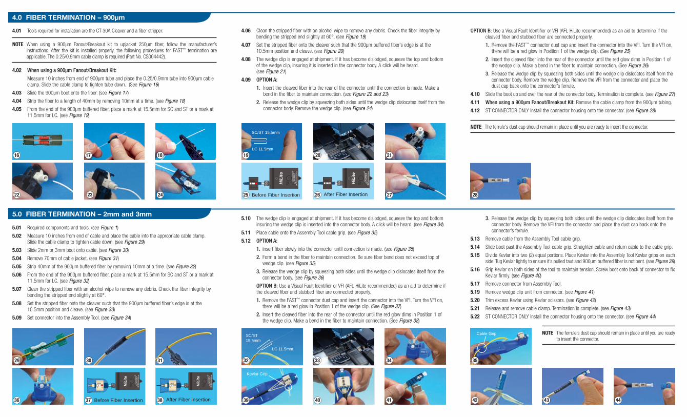