Type B Foster Wheeler Environmental Corporation - … · DOE/ORO-2155 Type B Accident Investigation...
125
May 2003 CRCC887 U. S. Department of Energy Oak Ridge Operations Office
Transcript of Type B Foster Wheeler Environmental Corporation - … · DOE/ORO-2155 Type B Accident Investigation...

May 2003
CRCC887
U. S. Department of EnergyOak Ridge Operations Office
DEPAR
TMENT OF EN
ERG
Y
UN
IT
ED
STATES OF AM
ERIC
A
DOE/ORO-2155
Type BAccident Investigation
of the April 8, 2003Electrical Arc Blast at the
Foster WheelerEnvironmental Corporation
TRU Waste Processing FacilityOak Ridge, Tennessee

DOE/ORO-2155
Type B Accident Investigation
of the April 8, 2003, Electrical Arc Blast at the
Foster Wheeler Environmental Corporation
TRU Waste Processing Facility Oak Ridge, Tennessee
May 2003
Oak Ridge Operations Office U.S. Department of Energy

This page intentionally left blank.

INDEPENDENT REPORT
his report is an independent product of the Type B Accident Investigation Board (Board) appointed by Gerald Boyd, Manager, Oak Ridge Operations Office, U.S.
Department of Energy (DOE). The Board was appointed to perform a Type B investigation of the accident and prepare an investigation report in accordance with DOE Order 225.1A, Accident Investigations. The discussion of the facts, as determined by the Board, and the views expressed in this report are not necessarily those of DOE and do not assume and are not intended to establish the existence of any legal causation, liability, or duty at law on the part of the U.S. Government, its employees or agents or contractors, their employees or agents or subcontractors at any tier, or any other party. This report neither determines nor implies liability.
T

This page intentionally left blank.

RELEASE AUTHORIZATION
On April 10, 2003, I appointed a Type B Accident Investigation Board to investigate theApril 8, 2003, electrical arc blast incident at the Foster Wheeler Environmental
Corporation Transuranic Waste Processing Facility. The responsibilities of the AccidentInvestigation Board have been satisfied with respect to this investigation . The analysis andthe identification of contributing and root causes and Judgments of Need resulting fromthis investigation were performed in accordance with Department of Energy Order 225.1A,Accident Investigations .
I accept the report of the Accident Investigation Board and authorize release of this reportfor general distribution.
Gerald G. BoydManagerOak Ridge Operations Office
Date Accepted :
~ 2
5

This page intentionally left blank.

PROLOGUE
This Type B Accident Investigation is an important reminder that the activities we carryout every day have important safety and health implications.
Many of the activities performed for the Oak Ridge Operations Office (ORO) involve theroutine use of potentially dangerous industrial equipment to accomplish the work. Thisequipment has the potential to cause serious personal injury and property damage unlessappropriate safety measures are implemented. Therefore, it is imperative that the guidingprinciples and core functions of Integrated Safety Management are carried out from thehighest level ofthe organization down to the work beingperformed.
This Type B Accident Investigation report is important in improving safety at Oak Ridge.The lessons learned contained in this report are applicable to all types of work activities .The report provides lessons on many aspects of conducting work safely and representsORO's continued commitment to support the U.S . Department of Energy's SafetyManagement System Policy .
I trust that all Federal employees and contractors supporting ORO will take the time toread this report, think about its applicability to their work, and recognize that every pieceof equipment represents a unique challenge to identify and negate its hazards. I encourageall Federal and contractor employees to vigorously continue their efforts to fullyimplement Integrated Safety Management .
eraldG. BoyManager
Oak Ridge Operations Office

This page intentionally left blank.

i
TABLE OF CONTENTS
1.1 Background................................................................................................ 1-1 1.2 Facility Description................................................................................... 1-1 1.3 Scope, Purpose, and Methodology ............................................................ 1-2
2.1 Event Description...................................................................................... 2-1 2.2 Chronology ................................................................................................ 2-2
2.2.1 Procurement................................................................................... 2-4 2.2.2 Modifications ................................................................................. 2-7 2.2.3 Initial Boiler Incident of March 3, 2003...................................... 2-10 2.2.4 Repairs After the First Incident ................................................... 2-11 2.2.5 Second Boiler Incident of April 8, 2003 ..................................... 2-11
3.1 Board Analysis of Independent Review of the Rubber Tubing ................ 3-1 3.2 Barrier Analysis ......................................................................................... 3-1
3.2.1 Barrier Analysis Narrative............................................................. 3-5 3.3 Change Analysis ........................................................................................ 3-7
3.3.1 Change Analysis Narrative .......................................................... 3-11 3.4 Events and Causal Factors ....................................................................... 3-16 3.5 Integrated Safety Management ................................................................ 3-19
APPENDICES: Appendix A – Type B Investigation Board Appointment Memorandum Appendix B – Event and Causal Factors Chart Appendix C – Receipt Inspection Report Appendix D – Independent Analysis of the Rubber Tubing Appendix E – Exhibit of Special Provisions in Contract Appendix F – Boltswitch Installation, Operation and Maintenance Manual Appendix G – Precision Boilers Operation and Maintenance Manual
TABLE OF CONTENTS ....................................................................................................i EXHIBITS AND TABLES ................................................................................................ii ACRONYMS ....................................................................................................................iii EXECUTIVE SUMMARY................................................................................................v 1.0 INTRODUCTION ............................................................................................... 1-1
2.0 FACTS ................................................................................................................. 2-1
3.0 ANALYSIS .......................................................................................................... 3-1
4.0 CONCLUSIONS AND JUDGMENTS OF NEED ............................................. 4-1 5.0 BOARD SIGNATURES...................................................................................... 5-1 6.0 BOARD MEMBERS, ADVISORS, AND STAFF ............................................. 6-1

ii
EXHIBITS AND TABLES List of Exhibits
Exhibit 1. Micarta Insulating Panel..............................................................................2-1 Exhibit 2 Dislodged Micarta Insulating Panel............................................................. 2-2 Exhibit 3. Fuse Block ...................................................................................................2-6 Exhibit 4. Two of the Removed 120V Control Transformers ......................................2-7 Exhibit 5. Original Location of One 120V Control Transformer in Panel...................2-8 Exhibit 6. Installed Unistrut® ......................................................................................2-8 Exhibit 7. Sliding Panels, Vent, and Fan......................................................................2-9 Exhibit 8. FWENC's Letter to Precision Boilers, Inc. ................................................2-12 Exhibit 9. Switchgear Breaker....................................................................................2-13 Exhibit 10. Panels After Arc Blast ...............................................................................2-13 Exhibit 11. Damaged Fuse Blocks ...............................................................................2-14 Exhibit 12. Wire With Crimping Sleeves and Without ................................................3-12 Exhibit 13. Contactors Used by Precision Boilers, Inc. ...............................................3-12 Exhibit 14. Micarta Insulating Panel............................................................................3-13 Exhibit 15. FWENC Policy E-Mail..............................................................................3-14 List of Tables Table ES-1. Judgments of Need ..................................................................................... vi Table 2-1. Event Chronology .....................................................................................2-2 Table 3-1. Barrier Analysis ........................................................................................3-2 Table 3-2. Change Analysis .......................................................................................3-8 Table 3-3. Causal Factors .........................................................................................3-16 Table 3-4. Weaknesses in Implementation of ISM Core Functions .........................3-19 Table 4-1. Judgments of Need....................................................................................4-2

iii
ACRONYMS AHJ Authority Having Jurisdiction ASME American Society of Mechanical Engineers AWG American Wire Gauge CFR Code of Federal Regulations DCN Design Change Notice DOE U. S. Department of Energy e-mail electronic mail ESH&Q Environmental, Safety, Health, and Quality FWENC Foster Wheeler Environmental Corporation ISM Integrated Safety Management JON Judgments of Need kA Kiloamperes MCC Motor Control Center MVSTs Melton Valley Storage Tanks NCR Nonconformance Report NEC National Electrical Code NEMA National Electrical Manufacturers Association NFPA National Fire Protection Association ORNL Oak Ridge National Laboratory ORO Oak Ridge Operations Office OSHA Occupational Safety and Health Administration QA Quality Assurance QC Quality Control TRU Transuranic UL Underwriters Laboratories V Volt VAC Volts Alternating Current VDC Volts Direct Current

iv
This page intentionally left blank

v
EXECUTIVE SUMMARY THE EVENT At approximately 0330 hours on April 8, 2003, a phase-to-phase arc blast occurred in the boiler electrical control panel at the Foster Wheeler Environmental Corporation (FWENC) Transuranic (TRU) Waste Processing Facility. The boiler was providing steam for the evaporator and was reportedly operating at about 10% of its capacity. The FWENC Operations staff (located in the adjacent control room building) heard a loud noise and proceeded to investigate. When the boiler building door was opened, blue smoke exhausted. The operators left the area and called the appropriate management. The operators checked the boiler main switchgear breaker in the electrical equipment building and found it in the tripped position. FWENC experienced a similar incident on March 3, 2003, in the same electrical panel in the boiler room. No injuries occurred during either incident, although two employees were present at the time of the first incident. FWENC performed an internal investigation into the initial event (Investigation Report: TRU/ALPHA Project – Boiler Electrical Short Circuit; attachment to Corporate ESQ Report 0049). After evaluating the conditions associated with the events of March 3, 2003, and April 8, 2003, the Oak Ridge Operations Office (ORO) requested that a Type B Accident Investigation be conducted in accordance with Department of Energy (DOE) Order 225.1A, Accident Investigations. The Accident Investigation Board (Board) convened on April 10, 2003, and began investigating the circumstances involving the electrical arc blast. BACKGROUND The TRU Waste Processing Facility, which is under construction in Oak Ridge, Tennessee, will process waste generated from past isotope production and research and development activities at the Oak Ridge National Laboratory. Construction began in 2000, and the facility is scheduled to become operational in 2003. ORO entered into a fixed-price contract in 1998 with FWENC to construct, operate, decontaminate, and decommission the TRU Waste Processing Facility. RESULTS AND ANALYSIS The Board reviewed the equipment procurement process, physical evidence related to the incident, modifications, and the first incident report and associated corrective actions. In the course of the investigation, Board members visited the boiler manufacturer’s facility and conducted numerous interviews with representatives of FWENC; Tetra Tech NUS, Inc.; Tennessee Associated Electric ; Precision Boilers, Inc.; Lockwood Greene; Bechtel Jacobs Company LLC; and DOE. Applicable Code of Federal Regulations, other

vi
relevant codes, and consensus standards were consulted. In addition, an independent experimental analysis of the panel material was reviewed. The Judgments of Need were developed that considered the actions necessary to prevent recurrence of this event. The Board focused on the management of the procurement, procedures, change process, and Quality Assurance (QA). It is the opinion of the Board that the procurement process inadequately identified and defined the functions and requirements for the boiler package. After installation and initial startup, FWENC management ineffectively administered the change control process, thus compromising the operational integrity of the boiler electrical panel and ultimately resulting in the event. The actions identified by the FWENC investigation and FWENC engineers following the event of March 3, 2003, were either inadequate or, in some cases, not implemented. The QA processes failed to identify the deficiencies throughout the procurement and change processes that might have averted the failure. CONCLUSIONS The Board concludes that this event and the event of March 3, 2003, were preventable. The event highlighted weaknesses in key aspects of procurement, change control, procedures, and QA. The root cause is FWENC management ineffectively administered the change control process. Although the direct cause was the improper modification of the electrical panel, the contributing causes were instrumental in the event. The electrical panel operated successfully for approximately four months without incident. Although excessive wear of the components was noted, failure did not occur until the panel was modified without sufficient evaluation and coordination with the manufacturer. The Board determined that ORO’s oversight function was adequate for the contracting mechanism used in the construction phase of the project.
Table ES-1. Judgments of Need
No. Judgment of Need Related Causal Factors JON
1 FWENC management needs to evaluate the change process and implement appropriate procedures to ensure the effective management of change and configuration control.
RC CC - 1, 2, 3, 5, 7, 8
JON 2
FWENC management needs to evaluate the current QA program and integrate a comprehensive QA/quality control component into all project aspects.
CC - 1, 2, 4, 5, 6, 7

vii
Table ES-1. Judgments of Need (continued)
No. Judgment of Need Related Causal Factors JON
3 Vendor manuals, vendor recommendations, codes, and standards need to be included or addressed in procedures, designs, and modifications.
RC CC - 2, 4, 5, 6, 7, 8
JON 4
FWENC management must ensure that procedures are reviewed, updated, or amended to reflect the current state of the equipment operation, personnel, or process.
RC CC – 2, 3, 4, 5, 6, 7
JON 5
FWENC must ensure that equipment is operated within design parameters.
CC - 6, 7
JON 6
FWENC management must ensure that corrective actions and recommendations from accidents/ incidents are addressed, implemented, and disseminated through a lessons learned program.
CC- 4, 5, 6, 7

viii
This page intentionally left blank

1-1
1.0 INTRODUCTION 1.1 Background On March 3, 2003, a phase-to-phase electrical fault occurred in the boiler control panel at the Foster Wheeler Environmental Corporation (FWENC) Transuranic (TRU) Waste Processing Facility. At approximately 0330 hours on April 8, 2003, a second phase-to-phase electrical fault occurred in the panel after being repaired from the first event. No injuries were sustained in either event. FWENC performed an internal investigation into the initial event (Investigation Report: TRU/ALPHS Project – Boiler Electrical Short Circuit, attachment to Corporate ESQ Report 0049). The U.S. Department of Energy (DOE) Oak Ridge Operations Office (ORO) Environmental Management requested an independent review of the adequacy of the FWENC investigation. The reviewer determined that “The interim Foster Wheeler occurrence report investigation concluded that metal filings (from drilling in the top of the metal panel) fell onto the electrical contacts inside the panel, thus causing the phase-to-phase fault. This reviewer does not believe that adequate evidence was presented for this being the cause. From review of the installation, and various possible occurrence causes, this reviewer was unable to pin point a definite cause.” On April 10, 2003, ORO management categorized the event of April 8, 2003, as a Type B. The ORO Manager formally appointed a Type B Accident Investigation Board (Board) to investigate the event in accordance with DOE Order 225.1A, Accident Investigations. This report documents the facts of the event and the conclusions of the Board. 1.2 Facility Description The TRU Waste Processing Facility, which is under construction in Oak Ridge, Tennessee, will process waste generated from past isotope production and research and development activities at the Oak Ridge National Laboratory (ORNL). In 1998, DOE entered into a fixed-price privatization contract with FWENC to construct, operate, decontaminate, and decommission the facility. DOE issued a Comprehensive Environmental Response, Compensation, and Liability Act Record of Decision on the processing of TRU and alpha low-level waste at ORNL in August 2000. DOE also prepared a National Environmental Policy Act environmental impact statement for the TRU Waste Processing Facility, which was issued in June 2000. FWENC is responsible for achieving compliance with all applicable environmental safety and health laws and regulations. Construction began in 2000, and the facility will become operational in 2003. Waste types to be processed at the facility include TRU waste, alpha low-level waste, mixed waste, and low-level waste. ORNL currently manages the largest inventory of remote-handled TRU/alpha low-level waste in the DOE complex, and it also manages a smaller portion of contact-handled TRU/alpha low-level waste. DOE expects to process

1-2
approximately 5,300 cubic meters of TRU/alpha low-level waste and low-level waste in the facility. Much of the waste to be processed is currently being stored or consolidated in the Melton Valley Storage Tanks (MVSTs). The liquid waste stored in the MVSTs originated from the old Hydrofracture tanks, Gunite tanks, and Bethel Valley Storage tanks. In addition, solid waste is being stored in bunkers, subsurface trenches, and metal storage buildings. Waste generated from ongoing operations at ORNL during the operation of the TRU Waste Processing Facility will also be processed in the facility. The processed TRU waste will be disposed of at the Waste Isolation Pilot Plant in Carlsbad, New Mexico. Low-level waste will be disposed of at the DOE Nevada Test Site. The TRU Waste Processing Facility is being constructed on about 20 acres of land adjoining the MVSTs. Supernate and mixed waste sludge will be transferred via above-ground pipelines from the MVSTs to the facility, where they will be concentrated before undergoing a low-temperature drying process. The arc blast event occurred in the electrical panel of the boiler used to supply heat in the drying process. 1.3 Scope, Purpose, and Methodology The Board began its activities on April 10, 2003, and completed its investigation on May 19, 2003. The scope of the Board’s investigation was to identify all relevant facts; analyze the facts to determine the direct, contributing, and root causes of the event; develop conclusions; and determine Judgments of Need that, when implemented, should prevent recurrence of the incident. The investigation was performed in accordance with DOE Order 225.1A, Accident Investigations, using the following methodology: • Facts relevant to the event were gathered through interviews and reviews of documents
and evidence. • The event scene was inspected, and photographs were taken of the scene. • Facts were analyzed to identify the causal factors using event and causal factors
analysis, barrier analysis, root cause analysis, and change analysis. • Judgments of Need for corrective actions to prevent recurrence were developed to
address the causal factors of the event.

1-3
Accident Investigation Terminology A causal factor is an event or condition in the accident sequence that contributes to the unwanted result. There are three types of causal factors: direct, which is the immediate event(s) or condition(s) that caused the accident; root cause(s), which is (are) the causal factor(s) that, if corrected, would prevent recurrence of the accident; and contributing causal factors , which are causal factors that collectively with the other causes increase the likelihood of an accident but which did not cause the accident. Event and causal factors analysis includes charting, which depicts the logical sequence of events and conditions (causal factors that allowed the event to occur), and the use of deductive reasoning to determine the events or conditions that contributed to the accident. Barrier analysis reviews the hazards, the targets (people or objects) of the hazards, and the controls or barriers that management systems put in place to separate the hazards from the targets. Barriers may be physical or administrative. Change analysis is a systematic approach that examines planned or unplanned changes in a system that caused the undesirable results related to the accident.

1-4
This page intentionally left blank

2-1
2.0 FACTS 2.1 Event Description At approximately 0330 hours on the morning of April 8, 2003, the FWENC TRU Waste Processing Facility lost power to the steam boiler. The FWENC Operations staff (located in the adjacent control room building) heard a loud noise that came from the steam boiler room. The control room operators in the adjacent control room went to investigate. When they opened the boiler building door, blue smoke exhausted. The operators left the area and called the appropriate management. The operators checked the boiler main switchgear breaker in the electrical equipment building and found it in the tripped position. The operators then checked the 120-Volt (V) power source supply located in the electrical equipment building. The breakers were still in the on position and supplying power to the boiler control circuits. At this time, the operators opened the two breakers (#28 and #30) for the 120V power in the Motor Control Center (MCC) power distribution panel to totally de-energize the separate control power source to the boiler. Next, the operators entered the boiler building and noticed that the boiler control panel doors were open and one 480V insulating panel (identified as “micarta” by electricians) was lying on the floor. (See Exhibit 1.) The remaining insulating panels of the boiler electrical panel were still in place but dislodged from their normally installed location. (See Exhibit 2.) FWENC experienced a similar incident on March 3, 2003, in the same electrical panel in the boiler room. No injuries occurred during either incident, although two employees were present at the time of the first incident. FWENC performed an internal investigation into the initial event. During the course of this investigation, it was necessary to review the FWENC report to evaluate its relevancy to the second event.
Exhibit 1. Micarta Insulating Panel

2-2
Exhibit 2. Dislodged Micarta Insulating Panel
2.2 Chronology Table 2-1 provides the events leading up to and immediately following the April 8, 2003, incident.
Table 2-1. Event Chronology
Date Event 1998 DOE entered a fixed-priced contract with FWENC 10/01/01 “Requisition Form – Equipment Solicitation” for the following items:
• Electric boiler and control system • Boiler feed/condensate return tank with complete duplex feed
pumps • Deionization vessels complete with resin • Blowdown tank complete with pump • Chemical feed package complete with tank, mixer, and pump
11/26/01 Precision Boilers, Inc., was approved to begin testing equipment at the vendor site by FWENC
12/05/01 Purchase Order 038780 for the electric boiler and control system was issued 01/03/02 Precision Boilers, Inc.’s authorized representative signed the Purchase
Order 02/27/02 Purchase Order/Change Order 038780 was amended by strikethrough that
• Changed the delivery date • Changed the 200-amp, non-fused disconnect to 2000-amp, non-
fused 03/02/02 Original delivery date for the boiler system per Purchase Order 038780

2-3
Table 2-1. Event Chronology (continued) Date Event 04/01/02 Revised delivery date for the boiler system per Purchase Order 038780 04/24/02 The vendor submitted its electrical test plan and report to FWENC 04/26/02 Boiler was shipped from vendor 04/30/02 Boiler was received on the FWENC site 08/26/02 Boiler cables and electrical panel were installed 10/28/02 Boiler was operational 11/20/02 FWENC Quality Assurance (QA) inspection for acceptance of boiler
package completed 02/03/03 (Work Request date)
Modification 1 (TRU-DCN-EE-060) • External control power source provided • Factory- installed transformers removed to provide 120V power
supply to the control panel • Installation of on/off switch
02/10/03 Last boiler operation prior to the first event: the boiler was shut down to install insulating panels (1400 hours)
02/13/03 A visual inspection was performed after the modifications. However, the electrical panel was not meggered (a device that puts direct current voltage across the device to be measured and records the resistance) as part of the inspections per the Boltswitch Installation, Operation, and Maintenance Manual from Boltswitch, Inc.
02/17/03 (Work Request date)
Modification 2a (TRU-DCN-EE-061) (Work Request SN-OPS-03-127) • Installation of barrier material support channels (Unistrut®) • Specifies installation of eight fixed panels • The vent access for the exhaust vents was blocked • “Repair boiler local electrical panel, replace any damaged
components, wire, or insulating panels. Complete any additional action req’d to close the NCR.”
• Electrical connections on the fuse blocks torqued to 40 pounds per inch, and all power connections on the contactors to 45 pounds per inch. Wire connections to the busbars tightened.
02/17/03 (Work Request date)
Modification 2b (TRU-DCN-EE-061, Revision 1) (Work Request SN-OPS-03-127) The Design Change Notice (DCN) was modified to reflect “as constructed” modifications to the electrical panel
03/03/03 Initial boiler incident 03/03/03 Nonconformance Report (NCR) – 77 opened 03/03/03 Work Suspension issued by the Operations Manager 03/03/03 FWENC Construction inspection of electrical panel 03/04/03 DOE required FWENC to issue an Occurrence Report 03/04/03 FWENC Operations inspection of electrical panel 03/04/03 FWENC Engineering inspection of electrical panel 03/04/03 Vendor Inspection completed by Precision Boilers, Inc.
2-4
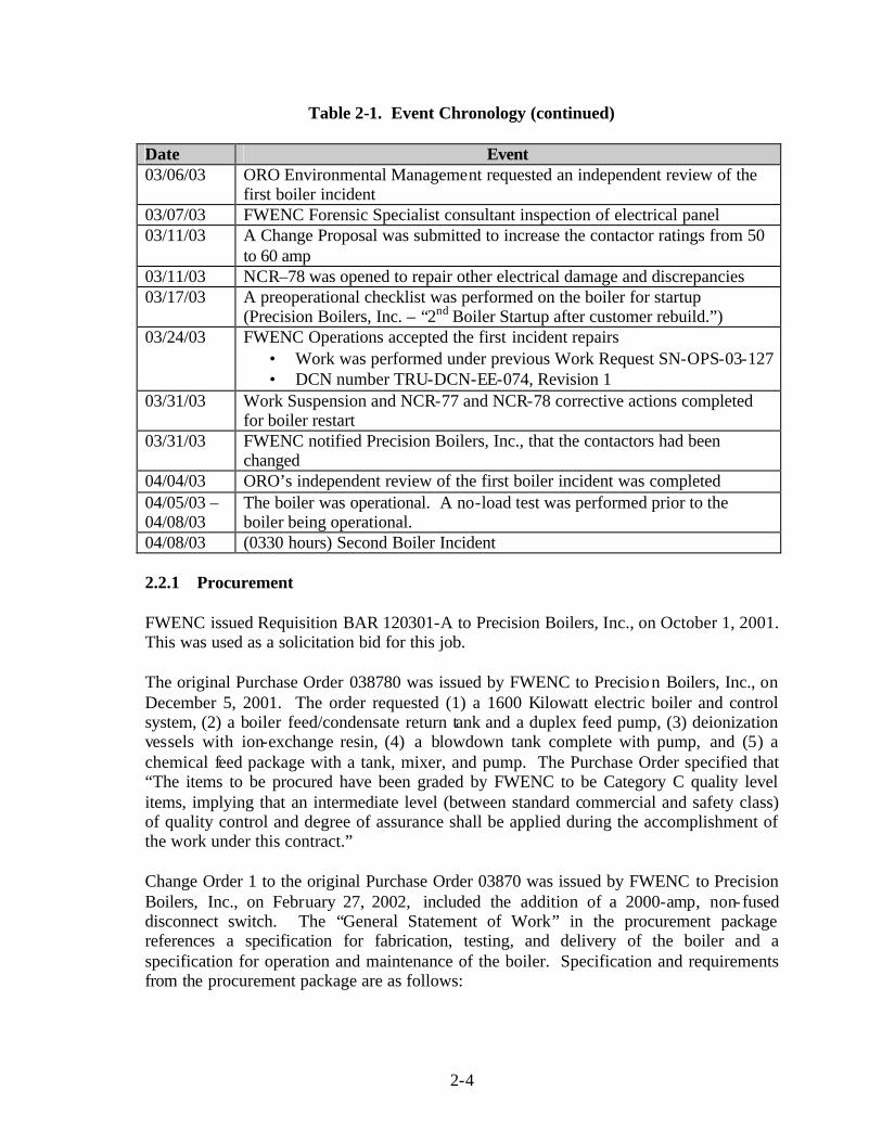
Table 2-1. Event Chronology (continued) Date Event 03/06/03 ORO Environmental Management requested an independent review of the
first boiler incident 03/07/03 FWENC Forensic Specialist consultant inspection of electrical panel 03/11/03 A Change Proposal was submitted to increase the contactor ratings from 50
to 60 amp 03/11/03 NCR–78 was opened to repair other electrical damage and discrepancies 03/17/03 A preoperational checklist was performed on the boiler for startup
(Precision Boilers, Inc. – “2nd Boiler Startup after customer rebuild.”) 03/24/03 FWENC Operations accepted the first incident repairs
• Work was performed under previous Work Request SN-OPS-03-127 • DCN number TRU-DCN-EE-074, Revision 1
03/31/03 Work Suspension and NCR-77 and NCR-78 corrective actions completed for boiler restart
03/31/03 FWENC notified Precision Boilers, Inc., that the contactors had been changed
04/04/03 ORO’s independent review of the first boiler incident was completed 04/05/03 – 04/08/03
The boiler was operational. A no-load test was performed prior to the boiler being operational.
04/08/03 (0330 hours) Second Boiler Incident 2.2.1 Procurement FWENC issued Requisition BAR 120301-A to Precision Boilers, Inc., on October 1, 2001. This was used as a solicitation bid for this job. The original Purchase Order 038780 was issued by FWENC to Precision Boilers, Inc., on December 5, 2001. The order requested (1) a 1600 Kilowatt electric boiler and control system, (2) a boiler feed/condensate return tank and a duplex feed pump, (3) deionization vessels with ion-exchange resin, (4) a blowdown tank complete with pump, and (5) a chemical feed package with a tank, mixer, and pump. The Purchase Order specified that “The items to be procured have been graded by FWENC to be Category C quality level items, implying that an intermediate level (between standard commercial and safety class) of quality control and degree of assurance shall be applied during the accomplishment of the work under this contract.” Change Order 1 to the original Purchase Order 03870 was issued by FWENC to Precision Boilers, Inc., on February 27, 2002, included the addition of a 2000-amp, non-fused disconnect switch. The “General Statement of Work” in the procurement package references a specification for fabrication, testing, and delivery of the boiler and a specification for operation and maintenance of the boiler. Specification and requirements from the procurement package are as follows:

2-5
(a) Equipment Specification T-CM-FW-S-ME-006 for fabrication, testing, and QA of the boiler was issued on September 6, 2001, and revised on November 30, 2001. This document requires compliance with the American Society of Mechanical Engineers Boiler and Pressure Vessel Code and certain standards issued by National Fire Protection Association (NFPA), National Electrical Code (NEC), National Electrical Manufacturers Association (NEMA), American Society of Nondestructive Testing, American Welding Society, Instrument Society of America, and Manufacturers Standardization Society. In Paragraph 3.7, “Electrical, ” FWENC requires a single-point power source for all 120V and 480V power in the panel and a fused 120V transformer for control circuits and branch circuits. This system was installed by the vendor.
Section 3.8 requires the electrical panel to be grounded to the major skid beams, and it states that the skid beams were connected to the facility ground by FWENC Construction personnel.
Section 3.10 requires the vendor to design for an ambient outdoor temperature of 92°F. This is consistent with average summer temperatures for the Knoxville area.
Attachment 3, “Data Sheet,” of this specification requires the boiler to be Underwriters Laboratory (UL) listed and to bear the UL label. The boiler is, in fact, UL listed, as was verified by the Board’s contacts with UL.
(b) Specification T-CM-FW-S-00-009, “Operation and Maintenance Data,” gives
requirements for vendor submission of data on the boiler system, such as operations and maintenance manuals, training requirements, drawings submittals, etc.
(c) FWENC document T-CM-FW-A-QP-001/R2, Quality Assurance Program
Description, describes the FWENC QA Program. It also includes requirements for review of the procurement package and technical specifications by the QA; Environment, Safety, and Health; and Purchasing organizations, for design reviews and review of subcontractor-submitted documents by FWENC staff, and for inspection and acceptance testing by the QA staff.
(d) Exhibit A-14 of the contract requires the vendor to comply with all Federal, state,
and local laws and regulations (see Appendix D), including Occupational Safety and Health Administration (OSHA) and the FWENC Project Rules Handbook of safety and health work practice rules and guidelines.
(e) A procurement submittal required of the vendor was its operation and maintenance
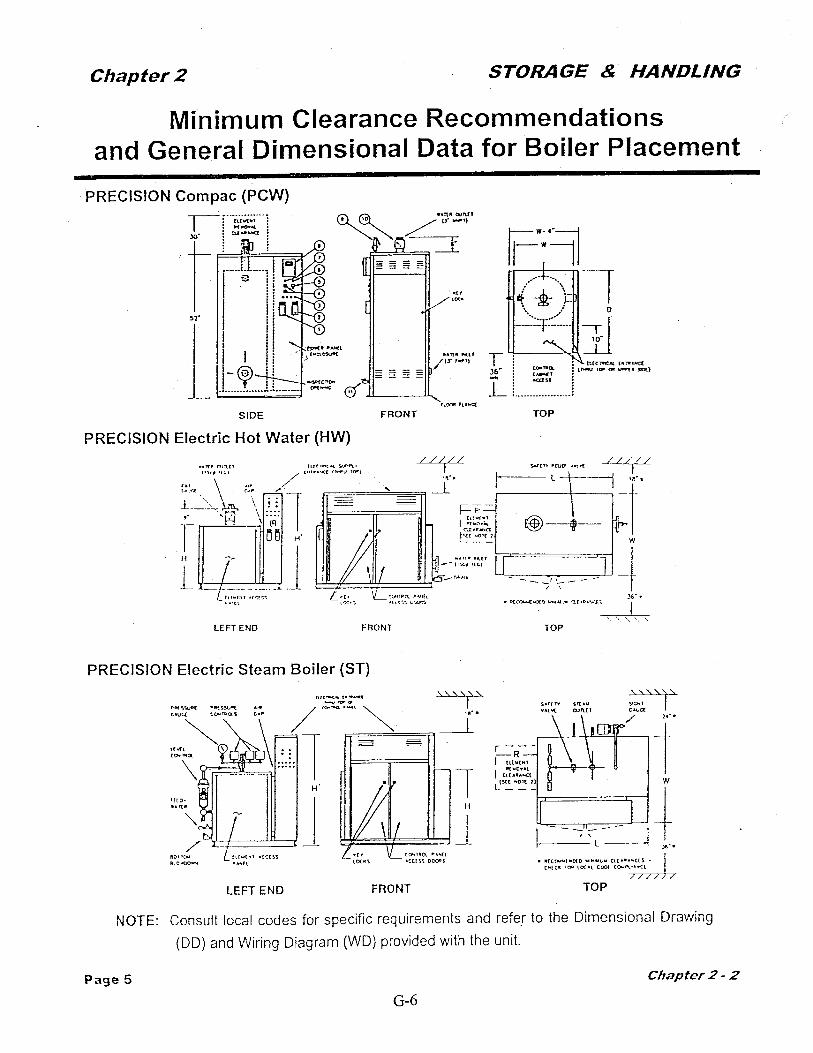
manual. The Precision Boilers Operation and Maintenance Manual requires in Section 2.D that “If the boiler is to be placed in a room with little or no ventilation, a supply of ducted filtered air may have to be brought to the lower portion of the control cabinet to limit the control cabinet interior temperature to 50°C (122°F) maximum.” No ducted, filtered air was supplied to the panel to ensure adequate

2-6
cooling. The temperature inside the panel could not be verified, since no temperature monitoring sensors were installed inside the electrical panel.
The fuse blocks were manufactured by the Bussman Company. (See Exhibit 3.) The Bussman Company recommended the use of #6 American Wire Gauge (AWG) or, with a safety factor, #4 AWG for connections, based on design specifications, application, and panel components, as stated in the Bussman Electrical Handbook and as taken from the 2002 NEC Table 310.16. (See the following web address: http://www.bussman.com/library/docs/spd02/SPBSection04.pdf.) The original factory design shows #6 AWG on the drawings, but FWENC and Precision Boilers, Inc., representatives maintained that this was a mistake in the drawings and that the intent was to use #8 AWG. The fact that #8 AWG had been installed instead of #6 AWG was noted in March 2003 during a detailed inspection of the electrical panel following the first incident. The corrective action for this finding was to change the drawings to show #8 AWG as being “as constructed.” The FWENC Receipt Inspection Report, ultimately completed on November 20, 2002, documents that the boiler meets “PO, drawing, specification requirements.” An inspection by the FWENC Electrical Supervisor, documented on November 20, 2002, also does not identify an issue with #8 AWG being installed instead of #6 AWG. (See Appendix C to this report for copies of the FWENC records documenting this issue.) FWENC NCR 2003-TRU-078, dated March 12, 2003, states that “Power wiring from bus bars to fuse blocks is #8 AWG. Vendor drawing WD-B011003 (Part of T-UT-52-A-EE-001) shows that wire as #6 AWG.” On March 18, 2003, FWENC DCN TRU-DCN-EE-074, Revision 1, was issued with a note to “Notify boiler supplier of contactor and wiring problem. Have him correct and resubmit WO-B011003 (Part of T-UT-52-A-EE-001). Note 3 from #6 AWG to #8 AWG, as delivered.”
Exhibit 3. Fuse Block

2-7
2.2.2 Modifications The electrical panel associated with the boiler contains a 120V control panel and a 480V power feed for the boiler heater elements. Operations personnel requiring access to the control panel to adjust boiler timing sequences are exposed to the hazards associated with the 480V components of the panel as originally designed. This appears to be the basis for providing an external 120V power source to the control panel. The micarta insulating panels were installed to establish separation of the different voltage systems. An internal FWENC electronic mail (e-mail) message (see Exhibit 15) dated November 8, 2002, from the Environment, Safety, Health, and Quality (ESH&Q) Manager states “that a number of pieces of equipment at the Waste Processing Facility may not have the ability to be worked on in a de-energized condition. In addition, due to the type of maintenance/repair required, appropriate electrical PPE may not be able to be worn while performing work.” Electrical workers interviewed stated that the requirements of the e-mail pertained to work on panels with voltages exceeding 24V. FWENC made the following modifications to the electrical panel on the boiler purchased from Precision Boilers, Inc. However, Precision Boilers, Inc., was not consulted about the potential impacts on performance and/or the suitability of the proposed changes to the electrical panel. Modification 1 (2/03/03) – DCN TRU-DCN-EE-060 (Work Request SN-CON-03-003)
• Added a 120V external power source to the control panel inside the boiler electrical panel.
• Removed the 480V to 120V transformers installed by the manufacturer in the electrical panel to provide 120V power to the control panel. (See Exhibits 4 and 5.)
• Installed a Square D Class 9001 on/off selector switch with legend. The switch was mounted on the side of the control cabinet above the emergency stop switch. The purpose of the switch is to provide control of the 120V power source to the control panel at the boiler electrical panel.
Exhibit 4. Two of the Removed 120V Control Transformers

2-8
Exhibit 5. Original Location of One 120V Control Transformer in Panel
Modification 2a (2/17/03) – DCN TRU-DCN-EE-061 (Work Request SN-CON-03-004)
• Installed support channels (Unistrut®) necessary to support the insulating barrier material. (See Exhibit 6.)
Exhibit 6. Installed Unistrut®

2-9
• This DCN defines the installation of eight fixed insulating panels to segregate the worker from the 480V power source. The specification for the barrier material to be installed is 600V, 1/8- inch insulating boards.
• The insulating material plate dimensions specified in the DCN do not provide vent access for the cabinet fans (bottom) or the exhaust vents (top). (See Exhibit 7.)
Exhibit 7. Sliding Panels, Vent, and Fan
Modification 2b (2/17/03) – DCN TRU-DCN-EE-061, Revision 1 (Work Request SN-CON-03-004)
• The DCN was modified to reflect the “as constructed” modification to the electrical panel.
• The revision provides for installation of insulating barrier material in the sliding panels and the horizontal Unistrut® support.
• The specification for the actual barrier material to be installed is 600V, 1/8- inch insulating boards.
FWENC’s restart of the boiler system was in accordance with T-UT-FW-P-OP-504, Boiler, Steam, and Condensate Systems, Revision 0, which did not incorporate the revisions to the boiler electrical panel.

2-10
2.2.3 Initial Boiler Incident of March 3, 2003 In the course of the investigation, it was necessary to review the investigative report (Corporate ESQ Report 0049) prepared by FWENC on the boiler electrical short circuit of March 3, 2003. It is not the charter or intent of the Board to dispute the findings discussed in the report but rather to evaluate the event of April 8, 2003, including all relevant facts. Prior to the failure, the boiler had been operated until February 10, 2003. At that time, the boiler had been shut down, a lockout/tagout had been installed so that nonconductive guard panels could be installed as a safety enhancement (per the company requirements), and work had been performed on some flow control valves in the system. This work was completed on February 13, 2003, and the lockout/tagout was removed. The FWENC Operations personnel completed a walkdown of the system to verify that all lockout/tagouts were clear on March 3, 2003. On March 3, 2003, the boiler panel experienced the first phase-to-phase fault, tripping the circuit breaker. The report noted the sequence of events as “A wet waste operator (WWO) then proceeded to start-up the system in accordance with T-UT-FW-P-OP-504, Rev. 0. The WWO opened the main steam isolation valve and verified that all the individual heater elements were off. The WWO then proceeded to close the main 480-volt disconnect switch that would energize the 480-volt power sources in the boiler control panel.” . . . “Following the closure of the switch (at approximately 2:00 p.m.) a phase-phase electrical short circuit occurred immediately.” In response to this event, FWENC performed an investigation and issued corporate ESQ Report 0049 on March 14, 2003. FWENC’s root cause for the short circuit event concludes that “there may have been environmental factors that individually or in combination affected the phase-to-phase continuity across the fuse block (moisture, metal shavings, broken wires, or others) and physically initiated the short-circuit event. However the ultimate root cause was found to be the lack of procedural controls for testing and verifying the integrity of a high-amperage electrical panel following modification of the panel and/or following shutdown of the panel for an extended period.” ORO Environmental Management requested an independent review of the adequacy of the FWENC investigation. The review determined that “The interim Foster Wheeler occurrence report investigation concluded that metal filings (from drilling in the top of the metal panel) fell onto the electrical contacts inside the panel, thus causing the phase to phase fault. This reviewer does not believe that adequate evidence was presented for this being the cause. From review of the installation, and various possible occurrence causes, this reviewer was unable to pinpoint a definite cause.”

2-11
2.2.4 Repairs After the First Incident Incident Repair/Modification 3 (3/24/03) – DCN TRU-DCN-EE-074, Revision 1 (Work Request SN-OPS-03-127)
• Repaired the boiler electrical panel and replaced any damaged components, wires, or insulating panels and completed any additional actions required to close the NCR.
• Removed/replaced damaged fuse blocks o A1 through A4 o B1 through B6 o C1 through C6 o D1 through D6 o C10
• Replaced damaged 125°C conductors from busbars to fuse blocks with #8 AWG 150°C conductors (no crimping sleeves used).
• Replaced all bare conductors from the fuse blocks to the contactors with #8 AWG 150°C conductors.
• Replaced all contactors with Cutler Hammer components with a 60-amp rating for inductive loads and a 75-amp rating for resistive loads.
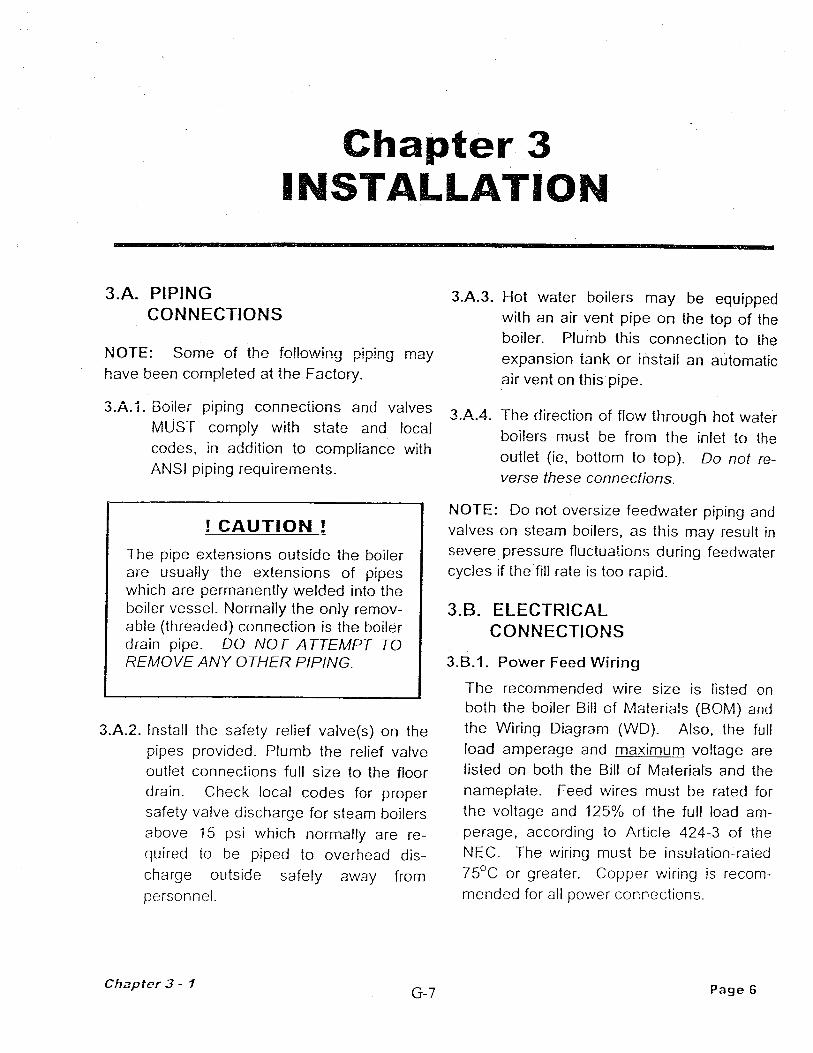
The boiler resumed operation after repairs. FWENC’s restart of the boiler system was in accordance with T-UT-FW-P-OP-504, Boiler, Steam, and Condensate Systems, Revision 2. Precision Boilers, Inc., was formally notified about the repairs in a letter dated March 31, 2003. (See Exhibit 8.) 2.2.5 Second Boiler Incident of April 8, 2003 FWENC purchased the boiler for the TRU Waste Processing Facility from Precision Boilers, Inc., of Morristown, Tennessee, and it was delivered in April 2002. The unit is rated at 1,600 kilowatts and has 40 individual three-phase circuits to power its heaters at 480V. The boiler control panel was provided in a NEMA 12 enclosure (intended for indoor use) and was UL listed. The main power source for the TRU Waste Processing Facility is supplied at 13.8 kilovolots (kV). This system feeds a Delta (13.8kV) to WYE (480/277V) transformer, although the manufacturer specifically warns against using the WYE or Star configuration for the boiler (Chapter 3.B.3, page 7, Precision Boilers Operation and Maintenance Manual). The 480V electrical power is provided to the panel from a 480V switchgear breaker. The breaker has a 3,200-ampere frame and 2,500-ampere trip rating. According to FWENC’s engineering calculations, the available fault current from the switchgear is approximately 43,000 amperes. Exhibit 9 shows the switchgear breaker supplying the 480V to the boiler.

2-12
Exhibit 8. FWENC’s Letter to Precision Boilers, Inc.

2-13
Exhibit 9. Switchgear Breaker
On the morning of the April 8, 2003, incident, the outside temperature was approximately 58°F, and the relative humidity was approximately 94%. The estimated temperature in the boiler building at the time of the event ranged between 90°F to 95°F. A power loss was experienced at 0330 hours in the boiler room. When the operators investigated, they noticed the condition explained in Section 2.1, “Event Description.” The investigation of the event revealed that a phase-to-phase fault had occurred inside the boiler panel. This developed into a three-phase fault due to the ionized gases and the 480V clearances. This phase-to-phase short resulted in the copper vaporization and spray inside the panel. (See Exhibit 10.)
Exhibit 10. Panels After Arc Blast

2-14
This condition was evident after both events. These copper vapors are easily sprayed and can result in additional short circuits, such as those seen on the other fuse blocks in the electrical control panel. (See Exhibit 11.)
Exhibit 11. Damaged Fuse Blocks
The available fault current at the boiler is approximately 43.2 kiloamperes (kA) (based on calculations by General Electrical as a part of the original purchase of the electrical equipment) “. . . which would mean that the short circuit magnitude could have potentially been in the range of 16.4kA to 38.4kA. Since the trip indication on the breaker indicated that the short circuit was at 22.4kA or above, the actual short circuit was in the approximate range of 22.4kA to 38.4kA.” An electrical fault of this magnitude can initiate all of the following:
• Temperatures in the range of 35,000ºF • Pressure waves in excess of 2,000 pounds per square foot traveling at speeds in
excess of 740 miles per hour • Decibel sound waves in excess of 165 decibels • Molten metal and shrapnel • Copper vapors in excess of 1,000ºC traveling at speeds of approximately 740 miles
per hour • Intense light and radiation waves in excess of 50 cal/cm2 traveling in excess of
670,000,000 mph
2-15
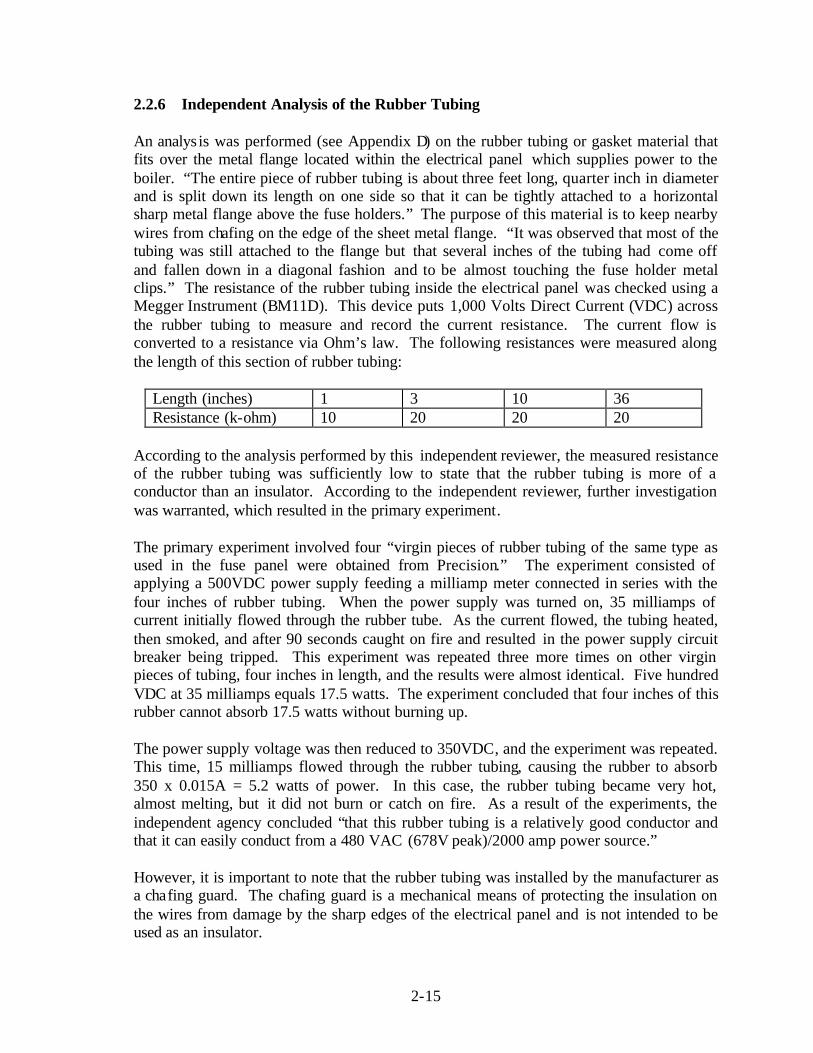
2.2.6 Independent Analysis of the Rubber Tubing An analys is was performed (see Appendix D) on the rubber tubing or gasket material that fits over the metal flange located within the electrical panel which supplies power to the boiler. “The entire piece of rubber tubing is about three feet long, quarter inch in diameter and is split down its length on one side so that it can be tightly attached to a horizontal sharp metal flange above the fuse holders.” The purpose of this material is to keep nearby wires from chafing on the edge of the sheet metal flange. “It was observed that most of the tubing was still attached to the flange but that several inches of the tubing had come off and fallen down in a diagonal fashion and to be almost touching the fuse holder metal clips.” The resistance of the rubber tubing inside the electrical panel was checked using a Megger Instrument (BM11D). This device puts 1,000 Volts Direct Current (VDC) across the rubber tubing to measure and record the current resistance. The current flow is converted to a resistance via Ohm’s law. The following resistances were measured along the length of this section of rubber tubing:
Length (inches) 1 3 10 36 Resistance (k-ohm) 10 20 20 20
According to the analysis performed by this independent reviewer, the measured resistance of the rubber tubing was sufficiently low to state that the rubber tubing is more of a conductor than an insulator. According to the independent reviewer, further investigation was warranted, which resulted in the primary experiment. The primary experiment involved four “virgin pieces of rubber tubing of the same type as used in the fuse panel were obtained from Precision.” The experiment consisted of applying a 500VDC power supply feeding a milliamp meter connected in series with the four inches of rubber tubing. When the power supply was turned on, 35 milliamps of current initially flowed through the rubber tube. As the current flowed, the tubing heated, then smoked, and after 90 seconds caught on fire and resulted in the power supply circuit breaker being tripped. This experiment was repeated three more times on other virgin pieces of tubing, four inches in length, and the results were almost identical. Five hundred VDC at 35 milliamps equals 17.5 watts. The experiment concluded that four inches of this rubber cannot absorb 17.5 watts without burning up. The power supply voltage was then reduced to 350VDC, and the experiment was repeated. This time, 15 milliamps flowed through the rubber tubing, causing the rubber to absorb 350 x 0.015A = 5.2 watts of power. In this case, the rubber tubing became very hot, almost melting, but it did not burn or catch on fire. As a result of the experiments, the independent agency concluded “that this rubber tubing is a relatively good conductor and that it can easily conduct from a 480 VAC (678V peak)/2000 amp power source.” However, it is important to note that the rubber tubing was installed by the manufacturer as a chafing guard. The chafing guard is a mechanical means of protecting the insulation on the wires from damage by the sharp edges of the electrical panel and is not intended to be used as an insulator.

2-16
This page intentionally left blank.

3-1
3.0 ANALYSIS The Board used several analytical techniques to determine the causal factors of the incident. Events and causal factors were charted using the Integrated Safety Management (ISM) core functions. The Board used change and barrier analysis techniques to analyze the facts and identify the causes of the incident. The causal factors related to weaknesses in implementation of the ISM core functions collectively contributed to the incident. The causal factors contributed to the incident. The Judgments of Need are presented in Table 4-1. 3.1 Board Analysis of Independent Review of the Rubber Tubing A review of the independent analysis of the rubber tubing was performed. The investigator indicated that it is entirely possible that the rubber tubing was the foreign material that could have initiated the arcing in the 480 Volts Alternating Current (VAC)/2000 amp power panel. The experiment involved only one small piece of virgin rubber tubing that was obtained from Precision Boilers, Inc., and the other pieces of rubber tubing tested came from inside the electrical panel that had experienced two electrical arc blasts. Therefore, it is the Board’s opinion that sufficient data was not available to substantiate this conclusion. 3.2 Barrier Analysis Barrier analysis is based on the premise that hazards are associated with all accidents/ events. Barriers are developed into a system or work process to protect personnel and equipment from hazards. For an accident/event to occur, there must be a hazard that comes into contact with a target because the barriers or controls were not in place, not used, modified, or failed. A hazard is the potential for unwanted energy flow to result in an incident or other adverse consequence. A target is a person or object that a hazard may damage, injure, or fatally harm. A barrier is any means used to control, prevent, or impede the hazard from reaching the target, thereby reducing the severity of the resultant accident or adverse consequence. The results of the barrier analysis are used to support the development of the causal factors. Table 3-1 contains the barrier analysis.

3-2
Table 3-1. Barrier Analysis
Barrier Purpose Why Did the Barrier Fail? Analysis/Effect on Accident
1. Adequate Definition of Equipment Function and Requirements
To ensure that equipment obtained is suitable for the intended purpose
1. The intended application for the equipment was not clearly defined.
2. Off-the-shelf equipment was not properly evaluated for the specific application.
3. Additional system requirements were identified after installation, prompting equipment modifications.
4. Components added during modification were not properly evaluated for application.
A failure to sufficiently define all parameters pertaining to the intended use of the boiler prompted modifications that ultimately resulted in a system failure.
2. Operating/Maintenance Procedures
To make certain that vendor requirements are defined pertaining to proper equipment operation and personnel safety
1. The vendor’s operation and maintenance manual was not followed or integrated into FWENC’s procedures.
2. The procedures were not revised to address equipment modifications.
Certain aspects of the vendor’s manual were not followed, resulting in improper maintenance and operation of the equipment.

3-3
Table 3-1. Barrier Analysis (continued)
Barrier Purpose Why Did the Barrier Fail? Analysis/Effect on Accident 3. Evaluation of Modifications
To evaluate changes to operating parameters of equipment being modified in order to assess potential operational and safety impacts
1. Modifications were performed without evaluation of their impact on equipment performance.
2. Components were selected for the cabinet size, not necessarily for functionality.
3. Modifications were not communicated to the manufacturer for evaluation of their impact on the equipment design parameters.
Modifications (components, wire, insulating panels, power supply, and contactors) were not evaluated for their potential impacts on the electrical panel’s performance. The result was elevated temperatures inside the electrical panel.
4. Configuration Management To provide for a systematic evaluation of proposed modifications while maintaining control of system components
Key components of the change process were not evident.
The FWENC change process should include the following:
1. TRU Project Change Proposal
2. DCN 3. Work Request 4. Performance of the work 5. QA (verification)
Analysis of a matrix reveals that work was completed without timely completion of certain program aspects.

3-4
Table 3-1. Barrier Analysis (continued)
Barrier Purpose Why Did the Barrier Fail? Analysis/Effect on Accident 5. Regulations and OSHA Compliance
Establishes parameters for qualified/unqualified workers that ultimately provide for worker safety
Installation of the insulating panel could circumvent certain requirements, allowing unqualified workers inside the energized electrical panel.
The installation of the insulating panels resulted in elevated temperatures inside the electrical panel, which ultimately resulted in a failure of the electrical panel.
6. NEC Regulations To provide for personnel safety and equipment protection
Modifications to the UL-listed equipment resulted in the equipment functioning outside the parameters of that listing.
Modifications voided the UL listing of the electrical panel, resulting in the equipment failure.
7. QA/Quality Control (QC) To ensure and validate quality
The FWENC QA Program failed to identify the deficiencies in procurement, the change process, and procedures.
1. The equipment was not configured as specified in the procurement.
2. The installation was not in accordance with the vendor’s operating and maintenance manual.
3. The current procedure does not reflect the existing configuration of the equipment.
4. “As designed” drawings were modified to reflect the “as constructed” installation of #8 AWG wire instead of #6 AWG wire six months after acceptance, installation, and operation.
5. FWENC failed to adhere to its change control procedure.

3-5
3.2.1 Barrier Analysis Narrative During the procurement process, the functions and requirements for the boiler were not adequately defined. FWENC’s Engineering, Operations, QA, and Health and Safety organizations were not adequately involved in the process to clearly identify the intended location and application of the equipment. This resulted in a decision to use a generic-designed boiler that subsequently required modification. A procurement submittal required the vendor to provide an operation and maintenance manual. The Precision Boilers Operation and Maintenance Manual was supplied, but key elements were not followed or appropriately integrated into FWENC’s procedures. For example, the Precision Boilers Operation and Maintenance Manual states:
!Caution! “If the boiler is to be placed in a room with little or no ventilation, a supply of ducted filtered air may have to be brought to the lower portion of the control cabinet to limit the control cabinet interior temperature to 50°C (122°F) maximum.”
No ducted, filtered air was supplied to the panel to ensure adequate cooling. The temperature inside the panel could not be verified, since temperature monitoring sensors were not installed inside the electrical panel. The Precision Boilers Operation and Maintenance Manual, Chapter 4, paragraph C.3, advises the user that:
“All branch circuit connections should be tightened to 35-40 inch lbs torque to avoid component damage from heat build-up.”
The Electrical Supervisor’s notes regarding the changes/repairs performed as prescribed in Work Request WR-SN-OPS-127 state that “I torque all electrical connections on the fuse blocks to 40 lb- in, and all power connections on the contactors to 45 lb- in.” There are no records of torquing other than the Electrical Supervisor’s notes regarding “lb- in” (pounds per inch) use to secure the connections to the busbar. Modifications to the boiler electrical panel were necessary for the equipment to meet the facility’s operational requirements. The modifications (components, wire, insulating panels, power supply, and contactors) were not evaluated for their potential impacts on the electrical panel’s performance. The modifications were not communicated to the manufacturer for evaluation of their impact on the equipment design parameters. This resulted in voiding the UL listing and manufacturer’s warranty of the electrical panel. Certain aspects of the FWENC change process were not evident through the course of the modifications to key components of the electrical panel. The normal FWENC change process should include the following:

3-6
• TRU Project Change Proposal • DCN • Work Request • Performance of the modification/maintenance • QA (verification)
A review of the documents related to the modifications performed on the electrical panel shows that the work was completed without proper, complete, and traceable documentation. In fact, modification to the electrical panel to install the insulating panel could circumvent certain requirements, allowing unqualified workers inside the energized electrical panel. OSHA states that a Qualified Person is “one who has skills and knowledge related to the construction and operation of the electrical equipment and installations and has received safety training on the hazards involved.” OSHA further states that additional requirements for qualified persons shall, at a minimum, be trained in and be familiar with the following:
(1) The skills techniques necessary to distinguish exposed live parts from other parts of electric equipment
(2) The skills and techniques necessary to determine the nominal voltage of exposed
live parts
(3) The clearance distances specified in Title 29 Code of Federal Regulations (CFR) Part 1910.333(c) and the corresponding voltages to which the qualified person will be exposed.
The modifications to the electrical panel were made without contacting or obtaining approval of the manufacturer. If the approval of the manufacturer is not obtained, approval of the modification should be obtained from the Authority Having Jurisdiction (AHJ). This process should follow the guidance in the DOE Electrical Safety Handbook, which addresses modifications and who should approve these modifications. The handbook states that when modifications are made to equipment, an individual designated as the electrical AHJ should approve the modifications. The AHJ should possess such executive ability as is required for performance of the position and should have thorough knowledge of standard materials and work practices used in the installation, operation, construction, and maintenance of electrical equipment. The AHJ should, through experience or education, be knowledgeable of the requirements contained in the OSHA standards, the NEC, the National Electrical Safety Code, DOE requirements, and other appropriate local, state, and national standards. The AHJ should be responsible to interpret codes, regulations and standards and to approve equipment, assemblies, or materials. In addition to the DOE Electrical Safety Handbook, NEC 80.19 and 90.4-2002 state that “By special permission, the AHJ may waive specific requirements in this Code or permit alternative methods where it is assured that equivalent objectives can be achieved by establishing and maintaining effective safety.”

3-7
NEC also states in 90.7-2002 that “It is the intent of this Code that factory- installed internal wiring or the construction of equipment need not be inspected at the time of installation of the equipment, except to detect alterations or damage, if the equipment has been listed by a qualified electrical testing laboratory that is recognized as having the facilities described in the preceding paragraph and that requires suitability for installation in accordance with this Code.” However, the modifications to the equipment at the FWENC TRU Waste Processing Facility were made without approval of the manufacturer or the AHJ and resulted in the UL listing and manufacturer’s warranty being voided. Subsequent to the procurement of the equipment, a FWENC QA receipt inspection and verification of all equipment components did not identify discrepancies between the “as constructed” configuration and the “as received” configuration of the electrical panel. Specifically, the drawings were modified to reflect an “as constructed” installation of #8 AWG instead of #6 AWG without an appropriate revision date identified on the drawing. Additional programmatic deficiencies of the FWENC QA Program include the following:
• Equipment was not configured as specified in procurement. • Installation was not in accordance with the vendor’s operating and maintenance
manual.
• The current procedure does not reflect the existing configuration of the equipment.
• FWENC failed to adequately adhere to all facets of its change control procedure. 3.3 Change Analysis Change is anything that disturbs the “balance” of a system which is operating as planned. Change is often the source of deviations in system operations. Change analysis examines planned or unplanned changes that caused undesired results or outcomes related to the incident. This process analyzes the difference between what is no rmal (or “ideal”) and what actually occurred. The results of the change analysis are used to support the development of the causal factors. Table 3-2 contains the change analysis.

3-8
Table 3-2. Change Analysis
Normal or Ideal Condition Actual Condition Analysis 1. A defined set of functions and requirements is developed.
FWENC selected an off-the-shelf system that was marginal for the planned use.
1. Ambient conditions exceeded design parameters, resulting in accelerated degradation of components.
2. The vendor’s recommendations for external ventilation and torquing of connections were not followed.
3. Operational requirements identified after installation of the boiler resulted in the need to modify the electrical panel.
2. The panel is operated as originally configured.
1. The panel was modified to an external 120V controller power source.
2. Installation of the insulating panels could circumvent certain requirements, allowing unqualified workers inside the electrical panel.
1. Impacts to equipment from modifications were not evaluated by the vendor or the AHJ.
2. The equipment modifications voided the UL listing.
3. The electrical panel modifications resulted in failure.
3. The Configuration Management Program maintains control of system components.
Key configuration management components were not adequately implemented for equipment modifications.
Changes to the panel were made without adequate controls and management approval. This resulted in a failure to adequately include all procedural aspects of change control.

3-9
Table 3-2. Change Analysis (continued)
Normal or Ideal Condition Actual Condition Analysis 4. Ensure that equipment modifications do not degrade equipment performance or compromise safety.
Modifications were made without vendor input and sufficient engineering analysis.
1. When a separate 120V power source was provided and the 480V circuit was energized, all of the contactors could simultaneously activate.
2. The addition of micarta insulating panels restricted ventilation and resulted in temperatures above those recommended for safe operation.
3. Crimping end caps were not used for the replaced conductors at the busbar.
4. The 50-amp contactors were replaced with 60-amp contactors.
5. The solid unshielded wire between the fuses and contactors was replaced with flexible shielded wire.
6. Some wires were changed from #8 AWG 125°C to #8 AWG 150°C.
5. Adequately qualified/trained electrical workers are available to perform adjustments to the electrical/control panel.
The modifications may allow nonqualified electrical workers to access panel area.
Current electrical work is performed by FWENC Construction personnel for the Operations organization.
• Construction utilizes qualified electrical subcontractors
• FWENC electricians are qualified to access electrical control panel
• The wet waste operators are not qualified to access 480V electrical components

3-10
Table 3-2. Change Analysis (continued)
Normal or Ideal Condition Actual Condition Analysis 6. The vendor’s operations and maintenance manual equipment configuration are reflected/captured in FWENC’s operating procedures.
FWENC’s operations and maintenance procedure do not reflect the current equipment configuration.
1. The original equipment configuration is not in the Precision Boilers Operation and Maintenance Manual.
2. FWENC’s modifications to the equipment were not included in its procedures.
7. An engineering analysis of electrical component is performed prior to modification.
No evaluation of the electrical components was performed prior to installation.
1. For the contactor replacement, “bigger may not be better.”
2. Crimping sleeves were not used. 3. Binding conductors into bundles increased
the heat/transfer of heat between the clusters of conductors.
4. FWENC changed the uninsulated conductors from fuse blocks to contactors.
8. Follow the manufacturer’s recommendation for power supply configuration.
A separate power source was supplied for equipment outside the manufacturer’s design.
A WYE-configured power system supplied electrical energy to the boiler. The manufacturer specifically warns against using the WYE or Star configuration (Chapter 3.B.3, page 7 of the Precision Boilers Operation and Maintenance Manual).

3-11
3.3.1 Change Analysis Narrative The development of the functions and requirements identified in the procurement process did not adequately capture the operational parameters. The result was a need to modify the electrical panel to meet revised facility operation requirements. As a result, the ambient conditions exceeded the design parameters, which caused accelerated degradation of components. The boiler and the associated electrical panel were UL listed as designed by the manufacturer. FWENC’s modifications to provide an external, 120V-controller power source and installation of insulating panels were not evaluated by the manufacturer or AHJ. FWENC removed, without vendor approval, the 120V power supply for the boiler controller and provided service to an external power supply. The modification to add a separate power source of 120V was not adequately evaluated to determine the potential hazards that could be introduced. According to Precision Boilers, Inc., this configuration is an option that can be provided. However, when it is supplied by the vendor, provisions are made to regulate the engagement of contactors. Special notes in the startup instructions specifically address boilers with “shunt trip disconnects” and remote 120V power. Significant components of the FWENC Configuration Management Program were not adequately implemented for modifications to the electrical panel. Changes to the panel were completed without adequate controls and requisite management approval. This resulted in failure to implement all aspects of the appropriate procedures. The original assembly by the manufacturer used crimping sleeves (see Exhibit 12) on the wire connected to the busbar. The purpose of the crimping sleeve is to provide protection to the individual strands of copper in the connector. In addition, the crimping sleeves maintain the cohesiveness of the individual strands within the conductor so that the electrical load can effectively be transmitted via all strands in the conductor. Modifications to the type of wire (see Exhibit 12), connectors, and contactors, (the 50-amp contactors that were built to International Electrotechnical Commission standards were changed to 60-amp contactors), etc., were changed after the first event without approval of the manufacturer of the equipment. (See Exhibit 13.) A second power switch was also installed in the control panel on the 120V power supply that was not shown in Revisions 1, 2, or 3 of the boiler operation procedure.

3-12
Exhibit 12. Wire With Crimping Sleeves and Without
Exhibit 13. Contactors Used by Precision Boilers , Inc.
Further, the installation of the micarta insulating panel (see Exhibit 14) resulted in the reduction of the manufacturer’s ventilation system and increased the amount of heat inside the panel. With the temperature in the boiler room being estimated between 90°F and 95°F, the temperature inside the panel can be assumed to be notably higher.

3-13
Exhibit 14. Micarta Insulating Panel
The Precision Boilers Operation and Maintenance Manual states the following:
!Caution! “If the boiler is to be placed in a room with little or no ventilation, a supply of ducted filtered air may have to be brought to the lower portion of the control cabinet to limit the control cabinet interior temperature to 50°C (122°F) maximum.”
The modifications were the result of an interpretation of OSHA and NFPA 70-E requirements for qualified and unqualified electrical workers that was improperly implemented by FWENC. (See Exhibit 15.) This exhibit is a quote of the text of an electrical policy e-mail sent out on November 8, 2002, by the FWENC ESH&Q Manager to the Electrical Engineer, Senior Supervisor Engineer, Health and Safety Officer, Operations Manger, Construction Manager, Electrical Supervisor, Deputy Project Manager, Design Manager, and Tetra Tech Foster Wheeler Project Oversight representative.

3-14
Exhibit 15. FWENC Policy E-Mail
OSHA states that a Qualified Person is “one who has skills and knowledge related to the construction and operation of the electrical equipment and installations and has received safety training on the hazards involved.” OSHA further states that additional requirements for qualified persons shall, at a minimum, be trained in and be familiar with the following: (1) the skills techniques necessary to distinguish exposed live parts from other parts of electric equipment, (2) the skills and techniques necessary to determine the nominal voltage of exposed live parts, and (3) the clearance distances specified in 29 CFR 1910.333(c) and the corresponding voltages to which the qualified person will be exposed. The following notes are excerpts from 29 CFR 1910 explaining qualified and unqualified persons. “Note 1: Whether an employee is considered to be a ‘qualified person’ will depend upon particular circumstances in the workplace. It is not uncommon for an individual to be considered ‘qualified’ to work on certain equipment in the facility, but ‘unqualified’ regarding other duties and/or equipment in the same facility. See 29 CFR 1910.332(b) (3) for electrical training requirements that specifically apply to qualified persons.”
“11/08/2002 10:44 AM Subject: Electrical Equipment It was identified in a meeting yesterday afternoon that a number of pieces of equipment at the Waste Processing Facility may not have the ability to be worked on in a de-energized condition. In addition, due to the type of maintenance/repair required, appropriate PPE may not be able to be worn while performing the work. The equipment identified where this may be an issue is as follows: Boiler Air Handling Units JAYGO Panel Duct Heaters Buffalo Technologies Panel H-202 Controller LLW Bogie Crane Controls We discussed the possibility of retrofits and/or barriers to this equipment. Please provide feedback as to the hazard associated with the above mentioned equipment and advise on the possibility of retrofits/barriers or other means to allow working on the equipment in a safe OSHA compliant manner. I’m at . . . if you wish to discuss this further. Thanks.”

3-15
“Note 2: An employee who is in an on-the-job training status and who, in the course of such training, has demonstrated an ability to perform duties safely at his or her level of training and who is under the direct supervision of a qualified person is considered to be a qualified person for the performance of those duties.” OSHA states in 29 CFR 1910.333(a) “General. Safety-related work practices shall be employed to prevent electric shock or other injuries resulting from either direct or indirect electrical contacts, when work is performed near or on equipment or circuits which are or may be energized. The specific safety-related work practices shall be consistent with the nature and extent of the associated electrical hazards.” OSHA also states in 29 CFR 1910.333(c)(2) that “Work on energized equipment. Only qualified persons may work on electric circuit parts or equipment that has not been deenergized under the procedures of paragraph (b) of this section. Such persons shall be capable of working safely on energized circuits and shall be familiar with the proper use of special precautionary techniques, personal protective equipment, insulating and shielding materials, and insulated tools.” In addition, OSHA states in 29 CFR 1910.335(a)(1)(i) that “Employees working in areas where there are potential electrical hazards shall be provided with, and shall use, electrical protective equipment that is appropriate for the specific parts of the body to be protected and for the work to be performed.” In addition, NFPA 70-E states that “a qualified person is an employee whose duties require working on or in the vicinity of energized equipment or lines and who shall perform only those tasks for which they are trained, equipped, authorized, and so directed.” FWENC’s operations and maintenance procedure does not reflect the current equipment configuration such as the following:
• Checking/verifying the torque of connections daily for the initial 10 days of operation.
• Procedures used for restart of the boiler do not address the modifications made to
the equipment. Restart of the boiler after providing an external 120V to the control panel was done using a procedure that did not address the modification.
An adequate evaluation of the electrical components was not performed prior to installation. Examples of electrical components not properly evaluated were the replacement of the contactors, the lack of crimping sleeve use, and bundling of conductors together. The electrical power supplying the boiler was a WYE configuration. The manufacturer specifically warns against using WYE or Star configuration (Chapter 3.B.3, page 7 of the Precision Boilers Operation and Maintenance Manual).

3-16
3.4 Events and Causal Factors The direct cause is the immediate events or conditions that caused the accident/incident. The contributing causes are the events or conditions that, collectively with the other causes, increased the likelihood of the incident but which did not cause this incident. Root causes are the events or conditions that, if corrected, would prevent recurrence of this and similar incidents. The direct cause of the incident was the improper modification of the electrical panel.
Table 3-3. Causal Factors Direct Cause: Improper modification of the electrical panel. Root Causes Discussion FWENC management has ineffectively administered the change control process.
Management systems did not provide assurance that all items procured met the requirements for their intended use or that the modifications were appropriate. Engineering evaluations were not reliably performed during the procurement or modification processes.
Contributing Causes Discussion CC-1. The system requirements were not clearly defined.
The details of the boiler operation were not adequately conveyed to the vendor prior to fabrication. The omission of basic requirements during procurement was fundamental to a subsequent need to modify the electrical panel.
CC-2. The FWENC QA Program is ineffective.
1. Receipt inspection of the equipment was documented six months after actual receipt.
2. The original acceptance criteria for the equipment and postmodification inspections lacked sufficient rigor.
3. “As designed” drawings were modified to reflect the “as constructed” configuration subsequent to delivery and acceptance.
4. Modifications and repairs to the electrical panel voided the UL listing for the equipment.

3-17
Table 3-3. Causal Factors (continued)
Contributing Causes Discussion CC-3. There is inadequate documentation for the change process.
Inconsistent application of the change process by FWNC, which should encompass the following aspects: 1. TRU Project Change Proposal 2. DCN 3. Work Request 4. Performance of the work 5. QA (verification)
CC-4. FWENC’s procedures do not reflect the vendor’s operation and maintenance manual and other vendor recommendations.
1. The electrical cabinet was installed in a building that has a potential to exceed the manufacturer’s recommendations for operating temperature inside the panel without installing an external, filtered air supply.
2. The electrical configuration of the system supplying the electrical panel did not meet the manufacturer’s recommendation.
3. The vendor’s recommendation for force and frequency for torque of connections was not met.
CC-5. FWENC failed to follow procedures that reflect the current equipment configuration.
1. Startup of the boiler subsequent to the modification used a previous procedure revision that did not address the changes.
2. The current FWENC procedure does not reflect the current electrical panel configuration.
CC-6. FWENC operated the equipment outside the design parameters.
1. The electrical configuration of the system supplying the electrical panel did not meet the manufacturer’s recommendation.
2. The electrical cabinet was installed in a building that has a potential to exceed the manufacturer’s recommendations for operating temperature inside the panel without installing an external, filtered air supply.

3-18
Table 3-3. Causal Factors (continued)
Contributing Causes Discussion CC-7. FWENC did not evaluate the impact of the changes on equipment/system performance.
1. The shunt trip disconnects (which would have been included by manufacturer) were not included in the modification that provided an external 120V power source to the control panel.
2. Modification of the electrical panel without the vendor’s approval voided manufacturer’s warranty and the UL listing for the equipment.
3. Installation of the micarta insulating panels blocked ventilation, which could potentially elevate the temperature inside the electrical panel above the manufacturer’s recommendations for the components.
CC-8. FWENC misapplied the OSHA and NEC requirements.
Installation of the insulating panel could circumvent the requirements, allowing unqualified workers into the electrical panel.

3-19
3.5 Integrated Safety Management In April 2001, ORO conducted an ISM system focused Phase I and Phase II verification on construction for FWENC. The verification team made the following recommendations: “1. The DOE ORO Manager should approve Revision 2 of the FWENC ISMS description
contingent on FWENC’s resolving minor inconsistencies in accordance with Opportunity for Improvement OP-OBJ-OFI.1.
2. The DOE ORO Manager should concur with FWENC’s implementation of its ISMS in
the construction phase of the project.” It should be noted that the identified weaknesses in implementation of the ISM core functions have resulted since the verification was concluded, including the original procurement of the boiler in October 2001. FWENC is transitioning from a construction to an operational phase of the project.
Table 3-4. Weaknesses in Implementation of ISM Core Functions
There are significant weaknesses in FWENC’s implementation of the five core functions of ISM that contributed to this event. These weaknesses include the following: Core Function 1 – Define the Work • Equipment functions and requirements identified in the procurement process did not
adequately capture the operational parameters for the facility. • FWENC’s Engineering, Operations, QA, and Health and Safety organizations were not
adequately involved in the process to clearly identify the intended location and application of the equipment.
• FWENC modified the electrical panel to meet revised facility operation requirements. • Postmodification ambient conditions exceeded the design parameters, producing an
accelerated degradation of contactors. CC-1. The system requirements were not clearly defined.

3-20
Table 3-4. Weaknesses in Implementation of ISM Core Functions (continued) There are significant weaknesses in FWENC’s implementation of the five core functions of ISM that contributed to this event. These weaknesses include the following: Core Function 2 – Analyze Hazards • The manufacturer used crimping sleeves on the wire ends connected to the busbar. The
sleeves provide protection to and maintain the cohesiveness of the individual copper strands within the connector so that the electrical load is effectively transmitted via the entire conductor.
• FWENC made modifications of the type of wire, conductors, and contactors after the first event without involving the manufacturer of the equipment.
• FWENC made the modifications to the electrical panel without contacting or obtaining approval from the manufacturer or the AHJ.
• The modifications to the equipment resulted in the UL listing and warranty being voided.
• A second electrical switch was installed in the control panel and was not included in Revisions 1, 2, or 3 of the boiler operation procedure.
• FWENC installed insulating panels that blocked the exhaust vents. CC-7. FWENC did not evaluate the impact of the changes on equipment/system performance. CC-8. FWENC misapplied the OSHA and NEC requirements.
Core Function 3 – Develop and Implement Controls • Certain aspects of the change process were not evident through the modifications to the
electrical panel. • The Precision Boilers Operation and Maintenance Manual was supplied, but key
elements were not followed or appropriately integrated into procedures. • Inadequate ventilation and/or elevated room temperature may require a supply
of ducted, filtered air to be supplied to the control cabinet as recommended by the boiler manufacturer.
• Connections were torqued in excess of the required 35-40 inch lbs. CC-3. There is inadequate documentation for the change process. CC-4. FWENC’s procedures do not reflect the vendor’s operation and maintenance manual and other vendor recommendations.

3-21
Table 3.4. Weaknesses in Implementation of ISM Core Functions (continued) There are significant weaknesses in FWENC’s implementation of the five core functions of ISM that contributed to this event. These weaknesses include the following: Core Function 4 – Perform Work Safely • FWENC’s procedures do not incorporate revisions to the boiler electrical panel. • The electrical power supplying the boiler was a WYE configuration, which was
contrary to the Precision Boilers Operation and Maintenance Manual. • Although electrical workers are qualified and trained to perform their respective tasks,
systems were modified to allow wet waste operators to access the control panel inside the electrical panel.
CC-5. FWENC failed to follow procedures that reflect the current equipment configuration. CC-6. FWENC operated the equipment was outside the design parameters.
Core Function 5– Feedback and Improvement • QA receipt inspection and verification of all equipment components failed to identify
discrepancies between the “as constructed” configuration and the “as received” configuration of the electrical panel.
• QA receipt inspection was not completed until approximately six months after receipt of the equipment.
• FWENC failed to adequately adhere to all facets of its change control procedure. • FWENC’s restart of the boiler system was in accordance with T-UT-FW-P-OP-504,
Boiler, Steam, and Condensate Systems, Revision 0, which did not reflect significant modifications to the electrical panel.
CC-2. The FWENC QA Program is ineffective

3-22
This page intentionally left blank.

4-1
4.0 CONCLUSIONS AND JUDGMENTS OF NEED Judgments of Need (see Table 4-1) are the managerial controls and safety measures determined by the Board to be necessary to prevent and/or minimize the probability or severity of a recurrence. The Judgments of Need flow from the causal factors, which are derived from the facts and analyses. Judgments of Need are directed as providing guidance for managers during the development of corrective actions. The Board reviewed the equipment procurement process, physical evidence related to the incident, the modifications, and the first incident report and associated corrective actions. In the course of the investigation, Board members visited the boiler manufacturer’s facility and conducted numerous interviews with representatives of FWENC, Tetra Tech NUS, Inc.; Tennessee Associated Electric; Precision Boilers, Inc.; Lockwood Greene; Bechtel Jacobs Company LLC; and DOE. Applicable codes, CFRs, and consensus standards were consulted, and an independent experimental analysis of panel material was reviewed. Judgments of Need were developed that considered the actions necessary to prevent recurrence of this event. The Board focused on the management of the procurement change process and QA. It is the opinion of the Board that the procurement process inadequately identified and defined the functions and requirements for the boiler package. After installation and initial startup, FWENC management ineffectively administered the change control process meant to correct problems, thus compromising the operational integrity of the boiler panel and ultimately resulting in the event. QA failed to identify the deficiencies throughout the process that might have averted the failure.

4-2
Table 4-1. Judgments of Need
No. Judgment of Need Related Causal Factors JON
1 FWENC management needs to evaluate the change control process and implement appropriate procedures to ensure the effective management of change and configuration control.
RC: FWENC management has ineffectively administered the change control process. CC-1: System requirements were not clearly defined. CC-2: FWENC’s QA Program is ineffective. CC-3: There is inadequate documentation for the change process. CC-5: FWENC failed to follow procedures that reflect the current equipment configuration. CC-7: FWENC did not evaluate the impact of changes on equipment/system performance. CC-8: FWENC misapplied the OSHA and NEC requirements.
JON 2
FWENC management needs to evaluate the current QA program and integrate a comprehensive QA/QC component into all project aspects.
CC-1: System requirements were not clearly defined. CC-2: FWENC’s QA Program is ineffective. CC-4: Procedures do not reflect the vendor’s operations and maintenance manual and other vendor recommendations. CC-5: FWENC failed to follow procedures that reflect the current equipment configuration. CC-6: FWENC operated the equipment outside the design parameters. CC-7: FWENC did not evaluate the impact of changes on equipment/system performance.

4-3
Table 4-1. Judgments of Need (continued)
No. Judgment of Need Related Causal Factors JON
3 Vendor manuals, vendor recommendations, codes, and standards need to be included or addressed in procedures, designs, and modifications.
RC: FWENC management has ineffectively administered the change control process. CC-2: FWENC’s QA Program is ineffective. CC-4: Procedures do not reflect the vendor’s operations and maintenance manual and other vendor recommendations. CC-5: FWENC failed to follow procedures that reflect the current equipment configuration. CC-6: FWENC operated the equipment outside the design parameters. CC-7: FWENC did not evaluate the impact of changes on equipment/system performance. CC-8: FWENC misapplied the OSHA and NEC requirements.
JON 4
FWENC management must ensure that procedures are reviewed, updated, or amended to reflect the current state of the equipment operation, personnel, or process.
RC: FWENC management has ineffectively administered the change control process. CC-2: FWENC’s QA Program is ineffective. CC-3: There is inadequate documentation for the change process. CC-4: Procedures do not reflect the vendor’s operations and maintenance manual and other vendor recommendations. CC-5: FWENC failed to follow procedures that reflect the current equipment configuration. CC-6: FWENC operated the equipment outside the design parameters. CC-7: FWENC did not evaluate the impact of changes on equipment/system performance.

4-4
Table 4-1. Judgments of Need (continued)
No. Judgment of Need Related Causal Factors JON
5 FWENC must ensure that equipment is operated within design parameters
CC-6: FWENC operated the equipment outside the design parameters. CC-7: FWENC did not evaluate the impact of changes on equipment/system performance.
JON 6
FWENC management must ensure that corrective actions and recommendations from accidents/ incidents are addressed, implemented, and disseminated through a lessons learned program.
CC-4: Procedures do not reflect the vendor’s operations and maintenance manual and other vendor recommendations. CC-5: FWENC failed to follow procedures that reflect the current equipment configuration. CC-6: FWENC operated the equipment outside the design parameters. CC-7: FWENC did not evaluate the impact of changes on equipment/system performance.

5.0 BOARD SIGNATURES
David L. Buhaly, ChairperYonLaboratory Support TeamOak Ridge Operations Office
&line Noble-DialAccident Investigation Trained Board Member
Melton Valley Closure ProjectOak Ridge Operations Office
6LdCharles F . WrightDOE Accident Investigation Board MemberEM Facility Representative GroupOak Ridge Operations Office
("044 -IJr K.
John &arsonDOE
ident Investigation Board MemberLaboratory Support TeamOak Ridge Operations Office
Date : ~~'
02 03
Date : /64/,0-3