Type approval testing of SIGMA protection & Control …...DANAK-197219 DELTA-E501273-1 Page 2 of 29...
88
20dan-uk-j DELTA Danish Electronics, Light & Acoustics Venlighedsvej 4 2970 Hørsholm Denmark Tel. (+45) 72 19 40 00 Fax (+45) 72 19 40 01 www.delta.dk This report is issued under the rules of DANAK (Danish Accreditation). Further information about DANAK can be found at www.danak.dk. The report must not be reproduced, except in full, without the written approval of DELTA. Test Report DANAK Reg. no. 19 Type approval testing of SIGMA Protection & Control modules S6000, S6100 and S6500 Performed for Selco A/S DANAK-197219 Project no.: E501273-1 Page 1 of 29 6 annexes 16 October 2003
Transcript of Type approval testing of SIGMA protection & Control …...DANAK-197219 DELTA-E501273-1 Page 2 of 29...
20dan-uk-j
DELTA Danish Electronics,
Light & Acoustics
Venlighedsvej 4
2970 Hørsholm
Denmark
Tel. (+45) 72 19 40 00
Fax (+45) 72 19 40 01
www.delta.dk
This report is issued under the rules of DANAK (Danish Accreditat ion). Further information about DANAK can be found at www.danak.dk. The report must not be reproduced, except in ful l, without the written approval of DELTA.
Test Report DANAK Reg. no. 19
Type approval testing of SIGMA Protection & Control modules S6000, S6100 and S6500 Performed for Selco A/S DANAK-197219 Project no.: E501273-1 Page 1 of 29 6 annexes 16 October 2003

DANAK-197219 DELTA-E501273-1 Page 2 of 29
NE/aed
Title Type approval testing of SIGMA Protection & Control modules S6000, S6100 and S6500
Test objects SIGMA S6000, IO/P SIGMA S6100, S/LS SIGMA S6500, UI
Report no. DANAK-197219
Project no. E501273-1
Test period 11 August to 3 October, 2003
Client Selco A/S Meterbuen 6-12 2740 Skovlunde Denmark
Manufacturer Selco A/S
Specifications IACS E10: Corr.1 July 2003. Unified environmental test specification – Testing procedure for electrical control and monitoring, safety and protection, on board com-puter based systems and peripherals, loading instruments, internal communication and other electrical equipment as considered appropriate.
IEC 60533: Second edition, 1999. “Electrical and elec-tronic installations in ships – Electromagnetic compati-bility”.
EN 61000-6-2:1999. “Electromagnetic compatibility (EMC) part 6-2: Generic standards – Immunity for indus-trial environments”.
EN 61000-6-4:2001. “Electromagnetic compatibility (EMC) – Part 6: Generic standards – Section 4: Emission standard for industrial environment”.
EN 50263:1999. "Electromagnetic compatibility (EMC) – Product standard for measuring relays and pro-tection equipment”
Results No malfunctions were detected. The criteria for compli-ance are listed in section 3.2.

DANAK-197219 DELTA-E501273-1 Page 3 of 29
NE/aed
Test personnel Bjørn Larsen Henrik E. Nielsen Olling Truelsen Poul Terkelsen Niels Engel
Date 16 October 2003
Project manager
Niels Engel DELTA
Responsible
Kennet Palm, B.Sc.E.E. DELTA
DANAK-197219 DELTA-E501273-1 Page 4 of 29
NE/aed
Table of contents Page
1. Summary of test 6 1.1 Test requirements 6 1.2 Conclusion 7 1.3 Modifications 7
2. Test specimen(s) 8 2.1 Test object – SIGMA S6000, IO/P- InputOutput & Protection module 8 2.2 Test object – SIGMA S6100, S/LS –Syncronization & Load Sharing module 8 2.3 Test object – SIGMA S6500, UI – User Interface module 8 2.4 AUX equipment – M4100 Alarm annunciator 8 2.5 AUX equipment – M4100 Alarm annunciator 8 2.6 AUX equipment – M3000 Analog alarm annunciator 9 2.7 AUX equipment – Simulator box 9
3. General test conditions 10 3.1 Test set-up 10 3.2 Criteria for compliance 10 3.3 Functional test 10 3.4 Standard environment 11
4. Test and results 12 4.1 Visual inspection and performance 12 4.2 Conducted emission (CISPR 16-1) 13 4.3 Conducted emission (CISPR 11) 14 4.4 Radiated emission (CISPR 16-1) 15 4.5 Radiated emission (CISPR 11) 15 4.6 High voltage 16 4.7 Insulation resistance 16 4.8 Vibration 17 4.8.1 Resonance search 17 4.8.2 Endurance vibration 18 4.9 Power supply variations 19 4.10 Power supply failure 19 4.11 Conducted low frequency interference 20 4.12 Conducted radio frequency interference 21 4.13 Radiated radio frequency interference 22 4.14 Surge voltage 23 4.15 Electrostatic discharge 24 4.16 Fast transients (burst) 25 4.17 1 MHz burst 26 4.18 Dry heat 27 4.19 Low temperature (cold) 28 4.20 Damp heat, cyclic 29

DANAK-197219 DELTA-E501273-1 Page 5 of 29
NE/aed
Annex 1 List of instruments (2 pages)
Annex 2 Photos (9 pages)
Annex 3 Test set-up, system briefing and functional test procedure (from Selco A/S ) (8 pages)
Annex 4 Test record sheets – Conducted emissions (24 pages)
Annex 5 Test record sheets – Radiated emissions (8 pages)
Annex 6 Explanatory notes regarding modifications (from Selco A/S) (2 pages)

DANAK-197219 DELTA-E501273-1 Page 6 of 29
NE/aed
1. Summary of test
1.1 Test requirements Test Test method Visual inspection IACS E10:2003 Performance test IACS E10:2003 Power supply variations IEC 60945:2002 / IACS E10:2003 Power supply failure IEC 60945:2002 / IACS E10:2003 Power supply dips and interruptions IEC 61000-4-11:1994 Conducted low frequency interference IEC 60533:1999 / IEC 61000-4-16:1998 Conducted radio frequency interference EN 61000-4-6:2001 Electrical fast transients (burst) EN 61000-4-4:1995 Electrostatic discharges EN 61000-4-2:2001 Radiated radio frequency interference EN 61000-4-3:2002 Surge transients EN 61000-4-5:2001 Conducted emissions CISPR 16-1:1999 / CISPR 11:1999 Radiated emissions CISPR 16-1:1999 / CISPR 11:1999 1 MHz burst IEC 60255-22-1:1988 Vibration (resonance search) IEC 60068-2-6:1995 Vibration (random) IEC 60068-2-64:1993 Insulation resistance IACS E10:2003 High voltage IACS E10:2003 Dry heat IEC 60068-2-2:1984 + Amendments Low temperature (cold) IEC 60068-2-1:1990 + Amendments Damp heat (cyclic) IEC 60068-2-30 1980 + Amendments

DANAK-197219 DELTA-E501273-1 Page 7 of 29
NE/aed
1.2 Conclusion
The test objects mentioned in this report meet the relevant requirements of the standards stated below.
• IACS E10:2003
• IEC 60533:1999
• EN 61000-6-2:1999
• EN 61000-6-4:2001
• EN 50263:1999
The test results relate only to the specimens tested.
1.3 Modifications
The test specimens were modified before they passed the conducted radio frequency in-terference testing, the surge testing, the electrostatic discharge testing and the radiated emission measurements. Thus the test results mentioned in chapter 4 apply to the modi-fied test specimens only.
Detailed explanatory notes regarding the modifications are given in annex 6.
DANAK-197219 DELTA-E501273-1 Page 8 of 29
NE/aed
2. Test specimen(s)
2.1 Test object – SIGMA S6000, IO/P- InputOutput & Protection module Manufacturer Selco A/S Model / type SIGMA S6000 Part no. S6000-00 Serial no. - Supply voltage 24 VDC Operational mode Simulated normal operational mode
2.2 Test object – SIGMA S6100, S/LS –Syncronization & Load Sharing module Manufacturer Selco A/S Model / type SIGMA S6100 Part no. S6100-00 Serial no. - Supply voltage 24 VDC Operational mode Simulated normal operational mode
2.3 Test object – SIGMA S6500, UI – User Interface module Manufacturer Selco A/S Model / type SIGMA S6500 Part no. S6500-00 Serial no. - Supply voltage 24 VDC Operational mode Simulated normal operational mode
2.4 AUX equipment – M4100 Alarm annunciator Manufacturer Selco A/S Model / type M4100 Part no. M4100-22 Serial no. 365308
2.5 AUX equipment – M4100 Alarm annunciator Manufacturer Selco A/S Model / type M4100 Part no. M4100-22 Serial no. 365310
DANAK-197219 DELTA-E501273-1 Page 9 of 29
NE/aed
2.6 AUX equipment – M3000 Analog alarm annunciator Manufacturer Selco A/S Model / type M3000, 24 Channels Part no. M3000-30 Serial no. 332916
2.7 AUX equipment – Simulator box Manufacturer Selco A/S Model / type JBH / analogue switches Part no. - Serial no. -
DANAK-197219 DELTA-E501273-1 Page 10 of 29
NE/aed
3. General test conditions
3.1 Test set-up
A description and a drawing of the test set-up are enclosed in annex 3.
3.2 Criteria for compliance
No change of the actual operational states of the SIGMA S6000, S6100 and S6500 are allowed. However, temporary change of operational state is allowed during the power supply failure test, provided that normal power-up procedure is obtained after the expo-sures. In addition, the following acceptance criteria for compliance regarding accuracy of ana-logue parameters were in force:
• "VOLT": ±0.5 mA
• "VOLT": ±0.5 V
• "SPEED": ±0.5 mA
• "SPEED": ±0.5 V
• "Analog output": ±0.5 mA
• "Analog output": ±0.5 V
• "KW": ±0.5 V
• "KVar": ±0.3 V
3.3 Functional test
A functional test was performed before, during (if specified) and after each test. The functional test was carried out in accordance with the functional test procedure provided by the customer.
The functional test procedure is given in annex 3.
DANAK-197219 DELTA-E501273-1 Page 11 of 29
NE/aed
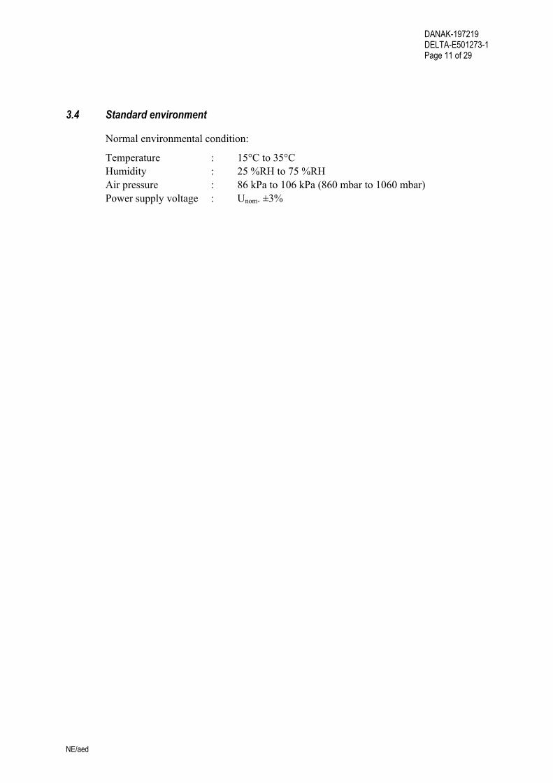
3.4 Standard environment
Normal environmental condition:
Temperature : 15°C to 35°C Humidity : 25 %RH to 75 %RH Air pressure : 86 kPa to 106 kPa (860 mbar to 1060 mbar) Power supply voltage : Unom. ±3%

DANAK-197219 DELTA-E501273-1 Page 12 of 29
NE/aed
4. Test and results
4.1 Visual inspection and performance
Specification
IACS E10, Test No. 1 and 2
Procedure
The conformance to drawings and the functional performance are demonstrated to the society surveyors present at DELTA during the type approval testing.
The functional test is also demonstrated.
Results
The conformance to drawings and the functional performance, including the functional test procedure are demonstrated to the society surveyors after the completion of the type approval testing.

DANAK-197219 DELTA-E501273-1 Page 13 of 29
NE/aed
4.2 Conducted emission (CISPR 16-1)
Specifications
CISPR 16-1 (1999-10): Specification for radio disturbance and immunity measuring apparatus and methods - Part 1: Radio disturbance and immunity measuring apparatus.
Severity and procedure
(IACS E10:2003 & IEC 60533:1999 – Power distribution zone) Frequency range : 0.01-30 MHz Limits (quasi-peak) : 0.01-0.15 MHz : 120-69 dBµV 0.15-0.50 MHz : 79 dBµV 0.50-30 MHz : 73 dBµV
The radio frequency voltage is measured at the power supply terminals of the test speci-mens, by a receiver through an artificial mains network.
The test specimens are energised and in normal operational mode during the measure-ment
Results
The conducted emissions were within the specified limits. Test record sheets of the con-ducted emission measurements are enclosed in annex 4.

DANAK-197219 DELTA-E501273-1 Page 14 of 29
NE/aed
4.3 Conducted emission (CISPR 11)
Specification
CISPR 11 (1999-08): Industrial, scientific and medical (ISM) radio-frequency equipment - Electromagnetic disturbance characteristics - Limits and methods of measurement.
Severity and procedure
Frequency range : 0.15-30 MHz Limits (quasi-peak) : 0.15-0.50 MHz : 79 dBµV quasi-peak : 66 dBµV average 0.50-30 MHz : 73 dBµV quasi-peak : 60 dBµV average
The radio frequency voltage is measured at the power supply terminals of the test speci-men, by a receiver through an artificial mains network.
The test specimen is energised and in normal operational mode during the measurement.
Results
The conducted emissions were within the specified limits. Test record sheets of the con-ducted emission measurements are enclosed in annex 4.
DANAK-197219 DELTA-E501273-1 Page 15 of 29
NE/aed
4.4 Radiated emission (CISPR 16-1)
Specifications
CISPR 16-1 (1999-10): Specification for radio disturbance and immunity measuring apparatus and methods - Part 1: Radio disturbance and immunity measuring apparatus.
Severity and procedure
(IACS E10:2003 & IEC 60533:1999 – Power distribution zone) Frequency range : 0.15-2000 MHz Limits (quasi-peak) : 0.15-30 MHz : 80-50 dBµV/m 30-100 MHz : 60-54 dBµV/m 100-2000 MHz : 54 dBµV/m, except for 156-165 MHz : 24 dBµV/m
The electric field is measured with antennas at a distance of 3 m.
The test specimens are energised and in normal operational mode during the measure-ment.
Results
The radiated emissions were within the specified limits. Test record sheets of the radi-ated emission measurements are enclosed in annex 5.
4.5 Radiated emission (CISPR 11)
Specifications
CISPR 11 (1999-08): Industrial, scientific and medical (ISM) radio-frequency equipment - Electromagnetic disturbance characteristics - Limits and methods of measurement.
Severity and procedure
Frequency range : 30-1000 MHz Limits (quasi-peak) : 30-230 MHz : 40 dBµV/m 230-1000 MHz : 47 dBµV/m
The electric field is measured with antennas at a distance of 10 m.
The test specimen is energised and in normal operational mode during the measurement.
Results
The radiated emissions were within the specified limits. Test record sheets of the radi-ated emission measurements are enclosed in annex 5.

DANAK-197219 DELTA-E501273-1 Page 16 of 29
NE/aed
4.6 High voltage
Specification
IACS E10, Test No. 10
Procedure
550 VAC, 50 Hz is applied between shorted supply terminals and earth for 1 minute. No flashover, breakdown, etc. is acceptable.
Results
Cable designation
Test condition
Test voltage[Vrms]
Duration [sec. or msec.]
Remarks (Description of reaction)
DC Power (24 VDC)
Test voltage injec-ted between shorted supply leads and protective earth
550 VAC 60 sec. No flashover or breakdown was observed during the exposure. The insulation resistance was OK after the exposure.
Note: Protection components removed prior to exposure.
4.7 Insulation resistance
Specification
IACS E10, Test No. 9
Procedure
The insulation resistance is measured between shorted supply terminals and earth with 50 VDC. The insulation resistance is to be above 10 MΩ initially, and above 1 MΩ after the low temperature, the damp heat and the high voltage exposures.
Results
Cable desig-nation
Test condition
Test voltage [Vrms]
Duration [sec]
Insulation resis-tance
[M Ohms] DC Power (24 VDC)
Before High voltage test
50 VDC 60 sec. > 1000 M Ohms
After High voltage test
50 VDC 60 sec. > 1000 M Ohms
Before Low tempera-ture test
50 VDC 60 sec. > 1000 M Ohms
After Low tempe-rature test
50 VDC 60 sec. > 1000 M Ohms
Before Damp heat test
50 VDC 60 sec. > 1000 M Ohms
After Damp heat test
50 VDC 60 sec. > 160 M Ohms
Note: Protection components removed prior to measurement.
DANAK-197219 DELTA-E501273-1 Page 17 of 29
NE/aed
4.8 Vibration
4.8.1 Resonance search
Specifications
IEC 60068-2-6 (1985), Test Fc: Vibration (sinusoidal).
Severity and procedure
Frequency range : 2-100 Hz Frequency/amplitude : 2-25 Hz : ±1.6 mm 25-100 Hz : ±4.0 g Sweep rate : Max. 1 octave/min. Number of axes : 3 mutually perpendicular
The test specimens are de-energised during the exposure.
During the resonance search, the resonance frequencies are determined by means of stroboscopic light with slow-motion facility and accelerometer measurements of the am-plification factors (Q).
Resonance frequencies with an amplification factor above 2 are recorded.
Results
No amplification factors above 2 were recorded.
DANAK-197219 DELTA-E501273-1 Page 18 of 29
NE/aed
4.8.2 Endurance vibration
The sinusoidal vibration test according to IACS E10 is replaced by random vibration test according to Certification Notes No. 2.4, issued May 1995 by DNV.
This random vibration test will cover the requirements of the sinusoidal vibration test according to IACS E10.
Specification
IEC 60068-2-64 (1993), Test Fh: Vibration, broadband random (digital control).
Severity and procedure
Frequency range : 2-100 Hz Acceleration spectral : 2-25 Hz : +12 dB/octave Density : 25-100 Hz : 0.2 g2/Hz Total RMS level : 4.0 g Duration : 150 minutes per axis Number of axes : 3 mutually perpendicular
The test specimens are energised and in normal operational mode during the exposures. A functional test is performed after the exposure in each axis.
A visual inspection is performed after the exposure.
Results
No malfunction was observed during the exposure and the function of the test specimens was OK after the exposure in each axis.
No damage was observed after the exposures.
DANAK-197219 DELTA-E501273-1 Page 19 of 29
NE/aed
4.9 Power supply variations
Specifications
IACS E10, Test No. 4 IEC 60945, Section 5.2.2
Procedure (24 VDC supplied)
Unom. = Nominal supply voltage = 24 VDC
Exposures, each with a duration of 15 minutes, are performed at the following supply voltages:
U1 = Un+30% = 31.2 VDC U2 = Un-25% = 18.0 VDC
The test specimens are observed during the exposures, and a functional test is performed at the end of each exposure.
An additional power supply variations test is performed as part of the functional test dur-ing the low temperature and the dry heat test profiles.
Results
No malfunction was observed during the exposure, and the function of the test speci-mens was OK after the exposure.
4.10 Power supply failure
Specifications
IACS E10, Test No. 3
Procedure
The power supply is interrupted 3 times within 5 minutes with a break time of 60 sec-onds.
Normal power-up procedure is to be obtained after each power break.
Results
No malfunction was observed during the exposure, and the function of the test speci-mens was OK after each exposure.

DANAK-197219 DELTA-E501273-1 Page 20 of 29
NE/aed
4.11 Conducted low frequency interference
Specifications
IEC 61000-4-16 (1998-01): Test for immunity to conducted, common mode disturbances in the frequency range 0 Hz to 150 kHz.
Severity and procedure
Frequency range : 0.05 - 10 kHz Amplitude (DC-supplied) : 0.05 - 10 kHz : 10% of Unom. / min.3 Vrms
Maximum applied power : 2.0 W
The impedance of the test generator is less than 1 Ω.
The test signal is superimposed on the power supply lines via a coupling transformer.
The test specimens are energised and in normal operational mode during the exposure. The test specimens are observed during the exposure, and a functional test is performed after the exposure.
Results
No malfunction was observed during the exposure, and the function of the test speci-mens was OK after the exposure.
DANAK-197219 DELTA-E501273-1 Page 21 of 29
NE/aed
4.12 Conducted radio frequency interference
Specifications
IEC 61000-4-6 (2001-04), Ed. 1.1: Testing and measurement techniques - Immunity to conducted disturbances, induced by radio-frequency fields.
Severity and procedure
Frequency range : 150 kHz - 80 MHz Amplitude : 0.15-80 MHz : 10 Vrms Modulation : 80% AM, 400 Hz sine wave 80% AM, 1 kHz sine wave
The test specimen is supplied with power via a coupling/decoupling network.
The test signal is coupled to the power lines and signal lines via coupling networks. The coupling impedance is 150 Ω.
The test specimens are energised and in normal operational mode during the exposure. The test specimens are observed during the exposure, and a functional test is performed after the exposure.
Results
No malfunction was observed during the exposure, and the function of the test speci-mens was OK after the exposure.
DANAK-197219 DELTA-E501273-1 Page 22 of 29
NE/aed
4.13 Radiated radio frequency interference
Specifications
IEC 61000-4-3 (2002-03): Testing and measurement techniques - Radiated, radio-frequency, electromagnetic field immunity test. Severity and procedure Frequency range : 80-2000 MHz Field strength : 10 V/m Modulation : 80% AM, 400 Hz sine wave : 80% AM, 1 kHz sine wave
The test is performed in a semi-anechoic room. The field is generated using linearly po-larised broadband antennas.
The test specimens are energised and in normal operational mode during the exposure. The test specimens are observed during the exposure, and a functional test is performed after the exposure.
Results
No malfunction was observed during the exposure, and the function of the test speci-mens was OK after the exposure.

DANAK-197219 DELTA-E501273-1 Page 23 of 29
NE/aed
4.14 Surge voltage
Specification
IEC 61000-4-5 (2001-04) Ed. 1.1: Testing and measurement techniques - Surge immu-nity test.
Severity and procedure
Amplitude AC power lines : 1 & 2 kV line-to-earth, 0.5 & 1 kV line-to-line Amplitude signal lines : 1 kV line-to-earth (lines >30 m) Voltage rise time : 1.2 µs (open circuit) Voltage decay time : 50 µs (open circuit)
The impedance of the test generator is 2 Ω for line-to-line coupling and 12 Ω for line-to-earth coupling.
The impedance of the test generator is 2 Ω, for exposures on shielded signal lines.
The test specimens are supplied with power via a transient coupling network.
The test specimens are energised and in normal operational mode during the exposure. The test specimens are observed during the exposure, and a functional test is performed after the exposure.
Results
No malfunction was observed during the exposure, and the function of the test speci-mens was OK after the exposure.

DANAK-197219 DELTA-E501273-1 Page 24 of 29
NE/aed
4.15 Electrostatic discharge
Specifications
IEC 61000-4-2 (2001-04) Ed. 1.2: Testing and measurement techniques - Electrostatic discharge immunity test.
Severity and procedure
Air discharge : 2, 4 and 8 kV Contact discharge : 2, 4 and 6 kV Energy storage capacitance : 150 pF Discharge resistance : 330 Ω Polarity : + and - Number of discharges : 10 per polarity at each test point
The discharges are applied only to such points and surfaces of the test specimen, which are accessible to personnel during normal use.
Contact discharges are applied to conductive surfaces and coupling planes, and air dis-charges are applied to insulating surfaces.
The test specimens are energised and in normal operational mode during the exposure. The test specimens are observed during the exposure, and a functional test is performed after the exposure.
Results
No malfunction was observed during the exposure, and the function of the test speci-mens was OK after the exposure.
DANAK-197219 DELTA-E501273-1 Page 25 of 29
NE/aed
4.16 Fast transients (burst)
Specifications
IEC 61000-4-4 (1995-01): Testing and measurement techniques - Section 4: Electrical fast transient/burst immunity test, Amendment 1 (2000-11), Amendment 2 (2001-07).
Severity and procedure
Amplitude : 2 kV on power lines 1 kV on signal lines Pulse rise time : 5 ns Pulse duration : 50 ns Generator impedance : 50 Ω Repetition rate : 5 kHz Burst duration : 15 ms Burst period time : 300 ms
The test specimens are supplied with power via a transient coupling network. The test signal is successively coupled to each power line and protective earth with reference to the ground plane.
The test signal is injected on the signal lines using a capacitive coupling clamp. The clamp is successively used on selected signal cables.
The test signal is injected on the power lines for 5 minutes, using each coupling mode and each polarity, and then on the signal lines for 5 minutes using each polarity.
The test specimens are energised and in normal operational mode during the exposure. The test specimens are observed during the exposure and a functional test is performed after the exposure.
Results
No malfunction was observed during the exposure, and the function of the test speci-mens was OK after the exposure.
DANAK-197219 DELTA-E501273-1 Page 26 of 29
NE/aed
4.17 1 MHz burst
Specifications
IEC 60255-22-1 (1988):Electrical disturbance tests for measuring relays and protection equipment. Part 1: 1 MHz burst disturbance tests.
Severity and procedure
Amplitude : 1 kV DM on power ports and I/O ports 2.5 kV CM on power ports and I/O ports 1 kV CM on communication ports Frequency : 1 MHz Source impedance . 200 Ohm Rise time : 75 ns Repetition frequency : 400 Hz
The test specimen is energised and in normal operational mode during the exposure. The test specimen is observed during the exposure and a functional test is performed after the exposure.
Results
No malfunction was observed during the exposure, and the function of the test speci-mens was OK after the exposure.
DANAK-197219 DELTA-E501273-1 Page 27 of 29
NE/aed
4.18 Dry heat
Specification
IEC 60068-2-2 (1974), Test Bd: Dry heat for heat-dissipating specimen with gradual change of temperature, Amendment 1 (1993), Amendment 2 (1994).
Severity and procedure
The following two exposures are performed:
1. Temperature : 55°C Duration : 16 hours Humidity : Below 50 %RH
2. Temperature : 70°C Duration : 2 hours Humidity : Below 50 %RH
The test specimens are energised and in normal operating condition during the exposure. During the last hour of the exposure, a functional test is performed.
After recovery the functional test is repeated in standard environment.
Results
No malfunction was observed during the exposure and the function of the test specimen was OK during the last hour of the exposure and after recovery.
DANAK-197219 DELTA-E501273-1 Page 28 of 29
NE/aed
4.19 Low temperature (cold)
Specifications
IEC 60068-2-1 (1990), Test Ad: Cold for heat-dissipating specimen with gradual change of temperature, Amendment 1 (1993), Amendment 2 (1994).
Severity and procedure
The following two exposures are performed:
1. Temperature : -15°C Duration : 16 hours
2. Temperature : -25°C Duration : 2 hours
The test specimens are de-energised during the exposure. However, during the last hour of the exposure the test specimen is energised and a functional test is performed. After recovery a functional test and an insulation resistance test are performed in standard en-vironment.
Results
No malfunction was observed during the exposure and the function of the test specimen was OK during the last hour of the exposure and after recovery.

DANAK-197219 DELTA-E501273-1 Page 29 of 29
NE/aed
4.20 Damp heat, cyclic
Test specification
IEC 60068-2-30 (1980), Test Db: Damp heat cyclic (12 + 12 hours' cycle), Variant 1, Amendment 1 (1985).
Severity and procedure
Lower temperature : 25°C Humidity at lower temperature : >95 %RH Upper temperature : 55°C Humidity at upper temperature : 93 %RH Number of cycles : 2
During the first cycle, the test specimens are energised and in normal operational mode. A functional test is performed during the first 2 hours of the 55°C phase.
During the second cycle, the test specimens are de-energised. However, during the last 2 hours of the second 55°C phase the test specimens are energised and a functional test is performed.
After recovery the test specimens are energised and a functional test and an insulation resistance test are performed in standard environment.
Results
No malfunction was observed during the exposure, and the function of the test specimen was OK during the first and second cycle at 55°C and 93 %RH, and after recovery.
No corrosion attack was observed after the exposure.

DANAK-197219 DELTA-E501273-1
NE/aed
Annex 1
List of instruments
(2 pages)

DANAK-197219 DELTA-E501273-1
NE/aed
List of instruments NO. DESCRIPTION MANUFACTURER TYPE NO. 22631 VIBRATION CONTROLLER SIGNAL STAR VECTOR U2 Sys 5144 ACC. 91 ACCELEROMETER BRUEL & KJÆR 4371 ACC. 93 ACCELEROMETER BRUEL & KJÆR 4371 ACC.71A ACCELEROMETER BRUEL & KJÆR 4393 ACC. 72 ACCELEROMETER BRUEL & KJÆR 4393 22630 ACCELEROMETER PREAMPLIFIER BRUEL & KJÆR 2692 22589 ACCELEROMETER PREAMPLIFIER BRUEL & KJÆR 2626 22601 ELECTRONIC VOLTMETER HEWLETT-PACKARD 34401A 22591 OSCILLOSCOPE KENWOOD CS-1025 Y221 ELECTRODYNAMIC SHAKER LING DYNAMIC SYS. V 875-440T U2501 SWITCHING POWER AMPLIFIER LING DYNAMIC SYS. SPA 50/30KCE EVFGT-27 CLIMATIC TEST CHAMBER DELTA VKF10 EVFGT-28 CLIMATIC TEST CHAMBER DELTA VF10 29223 CURRENT PROBE SINGER 91550-4 29342 REFLECTOMETER COUPLER, 600-4200 MHz ROHDE & SCHWARZ ZPD 29347 RF GENERATOR , 10 kHz-1 GHz MARCONI 2022 29461 ARTIFICIAL MAINS NETWORK ROHDE & SCHWARZ ESH2/Z5 29680 IMPULSE VOLTAGE LIMITER ROHDE & SCHWARZ ESH3/Z2 29691 0.01 - 20 GHz. SYNTH. SWEEPER HEWLETT-PACKARD 83620A 29694 1-12 GHz. HORN ANTENNA. LOGIMETRICS AN 8200 F 29703 LF POWER AMPLIFIER BRUEL & KJÆR 2708 29754 RF POWER ATTENUATOR, 50 OHM, 6 dB,
150 W NARDA 769-6
29781 DIGITAL MULTIMETER W. HPIB HEWLETT-PACKARD 34401A 29786 HIGH POWER RF AMPLIFIER, 80-1000 MHz AMPLIFIER RESEARCH 500W1000M5 29797 BILOG ANTENNA, 30-1000 MHz CHASE ELECTRICS LTD CBL 6111A 29815 3-LINE CDN NETWORK,
IEC 61000-4-6 MEB M3
29749 SHIELD-LINE CDN NETWORK, IEC 61000-4-6
DELTA EMC DEPT. SHIELD LINE CDN
29827 ELECTRONIC SURGE GENERATOR EM TEST VCS 500 29832 DIFFERENTIAL HIGH VOLTAGE PROBE,
DC-25 MHz TEKTRONIX P5200
29838 ESD GENERATOR, AIR AND CONTACT DIS-CHARGE
KEYTEK MZ-15EC
29844 -40 dBc VOLTAGE SAMPLER, DC-100 MHz DELTA EMC DEPT. SAMPLER VER. 2
29846 RF GENERATOR, 9 kHz-2.4 GHz MARCONI 2024 29861 EMI-SOFTWARE Ver. 1.60 ROHDE & SCHWARZ ES-K1, PART:
1026.6790.02 29865 CAPACITIVE COUPLING CLAMP DELTA EMC IEC 1000-4-4
DANAK-197219 DELTA-E501273-1
NE/aed
NO. DESCRIPTION MANUFACTURER TYPE NO. 29866 LF INJECTION TRAFO, 6 x 6 TURNS KNUD OVERGAARD 14311 29880 CURRENT PROBE AMPLIFIER FOR 29907
AND 29707 TEKTRONIX AM503B
29884 PULSE / FUNCTION GENERATOR, 50 MHz
WAVETEK 81
29904 BROADBAND POWER AMPLIFIER, 10 kHz-250 MHz, 75 W
AMPLIFIER RESEARCH 75A250
29906 15 MHz FUNCTION / ARBITRARY WAVE GENERATOR
HEWLETT-PACKARD 33120A
29907 ACTIVE CURRENT PROBE HEAD FOR 29880 TEKTRONIX A6302 29913 ELECTRICAL FAST TRANSIENT (BURST)
GENERATOR EM TEST EFT 500
29915 DC COUPLED POWER AMPLIFIER / POWER SUPPLY
HEWLETT-PACKARD 467A
29916 AUTOMATIC TEST RECEIVER, 9 kHz-2.75 GHz
ROHDE & SCHWARZ ESCS 30 1102.4500.30
29936 SAMPLING OSCILLOSCOPE, 100 MHz, 500 MS/s
TEKTRONIX TDS 340A
29967 COAX RF DIODE DETECTOR, NEG. OUT-PUT, ROOM 5
HEWLETT-PACKARD 8471D
29975 DIGITAL MULTIMETER w. GPIB HEWLETT-PACKARD 34401A 29984 RF POWER AMPLIFIER, 0.8-2.2 GHz, 200W MILMEGA AS0822-200 29985 BILOG ANTENNA 26-2000 MHz SCHAFFNER/CHASE 6140A 49002 SINGLE CHANNEL POWER METER DIS-
PLAY UNIT ROHDE & SCHWARZ NRVS
49003 THERMAL POWER SENSOR, DC-18 GHz ROHDE & SCHWARZ NRV-Z51 49024 COAX RF DIODE DETECTOR, NEG. OUT-
PUT, CS TEST HEWLETT-PACKARD 8471D
49034 "CABLE#42", 3 M, 50 OHM COAX CABLE, N-N (STRAIGHT)
CELLFLEX
29332 ACTIVE LOOP ANTENNA ROHDE & SCHWARZ HFH-Z2 43028 MEGGER AVO INTERNATIONAL BM 80 30344 HIGH VOLTAGE APPARATUS WILLY NIELSEN W5 49007 HFD-RELAY TESTER / 1 MHz BURST HAEFELY P3

DANAK-197219 DELTA-E501273-1
NE/aed
Annex 2
Photos
(9 pages)

DANAK-197219 DELTA-E501273-1
NE/aed
PHOTO 1. Conducted low frequency interference.
PHOTO 2. Conducted radio frequency interference.

DANAK-197219 DELTA-E501273-1
NE/aed
PHOTO 3. Conducted radio frequency interference.
PHOTO 4. Electrostatic discharge. (e.g. S6500).
DANAK-197219 DELTA-E501273-1
NE/aed
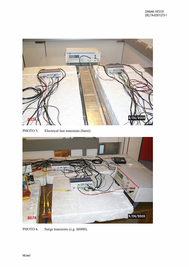
PHOTO 5. Electrical fast transients (burst).
PHOTO 6. Surge transients (e.g. S6000).

DANAK-197219 DELTA-E501273-1
NE/aed
PHOTO 7. Conducted emission. (e.g. CISPR 16-1).
PHOTO 8. Radiated emission (3 m).

DANAK-197219 DELTA-E501273-1
NE/aed
PHOTO 9. Radiated emission (3 m).
PHOTO 10. Radiated emission (3 m).
DANAK-197219 DELTA-E501273-1
NE/aed
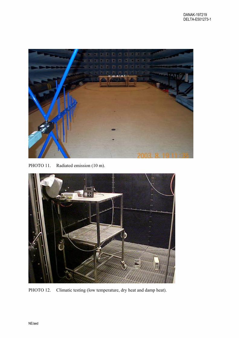
PHOTO 11. Radiated emission (10 m).
PHOTO 12. Climatic testing (low temperature, dry heat and damp heat).

DANAK-197219 DELTA-E501273-1
NE/aed
PHOTO 13. Vibration testing (resonance search), e.g. S6000.
PHOTO 14. Vibration testing (endurance).
DANAK-197219 DELTA-E501273-1
NE/aed
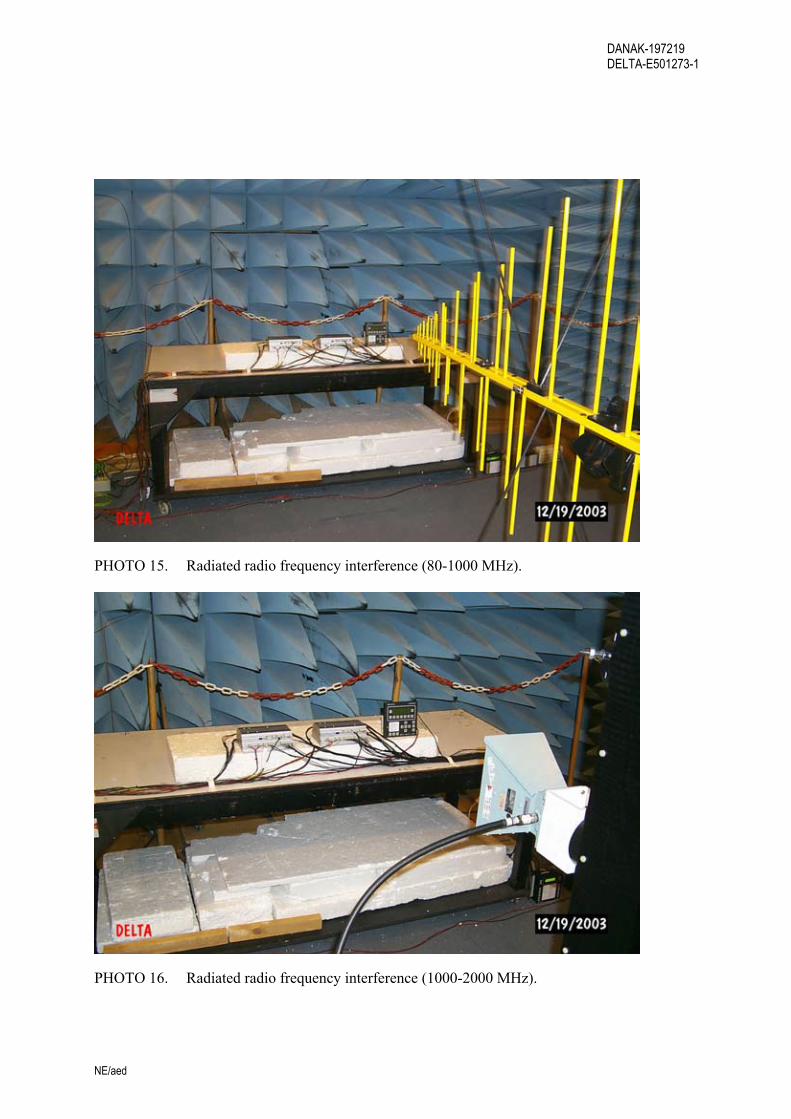
PHOTO 15. Radiated radio frequency interference (80-1000 MHz).
PHOTO 16. Radiated radio frequency interference (1000-2000 MHz).

DANAK-197219 DELTA-E501273-1
NE/aed
PHOTO 17. 1 MHz burst (e.g. S6000).
PHOTO 18. 1 MHz burst (e.g. S6000).
DANAK-197219 DELTA-E501273-1
NE/aed
Annex 3
Test set-up, system briefing and functional test procedure (from Selco A/S )
(8 pages)

DANAK-197219 DELTA-E501273-1
NE/aed
Test set-up
SIGMA S6000 EUT 2.1
SIGMA S6100 EUT 2.2
SIGMA S6500
EUT 2.3
M3000 AUX 2.6
M4100 AUX 2.5
Simulator box AUX 2.7
M4100 AUX 2.4
Relay status indicator
24 VDC
24 VDC
24 VDC
All cables unshielded
400 VAC sense
400 VAC sense
CAN
SYNC CT
Protection
A. outp.
Relay & C/B
I/O
Volt/Speed toggle
Par. L.
A. outp.
Relay & C/B
Manual
DANAK-197219 DELTA-E501273-1
NE/aed
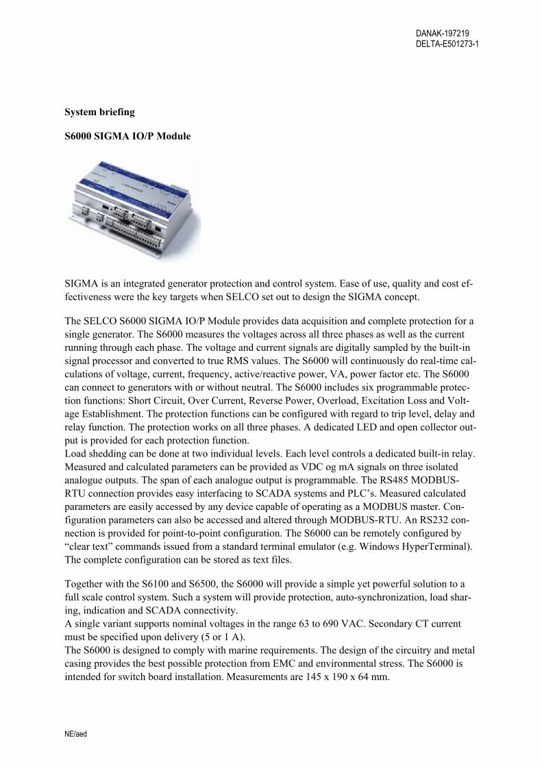
System briefing
S6000 SIGMA IO/P Module
SIGMA is an integrated generator protection and control system. Ease of use, quality and cost ef-fectiveness were the key targets when SELCO set out to design the SIGMA concept.
The SELCO S6000 SIGMA IO/P Module provides data acquisition and complete protection for a single generator. The S6000 measures the voltages across all three phases as well as the current running through each phase. The voltage and current signals are digitally sampled by the built-in signal processor and converted to true RMS values. The S6000 will continuously do real-time cal-culations of voltage, current, frequency, active/reactive power, VA, power factor etc. The S6000 can connect to generators with or without neutral. The S6000 includes six programmable protec-tion functions: Short Circuit, Over Current, Reverse Power, Overload, Excitation Loss and Volt-age Establishment. The protection functions can be configured with regard to trip level, delay and relay function. The protection works on all three phases. A dedicated LED and open collector out-put is provided for each protection function. Load shedding can be done at two individual levels. Each level controls a dedicated built-in relay. Measured and calculated parameters can be provided as VDC og mA signals on three isolated analogue outputs. The span of each analogue output is programmable. The RS485 MODBUS-RTU connection provides easy interfacing to SCADA systems and PLC’s. Measured calculated parameters are easily accessed by any device capable of operating as a MODBUS master. Con-figuration parameters can also be accessed and altered through MODBUS-RTU. An RS232 con-nection is provided for point-to-point configuration. The S6000 can be remotely configured by “clear text” commands issued from a standard terminal emulator (e.g. Windows HyperTerminal). The complete configuration can be stored as text files.
Together with the S6100 and S6500, the S6000 will provide a simple yet powerful solution to a full scale control system. Such a system will provide protection, auto-synchronization, load shar-ing, indication and SCADA connectivity. A single variant supports nominal voltages in the range 63 to 690 VAC. Secondary CT current must be specified upon delivery (5 or 1 A). The S6000 is designed to comply with marine requirements. The design of the circuitry and metal casing provides the best possible protection from EMC and environmental stress. The S6000 is intended for switch board installation. Measurements are 145 x 190 x 64 mm.

DANAK-197219 DELTA-E501273-1
NE/aed
S6100 SIGMA S/LS Module
SIGMA is an integrated generator protection and control system. Ease of use, quality and cost ef-fectiveness were the key targets when SELCO set out to design the SIGMA concept.
The SELCO S6100 SIGMA S/LS Module provides frequency control, voltage control, automatic synchronization and active/reactive load sharing. The S6100 has dedicated interfaces for both conventional and electronic governors and automatic voltage regulators. Manual control is also possible though external push buttons. The S6100 reads generators parameters from the S6000 IO/P module (connected through the CAN bus). The S6100 will also measure the Bus bar volt-ages across all three phases. The bus bar voltage measurements are digitally sampled by the built-in signal processor and converted to true RMS values. The S6100 will continuously do real-time calculations of derived parameters. The S6100 can connect to generators with or without neutral. The S6100 includes voltage control, frequency control, voltage matching, automatic or manual synchronisation and automatic or man-ual active/reactive load sharing. The control algorithms are based on three phase measurements. Built-in relays are provided for control of conventional governors and AVR’s. Isolated analogue outputs are provided for control of electronic governors and AVR’s. The S6100 will work with or without droop. The S6100 can operate in parallel with the SELCO T4400 or T4800 load sharers. The RS485 MODBUS-RTU connection provides easy interfacing to SCADA systems and PLC’s. Measured calculated parameters are easily accessed by any device capable of operating as a MODBUS master. Configuration parameters can also be accessed and altered through MODBUS-RTU. An RS232 connection is provided for point-to-point configuration. The S6000 can be remotely configured by “clear text” commands issued from a standard terminal emulator (e.g. Windows HyperTerminal). The complete configuration can be stored as text files. Together with the S6000 and S6500, the S6100 will provide a simple yet powerful solution to a full scale control system. Such a system will provide protection, auto-synchronization, load shar-ing, indication and SCADA connectivity. A single variant supports nominal voltages in the range 63 to 690 VAC. Secondary CT current must be specified upon delivery (5 or 1 A). The S6100 is designed to comply with marine requirements. The design of the circuitry and metal casing pro-vides the best possible protection from EMC and environmental stress. The S6100 is intended for switch board installation. Measurements are 145 x 190 x 64 mm.
DANAK-197219 DELTA-E501273-1
NE/aed
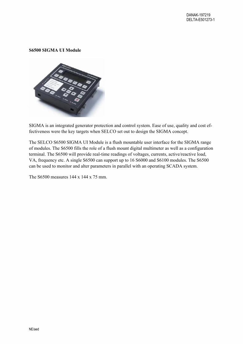
S6500 SIGMA UI Module
SIGMA is an integrated generator protection and control system. Ease of use, quality and cost ef-fectiveness were the key targets when SELCO set out to design the SIGMA concept.
The SELCO S6500 SIGMA UI Module is a flush mountable user interface for the SIGMA range of modules. The S6500 fills the role of a flush mount digital multimeter as well as a configuration terminal. The S6500 will provide real-time readings of voltages, currents, active/reactive load, VA, frequency etc. A single S6500 can support up to 16 S6000 and S6100 modules. The S6500 can be used to monitor and alter parameters in parallel with an operating SCADA system.
The S6500 measures 144 x 144 x 75 mm.

DANAK-197219 DELTA-E501273-1
NE/aed
Functional test procedure
General performance verification is performed as follows:
1. Change to “VOLT” or “AMP” mode
2. S6500 “MENU”
3. Select “GENERATOR MODULE”
4. Select “SIGMA IO/P”->”PROTECTION”->”SHORT CIRCUIT”
5. Change “TRIP LEVEL” 0% - press “YES”
6. “C/B TRIP” & “SC” activated on S6000 & M4100
7. Change “TRIP LEVEL” 120% - press “YES”
8. Press “C/B reset” on simulator box
9. “C/B TRIP” & “SC” de-activated on S6000
10. Reset M4100’s
11. Select “SIGMA IO/P”->”PROTECTION”->”OVER CURRENT”
12. Change “TRIP LEVEL” 0% - press “YES”
13. “C/B TRIP” & “OC” activated on S6000 & M4100
14. Change “TRIP LEVEL” 100% - press “YES”
15. Press “C/B reset” on simulator box
16. “C/B TRIP” & “OC” de-activated on S6000
17. Reset M4100’s
18. Select “SIGMA IO/P”->”PROTECTION”->”OVER LOAD”
19. Change “TRIP LEVEL” 0% - press “YES”
20. “C/B TRIP” & “OL” activated on S6000 & M4100
21. Change “TRIP LEVEL” 100% - press “YES”
22. Press “C/B reset” on simulator box
23. “C/B TRIP” & “OL” de-activated on S6000

DANAK-197219 DELTA-E501273-1
NE/aed
24. Reset M4100’s
25. Select “SIGMA IO/P”->”PROTECTION”->”REVERSE POWER”
26. Change “TRIP LEVEL” 0% - press “YES”
27. “C/B TRIP” & “RP” activated on S6000 & M4100
28. Change “TRIP LEVEL” -7% - press “YES”
29. Press “C/B reset” on simulator box
30. “C/B TRIP” & “RP” de-activated on S6000
31. Reset M4100’s
32. Select “SIGMA IO/P”->”PROTECTION”->”EXCITATION LOSS”
33. Change “TRIP LEVEL” 0% - press “YES”
34. “C/B TRIP” & “EL” activated on S6000 & M4100
35. Change “TRIP LEVEL” -5% - press “YES”
36. Press “C/B reset” on simulator box
37. “C/B TRIP” & “EL” de-activated on S6000
38. Reset M4100’s
39. Select “SIGMA IO/P”->”PROTECTION”->”VOLTAGE ESTABLISH”
40. Change “LOWER TRIP LEVEL” 100% - press “YES”
41. “C/B TRIP” & “VE” activated on S6000 & M4100
42. Change “LOWER TRIP LEVEL” 80% - press “YES”
43. Press “C/B reset” on simulator box
44. “C/B TRIP” & “VE” de-activated on S6000
45. Reset M4100’s
46. Select “SIGMA IO/P”->”PROTECTION”->”NONE ESSENTIALS 1”
47. Change “TRIP LEVEL” 0% - press “YES”
48. “NE1” activated on S6000 & M4100
DANAK-197219 DELTA-E501273-1
NE/aed
49. Change “TRIP LEVEL” 100% - press “YES”
50. Press “NE reset” on simulator box
51. “NE1” de-activated on S6000
52. Reset M4100’s
53. Select “SIGMA IO/P”->”PROTECTION”->”NONE ESSENTIALS 2”
54. Change “TRIP LEVEL” 0% - press “YES”
55. “NE2” activated on S6000 & M4100
56. Change “TRIP LEVEL” 100% - press “YES”
57. Press “NE reset” on simulator box
58. “NE2” de-activated on S6000
59. Reset M4100’s
60. “C/B state” of simulator box “OFF” -> “C/B” LED’s “OFF”
61. Interchange phase S & T -> “PHASE” LED’s “OFF” on S6000 & S6100
62. Re-establish phase S & T -> “PHASE” LED’s “ON” on S6000 & S6100
63. Press “UNLOAD” on simulator box -> “UNLOAD” LED “ON” on S6100
64. Press “C/B CLOSE BLOCK” on simulator box -> “C/B BLOCK” LED “ON” on S6100
65. “C/B state” of simulator box “ON” -> “C/B” LED’s “ON”
66. Press “SPEED INCR” on simulator box -> “SPEED” volt/amp on M3000 increases
67. Press “SPEED DECR” on simulator box -> “SPEED” volt/amp on M3000 decreases
68. Set “SPEED” level to 4,5V/12 mA
69. Press “VOLT INCR” on simulator box -> “VOLT” volt/amp on M3000 increases
70. Press “VOLT DECR” on simulator box -> “VOLT” volt/amp on M3000 decreases
71. Set “VOLT” level to 4,5V/12 mA
72. Change to “RELAY” mode
73. S6500 “MENU”

DANAK-197219 DELTA-E501273-1
NE/aed
74. Select “GENERATOR MODULE”
75. Select “SIGMA S/LS”->”SYSTEM”->”GOVERNOR”->”CONVENTIONAL->”YES”
76. Activate “DECR” or “INCR” on simulator box -> “SPEED” or “VOLT” relay’s toggle
77. Re-establish “VOLT” or “AMP” mode
78. Remove 24 VDC from “BACKUP SUPPLY” from S6000, S6100 & S6500
79. “ALARM” LED’s & “ALARM” relay’s of S6000 & S6100 activated
80. “POWER 2” LED on S6500 “OFF”
81. Re-establish 24 VDC supply -> Alarms of & power LED’s “ON”
82. Reset M4100’s
DANAK-197219 DELTA-E501273-1
NE/aed
Annex 4
Test record sheets – Conducted emissions
(24 pages)
DANAK-197219 DELTA-E501273-1
NE/aed
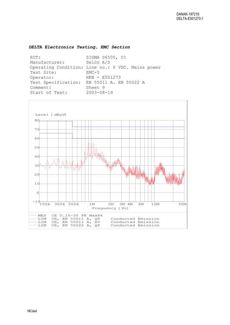
DELTA Electronics Testing, EMC Section EUT: SIGMA S6500, UI Manufacturer: Selco A/S Operating Condition: Line no.: 0 VDC. Mains power Test Site: EMC-5 Operator: HEN - E501273 Test Specification: EN 55011 A. EN 55022 A Comment: Sheet 9 Start of Test: 2003-08-19
-10
0
10
20
30
40
50
60
70
80
Level [dBµV]
150k 300k 500k 1M 2M 3M 4M 6M 10M 30MFrequency [Hz]
MES CE 0.15-30 PK MaxPk LIM CE, EN 55011 A, QP Conducted EmissionLIM CE, EN 55011 A, AV Conducted EmissionLIM CE, EN 55022 A, QP Conducted Emission

DANAK-197219 DELTA-E501273-1
NE/aed
DELTA Electronics Testing, EMC Section EUT: SIGMA S6500, UI Manufacturer: Selco A/S Operating Condition: Line no.: +24 VDC. Mains power Test Site: EMC-5 Operator: HEN - E501273 Test Specification: EN 55011 A. EN 55022 A Comment: Sheet 10 Start of Test: 2003-08-19
-10
0
10
20
30
40
50
60
70
80
Level [dBµV]
150k 300k 500k 1M 2M 3M 4M 6M 10M 30MFrequency [Hz]
MES CE 0.15-30 PK MaxPk LIM CE, EN 55011 A, QP Conducted EmissionLIM CE, EN 55011 A, AV Conducted EmissionLIM CE, EN 55022 A, QP Conducted Emission

DANAK-197219 DELTA-E501273-1
NE/aed
DELTA Electronics Testing, EMC Section EUT: SIGMA S6500, UI Manufacturer: Selco A/S Operating Condition: Line no.: +24 VDC. Backup power Test Site: EMC-5 Operator: HEN - E501273 Test Specification: EN 55011 A. EN 55022 A Comment: Sheet 11 Start of Test: 2003-08-19
-10
0
10
20
30
40
50
60
70
80
Level [dBµV]
150k 300k 500k 1M 2M 3M 4M 6M 10M 30MFrequency [Hz]
MES CE 0.15-30 PK MaxPk LIM CE, EN 55011 A, QP Conducted EmissionLIM CE, EN 55011 A, AV Conducted EmissionLIM CE, EN 55022 A, QP Conducted Emission
DANAK-197219 DELTA-E501273-1
NE/aed
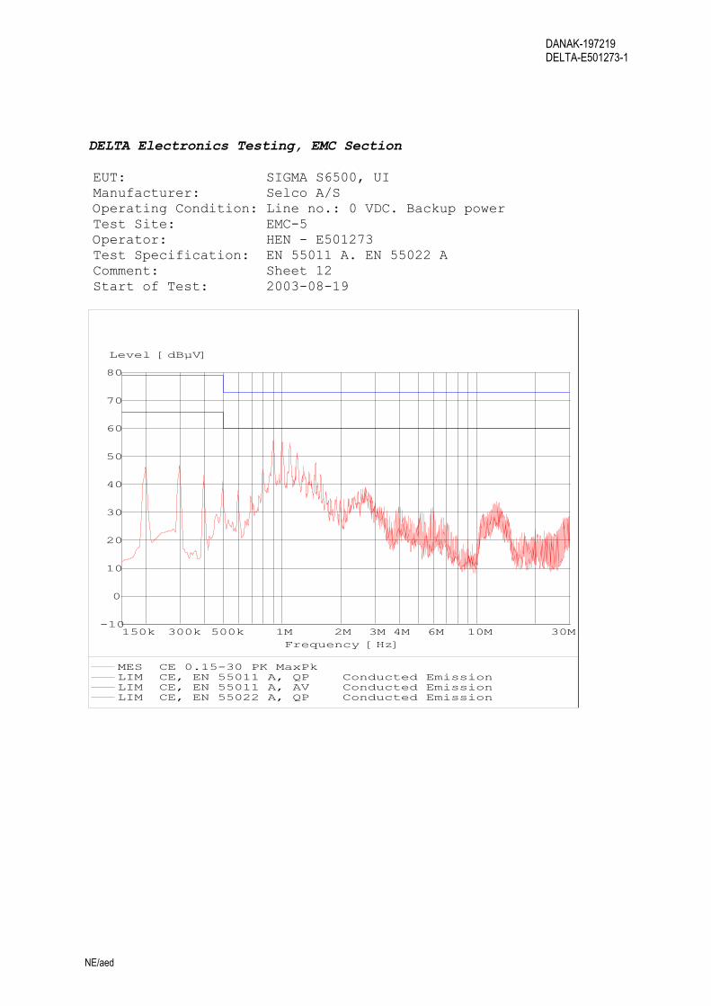
DELTA Electronics Testing, EMC Section EUT: SIGMA S6500, UI Manufacturer: Selco A/S Operating Condition: Line no.: 0 VDC. Backup power Test Site: EMC-5 Operator: HEN - E501273 Test Specification: EN 55011 A. EN 55022 A Comment: Sheet 12 Start of Test: 2003-08-19
-10
0
10
20
30
40
50
60
70
80
Level [dBµV]
150k 300k 500k 1M 2M 3M 4M 6M 10M 30MFrequency [Hz]
MES CE 0.15-30 PK MaxPk LIM CE, EN 55011 A, QP Conducted EmissionLIM CE, EN 55011 A, AV Conducted EmissionLIM CE, EN 55022 A, QP Conducted Emission

DANAK-197219 DELTA-E501273-1
NE/aed
DELTA Electronics Testing, EMC Section EUT: SIGMA S6100, S/LS Manufacturer: Selco A/S Operating Condition: Line no.: 0 VDC. Mains power Test Site: EMC-5 Operator: HEN - E501273 Test Specification: EN 55011 A. EN 55022 A Comment: Sheet 13 Start of Test: 2003-08-19
-10
0
10
20
30
40
50
60
70
80
Level [dBµV]
150k 300k 500k 1M 2M 3M 4M 6M 10M 30MFrequency [Hz]
MES CE 0.15-30 PK MaxPk MES CE 0.15-30 AV Avg LIM CE, EN 55011 A, QP Conducted EmissionLIM CE, EN 55011 A, AV Conducted Emission
DANAK-197219 DELTA-E501273-1
NE/aed
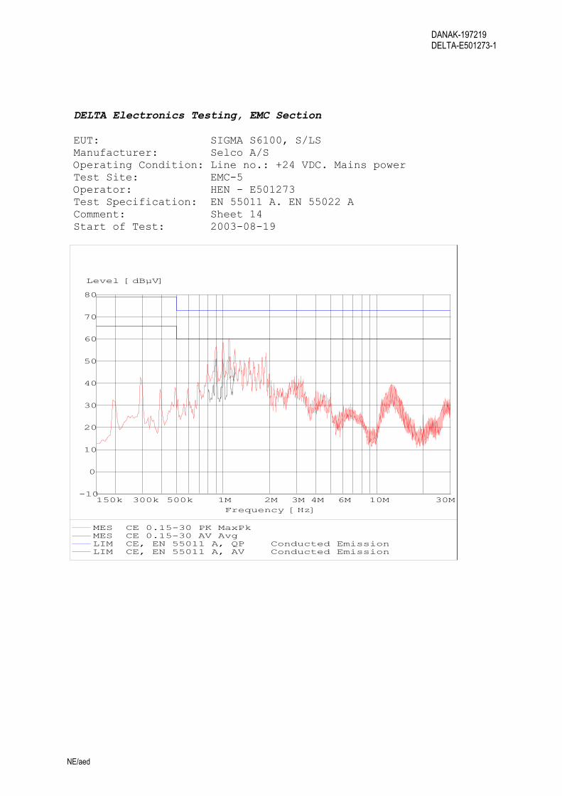
DELTA Electronics Testing, EMC Section EUT: SIGMA S6100, S/LS Manufacturer: Selco A/S Operating Condition: Line no.: +24 VDC. Mains power Test Site: EMC-5 Operator: HEN - E501273 Test Specification: EN 55011 A. EN 55022 A Comment: Sheet 14 Start of Test: 2003-08-19
-10
0
10
20
30
40
50
60
70
80
Level [dBµV]
150k 300k 500k 1M 2M 3M 4M 6M 10M 30MFrequency [Hz]
MES CE 0.15-30 PK MaxPk MES CE 0.15-30 AV Avg LIM CE, EN 55011 A, QP Conducted EmissionLIM CE, EN 55011 A, AV Conducted Emission

DANAK-197219 DELTA-E501273-1
NE/aed
DELTA Electronics Testing, EMC Section EUT: SIGMA S6100, S/LS Manufacturer: Selco A/S Operating Condition: Line no.: +24 VDC. Backup power Test Site: EMC-5 Operator: HEN - E501273 Test Specification: EN 55011 A. EN 55022 A Comment: Sheet 15 Start of Test: 2003-08-19
-10
0
10
20
30
40
50
60
70
80
Level [dBµV]
150k 300k 500k 1M 2M 3M 4M 6M 10M 30MFrequency [Hz]
MES CE 0.15-30 PK MaxPk MES CE 0.15-30 AV Avg LIM CE, EN 55011 A, QP Conducted EmissionLIM CE, EN 55011 A, AV Conducted Emission
DANAK-197219 DELTA-E501273-1
NE/aed
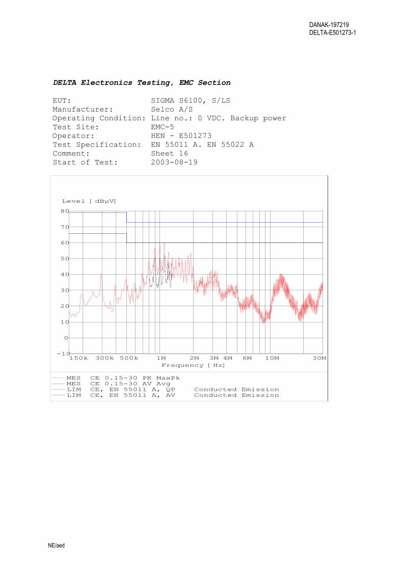
DELTA Electronics Testing, EMC Section EUT: SIGMA S6100, S/LS Manufacturer: Selco A/S Operating Condition: Line no.: 0 VDC. Backup power Test Site: EMC-5 Operator: HEN - E501273 Test Specification: EN 55011 A. EN 55022 A Comment: Sheet 16 Start of Test: 2003-08-19
-10
0
10
20
30
40
50
60
70
80
Level [dBµV]
150k 300k 500k 1M 2M 3M 4M 6M 10M 30MFrequency [Hz]
MES CE 0.15-30 PK MaxPk MES CE 0.15-30 AV Avg LIM CE, EN 55011 A, QP Conducted EmissionLIM CE, EN 55011 A, AV Conducted Emission

DANAK-197219 DELTA-E501273-1
NE/aed
DELTA Electronics Testing, EMC Section EUT: SIGMA S6000, IO/P Manufacturer: Selco A/S Operating Condition: Line no.: 0 VDC. Mains power Test Site: EMC-5 Operator: HEN - E501273 Test Specification: EN 55011 A. EN 55022 A Comment: Sheet 17 Start of Test: 2003-08-19
-10
0
10
20
30
40
50
60
70
80
Level [dBµV]
150k 300k 500k 1M 2M 3M 4M 6M 10M 30MFrequency [Hz]
MES CE 0.15-30 PK MaxPk MES CE 0.15-30 AV Avg LIM CE, EN 55011 A, QP Conducted EmissionLIM CE, EN 55011 A, AV Conducted Emission
DANAK-197219 DELTA-E501273-1
NE/aed
DELTA Electronics Testing, EMC Section EUT: SIGMA S6000, IO/P Manufacturer: Selco A/S Operating Condition: Line no.: +24 VDC. Mains power Test Site: EMC-5 Operator: HEN - E501273 Test Specification: EN 55011 A. EN 55022 A Comment: Sheet 18 Start of Test: 2003-08-19
-10
0
10
20
30
40
50
60
70
80
Level [dBµV]
150k 300k 500k 1M 2M 3M 4M 6M 10M 30MFrequency [Hz]
MES CE 0.15-30 PK MaxPk MES CE 0.15-30 AV Avg LIM CE, EN 55011 A, QP Conducted EmissionLIM CE, EN 55011 A, AV Conducted Emission
DANAK-197219 DELTA-E501273-1
NE/aed
DELTA Electronics Testing, EMC Section EUT: SIGMA S6000, IO/P Manufacturer: Selco A/S Operating Condition: Line no.: +24 VDC. Backup power Test Site: EMC-5 Operator: HEN - E501273 Test Specification: EN 55011 A. EN 55022 A Comment: Sheet 19 Start of Test: 2003-08-19
-10
0
10
20
30
40
50
60
70
80
Level [dBµV]
150k 300k 500k 1M 2M 3M 4M 6M 10M 30MFrequency [Hz]
MES CE 0.15-30 PK MaxPk MES CE 0.15-30 AV Avg LIM CE, EN 55011 A, QP Conducted EmissionLIM CE, EN 55011 A, AV Conducted Emission

DANAK-197219 DELTA-E501273-1
NE/aed
DELTA Electronics Testing, EMC Section EUT: SIGMA S6000, IO/P Manufacturer: Selco A/S Operating Condition: Line no.: 0 VDC. Backup power Test Site: EMC-5 Operator: HEN - E501273 Test Specification: EN 55011 A. EN 55022 A Comment: Sheet 20 Start of Test: 2003-08-19
-10
0
10
20
30
40
50
60
70
80
Level [dBµV]
150k 300k 500k 1M 2M 3M 4M 6M 10M 30MFrequency [Hz]
MES CE 0.15-30 PK MaxPk MES CE 0.15-30 AV Avg LIM CE, EN 55011 A, QP Conducted EmissionLIM CE, EN 55011 A, AV Conducted Emission
DANAK-197219 DELTA-E501273-1
NE/aed
DELTA Electronics Testing, EMC Section EUT: SIGMA S6500, UI Manufacturer: Selco A/S Operating Condition: Line no.: 0 VDC. Mains power Test Site: EMC-5 Operator: HEN - E501273 Test Specification: E10. IEC 60533. IEC 60945 Comment: Sheet 21 Start of Test: 2003-08-20
-20
0
20
40
60
80
100
Level [dBµV]
10k 20k 40k 100k 200k 400k 1M 2M 3M 5M 10M 30MFrequency [Hz]
MES CE 0.01-30 PK MaxPk LIM CE, E-10 gen. power Conducted EmissionLIM CE, IEC 60533, A General pwr distribution zoneLIM CE, IEC 60945, QP Conducted Emission
DANAK-197219 DELTA-E501273-1
NE/aed
DELTA Electronics Testing, EMC Section EUT: SIGMA S6500, UI Manufacturer: Selco A/S Operating Condition: Line no.: +24 VDC. Mains power Test Site: EMC-5 Operator: HEN - E501273 Test Specification: E10. IEC 60533. IEC 60945 Comment: Sheet 22 Start of Test: 2003-08-20
-20
0
20
40
60
80
100
Level [dBµV]
10k 20k 40k 100k 200k 400k 1M 2M 3M 5M 10M 30MFrequency [Hz]
MES CE 0.01-30 PK MaxPk LIM CE, E-10 gen. power Conducted EmissionLIM CE, IEC 60533, A General pwr distribution zoneLIM CE, IEC 60945, QP Conducted Emission

DANAK-197219 DELTA-E501273-1
NE/aed
DELTA Electronics Testing, EMC Section EUT: SIGMA S6500, UI Manufacturer: Selco A/S Operating Condition: Line no.: +24 VDC. Backup power Test Site: EMC-5 Operator: HEN - E501273 Test Specification: E10. IEC 60533. IEC 60945 Comment: Sheet 23 Start of Test: 2003-08-20
-20
0
20
40
60
80
100
Level [dBµV]
10k 20k 40k 100k 200k 400k 1M 2M 3M 5M 10M 30MFrequency [Hz]
MES CE 0.01-30 PK MaxPk LIM CE, E-10 gen. power Conducted EmissionLIM CE, IEC 60533, A General pwr distribution zoneLIM CE, IEC 60945, QP Conducted Emission

DANAK-197219 DELTA-E501273-1
NE/aed
DELTA Electronics Testing, EMC Section EUT: SIGMA S6500, UI Manufacturer: Selco A/S Operating Condition: Line no.: 0 VDC. Backup power Test Site: EMC-5 Operator: HEN - E501273 Test Specification: E10. IEC 60533. IEC 60945 Comment: Sheet 24 Start of Test: 2003-08-20
-20
0
20
40
60
80
100
Level [dBµV]
10k 20k 40k 100k 200k 400k 1M 2M 3M 5M 10M 30MFrequency [Hz]
MES CE 0.01-30 PK MaxPk LIM CE, E-10 gen. power Conducted EmissionLIM CE, IEC 60533, A General pwr distribution zoneLIM CE, IEC 60945, QP Conducted Emission

DANAK-197219 DELTA-E501273-1
NE/aed
DELTA Electronics Testing, EMC Section EUT: SIGMA S6000, IO/P Manufacturer: Selco A/S Operating Condition: Line no.: 0 VDC. Mains power Test Site: EMC-5 Operator: HEN - E501273 Test Specification: E10. IEC 60533. IEC 60945 Comment: Sheet 25 Start of Test: 2003-08-20
-20
0
20
40
60
80
100
Level [dBµV]
10k 20k 40k 100k 200k 400k 1M 2M 3M 5M 10M 30MFrequency [Hz]
MES CE 0.01-30 PK MaxPk LIM CE, E-10 gen. power Conducted EmissionLIM CE, IEC 60533, A General pwr distribution zone

DANAK-197219 DELTA-E501273-1
NE/aed
DELTA Electronics Testing, EMC Section EUT: SIGMA S6000, IO/P Manufacturer: Selco A/S Operating Condition: Line no.: +24 VDC. Mains power Test Site: EMC-5 Operator: HEN - E501273 Test Specification: E10. IEC 60533. Comment: Sheet 26 Start of Test: 2003-08-20
-20
0
20
40
60
80
100
Level [dBµV]
10k 20k 40k 100k 200k 400k 1M 2M 3M 5M 10M 30MFrequency [Hz]
MES CE 0.01-30 PK MaxPk LIM CE, E-10 gen. power Conducted EmissionLIM CE, IEC 60533, A General pwr distribution zone

DANAK-197219 DELTA-E501273-1
NE/aed
DELTA Electronics Testing, EMC Section EUT: SIGMA S6000, IO/P Manufacturer: Selco A/S Operating Condition: Line no.: +24 VDC. Backup power Test Site: EMC-5 Operator: HEN - E501273 Test Specification: E10. IEC 60533. Comment: Sheet 27 Start of Test: 2003-08-20
-20
0
20
40
60
80
100
Level [dBµV]
10k 20k 40k 100k 200k 400k 1M 2M 3M 5M 10M 30MFrequency [Hz]
MES CE 0.01-30 PK MaxPk LIM CE, E-10 gen. power Conducted EmissionLIM CE, IEC 60533, A General pwr distribution zone

DANAK-197219 DELTA-E501273-1
NE/aed
DELTA Electronics Testing, EMC Section EUT: SIGMA S6000, IO/P Manufacturer: Selco A/S Operating Condition: Line no.: 0 VDC. Backup power Test Site: EMC-5 Operator: HEN - E501273 Test Specification: E10. IEC 60533. Comment: Sheet 28 Start of Test: 2003-08-20
-20
0
20
40
60
80
100
Level [dBµV]
10k 20k 40k 100k 200k 400k 1M 2M 3M 5M 10M 30MFrequency [Hz]
MES CE 0.01-30 PK MaxPk LIM CE, E-10 gen. power Conducted EmissionLIM CE, IEC 60533, A General pwr distribution zone

DANAK-197219 DELTA-E501273-1
NE/aed
DELTA Electronics Testing, EMC Section EUT: SIGMA S6100, S/LS Manufacturer: Selco A/S Operating Condition: Line no.: 0 VDC. Mains power Test Site: EMC-5 Operator: HEN - E501273 Test Specification: E10. IEC 60533. Comment: Sheet 29 Start of Test: 2003-08-20
-20
0
20
40
60
80
100
Level [dBµV]
10k 20k 40k 100k 200k 400k 1M 2M 3M 5M 10M 30MFrequency [Hz]
MES CE 0.01-30 PK MaxPk LIM CE, E-10 gen. power Conducted EmissionLIM CE, IEC 60533, A General pwr distribution zone
DANAK-197219 DELTA-E501273-1
NE/aed
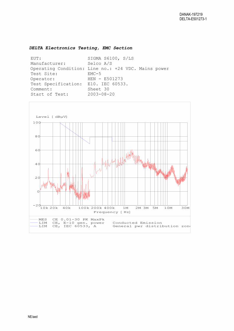
DELTA Electronics Testing, EMC Section EUT: SIGMA S6100, S/LS Manufacturer: Selco A/S Operating Condition: Line no.: +24 VDC. Mains power Test Site: EMC-5 Operator: HEN - E501273 Test Specification: E10. IEC 60533. Comment: Sheet 30 Start of Test: 2003-08-20
-20
0
20
40
60
80
100
Level [dBµV]
10k 20k 40k 100k 200k 400k 1M 2M 3M 5M 10M 30MFrequency [Hz]
MES CE 0.01-30 PK MaxPk LIM CE, E-10 gen. power Conducted EmissionLIM CE, IEC 60533, A General pwr distribution zone

DANAK-197219 DELTA-E501273-1
NE/aed
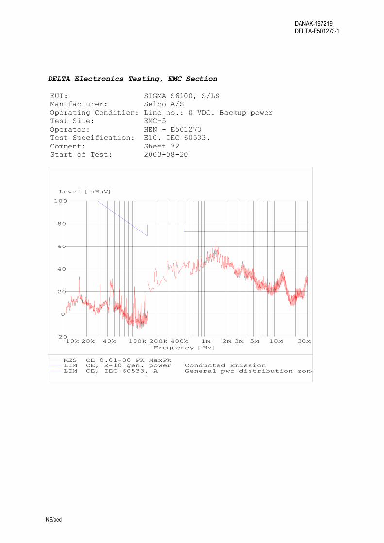
DELTA Electronics Testing, EMC Section EUT: SIGMA S6100, S/LS Manufacturer: Selco A/S Operating Condition: Line no.: +24 VDC. Backup power Test Site: EMC-5 Operator: HEN - E501273 Test Specification: E10. IEC 60533. Comment: Sheet 31 Start of Test: 2003-08-20
-20
0
20
40
60
80
100
Level [dBµV]
10k 20k 40k 100k 200k 400k 1M 2M 3M 5M 10M 30MFrequency [Hz]
MES CE 0.01-30 PK MaxPk LIM CE, E-10 gen. power Conducted EmissionLIM CE, IEC 60533, A General pwr distribution zone
DANAK-197219 DELTA-E501273-1
NE/aed
DELTA Electronics Testing, EMC Section EUT: SIGMA S6100, S/LS Manufacturer: Selco A/S Operating Condition: Line no.: 0 VDC. Backup power Test Site: EMC-5 Operator: HEN - E501273 Test Specification: E10. IEC 60533. Comment: Sheet 32 Start of Test: 2003-08-20
-20
0
20
40
60
80
100
Level [dBµV]
10k 20k 40k 100k 200k 400k 1M 2M 3M 5M 10M 30MFrequency [Hz]
MES CE 0.01-30 PK MaxPk LIM CE, E-10 gen. power Conducted EmissionLIM CE, IEC 60533, A General pwr distribution zone

DANAK-197219 DELTA-E501273-1
NE/aed
Annex 5
Test record sheets – Radiated emissions
(8 pages)

DANAK-197219 DELTA-E501273-1
NE/aed
DELTA Electronics Testing, EMC Section EUT: SIGMA S6000,IO/P. SIGMA S6100,S/LS. SIGMA S6500,UI Manufacturer: Selco A/S Operating Condition: Ant 0 deg Test Site: EMC-5 Operator: HEN - E501273 Test Specification: E10. IEC 60533. IEC 60945 Comment: Sheet 7 Start of Test: 2003-08-19
0
10
20
30
40
50
60
70
80
Level [dBµV/m]
150k 300k 500k 1M 2M 3M 4M 5M 7M 10M 30MFrequency [Hz]
MES ME IEC 945 (0 MaxPk LIM ME, E10, PWR QP Magnetic EmissionLIM ME, IEC60533, PWR QP Magnetic EmissionLIM ME, IEC 60945, QP Magnetic Emission
DANAK-197219 DELTA-E501273-1
NE/aed
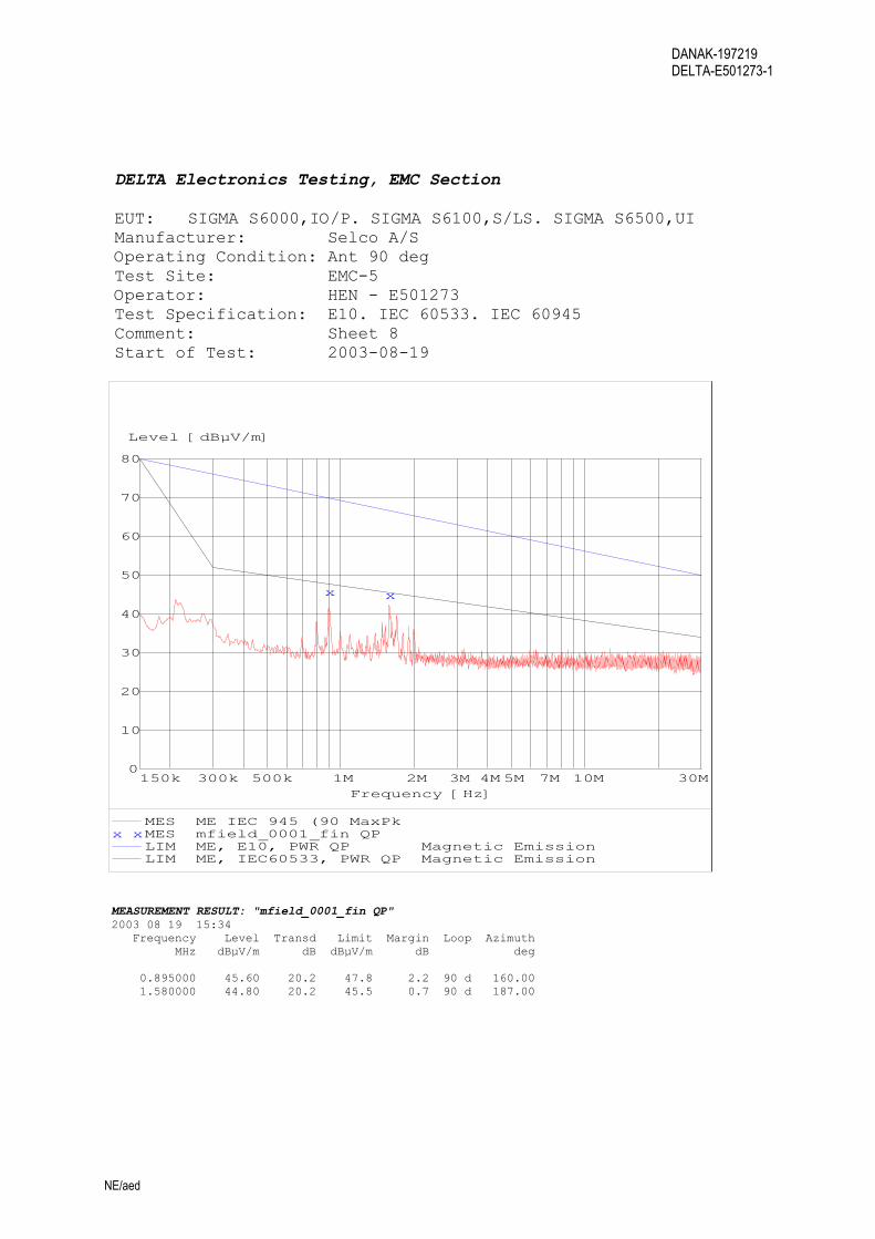
DELTA Electronics Testing, EMC Section EUT: SIGMA S6000,IO/P. SIGMA S6100,S/LS. SIGMA S6500,UI Manufacturer: Selco A/S Operating Condition: Ant 90 deg Test Site: EMC-5 Operator: HEN - E501273 Test Specification: E10. IEC 60533. IEC 60945 Comment: Sheet 8 Start of Test: 2003-08-19
0
10
20
30
40
50
60
70
80
Level [dBµV/m]
150k 300k 500k 1M 2M 3M 4M 5M 7M 10M 30MFrequency [Hz]
x x
MES ME IEC 945 (90 MaxPk x xMES mfield_0001_fin QP
LIM ME, E10, PWR QP Magnetic EmissionLIM ME, IEC60533, PWR QP Magnetic Emission
MEASUREMENT RESULT: "mfield_0001_fin QP" 2003 08 19 15:34 Frequency Level Transd Limit Margin Loop Azimuth MHz dBµV/m dB dBµV/m dB deg 0.895000 45.60 20.2 47.8 2.2 90 d 160.00 1.580000 44.80 20.2 45.5 0.7 90 d 187.00
DANAK-197219 DELTA-E501273-1
NE/aed
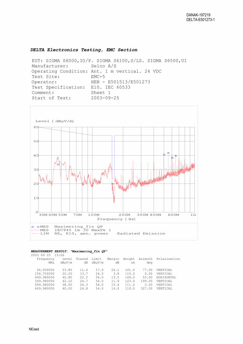
DELTA Electronics Testing, EMC Section EUT: SIGMA S6000,IO/P. SIGMA S6100,S/LS. SIGMA S6500,UI Manufacturer: Selco A/S Operating Condition: Ant. 1 m vertical. 24 VDC Test Site: EMC-5 Operator: HEN - E501513/E501273 Test Specification: E10. IEC 60533 Comment: Sheet 1 Start of Test: 2003-09-25
0
10
20
30
40
50
60
Level [dBµV/m]
30M 40M 50M 70M 100M 200M 300M 400M 600M 1GFrequency [Hz]
x
x
xx
xx
x xMES Maximering_fin QP MES IEC945 1m 30 MaxPk 1 LIM RE, E10, gen. power Radiated Emission
MEASUREMENT RESULT: "Maximering_fin QP" 2003 09 25 15:06 Frequency Level Transd Limit Margin Height Azimuth Polarisation MHz dBµV/m dB dBµV/m dB cm deg 46.000000 33.80 11.4 57.9 24.1 101.0 77.00 VERTICAL 156.700000 20.20 13.7 24.0 3.8 110.0 0.00 VERTICAL 499.980000 40.80 22.2 54.0 13.2 169.0 53.00 HORIZONTAL 549.980000 42.10 24.7 54.0 11.9 123.0 199.00 VERTICAL 599.980000 38.60 24.3 54.0 15.4 111.0 2.00 VERTICAL 649.980000 40.00 24.8 54.0 14.0 110.0 327.00 VERTICAL

DANAK-197219 DELTA-E501273-1
NE/aed
DELTA Electronics Testing, EMC Section EUT: SIGMA S6000,IO/P. SIGMA S6100,S/LS. SIGMA S6500,UI Manufacturer: Selco A/S Operating Condition: Ant. 3 m horizontal. 24 VDC Test Site: EMC-5 Operator: HEN - E501513/E501273 Test Specification: E10. IEC 60533 Comment: Sheet 2 Start of Test: 2003-09-25
0
10
20
30
40
50
60
Level [dBµV/m]
30M 40M 50M 70M 100M 200M 300M 400M 600M 1GFrequency [Hz]
x
x
xx
xx
MES IEC945 4m 30 MaxPk 1 MES IEC945 4m 30 MaxPk 2 MES IEC945 4m 30 MaxPk 3
x xMES Maximering_fin QP

DANAK-197219 DELTA-E501273-1
NE/aed
DELTA Electronics Testing, EMC Section EUT: SIGMA S6000,IO/P. SIGMA S6100,S/LS. SIGMA S6500,UI Manufacturer: Selco A/S Operating Condition: Ant 1 m vertical Test Site: EMC-5 Operator: HEN - E501273 Test Specification: E10. IEC 60533 Comment: Sheet 5 Start of Test: 2003-08-19
0
10
20
30
40
50
60
Level [dBµV/m]
1G 1.2G 1.4G 1.6G 1.8G 2GFrequency [Hz]
MES RE 1mv 1-2GHz MaxPk x xMES Maximering_fin QP
LIM RE, IEC 60533 (1-2G) Radiated Emission

DANAK-197219 DELTA-E501273-1
NE/aed
DELTA Electronics Testing, EMC Section EUT: SIGMA S6000,IO/P. SIGMA S6100,S/LS. SIGMA S6500,UI Manufacturer: Selco A/S Operating Condition: Ant 3 m horizontal Test Site: EMC-5 Operator: HEN - E501273 Test Specification: E10. IEC 60533 Comment: Sheet 6 Start of Test: 2003-08-19
0
10
20
30
40
50
60
Level [dBµV/m]
1G 1.2G 1.4G 1.6G 1.8G 2GFrequency [Hz]
MES RE 4mh 1-2GHz MaxPk x xMES Maximering_fin QP
LIM RE, IEC 60945 Radiated Emission

DANAK-197219 DELTA-E501273-1
NE/aed
DELTA Electronics Testing, EMC Section EUT: SIGMA S6000,IO/P. SIGMA S6100,S/LS. SIGMA S6500,UI Manufacturer: Selco A/S Operating Condition: Ant 1 m vertical Test Site: EMC-5 Operator: HEN - E501273 Test Specification: EN 55011 A. EN 55022 A Comment: Sheet 1 Start of Test: 2003-08-19
0
10
20
30
40
50
Level [dBµV/m]
30M 40M 50M 70M 100M 200M 300M 400M 600M 1GFrequency [Hz]
x
x
xx
x
x xx
x xMES Maximering_fin QP MES RE 1mv 30-1000 MaxPk LIM RE, EN 55011 A, QP Radiated Emission
MEASUREMENT RESULT: "Maximering_fin QP" 2003 08 19 11:37 Frequency Level Transd Limit Margin Height Azimuth Polarisation MHz dBµV/m dB dBµV/m dB cm deg 46.700000 37.10 10.8 40.0 2.9 101.0 274.00 VERTICAL 76.900000 21.30 8.3 40.0 18.7 391.0 0.00 HORIZONTAL 149.990000 27.90 12.7 40.0 12.1 101.0 0.00 VERTICAL 160.000000 27.30 11.7 40.0 12.7 101.0 358.00 VERTICAL 199.990000 36.20 11.4 40.0 3.8 376.0 114.00 HORIZONTAL 399.990000 44.00 18.2 47.0 3.0 283.0 165.00 HORIZONTAL 449.980000 44.50 19.4 47.0 2.5 177.0 291.00 HORIZONTAL 499.980000 46.20 20.4 47.0 0.8 190.0 178.00 HORIZONTAL

DANAK-197219 DELTA-E501273-1
NE/aed
DELTA Electronics Testing, EMC Section EUT: SIGMA S6000,IO/P. SIGMA S6100,S/LS. SIGMA S6500,UI Manufacturer: Selco A/S Operating Condition: Ant 4 m horizontal Test Site: EMC-5 Operator: HEN - E501273 Test Specification: EN 55011 A. EN 55022 A Comment: Sheet 2 Start of Test: 2003-08-19
0
10
20
30
40
50
Level [dBµV/m]
30M 40M 50M 70M 100M 200M 300M 400M 600M 1GFrequency [Hz]
x
x
xx
x
x xx
MES RE 4mh 30-1000 MaxPk x xMES Maximering_fin QP
LIM RE, EN 55011 A, QP Radiated EmissionLIM RE, EN 55022 A, QP Radiated Emission
DANAK-197219 DELTA-E501273-1
NE/aed
Annex 6
Explanatory notes regarding modifications (from Selco A/S)
(2 pages)
DANAK-197219 DELTA-E501273-1
NE/aed
Modifications
The following modifications were made before the SIGMA modules passed the conducted radio frequency interference testing, the surge testing, the electrostatic discharge testing and the radiated emission measurements.
S6000:
• Varistor between Primary supply kl.1 (+24V) and earth
• Varistor between Primary supply kl.2 (GND) and earth
• Varistor between Primary supply kl.1 (+24V) and Primary supply kl.2 (GND)
• Varistor between Backup supply kl.1 (+24V) and earth
• Varistor between Backup supply kl.2 (GND) and earth
• Varistor between Backup supply kl.1 (+24V) and Backup supply kl.2 (GND)
• 1nF kapacitor placed between GND_MH and earth on MCU board
• 100nF kapacitor placed between analog outputs kl.1 and earth
• 100nF kapacitor placed between analog outputs kl.2 and earth
• 100nF kapacitor placed between analog outputs kl.4 and earth
• 100nF kapacitor placed between analog outputs kl.5 and earth
• 100nF kapacitor placed between analog outputs kl.7 and earth
• 100nF kapacitor placed between analog outputs kl.8 and earth
S6100:
• Varistor between Primary supply kl.1 (+24V) and earth
• Varistor between Primary supply kl.2 (GND) and earth
• Varistor between Primary supply kl.1 (+24V) and Primary supply kl.2 (GND)
• Varistor between Backup supply kl.1 (+24V) and earth
• Varistor between Backup supply kl.2 (GND) and earth
• Varistor between Backup supply kl.1 (+24V) and Backup supply kl.2 (GND)
DANAK-197219 DELTA-E501273-1
NE/aed
• 1nF kapacitor placed between GND_MH and earth on MCU board
• 100nF kapacitor placed between analog outputs kl.1 and earth
• 100nF kapacitor placed between analog outputs kl.2 and earth
• 100nF kapacitor placed between analog outputs kl.5 and earth
• 100nF kapacitor placed between analog outputs kl.6 and earth
S6500:
• Varistor between Primary supply kl.1 (+24V) and earth
• Varistor between Primary supply kl.2 (GND) and earth
• Varistor between Primary supply kl.1 (+24V) and Primary supply kl.2 (GND)
• Varistor between Backup supply kl.1 (+24V) and earth
• Varistor between Backup supply kl.2 (GND) and earth
• Varistor between Backup supply kl.1 (+24V) and Backup supply kl.2 (GND)
• SW2 removed