Type 75 - werkus.pl · 90pp-050-75-5 5040 46222,0 5 Ms-10x25-912 ... aluminium up to a Si-component...
12
The Milling System Jongen Werkzeugtechnik Type 75
Transcript of Type 75 - werkus.pl · 90pp-050-75-5 5040 46222,0 5 Ms-10x25-912 ... aluminium up to a Si-component...

The Milling System
Jongen Werkzeugtechnik
Type75
2
The Tool
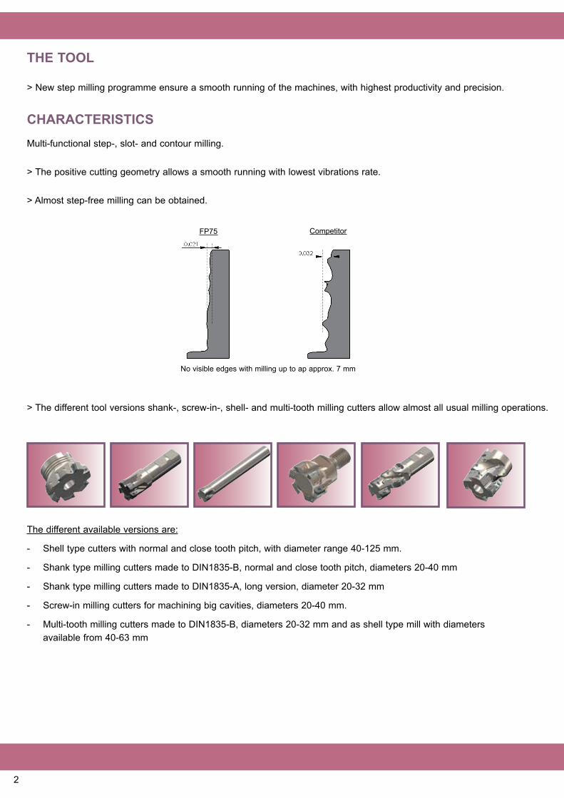
> New step milling programme ensure a smooth running of the machines, with highest productivity and precision.
CharaCTerisTiCsMulti-functional step-, slot- and contour milling.
> The positive cutting geometry allows a smooth running with lowest vibrations rate.
> Almost step-free milling can be obtained.
The different available versions are:
- Shell type cutters with normal and close tooth pitch, with diameter range 40-125 mm.
- Shank type milling cutters made to DIN1835-B, normal and close tooth pitch, diameters 20-40 mm
- Shank type milling cutters made to DIN1835-A, long version, diameter 20-32 mm
- Screw-in milling cutters for machining big cavities, diameters 20-40 mm.
- Multi-tooth milling cutters made to DIN1835-B, diameters 20-32 mm and as shell type mill with diameters available from 40-63 mm
No visible edges with milling up to ap approx. 7 mm
FP75 Competitor
> The different tool versions shank-, screw-in-, shell- and multi-tooth milling cutters allow almost all usual milling operations.

3
> Different numbers of teeth ensure the application in terms of roughing, finishing, big cavities etc.
Internal coolant passage
> All tools include internal coolant passages
Contouring
Pocket MillingPlungingRamping Face Milling
Shoulder Milling
3-D CopyProfile Milling
Full slot Milling
appliCaTion areas

4
FP75 FP76
The inserT
Precision sintered version
Completely ground Version
> 2-edge step milling insert with a depth of cut (ap) of up to 10 mm, positive geometry.
> The starting sales programme includes precision sintered as well as completely ground inserts, with different edge radii.
> Almost all usual materials can be processed, that means from the aluminium machining, difficult materials, over the cast iron machining and the machining of different steels.
Following carbide qualities are offered:
hT30Code 29, Iso-Classifizierung M20-M35
Hard wearing and tough fi nest grain carbide with an AlTiN- Nanocomposit-coating for middle cutting speeds and middle feed rates. This quality is suitable for dry milling and can also be adopted with cooling. Application areas are roughing and fi nishing high grade steel as well as high alloyed materials.
hT50Code 22, Iso-Classifizierung P30-P35
Very tough fi ne grain carbide quality with a TiAlN-coating for middle to high cutting speeds and high feed rates. This quality is suitable for dry milling and can also be adopted with cooling. Application areas are roughing and fi nishing of almost all steels and cast iron materials, e.g. structural steel, tool steel, heattreatable steel as well as unalloyed steel, low alloyed steel, high alloyed steel and also grey cast iron, globular graphite cast iron etc.
hT32Code 33, Iso-Classifizierung M20-M30
Hard wearing and tough fi nest grain carbide with an AlTiN- Nanocomposit-coating for medium to high cutting speedsand middle feed rates. This quality is equally applicable for dry as well as wet milling. It is especially suited for processing stainless steel, tool steel as well as high alloyed steel.
hT20Code 32, Iso-Classifizierung K15-K20
Very hard wearing fi ne grain carbide with an AlTiN- Nanocomposit-coating for middle – high cutting speeds with high feed rates. This quality is suitable for dry milling and can also be adopted with cooling. Application areas are roughing and fi nishing of cast iron materials, e.g. grey-, tempered-, vermicular-, graphite- and globular graphite cast iron.
hT45Code 31, Iso-Classifizierung P30-P35
Very tough fi ne grain carbide with an AlTiN- Nanocomposit-coating for middle to high cutting speeds with high feed rates. This quality is suitable for dry milling and can also be adopted with cooling. Application areas are roughing and fi nishing of almost all steels and cast iron qualities such as: structural steel, tool steel, heat-treatable steel as well as unalloyed steel, low alloyed steel, high alloyed steel and also grey cast iron, globular graphite cast iron etc.

5
order-nr. D h d B s Z Ms 90pp-040-75-16-4 40 40 16 32 2,0 4 Ms-8x25-912 90pp-040-75-22-4 40 40 22 38 2,0 4 Ms-10x25-912 90pp-050-75-5 50 40 22 46 2,0 5 Ms-10x25-912 90pp-063-75-5 63 40 22 46 2,0 5 Ms-10x25-912 90pp-080-75-7 80 50 27 54 2,0 7 Ms-12x35-912 90pp-100-75-9 100 50 32 64 2,0 9 Ms-16x30-912 90pp-125-75-13 125 50 40 90 2,0 13 Ms-20x45-7991
Close teeth pitch 90pp-040-75-16-5 40 40 16 32 2,0 5 Ms-8x25-912 90pp-040-75-22-5 40 40 22 38 2,0 5 Ms-10x25-912 90pp-050-75-6 50 40 22 46 2,0 6 Ms-10x25-912 90pp-063-75-7 63 40 22 46 2,0 7 Ms-10x25-912 90pp-080-75-9 80 50 27 54 2,0 9 Ms-12x35-912 90pp-100-75-12 100 50 32 64 2,0 12 Ms-16x30-912
shell Type Milling Cutters
TeChniCal DaTa
KT28Code 23, Iso-Classifizierung K15-K20
Very hard wearing fi ne grain carbide with a TiAlN-coating for middle to high cutting speeds and high feed rates. This quality is suitable for dry milling and can also be adopted with cooling. Application areas are roughing and fi nishing of cast iron materials such as: grey-, tempered-, vermicular-, graphite- and globular graphite cast iron.
K15MCode 8, Iso-Classifizierung K10
Very hard wearing fi ne grain carbide, for high cutting speeds with high feed rates. This quality is suitable for dry milling and can also be adopted with cooling. Application areas are roughing and fi nishing nonferrous heavy materials and aluminium up to a Si-component of approx. 8%.

6
order-nr. D l d n s Z 90pp-20-32-75-2 20 82,4 20 32 2,0 2 90pp-20-50-75-2 20 100,4 20 50 2,0 2 90pp-22-33-75-3 22 83,3 20 33 2,0 3 90pp-25-38-75-3 25 95,2 25 38 2,0 3 90pp-25-60-75-3 25 117,2 25 60 2,0 3 90pp-28-42-75-4 28 98,4 25 42 2,0 4 90pp-30-45-75-4 30 101,3 25 45 2,0 4 90pp-32-48-75-3 32 104,3 25 48 2,0 3 90pp-32-60-75-3 32 116,3 25 60 2,0 3 90pp-36-48-75-5 36 104,2 25 48 2,0 5 90pp-40-48-75-5 40 104,1 25 48 2,0 5
Close teeth pitch 90pp-20-30-75-3 20 81,8 20 30 2,0 3 90pp-25-38-75-4 25 95,2 25 38 2,0 4 90pp-32-48-75-5 32 104,3 25 48 2,0 5
shank Type Milling Cutters made to Din 1835-B (Weldon)
order-nr. D l d n s Z 90pp-20-75-2-150 20 150 18 30 2,0 2 90pp-25-75-2-170 25 170 20 32 2,0 2 90pp-32-75-3-195 32 195 25 30 2,0 3
shank Type Milling Cutters made to Din 1836 (cylindrical)

7
screw-in Cutters
order-nr. D l M B sW s Z esF-20-27-M10-75-2 20 27 M10 18,0 SW16 2,0 2 esF-25-32-M12-75-3 25 32 M12 21,0 SW18 2,0 3 esF-32-32-M16-75-3 32 32 M16 29,0 SW24 2,0 3 esF-35-32-M16-75-4 35 32 M16 29,0 SW24 2,0 4 esF-40-32-M16-75-4 40 32 M16 29,0 SW24 2,0 4

8
Multi-Tooth Milling Cutters
order-nr. D sl h d B s Zeff. ZZ MsVZF 40-35-75-3 KD16 40 35 54 16 36 2,0 3 12 Ms-8x50-912VZF 50-35-75-4 KD22 50 35 60 22 46 2,0 4 16 Ms-10x50-912VZF 63-44-75-5 KD27 63 44 69 27 55 2,0 5 25 Ms-12x60-912
order-nr. D sl n l d s Zeff. ZZVZF 20-18-20-75-2 20 20 50 100 20 2,0 2 4VZF 25-27-25-75-2 25 27 54 110 25 2,0 2 6VZF 28-27-25-75-2 28 27 54 110 25 2,0 2 6VZF 32-44-25-75-3 32 44 54 110 25 2,0 3 12VZF 32-44-32-75-3 32 44 60 120 32 2,0 3 12

hT45hT50hT32hT30KT28
hT45hT32hT20
Fp 75(B17)
Fp 275(B17)
12,0x7,0 R1,0
12,0x7,0 R0,8
T08+
ss2,5-7
100g
9
Fp 75 r0,4(B17)
Fp 275 r0,4(B17)
12,0x7,0 R0,4
12,0x7,0 R0,4
Fp 76 r0,2(B17)
12,0x7,0 R0,2
Fp 76 r0,4(B17)
12,0x7,0 R0,4
Fp 76 r0,6(B17)
12,0x7,0 R0,6
Fp 76 r0,8(B17)
12,0x7,0 R0,8
hT45hT50hT32hT30KT28
hT45hT32hT20
K15M
hT50hT30KT28
hT50hT30KT28
hT50hT30KT28
Fp 76 r0,4(B17)
12,0x7,0 R0,4
K15M
Fp 76 r0,6(B17)
12,0x7,0 R0,6
K15M
ss2,5-6
precision sintered with chip breaker
F Application areas and parameters see page 10
screw driver
heavy duty grease
Fixing screw
inserts
spare parts
precision sintered with chip breaker
F Application areas and parameters see page 10
precision ground with polished chip breaker
F Application areas and parameters see page 10
precision ground with chip breaker
F Application areas and parameters see page 10
precision ground with chip breaker
F Application areas and parameters see page 10
precision ground with chip breaker
F Application areas and parameters see page 10
Fp75
Fp76
precision ground with polished chip breaker
F Application areas and parameters see page 10
precision ground with polished chip breaker
F Application areas and parameters see page 10
tightening torque
1,2 - 1,3 nm
Fixing screw for tools with diam. 20tightening torque
1,2 - 1,3 nm
precision sintered with chip breaker
F Application areas and parameters see page 10
precision sintered with chip breaker
F Application areas and parameters see page 10

10
Material Hardness Quality Depth of cut ae [mm]
Cutting speed Vc [m/min.]
P
Structural steel,Unalloyed steel <180 HB HT45
HT50
-0,25D
250(200-350)
-0,5D
-0,75D
>0,75D-1D
Tool steel,Heat-treatable steel,
Alloyed steel180-350 HB
HT45HT50
(HT32)
-0,25D
220(160-280)
-0,5D
-0,75D
>0,75D-1D
MStainless-steel,
High grade steel,High alloyed steel,
<270 HBHT30 HT32
(HT45) (HT50)
-0,25D
240(140-300)
-0,5D
-0,75D
>0,75D-1D
S Heat-resistant super alloysTitan alloys
HT30HT32
-0,25D
60 (40-200)
-0,5D
-0,75D
>0,75D-1D
H Tempered steel 40-55 HRC HT20KT28
-0,25D
80(50-120)
-0,5D
-0,75D
>0,75D-1D
K
Grey cast iron <800 N/mm² HT20KT28
-0,25D
250(180-350)
-0,5D
-0,75D
>0,75D-1D
Globular graphite cast iron <350 N/mm²HT20KT28
(HT45) (HT50)
-0,25D
200(130-280)
-0,5D
-0,75D
>0,75D-1D
N AluminiumNon-ferrous metals bis 12% Si K15M
-0,25D
500(500-1000)
-0,5D
-0,75D
>0,75D-1D
The above mentioned data are standard values.Up and down corrections are admitted depending on the machine type, tool and holding fixture.
paraMeTers sTep MillinG
11
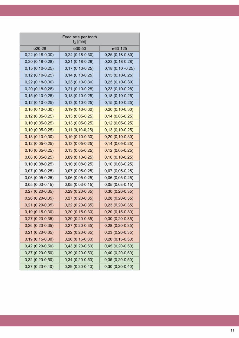
Feed rate per toothfz [mm]
ø20-28 ø30-50 ø63-1250,22 (0,18-0,30) 0,24 (0,18-0,30) 0,25 (0,18-0,30)
0,20 (0,18-0,28) 0,21 (0,18-0,28) 0,23 (0,18-0,28)
0,15 (0,10-0,25) 0,17 (0,10-0,25) 0,18 (0,10 -0,25)
0,12 (0,10-0,25) 0,14 (0,10-0,25) 0,15 (0,10-0,25)
0,22 (0,18-0,30) 0,23 (0,10-0,30) 0,25 (0,10-0,30)
0,20 (0,18-0,28) 0,21 (0,10-0,28) 0,23 (0,10-0,28)
0,15 (0,10-0,25) 0,18 (0,10-0,25) 0,18 (0,10-0,25)
0,12 (0,10-0,25) 0,13 (0,10-0,25) 0,15 (0,10-0,25)
0,18 (0,10-0,30) 0,19 (0,10-0,30) 0,20 (0,10-0,30)
0,12 (0,05-0,25) 0,13 (0,05-0,25) 0,14 (0,05-0,25)
0,10 (0,05-0,25) 0,13 (0,05-0,25) 0,12 (0,05-0,25)
0,10 (0,05-0,25) 0,11 (0,10-0,25) 0,13 (0,10-0,25)
0,18 (0,10-0,30) 0,19 (0,10-0,30) 0,20 (0,10-0,30)
0,12 (0,05-0,25) 0,13 (0,05-0,25) 0,14 (0,05-0,25)
0,10 (0,05-0,25) 0,13 (0,05-0,25) 0,12 (0,05-0,25)
0,08 (0,05-0,25) 0,09 (0,10-0,25) 0,10 (0,10-0,25)
0,10 (0,08-0,25) 0,10 (0,08-0,25) 0,10 (0,08-0,25)
0,07 (0,05-0,25) 0,07 (0,05-0,25) 0,07 (0,05-0,25)
0,06 (0,05-0,25) 0,06 (0,05-0,25) 0,06 (0,05-0,25)
0,05 (0,03-0,15) 0,05 (0,03-0,15) 0,05 (0,03-0,15)
0,27 (0,20-0,35) 0,29 (0,20-0,35) 0,30 (0,20-0,35)
0,26 (0,20-0,35) 0,27 (0,20-0,35) 0,28 (0,20-0,35)
0,21 (0,20-0,35) 0,22 (0,20-0,35) 0,23 (0,20-0,35)
0,19 (0,15-0,30) 0,20 (0,15-0,30) 0,20 (0,15-0,30)
0,27 (0,20-0,35) 0,29 (0,20-0,35) 0,30 (0,20-0,35)
0,26 (0,20-0,35) 0,27 (0,20-0,35) 0,28 (0,20-0,35)
0,21 (0,20-0,35) 0,22 (0,20-0,35) 0,23 (0,20-0,35)
0,19 (0,15-0,30) 0,20 (0,15-0,30) 0,20 (0,15-0,30)
0,42 (0,20-0,50) 0,43 (0,20-0,50) 0,45 (0,20-0,50)
0,37 (0,20-0,50) 0,39 (0,20-0,50) 0,40 (0,20-0,50)
0,32 (0,20-0,50) 0,34 (0,20-0,50) 0,35 (0,20-0,50)
0,27 (0,20-0,40) 0,29 (0,20-0,40) 0,30 (0,20-0,40)

12
D1 Ramping Angle Circular boring(flat surface)
Circular milling (wavy surface)
Anlge of leadmax. α (°)
Processing distancemin. L (mm)
Diam.max. DH(mm)
Depth of cut max. cycle P (mm)
Diam.min. DH(mm)
Depth of cut max. cycle P (mm)
Diam.min. DH(mm)
Depth of cut max. cycle P (mm)
20 8,7 52 39,2 4,6 38 4,3 33,5 3,322 7,6 60 43,2 4,4 42 4,2 37,5 3,225 6,3 72 49,2 4,2 48 4,0 43,5 3,228 5,4 84 55,2 4,1 54 3,9 49,5 3,230 5,0 92 59,2 4,0 58 3,8 53,5 3,232 4,6 100 63,2 3,9 62 3,8 57,5 3,236 3,9 116 71,2 3,8 70 3,7 65,5 3,240 3,5 132 79,2 3,7 78 3,6 73,5 3,250 2,7 172 99,2 3,6 98 3,5 93,5 3,263 2,0 224 125,2 3,5 124 3,4 119,5 3,280 1,6 292 159,2 3,4 158 3,4 153,5 3,2
100 1,2 372 199,2 3,4 198 3,3 193,5 3,2125 1,0 472 249,2 3,3 248 3,3 243,5 3,2
Formula for calculating the max. angle of immersion:
tan α = s
(D-7)
s = Variable (see above)7 = Insert’s widthD = Tool diam.
07/1
2 Jongen Werkzeugtechnik Gmbh & Co. KGSiemensring 11 · D-47877 Willich · Germany
Phone: 0049 2154 / 95 330 350 · Fax: 0049 2154 / 95 330 500www.jongen.de · email: [email protected]
Ramping Circular milling wavy surface
Circular boringeven surface
paraMeTers proFile MillinG anD CirCUlar MillinG
Ramping Circular milling wavy surface
Circular boringeven surface
Errors and omissions excepted.