
TYPE 45FS1/45UVFS1 FLAME SIGNATURE SCANNER™ · PDF fileall fuel types (gas/oil/coal)....
32
1 TYPE 45FS1/45UVFS1 MODEL 1000, 1001 FLAME SIGNATURE SCANNER™ DESCRIPTION The FIREYE ® Type 45FS1 and 45UVFS1 Signature Scanner™ flame detectors incorporate an inno- vative flame detection method to determine the presence or absence of a target flame in a single or multiple burner environment. Both scanners utilize a software algorithm that constantly compares the amplitude-frequency characteristics of the target flame with the amplitude-frequency characteris- tics that they learn during a setup procedure. This amplitude-frequency characteristic will be referred to as the signature of the target flame. During the learn mode the scanner performs “real time” anal- ysis of the frequency spectrum of the AC signal of the target flame to determine the type of flame being sensed (e.g. burner flame-on, flame tips from adjacent burners, background flame, no flames, etc.) and determines a specific shape or Flame Signature of the flame’s frequency spectrum. When the scanner is put in the run mode, the Signature Scanner controls constantly compare the targeted flame signal with the learned signatures to determine the status of the flame. The 45FS1/45UVFS1 then provides a pulsed output to indicate that the flame signal matches its learned flame signature. This pulse output is analogous to the strength of the flame signal, allowing the scanner to be compatible with the 25SU3 and 25SU5 style flame amplifiers. The main difference between the 45FS1 and 45UVFS1 scanners is the flame detector utilized in each scanner. The 45FS1 scanner incorporates a large area lead sulfide cell sensitive to the infra-red range more suitable for coal and/or oil type flames. This cell can detect a wide range of background bright- ness without experiencing cell washout. The 45UVFS1 scanner uses a super-blue silicon cell sensi- tive to the UV range, as well as an automatic signal amplification circuitry making it applicable for all fuel types (gas/oil/coal). The Signature Scanner flame detectors have the ability for remote communication to review and program the system setpoints as well as download and upload the “learned” flame signature data from one scanner to another using an IBM compatible PC and the FS700 software program. Refer to Bulletin CU-39 for details. The 45FS1/45UVFS1 Scanners have an eight (8) character LED display, a three (3) pushbutton key- pad, and a program enable pushbutton to program and/or review the various system setpoints and operating parameters associated with the setup procedure and operation of the scanner. Flame signa- tures can be learned for a number of fuel types (gas, oil, coal, etc.). The selection of the flame signa- ture is determined via the keypad or the remote file selector switches. CU-32 APRIL 5, 2013
Transcript of TYPE 45FS1/45UVFS1 FLAME SIGNATURE SCANNER™ · PDF fileall fuel types (gas/oil/coal)....

1
TYPE 45FS1/45UVFS1MODEL 1000, 1001
FLAMESIGNATURESCANNER™
DESCRIPTIONThe FIREYE® Type 45FS1 and 45UVFS1 Signature Scanner™ flame detectors incorporate an inno-vative flame detection method to determine the presence or absence of a target flame in a single ormultiple burner environment. Both scanners utilize a software algorithm that constantly comparesthe amplitude-frequency characteristics of the target flame with the amplitude-frequency characteris-tics that they learn during a setup procedure. This amplitude-frequency characteristic will be referredto as the signature of the target flame. During the learn mode the scanner performs “real time” anal-ysis of the frequency spectrum of the AC signal of the target flame to determine the type of flamebeing sensed (e.g. burner flame-on, flame tips from adjacent burners, background flame, no flames,etc.) and determines a specific shape or Flame Signature of the flame’s frequency spectrum. Whenthe scanner is put in the run mode, the Signature Scanner controls constantly compare the targetedflame signal with the learned signatures to determine the status of the flame.
The 45FS1/45UVFS1 then provides a pulsed output to indicate that the flame signal matches itslearned flame signature. This pulse output is analogous to the strength of the flame signal, allowingthe scanner to be compatible with the 25SU3 and 25SU5 style flame amplifiers.
The main difference between the 45FS1 and 45UVFS1 scanners is the flame detector utilized in eachscanner. The 45FS1 scanner incorporates a large area lead sulfide cell sensitive to the infra-red rangemore suitable for coal and/or oil type flames. This cell can detect a wide range of background bright-ness without experiencing cell washout. The 45UVFS1 scanner uses a super-blue silicon cell sensi-tive to the UV range, as well as an automatic signal amplification circuitry making it applicable forall fuel types (gas/oil/coal).
The Signature Scanner flame detectors have the ability for remote communication to review andprogram the system setpoints as well as download and upload the “learned” flame signature datafrom one scanner to another using an IBM compatible PC and the FS700 software program. Refer toBulletin CU-39 for details.
The 45FS1/45UVFS1 Scanners have an eight (8) character LED display, a three (3) pushbutton key-pad, and a program enable pushbutton to program and/or review the various system setpoints andoperating parameters associated with the setup procedure and operation of the scanner. Flame signa-tures can be learned for a number of fuel types (gas, oil, coal, etc.). The selection of the flame signa-ture is determined via the keypad or the remote file selector switches.
CU-32APRIL 5, 2013

2
PROGRAMMING THE 45FS1/45UVFS1 FLAME SIGNATURE SCANNERInformation on the setup procedure and programming for the 45FS1/45UVFS1 flame SignatureScanner can be found later in this bulletin, as well as the programming primer (CU-33).
OPERATIONThe 45FS1/45UVFS1 flame scanner utilizes a microcomputer which continually monitors the fre-quency spectrum of the sensed flame and compares it against the flame signature that is stored in itsmemory. The degree of uniformity of the measured flame to its signature determines the flames sta-bility.
A Setup procedure in which the 45FS1/45UVFS1 scanner “Learns” the various conditions (e.g.burner on, burner off, etc.) is required for the proper operation of the scanner. See Programming theFlame Signature Scanner and the Programming Primer (CU-33).
The 45FS1/45UVFS1 flame scanners are compatible with the following Flame Safeguard controls:
— Fireye Type 25SU3, Model -2000, -2100, 4170, 4172, 5166, 5168, 5172, 5173
— Fireye Type 25SU5, Model 5011, 5012
(Refer to Figures 19, 20, and 21 for wiring diagrams).
APPLICATIONThe type of burner and fuel will affect the frequency and amplitude characteristics of the flame. Gas-eous flames (propane, methane, natural gas) tend to have a low flame amplitude, while solid pulver-ized (coal) and liquid (oil) flames have a high flame amplitude. The type of burner will affect thefrequency of the flame (gun type = high flame frequency, low nox = low flame frequency).
A further explanation of the nature of flames will also assist in scanner selection. Oil and coalflames produce soot and flash respectively during the combustion process which makes these flamesopaque in the infra-red range. An infra-red detector will recognize the infra-red radiation in the targetflame but will not see through the flame to detect the infra-red radiation associated with the opposedflame. In the event of a flame out condition, the flame signature of the background radiation (e.g.opposed flame tips) should be unique enough to provide proper discrimination (See “Learn FlameOn/Off - Setpoints Menu” and “Discrimination - Status Menu”).
A gas flame is a very clean burning fuel that is mostly transparent to an infra-red detector. Thismeans an infra-red detector will detect the infra-red radiation in the target flame but will also seedirectly through the flame and pick up any infra-red radiation associated with an opposed flame.Consequently, when an infra-red detector is used on a gas flame, care should be taken so the line ofsight of the scanner does not pick up any other source of infra-red radiation (e.g. single burner orfront fired applications are acceptable, opposed fired may cause discrimination problems).
A gas flame also emits a large amount of ultra-violet radiation. However, during the combustion pro-cess, water vapor is also produced at the leading edge of the gas flame. This water vapor will absorbmost of the UV radiation. The water vapor now makes a gas flame opaque to an ultra-violet detector,allowing the UV detector to pick up the UV radiation within the target flame, but not see through theflame (due to the water vapor) to pick up UV radiation from opposed flames in an opposed firedburner. In the event of a flame out condition, the flame signature of the background radiation (e.g.opposed flame tips) should be unique enough to provide proper discrimination (See “Learn FlameOn/Off - Setpoints Menu” and “Discrimination - Status Menu”).
The 45FS1 scanner with its lead sulfide cell (infra-red detector) is best suited for providing reliableflame detection and discrimination on coal and/or oil flames, as well as single burner or front firedgas flames.
The 45UVFS1 scanner with its super-blue silicon cell (ultra-violet) sensitive to UV radiation preva-lent in gaseous flames. In addition, the 45UVFS1 scanner possesses an automatic signal amplifica-tion circuitry to adjust for both high (coal and oil) and low (gas) amplitude flames. These two factors

3
make the 45UVFS1 scanner a logical choice for coal (when burning combination of gas/oil or gas/coal), oil, and gas burners.
CAUTION: The only sure way to determine if a flame scanner will provide proper flamedetection and discrimination for a particular fuel type and burner type is to set up and testthe scanner under a number of varying operating conditions (e.g. varying firing rates).
CAUTION: The setting (high or low) of the automatic signal amplification circuitry isstored as part of the flame signature file (File A, B, or C). Care should be taken so that a filethat has learned flame data associated with a gas flame (which requires high signal amplifi-cation) is not used when detecting a coal or oil flame, since the high amplification could indi-cate a flame on condition if any flame signal is present.
The following application chart is provided as an initial reference guide (or starting point) to selectthe appropriate scanner for various flame scanning applications, based on burner type and fuel(s)being burned.
The rating of the application chart (High, Medium, Low) compares the 45FS1 against the 45UVFS1for each particular burner type. The ratings are not an absolute rating. For example, on a front-firedgas burner, the 45UVFS1 scanner provides better flame detection/discrimination than the 45FS1(High versus Medium). On an opposed fired gas burner, the 45UVFS1 is an even better choice (Highversus Low). However, the high rating of the 45UVFS1 on both front-fired gas and opposed-firedgas does not mean the 45UVFS1 scanner will provide the same level of flame detecting/discrimina-tion on both types of burners.
BOILER TYPE FUEL TYPEDiscrimination Capability
45FS1 45UVFS1
FRONT FIRED GAS M H
OIL H H
COAL H H
GAS/OIL M H
GAS/COAL M H
OIL/COAL H H
COAL/OIL/GAS M H
CORNER FIRED GAS L H
OIL H H
COAL H H
GAS/OIL L H
GAS/COAL L H
OIL/COAL H H
COAL/OIL/GAS L H
OPPOSED FIRED GAS L H
OIL M M
COAL M M
GAS/OIL L M
GAS/COAL L M
OIL/COAL L M
COAL/OIL/GAS L M
H = HIGH M = MEDIUM L = LOW

4
DIMENSIONS
FIGURE 1. TYPE 45FS1/45UVFS1
Optional Mounting Configurations for Hazardous Areas
FIGURE 2. 45FS1/45UVFS1 SCANNER IN NEC/NEMA HAZARDOUS AREA HOUSING
FIGURE 3. 45FS1/45UVFS1 SCANNER IN CENELEC HAZARDOUS AREA HOUSING
The “CEX” housing has a European approval (CENELEC) suitable for use in hazardous areas whichinclude hydrogen gas.
3/8' -18 NPT OR3/8” - 19 BSP-PL
45×
1 1/2 (38) (51)
8 1/2" (217)2"
(51)MIN
CLEARANCE
PURGE AIR CONNECTION
4" (102)
1 11/16"HEX.(43)
1" - 11 1/2 N.P.T. or1" - 11 BSP -PLSIGHT PIPECONNECTION
HOUSING MATERIAL:ALUMINUM with BLACK
REQUIRED
TO REMOVE
2
TEXTURED FINISH
1.57 (40)
17 1/4
8.25 (210)
FIREYE FLAME SCANNER
16 3/16(412.79)
± 3/64 (1.2)
(439.88)
7 3/4(196.85)
1" NPTNIPPLE
1 1/4" PLUG
1 1/4" NPT CONDUITENTRY
P/N 45FS1-1000EX (Includes Model 45FS1-1000 Scanner)
P/N 45UVFS1-1000EX (Includes Model 45UVFS1-1000 Scanner)
Housing Rating:Class I, Div. 1 & 2 Groups C,DClass II, Div. 1, Groups E, F, GClass IIINEMA 3, 4, 7 CD, 9 EFGWeight: Approx. 18 lb. (8.2 kg.)
(NOT FURNISHED)
P/N 45FS1-1000CEX (Includes Model 45FS1-1000 Scanner)
P/N 45UVFS1-1000CEX (Includes Model 45UVFS1-1000 Scanner)
Housing Rating:EExd II C T 6IP 66Weight: Approx. 7.6 lb. (3.5 kg.)
DIMENSIONS IN INCHES (MM)
4.02(102)
4.41(112)
MOUNTING FLANGE 8.10 (206)
3/4" NPT THREADEDOPENING FOR
COMPRESSION-STYLECABLE GLAND
(NOT FURNISHED)
3/8" NPTTHREADED
OPENING FORCOOLING AIR
1" THREADEDOPENING
3.56(90)

5
AGENCY APPROVALS
SPECIFICATIONS
Mounting
Surface Mounted Models are provided with a 1” female thread mounting. Either US (NPT) or BritishWhitworth (BSP) threads are provided according to model. (See Table above). Heat Insulating Nip-ple: 1" NPT or 1" BSP provided with scanner.
Housing Including Mounting Flange
Material: Die Cast Aluminum with a black textured finish.
Design: Mounting flange, with purge air fitting to be permanently installed, carries two 1/4-20screws which may be loosened for quick removal of the scanner electronics housing, such as for lenscleaning. Shipping Weight: 2.4 Lbs. (1.1 Kg)
Electrical
Power Requirements: +24 VDC from associated Fireye control or +24 VDC (+10%, - 15%) froman external power supply. Current rating: 100 mA per scanner.
Connection: Quick disconnect. The male connector is assembled with the scanner housing. Thefemale (cable connector) is ordered separately (P/N 129-127-6).
Keypad/Display
- Eight (8) character alphanumeric LED Display (Scrolling Capability)
- Three (3) pushbutton style keys.
- Plastic gasketed filter covers keypad/display.
Program Enable Pushbutton
Temperature Range
Operating: - - 4° F to 150° F (45UVFS1 rated to 131°F)- 20° C to +65° C (45UVFS1 rated to 55° C)
Humidity: 0 to 95% R.H. non-condensing
Purge Air
Source: Clean, Cool Ambient
Volume Required: 4 SCFM (113L/min) at 3/8 inch threaded housing inlet or 4 SCFM at 1 inch“Y” fitting in scanner sight pipe. Temperature near the upper limit of the scanner operating rangeand/or use with dirty fuels may require up to 15 SCFM (425L/min).
PART NUMBER
AGENCY APPROVAL
MOUNTING THREADS
FM
45FS1-1000 X 1" NPT
45FS1-1001 X 1" BSP
61-6625 (45FS1) X FIBER OPTIC
45UVFS1-1000 X 1" NPT
45UVFS1-1001 X 1" BSP
61-6694-1 (45UVFS1) X FIBER OPTIC
6
INSTALLATION
CAUTION: Due to the micro-processor based design of the 45FS1/45UVFS1 scanner, theheat insulating nipple (P/N 35-127-1 or 35-127-3) must be used to insulate the scanner fromground and to reduce conducted energy and noise. Failure to do so could result in erraticoperation of the scanner.
The 45FS1/45UVFS1 flame signature scanners determine the presence or absence of flame by moni-toring the frequency spectrum of the AC signal of the flame to determine the type of flame beingsensed. The scanner should initially be mounted so that the primary combustion zone is within thescanner’s line of sight.
WARNING: An acceptable scanner location must ensure the following:
1. Reliable main flame and/or ignitor flame detection at all air flow and furnace loads (ranges of fuel firing).
2. Rejection of the ignitor flame if too short or in the wrong position to ignite the mainflame reliably, thus prohibiting the delivery of fuel to the burner.
The location and sighting instructions listed above and in the following section are rough guidelinesfor the location of the scanner. The 45FS1/45UVFS1 scanner also provides feed- back via its LEDdisplay to assist in the adjustment and proper alignment of the flame scanner. Refer to the setpoint“AIM” under Setpoints Menu.
INSTALLATION PROCEDURE
WARNING: Protective filtered lenses should be worn when viewing flame. Infrared andultraviolet energy from the flame can be damaging to the eyes.
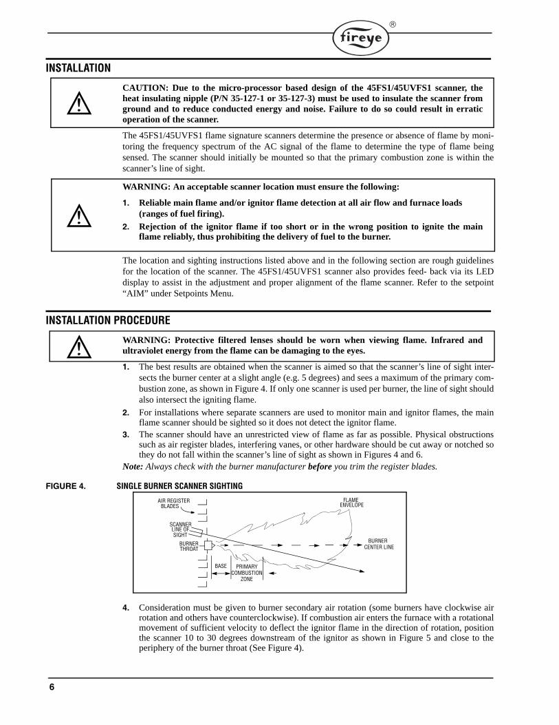
1. The best results are obtained when the scanner is aimed so that the scanner’s line of sight inter-sects the burner center at a slight angle (e.g. 5 degrees) and sees a maximum of the primary com-bustion zone, as shown in Figure 4. If only one scanner is used per burner, the line of sight shouldalso intersect the igniting flame.
2. For installations where separate scanners are used to monitor main and ignitor flames, the mainflame scanner should be sighted so it does not detect the ignitor flame.
3. The scanner should have an unrestricted view of flame as far as possible. Physical obstructionssuch as air register blades, interfering vanes, or other hardware should be cut away or notched sothey do not fall within the scanner’s line of sight as shown in Figures 4 and 6.
Note: Always check with the burner manufacturer before you trim the register blades.
FIGURE 4. SINGLE BURNER SCANNER SIGHTING
4. Consideration must be given to burner secondary air rotation (some burners have clockwise airrotation and others have counterclockwise). If combustion air enters the furnace with a rotationalmovement of sufficient velocity to deflect the ignitor flame in the direction of rotation, positionthe scanner 10 to 30 degrees downstream of the ignitor as shown in Figure 5 and close to theperiphery of the burner throat (See Figure 4).
PRIMARYCOMBUSTION
ZONE
AIR REGISTERBLADES
SCANNERLINE OFSIGHT
BURNERTHROAT
FLAMEENVELOPE
BURNERCENTER LINE
BASE

7
FIGURE 5. SCANNER LOCATION VS. SECONDARY AIR ROTATION
5. Having determined the approximate location for the sight pipe, cut a clearance hole for a 2 inchpipe through the burner plate. Look through the hole. If register vanes interfere with the desiredline of sight, the interfering vane(s) should be trimmed to assure an unrestricted viewing path at allfiring levels.
Note: Always check with the burner manufacturer before you trim register vanes.
FIGURE 6. FLAME MUST COMPLETELY COVER SIGHT OPENING
6. The preferred method for mounting surface mounted scanners requires the use of a swivel mount,P/N 60-1664-3 (NPT). Center the swivel mount over the two inch hole in the burner plate andsecure using three hexed cap screws (not provided). Install the sight pipe on the swivel mount. If aswivel is not used, insert the end of the sight pipe into the hole, align the hole to the desired view-ing angle and tack weld (welding must be adequate to temporarily support the weight of theinstalled scanner). The sight pipe should be arranged to slant downward so that dirt and dust willnot collect inside.
CAUTION: Use no more than one foot of one inch diameter sight pipe. Increase the sight pipediameter one inch for every additional foot of sight pipe length used to avoid restricting thescanner’s field of view.
Note: The 45FS1/45UVFS1 scanner provides feedback via its LED display to assist in the adjustmentand proper alignment of the flame scanner. Refer to the setpoint AIM under “Programming the FlameSignature Scanner” and the “Programming Primer” (Publication CU-33).7. When a satisfactory sighting has been confirmed by operational testing, secure the swivel mount’s
ball position in place by tightening the three hex head cap screws located on the swivel mount ring.8. For ease of use, the scanner should be installed on the sight pipe so the LED display can easily be
read. If this is not possible, install the scanner with the quick disconnect facing downward.Note: Operation of the LED display is independent of position.9. Due to the micro-processor-based design of the 45FS1/45UVFS1 scanner, the heat insulating nip-
ple (P/N 35-127-1 or 35-127-3) must be used to isolate the scanner from ground.
CAUTION: Due to the micro-processor based design of the 45FS1/45UVFS1 scanner, the heatinsulating nipple (P/N 35-127-1 or 35-127-3) must be used to insulate the scanner from groundand to reduce conducted energy and noise. Failure to do so could result in erratic operation ofthe scanner.
IGNITOR
SCANNER
MAINBURNER
CCW ROTATION
IGNITOR
SCANNER
MAIN
CCW ROTATION
BURNER
BUT THISNOT THIS NOT THIS

8
10. The scanner lens must be kept free of contaminants (oil, ash, soot, dirt) and the scanner temperaturemust not exceed its maximum rating of 150° F (65° C) for 45FS1 or 131°F (55°C) for 45UVFS1.Excessive temperatures will shorten scanner life. Both requirements will be satisfied by a continu-ous injection of purge air at either the 3/8” housing inlet or the 1” “Y” connection ahead of theswivel mount as shown in Figures 7 and 8.
Note: Internal scanner temperature is available via the LED display. See “Status Menu” under “Pro-gramming the Scanner.”
The scanner mounting may be made with provision for purge air through only the 3/8” opening asshown in Figure 9 or for purge air through either the 3/8” opening or the 1” “Y” connection as shown inFigure 8. In the latter arrangements, normally only one of the two connections is provided with purge airand the other connection is plugged. When a sealing coupling is used as shown in Figure 7, the 1” “Y”connection is used for the purge air and the 3/8” opening is plugged.
It is good practice to use the sealing coupling (P/N 60-1199-1 with NPT threads) on all installations toinsure against unwanted boiler pressures from damaging the scanner lens.
Under normal conditions, with clean burning fuels and moderate ambient temperature conditions, purgeair flow of approximately 4 SCFM (133L/min) is generally adequate. Up to 15 SCFM (425L/min) maybe required for fuels that produce high levels of ash or soot, or for hot environments to maintain thescanner’s internal temperature within specification. Flexible conduit should be used to wire the scannerfrom a grounded service box to the scanner.
FIGURE 7.
FIGURE 8.
PART NUMBER
A. SWIVEL MOUNT 60-1664-3 (NPT)60-1664-4 (BSP)
B. 1” WYE 35-200 (NPT)
C. 1” CLOSE NIPPLE 35-201 (NPT)
D. SEALING COUPLING W/QUARTZ WINDOW60-1199-1 (NPT)
60-1199-2 (BSP)
E. HEAT INSULATING NIPPLE 35-127-1 (NPT)35-127-3 (BSP)
F. 3/8” PLUG 35-202 (NPT)*NOTE: SCANNER SHOWN IN PHOTOGRAPH IS NOT A 45FS1 SIGNATURE SCANNER.
AB
C
D
E F
20" (500) MAX*
PART NUMBER
A. SWIVEL MOUNT 60-1664-3 (NPT)
60-1664-4 (BSP)
B. 1” WYE 35-200 (NPT)
C. HEAT INSULATING NIPPLE 35-127-1 (NPT)35-127-3 (BSP)
D. 3/8” PLUG 35-202 (NPT)A B C
D
18 3/4" (475) MAX*
*NOTE: SCANNER SHOWN IN PHOTOGRAPH IS NOT A 45FS1 SIGNATURE SCANNER.

9
FIGURE 9.
FIGURE 10.
USE OF SCANNER ACCESSORIES
Swivel Mount
The scanner swivel mount, P/N 60-1664-3 (NPT) (see Figure 10, Item A), is used to adjust the scan-ner sighting angle after the scanner has been installed, The swivel mount is used as indicated in Fig-ures 7, 8, and 9.
Heat Insulating Nipple
Heat Insulating nipple, P/N 35-127-1 (NPT), or P/N 35-127-3 (BSP) (see Figure 9, Item B), is used toprevent heat transfer from the hot sight pipe to the scanner head as well as electrically isolate thescanner from ground. The appropriate nipple (NPT or BSP) is shipped with the scanner.
Sealing Coupling with Quartz Window
The sealing coupling, P/N 60-1199 (see Figure 10, Item B), is used whenever a coupling or a seal isrequired for scanner piping. The quartz window blocks furnace pressure, heat gasses and soot fromcoming in contact with the scanner and contaminating the lens. The size is one inch U.S. standardtaper pipe thread (Schedule 40, 1” - 11 1/2 NPT). When the sealing coupling is used, a 1” “Y” fittingmust be used down stream of it for connection of a purge air supply (plug 3/8” opening). See Figure 7for piping with the sealing coupling, Item D.
PART NUMBER
A. SWIVEL MOUNT 60-1664-3 (NPT)60-1664-4 (BSP)
B. HEAT INSULATING NIPPLE 35-127-1 (NPT)35-127-3 (BSP)
C. 3/8” THREADED OPENING
A
BC
13" (330) MAX*
*NOTE: SCANNER SHOWN IN PHOTOGRAPH IS NOT A 45FS1 SIGNATURE SCANNER.
PART NUMBER
A. SWIVEL MOUNT 60-1664-3 (NPT)
SWIVEL MOUNT 60-1664-4 (BSP)
B. SEALING COUPLING W/QUARTZ WINDOW60-1199-1 (NPT)
60-1199-2 (BSP)
C. SCANNER CABLE 59-470, 59-471
C
B
A

10
ELECTRICAL ACCESSORIES
Scanner Cable (P/N 59-470)
The number of conductors required for wiring the 45FS1/45UVFS1 scanner to the associated ampli-fier is dependent on the functions utilized by the scanner. Fireye offers a six (6) conductor cable (P/N59-470) that can be used for most applications. The 59-470 cable is made up of four (4) #18 AWGconductors and two (2) #22 AWG conductors. All six wires are enclosed with a mylar tape wrapshield and drain wire. The cable jacket is made of Hypalon, with an overall outside diameter of .425"(max).
The Fireye scanner cable (59-470) is color coded as follows for connection to the quick disconnect ofthe 45FS1/45UVFS1 scanner or wiring harness (if required):
* RFS = Remote file select.
Scanner Cable (P/N 59-471)
Fireye offers an eight (8) conductor cable (P/N 59-471) that is used for remote communicationswhen the distance from the scanner to the amplifier is less than 200 feet. When the distance isgreater than 200 feet, the wiring harness (or equivalent) must be used for remote communications.The 59-471 cable is made up of four (4) #18 AWG conductors and four (4) #22 AWG conductors. Two ofthe 22 AWG wires are a twisted pair for remote communications. All eight wires are enclosed with amylar tape wrap shield and drain wire. The cable jacket is made of Hypalon, with an overall outsidediameter of .550" (max).
The Fireye scanner cable (59-471) is color coded as follows for connection to the quick disconnect ofthe 45FS1/45UVFS1 scanner or wiring harness (if required)
Note: Brown and orange wires are a twisted pair.Note: If you retrofit to older Fireye 4-conductor cable 59-221, connect the four wires (black, red,white, green) as shown above. Remote file select, and remote communications are not possible withthis cable.
59-470 Cable Color Function Pin Number of Quick Disconnect
Terminal Number of Scanner Harness
Black +24 VDC 1 1
Red Shutter 2 2
White Common
Green Flame Signal 3 3
Blue * RFS 1 5 5
Yellow * RFS 2 7 7
59-471 Cable Color Function Pin Number of Quick Disconnect
Terminal Number of Scanner Harness
Black +24 VDC 1 1
Red Shutter 2 2
White Common
Green Flame Signal 3 3
Blue * RFS 1 5 5
Yellow * RFS 2 7 7
Brown COM A 4 4
Orange COM B 6 6
* RFS = Remote file select.
11
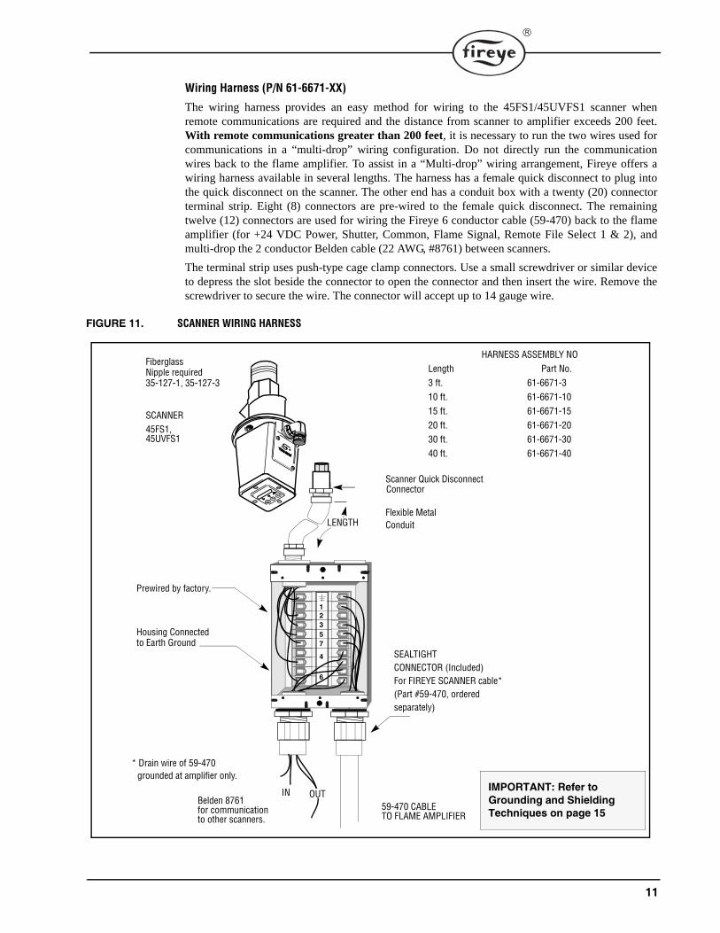
Wiring Harness (P/N 61-6671-XX)
The wiring harness provides an easy method for wiring to the 45FS1/45UVFS1 scanner whenremote communications are required and the distance from scanner to amplifier exceeds 200 feet.With remote communications greater than 200 feet, it is necessary to run the two wires used forcommunications in a “multi-drop” wiring configuration. Do not directly run the communicationwires back to the flame amplifier. To assist in a “Multi-drop” wiring arrangement, Fireye offers awiring harness available in several lengths. The harness has a female quick disconnect to plug intothe quick disconnect on the scanner. The other end has a conduit box with a twenty (20) connectorterminal strip. Eight (8) connectors are pre-wired to the female quick disconnect. The remainingtwelve (12) connectors are used for wiring the Fireye 6 conductor cable (59-470) back to the flameamplifier (for +24 VDC Power, Shutter, Common, Flame Signal, Remote File Select 1 & 2), andmulti-drop the 2 conductor Belden cable (22 AWG, #8761) between scanners.
The terminal strip uses push-type cage clamp connectors. Use a small screwdriver or similar deviceto depress the slot beside the connector to open the connector and then insert the wire. Remove thescrewdriver to secure the wire. The connector will accept up to 14 gauge wire.
FIGURE 11. SCANNER WIRING HARNESS
IMPORTANT: Refer to Grounding and Shielding Techniques on page 15
SCANNER45FS1,
Flexible MetalConduit
Scanner Quick DisconnectConnector
HARNESS ASSEMBLY NOLength Part No.3 ft. 61-6671-310 ft. 61-6671-1015 ft. 61-6671-1520 ft. 61-6671-2030 ft. 61-6671-3040 ft. 61-6671-40
SEALTIGHTCONNECTOR (Included)For FIREYE SCANNER cable*(Part #59-470, ordered separately)
* Drain wire of 59-470grounded at amplifier only.
FiberglassNipple required35-127-1, 35-127-3
Housing Connectedto Earth Ground
12357
4
6
Prewired by factory.
LENGTH
59-470 CABLETO FLAME AMPLIFIER
Belden 8761for communicationto other scanners.
IN OUT
45UVFS1

12
CONTROL AND SCANNER WIRING
CAUTION: The 45FS1/45UVFS1 flame scanner requires 24 VDC power for operation.Connection to a 24 VAC or 120 VAC power source will damage the scanner. Refer to wiringdiagrams.
All wiring to the scanner should be rated at 90°C. For runs less than 1000 feet, the use ofScanner Cable, P/N 59-470 (6 wire) is recommended. For runs in excess of 1000 feet, consultthe factory.
Note: Two (2) additional wires are required for remote communication.
To reduce electrical noise interference, the scanner cable should be installed in rigid or flexible con-duit. Take precautions to keep the scanner cable away from any high inductive wiring associatedwith high inductive loads or high voltage, high energy spark ignition systems. The quick disconnectkit (P/N 129-127-6) includes an adaptor for connection to a 1/2" flexible conduit.
QUICK DISCONNECT KIT P/N 129-127-6 (Ordered Separately)For ease of installation and removal, a quick disconnect is used with the 45FS1, 45UVFS1, 61-6625,61-6694 scanners. The male connector is factory mounted on the scanner. The female cable connec-tor kit, P/N 129-127-6, is ordered separately. This assembly procedure applies to Fireye six-conduc-tor cable (P/N 59-470), eight-conductor cables (P/N 59-471), and obsolete four-conductor cable (P/N 59-221).
The connector kit contains both a cord-grip strain relief fitting, and an adapter for use with 1/2" flex-ible conduit (refer to figure 16, options 1 and 2). The installer must select either one style fitting orthe other.
Referring to Figure 13, locate the end of the cable where the red wire is clockwise with respect to thewhite wire. For ease of assembly, this end should be connected to the scanner quick disconnect.
Refer to bulletin CU-56 for operation of the FS700W software and wiring to the IBM compatiblePC.
ASSEMBLY (Refer to Figure 14)1. Before stripping cable jacket, test the rubber cable seal for proper fit, (part of cable seal kit).
Depending on the cable used, it may be necessary to remove inner ring(s) to provide a snug fit.Set aside until step 8.
2. Strip the outer cable jacket 2 1/2 inch (64 mm).3. Trim insulated conductors to 1 3/8 inch (35 mm), leave the shield drain wire 2 1/2."4. Strip individual conductor insulation 5/16 inch (8 mm).5. Select either the Option #1 or the Option #2 fittings (see figure 16).
Option #1: Slide the cord-grip strain relief fitting onto the scanner cable. (The fitting containsan internal bushing suitable for Fireye six-conductor cable, p/n 59-470. If Fireye eight-conduc-tor cable is used, p/n 59-471, use the larger bushing provided in the kit). Option #2: Slide the PG16 to 1/2" Flexible Conduit Adapter and the PG11/PG16 thread adapteronto the scanner cable.
6. From the cable seal kit, install the first of two flat washers onto the cable.7. Fold the shield drain wire back along the cable outer jacket.8. From the cable seal kit, slide the rubber seal and second flat washer, (part of cable seal kit), onto
the cable over the shield drain wire. Leave the rubber seal on top of the end of the drain wireuntil step 15. Discard the nut from the cable seal kit.
9. Solder the female contacts onto the individual conductors, (use the least amount of solder).Install the smaller female contacts on the smaller 22 AWG scanner wires (blue, yellow, brown,orange) if used.
10. Install the connector hood on the cable, making sure the hood nut is removed.

13
11. Install the contacts into the female insert in the appropriate order. When properly installed, thecontacts will “click” into the insert. Verify by pulling slightly on each wire.
12. Place the threaded hood nut over the female insert.13. Slide the connector hood over the female insert, aligning the hood locating “key” with the wide
groove on the female insert.14. Tighten the threaded hood nut.15. Slide the second flat washer and the rubber seal into the connector hood. Push into place until
firmly seated.16. Wrap the shield drain wire around the cable jacket one turn only, (between the rubber seal and
the first washer, wrapped clockwise as viewed from the conduit or strain relief adapter), and trimany excess length.
17. Slide the first flat washer into the connector hood, on top of the drain wire.18. Thread either the Option 1 or Option 2 fittings and tighten firmly to properly compress the rub-
ber seal. This also compresses the first washer against the drain wire, electrically connecting theshield to the connector hood. Torque to 35 inch pounds.
Before applying power, perform a continuity check on each conductor to confirm proper assembly.Confirm that you have continuity between the cable shield (at the amplifier end of the cable) and thequick disconnect hood (metal housing).
FIGURE 12. QUICK DISCONNECT TERMINALS
FIGURE 13. FOR EASE OF CONNECTOR ASSEMBLY, INSTALL ON END SHOWN
3GREEN
RED
WHITE
FLAME SIGNAL
SHUTTER
COMMON
+24VDC
16
5
234
59-470
LEADS 7
1
2
BLACK
YELLOW
BLUE RFS1 * (REMOTE FILE SELECT)
RFS2 * (REMOTE FILE SELECT)
5
7
ADDITIONAL 4BROWN COM A *
6ORANGE COM B *
and 471
59-471LEADS
WIRE COLOR PIN FUNCTION
* USE THE SMALLER OF THE FEMALE CONTACTS FOR THESE FOUR 22 AWG WIRES.
RD
YL GN
WT
BU
BK
RD
YL
WT
BU
BK
AMPLIFIER END SCANNER ENDCABLE
P/N 59-470 SHOWN
GN

14
FIGURE 14.
Note: Refer to Figures 19, 20, and 21 for proper wiring of the scanner cable to the appropriate controls.
FEMALE CONTACTCABLE
HOOD
FEMALE
1.375"
2.50" (64mm)SHIELD DRAIN WIRE
(35mm)
1.375"(35mm)
WASHER RUBBER WASHER
CABLE SEAL KIT
STRIP 5/16" (8mm)FROMINDIVIDUALWIRES
59-471ONLY
PG11/PG16 ADAPTER
PG16 TO 1/2" FLEXIBLE CONDUIT ADAPTER INSERT
HOODNUT
SEAL
SEAL KIT
PG11/PG16 ADAPTER
NOTE 2: THE NUT FROM THE CABLE SEAL KIT IS NOT USED.NOTE 3: REMOVE INNER RING(S) FROM RUBBER SEAL FOR PROPER FIT ONTO CABLE. NOTE 4: WRAP DRAIN WIRE 1 TURN CLOCKWISE AROUND CABLE JACKET.
PG16 TO 1/2" FLEXIBLE CONDUIT ADAPTER
ALTERNATE BUSHING FOR STRAIN RELIEF
CORD GRIPSTRAIN RELIEF
OPTION 1
OPTION 2
ALTERNATE BUSHING FOR STRAIN RELIEF
CORD GRIPSTRAIN RELIEF
OPTION 1
OPTION 2
(Notes 2, 3)
NOTE 1: SELECT EITHER OPTION 1 OR OPTION 2 FITTINGS.
NOTE 5: OPTION #1: THE CORD GRIP STRAIN RELIEF CONTAINS A BUSHING SUITABLE FOR FIREYE 59-470 CABLE
(Note 1)
(Note 4)SHIELD DRAIN WIRE
(0.375”- 0.438” O.D.). IF FIREYE 59-471 CABLE IS USED, SUBSTITUTE THE ALTERNATE BUSHING (0.500”- 0.562” O.D.).TORQUE TO 35 INCH POUNDS.
(Note 5)

15
GROUNDING AND SHIELDING TECHNIQUESFOR USE ON SCANNERS OR SCANNER CABLE LOCATED WITHIN 12" OF A HIGHENERGY OR HIGH VOLTAGE SOURCE.
1. The scanner and scanner cable (preferably within flexible conduit) MUST be located at least onefoot (1') from the ignition source.
2. Run a ground wire from the ignition transformer chassis to the ignitor assembly.3. Replace all frayed, cracked, or dirty (oily) ignition wire. Ignition wire must be in good working
condition.4. Electrically isolate the scanner from the burner using a heat insulating nipple provided with the
scanner, (P/N 35-127-1 or 35-127-3).Note: If purge air is required, PURGE AIR must be electrically isolated from the scanner (e.g. iso-lated short rubber hose).5. IMPORTANT: The shield from EACH INDIVIDUAL WIRING RUN (e.g. scanner to
flame amplifier, or flame scanner to computer for RS485 communications). MUST BEGROUNDED AT ONE END ONLY. See below for shielding techniques based on the vari-ous scanner wiring configurations.
SCANNER TO AMPLIFIER SHIELDING TECHNIQUES45FS1/45UVFS1 with scanner cable (59-470) directly back to amplifier. See below for remote communications.
Attach drain wire to scanner quick disconnect as described. Use heat insulating nip-ple on scanner. Connect drain wire of 59-470 to earth ground at amplifier.
61-6625/61-6694 (fiber optic version) with scanner cable (59-470) directly back to amplifier. See below for remote communications.
Do not connect drain wire to scanner quick disconnect. Connect drain wire of 59-470 to earth ground at amplifier. If communication problems arise, install nylon scanner mounting screws (1/4 -20 x 1 1/4") attaching the scanner to the inner carrier assem-bly and connect drain wire to scanner quick disconnect.
45FS1/45UVFS1 or fiber-optic version with wir-ing harness or junction box and scanner cable (59-470) directly back to amplifier. See below for remote communications.
Attach drain wire to scanner quick disconnect as described. Use heat insulating nip-ple on scanner. (Does not apply to fiber optic version). Connect 59-470 shield to har-ness shield at wiring harness or junction box. Connect drain wire to earth ground at amplifier.
REMOTE COMMUNICATIONS: LESS THAN 200 FEET45FS1/45UVFS1 with scanner cable (59-471) directly back to amplifier.
Attach drain wire to scanner quick disconnect as described. Use heat insulating nip-ple on scanner. Connect drain wire of 59-471 to earth ground at amplifier.
61-6625/61-6694 (fiber optic version) with scanner cable (59-471)directly back to amplifier.
Do not connect drain wire to scanner quick disconnect. Connect drain wire of 59-471 to earth ground at amplifier. If communication problems arise, install nylon scanner mounting screws (1/4 -20 x 1 1/4") attaching the scanner to the inner carrier assem-bly, and connect drain wire to scanner quick disconnect.
REMOTE COMMUNICATIONS: GREATER THAN 200 FEETRS485 communications for 45FS1/45UVFS1 scanners or fiber optic version wired in a multi-drop configuration (Belden 8761) using wiring harness or junction box.
Attach drain wire to scanner quick disconnect as described. Use heat insulating nip-ple on scanner (does not apply to the fiber optic version). Connect drain wire of 59-471 to earth ground at amplifier. Twist together and tape (to electrically isolate) drain shields from Belden 8761 cables inside each wiring harness or junction box. Con-nect shield drain to earth ground at RS485 source (e.g. IBM computer).

16
WIRING FOR REMOTE COMMUNICATIONS:Remote communications with the 45FS1/45UVFS1 scanner uses an RS485 Interface to carry thecommunication signals. An IBM compatible PC running the communication software is required tocommunicate with the 45FS1/45UVFS1 scanners. The wiring configuration for remote communi-cations is dependent on the distance between the scanner and amplifier. For distances less than200 feet, wire the Fireye cable 59-471 to the female quick disconnect in the following manner andrun the cable directly back to the flame amplifier.
Note: Brown and orange wires are a twisted pair.
For wiring distances greater than 200 feet, remote communications requires wiring a twisted,shielded pair of wires in a “multi-drop” wiring configuration, and then use a terminating resistor atthe scanner located farthest from the communication source. See “Using Fireye Wiring Harness.”
Note: The maximum distance for the communication wiring for all associated 45FS1/45UVFS1scanners is 4,000 feet. The maximum number of scanners connected to the communication link is 32scanners. Exceeding this total wiring length or number of scanners requires the installation of bi-directional repeaters or amplifiers. Consult factory for additional information.
Note: Refer to bulletin CU-56 for operation of the FS700W communication software and wiring tothe IBM compatible PC.
Using Fireye Wiring Harness (P/N 61-6671 -3, -10, -15, -20, -30)
To provide an easy method to wire the 45FS1/45UVFS1 scanners in a “Multi-drop” wiring configu-ration for remote communications, Fireye offers a wiring harness in 5 different lengths (3’,10', 15',20', and 30'). The harness has a pre-wired female quick disconnect to plug into the quick disconnecton the scanner. The other end of the wiring harness has a conduit box with a 18 connector terminalstrip. Eight (8) connectors are pre-wired to the female quick disconnect. The remaining ten (10) con-nectors are used for wiring the Fireye 6 conductor cable (59-470) back to the flame amplifier (for+24 VDC Power, Shutter, Common, Flame Signal, Remote File Select 1 & 2), and multi-drop the 2conductor Belden cable (22 AWG, #8761) between scanners and finally back to the communicationsource to complete the “Multi-drop” wiring configuration. The terminal strip inside the conduit boxshould be wired in the following manner:
59-471 Cable Color Function PIN Number of Quick Disconnect Black +24 VDC 1Red Shutter 2
White Common Wire directly to flame amplifierGreen Flame Signal 3Blue RFS 1 5
Yellow RFS 2 7Brown COM A 4 Wire to IBM PCOrange COM B 6
Cable Color Function Wiring Harness Wire cable
59-470Cable
Black +24VDC 1
Back to Flame Amp
Red Shutter 2White Common
Green Flame Signal 3Blue RFS1 5Yellow RFS2 7
Belden 8761 Black RS485 COM A 4To next flame scannerClear RS485 COM B 6
Belden 8761 Black RS485 COM A 4 To previous flame scanner (or EC485 converter)Clear RS485 COM B 6

17
FIGURE 15. SUGGESTED WIRING FOR 45FS1/45UVFS1 COMMUNICATIONS
FIGURE 16. WIRING DIAGRAM FOR WIRING HARNESS
Using Local Junction Box:
To provide remote communications without using the Fireye Wiring Harness, it is necessary to runthe Fireye eight (8) conductor cable (59-471) a short distance from the scanner to a junction box.From the junction box, wire the Fireye 59-470 cable back to the appropriate amplifier. Then wireBelden 8761 (22 AWG, twisted shielded pair wire) between each junction box and finally back to thecommunication source to complete the “Multi-drop” wiring configuration.
To ControlRoom 59-470
To ControlRoom 59-470
12357
4
6
Flex Conduit to Scanner
RS485 COMMUNICATIONS
BELDEN #8761(Twisted, shieldedpair)
To ControlRoom 59-470
Flex Conduit to Scanner
Flex Conduit to Scanner
12357
4
6
12357
4
6
RS485 communi-cation; For each individual wiring
run, connect shields together. Connect one end of the shield cir-cuit to ground.
Tape and isolate other end. See
1 2 3 5 7 4 6
COMMON — WHITE
+24VDC — BLACK
SHUTTER — RED
COM B — ORANGE
COM A — BROWN
RFS2— YELLOWRFS1— BLUE
SIGNAL — GREEN
WHITE
BLACKRED
YELLOWBLUE GREEN
59-470
COM A
COM B
COM B
COM A
BELDEN8761
TO CONTROLROOM
TO FLAMESCANNER
1. CONNECT SHIELDS TOGETHER
1. CONNECT SHIELDS
2. CONNECT SHIELD TO EARTH GROUND AT ORIGIN. (FIRST HARNESS OR PC)
TO PREVIOUS SCANNER, OR
TO NEXTSCANNER
TOGETHER.2. TAPE SHIELD AT
LAST WIRING HARNESS
(prewired byfactory)
CLEAR
BLACK
CLEAR
BLACK
CONNECT SCANNER SHIELDS TOGETHER AND GROUND ATAMPLIFIER.
EC485 CONVERTER.

18
FIGURE 17. WIRING FOR REMOTE FILE SELECT AND/OR REMOTE COMMUNICATIONS USING LOCAL ELECTRICAL JUNCTION BOX
FIGURE 18. WIRING FOR REMOTE COMMUNICATIONS
1 BLACK
WHITE
2 RED
3 GREEN
5 BLUE
7 YELLOW
4 BROWN
6 ORANGE
+24VDC
COMMON
SHUTTER
FLAME SIGNAL
RSF 1
RFS 2
COM A
COM B
BLACK
WHITE
RED
GREEN
BLUE
YELLOW
BROWN
ORANGE
BLACK
WHITE
RED
GREEN
+ 24VDC
COMMON
SHUTTER
SIGNAL
RFS1
RFS2
COM A (BLACK)
FROM PREVIOUS45FS1/45UVFS1 SCANNER
TO NEXT45FS1/45UVFS1 SCANNER
BELDEN8761
TO FLAMEAMPLIFIER
59-470
BLUE
YELLOW
59-471QUICK DISCONNECT PINSOF 45FS1/45UVFS1
1. CONNECT SHIELDS TOGETHER.2. TAPE SHIELD AT1. CONNECT SHIELDS
TOGETHER.2. CONNECT SHIELD TO
GROUND AT ORIGIN (EC485 OR PC).
CONNECT SCANNER SHIELDS TOGETHER AND GROUND ATAMPLIFIER.
LAST JUNCTION BOX.
COM B (CLEAR)
59-471CABLE
59-471CABLE
AMPLIFIER
BELDEN 8761
AMPLIFIER
BELDEN 8761
59-471
AMPLIFIER
IBM PC WITHFS700/FS700W
1. DISTANCE FROM SCANNER TO AMPLIFIER < 200 FEET.
2. DISTANCE FROM SCANNER TO AMPLIFIER >200 FEET.
AMPLIFIER AMPLIFIER
BELDEN 8761
AMPLIFIER
IBM PC WITHFS700/FS700W
BELDEN 8761
59-470
BELDEN 8761 BELDEN 876161-6671-XWIRINGHARNESS
REFER TO BULLETIN CU-39 (FS700) OR CU-56 (FS700W) FOR DETAILED WIRING CONNECTIONS
RS485COM ACOM B
SOFTWARE
SOFTWARE
CABLE
CABLE59-470CABLE
59-470CABLE
RS485-RS232CONVERTER, P/N EC485
RS485-RS232CONVERTER, P/N EC485OR P/N IC485
OR P/N IC485

19
FIGURE 19. WIRING COMBINATIONS TO P/N 60-1706 WIRING RACK TERMINALS USING 59-470 CABLE FOR THE FOLLOWING FLAME AMPLIFIERS: TYPE 25SU3, MODEL 4170, 4171, 5172, 5173 (or 25SU3-2000, -2100 with 192SU3 adapter)
General Notes:
1. Connect the scanner cable’s shield to the earth ground terminal at the control end only; the shield atthe scanner end should be attached to female quick disconnect housing.
2. Flame amplifier rack, P/N 60-1706, has a blocking diode between terminals 14A and 14D.3. Tape the shield at the 45UV5, 45RM1, 45RM2 scanner end.4. Fireye recommends the use of shielded cable for the two remote file select switches (or relays). These
controls should be rated for low current (3mA) operation.5. Cables 59-470 and 59-471 have overall shields. For illustration purposes, the shield is shown
only on the signal (green) conductor, as was the case on the obsolete cable 59-221.
1A
60-1706FM3
C14A
2
1
3
(SHUTTER)(+24VDC)
(COMMON)
1B
60-1706
FM3
C14A
(SIGNAL)
1A
14B
(SIGNAL)
1B
60-1706
FM3
C
14A
WIRING TERMINALS1
L or P *
14
(COMMON)
(SHUTTER)
(POWER)
C
** 14B or 14D
1A
LB
2
1
3
FEMALEQUICK-DISCONNECTFOR 45RM4
FOR 45UV5 OR45RM1 OR 45RM2
* POWER TERMINAL FOR 45UV5 = LPOWER TERMINAL FOR 45RM 1 OR 45RM2 = P
** WIRE TO TERMINALS 14B FOR FLAME AMPLIFIERS TYPE 25SU3, MODEL 5172, 5173WIRE TO TERMINALS 14D FOR FLAME AMPLIFIERS TYPE 25SU3, MODEL 4170, 4171, 4172.
GREEN
RED
BLACK
WHITE
SHIELD
SHIELD
SHIELD
SHIELD
SHIELD
RED
BLACK
WHITE
GREEN
RED
BLACK
GREEN
GREEN
WHITE
WHITE
GREEN
BLACK
RED
60-1706W
5 RFS1 - (OPTIONAL)BLUE
BLUE
BLUE
YELLOWRFS2 (OPTIONAL)7
YELLOW
YELLOW
WIRING HARNESS
7
5
2
1
3
FEMALE QUICK DISCONNECTOF 45FS1/45UVFS1
21
3
(SHUTTER)(+24VDC)
(COMMON)
(SIGNAL)
5 RFS1 - (OPTIONAL)
RFS2 (OPTIONAL)7
WIRING HARNESS
7
5
2
1
3
FEMALE QUICK DISCONNECT 45FS1/45UVFS1
21
3
(SHUTTER)(+24VDC)
(COMMON)
(SIGNAL)
5 RFS1 - (OPTIONAL)
RFS2 (OPTIONAL)7WIRING HARNESS
7521
3
FEMALE QUICK DISCONNECTOF 45FS1/45UVFS1
CONNECTOR HOUSING
CONNECTOR HOUSING
CONNECTOR HOUSING
CONNECTOR HOUSING
(NOTE 3)
(NOTE 5)
(NOTE 5)

20
FIGURE 20. WIRING COMBINATIONS TO 60-2206-1 AND 60-2206-2 WIRING BASE USING 59-470 CABLE FOR THE FOLLOWING FLAME AMPLIFIERS: TYPE 25SU5, MODEL 5011, 5012 (60-2206-1) and TYPE 25SU3, MODEL 5166, 5168 (60-2206-2)
1. For 45FS1/45UVFS1/45RM4 scanners, connect the scanner cable’s shield to the earth ground ter-minal at the control end only. The shield at the scanner end should be connected to female quick-disconnect housing.
2. For 45UV5/ 45RM1/ 45RM2 scanners, connect the scanner cable’s shield to the earth ground ter-minal at the control end only. The shield at the scanner end should be taped and isolated.
3. Fireye recommends the use of shielded cable for the two remote file select switches (or relays).These controls should be rated for low current (3mA) operation.
4. Cables 59-470 and 59-471 have overall shields. For illustration purposes, the shield is shownonly on the signal (green) conductor, as was the case on the obsolete cable 59-221.
160-2206-1 20
C14
26
20
C14
1
(SIGNAL)
26
20
C
14
WIRING TERMINALS1
L or P *
14
(COMMON)
(SHUTTER)(POWER)
C
1
LB
2
1
3
FEMALEQUICK-DISCONNECTFOR 45RM4
FOR 45UV5 OR45RM1 OR 45RM2
* POWER TERMINAL FOR 45UV5 = LPOWER TERMINAL FOR 45RM 1 OR 45RM2 = P
** DIODE (P/N 101-78) IS NOT REQUIRED WHEN USING 45RM1 OR 45RM2 SCANNERS
GREEN
RED
BLACK
WHITE
SHIELD
SHIELD
SHIELD
SHIELD
RED
BLACK
WHITE
GREEN
RED
BLACK
GREEN
GREEN
WHITE
WHITE
GREEN
BLACK
RED
60-2206W
60-2206-2
60-2206-1
60-2206-2
60-2206-1
60-2206-2
**
or
or
or
BLUE
BLUE
BLUE
YELLOW
YELLOW
YELLOW
21
3
(SHUTTER)(+24VDC)
(COMMON)
(SIGNAL)
5 RFS1 - (OPTIONAL)
RFS2 (OPTIONAL)7
WIRING HARNESS
7521
3
FEMALE QUICK DISCONNECTOF 45FS1/45UVFS1
21
3
(SHUTTER)(+24VDC)
(COMMON)
(SIGNAL)
5 RFS1 - (OPTIONAL)
RFS2 (OPTIONAL)7
WIRING HARNESS
7521
3
FEMALE QUICK DISCONNECTOF 45FS1/45UVFS1
21
3
(SHUTTER)(+24VDC)
(COMMON)
(SIGNAL)
5 RFS1 - (OPTIONAL)
RFS2 (OPTIONAL)7
WIRING HARNESS
7521
3
FEMALE QUICK DISCONNECTOF 45FS1/45UVFS1
CONNECTOR HOUSING
CONNECTOR HOUSING
CONNECTOR HOUSING
CONNECTOR HOUSING
(NOTE 4)

21
FIGURE 21. WIRING TO 25SU3-2100 AMPLIFIER RACKS USING 59-470 OR 59-471 CABLE
REMOTE FILE SELECTOR SWITCHESTwo (2) remote file selector switches can be wired into the 45FS1/45UVFS1 to select one of fourfiles (A, B, C, and F) containing flame signature information to be used as the reference file. Files A,B, and C store “learned” flame information and File F is the default flame signature. The setpointRFS must be programmed ON for the remote file selector switches to be operational. SeeRemote File Select (RFS) under “Setpoints Menu.” With the setpoint RFS to be programmed “ON,”the status of switches RFS1 and RFS2 will determine which file is selected in the following manner:
RFS2(Yellow)
RFS1(Blue)
FILE
Open Open AOpen Closed B
Closed Open CClosed Closed F
D625SU3-2100
D8
D4 or D12 or D30D2 GREEN
RED
BLACK
WHITE
BLUE
YELLOW
21
3
(SHUTTER)(+24VDC)
(COMMON)
(SIGNAL)
5 RFS1 - (OPTIONAL)
RFS2 (OPTIONAL)7
WIRING HARNESS
7521
3
FEMALE QUICK DISCONNECTAT 45FS1/45UVFS1
CONNECTOR HOUSING
SHUT A24V
COM
SIG A
CONNECTOR TERMINALS FOR 60-2471-1 HALF RACK OR 60-2471-3 FULL RACK
TERMINALS WITHIN60-2530 SURFACE MOUNTWIRING RACK
4
6
D32 or Z32 SHIELD
4
6
“A” “B”COMMUNICATIONS(Cable 59-471 only)
BROWN
ORANGE
BROWN
ORANGE
COM “A”COM “B”
COM “A”
COM “B”
SHIELD
25SU3-2100
GREEN
RED
BLACK
WHITE
BLUE
YELLOW
21
3
(SHUTTER)(+24VDC)
(COMMON)
(SIGNAL)
5 RFS1 - (OPTIONAL)
RFS2 (OPTIONAL)7
WIRING HARNESS
7521
3
FEMALE QUICK DISCONNECTAT 45FS1/45UVFS1
CONNECTOR HOUSING
4
6
4
6
“A” “B”COMMUNICATIONS(Cable 59-471 only)

22
Note: With the setpoint RFS programmed ON and no wires or switches wired into the scanner, the45FS1/45UVFS1 will use File A (RFS1 and RFS2 are both Open).
A third selection for the setpoint RFS is COMM. With this selection, the file is selected via remotecommunication. Refer to Communications Address under Status menu.
Fireye recommends the use of shielded cable for the two remote file select switches (or relays).These controls should be rated for low current (3mA) operation.
PROGRAMMING THE FLAME SIGNATURE SCANNER
Keypad/Display:The 45FS1/45UVFS1 Flame Signature Scanner uses an eight (8) character, alphanumeric, Light Emit-ting Diode (LED) Display and three (3) push-button to review and program the various setpoints andoperating parameters. The functions of the push-button are:
Advance (➡) This allows the user to review each of the various setpoints and operating parametersassociated with the scanner. Each time this key is pressed, the display will advance to the next setpointor system status.
Help (?) - System status and setpoints use mnemonic abbreviations. This key will display the meaningand full length descriptor of the mnemonic.
Change (▲) This allows the user to modify the various setpoints and operating parameters. The Pro-gram Enable button must initially be pressed before the Change Key will operate.
Program Enable Button:
The Program Enable button is a red push-button located by removing the metal cover behind the quickdisconnect. THIS BUTTON MUST BE PRESSED TO ENTER THE PROGRAM MODE, DIS-PLAY THE SETPOINTS MENU, AND ENABLE THE CHANGE KEY (▲). Once this button ispressed, the Change key (▲) can be used to modify the various setpoints. The Program Enable buttonis also needed to execute the Edit, Learn On New/Add, Learn Off New/Add, Aim, Save, Run, andAbort operations. (See Setpoints Menu). If no key is pressed for a time period of twenty (20) min-utes, the scanner will exit the Program Mode and the Change key will be disabled. The ProgramEnable button must be pressed again to continue programming.
Status and Setpoint Menu
The 45FS1/45UVFS1 scanner has two levels of menus; one to display the current status of the flamescanner and monitored burner, and the other to display the various system setpoints. The status menuis for review only. The system setpoints menu is used to setup the operating parameters for a particulartype of burner, fuel type, flame signature, etc. (See Programming Setpoints). The Advance Key (➡)scrolls through the menus. The system setpoints menu is displayed by pressing the Program Enablebutton.

23
Status Menu
Setpoint Menu
MNEMONIC CODE DESCRIPTION ALLOWABLE VALUES
Flame Off The status of the monitored flame. Flame On/Off
FQ = 0 Flame quality 0-100
T = 43 C Internal flame scanner temperature XX = °F or XX = °C
FILE =F Reference flame data file A, B, C, F, (:), (*) (See NOTE below)
DISCR = 9 Flame on/off discrimination ratio. 0 -9
COMM = 0 Communication Address 0 -127
Scanner Message Will display any scanner messages, errors, or revision number. See “Scanner Messages”
NOTE: A*, B*, C*, or F* is displayed when reference flame signature profile is selected via the remote file selector switch. See RFS under Sys-tem Setpoints.A: B: C: F: is displayed when reference flame signature profile is selected via remote communications.
MNEMONIC CODE DESCRIPTION ALLOWABLE VALUES
EDIT = YES Edit a File YES/NO
EDIT = A Select a file to edit. A, B, C, F
COMM = 0 Communication Address. 0-127
FFRT = 3 Flame failure response time. 1-6 seconds
BFRT= 3 Background failure response time. 2-8 seconds (must be greater than or equal to FFRT)
OTD = 2 On time delay. 2-4 seconds
TEMP = C Internal scanner temp. displayed. Fahrenheit or Celsius
F = GAS Type of Fuel. Gas, Other, Oil, Coal
B= OFF Type of burner. Off, Mech, Gun, LowNox, Cane, Ring, Bucket, Grate, Other.
AMP = 5000 Type of amplifier. Series 5000, R900, 2000, 4000,
RFS = OFF Remote file select. OFF, ON, COMM
AIM = 60 Scanner sighting aid. Not programmable.
L ON NEW (or ADD) Learn a NEW (or ADD to an existing) Flame On sig-nature.
NEW, ADD
L OFF NEW (or ADD) Learn a NEW (or ADD to an existing Flame Off sig-nature.
NEW, ADD
SAVE@A Save the flame signature to a file. File A, B, or C.
RUN A Run the flame signature in a file. File A, B, C, or F.
ABORT Abort program mode (Return to status menu). Not programmable.

24
STATUS MENU LOOP (Except for temperature, all values shown are factory default setting)
STATUS MENUFollowing is a detailed description of each menu item:
Flame On/Off - Indicates whether or not the 45FS1/45UVFS1 scanner has detected the monitoredflame.
Flame Quality (FQ) - Indication as to how close a match the signature of the monitored flame is tothe parameters of the reference signature. The higher the number, the closer the parameters arematched. When the flame quality is 60 or above, the scanner Interprets a flame-on condition. Whenthe flame quality is 40 or below, the scanner interprets a flame-off condition.
Internal Scanner Temperature (T) - Readout scanner temperature. Max. operating temperature for45FS1 is 150F (65C). For 45UVFS1 the maximum operating temperature is 131F (55C). Thetemperature will display in either Fahrenheit or Celsius. Indication (F or C) is selected in Setpointsmenu.
Reference Flame File (FILE) - Indicates the flame signature file the scanner is comparing the mon-itored burner against. Four (4) files are available for selection: A, B, C, or F. F represents the factorydefault values. When the reference profile is selected via the remote file selection switch 1, an aster-isk will follow the letter (e.g. A* or C*). When the reference profile is selected via remote communi-cations2, a colon will follow the letter (e.g. A: or C:). The parameters for each reference signature isprogrammed in the Setpoints menu.
MNEMONIC CODE DESCRIPTION ALLOWABLE VALUES
Flame OFF The status of the monitored flame Flame on/Flame off
FQ = 0 Flame quality 0-100
T = 43 C Internal flame scanner temperature Celsius or Fahrenheit
FILE = F Reference flame signature file A, B, C, F, ( : ), (*)
DISCR = 9 Flame on/ flame off discrimination ratio 0-9
COMM = 0 Communication Address 0-127
Scanner Messages Will display any scanner messages, errors, or revision number.
See “Scanner Messages”
1. The Remote File Selector Switch must be programmed “ON” (See RFS under Setpoints Menu).2. RFS must be programmed “COMM” (see RFS under Setpoints).
T=43C
FILE = F
COMM = 0
DISCR = 9
SCANNERMESSAGES
FLAME = OFF
FQ=0
START HERE
?Advance (Advances menu)
Help (Scrolls descriptor)
Change (Not functional in status loop)
Keypad Legend
25
Discrimination (DISC) - Indication of the quality of discrimination obtained from the LearnedFlame On and Learned Flame off profiles. This menu item is very useful. During the setup proce-dure, the user should try to maximize this value. Allowable values are 0 to 9. Value should be at least5 or higher for discrimination to occur. The larger the number, the better the discrimination.
Note: Since this setpoint depends on both the Flame On and Flame Off profiles, an incorrect valuefor this setpoint will be displayed until both the Learn Flame On and Learn Flame Off proceduresare completed. The only exception would be a single burner application where the Flame Off condi-tion is a black boiler.
Communication Address (COMM) - Displays the address of the scanner for remote communica-tion to an IBM compatible PC. The available selections are 0 -127.
Scanner Messages - See “Scanner Messages” later in this document.

26
SETPOINT MENU LOOP (All values shown are factory default setting)
STATUS MENULOOP
FFRT = 3BFRT = 3OTD = 2TEMP = CF = GASB = OFFAMP = 5000RFS = OFF
PRUN A
P
EDIT A
P
AIM = 60
L ON NEW
L OFF NEW
SAVE @ A
ABORT
GAIN CAL
LEARNINGFLAME ON
P
P
P
P
P
EDIT N
COMM = 0
LEARNINGFLAME OFF
ABORT P
YES NO
ADVANCE KEYREQUIRED TOSCROLL THROUGH
(NOTE 1)
(NOTE 2)
(NOTE 2)
(NOTE 3)
NOTES:1. DEPRESS ▲ (CHANGE) KEY TO
SELECT “YES.”2. DEPRESS ▲ (CHANGE) KEY TO
SELECT “ADD.”3. DEPRESS ▲ (CHANGE) KEY TO
SELECT “B” and “C.”
?Advance (Advances menu)
Help (Scrolls descriptor)
Change (Not functional in status loop)
Keypad Legend
P Program Enable (Executes commands)

27
SETPOINT MENU LOOP (continued)
SETPOINTS MENUEDIT Y/N - This is the first prompt displayed once the program enable button is pressed inorder to put the scanner in the Programming Menu. The change key (▲) will toggle betweenEDIT YES and EDIT NO. If EDIT NO is displayed, the Advance Key (➡) will then display theRUN A (or appropriate file) command. If EDIT YES is displayed, the Advance Key (➡) willthen display the EDIT A (or appropriate file) command.
EDIT A - This prompt selects the file to edit or modify. Allowable values are A, B, C, or F. The Pro-gram Enable button is required to advance to the various setpoints. The Advance key will again dis-play EDIT Y/N.
Communication Address (COMM = 1) - The address of the scanner for remote communications toan IBM compatible PC. The available selections are 0-127. No two scanners on the same commu-nication data link can have the same address.
Flame Failure Response Time (FFRT) - Response time in the event the monitored flame goes froma Flame On to a total flame out (black boiler) condition. Allowable values are from 1 to 6 seconds.
CAUTION: The FFRT time of the 45FS1/45UVFS1 is ADDED to the FFRT time of theflame amplifier to determine total FFRT timing. For example, if the FFRT timing on25SU3-5011 is set at 1 second and the FFRT of 45FS1/45UVFS1 is set at 3 seconds, then thetotal FFRT timing is 4 seconds.
MNEMONIC CODE DESCRIPTION ALLOWABLE VALUES
EDIT N Edit a file Yes, No (Note 1)
EDIT A Select the file to edit A, B, C, F
COMM = 0 Communication Address 0 - 127
FFRT = 3 Flame failure response time 1-6 seconds
BFRT = 3 Background failure response time 2-8 seconds (Note 2)
OTD = 2 On time delay 2-4 seconds
TEMP = C Temp displayed in Celsius (or Fahrenheit) Celsius or Fahrenheit
F = GAS Type of fuel Gas, other, oil, coal
B = OFF Type of burner Off, mech, gun, lownox, cane, ring, bucket, grate, other
AMP = 5000 Type of amplifier Series 5000, R900, 2000, 4000 amplifiers
RFS = OFF Remote file select Off, On, Comm
(Last six functions require activation of button to execute: Aim - Abort)
AIM = 60 Scanner sighting aid
L ON NEW Learn a new flame-on signature (Note 3)
L ON ADD Learn and add to an existing flame-on signature
L OFF NEW Learn a new flame-off signature (Note 3)
L OFF ADD Learn and add to an existing flame-off signature
SAVE@A Save the flame signature to a file File A, B, or C (Note 4)
RUN A Run the flame signature in a file File A, B, C, or F (Note 5)
ABORT Abort program mode; return to Status Menu
1. Depress ▲ (change) to select “yes”2. BFRT cannot be set less than FFRT.3. Depress ▲ (change) to select “ADD.”4. Depress ▲ (change) to select “B, C”5. Depress ▲ (change) to select “B, C, F.”

28
Background Failure Response Time (BFRT) - Response time in the event the monitored flamegoes from a “flame on” to a flame out condition with background flame signal (e.g. fireball). Allow-able values are 2 to 8 seconds. The values for BFRT must be the values for FFRT.
Note: See “Learn Flame On New” Caution, page 29.
On Time Delay (OTD) - Response time on start up for the 45FS1/45UVFS1 scanner to detect a“flame on” condition before allowing the flame amplifier to pull in the flame relay (e.g. 45FS1/45UVFS1 will not allow pulses to the flame amplifier until a “flame on” condition has been detectedfor the programmed time). Allowable values are 2 to 4 seconds.
Type of Fuel (F) - In determining the flame signature profile of the monitored burner, programmingthe type of fuel helps “fine tune” the signature profile. This selection affects how the scannerresponds to the low frequency characteristics of the flame. Selections are gas, oil, coal, and other.Other fuel type selections can be tried to determine if Discrimination (DISC on Status menu) isimproved. (e.g. rice hulls may provide the highest discrimination if “Coal” is selected).
Note: See “Learn flame on new” page 29.
Type of Burner (B) - In determining the flame signature profile of the monitored burner, program-ming the type of burner also helps “fine tune” the signature profile. This selection affects how thescanner responds to the high frequency characteristics of the flame.
Select the value that most closely resembles the actual burner type. The possible selections are:
1. Off - This is the default value. This setpoint (Type of Burner) must be programmed to avalue other than the default value of Off before the 45FS1/45UVFS1 scanner will operate.See Programming Primer (Publication CU-33).
2. MECH - Refers to a mechanically atomized oil burner.3. Gun - Typically refers to an oil gun burner. 4. Lownox - Refers to boilers utilizing a lownox type of burner. 5. Cane - Typically refers to a cane style burner. 6. Ring - Typically refers to a ring style burner. 7. Bucket - Typically refers to a multi-port burner. 8. Grate - Typically refers to a coal or wood chip burner. 9. Other - Alternative catchall selection.
Other burner type selections can be tried to determine if Discrimination (DISC on Status menu) isimproved. (e.g. a ring burner may provide the highest discrimination if Bucket is selected rather thanRing).
Note: See “Learn Flame On New” Caution, page 29.
Type of Amplifier (AMP) - This selects the type of amplifier the scanner will be used with. Selec-tions are:
1. 5000 - Fireye Type 25SU3/25SU5, Series 5000 (e.g.: -5172, -5173, -5011, -5012, -5166).
2. R900 - Detector Electronics, Type R900/R910.3. 2000 - Fireye Type 25SU3, Series 2000. 4. 4000 - Fireye Type 25SU3, Series 4000 (e.g. -4170, -4171, -4172).
Remote File Select (RFS): Enables or disables the remote file selection feature. When programmedfor ON, two (2) external switches connected to terminals 5 and 7 of the quick disconnect or terminals5 and 6 of the wiring harness determine the reference signature file (A, B, C, or F). When RFS=ON,an asterisk (*) will also be displayed with the appropriate letter (e.g. “A*” or “B*”). When RFS=ONthe user cannot use the RUN setpoint to select a reference signature profile. When programmed forCOMM, the selection of the reference signature file is via RS485 remote communications. WhenRFS = COMM, a colon (:) will be displayed with the appropriate letter (e.g. “A:” or “B:”).
Note: The last six setpoint functions (AIM through ABORT) also require the Program Enable buttonto execute. See Programming Primer, Publication CU-33.
Scanner Sighting Aid (AIM) - Helps the user properly sight the 45FS1/45UVFS1 scanner. Thescanner should be sighted during Flame On conditions. Allowable values are 0-60. The user shouldposition the scanner to get the greatest difference in this setpoint during Flame On and Flame Off

29
conditions (e.g.: Flame On = 10, Flame Off = 40, difference = 30). The lower the value, the strongerthe flame signal. During Flame On, a lower number is desirable; during Flame Off, a higher numberis desirable. This setpoint also calculates the automatic gain adjustment. See Setup Procedure.
Note: This setpoint is not programmable.Note: See Caution below.
Learn a “New” Flame On Signature (L ON NEW) - Learns a new Flame On signature profile(See Programming Primer, Publication CU-33). During the “learn” mode, the signature profile isstored in EDIT memory, erasing any existing Flame On signature profile already in EDIT memory.
Note: To display L ON NEW, press the change key (▲) when L ON ADD is displayed in order to toggle back and forth between L ON NEW and L ON ADDNote: Signature profile must be saved to a file (A, B, or C) before use.
CAUTION: If the setpoints FFRT, BFRT, Fuel Type, or Burner Type have been changedafter the flame signature was learned, or the scanner was re-aimed, the user must perform“Learn Flame ON and Off New” procedures again to insure safe and proper operation.
Learn and Add to an Existing Flame On Signature (L ON ADD) - Learns another Flame On signature profile (See Programming Primer, Publication CU-33).
Note: To display L ON ADD, press the change key (▲) when L ON NEW is displayed in order to toggle back and forth between L ON NEW and L ON ADD.
During the “learn” mode, the signature profile is stored in EDIT memory, adding to and modifyingany existing Flame On signature profile already in EDIT memory. Additional Flame On informationmay improve flame detection.
Note: Signature profile must be saved to a file (A, B, or C) before use.
Learn a “New” Flame Off Signature (L OFF NEW) - Learns a new Flame Off signature profile(See Programming Primer, Publication CU-33). During the learn mode, the signature profile is storedin EDIT memory, erasing any existing Flame Off signature profile already in EDIT memory.
Note: To display L OFF NEW, press the change key (▲) and L OFF ADD is displayed in order totoggle back and forth between L OFF NEW and L OFF ADD.Note: Signature must be saved to a file (A, B, or C) before use.
Learn and Add to an Existing Flame Off Signature (L OFF ADD) - Learns another Flame Offsignature profile (See Programming Primer, Publication CU-33).
Note: To display L OFF ADD, press the change key (▲) when L OFF NEW is displayed in order totoggle back and forth between L OFF NEW and L OFF ADD.
During the learn mode, the signature is stored in EDIT memory, adding to and modifying any exist-ing Flame Off signature profile already in EDIT memory. Additional Flame Off information mayimprove flame out detection.
Note: Signature profile must be saved to a file (A, B, or C) before use.
Save a Signature to a File (SAVE) - Saves a reference signature profile to a file (A, B, or C). Thisalso saves the values of all of the other setpoints as well (e.g. FFRT. Type of Fuel, etc.).
Run the Reference Signature from a File (RUN) - Once a signature profile has been saved to a file,this command selects the reference signature profile (and the values of all the other setpoints savedas well, e.g. FFRT, Type of Fuel, etc.) stored in the indicated file for comparison against the moni-tored flame. This command sends the flame signature profile to RUN memory.
Abort and Exit the Setpoints Menu (ABORT) - Exits the Setpoints Menu.

30
PROGRAMMING ERRORS TO WATCH FORWhen programming the 45FS1/45UVFS1 scanners, there are several programming sequences thatcan cause apparent discrimination problems to the user. They are:
1. Never use the AIM or LEARN FLAME ON NEW setpoints when the target flame is Off.
2. The setpoint LEARN FLAME ON NEW erases any “Flame On and Flame Off” data previouslystored for that file. On a multi-burner application, you must LEARN FLAME OFF NEW after aLEARN FLAME ON NEW. There is LEARN FLAME ON ADD to append the flame on data(the same for LEARN FLAME OFF ADD).
3. If you only LEARN FLAME ON date without performing LEARN FLAME OFF data, the scan-ner will always indicate a Discrimination factor of 9 (maximum discrimination). However,this may lead to a false sense of security, since the scanner could indicate “flame on” with thetarget flame off. To ensure proper discrimination on a multi-burner boiler, turn off the targetburner and perform LEARN FLAME OFF NEW, and then cycle the burner on and off to testdiscrimination and proper operation.
4. Changing several setpoints after flame data has been learned can adversely affect flame dis-crimination values and flame detection capability. After you have LEARN FLAME ON NEWdata, going back to that file and changing the setpoint Burner Type, Fuel Type, FFRT, or BFRTwill affect the way the scanner discriminates. After modifying any of the above setpoints, youneed to LEARN FLAME ON NEW and LEARN FLAME OFF NEW again.
For example, if you originally LEARN FLAME ON NEW and LEARN FLAME OFF NEWwith the setpoint FFRT = 3, and then edit that file and change the FFRT to 4, you must relearnLEARN FLAME ON NEW and LEARN FLAME OFF NEW.
5. If a very negative “AIM” number is displayed at the scanner (e.g. - 20) the scanner may periodi-cally indicate “FLAME OFF” when a valid flame is present. The selection of “MECH” as aburner “TYPE” will correct this.
SCANNER MESSAGESThe following messages are associated with the operation of the scanner.
1 These messages are displayed until the next “flame on” condition, or the message is cleared.To clear a scanner message, press the Help key (?) and Change key (▲) simultaneously.
MESSAGE DESCRIPTION CORRECTIVE 1 TOTAL FLAME FAILURE Monitored flame went to black.1 BACKGROUND FLAME FAILURE Monitored flame went to the learned “flame off” con-
dition.
EEPROM FAIL EEPROM Failure
EPROM FAIL EPROM Failure
RAM FAIL RAM Failure
CPU FAIL CPU Failure
FAILSAFE CKT FAIL Fail-safe Circuit Failure Replace Scanner
SENSEBACK LOW FAIL Fail-safe Circuit Failure Replace Scanner
AC BIAS FAIL Analog Circuit Failure Replace Scanner
SHUTTER FAILURE Shutter Failure Replace Scanner
DETECTOR OHMS TOO LOW Flame signal too high Use orifice to reduce signal
DETECTOR OHMS TOO HIGH Flame signal too low Reposition scanner to increase signal.
TEMPERATURE FAILURE Internal temperature too high Use purge air or heat insulating nipple (P/N 35-127-1, 35-127-3)
FILE ERROR Tried to load a file before saving Save file before loading

31
TROUBLESHOOTINGThe 45FS1/45UVFS1 flame scanner contains certain diagnostic information helpful in troubleshoot-ing the scanner. In the event of a problem where you need to contact the factory, please perform thefollowing steps.
1. Press the Program Enable key to enter Setpoints Menu.
2. Press the Advance key (➡) until the Setpoint AIM is displayed.3. Press the Help key (?) and Change key (▲) simultaneously until the screen displays
X1 = followed by a numeric value. Enter this value in the table below.
4. Press the Change key (▲) until the screen displays:
X2 = followed by a numeric value. Enter this value in the table below.
5. Each time the Change key is pressed the values advance to the next diagnostic. There are a totalof 15 diagnostic values (X1 through XF). Enter all of the values in the table below.
NOTE: The value for XD will change.6. After the diagnostic XF appears, the screen again displays the setpoint AIM. Repeating steps 3
through 5 will display the diagnostics again.
DIAGNOSTIC VALUES – TO BE COMPLETED BEFORE CONTACTING THE FACTORY
FIGURE 22 REPLACEMENT PARTS
X1 X2 X3 X4 X5 X6 X7 X8 X9 XA XB XC XD XE XF
Original equipment factory replacement parts are avail-able at various sub-assembly levels. For example, in Fig-ure 22, item B, the Glass Lens Assembly (61-2275-3) contains three parts which can be purchased as a unit, or separately.
A. 29-248 FLANGE GASKET
B. 61-2275-3 GLASS LENS ASSEMBLY FOR 45FS1
61-2275-4 QUARTZ LENS ASSEMBLY FOR 45UVFS1
C. 129-162-1 KIT, KEYPAD AND BEZEL FOR 45FS1 AND 61-6625 (NOT SHOWN)
129-162-2 KIT, KEYPAD AND BEZEL FOR 45UVFS1 AND 61-6694-1 (NOT SHOWN)
D. 129-169-1 KIT, WIRING COVER (SIDE COVER) AND GASKET FOR 45FS1 (NOT SHOWN)
129-169-2 KIT, WIRING COVER (SIDE COVER) AND GASKET FOR 45UVFS1 (NOT SHOWN)
A
B

32
NOTICEWhen Fireye products are combined with equipment manufactured by others and/or integrated intosystems designed or manufactured by others, the Fireye warranty, as stated it its General Terms andConditions of Sale, pertains only to the Fireye products and not to any other equipment or to thecombined system or its overall performance.
WARRANTIESFIREYE guarantees for one year from the date of installation or 18 months from date of manufactureof its products to replace, or, at its option, to repair any product or part thereof (except lamps, elec-tronic tubes and photocells) which is found defective in material or workmanship or which otherwisefails to conform to the description of the product on the face of its sales order. THE FOREGOINGIS IN LIEU OF ALL OTHER WARRANTIES AND FIREYE MAKES NO WARRANTY OFMERCHANTABILITY OR ANY OTHER WARRANTY, EXPRESS OR IMPLIED. Except asspecifically stated in these general terms and conditions of sale, remedies with respect to any productor part number manufactured or sold by Fireye shall be limited exclusively to the right to replace-ment or repair as above provided. In no event shall Fireye be liable for consequential or special dam-ages of any nature that may arise in connection with such product or part.
FIREYE CU-323 Manchester Road APRIL 5, 2013Derry, New Hampshire 03038 (Supersedes April 25, 2011)www.fireye.com


