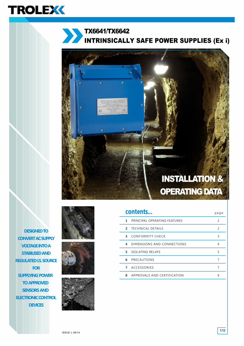
TX6641/TX6642 INTRINSICALLY SAFE POWER SUPPLIES (Ex i)
12
1/12 INSTALLATION & OPERATING DATA contents... page 1 PRINCIPAL OPERATING FEATURES 2 2 TECHNICAL DETAILS 2 3 CONFORMITY CHECK 3 4 DIMENSIONS AND CONNECTIONS 4 5 ISOLATING RELAYS 5 6 PRECAUTIONS 7 7 ACCESSORIES 7 8 APPROVALS AND CERTIFICATION 9 DESIGNEDTO CONVERTACSUPPLY VOLTAGE INTOA STABILISEDAND REGULATED I.S. SOURCE FOR SUPPLYING POWER TO APPROVED SENSORS AND ELECTRONICCONTROL DEVICES T X X 9 9 1 1 3 3 0 0 s s e e r r i i e e s s TX6641/TX6642 INTRINSICALLY SAFE POWER SUPPLIES (Ex i) ISSUE L 06/14
Transcript of TX6641/TX6642 INTRINSICALLY SAFE POWER SUPPLIES (Ex i)
1/12
INSTALLATION &OPERATING DATA
contents... pag e
1 PRINCIPAL OPERATING FEATURES 2
2 TECHNICAL DETAILS 2
3 CONFORMITY CHECK 3
4 DIMENSIONS AND CONNECTIONS 4
5 ISOLATING RELAYS 5
6 PRECAUTIONS 7
7 ACCESSORIES 7
8 APPROVALS AND CERTIFICATION 9
DESIGNED TO
CONVERT AC SUPPLY
VOLTAGE INTO A
STABILISED AND
REGULATED I.S. SOURCE
FOR
SUPPLYING POWER
TO APPROVED
SENSORS AND
ELECTRONIC CONTROL
DEVICES
TT XX 99 11 33 00 ss ee rr ii ee ss
TX6641/TX6642INTRINSICALLY SAFE POWER SUPPLIES (Ex i)
ISSUE L 06/14

INSTALLATION & OPERATING DATA
The TX6641 Power Supply will convert an ac supply voltage into a stabilisedand regulated Intrinsically Safe source for supplying power to approvedsensors and electronic control devices.
Input voltage options: 110 V ac or 230 V ac
The input supply is protected by two primary fuses.
The output circuit is resistively limited in accordance withcertification standards for Intrinsically Safe, ia, equipment.
The TX6641 Power Supply Chassis may be fitted and wiredinto an existing Exd housing (specific systemcertification may also be required) or into a standardprotective housing that is in a SAFE AREA.
The TX6642 version is the TX6641Series Power supply mounted in aTrolex Exd housing for use in a
Group I hazardous area.
Intrinsically Safe isolation relays may be supplied with allversions for switching control currents emanating from
other Ex d enclosures or high voltage systems.
1 PRINCIPAL OPERATING FEATURES
2 TECHNICAL DETAILSInput Voltage: 110 V ac or 230 V ac, 50/60 Hz
Output Voltage: 12 V dc ±
Output Current: 900 mA
Output Ripple/Noise: 150 V max.
Line Regulation: <5% over the input voltage range.
Load Regulation: Better than 5% over 10% of load current (–10% at full load).
Voltage Limiting: Over voltage detection with fuse rupturing ‘crowbar’ protection and shortprotection.
Current Limiting: Automatic current limiting to the intrinsically safe output also limits the
current to less than the rupturing capacity of the output protection fuse.‘Reset’ the power supply by removing the output load and then reconnecting.
Max. Operating Temperature: –20°C to +40°C.
Storage Temperature: –20°C to +70°C.
Humidity: 0 to 95% RH, non-condensing.
Vibration Limits/Low Frequency: 0.25 mm pk, sinusoidal vibration in the range 10 Hz to 100 Hz in3 perpendicular planes.
Medium Frequency: 2 g pk, sinusoidal vibration in the range 10 Hz to 600 Hz in 3 perpendicular planes.
Mechanical Shock: 1000 shocks of 40 g minimum in 3 perpendicular planes.
CurrentLimit
Crowbar
PowerInput
ExiOutput
TT XX 99 11 33 00 ss ee rr ii ee ss
0.0 V0.6 V
2/12
I.S. FuseInput Fuse
ISSUE L 06/14

INSTALLATION & OPERATING DATA
Does the supply voltage marked on the product agree with the
locally available supply?
Check that the output current rating marked on
the product is adequate for the total current
demand of the system being installed.
Is the Power Supply mounted in the correct enclosure for the
application?
Ensure that the Power Supply certification details are fully compliant
with the monitoring system requirements.
If in any doubt, please contact the Trolex Sales department.
Is the output voltage correct for the system being used?
If isolating relays are fitted, is the voltage rating of the coils correct?
If isolating relays are fitted, are the relay parameters
suitable for the load being switched?
3 CONFORMITY CHECK
110 V ac 230 V ac
900 mA
Ex d or Safe Area
Ex i Group I
TX6641 INTRINSICALLY SAFE POWER SUPPLY CHASSIS(Supplied loose, ready for fitting and wiring)
TX6642 INTRINSICALLY SAFE POWER SUPPLYin Ex d Housing
OPTIONS AVAILABLE
Input Voltage Options:
110 V ac (.105)
230 V ac (.106)
Refer to Section 4.1
Refer to Sect ion 6
Refer to Sect ion 5
Refer to Sect ion 5
TT XX 99 11 33 00 ss ee rr ii ee ss
12 V dc
12 V dc
3/12ISSUE L 06/14

INSTALLATION & OPERATING DATA
ALL DIMENSIONS IN MM
4 DIMENSIONS
ALL DIMENSIONS IN MM
+V0V
110 V ac or 230 V acSupply
+V
12 V dcoutput
0V
+V0V
110 V ac or 230 V acSupply
310.0
50.0 210.0 Centres
320.
0
304.
0 C
en
tres
8.0
8 - 9.0Fixing Holes.
Earth Stud 5 - M25 ExdGland Entries.
Ex i Chamber
Ex d Chamber
38.0
304.
0 C
en
tres
122.02 - M20GlandEntries.
4 .1 TX6641 INTRINSICALLY SAFE POWER SUPPLY CHASSIS
4.2 TX6642 INTRINSICALLY SAFE POWER SUPPLY in Ex d HOUSING
4 Ø 6.0 Fixing Holes
165
140
12.5
30267215
93
Current Limiting:
Automatic current
limiting to the intrinsically
safe output also limits the
current to less than the
rupturing capacity of the
output protection fuse.
‘Reset’ the power supply
by removing the output
load and then
reconnecting.
Connections
Connections
TT XX 99 11 33 00 ss ee rr ii ee ss
4/12
12 V dcoutput
Ex dchamber
Ex ichamber
ISSUE L 06/14

INSTALLATION & OPERATING DATA
5 ISOLATING RELAYS
5.1 Technical Details
Isolating relays may be combined with a TX6641 Power Supply. The operating coils of the
relays are Intrinsically Safe and the contacts are clearance compatible for switching
non-intrinsically safe apparatus or devices in separate Ex d enclosures (eg. P130 pilot circuits).
TX6641Power Supply
TX6641.19
IsolatingRelay
Ex dEquipment (GEB)
Exi
P130
A standard power supply chassis is fitted
and wired with four independent relays
with field connection facilities for coils
and contacts.
TX6641.19
Quantity of Relays 4
Contact Type One changeover
Contact Rating 5 A, 230 V ac
Coil Resistance 460 Ohms
Coil Voltage 12 V dc
Current Consumption (each) 26 mA
ALL DIMENSIONS IN MM
R2
R2
R1
R1
R4
R3
Cable markersindicate relay number
+V0V
R4 R3
110 V ac or 230 V acSupply
2 a2 b2 c
1 a1 b1 c
3 a3 b3 c
4 a4 b4 c
Ex i
Chamber
R2
R1
R4
R3+V0V
2 a2 b2 c
1 a1 b1 c
3 a3 b3 c
4 a4 b4 c
+V +V +V +VR1 R2 R3 R4
310.0
50.0 210.0 Centres
320
.0
304.
0 C
entr
es
8.0
8 - 9.0Fixing Holes.
Earth Stud 5 - M25 ExdGland Entries.
Ex i Chamber
Ex d Chamber
38.0
304.
0 C
entr
es
122.02 - M20GlandEntries.
5.2 Dimensions
5.2 .1 TX6641.19 INTRINSICALLY SAFE POWER SUPPLY CHASSIS , with 4 ISOLATING RELAYS
5.2 .2 TX6642.19 INTRINSICALLY SAFE POWER SUPPLY in Ex d HOUSING, with 4 ISOLATING RELAYS
ALL DIMENSIONS IN MM
215 .0
140
.0
30.0
12.5
267.0 (Baseplate)
271
165
.0
90.0
Connections
Connections
TT XX 99 11 33 00 ss ee rr ii ee ss
5/12
12 V dcoutput
12 V dcoutput
Contacts shown with relays de-energised
Ex d
Chamber
110 V ac or 230 V dcSupply
ISSUE L 06/14

INSTALLATION & OPERATING DATA
5 ISOLATING RELAYS continued
TX6641.19 INTRINSICALLY SAFE POWER SUPPLY CHASSISwith 4 Isolating Relays
TX6642.19 INTRINSICALLY SAFE POWER SUPPLYin Ex d Housing with 4 Isolating Relays
5.2 .3 OPTIONS AVAILABLE
Input Voltage Options:
110 V ac (.105)
230 V dc (.106)
6 PRECAUTIONS
Ensure that all covers on Ex d housings and their fixing devices are properly secured in compliance withstatutory Ex d regulations before switching on the input supply.
Never remove the cover of an Ex d housing whilst the input supply is connected. Isolate elsewherebefore removing the cover in accordance with statutory regulations.
The housing of all power supplies must be securely earthed in compliance with statutory regulations.Carry out a current consumption audit to ensure that the maximum current loading of the powersupply is not exceeded.
Ensure that the installation of the power supply, particularly with regard to theconnecting cables, complies with the certification parameters (section 8).
Ex d housings must be inspected and maintained regularly in accordance with statutory regulations.
Use only the correct Trolex replacement fuses (section 7).Do not substitute any form of equivalent or linking device.
The TX6641 Ex i Power Supply must be mounted in an approved Ex d housing when located in ahazardous area.
All cables entering the Ex d housing must be terminated with suitable Ex d certified cable glands.
Refer to Sect ion 8
Refer to Sect ion 7
TT XX 99 11 33 00 ss ee rr ii ee ss
6/12ISSUE L 06/14

INSTALLATION & OPERATING DATA
7 ACCESSORIES
REPLACEMENT FUSES
F1 = 5.0 A (F) Type S#401.0070
F2 = 3.15 A (T) Type S#401.0062
F3 = 3.15 A (T) Type S#401.0062
TO REPLACE A FUSE
Release quarter-turn fasteners and remove label
Remove 4 M2.5 countersunk head screws to allow removal
of the top plate assembly.
Place the top plate assembly to one side taking care not to
strain the connecting wires to the printed circuit board.
All the fuses are now accessible.
F1
F3 F2
F2
F3
F1
TT XX 99 11 33 00 ss ee rr ii ee ss
7/12
1A versions
ISSUE L 06/14

INSTALLATION & OPERATING DATA
7 ACCESSORIES continued
To change a fuse, the fuse cover must be removed to gain
access to the fuse holder.
Remove the blown fuse and replace it with a good one.
Note: The transformer securing screw may have to be loosened
to enable F4 fuse cover to be removed.
Ensure that the transformer securing screw is re-tightened.
All fuse covers must be replaced.
Replace top head cover assembly and secure with the
4 M2.5 countersunk head screws.
Re-fit the label plate.
TT XX 99 11 33 00 ss ee rr ii ee ss
8/12ISSUE L 06/14

INSTALLATION & OPERATING DATA
8 APPROVALS AND CERTIFICATION
8 .1 .1
TT XX 99 11 33 00 ss ee rr ii ee ss
Europe (ATEX)
Ex Certificate number: SIRA 01ATEX2229XEx Certification code: I (M1) [Ex ia Ma] I (Ta = -20°C to +55°C)
Specific Conditions of Use:
1. The TX6641 Power Supply Chassis shall be housed in an enclosure in accordance with the following criteria:
1.1 Safe area applications: The enclosure shall have an ingress protection of atleast IP20 and the circuits of the TX6641 shall have infallible creepage andclearance distances to the enclosure walls, as defined by clause 6.3 ofEN 60079-11:2007.
1.2 Hazardous area applications: The enclosure shall be certified and suitable foruse in hazardous area application; the arrangement of the TX6641 with theenclosure shall be re-certified by a notified body.
2. The connections to the relay boards must both be configured as either Option 1 orOption 2. It is not permitted to mix the connection of these relays.
3. The wiring carrying non-hazardous area circuits to the relays must be routed to ensurethat they are segregated from hazardous area circuits, maintaining compliance withTable 5 of EN 60079-11:2007, namely 6 mm of clearance through air and/or 1 mmclearance through solid insulation.
General Conditions of Use:
1. Prior to installation, it is essential that user refers to the above certificate to ensure that the termination and cable parameters are fully complied with and are compatible with the
application. Copies of certificates are available from Trolex.
ATEX Directive (94/9/EC)EMC Directive (2004/108/EC)
9/12
8.1 TX6641
ISSUE L 06/14

INSTALLATION & OPERATING DATA
8 APPROVALS AND CERTIFICATION continued
TT XX 99 11 33 00 ss ee rr ii ee ss
10/12
International (IECEx)
Ex Certificate number: IECEx SIR 10.0107XEx Certification code: [Ex ia Ma] I (Ta = -20°C to +55°C)
Conditions of Certification:
1. The TX6641 Power Supply Chassis shall be housed in an enclosure in accordance with thefollowing criteria:
1.1 Safe area applications: The enclosure shall have an ingress protection of at leastIP20 and the circuits of the TX6641 shall have infallible creepage and clearancedistances to the enclosure walls, as defined by clause 6.3 of IEC 60079-11:2006.
1.2 Hazardous area applications: The enclosure shall be certified and suitable for usein hazardous area application; the arrangement of the TX6641 with the enclosureshall be re-certified by a notified body.
2. The connections to the relay boards must both be configured as either Option 1 or Option 2. It is not permitted to mix the connection of these relays.
3. The wiring carrying non-hazardous area circuits to the relays must be routed to ensure that they are segregated from hazardous area circuits, maintaining compliance with
Table 5 of IEC 60079-11:2006, namely 6 mm of clearance through air and/or 1 mmclearance through solid insulation.
General Conditions of Use:
1. Prior to installation, it is essential that user refers to the above certificate to ensure thatthe termination and cable parameters are fully complied with and are compatible withthe application. Copies of certificates are available from Trolex.
Russia (GOST-R)
Ex certificate number: POCC GB.ME92.B02881
General Conditions of Use:
1. Prior to installation, it is essential that user refers to the above certificate for any specialconditions for safe use. The user must ensure that the termination and cable parametersare fully complied with and are compatible with the application. Copies of certificatesare available from Trolex.
8 . 1 . 3
8.1 TX6641 continued8 . 1 . 2
ISSUE L 06/14

8.1 TX6641 continued
INSTALLATION & OPERATING DATA
TT XX 99 11 33 00 ss ee rr ii ee ss
11/12
8 APPROVALS AND CERTIFICATION continued
South Africa (MASC)
Ex certificate number: MASC M/11-313XEx Certification code: [Ex ia Ma] I (Ta = -20°C to +55°C)
Specific Conditions of Use:
1. The TX6641 Power Supply Chassis shall be housed in an enclosure in accordance withthe following criteria:
1.1 Safe area applications: The enclosure shall have an ingress protection of at least IP20 and the circuits of the TX6641 shall have infallible creepage and clearance distances to the enclosure walls, as defined by clause 6.3 of EN 60079-11:2007.
1.2 Hazardous area applications: The enclosure shall be certified and suitable for use in hazardous area application; the arrangement of the TX6641 with the enclosure shall be re-certified by a notified body.
2. The connections to the relay boards must both be configured as either Option 1 or Option 2. It is not permitted to mix the connection of these relays.
3. The wiring carrying non-hazardous area circuits to the relays must be routed to ensure that they are segregated from hazardous area circuits, maintaining compliance with Table 5 of EN 60079-11:2007, namely 6 mm of clearance through air and/or 1 mm clearance through solid insulation.
General Conditions of Use:
1. Prior to installation, it is essential that user refers to the above certificate to ensure that the termination and cable parameters are fully complied with and are compatible with the application. Copies of certificates are available from Trolex.
Australia (ANZEx)
Ex Certificate number: ANZEx 14.3006XEx Certification code: [Ex ia] I (Ta = -20°C to +55°C)
Conditions of Safe Use:
1. The TX6641 Power Supply Chassis shall be housed in a suitably certified Ex d enclosure when used in a hazardous area. When used in a non-hazardous area it must be housed inside an enclosure that affords a degree of protection of at least IP20.
2. The TX6641 circuits must have infallible creepage and clearance distances to the enclosure walls, as defined by clause 6.3 of IEC 60079-11.
3. The connections to the relay boards must both be configured as either to IS circuits or non-IS circuits. It is not permitted to mix the connection of IS and non-IS circuits to these relays.
4. The wiring carrying non-hazardous area circuits to the relays must be routed to ensure that they are segregated from hazardous area circuits, maintaining compliance with Table 5 of IEC 60079-11:2011, namely 6 mm of clearance through air and/or 1 mm clearance through solid insulation.
General Conditions of Use:
1. Prior to installation, it is essential that user refers to the above certificate to ensure that the termination and cable parameters are fully complied with and are compatible with the application. Copies of certificates are available from Trolex.
8 . 1 . 4
8 . 1 . 5
ISSUE L 06/14

INSTALLATION & OPERATING DATA
TT XX 99 11 33 00 ss ee rr ii ee ss
TROLEX LIMITEDNEWBY ROAD, HAZEL GROVE, STOCKPORT,
CHESHIRE SK7 5DY, UK+44 (0)161 483 1435
Europe (ATEX)
Ex Certificate number: SIRA 01ATEX1230Ex Certification code: I M2 (M1) EEx d [ia] I (Ta = -20°C to +55°C)
General Conditions of Use:
1. Prior to installation, it is essential that user refers to the above certificate to ensure thatthe termination and cable parameters are fully complied with and are compatible withthe application. Copies of certificates are available from Trolex.
Russia (GOST-R)
Ex Certificate number: POCC GB.ME92.B02881
General Conditions of Use:
1. Prior to installation, it is essential that user refers to the above certificate for any specialconditions for safe use. The user must ensure that the termination and cable parametersare fully complied with and are compatible with the application. Copies of certificatesare available from Trolex.
Australia (ANZEx)
Ex Certificate number: ANZEx 14.3001XEx Certification code: Ex d [ia] I Mb (Ta = -20°C to +55°C)
Conditions of Safe Use:
1. It is a condition of specific use that the flamepath dimensions will be maintained in accordance with dimensions detailed in drawing P5531.02.02.
2. The installation entry to the main compartment shall be via suitably Ex d certified cable gland components.
3. It is a condition of the certificate that all conditions listed in ANZEx 14.3006X shall be applied.
General Conditions of Use:
1. Prior to installation, it is essential that user refers to the above certificate for any special conditions for safe use. The user must ensure that the termination and cable parameters are fully complied with and are compatible with the application. Copies of certificates are available from Trolex.
8.2 TX66428 . 2 . 1
8 . 2 . 2
8 . 2 . 3
8 APPROVALS AND CERTIFICATION continued
12/12ISSUE L 06/14