TX 4000 Installation Manual - Dialogic | Cloud-Optimized … · 2005-04-15 · The CP features one...
46
100 Crossing Boulevard Framingham, MA 01702-5406 USA www.nmscommunications.com TX 4000 Installation Manual P/N 9000-62334-13
Transcript of TX 4000 Installation Manual - Dialogic | Cloud-Optimized … · 2005-04-15 · The CP features one...
100 Crossing BoulevardFramingham, MA 01702-5406 USA
www.nmscommunications.com
TX 4000 Installation Manual
P/N 9000-62334-13

TX 4000 Installation Manual
2 NMS Communications
No part of this document may be reproduced or transmitted in any form or by any means without prior written consent of NMS Communications Corporation.
© 2005 NMS Communications Corporation. All Rights Reserved.
Alliance Generation is a registered trademark of NMS Communications Corporation or its subsidiaries. NMS Communications, Natural MicroSystems, AG, CG, CX, QX, Convergence Generation, Natural Access, CT Access, Natural Call Control, Natural Media, NaturalFax, NaturalRecognition, NaturalText, Fusion, Open Telecommunications, Natural Platforms, NMS HearSay, AccessGate, MyCaller, and HMIC are trademarks or service marks of NMS Communications Corporation or its subsidiaries. Multi-Vendor Integration Protocol (MVIP) is a registered trademark of GO-MVIP, Inc. UNIX is a registered trademark in the United States and other countries, licensed exclusively through X/Open Company, Ltd. Windows NT, MS-DOS, MS Word, Windows 2000, and Windows are either registered trademarks or trademarks of Microsoft Corporation in the United States and/or other countries. Clarent and Clarent ThroughPacket are trademarks of Clarent Corporation. Sun, Sun Microsystems, Solaris, Netra, and the Sun logo are trademarks or registered trademarks of Sun Microsystems, Inc. in the United States and/or other countries. All SPARC trademarks are used under license and are trademarks or registered trademarks of SPARC International, Inc. in the United States and/or other countries. Products bearing SPARC trademarks are based upon an architecture developed by Sun Microsystems, Inc. Linux is a registered trademark of Linus Torvalds. Red Hat is a registered trademark of Red Hat, Inc. All other marks referenced herein are trademarks or service marks of the respective owner(s) of such marks. All other products used as components within this product are the trademarks, service marks, registered trademarks, or registered service marks of their respective owners.
Every effort has been made to ensure the accuracy of this manual. However, due to the ongoing improvements and revisions to our products, NMS Communications cannot guarantee the accuracy of the printed material after the date of publication or accept responsibility for errors or omissions. Revised manuals and update sheets may be published when deemed necessary by NMS Communications.
P/N 9000-62334-13
Revision history
Revision Release date Notes
1.0 November 2003 SRR, SS7 4.0 Beta
1.1 April 2004 SRR, SS7 4.0
1.2 August 2004 SRR, SS7 4.1
1.3 April 2005 LBG, SS7 4.2
Last modified: April 15, 2005
Refer to www.nmscommunications.com for product updates and for information about NMS support policies, warranty information, and service offerings.
NMS Communications 3
Table Of Contents
Chapter 1: Introduction .................................................................................5
Chapter 2: Overview of the TX 4000 board ....................................................7 TX 4000 board features................................................................................ 7 Software components .................................................................................. 9 Utilities and demonstration programs ............................................................10
Chapter 3: Installing the TX 4000 board ......................................................13 System requirements..................................................................................13 Installation summary ..................................................................................14 Configuring the hardware ............................................................................15
Configuring H.100 bus termination.............................................................15 Configuring SS7 Monitor mode ..................................................................16 Diagnosing and recovering from hardware error conditions ............................16
Installing the board ....................................................................................17
Chapter 4: Configuring the TX 4000 board...................................................19 Using the configuration utility.......................................................................19 Assigning a CP number ...............................................................................20 Adding a board ..........................................................................................21 Changing a CP number................................................................................22 Moving a board ..........................................................................................23 Removing a board ......................................................................................24 Saving configuration changes.......................................................................25
Chapter 5: Establishing network connections ..............................................27 Connectors and cables ................................................................................27
T1/E1 jacks ............................................................................................27 Ethernet connectors.................................................................................29
Connecting to a T1 network .........................................................................30 Connecting to an E1 network .......................................................................31 Testing in loopback mode ............................................................................32 Connecting TX boards for redundancy ...........................................................33
Chapter 6: Verifying the installation ............................................................35 External connection status LEDs ...................................................................35 Ethernet LEDs............................................................................................36 Board status LEDs ......................................................................................37
Boot code LEDS.......................................................................................37 Status LEDs............................................................................................38
Verifying the board installation.....................................................................39
Chapter 7: Hardware specifications .............................................................41 General features ........................................................................................41 Host interface ............................................................................................41 H.100 compliant interface............................................................................41 Environment..............................................................................................42 Software environment.................................................................................42 Power requirements....................................................................................42 Connectivity ..............................................................................................42

Table of Contents TX 4000 Installation Manual
4 NMS Communications
CEPT E1 G.703 telephony interface ...............................................................42 DSX-1 telephony interface ...........................................................................43 Compliance and regulatory certification .........................................................44
EMC ......................................................................................................44 Safety....................................................................................................44 Telecom .................................................................................................44
NMS Communications 5
11 Introduction The TX 4000 Installation Manual explains how to perform the following tasks:
• Install the TX 4000 board
• Configure the TX 4000 board
• Establish network connections
• Verify the installation
This manual targets developers of telephony and voice applications who use TX 4000 boards with NMS SS7 software. This manual defines telephony terms where applicable, but assumes that the reader is familiar with telephony concepts, switching, and the C programming language.

NMS Communications 7
22 Overview of the TX 4000 board
TX 4000 board features
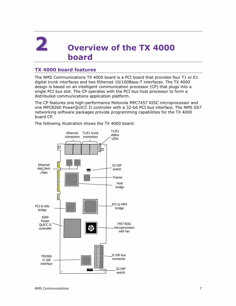
The NMS Communications TX 4000 board is a PCI board that provides four T1 or E1 digital trunk interfaces and two Ethernet 10/100Base-T interfaces. The TX 4000 design is based on an intelligent communication processor (CP) that plugs into a single PCI bus slot. The CP operates with the PCI bus host processor to form a distributed communications application platform.
The CP features one high-performance Motorola MPC7457 RISC microprocessor and one MPC8260 PowerQUICC II controller with a 32-bit PCI bus interface. The NMS SS7 networking software packages provide programming capabilities for the TX 4000 board CP.
The following illustration shows the TX 4000 board:
T1/E1 trunkconnectors
Ethernetconnectors
T1/E1statusLEDs
EthernetMAC/PHY
chips
Framer
Hostbridge
PCI to MPXbridge
7457 RISCmicroprocessor
with fan
H.100 busconnector
T8100AH.100
interface
PCI to 60xbridge
8260Power
QUICC IIcontroller
S2 DIPswitch
S3 DIPswitch
Overview of the TX 4000 board TX 4000 Installation Manual
8 NMS Communications
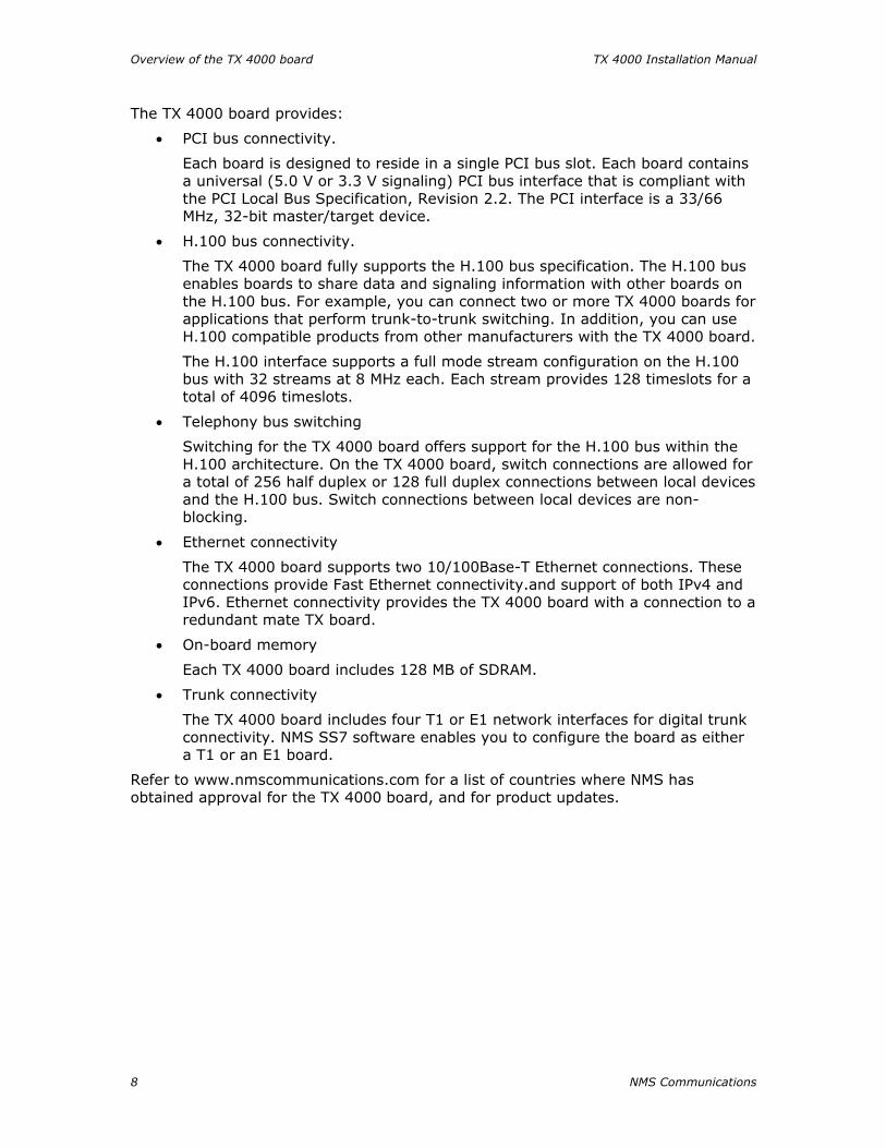
The TX 4000 board provides:
• PCI bus connectivity.
Each board is designed to reside in a single PCI bus slot. Each board contains a universal (5.0 V or 3.3 V signaling) PCI bus interface that is compliant with the PCI Local Bus Specification, Revision 2.2. The PCI interface is a 33/66 MHz, 32-bit master/target device.
• H.100 bus connectivity.
The TX 4000 board fully supports the H.100 bus specification. The H.100 bus enables boards to share data and signaling information with other boards on the H.100 bus. For example, you can connect two or more TX 4000 boards for applications that perform trunk-to-trunk switching. In addition, you can use H.100 compatible products from other manufacturers with the TX 4000 board.
The H.100 interface supports a full mode stream configuration on the H.100 bus with 32 streams at 8 MHz each. Each stream provides 128 timeslots for a total of 4096 timeslots.
• Telephony bus switching
Switching for the TX 4000 board offers support for the H.100 bus within the H.100 architecture. On the TX 4000 board, switch connections are allowed for a total of 256 half duplex or 128 full duplex connections between local devices and the H.100 bus. Switch connections between local devices are non-blocking.
• Ethernet connectivity
The TX 4000 board supports two 10/100Base-T Ethernet connections. These connections provide Fast Ethernet connectivity.and support of both IPv4 and IPv6. Ethernet connectivity provides the TX 4000 board with a connection to a redundant mate TX board.
• On-board memory
Each TX 4000 board includes 128 MB of SDRAM.
• Trunk connectivity
The TX 4000 board includes four T1 or E1 network interfaces for digital trunk connectivity. NMS SS7 software enables you to configure the board as either a T1 or an E1 board.
Refer to www.nmscommunications.com for a list of countries where NMS has obtained approval for the TX 4000 board, and for product updates.

TX 4000 Installation Manual Overview of the TX 4000 board
NMS Communications 9
Software components
TX 4000 boards require the following software components:
• Natural Access software development environment that provides services for call control, system configuration, voice store and forward, and other functions. Each service has a standard programming interface for developing applications. Refer to the Natural Access Developer's Reference Manual for more information.
• NMS SS7 software that provides SS7 protocol layer executables and program interfaces for developing signaling and management applications. It also provides utilities that download configuration information to the TX boards and that control, monitor, and collect statistics on the SS7 protocol layer. Refer to the NMS SS7 Configuration Manual for more information.
Overview of the TX 4000 board TX 4000 Installation Manual
10 NMS Communications
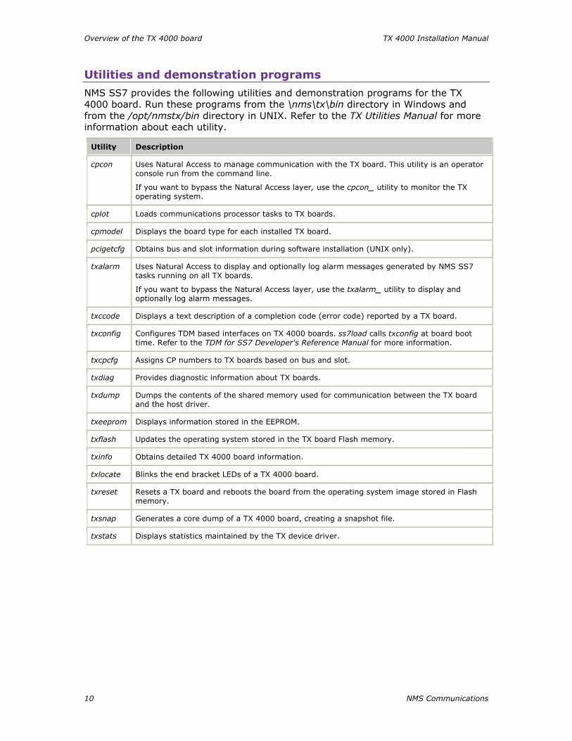
Utilities and demonstration programs
NMS SS7 provides the following utilities and demonstration programs for the TX 4000 board. Run these programs from the \nms\tx\bin directory in Windows and from the /opt/nmstx/bin directory in UNIX. Refer to the TX Utilities Manual for more information about each utility.
Utility Description
cpcon Uses Natural Access to manage communication with the TX board. This utility is an operator console run from the command line.
If you want to bypass the Natural Access layer, use the cpcon_ utility to monitor the TX operating system.
cplot Loads communications processor tasks to TX boards.
cpmodel Displays the board type for each installed TX board.
pcigetcfg Obtains bus and slot information during software installation (UNIX only).
txalarm Uses Natural Access to display and optionally log alarm messages generated by NMS SS7 tasks running on all TX boards.
If you want to bypass the Natural Access layer, use the txalarm_ utility to display and optionally log alarm messages.
txccode Displays a text description of a completion code (error code) reported by a TX board.
txconfig Configures TDM based interfaces on TX 4000 boards. ss7load calls txconfig at board boot time. Refer to the TDM for SS7 Developer's Reference Manual for more information.
txcpcfg Assigns CP numbers to TX boards based on bus and slot.
txdiag Provides diagnostic information about TX boards.
txdump Dumps the contents of the shared memory used for communication between the TX board and the host driver.
txeeprom Displays information stored in the EEPROM.
txflash Updates the operating system stored in the TX board Flash memory.
txinfo Obtains detailed TX 4000 board information.
txlocate Blinks the end bracket LEDs of a TX 4000 board.
txreset Resets a TX board and reboots the board from the operating system image stored in Flash memory.
txsnap Generates a core dump of a TX 4000 board, creating a snapshot file.
txstats Displays statistics maintained by the TX device driver.

TX 4000 Installation Manual Overview of the TX 4000 board
NMS Communications 11
NMS SS7 provides the following programs in compiled and uncompiled form to demonstrate the usage of the TDM libraries. Refer to the TDM for SS7 Developer's Reference Manual for information about these programs.
Program Demonstrates how to...
t1demo Test the T1/E1 and H.100 library functions with TX boards in a system.
t1stat Receive unsolicited T1/E1 status messages and performance reports.
txdynamic Dynamically switch SS7 links across TDM channels without rebooting the TX boards.
txsdemo Use the TX SWI library. Use this program as a starting point to control switching on a TX 4000 board.

NMS Communications 13
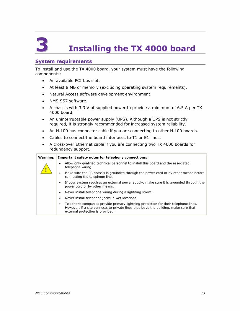
33 Installing the TX 4000 board System requirements
To install and use the TX 4000 board, your system must have the following components:
• An available PCI bus slot.
• At least 8 MB of memory (excluding operating system requirements).
• Natural Access software development environment.
• NMS SS7 software.
• A chassis with 3.3 V of supplied power to provide a minimum of 6.5 A per TX 4000 board.
• An uninterruptable power supply (UPS). Although a UPS is not strictly required, it is strongly recommended for increased system reliability.
• An H.100 bus connector cable if you are connecting to other H.100 boards.
• Cables to connect the board interfaces to T1 or E1 lines.
• A cross-over Ethernet cable if you are connecting two TX 4000 boards for redundancy support.
Warning:
Important safety notes for telephony connections:
• Allow only qualified technical personnel to install this board and the associated telephone wiring.
• Make sure the PC chassis is grounded through the power cord or by other means before connecting the telephone line.
• If your system requires an external power supply, make sure it is grounded through the power cord or by other means.
• Never install telephone wiring during a lightning storm.
• Never install telephone jacks in wet locations.
• Telephone companies provide primary lightning protection for their telephone lines. However, if a site connects to private lines that leave the building, make sure that external protection is provided.
Installing the TX 4000 board TX 4000 Installation Manual
14 NMS Communications
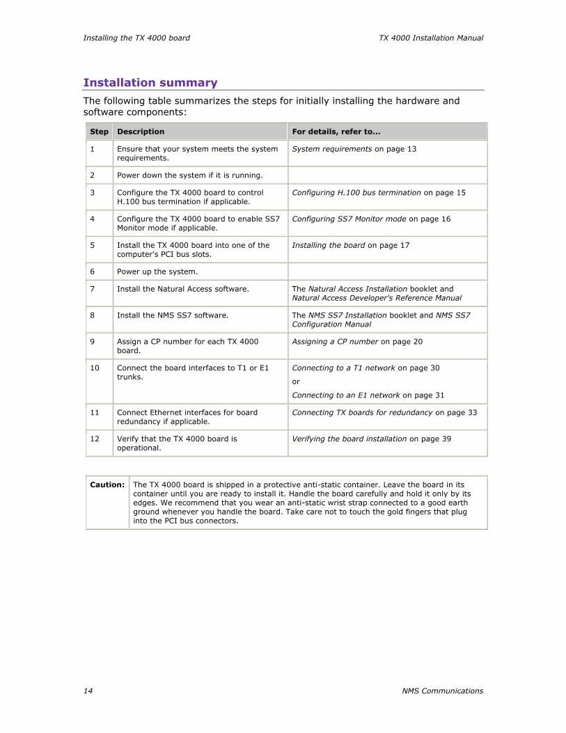
Installation summary
The following table summarizes the steps for initially installing the hardware and software components:
Step Description For details, refer to...
1 Ensure that your system meets the system requirements.
System requirements on page 13
2 Power down the system if it is running.
3 Configure the TX 4000 board to control H.100 bus termination if applicable.
Configuring H.100 bus termination on page 15
4 Configure the TX 4000 board to enable SS7 Monitor mode if applicable.
Configuring SS7 Monitor mode on page 16
5 Install the TX 4000 board into one of the computer's PCI bus slots.
Installing the board on page 17
6 Power up the system.
7 Install the Natural Access software. The Natural Access Installation booklet and Natural Access Developer's Reference Manual
8 Install the NMS SS7 software. The NMS SS7 Installation booklet and NMS SS7 Configuration Manual
9 Assign a CP number for each TX 4000 board.
Assigning a CP number on page 20
10 Connect the board interfaces to T1 or E1 trunks.
Connecting to a T1 network on page 30
or
Connecting to an E1 network on page 31
11 Connect Ethernet interfaces for board redundancy if applicable.
Connecting TX boards for redundancy on page 33
12 Verify that the TX 4000 board is operational.
Verifying the board installation on page 39
Caution: The TX 4000 board is shipped in a protective anti-static container. Leave the board in its container until you are ready to install it. Handle the board carefully and hold it only by its edges. We recommend that you wear an anti-static wrist strap connected to a good earth ground whenever you handle the board. Take care not to touch the gold fingers that plug into the PCI bus connectors.
TX 4000 Installation Manual Installing the TX 4000 board
NMS Communications 15
Configuring the hardware
This topic describes the following procedures for configuring the TX 4000 board:
• Configuring H.100 bus termination
• Configuring SS7 Monitor mode
• Diagnosing and recovering from hardware error conditions
Configuring H.100 bus termination
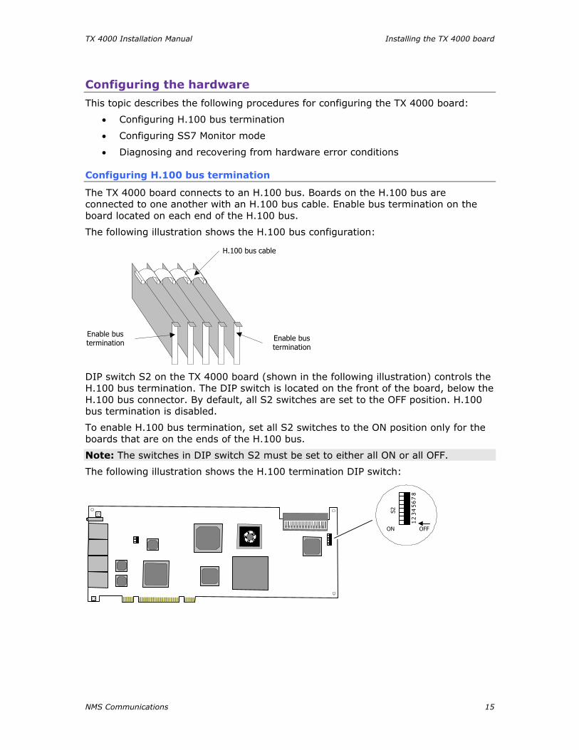
The TX 4000 board connects to an H.100 bus. Boards on the H.100 bus are connected to one another with an H.100 bus cable. Enable bus termination on the board located on each end of the H.100 bus.
The following illustration shows the H.100 bus configuration:
Enable bustermination
H.100 bus cable
Enable bustermination
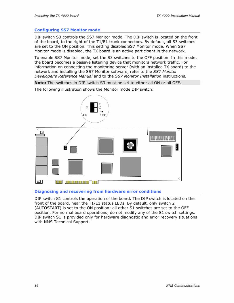
DIP switch S2 on the TX 4000 board (shown in the following illustration) controls the H.100 bus termination. The DIP switch is located on the front of the board, below the H.100 bus connector. By default, all S2 switches are set to the OFF position. H.100 bus termination is disabled.
To enable H.100 bus termination, set all S2 switches to the ON position only for the boards that are on the ends of the H.100 bus.
Note: The switches in DIP switch S2 must be set to either all ON or all OFF.
The following illustration shows the H.100 termination DIP switch:
S2
OFFON
12
34
56
78
Installing the TX 4000 board TX 4000 Installation Manual
16 NMS Communications
Configuring SS7 Monitor mode
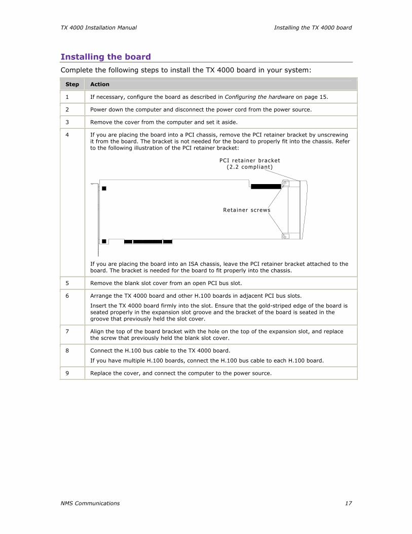
DIP switch S3 controls the SS7 Monitor mode. The DIP switch is located on the front of the board, to the right of the T1/E1 trunk connectors. By default, all S3 switches are set to the ON position. This setting disables SS7 Monitor mode. When SS7 Monitor mode is disabled, the TX board is an active participant in the network.
To enable SS7 Monitor mode, set the S3 switches to the OFF position. In this mode, the board becomes a passive listening device that monitors network traffic. For information on connecting the monitoring server (with an installed TX board) to the network and installing the SS7 Monitor software, refer to the SS7 Monitor Developer's Reference Manual and to the SS7 Monitor Installation instructions.
Note: The switches in DIP switch S3 must be set to either all ON or all OFF.
The following illustration shows the Monitor mode DIP switch:
S3
OFFON
12
34
Diagnosing and recovering from hardware error conditions
DIP switch S1 controls the operation of the board. The DIP switch is located on the front of the board, near the T1/E1 status LEDs. By default, only switch 2 (AUTOSTART) is set to the ON position; all other S1 switches are set to the OFF position. For normal board operations, do not modify any of the S1 switch settings. DIP switch S1 is provided only for hardware diagnostic and error recovery situations with NMS Technical Support.
TX 4000 Installation Manual Installing the TX 4000 board
NMS Communications 17
Installing the board
Complete the following steps to install the TX 4000 board in your system:
Step Action
1 If necessary, configure the board as described in Configuring the hardware on page 15.
2 Power down the computer and disconnect the power cord from the power source.
3 Remove the cover from the computer and set it aside.
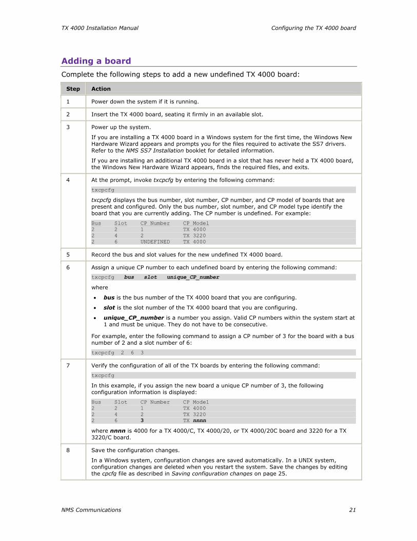
4 If you are placing the board into a PCI chassis, remove the PCI retainer bracket by unscrewing it from the board. The bracket is not needed for the board to properly fit into the chassis. Refer to the following illustration of the PCI retainer bracket:
PCI re ta iner b racke t(2 .2 comp l i an t )
Re ta ine r s c rews
If you are placing the board into an ISA chassis, leave the PCI retainer bracket attached to the board. The bracket is needed for the board to fit properly into the chassis.
5 Remove the blank slot cover from an open PCI bus slot.
6 Arrange the TX 4000 board and other H.100 boards in adjacent PCI bus slots.
Insert the TX 4000 board firmly into the slot. Ensure that the gold-striped edge of the board is seated properly in the expansion slot groove and the bracket of the board is seated in the groove that previously held the slot cover.
7 Align the top of the board bracket with the hole on the top of the expansion slot, and replace the screw that previously held the blank slot cover.
8 Connect the H.100 bus cable to the TX 4000 board.
If you have multiple H.100 boards, connect the H.100 bus cable to each H.100 board.
9 Replace the cover, and connect the computer to the power source.


NMS Communications 19
44 Configuring the TX 4000 board Using the configuration utility
After initially installing the TX 4000 board and the NMS SS7 software as outlined in the installation summary on page 14, you must assign a CP number to each TX 4000 board by using the txcpcfg utility. Depending on the operating environment, the txcpcfg utility is located in the following directory:
Operating system Directory
Windows \nms\tx\bin\
UNIX /opt/nmstx/bin/
txcpcfg enables you to make the following types of changes to the configuration information:
• Assign a CP number
• Add a board
• Change a CP number
• Move a board
• Remove a board
• Save configuration changes
For more information about txcpcfg, refer to the TX Utilities Manual.

Configuring the TX 4000 board TX 4000 Installation Manual
20 NMS Communications
Assigning a CP number
Complete the following steps to assign a CP number to an installed TX board:
Step Action
1 Power up the system if it is not running.
In a Windows system, the Windows New Hardware Wizard appears and prompts you for the files required to activate the SS7 drivers. Refer to the NMS SS7 Installation booklet for detailed information.
2 At the prompt, invoke txcpcfg by entering the following command:
txcpcfg
txcpcfg displays the bus number, slot number, CP number, and CP model of boards that are present and configured. Only the bus number, slot number, and CP model type identify the board that you are currently configuring. The CP number is undefined. For example:
Bus Slot CP Number CP Model 2 2 1 TX 4000 2 4 2 TX 3220 2 6 UNDEFINED TX 4000
3 Record the bus and slot values for the undefined TX 4000 board.
4 Assign a unique CP number to each undefined board by entering the following command:
txcpcfg bus slot unique_CP_number
where
• bus is the bus number of the TX 4000 board that you are configuring.
• slot is the slot number of the TX 4000 board that you are configuring.
• unique_CP_number is a number you assign. Valid CP numbers within the system start at 1 and must be unique. They do not have to be consecutive.
For example, enter the following command to assign a CP number of 3 for the board with a bus number of 2 and a slot number of 6:
txcpcfg 2 6 3
5 Verify the configuration of all of the TX boards by entering the following command:
txcpcfg
In this example if you assign the new board a unique CP number of 3, the following configuration information is displayed:
Bus Slot CP Number CP Model 2 2 1 TX 4000 2 4 2 TX 3220 2 6 3 TX nnnn where nnnn is 4000 for a TX 4000/C, TX 4000/20, or TX 4000/20C board and 3220 for a TX 3220/C board.
6 Save the configuration changes.
In a Windows system, configuration changes are saved automatically. In a UNIX system, configuration changes are deleted when you restart the system. Save the changes by editing the cpcfg file as described in Saving configuration changes on page 25.
TX 4000 Installation Manual Configuring the TX 4000 board
NMS Communications 21
Adding a board
Complete the following steps to add a new undefined TX 4000 board:
Step Action
1 Power down the system if it is running.
2 Insert the TX 4000 board, seating it firmly in an available slot.
3 Power up the system.
If you are installing a TX 4000 board in a Windows system for the first time, the Windows New Hardware Wizard appears and prompts you for the files required to activate the SS7 drivers. Refer to the NMS SS7 Installation booklet for detailed information.
If you are installing an additional TX 4000 board in a slot that has never held a TX 4000 board, the Windows New Hardware Wizard appears, finds the required files, and exits.
4 At the prompt, invoke txcpcfg by entering the following command:
txcpcfg
txcpcfg displays the bus number, slot number, CP number, and CP model of boards that are present and configured. Only the bus number, slot number, and CP model type identify the board that you are currently adding. The CP number is undefined. For example:
Bus Slot CP Number CP Model 2 2 1 TX 4000 2 4 2 TX 3220 2 6 UNDEFINED TX 4000
5 Record the bus and slot values for the new undefined TX 4000 board.
6 Assign a unique CP number to each undefined board by entering the following command:
txcpcfg bus slot unique_CP_number
where
• bus is the bus number of the TX 4000 board that you are configuring.
• slot is the slot number of the TX 4000 board that you are configuring.
• unique_CP_number is a number you assign. Valid CP numbers within the system start at 1 and must be unique. They do not have to be consecutive.
For example, enter the following command to assign a CP number of 3 for the board with a bus number of 2 and a slot number of 6:
txcpcfg 2 6 3
7 Verify the configuration of all of the TX boards by entering the following command:
txcpcfg
In this example, if you assign the new board a unique CP number of 3, the following configuration information is displayed:
Bus Slot CP Number CP Model 2 2 1 TX 4000 2 4 2 TX 3220 2 6 3 TX nnnn where nnnn is 4000 for a TX 4000/C, TX 4000/20, or TX 4000/20C board and 3220 for a TX 3220/C board.
8 Save the configuration changes.
In a Windows system, configuration changes are saved automatically. In a UNIX system, configuration changes are deleted when you restart the system. Save the changes by editing the cpcfg file as described in Saving configuration changes on page 25.
Configuring the TX 4000 board TX 4000 Installation Manual
22 NMS Communications
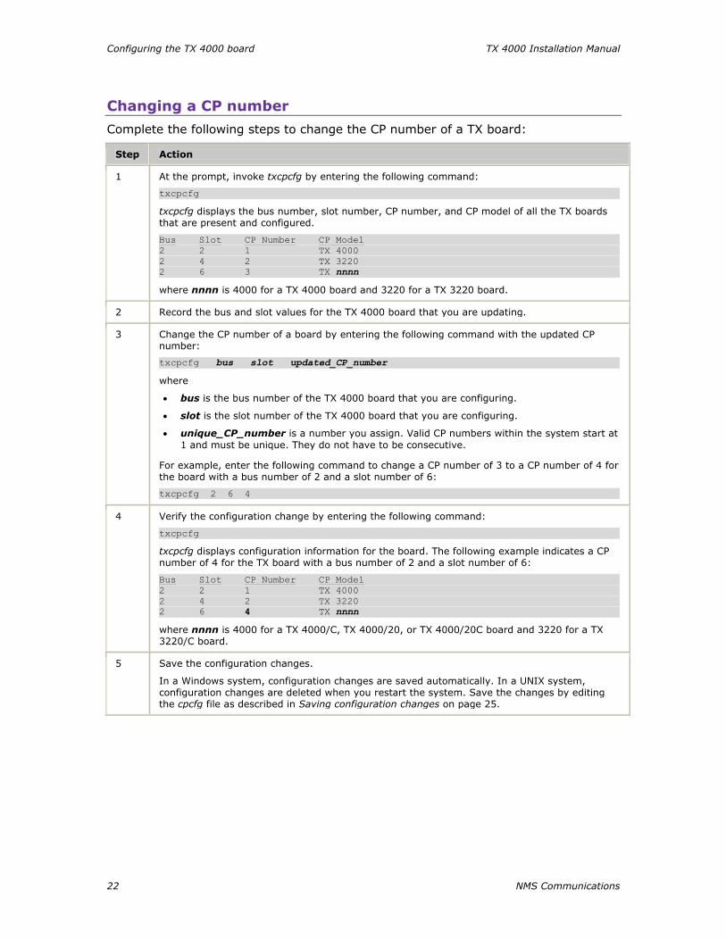
Changing a CP number
Complete the following steps to change the CP number of a TX board:
Step Action
1 At the prompt, invoke txcpcfg by entering the following command:
txcpcfg
txcpcfg displays the bus number, slot number, CP number, and CP model of all the TX boards that are present and configured.
Bus Slot CP Number CP Model 2 2 1 TX 4000 2 4 2 TX 3220 2 6 3 TX nnnn where nnnn is 4000 for a TX 4000 board and 3220 for a TX 3220 board.
2 Record the bus and slot values for the TX 4000 board that you are updating.
3 Change the CP number of a board by entering the following command with the updated CP number:
txcpcfg bus slot updated_CP_number
where
• bus is the bus number of the TX 4000 board that you are configuring.
• slot is the slot number of the TX 4000 board that you are configuring.
• unique_CP_number is a number you assign. Valid CP numbers within the system start at 1 and must be unique. They do not have to be consecutive.
For example, enter the following command to change a CP number of 3 to a CP number of 4 for the board with a bus number of 2 and a slot number of 6:
txcpcfg 2 6 4
4 Verify the configuration change by entering the following command:
txcpcfg
txcpcfg displays configuration information for the board. The following example indicates a CP number of 4 for the TX board with a bus number of 2 and a slot number of 6:
Bus Slot CP Number CP Model 2 2 1 TX 4000 2 4 2 TX 3220 2 6 4 TX nnnn where nnnn is 4000 for a TX 4000/C, TX 4000/20, or TX 4000/20C board and 3220 for a TX 3220/C board.
5 Save the configuration changes.
In a Windows system, configuration changes are saved automatically. In a UNIX system, configuration changes are deleted when you restart the system. Save the changes by editing the cpcfg file as described in Saving configuration changes on page 25.

TX 4000 Installation Manual Configuring the TX 4000 board
NMS Communications 23
Moving a board
Complete the following steps to move a TX board from one slot to another slot:
Step Action
1 Power down the system if it is running.
2 Move the TX 4000 board from one slot to another slot, seating it firmly in the new slot.
3 Power up the system.
In a Windows system: If you are installing a TX 4000 board in a slot that has never held a TX 4000 board, the Windows New Hardware Wizard appears, finds the required files, and exits.
4 At the prompt, invoke txcpcfg by entering the following command:
txcpcfg
txcpcfg displays the bus number, slot number, CP number, and CP model of boards that are present and configured. Only the bus number, slot number, and CP model type identify the board that you are currently configuring. The CP number is undefined. For example:
Bus Slot CP Number CP Model 2 2 1 TX 4000 2 4 2 TX 3220 2 8 UNDEFINED TX 4000
5 Record the bus and slot values for the TX 4000 board that you moved.
6 Assign a unique CP number to the undefined board by entering the following command:
txcpcfg bus slot unique_CP_number
where
• bus is the bus number of the TX 4000 board that you are configuring.
• slot is the slot number of the TX 4000 board that you are configuring.
• unique_CP_number is a number you assign. Valid CP numbers within the system start at 1 and must be unique. They do not have to be consecutive.
For example, enter the following command to assign a CP number of 3 for the board with a bus number of 2 and a slot number of 8:
txcpcfg 2 8 3
7 Verify the configuration change by entering the following command:
txcpcfg
txcpcfg displays configuration information. The following example indicates a CP number of 3 for the TX board with a bus number of 2 and a slot number of 8:
Bus Slot CP Number CP Model 2 2 1 TX 4000 2 4 2 TX 3220 2 8 3 TX nnnn where nnnn is 4000 for a TX 4000, TX 4000/20, TX 4000C, or TX 4000/20C board and 3220 for a TX 3220 or TX 3220C board.
8 Save the configuration changes.
In a Windows system, configuration changes are saved automatically. In a UNIX system, configuration changes are deleted when you restart the system. Save the changes by editing the cpcfg file as described in Saving configuration changes on page 25.
Configuring the TX 4000 board TX 4000 Installation Manual
24 NMS Communications
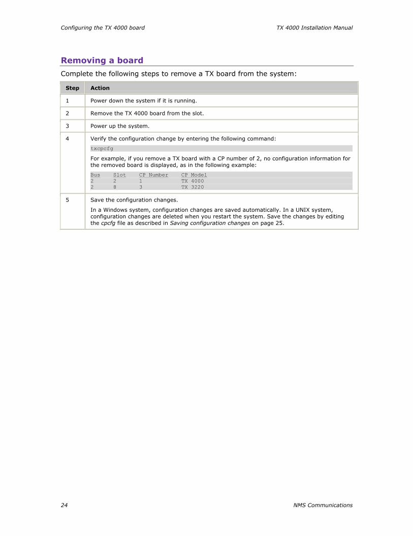
Removing a board
Complete the following steps to remove a TX board from the system:
Step Action
1 Power down the system if it is running.
2 Remove the TX 4000 board from the slot.
3 Power up the system.
4 Verify the configuration change by entering the following command:
txcpcfg
For example, if you remove a TX board with a CP number of 2, no configuration information for the removed board is displayed, as in the following example:
Bus Slot CP Number CP Model 2 2 1 TX 4000 2 8 3 TX 3220
5 Save the configuration changes.
In a Windows system, configuration changes are saved automatically. In a UNIX system, configuration changes are deleted when you restart the system. Save the changes by editing the cpcfg file as described in Saving configuration changes on page 25.
TX 4000 Installation Manual Configuring the TX 4000 board
NMS Communications 25
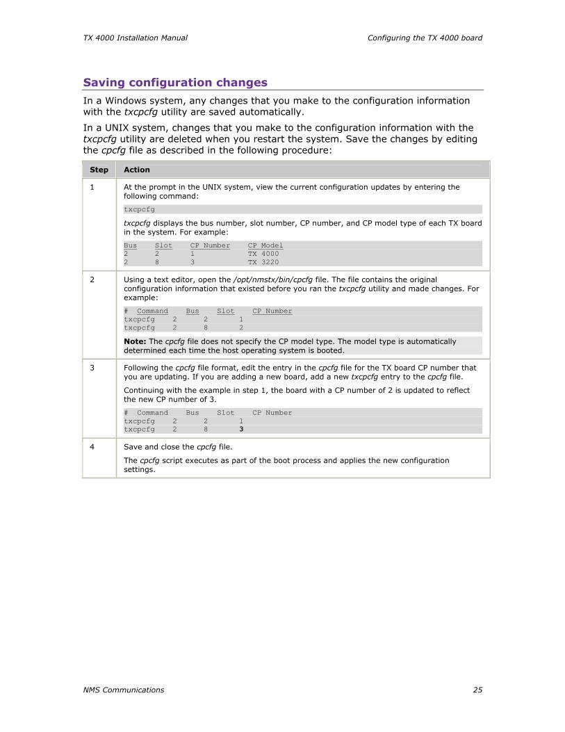
Saving configuration changes
In a Windows system, any changes that you make to the configuration information with the txcpcfg utility are saved automatically.
In a UNIX system, changes that you make to the configuration information with the txcpcfg utility are deleted when you restart the system. Save the changes by editing the cpcfg file as described in the following procedure:
Step Action
1 At the prompt in the UNIX system, view the current configuration updates by entering the following command:
txcpcfg
txcpcfg displays the bus number, slot number, CP number, and CP model type of each TX board in the system. For example:
Bus Slot CP Number CP Model 2 2 1 TX 4000 2 8 3 TX 3220
2 Using a text editor, open the /opt/nmstx/bin/cpcfg file. The file contains the original configuration information that existed before you ran the txcpcfg utility and made changes. For example:
# Command Bus Slot CP Number txcpcfg 2 2 1 txcpcfg 2 8 2
Note: The cpcfg file does not specify the CP model type. The model type is automatically determined each time the host operating system is booted.
3 Following the cpcfg file format, edit the entry in the cpcfg file for the TX board CP number that you are updating. If you are adding a new board, add a new txcpcfg entry to the cpcfg file.
Continuing with the example in step 1, the board with a CP number of 2 is updated to reflect the new CP number of 3.
# Command Bus Slot CP Number txcpcfg 2 2 1 txcpcfg 2 8 3
4 Save and close the cpcfg file.
The cpcfg script executes as part of the boot process and applies the new configuration settings.

NMS Communications 27
55 Establishing network connections
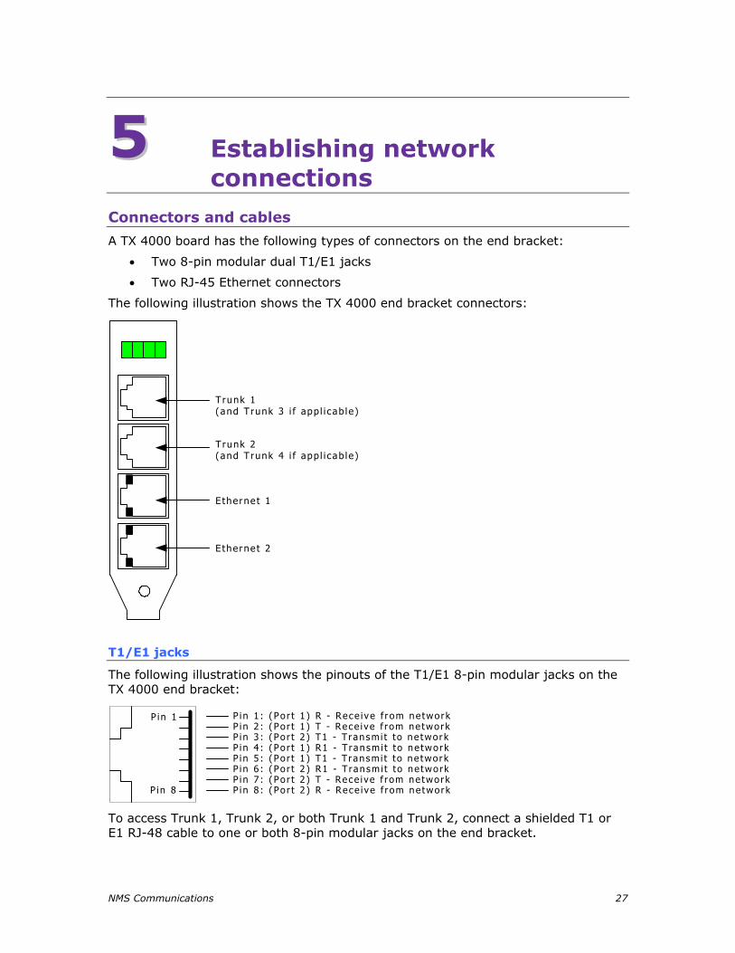
Connectors and cables
A TX 4000 board has the following types of connectors on the end bracket:
• Two 8-pin modular dual T1/E1 jacks
• Two RJ-45 Ethernet connectors
The following illustration shows the TX 4000 end bracket connectors:
Trunk 1(and Trunk 3 i f app l i cab le )
T runk 2(and Trunk 4 i f app l i cab le )
E therne t 1
E therne t 2
T1/E1 jacks
The following illustration shows the pinouts of the T1/E1 8-pin modular jacks on the TX 4000 end bracket:
P in 8 : (Po r t 2 ) R - Rece i ve f r om ne tworkP in 7 : (Po r t 2 ) T - Rece i ve f rom ne tworkP in 6 : (Po r t 2 ) R1 - T ransm i t to ne tworkP in 5 : (Po r t 1 ) T1 - T ransm i t to ne tworkP in 4 : (Po r t 1 ) R1 - T ransm i t to ne tworkP in 3 : (Po r t 2 ) T1 - T ransm i t to ne tworkP in 2 : (Po r t 1 ) T - Rece i ve f rom ne tworkP in 1 : (Po r t 1 ) R - Rece i ve f r om ne tworkP in 1
P in 8
To access Trunk 1, Trunk 2, or both Trunk 1 and Trunk 2, connect a shielded T1 or E1 RJ-48 cable to one or both 8-pin modular jacks on the end bracket.
Establishing network connections TX 4000 Installation Manual
28 NMS Communications
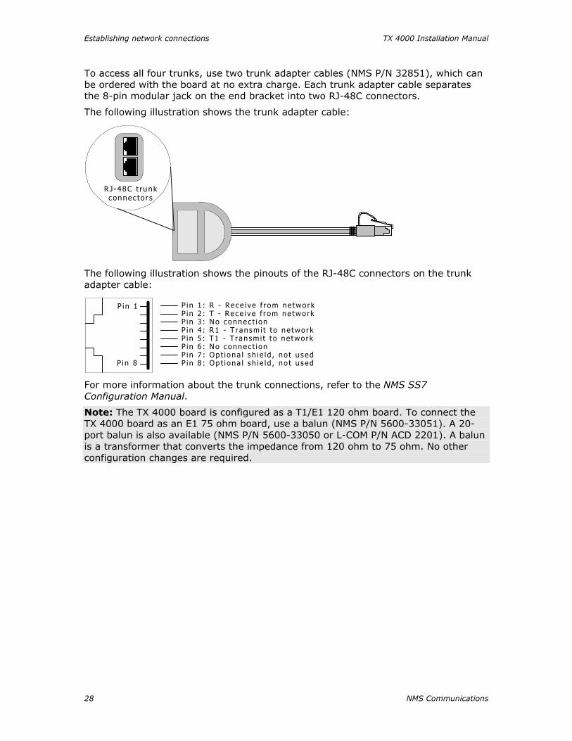
To access all four trunks, use two trunk adapter cables (NMS P/N 32851), which can be ordered with the board at no extra charge. Each trunk adapter cable separates the 8-pin modular jack on the end bracket into two RJ-48C connectors.
The following illustration shows the trunk adapter cable:
RJ-48C t runkconnec tor s
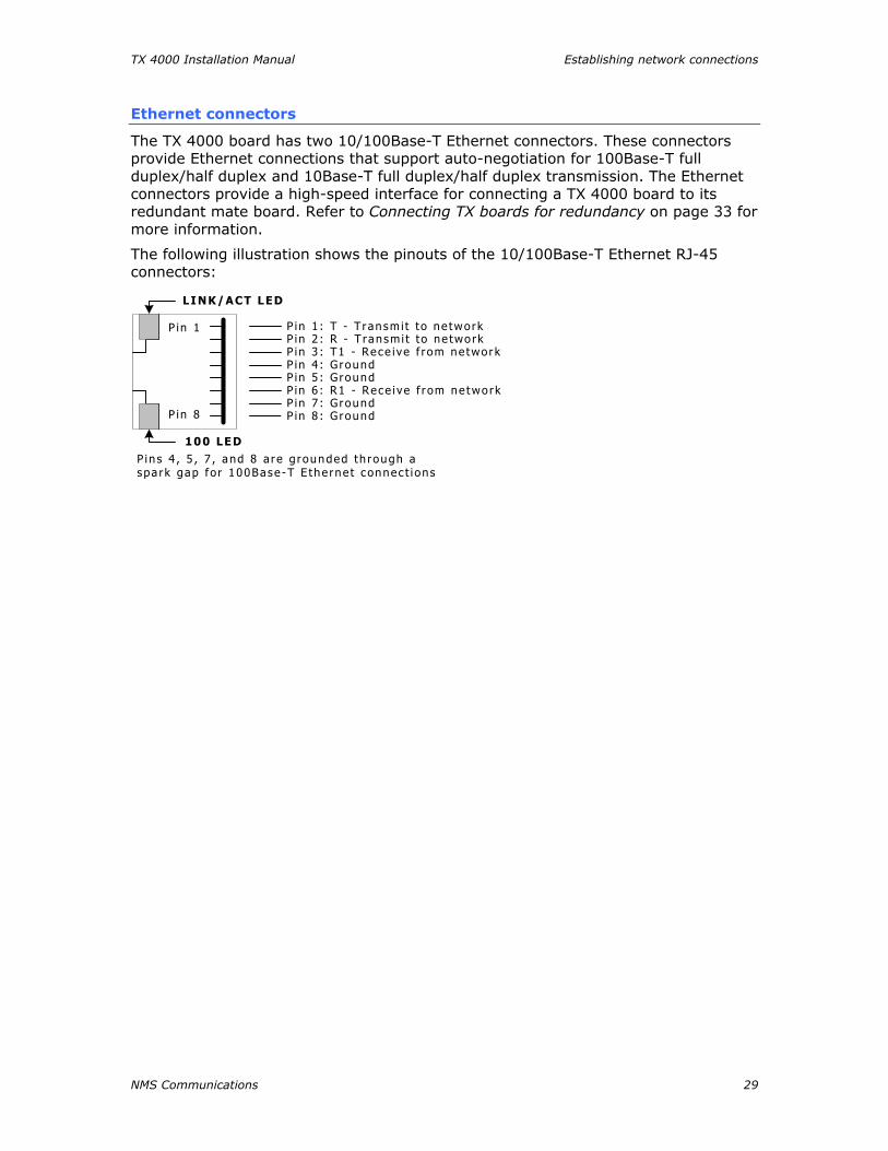
The following illustration shows the pinouts of the RJ-48C connectors on the trunk adapter cable:
P in 8 : Op t i ona l sh i e ld , no t u sedP in 7 : Op t i ona l sh i e ld , no t u sedP in 6 : No connec t i onP in 5 : T1 - T ransm i t t o ne tworkP in 4 : R1 - T ransm i t to ne tworkP in 3 : No connec t i onP in 2 : T - Rece i ve f r om ne tworkP in 1 : R - Rece i ve f rom ne tworkP in 1
P in 8
For more information about the trunk connections, refer to the NMS SS7 Configuration Manual.
Note: The TX 4000 board is configured as a T1/E1 120 ohm board. To connect the TX 4000 board as an E1 75 ohm board, use a balun (NMS P/N 5600-33051). A 20-port balun is also available (NMS P/N 5600-33050 or L-COM P/N ACD 2201). A balun is a transformer that converts the impedance from 120 ohm to 75 ohm. No other configuration changes are required.
TX 4000 Installation Manual Establishing network connections
NMS Communications 29
Ethernet connectors
The TX 4000 board has two 10/100Base-T Ethernet connectors. These connectors provide Ethernet connections that support auto-negotiation for 100Base-T full duplex/half duplex and 10Base-T full duplex/half duplex transmission. The Ethernet connectors provide a high-speed interface for connecting a TX 4000 board to its redundant mate board. Refer to Connecting TX boards for redundancy on page 33 for more information.
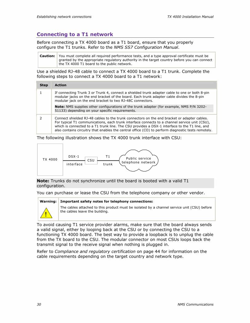
The following illustration shows the pinouts of the 10/100Base-T Ethernet RJ-45 connectors:
P in s 4 , 5 , 7 , and 8 a re g rounded th rough aspa rk gap f o r 100Base -T E the rne t connec t i ons
LINK/ACT LED
100 LED
P in 1
P in 8
P in 1 : T - T ransm i t to ne tworkP in 2 : R - T ransm i t to ne tworkP in 3 : T1 - Rece ive f rom ne tworkP in 4 : G roundP in 5 : G roundP in 6 : R1 - Rece i ve f r om ne tworkP in 7 : G roundP in 8 : G round
Establishing network connections TX 4000 Installation Manual
30 NMS Communications
Connecting to a T1 network
Before connecting a TX 4000 board as a T1 board, ensure that you properly configure the T1 trunks. Refer to the NMS SS7 Configuration Manual.
Caution: You must complete all required performance tests, and a type approval certificate must be granted by the appropriate regulatory authority in the target country before you can connect the TX 4000 T1 board to the public network.
Use a shielded RJ-48 cable to connect a TX 4000 board to a T1 trunk. Complete the following steps to connect a TX 4000 board to a T1 network:
Step Action
1 If connecting Trunk 3 or Trunk 4, connect a shielded trunk adapter cable to one or both 8-pin modular jacks on the end bracket of the board. Each trunk adapter cable divides the 8-pin modular jack on the end bracket to two RJ-48C connectors.
Note: NMS supplies other configurations of the trunk adapter (for example, NMS P/N 3202-51133) depending on your specific requirements.
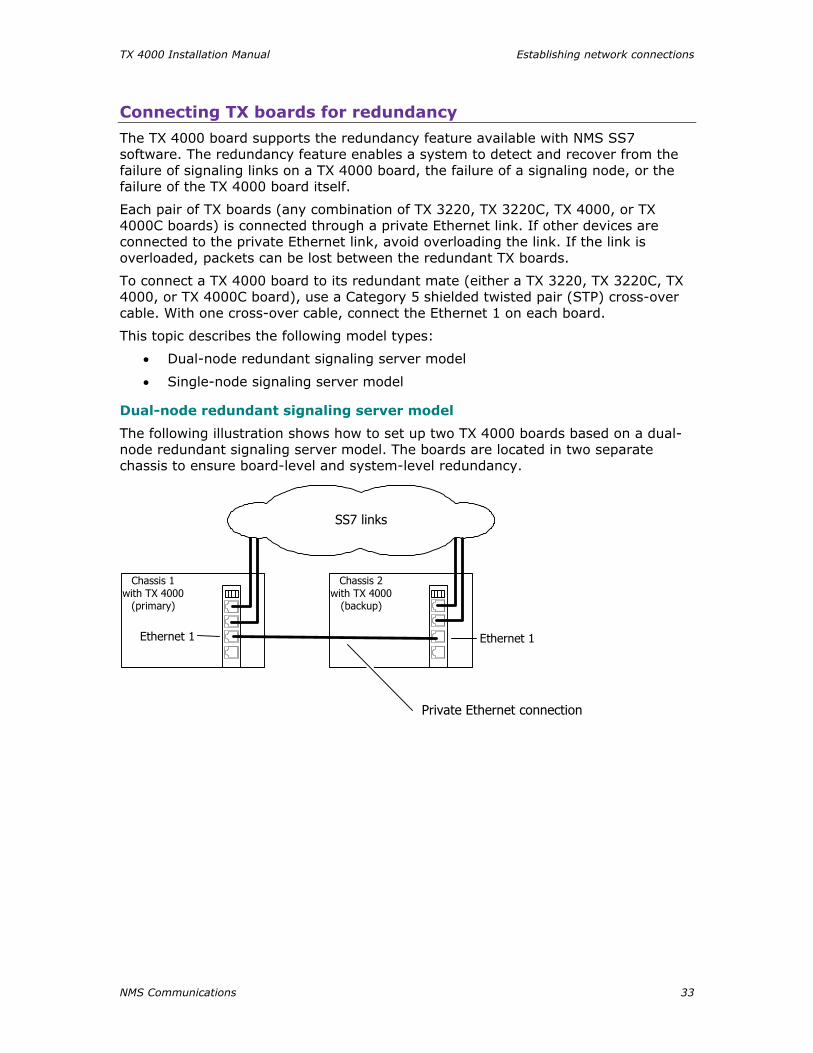
2 Connect shielded RJ-48 cables to the trunk connectors on the end bracket or adapter cables. For typical T1 communications, each trunk interface connects to a channel service unit (CSU), which is connected to a T1 trunk line. The CSU provides a DSX-1 interface to the T1 line, and also contains circuitry that enables the central office (CO) to perform diagnostic tests remotely.
The following illustration shows the TX 4000 trunk interface with CSU:
CSUDSX-1
i n te r f ace
T1
t runk
Pub l i c se rv i cete l ephone ne twork
TX 4000
Note: Trunks do not synchronize until the board is booted with a valid T1 configuration.
You can purchase or lease the CSU from the telephone company or other vendor.
Warning:
Important safety notes for telephony connections:
The cables attached to this product must be isolated by a channel service unit (CSU) before the cables leave the building.
To avoid causing T1 service provider alarms, make sure that the board always sends a valid signal, either by looping back at the CSU or by connecting the CSU to a functioning TX 4000 board. The best way to provide a loopback is to unplug the cable from the TX board to the CSU. The modular connector on most CSUs loops back the transmit signal to the receive signal when nothing is plugged in.
Refer to Compliance and regulatory certification on page 44 for information on the cable requirements depending on the target country and network type.

TX 4000 Installation Manual Establishing network connections
NMS Communications 31
Connecting to an E1 network
Before connecting a TX 4000 board as an E1 board, ensure that you have properly configured the E1 trunks. For configuration information, refer to the NMS SS7 Configuration Manual.
Caution: NMS Communications obtains board-level approval certificates for supported countries. Some countries require that you obtain system-level approvals for boards connected to the public network. To learn what approvals you require, contact the appropriate regulatory authority in the target country.
TX 4000 boards have as many as four CEPT E1 trunk interfaces. For typical E1 communications, each E1 interface connects directly to an E1 trunk, as shown in the following illustration:
E1 t runk
Pub l i c s e r v i cete l ephone ne twork
o r p ropr i e ta r yne twork
TX 4000
Note: Trunks do not synchronize until the board is booted with a valid E1 configuration.
Use a shielded RJ-48 cable to connect a TX 4000 board to an E1 120 ohm trunk. Complete the following steps to connect a TX 4000 board to an E1 network:
Step Action
1 If connecting Trunk 3 or Trunk 4, connect a shielded trunk adapter cable to one or both T1/E1 8-pin modular jacks on the end bracket of the board.
2
Connect shielded RJ-48 cables to the trunk connectors on the end bracket or adapter cables.
Caution: Failure to use a shielded cable may negate the Class B approval. Refer to Compliance and regulatory certification on page 44 for more information on class approvals.
The following illustration shows the trunk adapter cable:
RJ-48C t runkconnec tor s
Note: NMS supplies other configurations of the trunk adapter (for example, NMS P/N 3202-51133) depending on specialized requirements.

Establishing network connections TX 4000 Installation Manual
32 NMS Communications
Testing in loopback mode
You can connect the board in loopback mode to test the digital trunk application without connecting to the telephone network. The cross-over cable connects the transmit signals from one trunk to the receive signals on another trunk by connecting the pins as shown in the illustration. The following illustration shows the loopback configuration that connects trunk 1 and trunk 2 with cross-over cable (NMS P/N 31071) on a TX 4000 board:
1245
1245
Wi r ing d iag ram o f c ros s -ove r cab le
T runks1 and 3
Trunks2 and 4
Cross-over cablePN 31071
If your board configuration uses two optional trunk adapter cables (NMS P/N 32851) to access trunks 3 and 4, you can connect the adapter cables in loopback mode. Use the cross-over cable to connect the transmit signals on one of the adapter cables to the receive signals on the second adapter cable.
TX 4000 Installation Manual Establishing network connections
NMS Communications 33
Connecting TX boards for redundancy
The TX 4000 board supports the redundancy feature available with NMS SS7 software. The redundancy feature enables a system to detect and recover from the failure of signaling links on a TX 4000 board, the failure of a signaling node, or the failure of the TX 4000 board itself.
Each pair of TX boards (any combination of TX 3220, TX 3220C, TX 4000, or TX 4000C boards) is connected through a private Ethernet link. If other devices are connected to the private Ethernet link, avoid overloading the link. If the link is overloaded, packets can be lost between the redundant TX boards.
To connect a TX 4000 board to its redundant mate (either a TX 3220, TX 3220C, TX 4000, or TX 4000C board), use a Category 5 shielded twisted pair (STP) cross-over cable. With one cross-over cable, connect the Ethernet 1 on each board.
This topic describes the following model types:
• Dual-node redundant signaling server model
• Single-node signaling server model
Dual-node redundant signaling server model
The following illustration shows how to set up two TX 4000 boards based on a dual-node redundant signaling server model. The boards are located in two separate chassis to ensure board-level and system-level redundancy.
Chassis 1with TX 4000
(primary)
Chassis 2with TX 4000
(backup)
SS7 links
Private Ethernet connection
Ethernet 1Ethernet 1

Establishing network connections TX 4000 Installation Manual
34 NMS Communications
Single-node signaling server model
The following illustration shows how to set up two TX 4000 boards based on the single-node signaling server. The boards are located in the same chassis to ensure board-level redundancy.
SS7 links
TX 4000(Primary)
Chassis 1
Private Ethernet connection
Ethernet 1Ethernet 1
TX 4000(Backup)
For more information on SS7 redundancy, see the SS7 Health Management Developer's Reference Manual.
NMS Communications 35
66 Verifying the installation External connection status LEDs
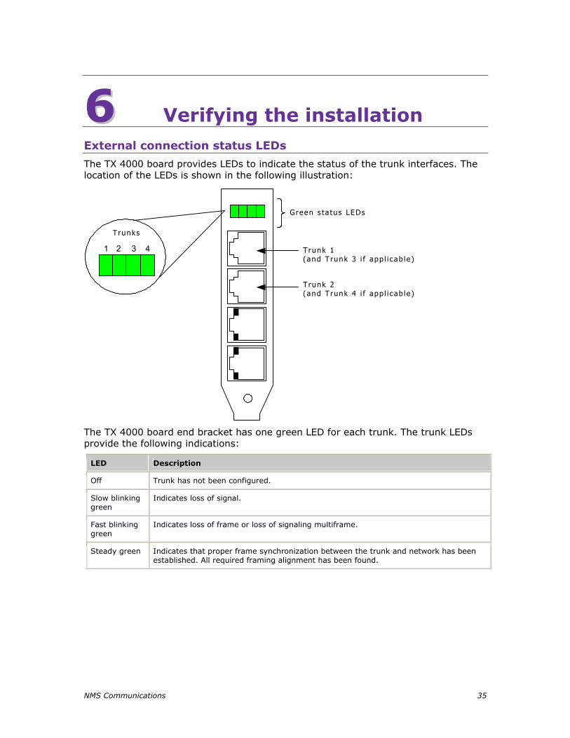
The TX 4000 board provides LEDs to indicate the status of the trunk interfaces. The location of the LEDs is shown in the following illustration:
Trunk 1(and Trunk 3 i f app l i cab le )
T runk 2(and Trunk 4 i f app l i cab le )
Green s ta tus LEDs
Trunks
1 432
The TX 4000 board end bracket has one green LED for each trunk. The trunk LEDs provide the following indications:
LED Description
Off Trunk has not been configured.
Slow blinking green
Indicates loss of signal.
Fast blinking green
Indicates loss of frame or loss of signaling multiframe.
Steady green Indicates that proper frame synchronization between the trunk and network has been established. All required framing alignment has been found.

Verifying the installation TX 4000 Installation Manual
36 NMS Communications
Ethernet LEDs
The TX 4000 board provides two LEDs to indicate the status of each Ethernet interface. The LEDs are located in the RJ-45 connectors as shown in the following illustration:
Etherne t 2 100 LED (green)
E therne t 2 L INK/ACT LED (g reen)
E the rne t 1 100 LED (green)
E therne t 1 L INK/ACT LED (green)
The following table describes the functionality of each LED:
LED Description
LINK/ACT Indicates the status of the Ethernet link. When the Ethernet link has established link integrity, the LED is on and steady. It also indicates the transmitting and receiving activity on the link. When activity is present on the Ethernet link, the LED flickers.
100 Indicates the data rate of the Ethernet link. When the LED is on, the data rate is 100 Mb. When the LED is off, the data rate is 10 Mb. The LED is used only when a reliable Ethernet connection has been established. (The LINK/ACT LED is on.)
TX 4000 Installation Manual Verifying the installation
NMS Communications 37
Board status LEDs
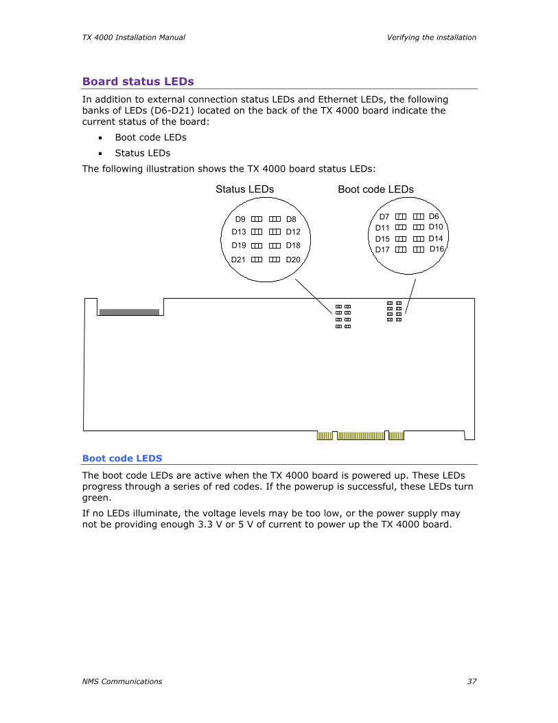
In addition to external connection status LEDs and Ethernet LEDs, the following banks of LEDs (D6-D21) located on the back of the TX 4000 board indicate the current status of the board:
• Boot code LEDs
• Status LEDs
The following illustration shows the TX 4000 board status LEDs:
D7D11D15D17
D6D10D14D16
Status LEDs Boot code LEDs
D9D13
D8
D18
D20
D19
D21
D12
Boot code LEDS
The boot code LEDs are active when the TX 4000 board is powered up. These LEDs progress through a series of red codes. If the powerup is successful, these LEDs turn green.
If no LEDs illuminate, the voltage levels may be too low, or the power supply may not be providing enough 3.3 V or 5 V of current to power up the TX 4000 board.

Verifying the installation TX 4000 Installation Manual
38 NMS Communications
Status LEDs
After the boot code LEDs become green, the status LEDs are active and indicate the current board status as described in the following table:
LED number Color Status when illuminated
D8 Green Timer interrupt controlled heartbeat. The LED flickers to show that the timer interrupts are operating properly.
D9 Green Idle task controlled heartbeat. The LED flickers to show that the on-board operating system is operational.
D12 Red The board is executing in snapshot mode: the board is resetting or txsnap is running.
D13 ------ Reserved for internal use.
D18 Red The kernel detected a host communication error.
D19 Red A memory full condition occurred on the board.
D20 Red An unexpected exception occurred on the board.
D21 Red The kernel detected a problem. Use the cpcon utility's log command to view logged error information. For information about using cpcon, refer to the TX Utilities Manual.
TX 4000 Installation Manual Verifying the installation
NMS Communications 39
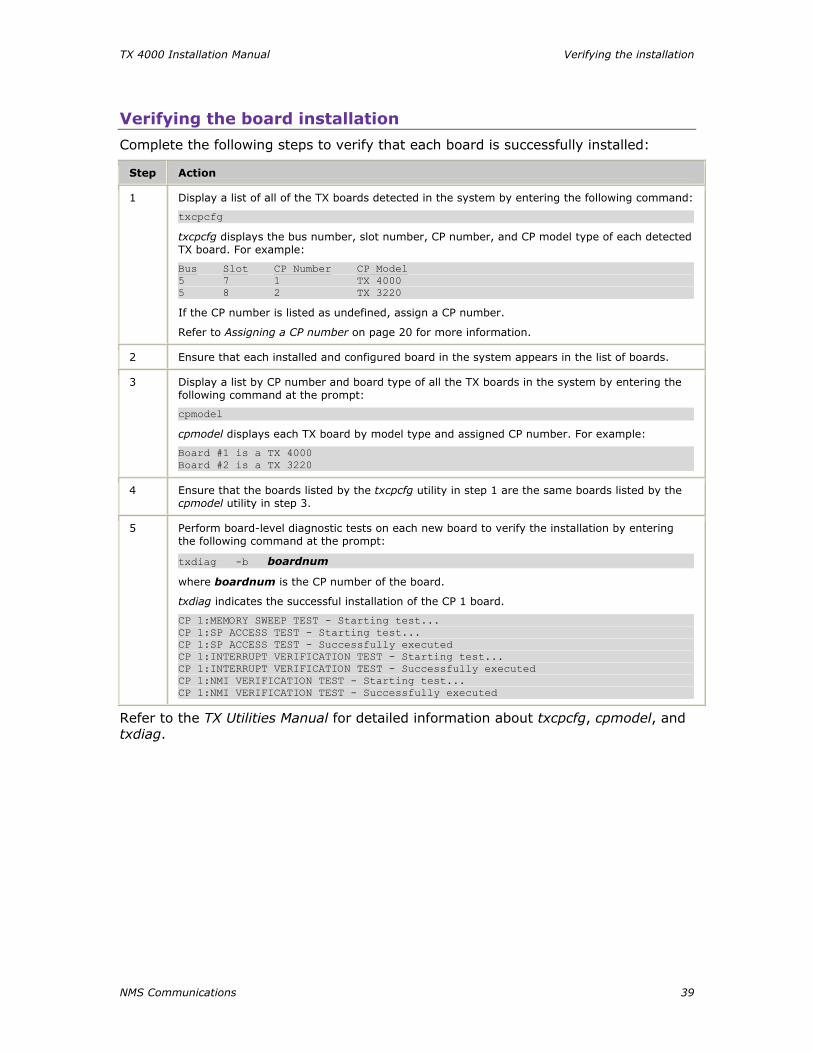
Verifying the board installation
Complete the following steps to verify that each board is successfully installed:
Step Action
1 Display a list of all of the TX boards detected in the system by entering the following command:
txcpcfg
txcpcfg displays the bus number, slot number, CP number, and CP model type of each detected TX board. For example:
Bus Slot CP Number CP Model 5 7 1 TX 4000 5 8 2 TX 3220
If the CP number is listed as undefined, assign a CP number.
Refer to Assigning a CP number on page 20 for more information.
2 Ensure that each installed and configured board in the system appears in the list of boards.
3 Display a list by CP number and board type of all the TX boards in the system by entering the following command at the prompt:
cpmodel
cpmodel displays each TX board by model type and assigned CP number. For example:
Board #1 is a TX 4000 Board #2 is a TX 3220
4 Ensure that the boards listed by the txcpcfg utility in step 1 are the same boards listed by the cpmodel utility in step 3.
5 Perform board-level diagnostic tests on each new board to verify the installation by entering the following command at the prompt:
txdiag -b boardnum
where boardnum is the CP number of the board.
txdiag indicates the successful installation of the CP 1 board.
CP 1:MEMORY SWEEP TEST - Starting test... CP 1:SP ACCESS TEST - Starting test... CP 1:SP ACCESS TEST - Successfully executed CP 1:INTERRUPT VERIFICATION TEST - Starting test... CP 1:INTERRUPT VERIFICATION TEST - Successfully executed CP 1:NMI VERIFICATION TEST - Starting test... CP 1:NMI VERIFICATION TEST - Successfully executed
Refer to the TX Utilities Manual for detailed information about txcpcfg, cpmodel, and txdiag.

NMS Communications 41
77 Hardware specifications General features
Feature Specification
Form factor Standard length PCI board
PCI bus 33/66 MHz, 32-bit master/target or slave 5.0 V or 3.3 V signaling compatible slot
Input/output PCI end bracket
Board weight 0.40 lb (0.20 kg)
Host interface
Feature Specification
Electrical PCI bus designed to PCI Local Bus Specification Revision 2.2
Mechanical Designed to PCI Local Bus Specification Revision 2.2
Bus speed DC to 66 MHz
Maximum number of boards per chassis 16
Maximum number of SS7 links per board 32 per TX 4000 board
16 per TX 4000/20 board
I/O mapped memory Memory mapped interface for efficient block data transfers
Plug and play Compatible (Windows only)
H.100 compliant interface
H.100 compliant interface has the following features:
• Flexible connectivity between T1 and E1 trunks and the H.100 bus
• Access to any of 4096 H.100 timeslots
• Compatible with any H.100 compliant telephony interface
• H.100 clock master or clock slave
• H.100 bus termination capability
Hardware specifications TX 4000 Installation Manual
42 NMS Communications
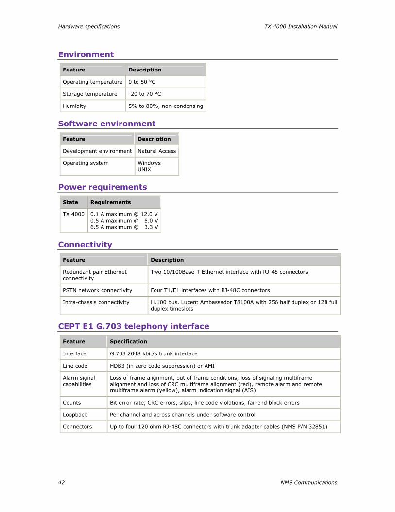
Environment
Feature Description
Operating temperature 0 to 50 °C
Storage temperature -20 to 70 °C
Humidity 5% to 80%, non-condensing
Software environment
Feature Description
Development environment Natural Access
Operating system Windows UNIX
Power requirements
State Requirements
TX 4000 0.1 A maximum @ 12.0 V 0.5 A maximum @ 5.0 V 6.5 A maximum @ 3.3 V
Connectivity
Feature Description
Redundant pair Ethernet connectivity
Two 10/100Base-T Ethernet interface with RJ-45 connectors
PSTN network connectivity Four T1/E1 interfaces with RJ-48C connectors
Intra-chassis connectivity H.100 bus. Lucent Ambassador T8100A with 256 half duplex or 128 full duplex timeslots
CEPT E1 G.703 telephony interface
Feature Specification
Interface G.703 2048 kbit/s trunk interface
Line code HDB3 (in zero code suppression) or AMI
Alarm signal capabilities
Loss of frame alignment, out of frame conditions, loss of signaling multiframe alignment and loss of CRC multiframe alignment (red), remote alarm and remote multiframe alarm (yellow), alarm indication signal (AIS)
Counts Bit error rate, CRC errors, slips, line code violations, far-end block errors
Loopback Per channel and across channels under software control
Connectors Up to four 120 ohm RJ-48C connectors with trunk adapter cables (NMS P/N 32851)
TX 4000 Installation Manual Hardware specifications
NMS Communications 43
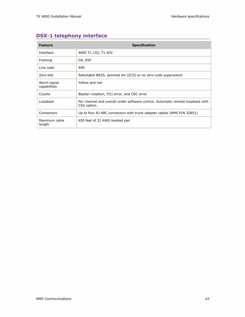
DSX-1 telephony interface
Feature Specification
Interface ANSI T1.102, T1.403
Framing D4, ESF
Line code AMI
Zero bits Selectable B8ZS, jammed bit (ZCS) or no zero code suppression
Alarm signal capabilities
Yellow and red
Counts Bipolar violation, F(t) error, and CRC error
Loopback Per channel and overall under software control. Automatic remote loopback with CSU option.
Connectors Up to four RJ-48C connectors with trunk adapter cables (NMS P/N 32851)
Maximum cable length
655 feet of 22 AWG twisted pair
Hardware specifications TX 4000 Installation Manual
44 NMS Communications
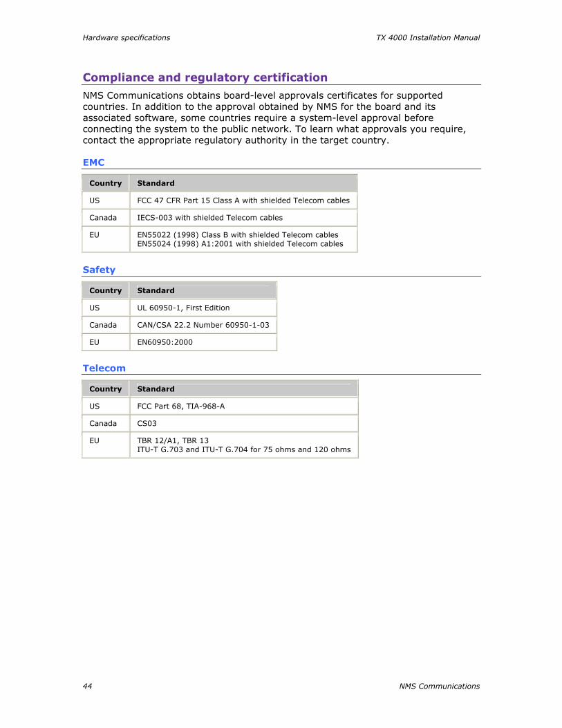
Compliance and regulatory certification
NMS Communications obtains board-level approvals certificates for supported countries. In addition to the approval obtained by NMS for the board and its associated software, some countries require a system-level approval before connecting the system to the public network. To learn what approvals you require, contact the appropriate regulatory authority in the target country.
EMC
Country Standard
US FCC 47 CFR Part 15 Class A with shielded Telecom cables
Canada IECS-003 with shielded Telecom cables
EU EN55022 (1998) Class B with shielded Telecom cables EN55024 (1998) A1:2001 with shielded Telecom cables
Safety
Country Standard
US UL 60950-1, First Edition
Canada CAN/CSA 22.2 Number 60950-1-03
EU EN60950:2000
Telecom
Country Standard
US FCC Part 68, TIA-968-A
Canada CS03
EU TBR 12/A1, TBR 13 ITU-T G.703 and ITU-T G.704 for 75 ohms and 120 ohms
NMS Communications 45
Index
A
adding a board 21
assigning a CP number 20
B
boot code LEDs 37
bracket 17
C
cables 13
cross-over 32
E1 network 31
for redundancy 33
T1 network 30
trunk adapter 27
CEPT E1 G.703 telephony interface 42
certifications 44
changing a CP number 22
communication processor (CP) 7
compliance certification 44
configuration utility 19
configuring the board 19
adding a board 21
assigning a CP number 20
changing a CP number 22
configuration utility 19
moving a board 23
removing a board 24
saving configuration changes 25
txcpcfg utility 19
configuring the hardware 15
DIP switches 15
H.100 bus termination 15
SS7 Monitor mode 16
connectivity 7, 42
connectors 27
CP number 19
assigning 20
changing 22
saving changes 25
cpcfg script 25
cpmodel utility 39
D
demonstration programs 10
diagnosing error conditions 16
DIP switches 15
DSX-1 telephony interface 43
E
E1 7
jacks 27
network connections 31
status LEDs 35
testing in loopback mode 32
environment 42, 42
Ethernet 7
connectors 29
for redundancy 33
LEDs 36
F
features 7, 41
H
H.100 bus 7, 41
H.100 bus termination 15
H.100 compliant interface 41
host interface 41
I
installing the board 14, 17
J
jacks 27
Index TX 4000 Installation Manual
46 NMS Communications
L
LEDs 35
board status 37
boot code 37
Ethernet 36
external status 35
status 38
loopback mode 32
N
Natural Access 9, 13
network connections 27
E1 31
for redundancy 33
T1 30
testing in loopback mode 32
NMS SS7 9, 13
P
pinouts 27
power requirements 42
R
recovering from error conditions 16
redundancy 33
dual node 33
single node 34
regulatory certification 44
requirements 9, 13
S
software components 9, 42
specifications 13
connectivity 42
environment 42
general features 41
H.100 compliant interface 41
host interface 41
power requirements 42
software environment 42
telephony interfaces 42
SS7 Monitor mode 16
status LEDs 38
system requirements 13
T
T1 7
jacks 27
network connections 30
status LEDs 35
testing in loopback mode 32
telephony interfaces 42, 43
txcpcfg utility 19
adding a board 21
assigning a CP number 20
changing a CP number 22
cpmodel utility 39
moving a board 23
removing a board 24
saving configuration changes 25
UNIX system 19
verifying the installation 39
Windows system 19
txdiag utility 39
U
utilities 10
using the configuration utility 19
verifying the installation 39
V
verifying the installation 39
board status LEDs 37
Ethernet LEDs 36
external connection LEDs 35