TWT42013I1.1 9500 MPR a Operations and Maintenance R3.03 SG CE
622
Copyright © 2012 Alcatel-Lucent. All Rights Reserved. COPYRIGHT © ALCATEL-LUCENT @@YEAR. ALL RIGHTS RESERVED. 9500 MPR (Microwave Packet Radio) Operations & Maintenance R3.03 (ANSI) STUDENT GUIDE TWT42013 Edition 1.1 Passing on and copying of this document, use and communication of its contents not permitted without written authorization from Alcatel-Lucent
-
Upload
kazihoque9082 -
Category
Documents
-
view
64 -
download
23
description
ALU MPR9500
Transcript of TWT42013I1.1 9500 MPR a Operations and Maintenance R3.03 SG CE
Copyright © 2012 Alcatel-Lucent. All Rights Reserved.
COPYRIGHT © ALCATEL-LUCENT @@YEAR. ALL RIGHTS RESERVED.
9500 MPR (Microwave Packet Radio)Operations & Maintenance R3.03 (ANSI)STUDENT GUIDETWT42013 Edition 1.1
Passing on and copying of this document, use and communication of its contents not permitted without written authorization from Alcatel-Lucent
Copyright © 2012 Alcatel-Lucent. All Rights Reserved.
Operations & Maintenance R3.03 (ANSI)9500 MPR (Microwave Packet Radio)2 COPYRIGHT © ALCATEL-LUCENT 2012. ALL RIGHTS RESERVED.
Terms of use and legal notices
Switch to notes view!TERMS OF USE AND LEGAL NOTICE Alcatel-Lucent provides this training course to you subject to these Terms of Use and Legal Notice. Your use of this training course and/or this site constitutes your acceptance of and agreement to these Terms of Use and Legal Notice. These Terms of Use and Legal Notice, as well as the contents of this training course, may be updated or amended by Alcatel-Lucent from time to time without prior notice to you. Your use of the Alcatel-Lucent training materials after such update or amendment constitutes your acceptance of and agreement to said updated or amended Terms of Use and Legal Notice.
SAFETY WARNINGAlcatel-Lucent training materials can be for products or refer to products that have both lethal and dangerous voltages present. Always observe all safety precautions and do not work on the equipment alone. The user is strongly advised not to wear conductive jewelry while working on the products. Equipment referred to or used during this course may be electrostatic sensitive. Please observe correct anti-static precautions.
PERMISSION TO USE CONTENT The information, communications, scripts, photos, text, video, graphics, music, sounds, images and other materials provided in this training course (collectively the "Content"), is intended for the lawful use of employees of Alcatel-Lucent and other authorized participants in this Alcatel-Lucent training course. You are hereby granted a non-exclusive, non-transferable permission to access and use the Content solely for your personal training and non-commercial use. This permission may be terminated by Alcatel-Lucent at any time for any reason or no reason, with or without notice. You must immediately cease use of the Content upon such termination.
COPYRIGHTS AND TRADEMARKSThe unauthorized copying, displaying or other use of any Content from this training course is a violation of the law and Alcatel-Lucent’s corporate policies. The Content is protected in France, the U.S. and other countries by a variety of laws, including but not limited to, copyright laws and treaty provisions, trademark laws, patent laws and other proprietary rights laws (collectively, "IP Rights"). In addition to Alcatel-Lucent’s IP Rights in the Content, in part and in whole, Alcatel-Lucent, and any of the third parties who have licensed and/or contributed to the Content, owns a copyright in the formatting and presentation of the Content.Alcatel-Lucent does not grant you any permission to use the Content other than the permission expressly stated in these Terms of Use and Legal Notice. All other use of Content from this training course, including, but not limited to, modification, publication, transmission, participation in the transfer or sale of, copying, reproduction, republishing, creation of derivative works from, distribution, performance, display, incorporation into another training course or presentation, or in any other way exploiting any of the Content, in whole or in part, for uses other than those expressly permitted herein is strictly prohibited and shall not be made without Alcatel-Lucent’s prior written consent. All characters appearing in this training course are fictitious. Any resemblance to real persons, living or dead, is purely coincidental.There may be a number of proprietary logos, marks, trademarks, slogans and product designations found in the Content. Alcatel, Lucent, Alcatel-Lucent and the Alcatel-Lucent logos are trademarks of Alcatel-Lucent. All other trademarks are the property of their respective owners. Alcatel-Lucent does not grant you a license to use any of the foregoing logos, marks, trademarks, slogans and product designations in any fashion. Granting of the right to access and use the Content for training purposes does not confer upon you any license under any of Alcatel-Lucent’s or any third party's IP Rights.
DISCLAIMERALCATEL-LUCENT DISCLAIMS ALL WARRANTIES REGARDING THE TRAINING COURSES OR THE CONTENT, EXPRESS OR IMPLIED, INCLUDING, WITHOUT LIMITATION, THE IMPLIED WARRANTIES OF MERCHANTABILITY OR FITNESS FOR A PARTICULAR PURPOSE. THE ALCATEL-LUCENT WILL NOT BE RESPONSIBLE OR LIABLE FOR ANY INJURY, LOSS, CLAIM, DAMAGE, OR ANY SPECIAL, EXEMPLARY, PUNITIVE, INDIRECT, INCIDENTAL OR CONSEQUENTIAL DAMAGES OF ANY KIND (INCLUDING WITHOUT LIMITATION LOSS PROFITS OR LOSS SAVINGS), WHETHER BASED IN CONTRACT, TORT, STRICT LIABILITY OR OTHERWISE, THAT ARISES OUT OF OR IS IN ANY WAY CONNECTED WITH (A) ANY USE OR MISUSE OF THE CONTENT OR THE TRAINING COURSES BY YOU, OR (B) ANY FAILURE OR DELAY BY ALCATEL-LUCENT, ITS OFFICERS, DIRECTORS, AGENTS OR EMPLOYEES IN CONNECTION WITH THE CONTENT OR THE TRAINING COURSES (INCLUDING, WITHOUT LIMITATION, THE USE OF OR INABILITY TO USE ANY COMPONENT OF THE CONTENT OR TRAINING BY YOU). SOME JURISDICTIONS LIMIT OR PROHIBIT SUCH EXCLUSION OF WARRANTIES OR LIMITATION OF LIABILITIES AND SO THE FOREGOING EXCLUSION OF WARRANTIES OR LIMITATION OF LIABILITY MAY NOT APPLY TO YOU.
GOVERNING LAWThese Terms of Use and Legal Notice are governed by the laws of France. The operation and use of the training course is governed by the laws of the country that governs your employment contract, if applicable. If any provision of these Terms of Use and Legal Notice, or the application thereto to a person or circumstance, is held invalid or unenforceable by law, statute or a court of competent jurisdiction, for any reason, then such provision shall be modified and/or superseded by a provision that reflects the intent of the original provision as closely as possible. All other provisions of these Terms of Use and Legal Notice shall remain in full force and effect. You may not assign these Terms of Use or any permission granted hereunder without Alcatel-Lucent’s prior written consent. Nothing herein shall be deemed an employment agreement or an offer of employment or an alteration in any way of a user’s terms of employment with or within Alcatel-Lucent. Copyright © 2011 Alcatel-Lucent. All Rights Reserved
Copyright © 2012 Alcatel-Lucent. All Rights Reserved.
Operations & Maintenance R3.03 (ANSI)9500 MPR (Microwave Packet Radio)3 COPYRIGHT © ALCATEL-LUCENT 2012. ALL RIGHTS RESERVED.
Course outline
4. Topic/Section is Positioned Here
5. Topic/Section is Positioned Here
6. Topic/Section is Positioned Here
7. Topic/Section is Positioned Here
1. ANSIModule 1. TWT42013-1 Course Overview
2. ProductModule 1. TWT42013-2 Overview
3. Product ArchitectureModule 1. TWT42013-3 MSS HardwareModule 2. TWT42013-4 MPT HardwareModule 3. TWT42013-5 Outdoor Hardware
4. NE OperationModule 1. TWT42013-6 Operator GUI InterfaceModule 2. TWT42013-7 Cross-ConnectionModule 3. TWT42013-8 Performance MonitoringModule 4. TWT42013-9 Alarm MonitorModule 5. TWT42013-10 Remove Cross ConnectionsModule 6. TWT42013-11 Browser Interface
5. CourseModule 1. TWT42013-12 Summary
6. TermsModule 1. TWT42013-13 Acronyms
7. ExercisesModule 1. TWT42013-14 Labs
Welcome to 9500 MPR (Microwave Packet Radio)
Operations & Maintenance R3.03 (ANSI)
Section 1. Course Overview
Module 1. Course Overview
Section 2. Product
Module 1. Product Overview
Section 3. Product Architecture
Module 1. MSS
Module 2. MPT-HL
Module 3. Outdoor Units
Section 4. Operation
Module 1. GUI
Module 2. Cross-Connections
Module 3. Diagnosis and Performance Monitoring
Module 4. Alarm Monitor/RSL History
Module 5. Remove Cross-Connections
Module 6. Browser
Section 5. Course
Module 1. Summary
Copyright © 2012 Alcatel-Lucent. All Rights Reserved.
Operations & Maintenance R3.03 (ANSI)9500 MPR (Microwave Packet Radio)4 COPYRIGHT © ALCATEL-LUCENT 2012. ALL RIGHTS RESERVED.
Course objectives
Upon completion of this course, you should be able to:
Describe equipment features, main applications, physical layout, external connections and the activation procedureUse the Craft Terminal and documentation for local configurationMonitor performance List probable cause of an alarm
Welcome to 9500 MPR (Microwave Packet Radio)
Operations & Maintenance R3.03 (ANSI)
Upon completion of this course, you should be able to:
Describe equipment features, main applications, physical layout, external connections and the activation procedureUse the Craft Terminal and documentation for local configurationMonitor performance List probable cause of an alarm
Your feedback is appreciated!Please feel free to Email your comments to:
Please include the following training reference in your email:TWT42013 Edition 1.1
Thank you!

Copyright © 2012 Alcatel-Lucent. All Rights Reserved.TWT42013-1 Edition 3.03
Section 1 · Module 1 · Page 1
Do not delete this graphic elements in here:
All Rights Reserved © Alcatel-Lucent @@YEAR
Module 1Course Overview
TWT42013-1 Edition 3.03
Section 1ANSI
9500 MPR (Microwave Packet Radio)Operations & Maintenance R3.03 (ANSI)
TWT42013 Edition 1.1
Copyright © 2012 Alcatel-Lucent. All Rights Reserved.TWT42013-1 Edition 3.03
Section 1 · Module 1 · Page 2
9500 MPR (Microwave Packet Radio) · Operations & Maintenance R3.03 (ANSI)ANSI · Course Overview1 · 1 · 2
COPYRIGHT © ALCATEL-LUCENT 2012. ALL RIGHTS RESERVED.
Blank page
This page is left blank intentionally
Revised to release 3.03Moehlenkamp, John2012-02-073.03
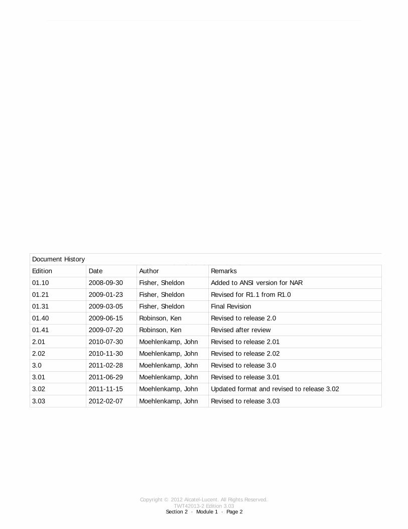
Document History
Edition Date Author Remarks
01.10 2008-09-30 Fisher, Sheldon Added to ANSI version for NAR
01.21 2009-01-23 Fisher, Sheldon Revised for R1.1 from R1.0
01.31 2009-03-05 Fisher, Sheldon Final Revision
01.40 2009-06-15 Robinson, Ken Revised to release 2.0
01.41 2009-07-20 Robinson, Ken Revised after review
2.01 2010-07-30 Moehlenkamp, John Revised to release 2.01
2.02 2010-11-30 Moehlenkamp, John Revised to release 2.02
3.0 2011-02-28 Moehlenkamp, John Revised to release 3.0
3.01 2011-06-29 Moehlenkamp, John Revised to release 3.01
3.02 2011-11-15 Moehlenkamp, John Updated format and revised to release 3.02
Copyright © 2012 Alcatel-Lucent. All Rights Reserved.TWT42013-1 Edition 3.03
Section 1 · Module 1 · Page 3
9500 MPR (Microwave Packet Radio) · Operations & Maintenance R3.03 (ANSI)ANSI · Course Overview1 · 1 · 3
COPYRIGHT © ALCATEL-LUCENT 2012. ALL RIGHTS RESERVED.
Course objectives
Upon completion of this course, you should be able to:
Describe the basic concepts of the 9500 MPR-ATurn-up and provision the systemRespond to and manage alarm conditionsMonitor system and application statusMaintain 9500 MPR-A hardware and software

Copyright © 2012 Alcatel-Lucent. All Rights Reserved.TWT42013-1 Edition 3.03
Section 1 · Module 1 · Page 4
9500 MPR (Microwave Packet Radio) · Operations & Maintenance R3.03 (ANSI)ANSI · Course Overview1 · 1 · 4
COPYRIGHT © ALCATEL-LUCENT 2012. ALL RIGHTS RESERVED.
Course objectives [cont.]
This page is left blank intentionally

Copyright © 2012 Alcatel-Lucent. All Rights Reserved.TWT42013-1 Edition 3.03
Section 1 · Module 1 · Page 5
9500 MPR (Microwave Packet Radio) · Operations & Maintenance R3.03 (ANSI)ANSI · Course Overview1 · 1 · 5
COPYRIGHT © ALCATEL-LUCENT 2012. ALL RIGHTS RESERVED.
References
The following documents support the 9500 MPR-A R3.02:9500 MPR Product Information 3EM23952AHAA9500 MPR Installation Practices 3EM23953AHAA9500 MPR Operation and Administration 3EM23954AHAA9500 MPR Turn-Up 3EM23955AHAA9500 MPR Maintenance and Trouble Clearing 3EM23956AHAA9500 MPR Engineering Support Documentation 3EM23957AHAA9500 MPR-A MPT-GC User Manual 3EM24569ADAA9500 MPR-A MPR-e User Manual 3EM24570ADAA9500 MPR-A MSS-1c User Manual 3EM24571ADAA
Product documentation is available on CD-ROM and online:CD-ROM Electronic Documentation 3EM23951AHAAOnline through Alcatel-Lucent’s OnLine Customer Support (OLCS) web site at: https://support.alcatel-lucent.com/portal/olcsHome.doProduct documentation updates appear on Alcatel-Lucent’s OLCS web site before they are available in any other format.
Copyright © 2012 Alcatel-Lucent. All Rights Reserved.TWT42013-1 Edition 3.03
Section 1 · Module 1 · Page 6
9500 MPR (Microwave Packet Radio) · Operations & Maintenance R3.03 (ANSI)ANSI · Course Overview1 · 1 · 6
COPYRIGHT © ALCATEL-LUCENT 2012. ALL RIGHTS RESERVED.
References [cont.]
Product Information 3EM23952AHAA:IntroductionSystem Administration Features Equipment Layout Unit DescriptionsFunctional Operation Engineering Specifications
Installation Practices 3EM23953AHAA
Operation and Administration 3EM23954AHAA:Provisioning and DeprovisioningEquipment FunctionsLog In to and Out of System Administer User ProfilesCross Connections . . .View Alarms and Abnormal Condition list . . . . . .View Current Configuration Data
Copyright © 2012 Alcatel-Lucent. All Rights Reserved.TWT42013-1 Edition 3.03
Section 1 · Module 1 · Page 7
9500 MPR (Microwave Packet Radio) · Operations & Maintenance R3.03 (ANSI)ANSI · Course Overview1 · 1 · 7
COPYRIGHT © ALCATEL-LUCENT 2012. ALL RIGHTS RESERVED.
References [cont.]
Turn-Up 3EM23955AHAA:OverviewSafety AwarenessElectrostatic Sensitive DevicesProduct Support Information
Maintenance and Trouble Clearing 3EM23956AHAA:Alarm and Abnormal Condition Clearing Procedures Equipment Replacement ProceduresFacility Alarms
Engineering Support Documentation 3EM23957AHAA
Copyright © 2012 Alcatel-Lucent. All Rights Reserved.TWT42013-1 Edition 3.03
Section 1 · Module 1 · Page 8
9500 MPR (Microwave Packet Radio) · Operations & Maintenance R3.03 (ANSI)ANSI · Course Overview1 · 1 · 8
COPYRIGHT © ALCATEL-LUCENT 2012. ALL RIGHTS RESERVED.
References [cont.]
MPT-GC (80 GHz Wireless Links) User Manual 3EM24569ADCC:Safety, EMC, EMF, ESD Norms and Equipment LabelingProduct Information and PlanningNE Management by Software ApplicationInstallationProvisioningMaintenance and Trouble-ClearingLine-UP and Commissioning
MPR-e (Outdoor units: MPT-HC V2 stand-alone) 3EM24570ADAA:Safety, EMC, EMF, ESD Norms and Equipment LabelingProduct Information and PlanningNE Management by Software ApplicationInstallationProvisioningMaintenance and Trouble-ClearingLine-UP and Commissioning
Copyright © 2012 Alcatel-Lucent. All Rights Reserved.TWT42013-1 Edition 3.03
Section 1 · Module 1 · Page 9
9500 MPR (Microwave Packet Radio) · Operations & Maintenance R3.03 (ANSI)ANSI · Course Overview1 · 1 · 9
COPYRIGHT © ALCATEL-LUCENT 2012. ALL RIGHTS RESERVED.
References [cont.]
Indoor: MSS-1c + Outdoor: MPT-HC V2 3EM24571ADAA:Safety, EMC, EMF, ESD Norms and Equipment LabelingProduct Information and PlanningNE Management by Software ApplicationInstallationProvisioningMaintenance and Trouble-ClearingLine-UP and Commissioning

Copyright © 2012 Alcatel-Lucent. All Rights Reserved.TWT42013-1 Edition 3.03
Section 1 · Module 1 · Page 10
9500 MPR (Microwave Packet Radio) · Operations & Maintenance R3.03 (ANSI)ANSI · Course Overview1 · 1 · 10
COPYRIGHT © ALCATEL-LUCENT 2012. ALL RIGHTS RESERVED.
End of moduleCourse Overview

Copyright © 2012 Alcatel-Lucent. All Rights Reserved.TWT42013-2 Edition 3.03
Section 2 · Module 1 · Page 1
Do not delete this graphic elements in here:
All Rights Reserved © Alcatel-Lucent @@YEAR
Module 1Overview
TWT42013-2 Edition 3.03
Section 2Product
9500 MPR (Microwave Packet Radio)Operations & Maintenance R3.03 (ANSI)
TWT42013 Edition 1.1
Copyright © 2012 Alcatel-Lucent. All Rights Reserved.TWT42013-2 Edition 3.03
Section 2 · Module 1 · Page 2
9500 MPR (Microwave Packet Radio) · Operations & Maintenance R3.03 (ANSI)Product · Overview2 · 1 · 2
COPYRIGHT © ALCATEL-LUCENT 2012. ALL RIGHTS RESERVED.
Blank page
This page is left blank intentionallyDocument History
Edition Date Author Remarks
01.10 2008-09-30 Fisher, Sheldon Added to ANSI version for NAR
01.21 2009-01-23 Fisher, Sheldon Revised for R1.1 from R1.0
01.31 2009-03-05 Fisher, Sheldon Final Revision
01.40 2009-06-15 Robinson, Ken Revised to release 2.0
01.41 2009-07-20 Robinson, Ken Revised after review
2.01 2010-07-30 Moehlenkamp, John Revised to release 2.01
2.02 2010-11-30 Moehlenkamp, John Revised to release 2.02
3.0 2011-02-28 Moehlenkamp, John Revised to release 3.0
3.01 2011-06-29 Moehlenkamp, John Revised to release 3.01
3.02 2011-11-15 Moehlenkamp, John Updated format and revised to release 3.02
3.03 2012-02-07 Moehlenkamp, John Revised to release 3.03
Copyright © 2012 Alcatel-Lucent. All Rights Reserved.TWT42013-2 Edition 3.03
Section 2 · Module 1 · Page 3
9500 MPR (Microwave Packet Radio) · Operations & Maintenance R3.03 (ANSI)Product · Overview2 · 1 · 3
COPYRIGHT © ALCATEL-LUCENT 2012. ALL RIGHTS RESERVED.
Module objectives
Upon completion of this module, you should be able to:
Describe the basic concepts of the 9500 MPR-A radioDescribe the features and advantages of the 9500 MPR-A radioDescribe the 9500 MPR-A radio hardwareDescribe data path from the Access to the transceivers

Copyright © 2012 Alcatel-Lucent. All Rights Reserved.TWT42013-2 Edition 3.03
Section 2 · Module 1 · Page 4
9500 MPR (Microwave Packet Radio) · Operations & Maintenance R3.03 (ANSI)Product · Overview2 · 1 · 4
COPYRIGHT © ALCATEL-LUCENT 2012. ALL RIGHTS RESERVED.
Module objectives [cont.]
This page is left blank intentionally

Copyright © 2012 Alcatel-Lucent. All Rights Reserved.TWT42013-2 Edition 3.03
9500 MPR (Microwave Packet Radio) · Operations & Maintenance R3.03 (ANSI)Product · Overview2 · 1 · 5
COPYRIGHT © ALCATEL-LUCENT 2012. ALL RIGHTS RESERVED.
Table of Contents
Switch to notes view! Page
1 Introduction to the 9500 MPR-A Radio 71.1 Classification of the New Generation Products 81.2 9500 MPR Introduction 91.3 MPR Family 101.4 MPR Family Hardware 111.5 Product Advantages - Multiservice Aggregation Layer 121.6 Product Advantages - Service Awareness 131.7 Product Advantages - Packet Node 141.8 Product Advantages - Service-driven Adaptive Modulation 151.9 Radio Link Aggregation 161.10 Cross-Polarized Interference Cancellation (XPIC) 181.11 Quality of Service 191.12 9500 MPR Network Management Solution 201.13 9500 MPR All Indoor Mount Arrangement 211.14 9500 MPR Split Mount Arrangement 221.15 9500 MPR Components 231.16 Control and Switching Module (CSM-E/Core-E) 241.17 Ethernet Access Switch (EAS/P8ETH) 251.18 MPT-HL 261.19 MPT-HL RF Connection (RF Filter) 271.20 TDM/PDH Access Modules 281.21 Access Modules 291.22 Radio Interface Modules 301.23 MSS Architecture 311.24 Product Overview 32

Copyright © 2012 Alcatel-Lucent. All Rights Reserved.TWT42013-2 Edition 3.03
9500 MPR (Microwave Packet Radio) · Operations & Maintenance R3.03 (ANSI)Product · Overview2 · 1 · 6
COPYRIGHT © ALCATEL-LUCENT 2012. ALL RIGHTS RESERVED.
Table of Contents [cont.]
Switch to notes view!
This page is left blank intentionally

Copyright © 2012 Alcatel-Lucent. All Rights Reserved.TWT42013-2 Edition 3.03
Section 2 · Module 1 · Page 7
9500 MPR (Microwave Packet Radio) · Operations & Maintenance R3.03 (ANSI)Product · Overview2 · 1 · 7
COPYRIGHT © ALCATEL-LUCENT 2012. ALL RIGHTS RESERVED.
1 Introduction to the 9500 MPR-A Radio
Copyright © 2012 Alcatel-Lucent. All Rights Reserved.TWT42013-2 Edition 3.03
Section 2 · Module 1 · Page 8
9500 MPR (Microwave Packet Radio) · Operations & Maintenance R3.03 (ANSI)Product · Overview2 · 1 · 8
COPYRIGHT © ALCATEL-LUCENT 2012. ALL RIGHTS RESERVED.
1 Introduction to the 9500 MPR-A Radio
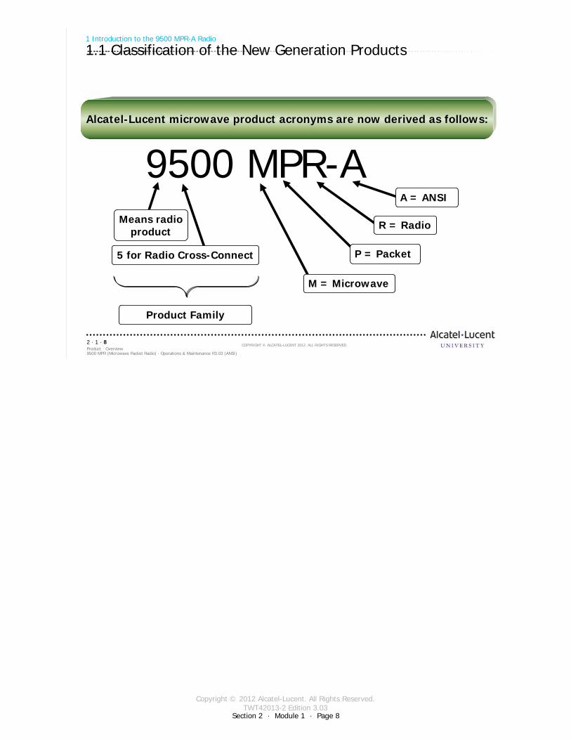
1.1 Classification of the New Generation Products
Alcatel-Lucent microwave product acronyms are now derived as follows:
9500 MPR9500 MPR--AA
Product Family
M = Microwave
P = Packet
R = Radio
A = ANSI
Means radioproduct
5 for Radio Cross-Connect
Copyright © 2012 Alcatel-Lucent. All Rights Reserved.TWT42013-2 Edition 3.03
Section 2 · Module 1 · Page 9
9500 MPR (Microwave Packet Radio) · Operations & Maintenance R3.03 (ANSI)Product · Overview2 · 1 · 9
COPYRIGHT © ALCATEL-LUCENT 2012. ALL RIGHTS RESERVED.
1 Introduction to the 9500 MPR-A Radio
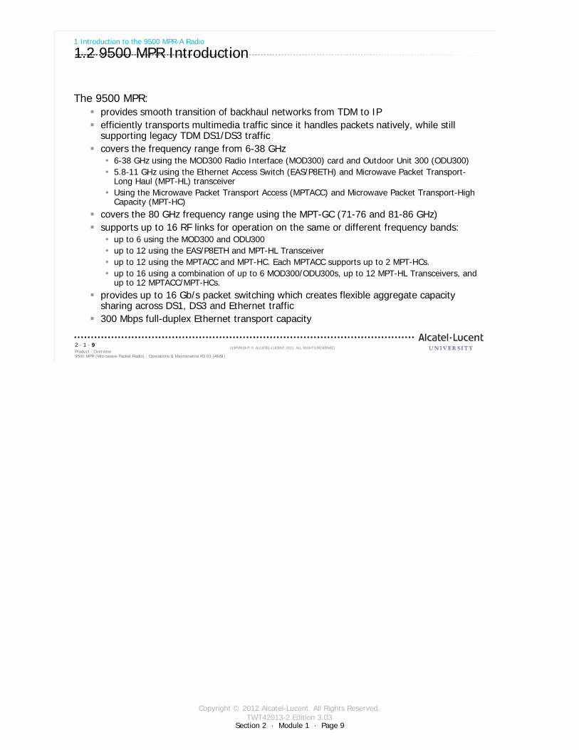
1.2 9500 MPR Introduction
The 9500 MPR:provides smooth transition of backhaul networks from TDM to IPefficiently transports multimedia traffic since it handles packets natively, while still supporting legacy TDM DS1/DS3 trafficcovers the frequency range from 6-38 GHz
6-38 GHz using the MOD300 Radio Interface (MOD300) card and Outdoor Unit 300 (ODU300)5.8-11 GHz using the Ethernet Access Switch (EAS/P8ETH) and Microwave Packet Transport-Long Haul (MPT-HL) transceiverUsing the Microwave Packet Transport Access (MPTACC) and Microwave Packet Transport-High Capacity (MPT-HC)
covers the 80 GHz frequency range using the MPT-GC (71-76 and 81-86 GHz)supports up to 16 RF links for operation on the same or different frequency bands:
up to 6 using the MOD300 and ODU300up to 12 using the EAS/P8ETH and MPT-HL Transceiverup to 12 using the MPTACC and MPT-HC. Each MPTACC supports up to 2 MPT-HCs.up to 16 using a combination of up to 6 MOD300/ODU300s, up to 12 MPT-HL Transceivers, and up to 12 MPTACC/MPT-HCs.
provides up to 16 Gb/s packet switching which creates flexible aggregate capacity sharing across DS1, DS3 and Ethernet traffic300 Mbps full-duplex Ethernet transport capacity
Copyright © 2012 Alcatel-Lucent. All Rights Reserved.TWT42013-2 Edition 3.03
Section 2 · Module 1 · Page 10
9500 MPR (Microwave Packet Radio) · Operations & Maintenance R3.03 (ANSI)Product · Overview2 · 1 · 10
COPYRIGHT © ALCATEL-LUCENT 2012. ALL RIGHTS RESERVED.
1 Introduction to the 9500 MPR-A Radio
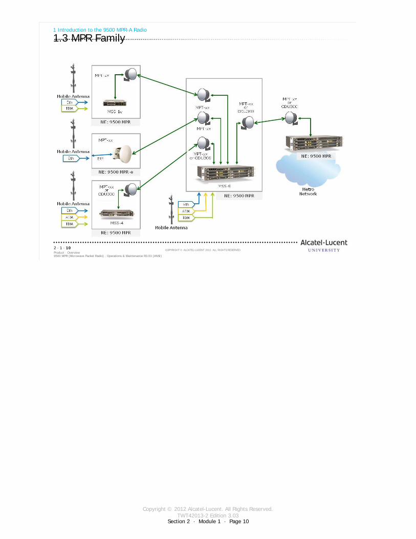
1.3 MPR Family
Copyright © 2012 Alcatel-Lucent. All Rights Reserved.TWT42013-2 Edition 3.03
Section 2 · Module 1 · Page 11
9500 MPR (Microwave Packet Radio) · Operations & Maintenance R3.03 (ANSI)Product · Overview2 · 1 · 11
COPYRIGHT © ALCATEL-LUCENT 2012. ALL RIGHTS RESERVED.
1 Introduction to the 9500 MPR-A Radio
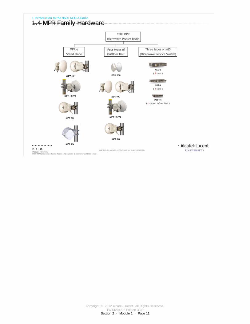
1.4 MPR Family Hardware
Copyright © 2012 Alcatel-Lucent. All Rights Reserved.TWT42013-2 Edition 3.03
Section 2 · Module 1 · Page 12
9500 MPR (Microwave Packet Radio) · Operations & Maintenance R3.03 (ANSI)Product · Overview2 · 1 · 12
COPYRIGHT © ALCATEL-LUCENT 2012. ALL RIGHTS RESERVED.
1 Introduction to the 9500 MPR-A Radio
1.5 Product Advantages - Multiservice Aggregation Layer
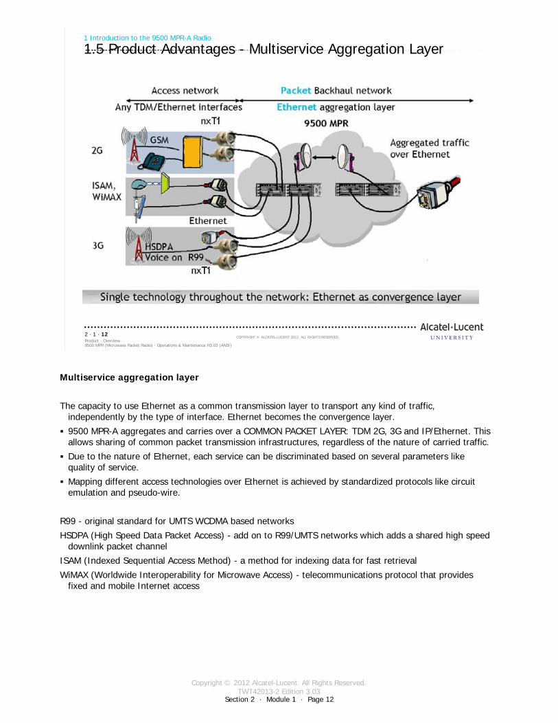
Multiservice aggregation layer
The capacity to use Ethernet as a common transmission layer to transport any kind of traffic, independently by the type of interface. Ethernet becomes the convergence layer.
9500 MPR-A aggregates and carries over a COMMON PACKET LAYER: TDM 2G, 3G and IP/Ethernet. This allows sharing of common packet transmission infrastructures, regardless of the nature of carried traffic.
Due to the nature of Ethernet, each service can be discriminated based on several parameters like quality of service.
Mapping different access technologies over Ethernet is achieved by standardized protocols like circuit emulation and pseudo-wire.
R99 - original standard for UMTS WCDMA based networks
HSDPA (High Speed Data Packet Access) - add on to R99/UMTS networks which adds a shared high speed downlink packet channel
ISAM (Indexed Sequential Access Method) - a method for indexing data for fast retrieval
WiMAX (Worldwide Interoperability for Microwave Access) - telecommunications protocol that provides fixed and mobile Internet access
Copyright © 2012 Alcatel-Lucent. All Rights Reserved.TWT42013-2 Edition 3.03
Section 2 · Module 1 · Page 13
9500 MPR (Microwave Packet Radio) · Operations & Maintenance R3.03 (ANSI)Product · Overview2 · 1 · 13
COPYRIGHT © ALCATEL-LUCENT 2012. ALL RIGHTS RESERVED.
1 Introduction to the 9500 MPR-A Radio
1.6 Product Advantages - Service Awareness
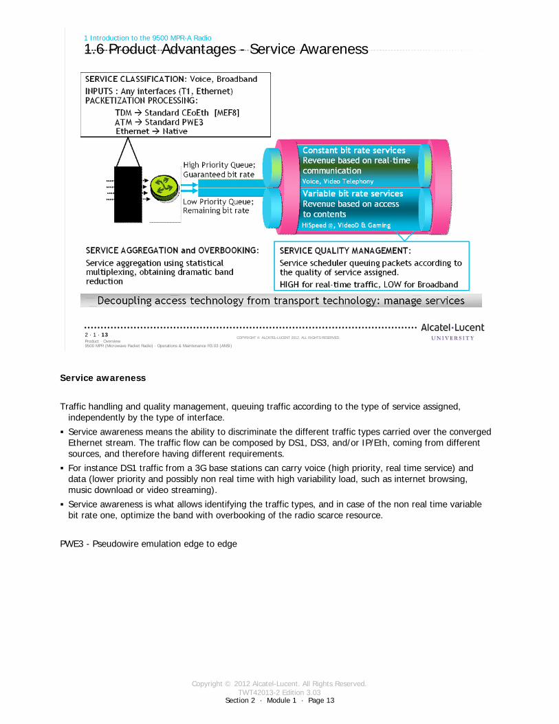
Service awareness
Traffic handling and quality management, queuing traffic according to the type of service assigned, independently by the type of interface.
Service awareness means the ability to discriminate the different traffic types carried over the converged Ethernet stream. The traffic flow can be composed by DS1, DS3, and/or IP/Eth, coming from different sources, and therefore having different requirements.
For instance DS1 traffic from a 3G base stations can carry voice (high priority, real time service) and data (lower priority and possibly non real time with high variability load, such as internet browsing, music download or video streaming).
Service awareness is what allows identifying the traffic types, and in case of the non real time variable bit rate one, optimize the band with overbooking of the radio scarce resource.
PWE3 - Pseudowire emulation edge to edge
Copyright © 2012 Alcatel-Lucent. All Rights Reserved.TWT42013-2 Edition 3.03
Section 2 · Module 1 · Page 14
9500 MPR (Microwave Packet Radio) · Operations & Maintenance R3.03 (ANSI)Product · Overview2 · 1 · 14
COPYRIGHT © ALCATEL-LUCENT 2012. ALL RIGHTS RESERVED.
1 Introduction to the 9500 MPR-A Radio
1.7 Product Advantages - Packet Node
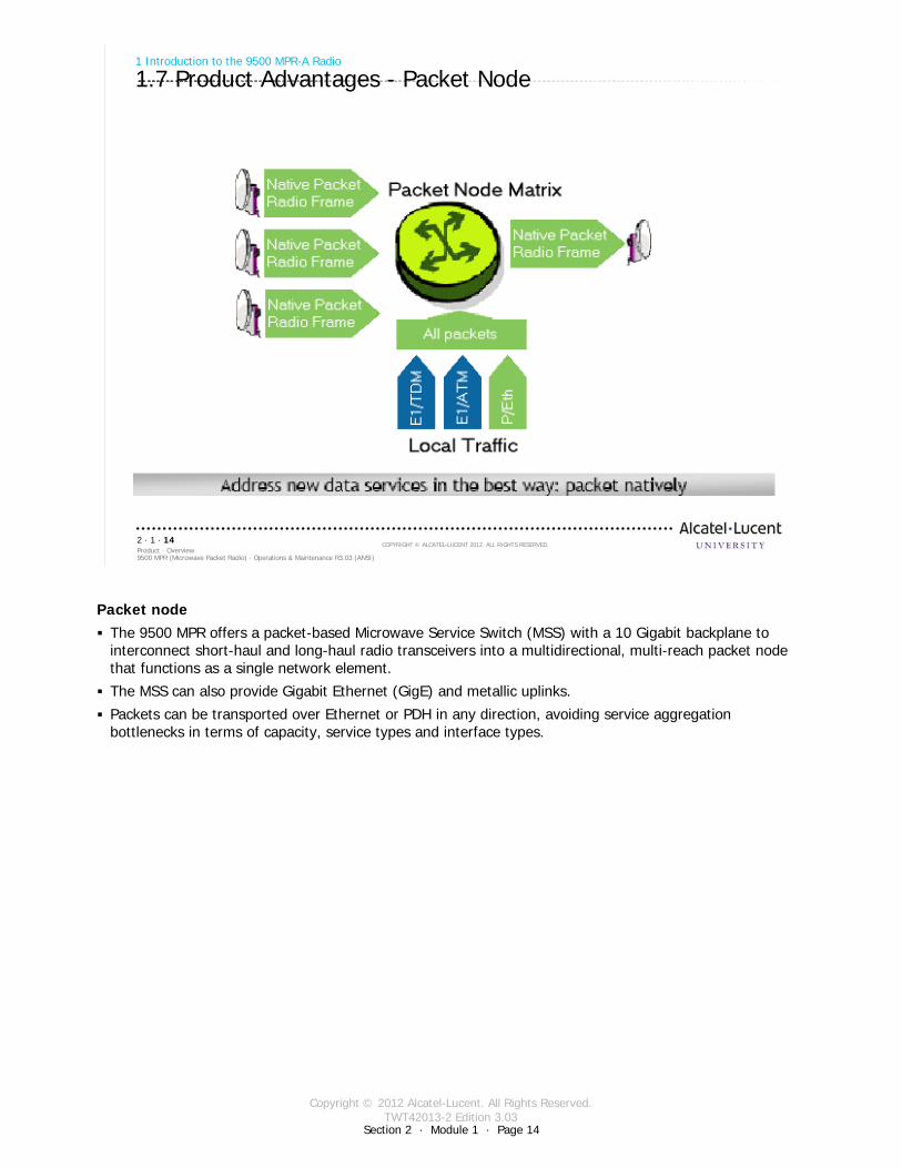
Packet nodeThe 9500 MPR offers a packet-based Microwave Service Switch (MSS) with a 10 Gigabit backplane to interconnect short-haul and long-haul radio transceivers into a multidirectional, multi-reach packet node that functions as a single network element.
The MSS can also provide Gigabit Ethernet (GigE) and metallic uplinks.
Packets can be transported over Ethernet or PDH in any direction, avoiding service aggregation bottlenecks in terms of capacity, service types and interface types.
Copyright © 2012 Alcatel-Lucent. All Rights Reserved.TWT42013-2 Edition 3.03
Section 2 · Module 1 · Page 15
9500 MPR (Microwave Packet Radio) · Operations & Maintenance R3.03 (ANSI)Product · Overview2 · 1 · 15
COPYRIGHT © ALCATEL-LUCENT 2012. ALL RIGHTS RESERVED.
1 Introduction to the 9500 MPR-A Radio
1.8 Product Advantages - Service-driven Adaptive Modulation
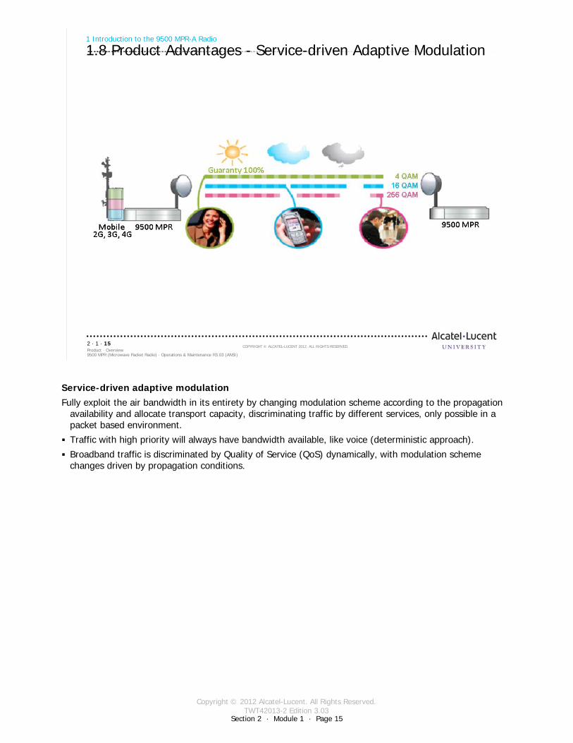
Service-driven adaptive modulationFully exploit the air bandwidth in its entirety by changing modulation scheme according to the propagation
availability and allocate transport capacity, discriminating traffic by different services, only possible in a packet based environment.
Traffic with high priority will always have bandwidth available, like voice (deterministic approach).
Broadband traffic is discriminated by Quality of Service (QoS) dynamically, with modulation scheme changes driven by propagation conditions.
Copyright © 2012 Alcatel-Lucent. All Rights Reserved.TWT42013-2 Edition 3.03
Section 2 · Module 1 · Page 16
9500 MPR (Microwave Packet Radio) · Operations & Maintenance R3.03 (ANSI)Product · Overview2 · 1 · 16
COPYRIGHT © ALCATEL-LUCENT 2012. ALL RIGHTS RESERVED.
1 Introduction to the 9500 MPR-A Radio
1.9 Radio Link Aggregation
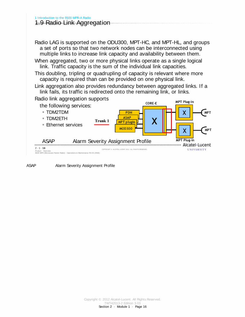
Radio LAG is supported on the ODU300, MPT-HC, and MPT-HL, and groups a set of ports so that two network nodes can be interconnected using multiple links to increase link capacity and availability between them.
When aggregated, two or more physical links operate as a single logical link. Traffic capacity is the sum of the individual link capacities.
This doubling, tripling or quadrupling of capacity is relevant where more capacity is required than can be provided on one physical link.
Link aggregation also provides redundancy between aggregated links. If a link fails, its traffic is redirected onto the remaining link, or links.
Radio link aggregation supports the following services:
TDM2TDMTDM2ETHEthernet services
ASAP Alarm Severity Assignment Profile
ASAP Alarm Severity Assignment Profile
Copyright © 2012 Alcatel-Lucent. All Rights Reserved.TWT42013-2 Edition 3.03
9500 MPR (Microwave Packet Radio) · Operations & Maintenance R3.03 (ANSI)Product · Overview2 · 1 · 17
COPYRIGHT © ALCATEL-LUCENT 2012. ALL RIGHTS RESERVED.
1 Introduction to the 9500 MPR-A Radio
1.9 Radio Link Aggregation [cont.]
Radio LAG size is restricted to the following:up to three Radio LAG ports per NEup to six MOD300/ODU300 ports per Radio LAG portup to six MPT-HC ports per Radio LAG portup to four MPT-HL ports per Radio LAG port
TMN inband should be cross-connected with only one radio interface of a radio LAG port
To add a radio port to a Radio LAG port, the radio port must not be provisioned as a member to any of the following:cross-connectionVLANport segregationPPP RF enabled on the radio channel
Section 2 · Module 1 · Page 17
Copyright © 2012 Alcatel-Lucent. All Rights Reserved.TWT42013-2 Edition 3.03
9500 MPR (Microwave Packet Radio) · Operations & Maintenance R3.03 (ANSI)Product · Overview2 · 1 · 18
COPYRIGHT © ALCATEL-LUCENT 2012. ALL RIGHTS RESERVED.
1 Introduction to the 9500 MPR-A Radio
1.10 Cross-Polarized Interference Cancellation (XPIC)
Cross-Polarized Interference Cancellation (XPIC) provides the ability to operate two links on the same radio channel frequency, one usingvertical polarization and the other using horizontal polarization. Supported on the MPT-HC only
XPIC typically provides 20 dB improvement in polarization discrimination. The actual improvement depends on the native discrimination provided by the antenna alignment and any reduction of this discrimination caused by atmospheric effects (fading)
XPIC supports the following radio configurations:Single 2x(1+0) XPICDouble 2x(1+1) HSB co-channel XPIC4x(1+0) XPIC
XPIC supports the following:Frequency: L6, U6, 7, 8, 11, 15, 18, and 23 GHzModulation: 128 and 256 QAMRadio channel spacing: 30, 40, and 50 MHz
Section 2 · Module 1 · Page 18
Copyright © 2012 Alcatel-Lucent. All Rights Reserved.TWT42013-2 Edition 3.03
9500 MPR (Microwave Packet Radio) · Operations & Maintenance R3.03 (ANSI)Product · Overview2 · 1 · 19
COPYRIGHT © ALCATEL-LUCENT 2012. ALL RIGHTS RESERVED.
1 Introduction to the 9500 MPR-A Radio
1.11 Quality of Service
The Quality of Service (QoS) feature assigns the priority for Ethernet packets according to the selected QoS mode. See Figure 6-9 for an overview of the QoS implementationQoS provides eight internal queues to support different traffic priorities. The QoS function assigns Ethernet packets to one of the eight egress traffic queuesQoS classification determines the method the system uses to assign packet priorityQoS classification criterion is assigned at the NE level and applied to all radio and Ethernet portsThe system supports the following QoS classification modes:
DisabledDiffServIEEE 802.1p
Section 2 · Module 1 · Page 19
Copyright © 2012 Alcatel-Lucent. All Rights Reserved.TWT42013-2 Edition 3.03
Section 2 · Module 1 · Page 20
9500 MPR (Microwave Packet Radio) · Operations & Maintenance R3.03 (ANSI)Product · Overview2 · 1 · 20
COPYRIGHT © ALCATEL-LUCENT 2012. ALL RIGHTS RESERVED.
1 Introduction to the 9500 MPR-A Radio
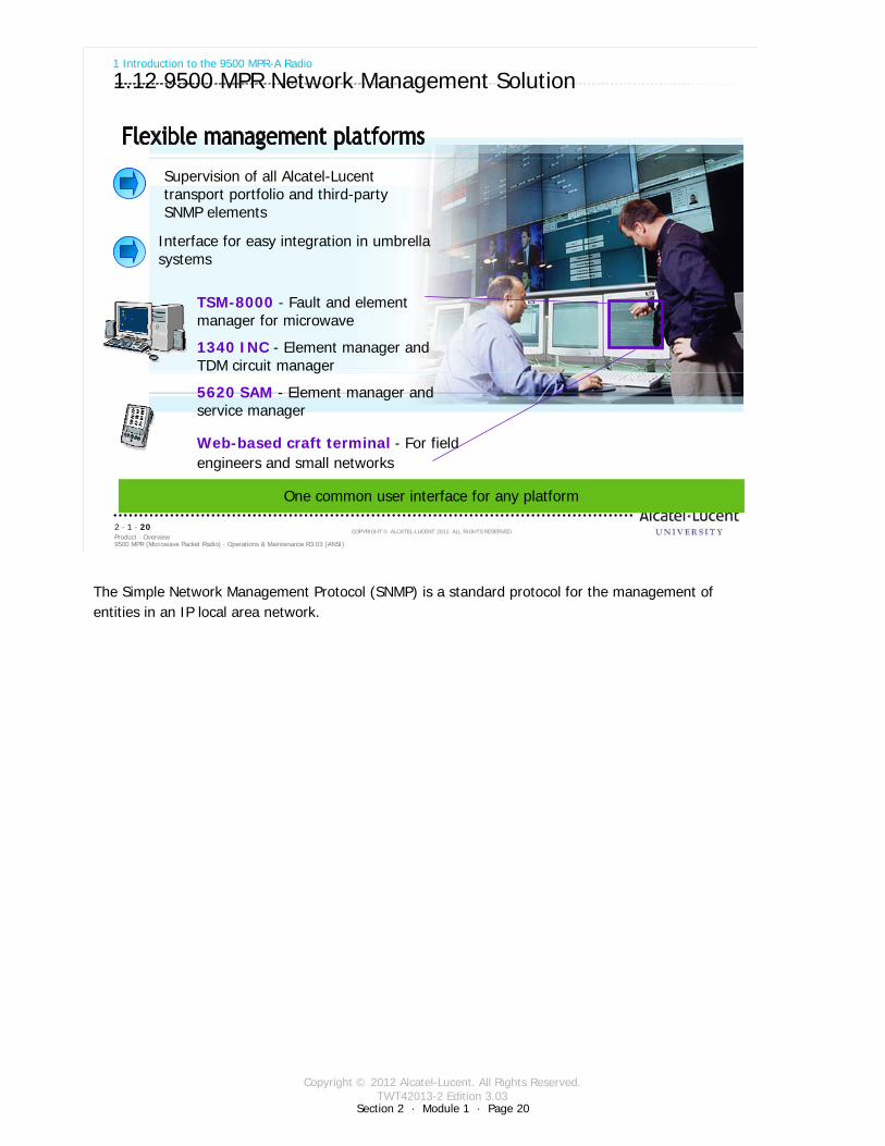
1.12 9500 MPR Network Management Solution
One common user interface for any platform
Supervision of all Alcatel-Lucent transport portfolio and third-party SNMP elements
Interface for easy integration in umbrella systems
1340 INC - Element manager and TDM circuit manager
5620 SAM - Element manager and service manager
Web-based craft terminal - For field engineers and small networks
TSM-8000 - Fault and element manager for microwave
The Simple Network Management Protocol (SNMP) is a standard protocol for the management of entities in an IP local area network.

Copyright © 2012 Alcatel-Lucent. All Rights Reserved.TWT42013-2 Edition 3.03
Section 2 · Module 1 · Page 21
9500 MPR (Microwave Packet Radio) · Operations & Maintenance R3.03 (ANSI)Product · Overview2 · 1 · 21
COPYRIGHT © ALCATEL-LUCENT 2012. ALL RIGHTS RESERVED.
1 Introduction to the 9500 MPR-A Radio
1.13 9500 MPR All Indoor Mount Arrangement
Up to 12 radio links per nodeUnprotected: (1+0, 2+0),1+1 HSB, SD, and FD radio protection nodeFrequencies: 5.8 Unlicensed, L6, U6, 10.5, and 11 GHzStatic and adaptive modulationBandwidths: 10 and 30 MHzModulations: 32, 128, and 256 QAM
MSS-4
MPT-HL MSS-8
No physical knobs, dials, or controls
or MSS-1c
Copyright © 2012 Alcatel-Lucent. All Rights Reserved.TWT42013-2 Edition 3.03
Section 2 · Module 1 · Page 22
9500 MPR (Microwave Packet Radio) · Operations & Maintenance R3.03 (ANSI)Product · Overview2 · 1 · 22
COPYRIGHT © ALCATEL-LUCENT 2012. ALL RIGHTS RESERVED.
1 Introduction to the 9500 MPR-A Radio
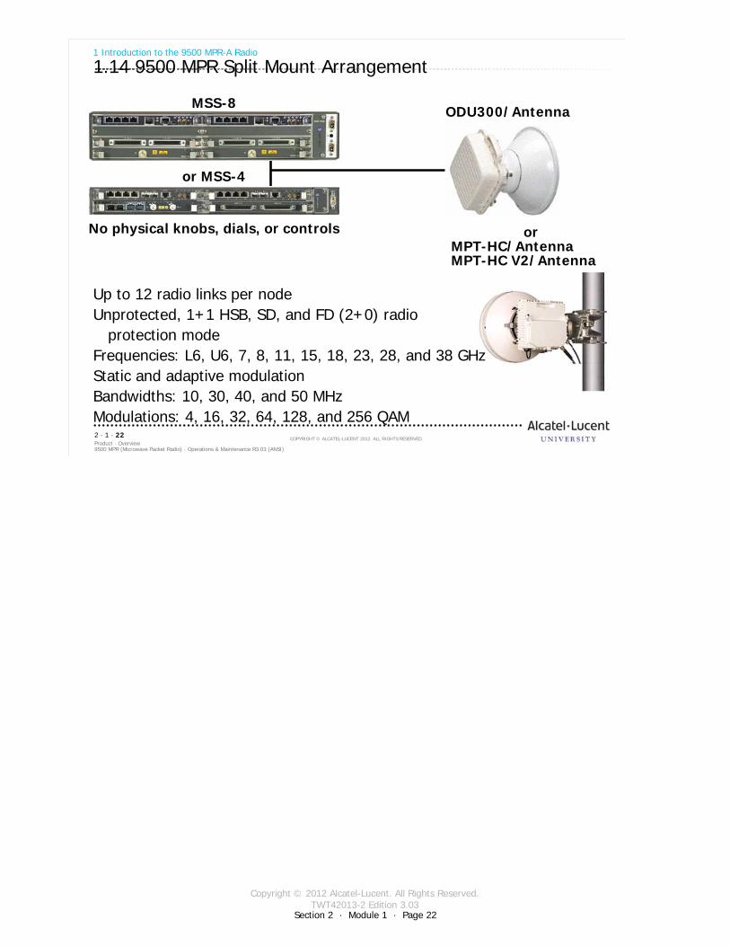
1.14 9500 MPR Split Mount Arrangement
or MSS-4
MSS-8
No physical knobs, dials, or controls
ODU300/Antenna
orMPT-HC/AntennaMPT-HC V2/Antenna
Up to 12 radio links per nodeUnprotected, 1+1 HSB, SD, and FD (2+0) radio
protection modeFrequencies: L6, U6, 7, 8, 11, 15, 18, 23, 28, and 38 GHzStatic and adaptive modulationBandwidths: 10, 30, 40, and 50 MHzModulations: 4, 16, 32, 64, 128, and 256 QAM
Copyright © 2012 Alcatel-Lucent. All Rights Reserved.TWT42013-2 Edition 3.03
Section 2 · Module 1 · Page 23
9500 MPR (Microwave Packet Radio) · Operations & Maintenance R3.03 (ANSI)Product · Overview2 · 1 · 23
COPYRIGHT © ALCATEL-LUCENT 2012. ALL RIGHTS RESERVED.
1 Introduction to the 9500 MPR-A Radio
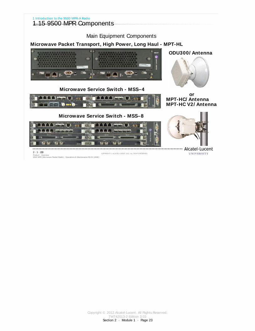
1.15 9500 MPR Components
Main Equipment Components
Microwave Service Switch Microwave Service Switch -- MSSMSS––88
Microwave Packet Transport, High Power, Long Haul Microwave Packet Transport, High Power, Long Haul -- MPTMPT--HLHL
ODU300/Antenna
Microwave Service Switch Microwave Service Switch -- MSSMSS––44or
MPT-HC/AntennaMPT-HC V2/Antenna
Copyright © 2012 Alcatel-Lucent. All Rights Reserved.TWT42013-2 Edition 3.03
Section 2 · Module 1 · Page 24
9500 MPR (Microwave Packet Radio) · Operations & Maintenance R3.03 (ANSI)Product · Overview2 · 1 · 24
COPYRIGHT © ALCATEL-LUCENT 2012. ALL RIGHTS RESERVED.
1 Introduction to the 9500 MPR-A Radio
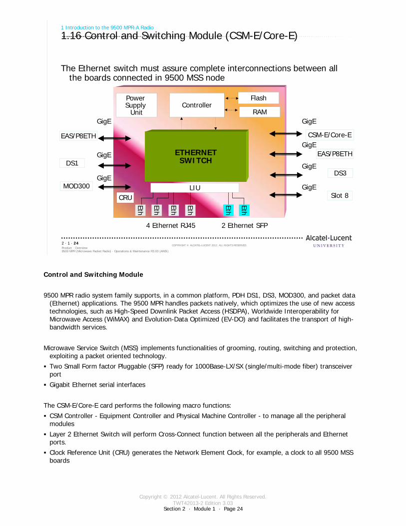
1.16 Control and Switching Module (CSM-E/Core-E)
The Ethernet switch must assure complete interconnections between all the boards connected in 9500 MSS node
Power Supply
UnitController
Flash
RAM
LIU
GigE
Eth
Eth
Eth
Eth
Eth
Eth
EAS/P8ETH
DS1
MOD300
CSM-E/Core-E
EAS/P8ETH
DS3
Slot 8
GigE
4 Ethernet RJ45 2 Ethernet SFP
CRU
GigE
GigEGigE
GigE
GigEETHERNETSWITCH
Control and Switching Module
9500 MPR radio system family supports, in a common platform, PDH DS1, DS3, MOD300, and packet data (Ethernet) applications. The 9500 MPR handles packets natively, which optimizes the use of new access technologies, such as High-Speed Downlink Packet Access (HSDPA), Worldwide Interoperability for Microwave Access (WiMAX) and Evolution-Data Optimized (EV-DO) and facilitates the transport of high-bandwidth services.
Microwave Service Switch (MSS) implements functionalities of grooming, routing, switching and protection, exploiting a packet oriented technology.
Two Small Form factor Pluggable (SFP) ready for 1000Base-LX/SX (single/multi-mode fiber) transceiver port
Gigabit Ethernet serial interfaces
The CSM-E/Core-E card performs the following macro functions:
CSM Controller - Equipment Controller and Physical Machine Controller - to manage all the peripheral modules
Layer 2 Ethernet Switch will perform Cross-Connect function between all the peripherals and Ethernet ports.
Clock Reference Unit (CRU) generates the Network Element Clock, for example, a clock to all 9500 MSS boards
Copyright © 2012 Alcatel-Lucent. All Rights Reserved.TWT42013-2 Edition 3.03
Section 2 · Module 1 · Page 25
9500 MPR (Microwave Packet Radio) · Operations & Maintenance R3.03 (ANSI)Product · Overview2 · 1 · 25
COPYRIGHT © ALCATEL-LUCENT 2012. ALL RIGHTS RESERVED.
1 Introduction to the 9500 MPR-A Radio
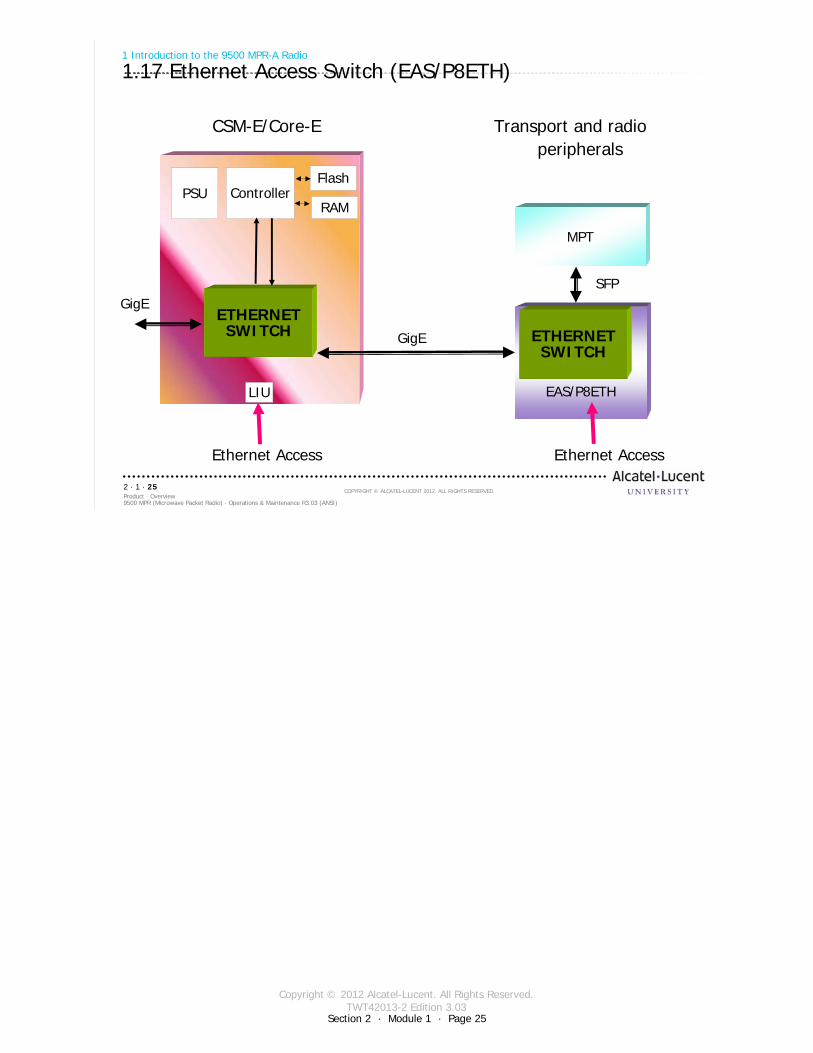
1.17 Ethernet Access Switch (EAS/P8ETH)
CSM-E/Core-E Transport and radioperipherals
PSU ControllerFlash
RAM
ETHERNETSWITCH
LIU
GigE
GigE
EAS/P8ETH
MPT
ETHERNETSWITCH
Ethernet AccessEthernet Access
SFP
Copyright © 2012 Alcatel-Lucent. All Rights Reserved.TWT42013-2 Edition 3.03
Section 2 · Module 1 · Page 26
9500 MPR (Microwave Packet Radio) · Operations & Maintenance R3.03 (ANSI)Product · Overview2 · 1 · 26
COPYRIGHT © ALCATEL-LUCENT 2012. ALL RIGHTS RESERVED.
1 Introduction to the 9500 MPR-A Radio
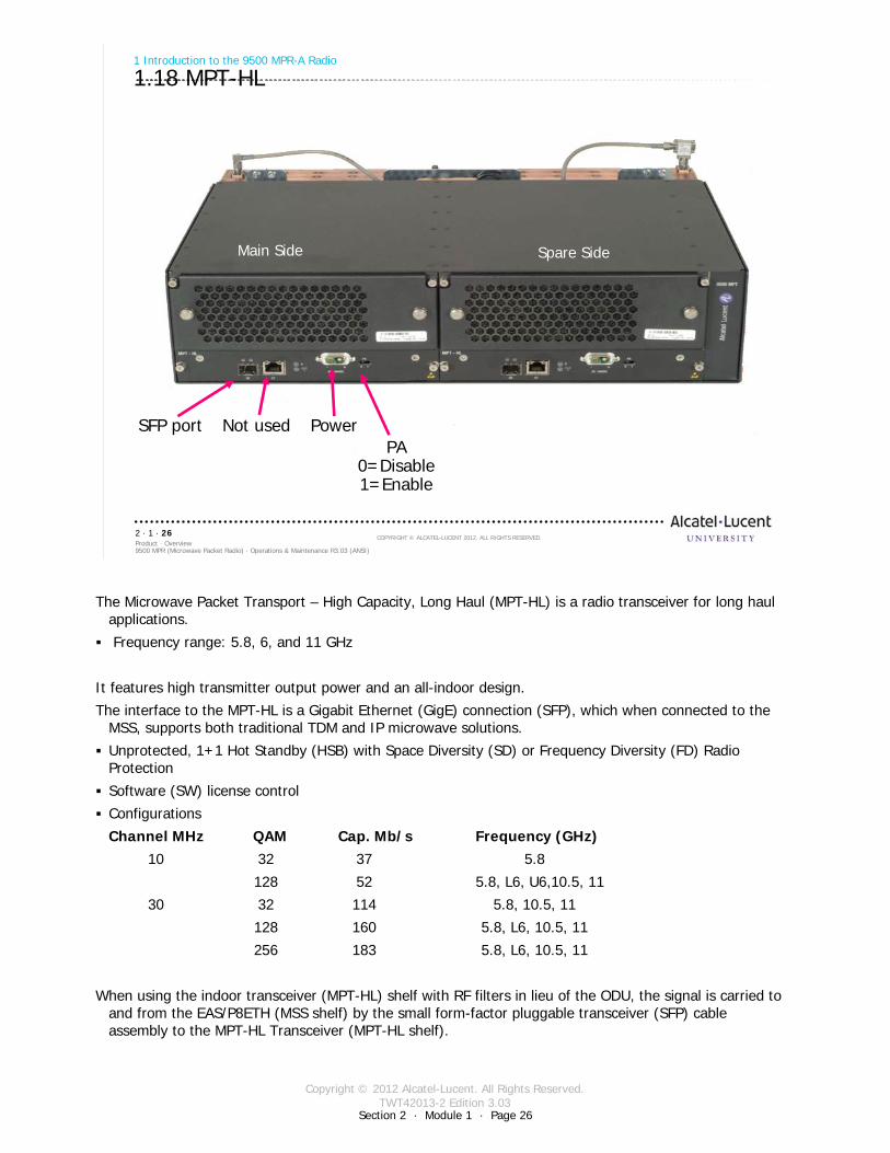
1.18 MPT-HL
Main Side Spare Side
SFP port Not used PowerPA
0=Disable1=Enable
The Microwave Packet Transport – High Capacity, Long Haul (MPT-HL) is a radio transceiver for long haul applications.
Frequency range: 5.8, 6, and 11 GHz
It features high transmitter output power and an all-indoor design.
The interface to the MPT-HL is a Gigabit Ethernet (GigE) connection (SFP), which when connected to the MSS, supports both traditional TDM and IP microwave solutions.
Unprotected, 1+1 Hot Standby (HSB) with Space Diversity (SD) or Frequency Diversity (FD) Radio Protection
Software (SW) license control
Configurations
Channel MHz QAM Cap. Mb/s Frequency (GHz)10 32 37 5.8
128 52 5.8, L6, U6,10.5, 11
30 32 114 5.8, 10.5, 11
128 160 5.8, L6, 10.5, 11
256 183 5.8, L6, 10.5, 11
When using the indoor transceiver (MPT-HL) shelf with RF filters in lieu of the ODU, the signal is carried to and from the EAS/P8ETH (MSS shelf) by the small form-factor pluggable transceiver (SFP) cable assembly to the MPT-HL Transceiver (MPT-HL shelf).
Copyright © 2012 Alcatel-Lucent. All Rights Reserved.TWT42013-2 Edition 3.03
Section 2 · Module 1 · Page 27
9500 MPR (Microwave Packet Radio) · Operations & Maintenance R3.03 (ANSI)Product · Overview2 · 1 · 27
COPYRIGHT © ALCATEL-LUCENT 2012. ALL RIGHTS RESERVED.
1 Introduction to the 9500 MPR-A Radio
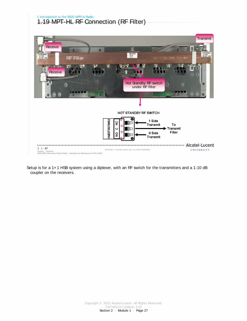
1.19 MPT-HL RF Connection (RF Filter)
RF Filter
Transmit
Receive
Hot Standby RF switch under RF filter
Receive
Setup is for a 1+1 HSB system using a diplexer, with an RF switch for the transmitters and a 1:10 dB coupler on the receivers.
Copyright © 2012 Alcatel-Lucent. All Rights Reserved.TWT42013-2 Edition 3.03
Section 2 · Module 1 · Page 28
9500 MPR (Microwave Packet Radio) · Operations & Maintenance R3.03 (ANSI)Product · Overview2 · 1 · 28
COPYRIGHT © ALCATEL-LUCENT 2012. ALL RIGHTS RESERVED.
1 Introduction to the 9500 MPR-A Radio
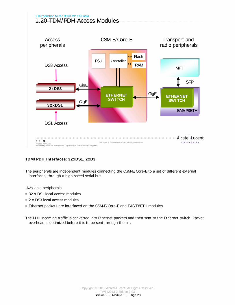
1.20 TDM/PDH Access Modules
32xDS1
PSU ControllerFlash
RAM
GigE
GigE
EAS/P8ETH
MPT
ETHERNETSWITCH
ETHERNETSWITCH
DS1 Access
2xDS3GigE
DS3 Access
Access CSM-E/Core-E Transport and peripherals radio peripherals
SFP
TDM/PDH Interfaces: 32xDS1, 2xD3
The peripherals are independent modules connecting the CSM-E/Core-E to a set of different external interfaces, through a high speed serial bus.
Available peripherals:
32 x DS1 local access modules
2 x DS3 local access modules
Ethernet packets are interfaced on the CSM-E/Core-E and EAS/P8ETH modules.
The PDH incoming traffic is converted into Ethernet packets and then sent to the Ethernet switch. Packet overhead is optimized before it is to be sent through the air.
Copyright © 2012 Alcatel-Lucent. All Rights Reserved.TWT42013-2 Edition 3.03
Section 2 · Module 1 · Page 29
9500 MPR (Microwave Packet Radio) · Operations & Maintenance R3.03 (ANSI)Product · Overview2 · 1 · 29
COPYRIGHT © ALCATEL-LUCENT 2012. ALL RIGHTS RESERVED.
1 Introduction to the 9500 MPR-A Radio
1.21 Access Modules
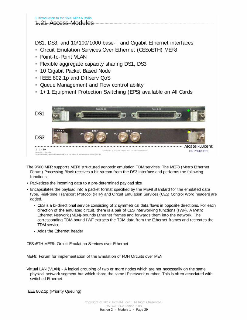
DS1, DS3, and 10/100/1000 base-T and Gigabit Ethernet interfacesCircuit Emulation Services Over Ethernet (CESoETH) MEF8Point-to-Point VLANFlexible aggregate capacity sharing DS1, DS310 Gigabit Packet Based NodeIEEE 802.1p and Diffserv QoSQueue Management and Flow control ability1+1 Equipment Protection Switching (EPS) available on All Cards
DS1
DS3
The 9500 MPR supports MEF8 structured agnostic emulation TDM services. The MEF8 (Metro Ethernet Forum) Processing Block receives a bit stream from the DS3 interface and performs the following functions:
Packetizes the incoming data to a pre-determined payload size
Encapsulates the payload into a packet format specified by the MEF8 standard for the emulated data type. Real-time Transport Protocol (RTP) and Circuit Emulation Services (CES) Control Word headers are added.
CES is a bi-directional service consisting of 2 symmetrical data flows in opposite directions. For each direction of the emulated circuit, there is a pair of CES interworking functions (IWF). A Metro Ethernet Network (MEN)-bounds Ethernet frames and forwards them into the network. The corresponding TDM-bound IWF extracts the TDM data from the Ethernet frames and recreates the TDM service.
Adds the Ethernet header
CESoETH MEF8: Circuit Emulation Services over Ethernet
MEF8: Forum for implementation of the Emulation of PDH Circuits over MEN
Virtual LAN (VLAN) - A logical grouping of two or more nodes which are not necessarily on the same physical network segment but which share the same IP network number. This is often associated with switched Ethernet.
IEEE 802.1p (Priority Queuing)
Copyright © 2012 Alcatel-Lucent. All Rights Reserved.TWT42013-2 Edition 3.03
Section 2 · Module 1 · Page 30
9500 MPR (Microwave Packet Radio) · Operations & Maintenance R3.03 (ANSI)Product · Overview2 · 1 · 30
COPYRIGHT © ALCATEL-LUCENT 2012. ALL RIGHTS RESERVED.
1 Introduction to the 9500 MPR-A Radio
1.22 Radio Interface Modules
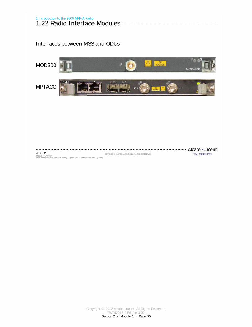
Interfaces between MSS and ODUs
MOD300
MPTACC
Copyright © 2012 Alcatel-Lucent. All Rights Reserved.TWT42013-2 Edition 3.03
Section 2 · Module 1 · Page 31
9500 MPR (Microwave Packet Radio) · Operations & Maintenance R3.03 (ANSI)Product · Overview2 · 1 · 31
COPYRIGHT © ALCATEL-LUCENT 2012. ALL RIGHTS RESERVED.
1 Introduction to the 9500 MPR-A Radio
1.23 MSS Architecture
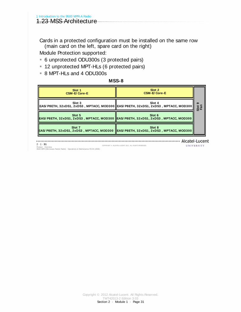
Cards in a protected configuration must be installed on the same row (main card on the left, spare card on the right)
Module Protection supported:6 unprotected ODU300s (3 protected pairs)12 unprotected MPT-HLs (6 protected pairs)8 MPT-HLs and 4 ODU300s
MSS-8
Slot 1CSM-E/Core-E
Slot 2CSM-E/Core-E
Slot 3EAS/P8ETH, 32xDS1, 2xDS3 , MPTACC, MOD300
Slot 4EAS/P8ETH, 32xDS1, 2xDS3 , MPTACC, MOD300
Slot 5EAS/P8ETH, 32xDS1, 2xDS3 , MPTACC, MOD300
Slot 6EAS/P8ETH, 32xDS1, 2xDS3 , MPTACC, MOD300
Slot 7EAS/P8ETH, 32xDS1, 2xDS3 , MPTACC, MOD300
Slot 8EAS/P8ETH, 32xDS1, 2xDS3 , MPTACC, MOD300
Slot
9Fa
n
Copyright © 2012 Alcatel-Lucent. All Rights Reserved.TWT42013-2 Edition 3.03
Section 2 · Module 1 · Page 32
9500 MPR (Microwave Packet Radio) · Operations & Maintenance R3.03 (ANSI)Product · Overview2 · 1 · 32
COPYRIGHT © ALCATEL-LUCENT 2012. ALL RIGHTS RESERVED.
1 Introduction to the 9500 MPR-A Radio
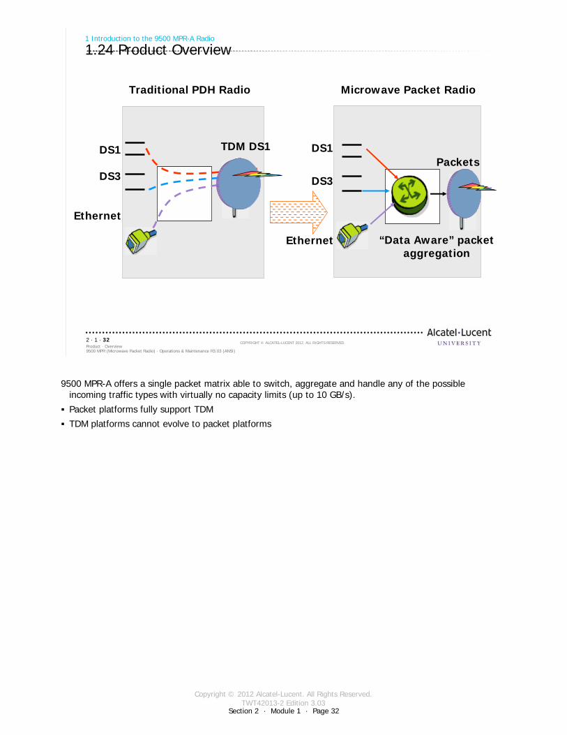
1.24 Product Overview
DS1
DS3
Ethernet
TDM DS1
Traditional PDH Radio
DS1
DS3
Ethernet “Data Aware” packetaggregation
Microwave Packet Radio
Packets
9500 MPR-A offers a single packet matrix able to switch, aggregate and handle any of the possible incoming traffic types with virtually no capacity limits (up to 10 GB/s).
Packet platforms fully support TDM
TDM platforms cannot evolve to packet platforms
Copyright © 2012 Alcatel-Lucent. All Rights Reserved.TWT42013-2 Edition 3.03
Section 2 · Module 1 · Page 33
9500 MPR (Microwave Packet Radio) · Operations & Maintenance R3.03 (ANSI)Product · Overview2 · 1 · 33
COPYRIGHT © ALCATEL-LUCENT 2012. ALL RIGHTS RESERVED.
Module summary
Basic concepts of the 9500 MPR-A RadioFeatures and advantages of the 9500 MPR-A Radio:
Multiservice aggregation layerService awarenessPacket node Network-management PlatformsIndoor transceiversODUs
The 9500 MPR-A Radio:Control and Switching Module (CSM-E/Core-E) Ethernet Access Switch (EAS/P8ETH) module Microwave Packet Transport – High Capacity, Long Haul (MPT-HL)MPT-HL RF Connection (RF Filter)Ethernet interfacesODUsRadio interface modulesAccess modules
Data path from the Access (Ethernet, DS3, and DS1) to the MPT-HLData path from the Access (Ethernet, DS3, and DS1) to the ODU Data path from the Access (Ethernet, DS3, and DS1) to the MPT-HC

Copyright © 2012 Alcatel-Lucent. All Rights Reserved.TWT42013-2 Edition 3.03
Section 2 · Module 1 · Page 34
9500 MPR (Microwave Packet Radio) · Operations & Maintenance R3.03 (ANSI)Product · Overview2 · 1 · 34
COPYRIGHT © ALCATEL-LUCENT 2012. ALL RIGHTS RESERVED.
End of moduleOverview

Copyright © 2012 Alcatel-Lucent. All Rights Reserved.TWT42013-3 Edition 3.03
Section 3 · Module 1 · Page 1
Do not delete this graphic elements in here:
All Rights Reserved © Alcatel-Lucent @@YEAR
Module 1MSS HardwareTWT42013-3 Edition 3.03
Section 3Product Architecture
9500 MPR (Microwave Packet Radio)Operations & Maintenance R3.03 (ANSI)
TWT42013 Edition 1.1
Copyright © 2012 Alcatel-Lucent. All Rights Reserved.TWT42013-3 Edition 3.03
Section 3 · Module 1 · Page 2
9500 MPR (Microwave Packet Radio) · Operations & Maintenance R3.03 (ANSI)Product Architecture · MSS Hardware3 · 1 · 2
COPYRIGHT © ALCATEL-LUCENT 2012. ALL RIGHTS RESERVED.
Blank page
This page is left blank intentionally
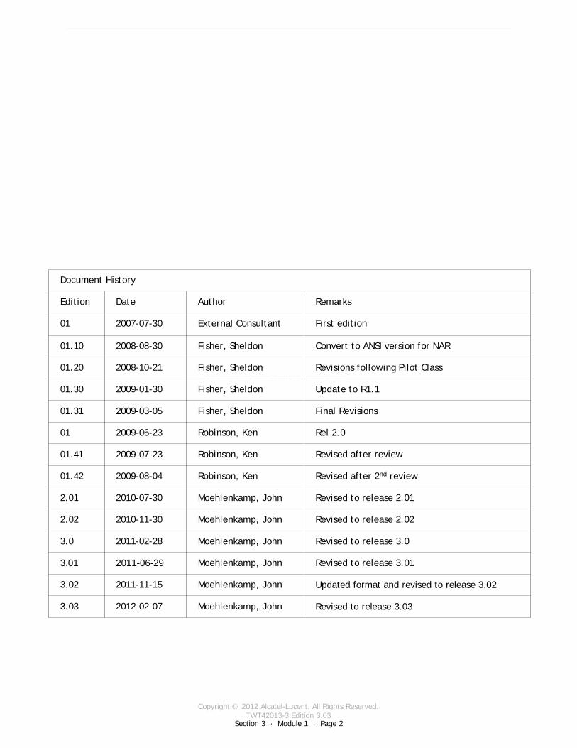
Revised to release 3.03Moehlenkamp, John2012-02-073.03
Document History
Edition Date Author Remarks
01 2007-07-30 External Consultant First edition
01.10 2008-08-30 Fisher, Sheldon Convert to ANSI version for NAR
01.20 2008-10-21 Fisher, Sheldon Revisions following Pilot Class
01.30 2009-01-30 Fisher, Sheldon Update to R1.1
01.31 2009-03-05 Fisher, Sheldon Final Revisions
01 2009-06-23 Robinson, Ken Rel 2.0
01.41 2009-07-23 Robinson, Ken Revised after review
01.42 2009-08-04 Robinson, Ken Revised after 2nd review
2.01 2010-07-30 Moehlenkamp, John Revised to release 2.01
2.02 2010-11-30 Moehlenkamp, John Revised to release 2.02
3.0 2011-02-28 Moehlenkamp, John Revised to release 3.0
3.01 2011-06-29 Moehlenkamp, John Revised to release 3.01
3.02 2011-11-15 Moehlenkamp, John Updated format and revised to release 3.02
Copyright © 2012 Alcatel-Lucent. All Rights Reserved.TWT42013-3 Edition 3.03
Section 3 · Module 1 · Page 3
9500 MPR (Microwave Packet Radio) · Operations & Maintenance R3.03 (ANSI)Product Architecture · MSS Hardware3 · 1 · 3
COPYRIGHT © ALCATEL-LUCENT 2012. ALL RIGHTS RESERVED.
Module objectives
Upon completion of this module, you should be able to:
Describe the functionality of each card of the MSS-4 and -8Control and Switching Module (CSM-E/Core-E)Ethernet Access Switch (EAS/P8ETH)DS1/P32E1DS1DS3/P2E3DS3MPTACCMOD300AUXFan
Describe the functionality of the +24/-48 Power ConverterDescribe the functionality of the MSS-1cDescribe patch panels (Distributors)

Copyright © 2012 Alcatel-Lucent. All Rights Reserved.TWT42013-3 Edition 3.03
Section 3 · Module 1 · Page 4
9500 MPR (Microwave Packet Radio) · Operations & Maintenance R3.03 (ANSI)Product Architecture · MSS Hardware3 · 1 · 4
COPYRIGHT © ALCATEL-LUCENT 2012. ALL RIGHTS RESERVED.
Module objectives [cont.]
This page is left blank intentionally
Copyright © 2012 Alcatel-Lucent. All Rights Reserved.TWT42013-3 Edition 3.03
9500 MPR (Microwave Packet Radio) · Operations & Maintenance R3.03 (ANSI)Product Architecture · MSS Hardware3 · 1 · 5
COPYRIGHT © ALCATEL-LUCENT 2012. ALL RIGHTS RESERVED.
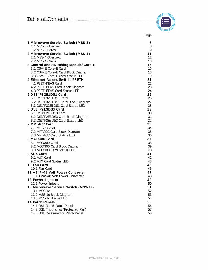
Table of Contents
Switch to notes view! Page
1 Microwave Service Switch (MSS-8) 71.1 MSS-8 Overview 81.2 MSS-8 Cards 9
2 Microwave Service Switch (MSS-4) 112.1 MSS-4 Overview 122.2 MSS-4 Cards 13
3 Control and Switching Module/Core-E 153.1 CSM-E/Core-E Card 163.2 CSM-E/Core-E Card Block Diagram 183.3 CSM-E/Core-E Card Status LED 19
4 Ethernet Access Switch/P8ETH 214.1 P8ETH/EAS Card 224.2 P8ETH/EAS Card Block Diagram 234.3 P8ETH/EAS Card Status LED 24
5 DS1/P32E1DS1 Card 255.1 DS1/P32E1DS1 Card 265.2 DS1/P32E1DS1 Card Block Diagram 275.3 DS1/P32E1DS1 Card Status LED 28
6 DS3/P2E3DS3 Card 296.1 DS3/P2E3DS3 Card 306.2 DS3/P2E3DS3 Card Block Diagram 316.3 DS3/P2E3DS3 Card Status LED 32
7 MPTACC Card 337.1 MPTACC Card 347.2 MPTACC Card Block Diagram 357.3 MPTACC Card Status LED 36
8 MOD300 Card 378.1 MOD300 Card 388.2 MOD300 Card Block Diagram 398.3 MOD300 Card Status LED 40
9 AUX Card 419.1 AUX Card 429.2 AUX Card Status LED 43
10 Fan Card 4510.1 Fan Card 46
11 +24/-48 Volt Power Converter 4711.1 +24/-48 Volt Power Converter 48
12 Power Injector 4912.1 Power Injector 50
13 Microwave Service Switch (MSS-1c) 5113.1 MSS-1c 5213.2 MSS-1c Block Diagram 5313.3 MSS-1c Status LED 54
14 Patch Panels 5514.1 DS1 RJ-45 Patch Panel 5614.2 DS1 Tributaries (Protected Pair) 5714.3 DS1 D-Connector Patch Panel 58

Copyright © 2012 Alcatel-Lucent. All Rights Reserved.TWT42013-3 Edition 3.03
9500 MPR (Microwave Packet Radio) · Operations & Maintenance R3.03 (ANSI)Product Architecture · MSS Hardware3 · 1 · 6
COPYRIGHT © ALCATEL-LUCENT 2012. ALL RIGHTS RESERVED.
Table of Contents [cont.]
Switch to notes view!
This page is left blank intentionally

Copyright © 2012 Alcatel-Lucent. All Rights Reserved.TWT42013-3 Edition 3.03
9500 MPR (Microwave Packet Radio) · Operations & Maintenance R3.03 (ANSI)Product Architecture · MSS Hardware3 · 1 · 7
COPYRIGHT © ALCATEL-LUCENT 2012. ALL RIGHTS RESERVED.
1 Microwave Service Switch (MSS-8)
Refer to 9500 MPR Product Information, 3EM23952AHAA, UDS-101 for more details
Section 3 · Module 1 · Page 7
Copyright © 2012 Alcatel-Lucent. All Rights Reserved.TWT42013-3 Edition 3.03
Section 3 · Module 1 · Page 8
9500 MPR (Microwave Packet Radio) · Operations & Maintenance R3.03 (ANSI)Product Architecture · MSS Hardware3 · 1 · 8
COPYRIGHT © ALCATEL-LUCENT 2012. ALL RIGHTS RESERVED.
1 Microwave Service Switch (MSS-8)
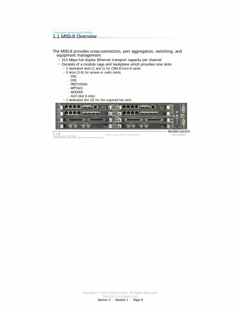
1.1 MSS-8 Overview
The MSS-8 provides cross-connection, port aggregation, switching, and equipment management.
314 Mbps full-duplex Ethernet transport capacity per channelConsists of a module cage and backplane which provides nine slots:
2 dedicated slots (1 and 2) for CSM-E/Core-E cards6 slots (3-8) for access or radio cards:
DS1DS3P8ETH/EASMPTACCMOD300AUX (slot 8 only)
1 dedicated slot (9) for the required fan card
1 2
3 49
5 6
7 8
Copyright © 2012 Alcatel-Lucent. All Rights Reserved.TWT42013-3 Edition 3.03
Section 3 · Module 1 · Page 9
9500 MPR (Microwave Packet Radio) · Operations & Maintenance R3.03 (ANSI)Product Architecture · MSS Hardware3 · 1 · 9
COPYRIGHT © ALCATEL-LUCENT 2012. ALL RIGHTS RESERVED.
1 Microwave Service Switch (MSS-8)
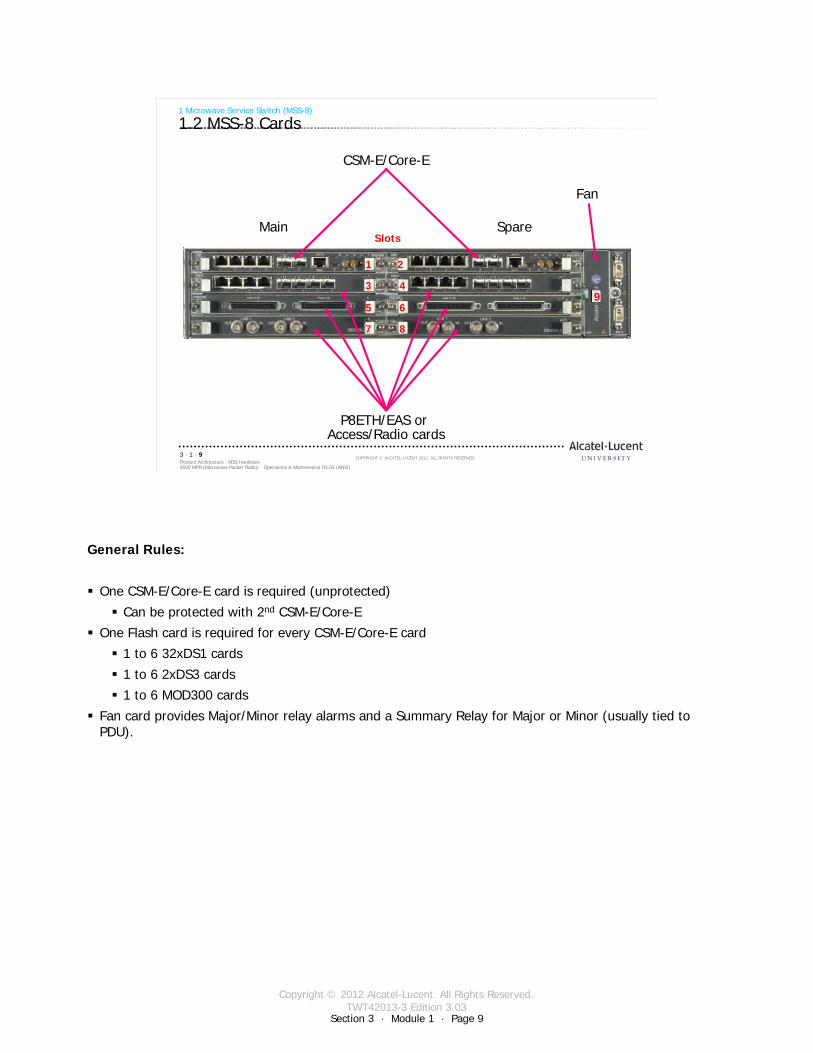
1.2 MSS-8 Cards
Slots
1 2
3 49
5 6
7 8
Main Spare
P8ETH/EAS or Access/Radio cards
CSM-E/Core-E
Fan
General Rules:
One CSM-E/Core-E card is required (unprotected)
Can be protected with 2nd CSM-E/Core-E
One Flash card is required for every CSM-E/Core-E card
1 to 6 32xDS1 cards
1 to 6 2xDS3 cards
1 to 6 MOD300 cards
Fan card provides Major/Minor relay alarms and a Summary Relay for Major or Minor (usually tied to PDU).

Copyright © 2012 Alcatel-Lucent. All Rights Reserved.TWT42013-3 Edition 3.03
Section 3 · Module 1 · Page 10
9500 MPR (Microwave Packet Radio) · Operations & Maintenance R3.03 (ANSI)Product Architecture · MSS Hardware3 · 1 · 10
COPYRIGHT © ALCATEL-LUCENT 2012. ALL RIGHTS RESERVED.
Blank page
Switch to notes view!
This page intentionally left blank

Copyright © 2012 Alcatel-Lucent. All Rights Reserved.TWT42013-3 Edition 3.03
9500 MPR (Microwave Packet Radio) · Operations & Maintenance R3.03 (ANSI)Product Architecture · MSS Hardware3 · 1 · 11
COPYRIGHT © ALCATEL-LUCENT 2012. ALL RIGHTS RESERVED.
2 Microwave Service Switch (MSS-4)
Refer to 9500 MPR Product Information, 3EM23952AHAA, UDS-117 for more details
Section 3 · Module 1 · Page 11
Copyright © 2012 Alcatel-Lucent. All Rights Reserved.TWT42013-3 Edition 3.03
Section 3 · Module 1 · Page 12
9500 MPR (Microwave Packet Radio) · Operations & Maintenance R3.03 (ANSI)Product Architecture · MSS Hardware3 · 1 · 12
COPYRIGHT © ALCATEL-LUCENT 2012. ALL RIGHTS RESERVED.
2 Microwave Service Switch (MSS-4)
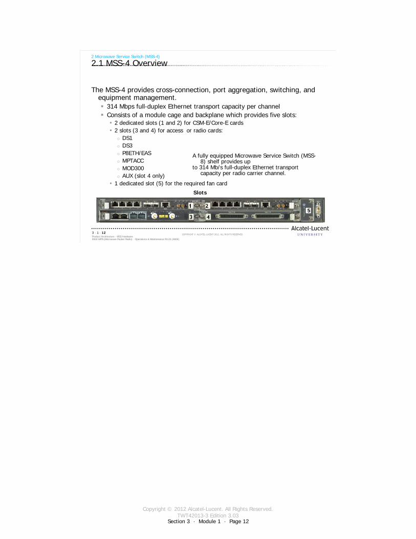
2.1 MSS-4 Overview
The MSS-4 provides cross-connection, port aggregation, switching, and equipment management.
314 Mbps full-duplex Ethernet transport capacity per channelConsists of a module cage and backplane which provides five slots:
2 dedicated slots (1 and 2) for CSM-E/Core-E cards2 slots (3 and 4) for access or radio cards:
DS1DS3P8ETH/EASMPTACCMOD300AUX (slot 4 only)
1 dedicated slot (5) for the required fan card
Slots
5
A fully equipped Microwave Service Switch (MSS-8) shelf provides up
to 314 Mb/s full-duplex Ethernet transport capacity per radio carrier channel.
Copyright © 2012 Alcatel-Lucent. All Rights Reserved.TWT42013-3 Edition 3.03
Section 3 · Module 1 · Page 13
9500 MPR (Microwave Packet Radio) · Operations & Maintenance R3.03 (ANSI)Product Architecture · MSS Hardware3 · 1 · 13
COPYRIGHT © ALCATEL-LUCENT 2012. ALL RIGHTS RESERVED.
2 Microwave Service Switch (MSS-4)
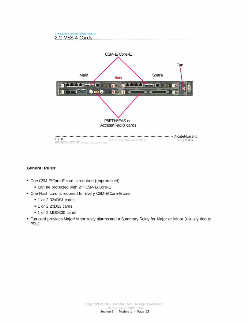
2.2 MSS-4 Cards
Main Spare
Fan
CSM-E/Core-E
P8ETH/EAS or Access/Radio cards
General Rules:
One CSM-E/Core-E card is required (unprotected)
Can be protected with 2nd CSM-E/Core-E
One Flash card is required for every CSM-E/Core-E card
1 or 2 32xDS1 cards
1 or 2 2xDS3 cards
1 or 2 MOD300 cards
Fan card provides Major/Minor relay alarms and a Summary Relay for Major or Minor (usually tied to PDU).

Copyright © 2012 Alcatel-Lucent. All Rights Reserved.TWT42013-3 Edition 3.03
Section 3 · Module 1 · Page 14
9500 MPR (Microwave Packet Radio) · Operations & Maintenance R3.03 (ANSI)Product Architecture · MSS Hardware3 · 1 · 14
COPYRIGHT © ALCATEL-LUCENT 2012. ALL RIGHTS RESERVED.
Blank page
Switch to notes view!
This page intentionally left blank

Copyright © 2012 Alcatel-Lucent. All Rights Reserved.TWT42013-3 Edition 3.03
9500 MPR (Microwave Packet Radio) · Operations & Maintenance R3.03 (ANSI)Product Architecture · MSS Hardware3 · 1 · 15
COPYRIGHT © ALCATEL-LUCENT 2012. ALL RIGHTS RESERVED.
3 Control and Switching Module/Core-E
Refer to 9500 MPR Product Information, 3EM23952AHAA, UDS-103 and UDS-111 for more details
Section 3 · Module 1 · Page 15
Copyright © 2012 Alcatel-Lucent. All Rights Reserved.TWT42013-3 Edition 3.03
Section 3 · Module 1 · Page 16
9500 MPR (Microwave Packet Radio) · Operations & Maintenance R3.03 (ANSI)Product Architecture · MSS Hardware3 · 1 · 16
COPYRIGHT © ALCATEL-LUCENT 2012. ALL RIGHTS RESERVED.
3 Control and Switching Module/Core-E
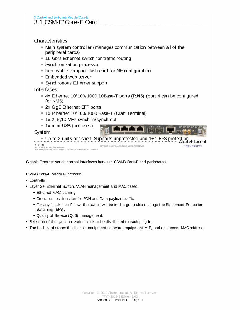
3.1 CSM-E/Core-E Card
CharacteristicsMain system controller (manages communication between all of theperipheral cards)16 Gb/s Ethernet switch for traffic routingSynchronization processorRemovable compact flash card for NE configurationEmbedded web serverSynchronous Ethernet support
Interfaces4x Ethernet 10/100/1000 10Base-T ports (RJ45) (port 4 can be configured for NMS)2x GigE Ethernet SFP ports1x Ethernet 10/100/1000 Base-T (Craft Terminal)1x 2, 5,10 MHz synch-in/synch-out1x mini-USB (not used)
SystemUp to 2 units per shelf. Supports unprotected and 1+1 EPS protection
Gigabit Ethernet serial internal interfaces between CSM-E/Core-E and peripherals
CSM-E/Core-E Macro Functions:
Controller
Layer 2+ Ethernet Switch, VLAN management and MAC based
Ethernet MAC learning
Cross-connect function for PDH and Data payload traffic;
For any “packetized” flow, the switch will be in charge to also manage the Equipment Protection Switching (EPS).
Quality of Service (QoS) management.
Selection of the synchronization clock to be distributed to each plug-in.
The flash card stores the license, equipment software, equipment MIB, and equipment MAC address.
Copyright © 2012 Alcatel-Lucent. All Rights Reserved.TWT42013-3 Edition 3.03
Section 3 · Module 1 · Page 17
9500 MPR (Microwave Packet Radio) · Operations & Maintenance R3.03 (ANSI)Product Architecture · MSS Hardware3 · 1 · 17
COPYRIGHT © ALCATEL-LUCENT 2012. ALL RIGHTS RESERVED.
3 Control and Switching Module/Core-E
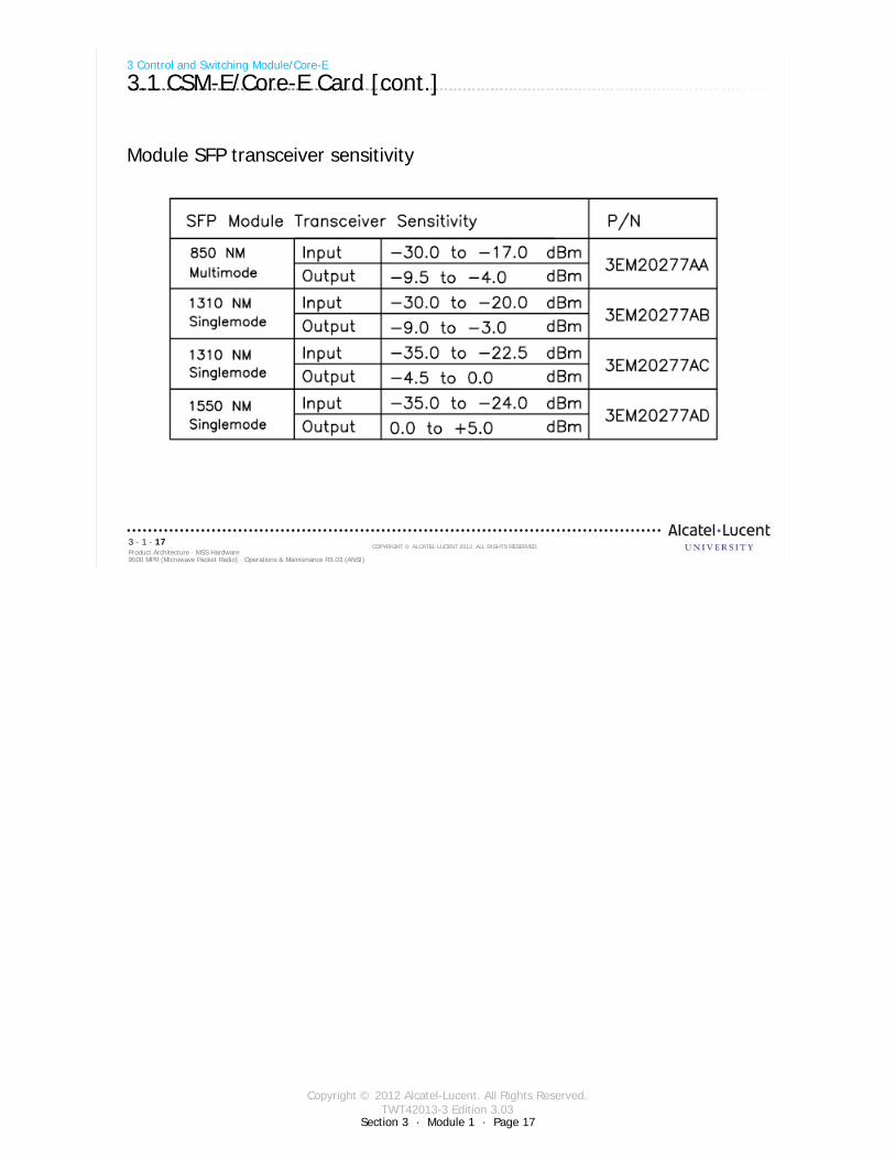
3.1 CSM-E/Core-E Card [cont.]
Module SFP transceiver sensitivity
Copyright © 2012 Alcatel-Lucent. All Rights Reserved.TWT42013-3 Edition 3.03
Section 3 · Module 1 · Page 18
9500 MPR (Microwave Packet Radio) · Operations & Maintenance R3.03 (ANSI)Product Architecture · MSS Hardware3 · 1 · 18
COPYRIGHT © ALCATEL-LUCENT 2012. ALL RIGHTS RESERVED.
3 Control and Switching Module/Core-E
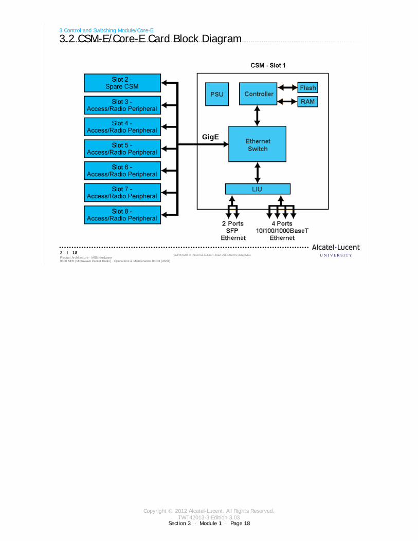
3.2 CSM-E/Core-E Card Block Diagram
GigE
Copyright © 2012 Alcatel-Lucent. All Rights Reserved.TWT42013-3 Edition 3.03
Section 3 · Module 1 · Page 19
9500 MPR (Microwave Packet Radio) · Operations & Maintenance R3.03 (ANSI)Product Architecture · MSS Hardware3 · 1 · 19
COPYRIGHT © ALCATEL-LUCENT 2012. ALL RIGHTS RESERVED.
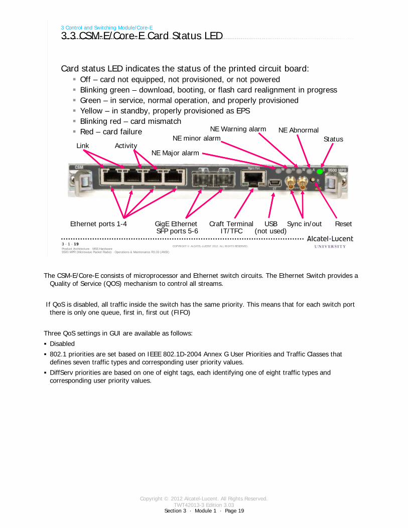
Card status LED indicates the status of the printed circuit board:Off – card not equipped, not provisioned, or not poweredBlinking green – download, booting, or flash card realignment in progressGreen – in service, normal operation, and properly provisionedYellow – in standby, properly provisioned as EPSBlinking red – card mismatchRed – card failure
3 Control and Switching Module/Core-E
3.3 CSM-E/Core-E Card Status LED
StatusNE Abnormal
NE Major alarm
NE Warning alarmNE minor alarm
Ethernet ports 1-4 GigE Ethernet SFP ports 5-6
Craft TerminalIT/TFC
Sync in/out Reset
Link Activity
USB(not used)
The CSM-E/Core-E consists of microprocessor and Ethernet switch circuits. The Ethernet Switch provides a Quality of Service (QOS) mechanism to control all streams.
If QoS is disabled, all traffic inside the switch has the same priority. This means that for each switch port there is only one queue, first in, first out (FIFO)
Three QoS settings in GUI are available as follows:
Disabled
802.1 priorities are set based on IEEE 802.1D-2004 Annex G User Priorities and Traffic Classes that defines seven traffic types and corresponding user priority values.
DiffServ priorities are based on one of eight tags, each identifying one of eight traffic types and corresponding user priority values.

Copyright © 2012 Alcatel-Lucent. All Rights Reserved.TWT42013-3 Edition 3.03
Section 3 · Module 1 · Page 20
9500 MPR (Microwave Packet Radio) · Operations & Maintenance R3.03 (ANSI)Product Architecture · MSS Hardware3 · 1 · 20
COPYRIGHT © ALCATEL-LUCENT 2012. ALL RIGHTS RESERVED.
Blank page
Switch to notes view!
This page intentionally left blank

Copyright © 2012 Alcatel-Lucent. All Rights Reserved.TWT42013-3 Edition 3.03
9500 MPR (Microwave Packet Radio) · Operations & Maintenance R3.03 (ANSI)Product Architecture · MSS Hardware3 · 1 · 21
COPYRIGHT © ALCATEL-LUCENT 2012. ALL RIGHTS RESERVED.
4 Ethernet Access Switch/P8ETH
Refer to 9500 MPR Product Information, 3EM23952AHAA, UDS-107 for more details
Section 3 · Module 1 · Page 21
Copyright © 2012 Alcatel-Lucent. All Rights Reserved.TWT42013-3 Edition 3.03
Section 3 · Module 1 · Page 22
9500 MPR (Microwave Packet Radio) · Operations & Maintenance R3.03 (ANSI)Product Architecture · MSS Hardware3 · 1 · 22
COPYRIGHT © ALCATEL-LUCENT 2012. ALL RIGHTS RESERVED.
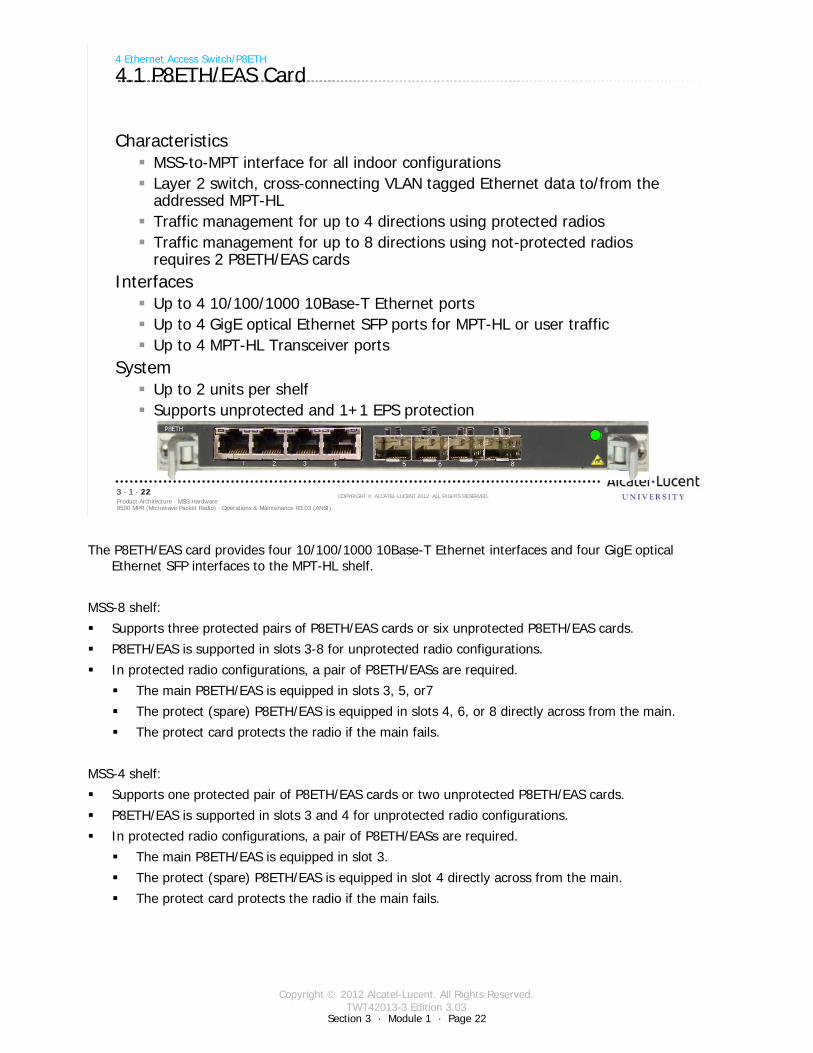
CharacteristicsMSS-to-MPT interface for all indoor configurationsLayer 2 switch, cross-connecting VLAN tagged Ethernet data to/from the addressed MPT-HLTraffic management for up to 4 directions using protected radiosTraffic management for up to 8 directions using not-protected radios requires 2 P8ETH/EAS cards
InterfacesUp to 4 10/100/1000 10Base-T Ethernet portsUp to 4 GigE optical Ethernet SFP ports for MPT-HL or user trafficUp to 4 MPT-HL Transceiver ports
SystemUp to 2 units per shelfSupports unprotected and 1+1 EPS protection
4 Ethernet Access Switch/P8ETH
4.1 P8ETH/EAS Card
The P8ETH/EAS card provides four 10/100/1000 10Base-T Ethernet interfaces and four GigE optical Ethernet SFP interfaces to the MPT-HL shelf.
MSS-8 shelf:
Supports three protected pairs of P8ETH/EAS cards or six unprotected P8ETH/EAS cards.
P8ETH/EAS is supported in slots 3-8 for unprotected radio configurations.
In protected radio configurations, a pair of P8ETH/EASs are required.
The main P8ETH/EAS is equipped in slots 3, 5, or7
The protect (spare) P8ETH/EAS is equipped in slots 4, 6, or 8 directly across from the main.
The protect card protects the radio if the main fails.
MSS-4 shelf:
Supports one protected pair of P8ETH/EAS cards or two unprotected P8ETH/EAS cards.
P8ETH/EAS is supported in slots 3 and 4 for unprotected radio configurations.
In protected radio configurations, a pair of P8ETH/EASs are required.
The main P8ETH/EAS is equipped in slot 3.
The protect (spare) P8ETH/EAS is equipped in slot 4 directly across from the main.
The protect card protects the radio if the main fails.
Copyright © 2012 Alcatel-Lucent. All Rights Reserved.TWT42013-3 Edition 3.03
Section 3 · Module 1 · Page 23
9500 MPR (Microwave Packet Radio) · Operations & Maintenance R3.03 (ANSI)Product Architecture · MSS Hardware3 · 1 · 23
COPYRIGHT © ALCATEL-LUCENT 2012. ALL RIGHTS RESERVED.
4 Ethernet Access Switch/P8ETH
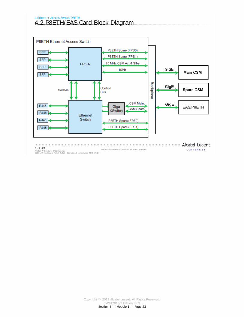
4.2 P8ETH/EAS Card Block Diagram
Copyright © 2012 Alcatel-Lucent. All Rights Reserved.TWT42013-3 Edition 3.03
Section 3 · Module 1 · Page 24
9500 MPR (Microwave Packet Radio) · Operations & Maintenance R3.03 (ANSI)Product Architecture · MSS Hardware3 · 1 · 24
COPYRIGHT © ALCATEL-LUCENT 2012. ALL RIGHTS RESERVED.
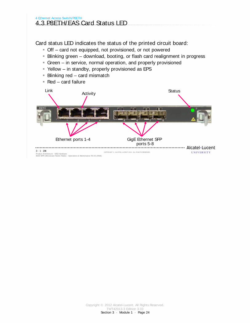
Card status LED indicates the status of the printed circuit board:Off – card not equipped, not provisioned, or not poweredBlinking green – download, booting, or flash card realignment in progressGreen – in service, normal operation, and properly provisionedYellow – in standby, properly provisioned as EPSBlinking red – card mismatchRed – card failure
4 Ethernet Access Switch/P8ETH
4.3 P8ETH/EAS Card Status LED
StatusLink
Ethernet ports 1-4 GigE Ethernet SFP ports 5-8
Activity

Copyright © 2012 Alcatel-Lucent. All Rights Reserved.TWT42013-3 Edition 3.03
9500 MPR (Microwave Packet Radio) · Operations & Maintenance R3.03 (ANSI)Product Architecture · MSS Hardware3 · 1 · 25
COPYRIGHT © ALCATEL-LUCENT 2012. ALL RIGHTS RESERVED.
5 DS1/P32E1DS1 Card
Refer to 9500 MPR Product Information, 3EM23952AHAA, UDS-105 for more details
Section 3 · Module 1 · Page 25
Copyright © 2012 Alcatel-Lucent. All Rights Reserved.TWT42013-3 Edition 3.03
Section 3 · Module 1 · Page 26
9500 MPR (Microwave Packet Radio) · Operations & Maintenance R3.03 (ANSI)Product Architecture · MSS Hardware3 · 1 · 26
COPYRIGHT © ALCATEL-LUCENT 2012. ALL RIGHTS RESERVED.
5 DS1/P32E1DS1 Card
5.1 DS1/P32E1DS1 Card
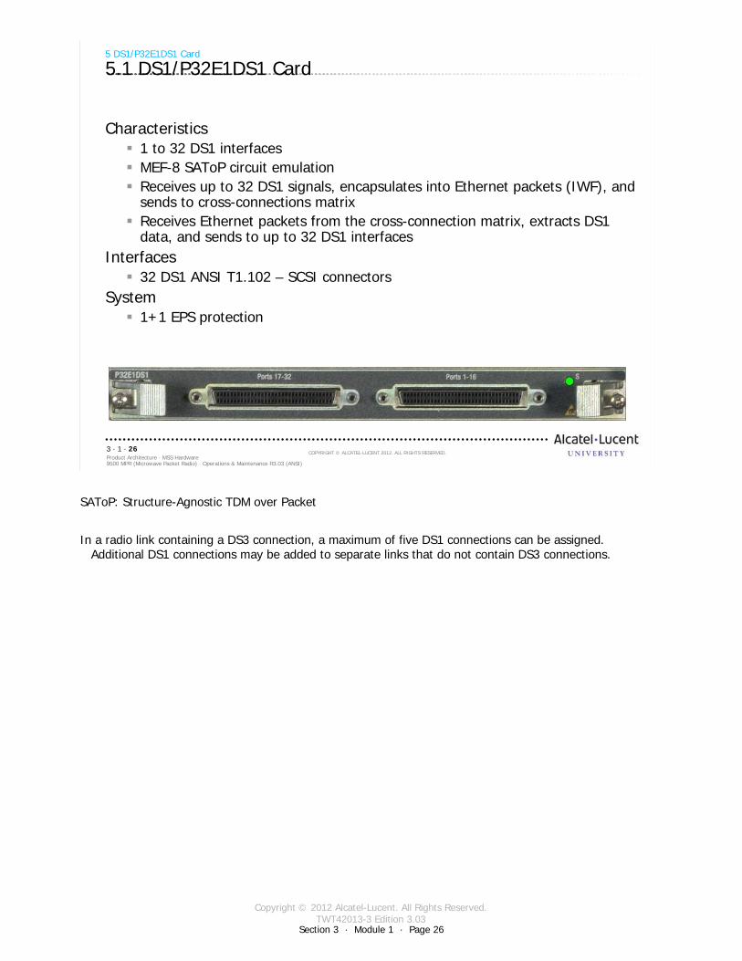
Characteristics1 to 32 DS1 interfacesMEF-8 SAToP circuit emulationReceives up to 32 DS1 signals, encapsulates into Ethernet packets (IWF), and sends to cross-connections matrixReceives Ethernet packets from the cross-connection matrix, extracts DS1 data, and sends to up to 32 DS1 interfaces
Interfaces32 DS1 ANSI T1.102 – SCSI connectors
System1+1 EPS protection
SAToP: Structure-Agnostic TDM over Packet
In a radio link containing a DS3 connection, a maximum of five DS1 connections can be assigned. Additional DS1 connections may be added to separate links that do not contain DS3 connections.
Copyright © 2012 Alcatel-Lucent. All Rights Reserved.TWT42013-3 Edition 3.03
Section 3 · Module 1 · Page 27
9500 MPR (Microwave Packet Radio) · Operations & Maintenance R3.03 (ANSI)Product Architecture · MSS Hardware3 · 1 · 27
COPYRIGHT © ALCATEL-LUCENT 2012. ALL RIGHTS RESERVED.
5 DS1/P32E1DS1 Card
5.2 DS1/P32E1DS1 Card Block Diagram
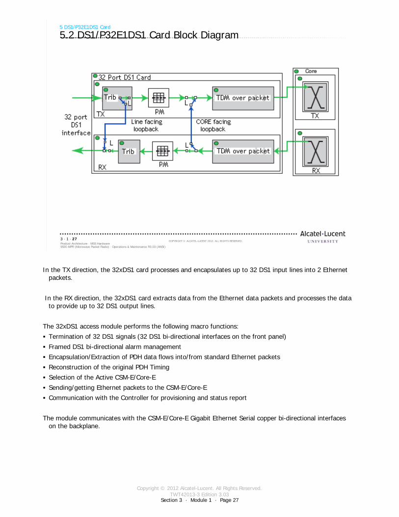
In the TX direction, the 32xDS1 card processes and encapsulates up to 32 DS1 input lines into 2 Ethernet packets.
In the RX direction, the 32xDS1 card extracts data from the Ethernet data packets and processes the data to provide up to 32 DS1 output lines.
The 32xDS1 access module performs the following macro functions:
Termination of 32 DS1 signals (32 DS1 bi-directional interfaces on the front panel)
Framed DS1 bi-directional alarm management
Encapsulation/Extraction of PDH data flows into/from standard Ethernet packets
Reconstruction of the original PDH Timing
Selection of the Active CSM-E/Core-E
Sending/getting Ethernet packets to the CSM-E/Core-E
Communication with the Controller for provisioning and status report
The module communicates with the CSM-E/Core-E Gigabit Ethernet Serial copper bi-directional interfaces on the backplane.

Copyright © 2012 Alcatel-Lucent. All Rights Reserved.TWT42013-3 Edition 3.03
Section 3 · Module 1 · Page 28
9500 MPR (Microwave Packet Radio) · Operations & Maintenance R3.03 (ANSI)Product Architecture · MSS Hardware3 · 1 · 28
COPYRIGHT © ALCATEL-LUCENT 2012. ALL RIGHTS RESERVED.
5 DS1/P32E1DS1 Card
5.3 DS1/P32E1DS1 Card Status LED
Card status LED indicates the status of the printed circuit board:Off – card not equipped, not provisioned, or not poweredBlinking green – download, booting, or flash card realignment in progressGreen – in service, normal operation, and properly provisionedYellow – in standby, properly provisioned as EPSBlinking red – card mismatchRed – card failure
Status
DS1 in/outPorts 17-32
DS1 in/outPorts 1-16
There are equipping options for the 32xDS1.
One 32xDS1 module is required in slot 5, 6, 7 or 8 for not protected configurations.
In protected radio configurations, two are required, the main module in slot 5 or 7 and the protect (spare) module in the slot directly across from the main (slot 6 or 8). The protect (spare) 32xDS1 module protects the DS1 stream if the main 32xDS1 module fails.

Copyright © 2012 Alcatel-Lucent. All Rights Reserved.TWT42013-3 Edition 3.03
9500 MPR (Microwave Packet Radio) · Operations & Maintenance R3.03 (ANSI)Product Architecture · MSS Hardware3 · 1 · 29
COPYRIGHT © ALCATEL-LUCENT 2012. ALL RIGHTS RESERVED.
6 DS3/P2E3DS3 Card
Refer to 9500 MPR Product Information, 3EM23952AHAA, UDS-106 for more details
Section 3 · Module 1 · Page 29
Copyright © 2012 Alcatel-Lucent. All Rights Reserved.TWT42013-3 Edition 3.03
Section 3 · Module 1 · Page 30
9500 MPR (Microwave Packet Radio) · Operations & Maintenance R3.03 (ANSI)Product Architecture · MSS Hardware3 · 1 · 30
COPYRIGHT © ALCATEL-LUCENT 2012. ALL RIGHTS RESERVED.
6 DS3/P2E3DS3 Card
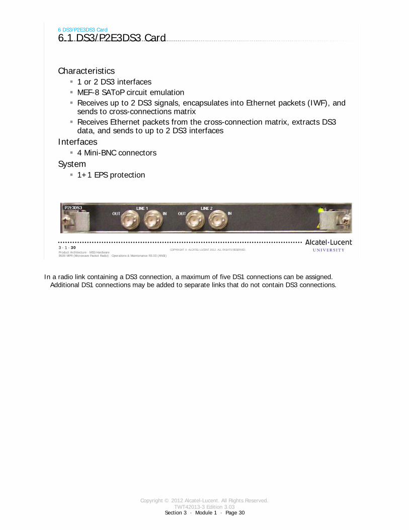
6.1 DS3/P2E3DS3 Card
Characteristics1 or 2 DS3 interfacesMEF-8 SAToP circuit emulationReceives up to 2 DS3 signals, encapsulates into Ethernet packets (IWF), and sends to cross-connections matrixReceives Ethernet packets from the cross-connection matrix, extracts DS3 data, and sends to up to 2 DS3 interfaces
Interfaces4 Mini-BNC connectors
System1+1 EPS protection
In a radio link containing a DS3 connection, a maximum of five DS1 connections can be assigned. Additional DS1 connections may be added to separate links that do not contain DS3 connections.
Copyright © 2012 Alcatel-Lucent. All Rights Reserved.TWT42013-3 Edition 3.03
Section 3 · Module 1 · Page 31
9500 MPR (Microwave Packet Radio) · Operations & Maintenance R3.03 (ANSI)Product Architecture · MSS Hardware3 · 1 · 31
COPYRIGHT © ALCATEL-LUCENT 2012. ALL RIGHTS RESERVED.
6 DS3/P2E3DS3 Card
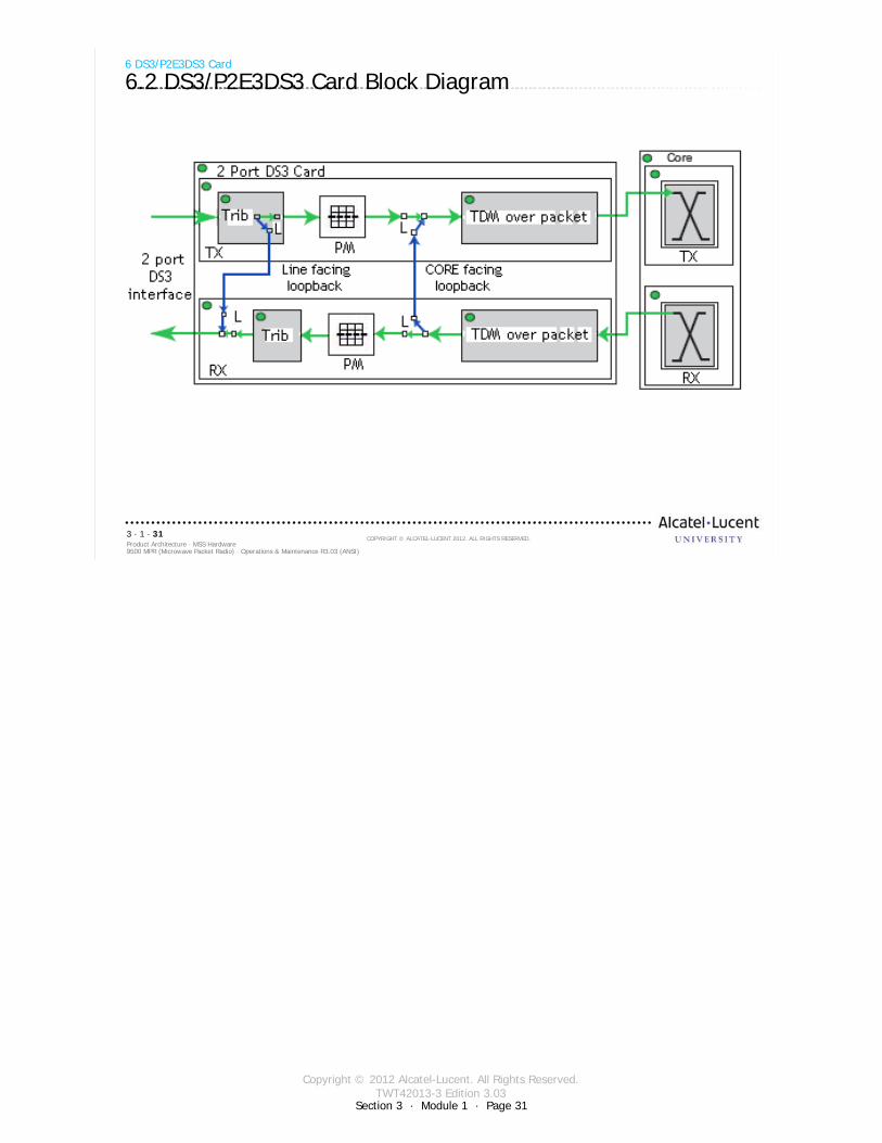
6.2 DS3/P2E3DS3 Card Block Diagram
Copyright © 2012 Alcatel-Lucent. All Rights Reserved.TWT42013-3 Edition 3.03
Section 3 · Module 1 · Page 32
9500 MPR (Microwave Packet Radio) · Operations & Maintenance R3.03 (ANSI)Product Architecture · MSS Hardware3 · 1 · 32
COPYRIGHT © ALCATEL-LUCENT 2012. ALL RIGHTS RESERVED.
6 DS3/P2E3DS3 Card
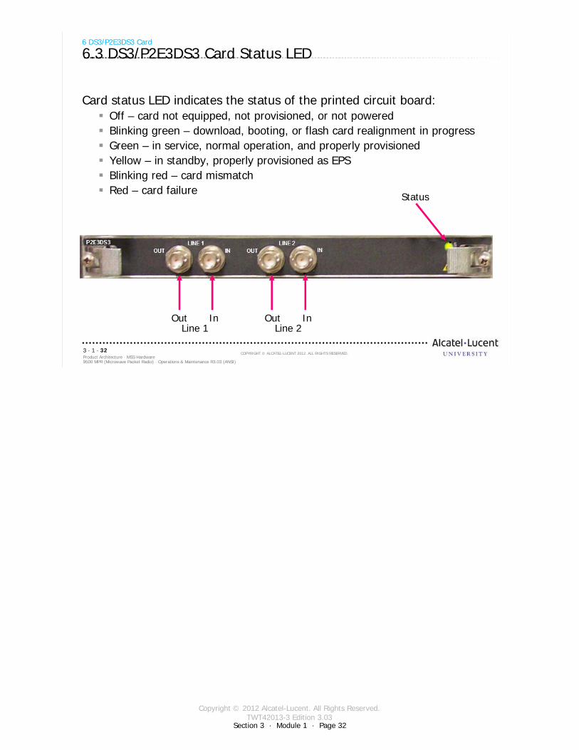
6.3 DS3/P2E3DS3 Card Status LED
Card status LED indicates the status of the printed circuit board:Off – card not equipped, not provisioned, or not poweredBlinking green – download, booting, or flash card realignment in progressGreen – in service, normal operation, and properly provisionedYellow – in standby, properly provisioned as EPSBlinking red – card mismatchRed – card failure
Status
Out InLine 1
Out InLine 2

Copyright © 2012 Alcatel-Lucent. All Rights Reserved.TWT42013-3 Edition 3.03
9500 MPR (Microwave Packet Radio) · Operations & Maintenance R3.03 (ANSI)Product Architecture · MSS Hardware3 · 1 · 33
COPYRIGHT © ALCATEL-LUCENT 2012. ALL RIGHTS RESERVED.
7 MPTACC Card
Refer to 9500 MPR Product Information, 3EM23952AHAA, UDS-118 for more details
Section 3 · Module 1 · Page 33
Copyright © 2012 Alcatel-Lucent. All Rights Reserved.TWT42013-3 Edition 3.03
Section 3 · Module 1 · Page 34
9500 MPR (Microwave Packet Radio) · Operations & Maintenance R3.03 (ANSI)Product Architecture · MSS Hardware3 · 1 · 34
COPYRIGHT © ALCATEL-LUCENT 2012. ALL RIGHTS RESERVED.
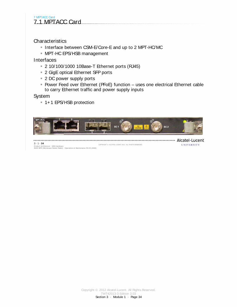
7 MPTACC Card
7.1 MPTACC Card
CharacteristicsInterface between CSM-E/Core-E and up to 2 MPT-HC/MCMPT-HC EPS/HSB management
Interfaces2 10/100/1000 10Base-T Ethernet ports (RJ45)2 GigE optical Ethernet SFP ports2 DC power supply portsPower Feed over Ethernet (PFoE) function – uses one electrical Ethernet cable to carry Ethernet traffic and power supply inputs
System1+1 EPS/HSB protection
Copyright © 2012 Alcatel-Lucent. All Rights Reserved.TWT42013-3 Edition 3.03
Section 3 · Module 1 · Page 35
9500 MPR (Microwave Packet Radio) · Operations & Maintenance R3.03 (ANSI)Product Architecture · MSS Hardware3 · 1 · 35
COPYRIGHT © ALCATEL-LUCENT 2012. ALL RIGHTS RESERVED.
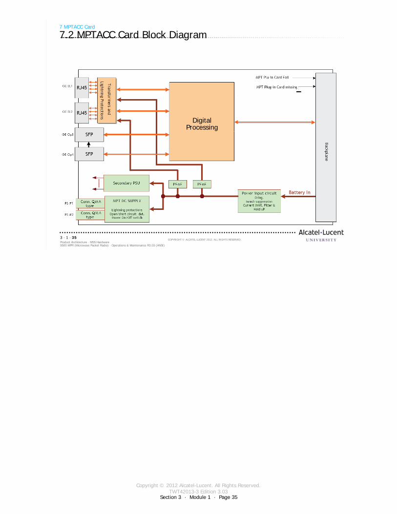
7 MPTACC Card
7.2 MPTACC Card Block Diagram
DigitalProcessing
Copyright © 2012 Alcatel-Lucent. All Rights Reserved.TWT42013-3 Edition 3.03
Section 3 · Module 1 · Page 36
9500 MPR (Microwave Packet Radio) · Operations & Maintenance R3.03 (ANSI)Product Architecture · MSS Hardware3 · 1 · 36
COPYRIGHT © ALCATEL-LUCENT 2012. ALL RIGHTS RESERVED.
7 MPTACC Card
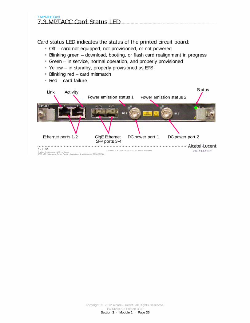
7.3 MPTACC Card Status LED
Card status LED indicates the status of the printed circuit board:Off – card not equipped, not provisioned, or not poweredBlinking green – download, booting, or flash card realignment in progressGreen – in service, normal operation, and properly provisionedYellow – in standby, properly provisioned as EPSBlinking red – card mismatchRed – card failure
Ethernet ports 1-2 GigE Ethernet SFP ports 3-4
Status
Power emission status 1 Power emission status 2
DC power port 1 DC power port 2
Link Activity

Copyright © 2012 Alcatel-Lucent. All Rights Reserved.TWT42013-3 Edition 3.03
9500 MPR (Microwave Packet Radio) · Operations & Maintenance R3.03 (ANSI)Product Architecture · MSS Hardware3 · 1 · 37
COPYRIGHT © ALCATEL-LUCENT 2012. ALL RIGHTS RESERVED.
8 MOD300 Card
Refer to 9500 MPR Product Information, 3EM23952AHAA, UDS-104 for more details
Section 3 · Module 1 · Page 37
Copyright © 2012 Alcatel-Lucent. All Rights Reserved.TWT42013-3 Edition 3.03
Section 3 · Module 1 · Page 38
9500 MPR (Microwave Packet Radio) · Operations & Maintenance R3.03 (ANSI)Product Architecture · MSS Hardware3 · 1 · 38
COPYRIGHT © ALCATEL-LUCENT 2012. ALL RIGHTS RESERVED.
8 MOD300 Card
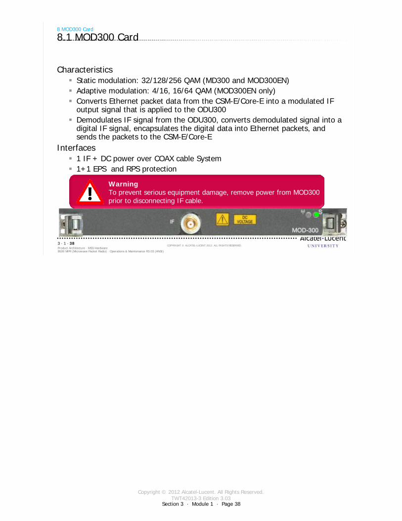
8.1 MOD300 Card
CharacteristicsStatic modulation: 32/128/256 QAM (MD300 and MOD300EN)Adaptive modulation: 4/16, 16/64 QAM (MOD300EN only)Converts Ethernet packet data from the CSM-E/Core-E into a modulated IF output signal that is applied to the ODU300Demodulates IF signal from the ODU300, converts demodulated signal into a digital IF signal, encapsulates the digital data into Ethernet packets, and sends the packets to the CSM-E/Core-E
Interfaces1 IF + DC power over COAX cable System1+1 EPS and RPS protection
Warning To prevent serious equipment damage, remove power from MOD300 prior to disconnecting IF cable.
Copyright © 2012 Alcatel-Lucent. All Rights Reserved.TWT42013-3 Edition 3.03
Section 3 · Module 1 · Page 39
9500 MPR (Microwave Packet Radio) · Operations & Maintenance R3.03 (ANSI)Product Architecture · MSS Hardware3 · 1 · 39
COPYRIGHT © ALCATEL-LUCENT 2012. ALL RIGHTS RESERVED.
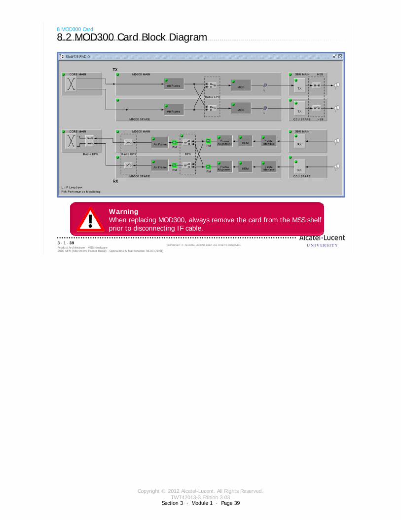
8 MOD300 Card
8.2 MOD300 Card Block Diagram
Warning When replacing MOD300, always remove the card from the MSS shelfprior to disconnecting IF cable.
Copyright © 2012 Alcatel-Lucent. All Rights Reserved.TWT42013-3 Edition 3.03
Section 3 · Module 1 · Page 40
9500 MPR (Microwave Packet Radio) · Operations & Maintenance R3.03 (ANSI)Product Architecture · MSS Hardware3 · 1 · 40
COPYRIGHT © ALCATEL-LUCENT 2012. ALL RIGHTS RESERVED.
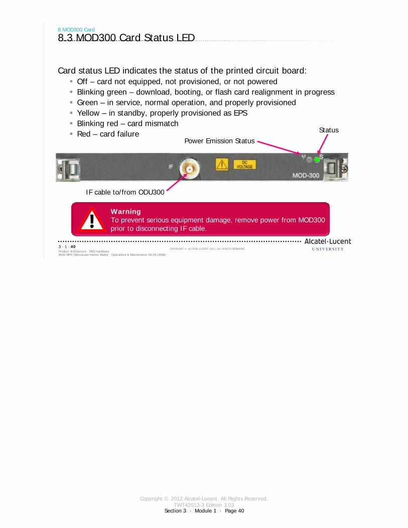
Card status LED indicates the status of the printed circuit board:Off – card not equipped, not provisioned, or not poweredBlinking green – download, booting, or flash card realignment in progressGreen – in service, normal operation, and properly provisionedYellow – in standby, properly provisioned as EPSBlinking red – card mismatchRed – card failure
8 MOD300 Card
8.3 MOD300 Card Status LED
StatusPower Emission Status
IF cable to/from ODU300
Warning To prevent serious equipment damage, remove power from MOD300 prior to disconnecting IF cable.

Copyright © 2012 Alcatel-Lucent. All Rights Reserved.TWT42013-3 Edition 3.03
9500 MPR (Microwave Packet Radio) · Operations & Maintenance R3.03 (ANSI)Product Architecture · MSS Hardware3 · 1 · 41
COPYRIGHT © ALCATEL-LUCENT 2012. ALL RIGHTS RESERVED.
9 AUX Card
Refer to 9500 MPR Product Information, 3EM23952AHAA, UDS-120 for more details
Section 3 · Module 1 · Page 41
Copyright © 2012 Alcatel-Lucent. All Rights Reserved.TWT42013-3 Edition 3.03
Section 3 · Module 1 · Page 42
9500 MPR (Microwave Packet Radio) · Operations & Maintenance R3.03 (ANSI)Product Architecture · MSS Hardware3 · 1 · 42
COPYRIGHT © ALCATEL-LUCENT 2012. ALL RIGHTS RESERVED.
9 AUX Card
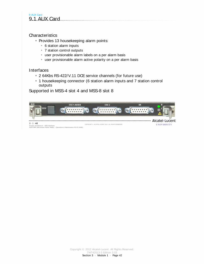
9.1 AUX Card
CharacteristicsProvides 13 housekeeping alarm points:
6 station alarm inputs7 station control outputsuser provisionable alarm labels on a per alarm basisuser provisionable alarm active polarity on a per alarm basis
Interfaces2 64Kbs RS-422/V.11 DCE service channels (for future use)1 housekeeping connector (6 station alarm inputs and 7 station control outputs
Supported in MSS-4 slot 4 and MSS-8 slot 8
Copyright © 2012 Alcatel-Lucent. All Rights Reserved.TWT42013-3 Edition 3.03
Section 3 · Module 1 · Page 43
9500 MPR (Microwave Packet Radio) · Operations & Maintenance R3.03 (ANSI)Product Architecture · MSS Hardware3 · 1 · 43
COPYRIGHT © ALCATEL-LUCENT 2012. ALL RIGHTS RESERVED.
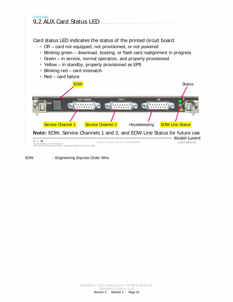
Card status LED indicates the status of the printed circuit board:Off – card not equipped, not provisioned, or not poweredBlinking green – download, booting, or flash card realignment in progressGreen – in service, normal operation, and properly provisionedYellow – in standby, properly provisioned as EPSBlinking red – card mismatchRed – card failure
Note: EOW, Service Channels 1 and 2, and EOW Line Status for future use
9 AUX Card
9.2 AUX Card Status LED
Status
EOW Line StatusService Channel 1 Service Channel 2 Housekeeping
EOW
EOW - Engineering Express Order Wire

Copyright © 2012 Alcatel-Lucent. All Rights Reserved.TWT42013-3 Edition 3.03
Section 3 · Module 1 · Page 44
9500 MPR (Microwave Packet Radio) · Operations & Maintenance R3.03 (ANSI)Product Architecture · MSS Hardware3 · 1 · 44
COPYRIGHT © ALCATEL-LUCENT 2012. ALL RIGHTS RESERVED.
Blank page
Switch to notes view!
This page intentionally left blank

Copyright © 2012 Alcatel-Lucent. All Rights Reserved.TWT42013-3 Edition 3.03
9500 MPR (Microwave Packet Radio) · Operations & Maintenance R3.03 (ANSI)Product Architecture · MSS Hardware3 · 1 · 45
COPYRIGHT © ALCATEL-LUCENT 2012. ALL RIGHTS RESERVED.
10 Fan Card
Refer to 9500 MPR Product Information, 3EM23952AHAA, UDS-110 for more details
Section 3 · Module 1 · Page 45
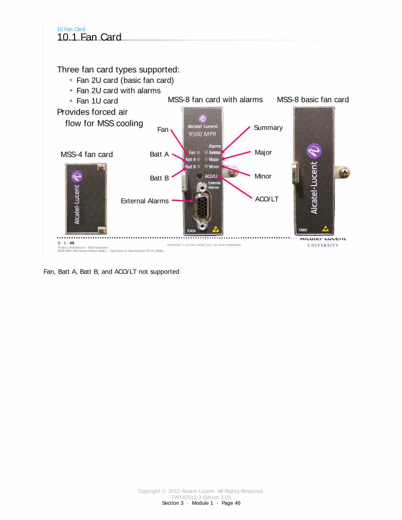
Copyright © 2012 Alcatel-Lucent. All Rights Reserved.TWT42013-3 Edition 3.03
Section 3 · Module 1 · Page 46
9500 MPR (Microwave Packet Radio) · Operations & Maintenance R3.03 (ANSI)Product Architecture · MSS Hardware3 · 1 · 46
COPYRIGHT © ALCATEL-LUCENT 2012. ALL RIGHTS RESERVED.
Three fan card types supported:Fan 2U card (basic fan card)Fan 2U card with alarmsFan 1U card
Provides forced airflow for MSS cooling
10 Fan Card
10.1 Fan Card
MSS-8 basic fan card
Fan
Batt A
Batt B
External Alarms
Summary
Major
Minor
ACO/LT
MSS-8 fan card with alarms
MSS-4 fan card
Fan, Batt A, Batt B, and ACO/LT not supported

Copyright © 2012 Alcatel-Lucent. All Rights Reserved.TWT42013-3 Edition 3.03
9500 MPR (Microwave Packet Radio) · Operations & Maintenance R3.03 (ANSI)Product Architecture · MSS Hardware3 · 1 · 47
COPYRIGHT © ALCATEL-LUCENT 2012. ALL RIGHTS RESERVED.
11 +24/-48 Volt Power Converter
Refer to 9500 MPR Product Information, 3EM23952AHAA, UDS-123 for more details
Section 3 · Module 1 · Page 47
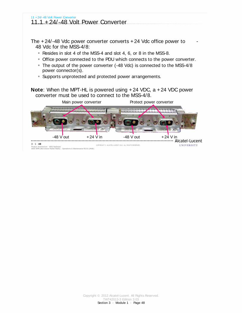
Copyright © 2012 Alcatel-Lucent. All Rights Reserved.TWT42013-3 Edition 3.03
Section 3 · Module 1 · Page 48
9500 MPR (Microwave Packet Radio) · Operations & Maintenance R3.03 (ANSI)Product Architecture · MSS Hardware3 · 1 · 48
COPYRIGHT © ALCATEL-LUCENT 2012. ALL RIGHTS RESERVED.
11 +24/-48 Volt Power Converter
11.1 +24/-48 Volt Power Converter
The +24/-48 Vdc power converter converts +24 Vdc office power to -48 Vdc for the MSS-4/8:
Resides in slot 4 of the MSS-4 and slot 4, 6, or 8 in the MSS-8. Office power connected to the PDU which connects to the power converter. The output of the power converter (-48 Vdc) is connected to the MSS-4/8 power connector(s). Supports unprotected and protected power arrangements.
Note: When the MPT-HL is powered using +24 VDC, a +24 VDC power converter must be used to connect to the MSS-4/8.
Protect power converter
+24 V in-48 V out +24 V in -48 V out
Main power converter

Copyright © 2012 Alcatel-Lucent. All Rights Reserved.TWT42013-3 Edition 3.03
9500 MPR (Microwave Packet Radio) · Operations & Maintenance R3.03 (ANSI)Product Architecture · MSS Hardware3 · 1 · 49
COPYRIGHT © ALCATEL-LUCENT 2012. ALL RIGHTS RESERVED.
12 Power Injector
Refer to 9500 MPR Product Information, 3EM23952AHAA, UDS-122 for more details
Section 3 · Module 1 · Page 49
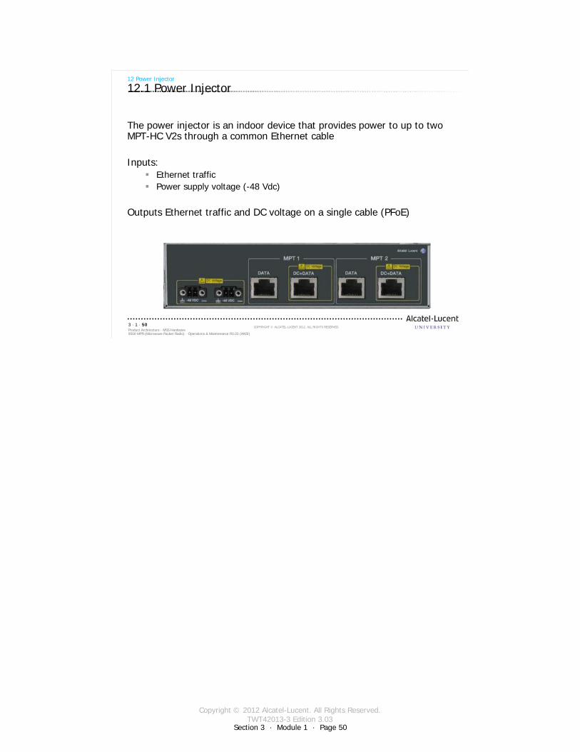
Copyright © 2012 Alcatel-Lucent. All Rights Reserved.TWT42013-3 Edition 3.03
9500 MPR (Microwave Packet Radio) · Operations & Maintenance R3.03 (ANSI)Product Architecture · MSS Hardware3 · 1 · 50
COPYRIGHT © ALCATEL-LUCENT 2012. ALL RIGHTS RESERVED.
12 Power Injector
12.1 Power Injector
The power injector is an indoor device that provides power to up to two MPT-HC V2s through a common Ethernet cable
Inputs:Ethernet trafficPower supply voltage (-48 Vdc)
Outputs Ethernet traffic and DC voltage on a single cable (PFoE)
Section 3 · Module 1 · Page 50

Copyright © 2012 Alcatel-Lucent. All Rights Reserved.TWT42013-3 Edition 3.03
9500 MPR (Microwave Packet Radio) · Operations & Maintenance R3.03 (ANSI)Product Architecture · MSS Hardware3 · 1 · 51
COPYRIGHT © ALCATEL-LUCENT 2012. ALL RIGHTS RESERVED.
13 Microwave Service Switch (MSS-1c)
Refer to 9500 MPR-A MSS-1c User Manual, 3EM24571ABAA for more details
Section 3 · Module 1 · Page 51
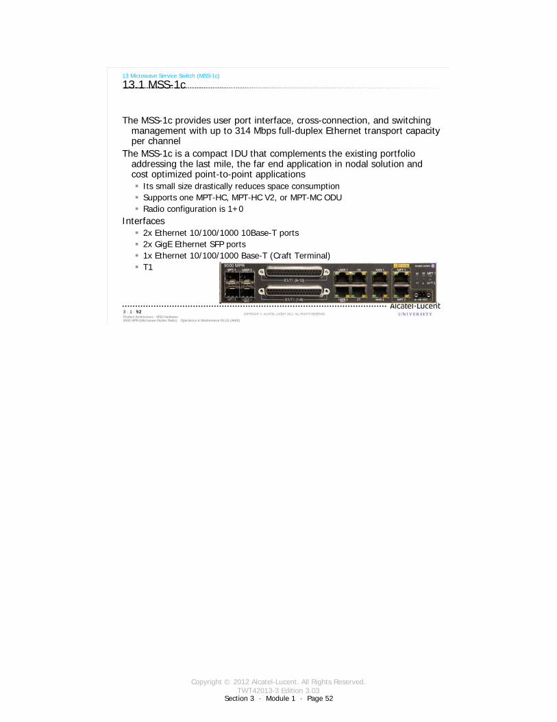
Copyright © 2012 Alcatel-Lucent. All Rights Reserved.TWT42013-3 Edition 3.03
Section 3 · Module 1 · Page 52
9500 MPR (Microwave Packet Radio) · Operations & Maintenance R3.03 (ANSI)Product Architecture · MSS Hardware3 · 1 · 52
COPYRIGHT © ALCATEL-LUCENT 2012. ALL RIGHTS RESERVED.
13 Microwave Service Switch (MSS-1c)
13.1 MSS-1c
The MSS-1c provides user port interface, cross-connection, and switching management with up to 314 Mbps full-duplex Ethernet transport capacity per channel
The MSS-1c is a compact IDU that complements the existing portfolio addressing the last mile, the far end application in nodal solution and cost optimized point-to-point applications
Its small size drastically reduces space consumptionSupports one MPT-HC, MPT-HC V2, or MPT-MC ODURadio configuration is 1+0
Interfaces2x Ethernet 10/100/1000 10Base-T ports 2x GigE Ethernet SFP ports1x Ethernet 10/100/1000 Base-T (Craft Terminal)T1
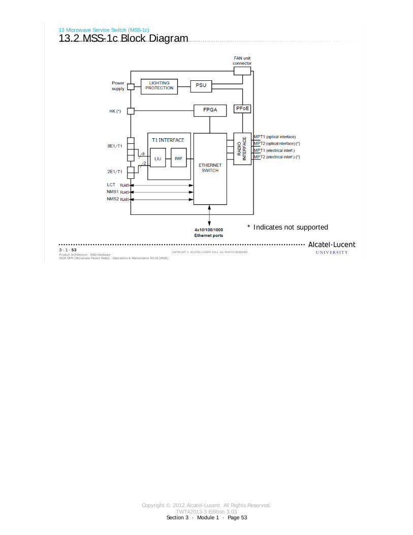
Copyright © 2012 Alcatel-Lucent. All Rights Reserved.TWT42013-3 Edition 3.03
Section 3 · Module 1 · Page 53
9500 MPR (Microwave Packet Radio) · Operations & Maintenance R3.03 (ANSI)Product Architecture · MSS Hardware3 · 1 · 53
COPYRIGHT © ALCATEL-LUCENT 2012. ALL RIGHTS RESERVED.
13 Microwave Service Switch (MSS-1c)
13.2 MSS-1c Block Diagram
* Indicates not supported
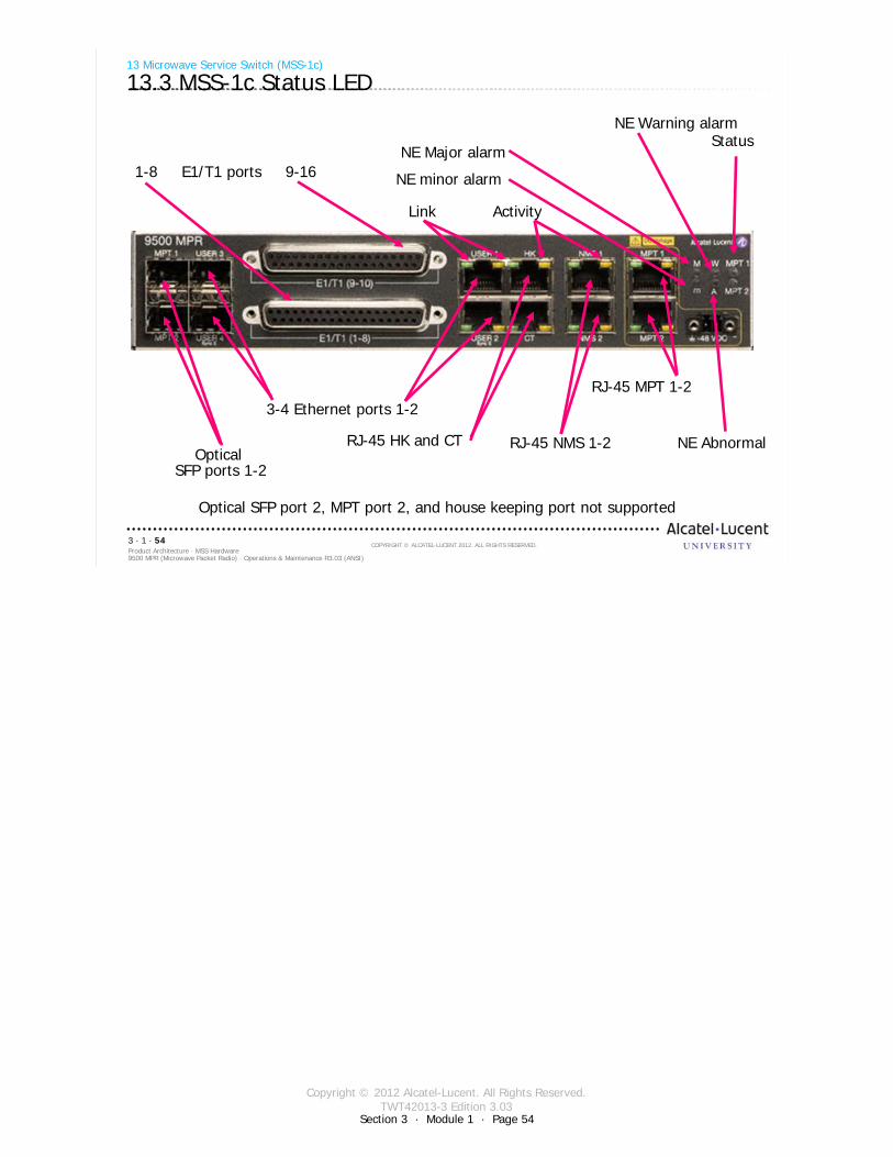
Copyright © 2012 Alcatel-Lucent. All Rights Reserved.TWT42013-3 Edition 3.03
Section 3 · Module 1 · Page 54
9500 MPR (Microwave Packet Radio) · Operations & Maintenance R3.03 (ANSI)Product Architecture · MSS Hardware3 · 1 · 54
COPYRIGHT © ALCATEL-LUCENT 2012. ALL RIGHTS RESERVED.
13 Microwave Service Switch (MSS-1c)
13.3 MSS-1c Status LED
3-4 Ethernet ports 1-2
RJ-45 NMS 1-2Optical
SFP ports 1-2
RJ-45 MPT 1-2
RJ-45 HK and CT
Link Activity
1-8 E1/T1 ports 9-16
Optical SFP port 2, MPT port 2, and house keeping port not supported
StatusNE Warning alarm
NE Major alarm
NE minor alarm
NE Abnormal

Copyright © 2012 Alcatel-Lucent. All Rights Reserved.TWT42013-3 Edition 3.03
9500 MPR (Microwave Packet Radio) · Operations & Maintenance R3.03 (ANSI)Product Architecture · MSS Hardware3 · 1 · 55
COPYRIGHT © ALCATEL-LUCENT 2012. ALL RIGHTS RESERVED.
14 Patch Panels
Refer to 9500 MPR Product Information, 3EM23952AHAA, UDS-114 and 115 for more details
Section 3 · Module 1 · Page 55
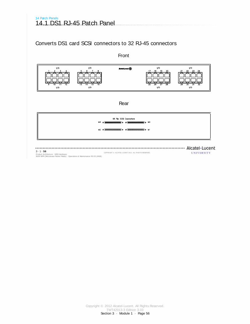
Copyright © 2012 Alcatel-Lucent. All Rights Reserved.TWT42013-3 Edition 3.03
Section 3 · Module 1 · Page 56
9500 MPR (Microwave Packet Radio) · Operations & Maintenance R3.03 (ANSI)Product Architecture · MSS Hardware3 · 1 · 56
COPYRIGHT © ALCATEL-LUCENT 2012. ALL RIGHTS RESERVED.
Front
Rear
14 Patch Panels
14.1 DS1 RJ-45 Patch Panel
Converts DS1 card SCSI connectors to 32 RJ-45 connectors
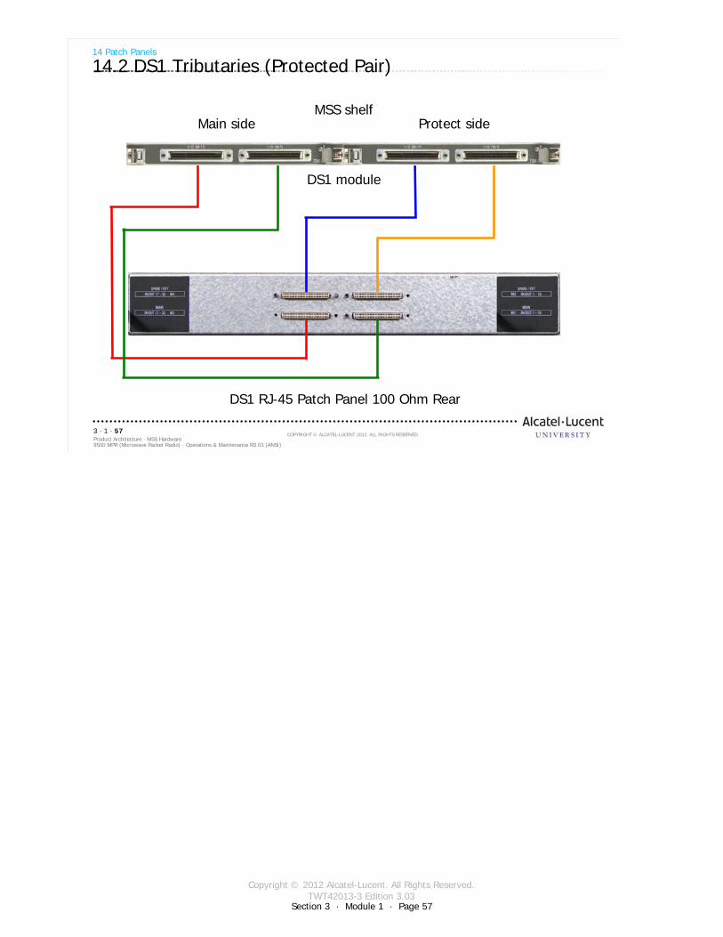
Copyright © 2012 Alcatel-Lucent. All Rights Reserved.TWT42013-3 Edition 3.03
Section 3 · Module 1 · Page 57
9500 MPR (Microwave Packet Radio) · Operations & Maintenance R3.03 (ANSI)Product Architecture · MSS Hardware3 · 1 · 57
COPYRIGHT © ALCATEL-LUCENT 2012. ALL RIGHTS RESERVED.
14 Patch Panels
14.2 DS1 Tributaries (Protected Pair)
DS1 module
MSS shelfMain side Protect side
DS1 RJ-45 Patch Panel 100 Ohm Rear

Copyright © 2012 Alcatel-Lucent. All Rights Reserved.TWT42013-3 Edition 3.03
Section 3 · Module 1 · Page 58
9500 MPR (Microwave Packet Radio) · Operations & Maintenance R3.03 (ANSI)Product Architecture · MSS Hardware3 · 1 · 58
COPYRIGHT © ALCATEL-LUCENT 2012. ALL RIGHTS RESERVED.
14 Patch Panels
14.3 DS1 D-Connector Patch Panel
Converts DS1 card SCSI connectors to 4 37-position DSUB connectorsFront
Rear
Copyright © 2012 Alcatel-Lucent. All Rights Reserved.TWT42013-3 Edition 3.03
Section 3 · Module 1 · Page 59
9500 MPR (Microwave Packet Radio) · Operations & Maintenance R3.03 (ANSI)Product Architecture · MSS Hardware3 · 1 · 59
COPYRIGHT © ALCATEL-LUCENT 2012. ALL RIGHTS RESERVED.
Module summary
Cards of the MSS-4 and -8:CSM-E/Core-EP8ETH/EASDS1/P32E1DS1DS3/P2E3DS3MPTACCMOD300AUXFan
+24/-48 Power ConverterPower InjectorMSS-1cPatch panels (Distributors)
Copyright © 2012 Alcatel-Lucent. All Rights Reserved.TWT42013-3 Edition 3.03
Section 3 · Module 1 · Page 60
9500 MPR (Microwave Packet Radio) · Operations & Maintenance R3.03 (ANSI)Product Architecture · MSS Hardware3 · 1 · 60
COPYRIGHT © ALCATEL-LUCENT 2012. ALL RIGHTS RESERVED.
End of moduleMSS Hardware

Copyright © 2012 Alcatel-Lucent. All Rights Reserved.TWT42013-4 Edition 3.03
Section 3 · Module 2 · Page 1
Do not delete this graphic elements in here:
All Rights Reserved © Alcatel-Lucent @@YEAR
Module 2MPT HardwareTWT42013-4 Edition 3.03
Section 3Product Architecture
9500 MPR (Microwave Packet Radio)Operations & Maintenance R3.03 (ANSI)
TWT42013 Edition 1.1
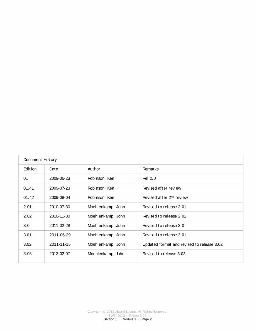
Copyright © 2012 Alcatel-Lucent. All Rights Reserved.TWT42013-4 Edition 3.03
Section 3 · Module 2 · Page 2
9500 MPR (Microwave Packet Radio) · Operations & Maintenance R3.03 (ANSI)Product Architecture · MPT Hardware3 · 2 · 2
COPYRIGHT © ALCATEL-LUCENT 2012. ALL RIGHTS RESERVED.
Blank page
This page is left blank intentionally
Document History
Edition Date Author Remarks
01 2009-06-23 Robinson, Ken Rel 2.0
01.41 2009-07-23 Robinson, Ken Revised after review
01.42 2009-08-04 Robinson, Ken Revised after 2nd review
2.01 2010-07-30 Moehlenkamp, John Revised to release 2.01
2.02 2010-11-30 Moehlenkamp, John Revised to release 2.02
3.0 2011-02-28 Moehlenkamp, John Revised to release 3.0
3.01 2011-06-29 Moehlenkamp, John Revised to release 3.01
3.02 2011-11-15 Moehlenkamp, John Updated format and revised to release 3.02
3.03 2012-02-07 Moehlenkamp, John Revised to release 3.03
Copyright © 2012 Alcatel-Lucent. All Rights Reserved.TWT42013-4 Edition 3.03
Section 3 · Module 2 · Page 3
9500 MPR (Microwave Packet Radio) · Operations & Maintenance R3.03 (ANSI)Product Architecture · MPT Hardware3 · 2 · 3
COPYRIGHT © ALCATEL-LUCENT 2012. ALL RIGHTS RESERVED.
Module objectives
Upon completion of this module, you should be able to:
Describe the functionality of the Microwave Packet Transport – High Capacity, Long Haul (MPT-HL)
Radio TransceiverMPT-HL to RFMPT-HL from MSS
Radio Configuration and Switching1+0 unprotected1+1 Hot Standby (HSB)Hot Standby Space Diversity (HSSD)Frequency DiversityMPT-HL Characteristics

Copyright © 2012 Alcatel-Lucent. All Rights Reserved.TWT42013-4 Edition 3.03
Section 3 · Module 2 · Page 4
9500 MPR (Microwave Packet Radio) · Operations & Maintenance R3.03 (ANSI)Product Architecture · MPT Hardware3 · 2 · 4
COPYRIGHT © ALCATEL-LUCENT 2012. ALL RIGHTS RESERVED.
Module objectives [cont.]
This page is left blank intentionally

Copyright © 2012 Alcatel-Lucent. All Rights Reserved.TWT42013-4 Edition 3.03
9500 MPR (Microwave Packet Radio) · Operations & Maintenance R3.03 (ANSI)Product Architecture · MPT Hardware3 · 2 · 5
COPYRIGHT © ALCATEL-LUCENT 2012. ALL RIGHTS RESERVED.
Table of Contents
Switch to notes view! Page
1 Microwave Packet Transport-Long Haul (MPT-HL) 71.1 MPT-HL Overview 81.2 Radio Transceiver Cards 91.3 MPT-HL to RF 101.4 Interface to the MPT-HL from MSS-8 11
2 MPT-HL Transceiver 132.1 MPT-HL Transceiver 142.2 MPT-HL Transceiver Status LED 152.3 MPT-HL Transceiver LEDs 16
3 Radio Configuration and Switching 173.1 MPT-HL 183.2 1+0 unprotected 193.3 1+1 Hot Standby (HSB) 203.4 Hot Standby 223.5 Hot Standby Space Diversity (HSSD) 233.6 Space Diversity 243.7 1+1 Frequency Diversity 25
4 All Indoor Mount Configurations 274.1 All Indoor Mount - 1+0 Drop and Insert Repeater 284.2 All Indoor Mount - 1+0 4-Way Junction 294.3 All Indoor Mount - 1+1 HSB Drop and Insert Repeater 304.4 All Indoor Mount - 1+1 HSB 4-Way Junction 31
5 Characteristics 335.1 TDM Circuit Service Profile example 34

Copyright © 2012 Alcatel-Lucent. All Rights Reserved.TWT42013-4 Edition 3.03
9500 MPR (Microwave Packet Radio) · Operations & Maintenance R3.03 (ANSI)Product Architecture · MPT Hardware3 · 2 · 6
COPYRIGHT © ALCATEL-LUCENT 2012. ALL RIGHTS RESERVED.
Table of Contents [cont.]
Switch to notes view!
This page is left blank intentionally
Copyright © 2012 Alcatel-Lucent. All Rights Reserved.TWT42013-4 Edition 3.03
Section 3 · Module 2 · Page 7
9500 MPR (Microwave Packet Radio) · Operations & Maintenance R3.03 (ANSI)Product Architecture · MPT Hardware3 · 2 · 7
COPYRIGHT © ALCATEL-LUCENT 2012. ALL RIGHTS RESERVED.
1 Microwave Packet Transport-Long Haul (MPT-HL)
Refer to 9500 MPR Product Information, 3EM23952AHAA, UDS-102 for more details
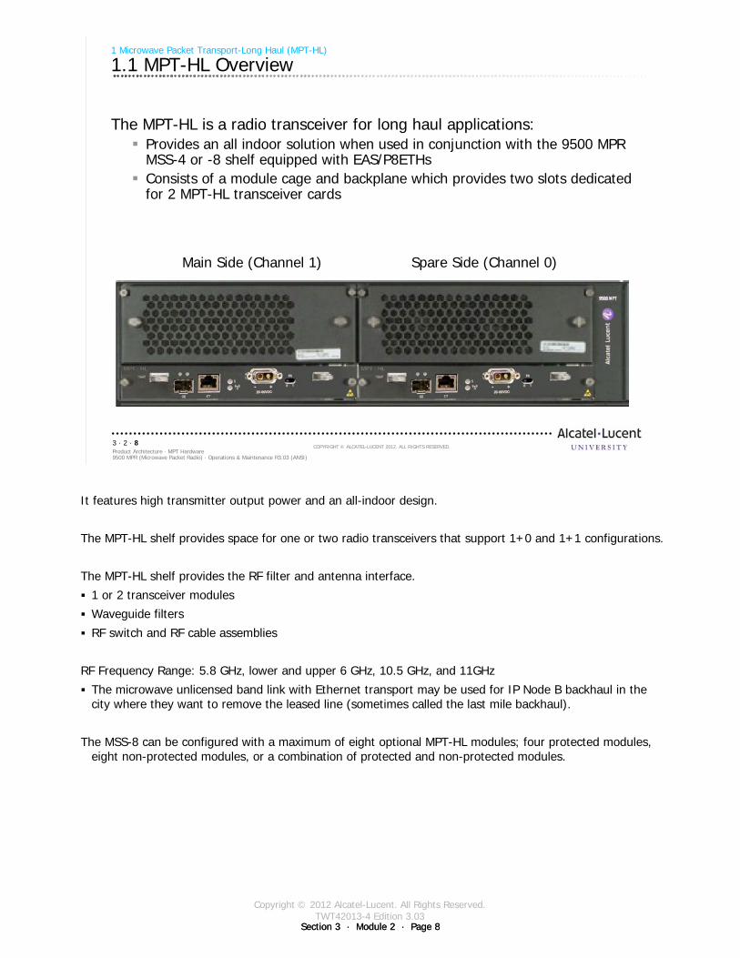
Copyright © 2012 Alcatel-Lucent. All Rights Reserved.TWT42013-4 Edition 3.03
Section 3 · Module 2 · Page 8Section 3 · Module 2 · Page 8
9500 MPR (Microwave Packet Radio) · Operations & Maintenance R3.03 (ANSI)Product Architecture · MPT Hardware3 · 2 · 8
COPYRIGHT © ALCATEL-LUCENT 2012. ALL RIGHTS RESERVED.
1 Microwave Packet Transport-Long Haul (MPT-HL)
1.1 MPT-HL Overview
The MPT-HL is a radio transceiver for long haul applications:Provides an all indoor solution when used in conjunction with the 9500 MPR MSS-4 or -8 shelf equipped with EAS/P8ETHsConsists of a module cage and backplane which provides two slots dedicated for 2 MPT-HL transceiver cards
Main Side (Channel 1) Spare Side (Channel 0)
It features high transmitter output power and an all-indoor design.
The MPT-HL shelf provides space for one or two radio transceivers that support 1+0 and 1+1 configurations.
The MPT-HL shelf provides the RF filter and antenna interface.
1 or 2 transceiver modules
Waveguide filters
RF switch and RF cable assemblies
RF Frequency Range: 5.8 GHz, lower and upper 6 GHz, 10.5 GHz, and 11GHz
The microwave unlicensed band link with Ethernet transport may be used for IP Node B backhaul in the city where they want to remove the leased line (sometimes called the last mile backhaul).
The MSS-8 can be configured with a maximum of eight optional MPT-HL modules; four protected modules, eight non-protected modules, or a combination of protected and non-protected modules.
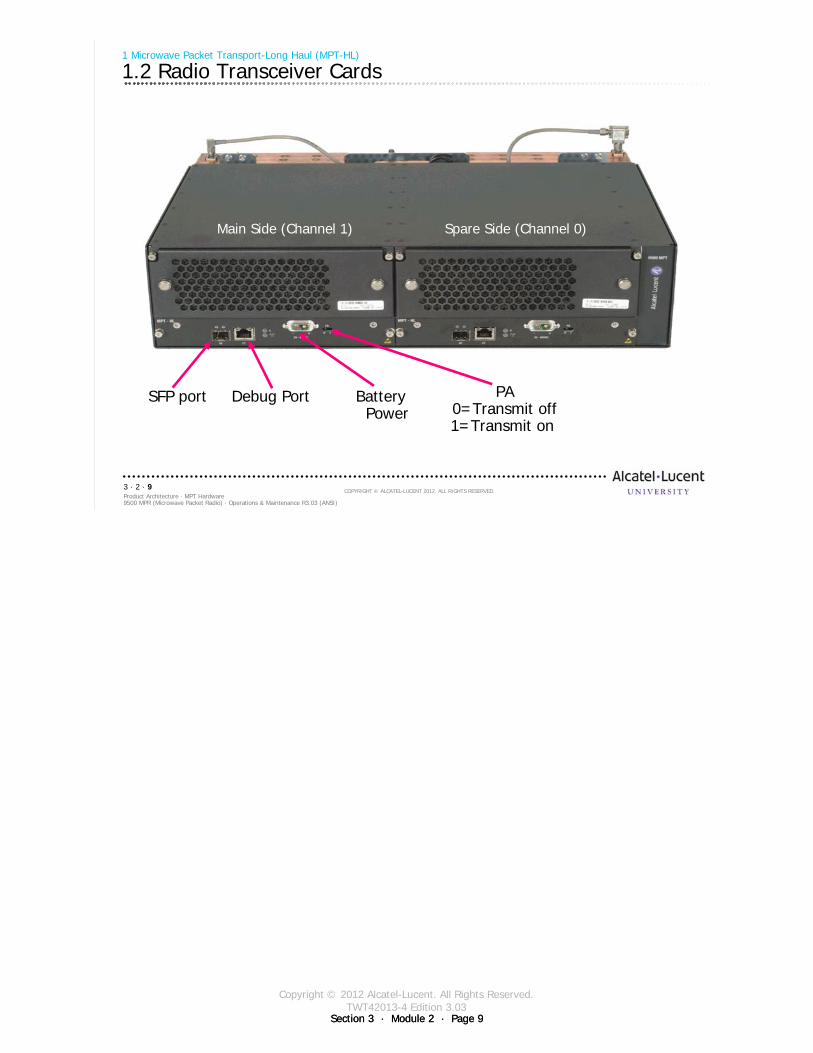
Copyright © 2012 Alcatel-Lucent. All Rights Reserved.TWT42013-4 Edition 3.03
Section 3 · Module 2 · Page 9Section 3 · Module 2 · Page 9
9500 MPR (Microwave Packet Radio) · Operations & Maintenance R3.03 (ANSI)Product Architecture · MPT Hardware3 · 2 · 9
COPYRIGHT © ALCATEL-LUCENT 2012. ALL RIGHTS RESERVED.
1 Microwave Packet Transport-Long Haul (MPT-HL)
1.2 Radio Transceiver Cards
Main Side (Channel 1) Spare Side (Channel 0)
SFP port Debug Port Battery Power
PA0=Transmit off1=Transmit on
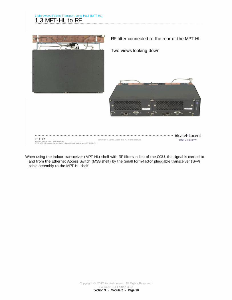
Copyright © 2012 Alcatel-Lucent. All Rights Reserved.TWT42013-4 Edition 3.03
Section 3 · Module 2 · Page 10Section 3 · Module 2 · Page 10
9500 MPR (Microwave Packet Radio) · Operations & Maintenance R3.03 (ANSI)Product Architecture · MPT Hardware3 · 2 · 10
COPYRIGHT © ALCATEL-LUCENT 2012. ALL RIGHTS RESERVED.
1 Microwave Packet Transport-Long Haul (MPT-HL)
1.3 MPT-HL to RF
RF filter connected to the rear of the MPT-HL
Two views looking down
When using the indoor transceiver (MPT-HL) shelf with RF filters in lieu of the ODU, the signal is carried to and from the Ethernet Access Switch (MSS shelf) by the Small form-factor pluggable transceiver (SFP) cable assembly to the MPT-HL shelf.

Copyright © 2012 Alcatel-Lucent. All Rights Reserved.TWT42013-4 Edition 3.03
Section 3 · Module 2 · Page 11Section 3 · Module 2 · Page 11
9500 MPR (Microwave Packet Radio) · Operations & Maintenance R3.03 (ANSI)Product Architecture · MPT Hardware3 · 2 · 11
COPYRIGHT © ALCATEL-LUCENT 2012. ALL RIGHTS RESERVED.
1 Microwave Packet Transport-Long Haul (MPT-HL)
1.4 Interface to the MPT-HL from MSS-8
MPT-HLMPT-HL
CSM-E/Core-E
EAS/P8ETH
MSS-8
EAS/P8ETH
GigE
SFP
GigE
SFP
MPT-HL
The MPT-HL is a radio transceiver for long haul applications.
MPT-HL features high transmitter output power and an all-indoor design, which is a traditional requirement.
The interface to the MPT-HL is a Gigabit Ethernet (GigE) connection, which when connected to the MSS-8, supports both traditional TDM and IP microwave solutions.
Supports the 5.8 GHz unlicensed band, lower and upper 6 GHz licensed bands, 10.5 GHz band, and 11 GHz band.
The MPT-HL facilitates replacement of existing long haul systems and a convenient migration to IP.
The interface to the MPT-HL is a Gigabit Ethernet (GigE) connection, which when connected to the MSS-8, supports both traditional TDM and IP microwave solutions.
The MPT-HL is enabled automatically when the associated MSS-8 EAS/P8ETH module is enabled.

Copyright © 2012 Alcatel-Lucent. All Rights Reserved.TWT42013-4 Edition 3.03
Section 3 · Module 2 · Page 12Section 3 · Module 2 · Page 12
9500 MPR (Microwave Packet Radio) · Operations & Maintenance R3.03 (ANSI)Product Architecture · MPT Hardware3 · 2 · 12
COPYRIGHT © ALCATEL-LUCENT 2012. ALL RIGHTS RESERVED.
Blank page
Switch to notes view!
This page intentionally left blank

Copyright © 2012 Alcatel-Lucent. All Rights Reserved.TWT42013-4 Edition 3.03
Section 3 · Module 2 · Page 13Section 3 · Module 2 · Page 13
9500 MPR (Microwave Packet Radio) · Operations & Maintenance R3.03 (ANSI)Product Architecture · MPT Hardware3 · 2 · 13
COPYRIGHT © ALCATEL-LUCENT 2012. ALL RIGHTS RESERVED.
2 MPT-HL Transceiver
Refer to 9500 MPR Product Information, 3EM23952AHAA, UDS-109 for more details
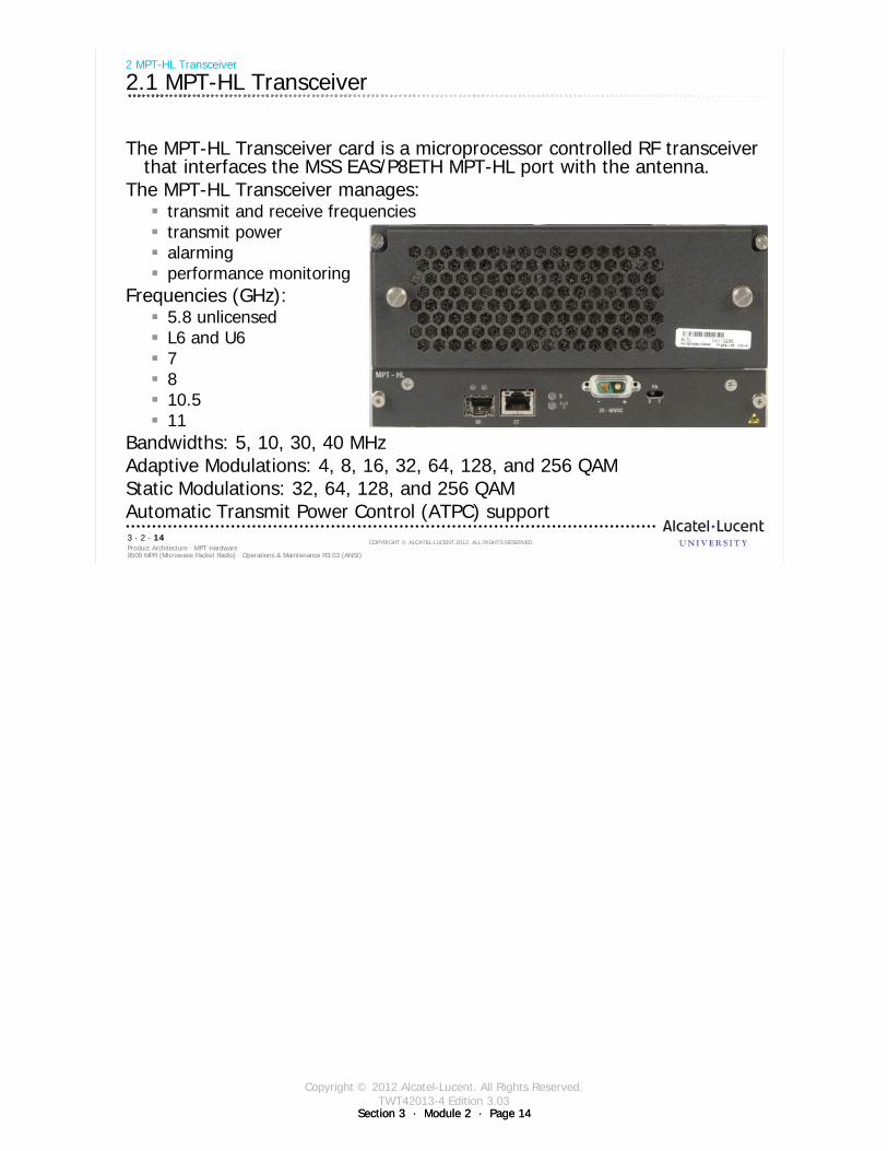
Copyright © 2012 Alcatel-Lucent. All Rights Reserved.TWT42013-4 Edition 3.03
Section 3 · Module 2 · Page 14Section 3 · Module 2 · Page 14
9500 MPR (Microwave Packet Radio) · Operations & Maintenance R3.03 (ANSI)Product Architecture · MPT Hardware3 · 2 · 14
COPYRIGHT © ALCATEL-LUCENT 2012. ALL RIGHTS RESERVED.
2 MPT-HL Transceiver
2.1 MPT-HL Transceiver
The MPT-HL Transceiver card is a microprocessor controlled RF transceiver that interfaces the MSS EAS/P8ETH MPT-HL port with the antenna.
The MPT-HL Transceiver manages:transmit and receive frequenciestransmit poweralarmingperformance monitoring
Frequencies (GHz): 5.8 unlicensedL6 and U67810.511
Bandwidths: 5, 10, 30, 40 MHzAdaptive Modulations: 4, 8, 16, 32, 64, 128, and 256 QAMStatic Modulations: 32, 64, 128, and 256 QAMAutomatic Transmit Power Control (ATPC) support
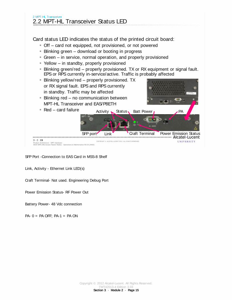
Copyright © 2012 Alcatel-Lucent. All Rights Reserved.TWT42013-4 Edition 3.03
Section 3 · Module 2 · Page 15Section 3 · Module 2 · Page 15
9500 MPR (Microwave Packet Radio) · Operations & Maintenance R3.03 (ANSI)Product Architecture · MPT Hardware3 · 2 · 15
COPYRIGHT © ALCATEL-LUCENT 2012. ALL RIGHTS RESERVED.
2 MPT-HL Transceiver
2.2 MPT-HL Transceiver Status LED
Card status LED indicates the status of the printed circuit board:Off – card not equipped, not provisioned, or not poweredBlinking green – download or booting in progressGreen – in service, normal operation, and properly provisionedYellow – in standby, properly provisionedBlinking green/red – properly provisioned. TX or RX equipment or signal fault. EPS or RPS currently in-service/active. Traffic is probably affectedBlinking yellow/red – properly provisioned. TX or RX signal fault. EPS and RPS currently in standby. Traffic may be affectedBlinking red – no communication between MPT-HL Transceiver and EAS/P8ETHRed – card failure Status
Link Power Emission Status
PABatt PowerActivity
Craft TerminalSFP port
SFP Port -Connection to EAS Card in MSS-8 Shelf
Link, Activity - Ethernet Link LED(s)
Craft Terminal- Not used. Engineering Debug Port
Power Emission Status- RF Power Out
Battery Power- 48 Vdc connection
PA- 0 = PA OFF; PA-1 = PA ON
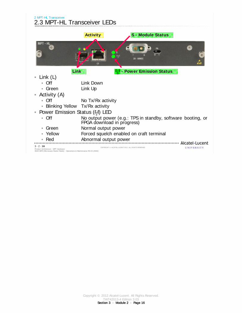
Copyright © 2012 Alcatel-Lucent. All Rights Reserved.TWT42013-4 Edition 3.03
Section 3 · Module 2 · Page 16Section 3 · Module 2 · Page 16
9500 MPR (Microwave Packet Radio) · Operations & Maintenance R3.03 (ANSI)Product Architecture · MPT Hardware3 · 2 · 16
COPYRIGHT © ALCATEL-LUCENT 2012. ALL RIGHTS RESERVED.
2 MPT-HL Transceiver
2.3 MPT-HL Transceiver LEDs
Link (L) Off Link DownGreen Link Up
Activity (A) Off No Tx/Rx activityBlinking Yellow Tx/Rx activity
Power Emission Status (M) LEDOff No output power (e.g.: TPS in standby, software booting, or
FPGA download in progress)Green Normal output powerYellow Forced squelch enabled on craft terminal Red Abnormal output power
Activity
Link
S - Module Status
- Power Emission Status

Copyright © 2012 Alcatel-Lucent. All Rights Reserved.TWT42013-4 Edition 3.03
Section 3 · Module 2 · Page 17Section 3 · Module 2 · Page 17
9500 MPR (Microwave Packet Radio) · Operations & Maintenance R3.03 (ANSI)Product Architecture · MPT Hardware3 · 2 · 17
COPYRIGHT © ALCATEL-LUCENT 2012. ALL RIGHTS RESERVED.
3 Radio Configuration and Switching
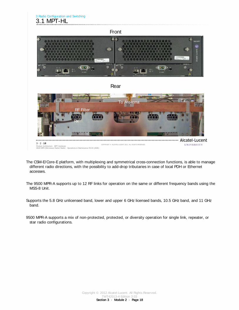
Copyright © 2012 Alcatel-Lucent. All Rights Reserved.TWT42013-4 Edition 3.03
Section 3 · Module 2 · Page 18Section 3 · Module 2 · Page 18
9500 MPR (Microwave Packet Radio) · Operations & Maintenance R3.03 (ANSI)Product Architecture · MPT Hardware3 · 2 · 18
COPYRIGHT © ALCATEL-LUCENT 2012. ALL RIGHTS RESERVED.
3 Radio Configuration and Switching
3.1 MPT-HL
Rx
Tx
RF Filter
To Antenna
Front
Rear
The CSM-E/Core-E platform, with multiplexing and symmetrical cross-connection functions, is able to manage different radio directions, with the possibility to add-drop tributaries in case of local PDH or Ethernet accesses.
The 9500 MPR-A supports up to 12 RF links for operation on the same or different frequency bands using the MSS-8 Unit.
Supports the 5.8 GHz unlicensed band, lower and upper 6 GHz licensed bands, 10.5 GHz band, and 11 GHz band.
9500 MPR-A supports a mix of non-protected, protected, or diversity operation for single link, repeater, or star radio configurations.
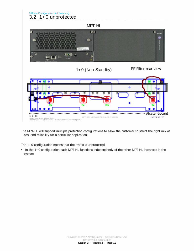
Copyright © 2012 Alcatel-Lucent. All Rights Reserved.TWT42013-4 Edition 3.03
Section 3 · Module 2 · Page 19Section 3 · Module 2 · Page 19
9500 MPR (Microwave Packet Radio) · Operations & Maintenance R3.03 (ANSI)Product Architecture · MPT Hardware3 · 2 · 19
COPYRIGHT © ALCATEL-LUCENT 2012. ALL RIGHTS RESERVED.
3 Radio Configuration and Switching
3.2 1+0 unprotected
MPT-HL
RF Filter rear view1+0 (Non-Standby)
The MPT-HL will support multiple protection configurations to allow the customer to select the right mix of cost and reliability for a particular application.
The 1+0 configuration means that the traffic is unprotected.
In the 1+0 configuration each MPT-HL functions independently of the other MPT-HL instances in the system.
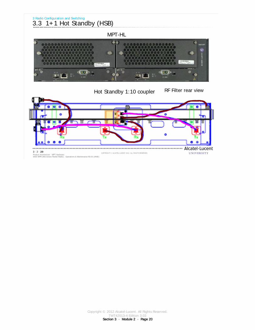
Copyright © 2012 Alcatel-Lucent. All Rights Reserved.TWT42013-4 Edition 3.03
Section 3 · Module 2 · Page 20Section 3 · Module 2 · Page 20
9500 MPR (Microwave Packet Radio) · Operations & Maintenance R3.03 (ANSI)Product Architecture · MPT Hardware3 · 2 · 20
COPYRIGHT © ALCATEL-LUCENT 2012. ALL RIGHTS RESERVED.
3 Radio Configuration and Switching
3.3 1+1 Hot Standby (HSB)
MPT-HL
RF Filter rear viewHot Standby 1:10 coupler
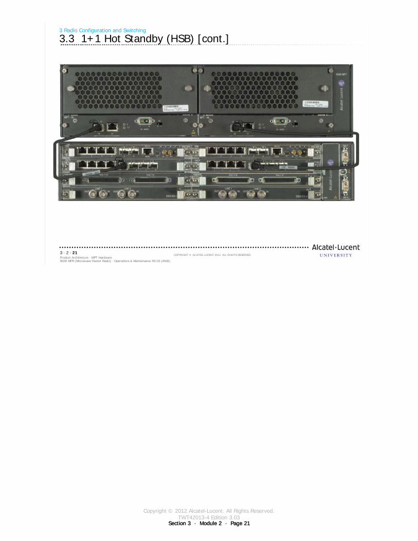
Copyright © 2012 Alcatel-Lucent. All Rights Reserved.TWT42013-4 Edition 3.03
Section 3 · Module 2 · Page 21Section 3 · Module 2 · Page 21
9500 MPR (Microwave Packet Radio) · Operations & Maintenance R3.03 (ANSI)Product Architecture · MPT Hardware3 · 2 · 21
COPYRIGHT © ALCATEL-LUCENT 2012. ALL RIGHTS RESERVED.
3 Radio Configuration and Switching
3.3 1+1 Hot Standby (HSB) [cont.]
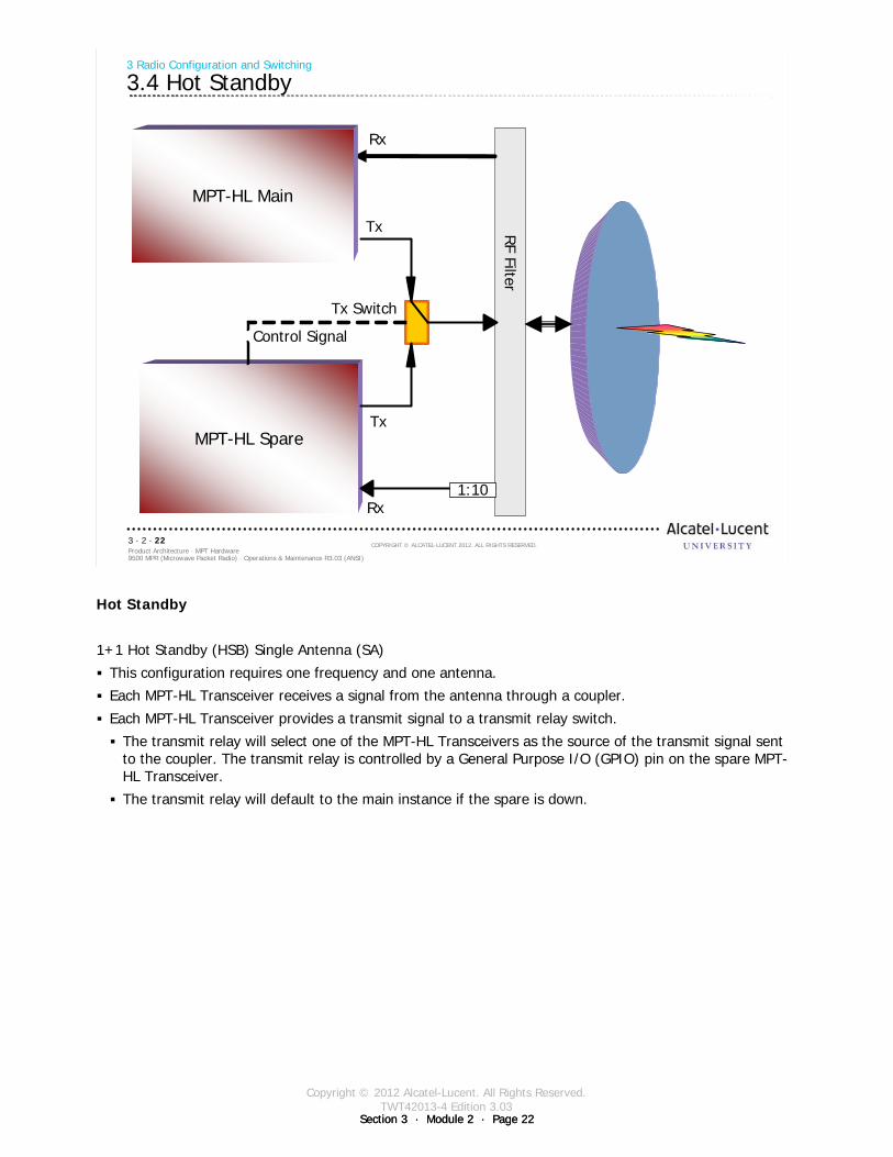
Copyright © 2012 Alcatel-Lucent. All Rights Reserved.TWT42013-4 Edition 3.03
Section 3 · Module 2 · Page 22Section 3 · Module 2 · Page 22
9500 MPR (Microwave Packet Radio) · Operations & Maintenance R3.03 (ANSI)Product Architecture · MPT Hardware3 · 2 · 22
COPYRIGHT © ALCATEL-LUCENT 2012. ALL RIGHTS RESERVED.
3 Radio Configuration and Switching
3.4 Hot Standby
MPT-HL Spare
MPT-HL Main
Control Signal
Tx Switch
RF Filter
Rx
Rx
Tx
Tx
1:10
Hot Standby
1+1 Hot Standby (HSB) Single Antenna (SA)
This configuration requires one frequency and one antenna.
Each MPT-HL Transceiver receives a signal from the antenna through a coupler.
Each MPT-HL Transceiver provides a transmit signal to a transmit relay switch.
The transmit relay will select one of the MPT-HL Transceivers as the source of the transmit signal sent to the coupler. The transmit relay is controlled by a General Purpose I/O (GPIO) pin on the spare MPT-HL Transceiver.
The transmit relay will default to the main instance if the spare is down.
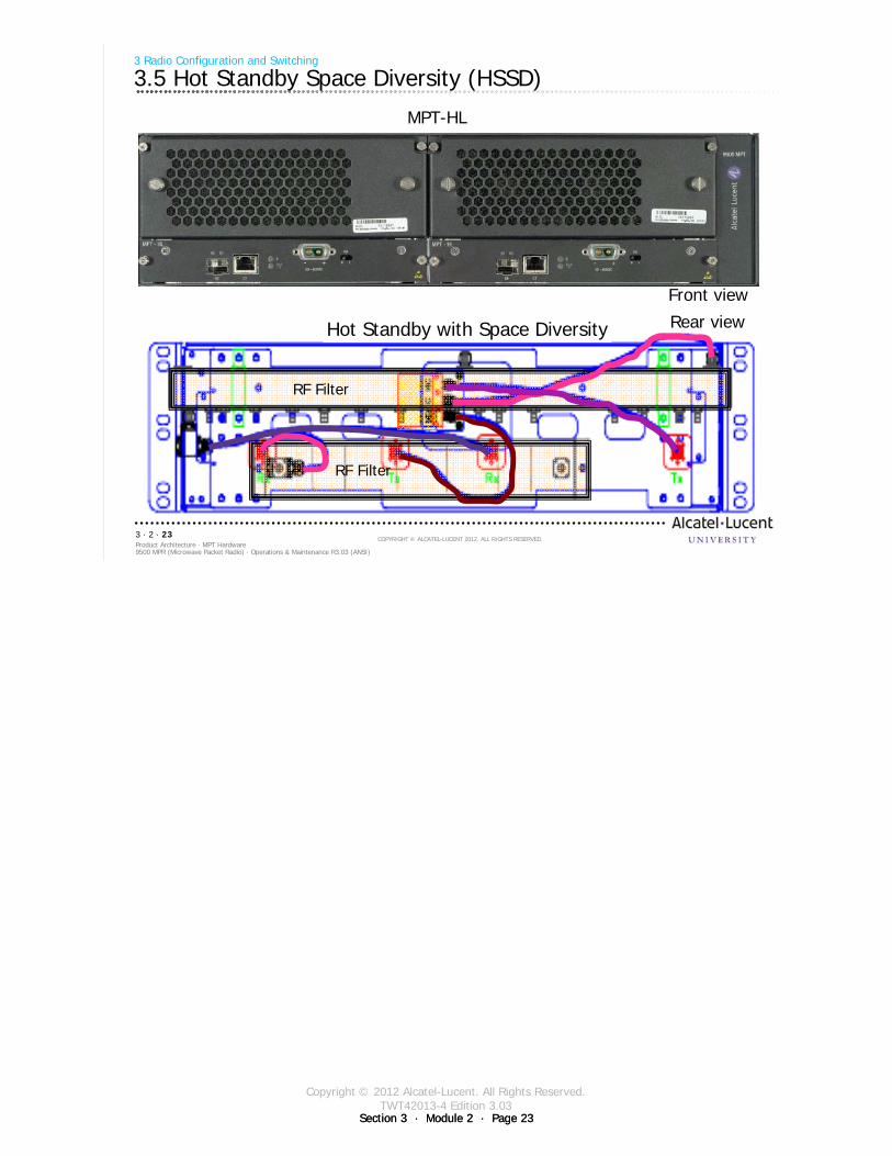
Copyright © 2012 Alcatel-Lucent. All Rights Reserved.TWT42013-4 Edition 3.03
Section 3 · Module 2 · Page 23Section 3 · Module 2 · Page 23
9500 MPR (Microwave Packet Radio) · Operations & Maintenance R3.03 (ANSI)Product Architecture · MPT Hardware3 · 2 · 23
COPYRIGHT © ALCATEL-LUCENT 2012. ALL RIGHTS RESERVED.
3 Radio Configuration and Switching
3.5 Hot Standby Space Diversity (HSSD)
Front view
Rear view
RF Filter
Hot Standby with Space Diversity
RF Filter
MPT-HL
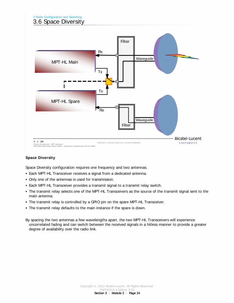
Copyright © 2012 Alcatel-Lucent. All Rights Reserved.TWT42013-4 Edition 3.03
Section 3 · Module 2 · Page 24Section 3 · Module 2 · Page 24
9500 MPR (Microwave Packet Radio) · Operations & Maintenance R3.03 (ANSI)Product Architecture · MPT Hardware3 · 2 · 24
COPYRIGHT © ALCATEL-LUCENT 2012. ALL RIGHTS RESERVED.
3 Radio Configuration and Switching
3.6 Space Diversity
MPT-HL Main
MPT-HL Spare
Rx
Rx
Tx
Tx
Waveguide
WaveguideFilter
Filter
Space Diversity
Space Diversity configuration requires one frequency and two antennas.
Each MPT-HL Transceiver receives a signal from a dedicated antenna.
Only one of the antennas is used for transmission.
Each MPT-HL Transceiver provides a transmit signal to a transmit relay switch.
The transmit relay selects one of the MPT-HL Transceivers as the source of the transmit signal sent to themain antenna.
The transmit relay is controlled by a GPIO pin on the spare MPT-HL Transceiver.
The transmit relay defaults to the main instance if the spare is down.
By spacing the two antennas a few wavelengths apart, the two MPT-HL Transceivers will experience uncorrelated fading and can switch between the received signals in a hitless manner to provide a greater degree of availability over the radio link.
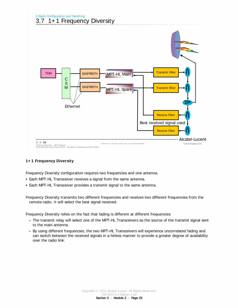
Copyright © 2012 Alcatel-Lucent. All Rights Reserved.TWT42013-4 Edition 3.03
Section 3 · Module 2 · Page 25Section 3 · Module 2 · Page 25
1+1 Frequency Diversity
Frequency Diversity configuration requires two frequencies and one antenna.
Each MPT-HL Transceiver receives a signal from the same antenna.
Each MPT-HL Transceiver provides a transmit signal to the same antenna.
Frequency Diversity transmits two different frequencies and receives two different frequencies from the remote-radio. It will select the best signal received.
Frequency Diversity relies on the fact that fading is different at different frequencies:
The transmit relay will select one of the MPT-HL Transceivers as the source of the transmit signal sent to the main antenna.
By using different frequencies, the two MPT-HL Transceivers will experience uncorrelated fading and can switch between the received signals in a hitless manner to provide a greater degree of availability over the radio link.
9500 MPR (Microwave Packet Radio) · Operations & Maintenance R3.03 (ANSI)Product Architecture · MPT Hardware3 · 2 · 25
COPYRIGHT © ALCATEL-LUCENT 2012. ALL RIGHTS RESERVED.
3 Radio Configuration and Switching
3.7 1+1 Frequency Diversity
Transmit Filter
Transmit Filter
Receive Filter
Receive Filter
EAS/P8ETH
EAS/P8ETH
CSM
TDM
Ethernet
Best received signal used
MPT-HL Main
MPT-HL Spare

Copyright © 2012 Alcatel-Lucent. All Rights Reserved.TWT42013-4 Edition 3.03
Section 3 · Module 2 · Page 26Section 3 · Module 2 · Page 26
9500 MPR (Microwave Packet Radio) · Operations & Maintenance R3.03 (ANSI)Product Architecture · MPT Hardware3 · 2 · 26
COPYRIGHT © ALCATEL-LUCENT 2012. ALL RIGHTS RESERVED.
Blank page
Switch to notes view!
This page intentionally left blank

Copyright © 2012 Alcatel-Lucent. All Rights Reserved.TWT42013-4 Edition 3.03
Section 3 · Module 2 · Page 27Section 3 · Module 2 · Page 27
9500 MPR (Microwave Packet Radio) · Operations & Maintenance R3.03 (ANSI)Product Architecture · MPT Hardware3 · 2 · 27
COPYRIGHT © ALCATEL-LUCENT 2012. ALL RIGHTS RESERVED.
4 All Indoor Mount Configurations
Refer to 9500 MPR Product Information, 3EM23952AHAA, 9500 MPR General System Description
for more details
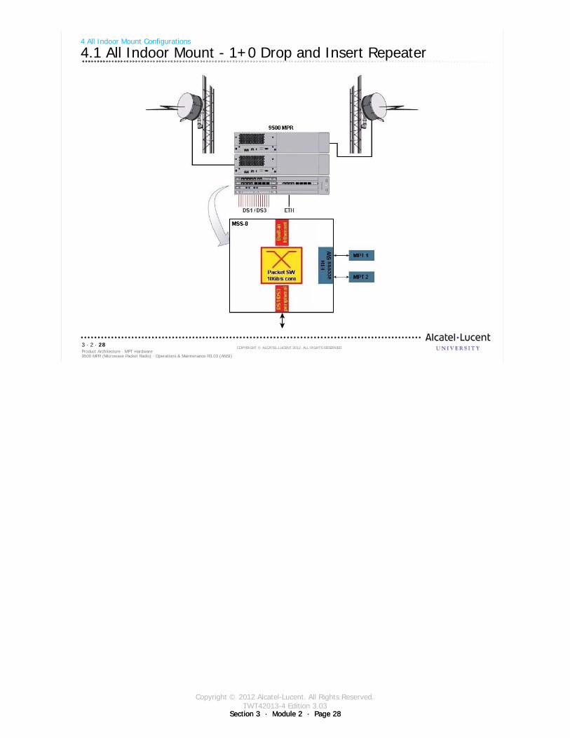
Copyright © 2012 Alcatel-Lucent. All Rights Reserved.TWT42013-4 Edition 3.03
Section 3 · Module 2 · Page 28Section 3 · Module 2 · Page 28
9500 MPR (Microwave Packet Radio) · Operations & Maintenance R3.03 (ANSI)Product Architecture · MPT Hardware3 · 2 · 28
COPYRIGHT © ALCATEL-LUCENT 2012. ALL RIGHTS RESERVED.
4 All Indoor Mount Configurations
4.1 All Indoor Mount - 1+0 Drop and Insert Repeater
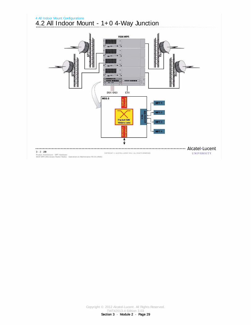
Copyright © 2012 Alcatel-Lucent. All Rights Reserved.TWT42013-4 Edition 3.03
Section 3 · Module 2 · Page 29Section 3 · Module 2 · Page 29
9500 MPR (Microwave Packet Radio) · Operations & Maintenance R3.03 (ANSI)Product Architecture · MPT Hardware3 · 2 · 29
COPYRIGHT © ALCATEL-LUCENT 2012. ALL RIGHTS RESERVED.
4 All Indoor Mount Configurations
4.2 All Indoor Mount - 1+0 4-Way Junction
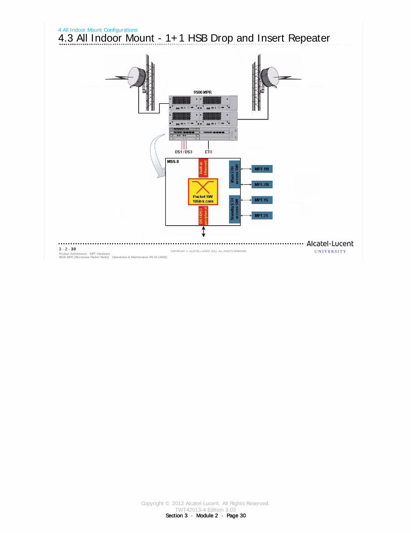
Copyright © 2012 Alcatel-Lucent. All Rights Reserved.TWT42013-4 Edition 3.03
Section 3 · Module 2 · Page 30Section 3 · Module 2 · Page 30
9500 MPR (Microwave Packet Radio) · Operations & Maintenance R3.03 (ANSI)Product Architecture · MPT Hardware3 · 2 · 30
COPYRIGHT © ALCATEL-LUCENT 2012. ALL RIGHTS RESERVED.
4 All Indoor Mount Configurations
4.3 All Indoor Mount - 1+1 HSB Drop and Insert Repeater
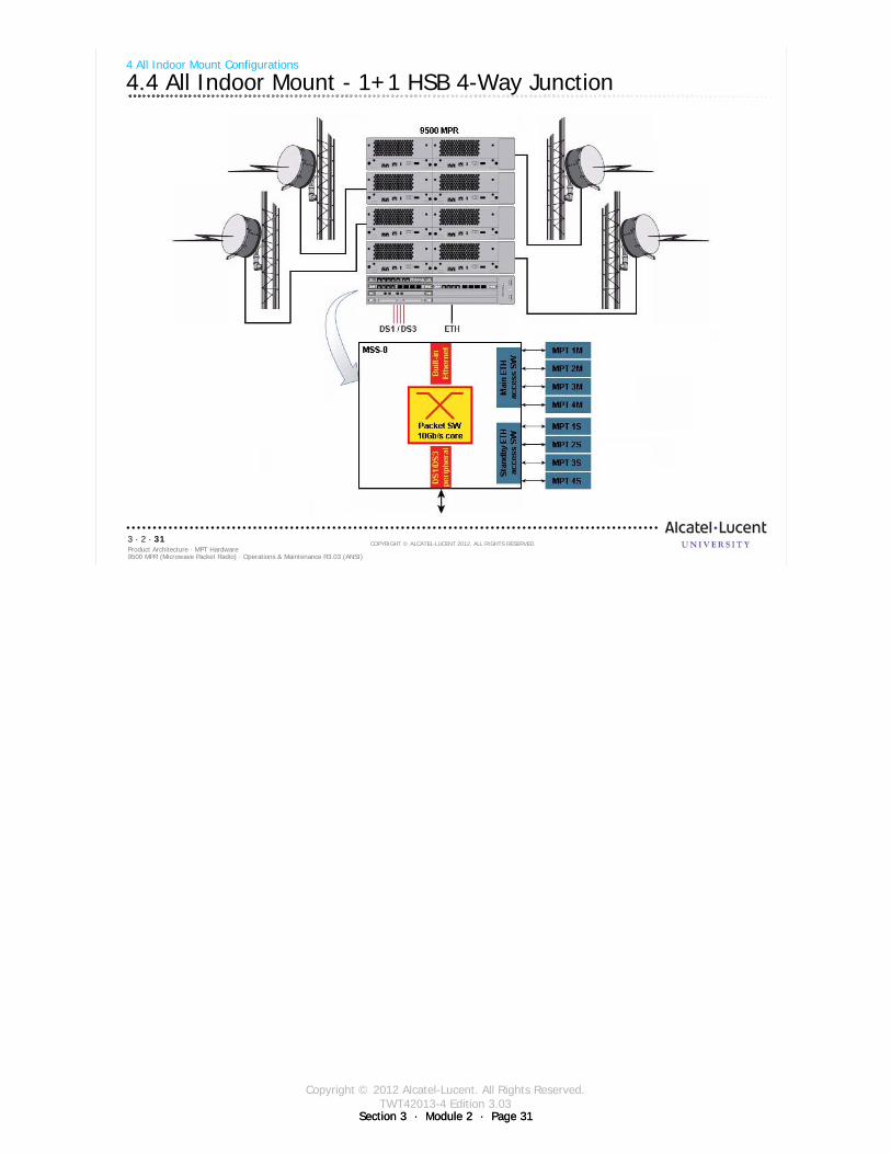
Copyright © 2012 Alcatel-Lucent. All Rights Reserved.TWT42013-4 Edition 3.03
Section 3 · Module 2 · Page 31Section 3 · Module 2 · Page 31
9500 MPR (Microwave Packet Radio) · Operations & Maintenance R3.03 (ANSI)Product Architecture · MPT Hardware3 · 2 · 31
COPYRIGHT © ALCATEL-LUCENT 2012. ALL RIGHTS RESERVED.
4 All Indoor Mount Configurations
4.4 All Indoor Mount - 1+1 HSB 4-Way Junction

Copyright © 2012 Alcatel-Lucent. All Rights Reserved.TWT42013-4 Edition 3.03
Section 3 · Module 2 · Page 32Section 3 · Module 2 · Page 32
9500 MPR (Microwave Packet Radio) · Operations & Maintenance R3.03 (ANSI)Product Architecture · MPT Hardware3 · 2 · 32
COPYRIGHT © ALCATEL-LUCENT 2012. ALL RIGHTS RESERVED.
Blank page
Switch to notes view!
This page intentionally left blank

Copyright © 2012 Alcatel-Lucent. All Rights Reserved.TWT42013-4 Edition 3.03
Section 3 · Module 2 · Page 33Section 3 · Module 2 · Page 33
9500 MPR (Microwave Packet Radio) · Operations & Maintenance R3.03 (ANSI)Product Architecture · MPT Hardware3 · 2 · 33
COPYRIGHT © ALCATEL-LUCENT 2012. ALL RIGHTS RESERVED.
5 Characteristics

Copyright © 2012 Alcatel-Lucent. All Rights Reserved.TWT42013-4 Edition 3.03
Section 3 · Module 2 · Page 34Section 3 · Module 2 · Page 34
9500 MPR (Microwave Packet Radio) · Operations & Maintenance R3.03 (ANSI)Product Architecture · MPT Hardware3 · 2 · 34
COPYRIGHT © ALCATEL-LUCENT 2012. ALL RIGHTS RESERVED.
5 Characteristics
5.1 TDM Circuit Service Profile example
Note: For additional modulation options, refer to the documentation
Frequency BW
Channel BW
MHz
Modulation
QAM
Maximum Radio Link
or Eth Capacity
Mb/s
Equivalent CapacityTDM2ETH
Ethernet Link
DS1
Equivalent Capacity
TDM2TDM
Radio Link
DS1
5.8 10 32 37.32 18 22
5.8, 6L, 6U, 11 5 128 25.8
5.8, 6L, 6U, 11 10 128 52.64 25 31
5.8 30 32 114.22 55 67
5.8, 6L, 6U, 11 30 128 160.17 78 95
5.8, 6L, 6U, 11 30 128 183.30 89 108
The table summaries the relations among Radio capacity, channeling scheme, and modulation (Static Modulation).
The relationship of these parameters will be covered again when we discuss the channel bandwidth, modulation and capacity settings using the GUI.
Copyright © 2012 Alcatel-Lucent. All Rights Reserved.TWT42013-4 Edition 3.03
Section 3 · Module 2 · Page 35Section 3 · Module 2 · Page 35
9500 MPR (Microwave Packet Radio) · Operations & Maintenance R3.03 (ANSI)Product Architecture · MPT Hardware3 · 2 · 35
COPYRIGHT © ALCATEL-LUCENT 2012. ALL RIGHTS RESERVED.
Module summary
Functionality of the MPT-HLRadio TransceiverMPT-HL to RFMPT-HL from MSS-8
Radio Configuration and Switching1+0 unprotected1+1 Hot Standby (HSB)Hot Standby Space Diversity (HSSD)Frequency Diversity
MPT-HL Characteristics

Copyright © 2012 Alcatel-Lucent. All Rights Reserved.TWT42013-4 Edition 3.03
Section 3 · Module 2 · Page 36Section 3 · Module 2 · Page 36
9500 MPR (Microwave Packet Radio) · Operations & Maintenance R3.03 (ANSI)Product Architecture · MPT Hardware3 · 2 · 36
COPYRIGHT © ALCATEL-LUCENT 2012. ALL RIGHTS RESERVED.
Blank page
Switch to notes view!
This page intentionally left blank

Copyright © 2012 Alcatel-Lucent. All Rights Reserved.TWT42013-4 Edition 3.03
Section 3 · Module 2 · Page 37Section 3 · Module 2 · Page 37
9500 MPR (Microwave Packet Radio) · Operations & Maintenance R3.03 (ANSI)Product Architecture · MPT Hardware3 · 2 · 37
COPYRIGHT © ALCATEL-LUCENT 2012. ALL RIGHTS RESERVED.
Exercise
Time allowed:
Lab Exercise 19500 MPR Hardware Orientation

Copyright © 2012 Alcatel-Lucent. All Rights Reserved.TWT42013-4 Edition 3.03
Section 3 · Module 2 · Page 38Section 3 · Module 2 · Page 38
9500 MPR (Microwave Packet Radio) · Operations & Maintenance R3.03 (ANSI)Product Architecture · MPT Hardware3 · 2 · 38
COPYRIGHT © ALCATEL-LUCENT 2012. ALL RIGHTS RESERVED.
End of moduleMPT Hardware

Copyright © 2012 Alcatel-Lucent. All Rights Reserved. TWT42013-5 Edition 3.03
Section 3 · Module 3 · Page 1
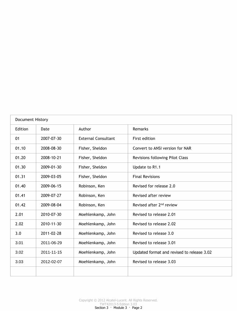
Copyright © 2012 Alcatel-Lucent. All Rights Reserved. TWT42013-5 Edition 3.03
Section 3 · Module 3 · Page 2
This page is left blank intentionally
Document History
Edition Date Author Remarks
01 2007-07-30 External Consultant First edition
01.10 2008-08-30 Fisher, Sheldon Convert to ANSI version for NAR
01.20 2008-10-21 Fisher, Sheldon Revisions following Pilot Class
01.30 2009-01-30 Fisher, Sheldon Update to R1.1
01.31 2009-03-05 Fisher, Sheldon Final Revisions
01.40 2009-06-15 Robinson, Ken Revised for release 2.0
01.41 2009-07-27 Robinson, Ken Revised after review
01.42 2009-08-04 Robinson, Ken Revised after 2nd review
2.01 2010-07-30 Moehlenkamp, John Revised to release 2.01
2.02 2010-11-30 Moehlenkamp, John Revised to release 2.02
3.0 2011-02-28 Moehlenkamp, John Revised to release 3.0
3.01 2011-06-29 Moehlenkamp, John Revised to release 3.01
3.02 2011-11-15 Moehlenkamp, John Updated format and revised to release 3.02
3.03 2012-02-07 Moehlenkamp, John Revised to release 3.03
Copyright © 2012 Alcatel-Lucent. All Rights Reserved. TWT42013-5 Edition 3.03
Section 3 · Module 3 · Page 3

Copyright © 2012 Alcatel-Lucent. All Rights Reserved. TWT42013-5 Edition 3.03
Section 3 · Module 3 · Page 4
This page is left blank intentionally
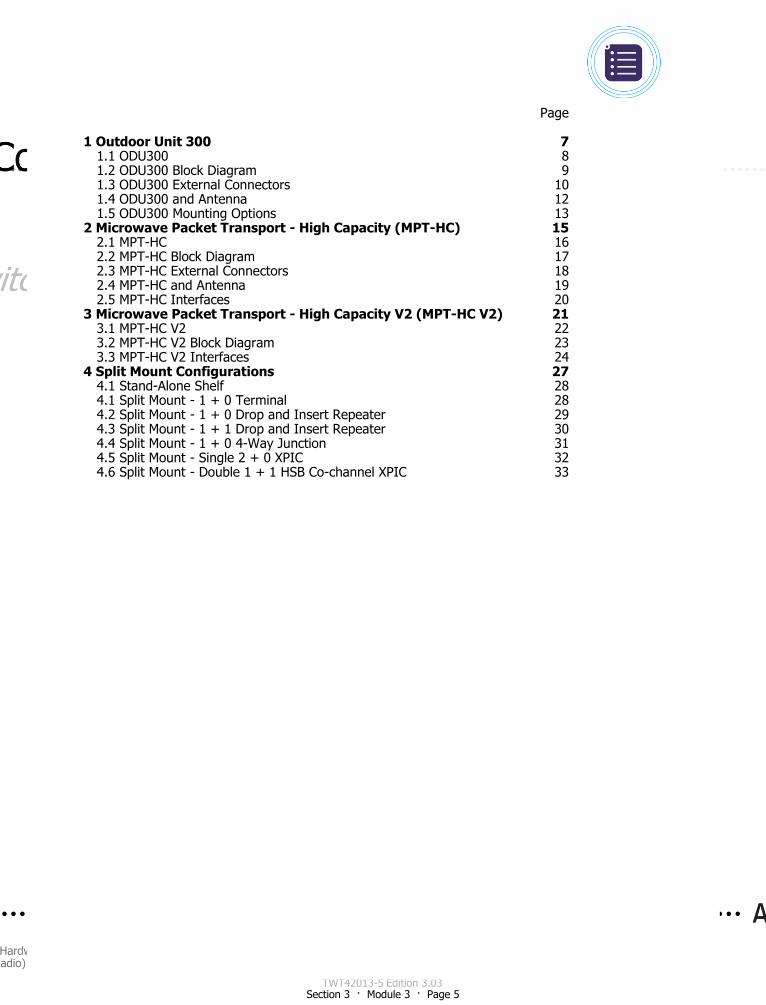
Copyright © 2012 Alcatel-Lucent. All Rights Reserved. TWT42013-5 Edition 3.03
Section 3 · Module 3 · Page 5
Page
1 Outdoor Unit 300 7 1.1 ODU300 8 1.2 ODU300 Block Diagram 9 1.3 ODU300 External Connectors 10 1.4 ODU300 and Antenna 12 1.5 ODU300 Mounting Options 13
2 Microwave Packet Transport - High Capacity (MPT-HC) 15 2.1 MPT-HC 16 2.2 MPT-HC Block Diagram 17 2.3 MPT-HC External Connectors 18 2.4 MPT-HC and Antenna 19 2.5 MPT-HC Interfaces 20
3 Microwave Packet Transport - High Capacity V2 (MPT-HC V2) 21 3.1 MPT-HC V2 22 3.2 MPT-HC V2 Block Diagram 23 3.3 MPT-HC V2 Interfaces 24
4 Split Mount Configurations 27 4.1 Stand-Alone Shelf 28 4.1 Split Mount - 1 + 0 Terminal 28 4.2 Split Mount - 1 + 0 Drop and Insert Repeater 29 4.3 Split Mount - 1 + 1 Drop and Insert Repeater 30 4.4 Split Mount - 1 + 0 4-Way Junction 31 4.5 Split Mount - Single 2 + 0 XPIC 32 4.6 Split Mount - Double 1 + 1 HSB Co-channel XPIC 33

Copyright © 2012 Alcatel-Lucent. All Rights Reserved. TWT42013-5 Edition 3.03
Section 3 · Module 3 · Page 6
This page is left blank intentionally
Copyright © 2012 Alcatel-Lucent. All Rights Reserved. TWT42013-5 Edition 3.03
Section 3 · Module 3 · Page 7
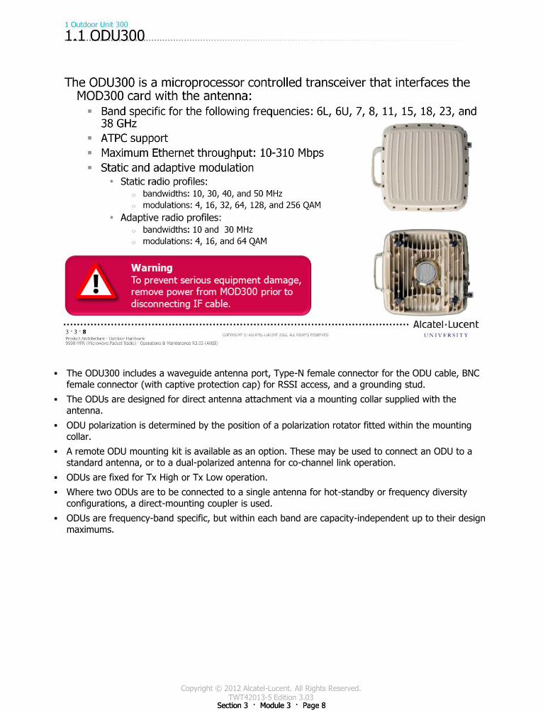
Copyright © 2012 Alcatel-Lucent. All Rights Reserved. TWT42013-5 Edition 3.03
Section 3 · Module 3 · Page 8 Section 3 · Module 3 · Page 8
The ODU300 includes a waveguide antenna port, Type-N female connector for the ODU cable, BNC female connector (with captive protection cap) for RSSI access, and a grounding stud.
The ODUs are designed for direct antenna attachment via a mounting collar supplied with the antenna.
ODU polarization is determined by the position of a polarization rotator fitted within the mounting collar.
A remote ODU mounting kit is available as an option. These may be used to connect an ODU to a standard antenna, or to a dual-polarized antenna for co-channel link operation.
ODUs are fixed for Tx High or Tx Low operation.
Where two ODUs are to be connected to a single antenna for hot-standby or frequency diversity configurations, a direct-mounting coupler is used.
ODUs are frequency-band specific, but within each band are capacity-independent up to their design maximums.
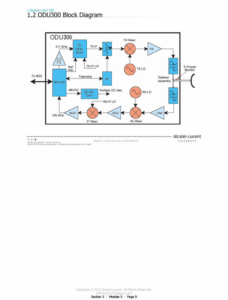
Copyright © 2012 Alcatel-Lucent. All Rights Reserved. TWT42013-5 Edition 3.03
Section 3 · Module 3 · Page 9 Section 3 · Module 3 · Page 9

Copyright © 2012 Alcatel-Lucent. All Rights Reserved. TWT42013-5 Edition 3.03
Section 3 · Module 3 · Page 10 Section 3 · Module 3 · Page 10
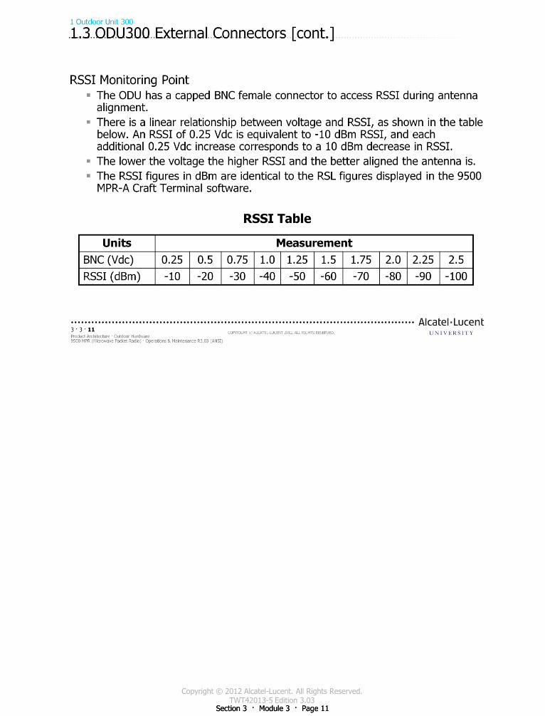
Copyright © 2012 Alcatel-Lucent. All Rights Reserved. TWT42013-5 Edition 3.03
Section 3 · Module 3 · Page 11 Section 3 · Module 3 · Page 11
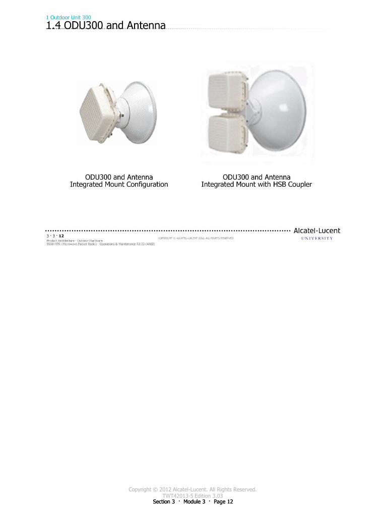
Copyright © 2012 Alcatel-Lucent. All Rights Reserved. TWT42013-5 Edition 3.03
Section 3 · Module 3 · Page 12 Section 3 · Module 3 · Page 12
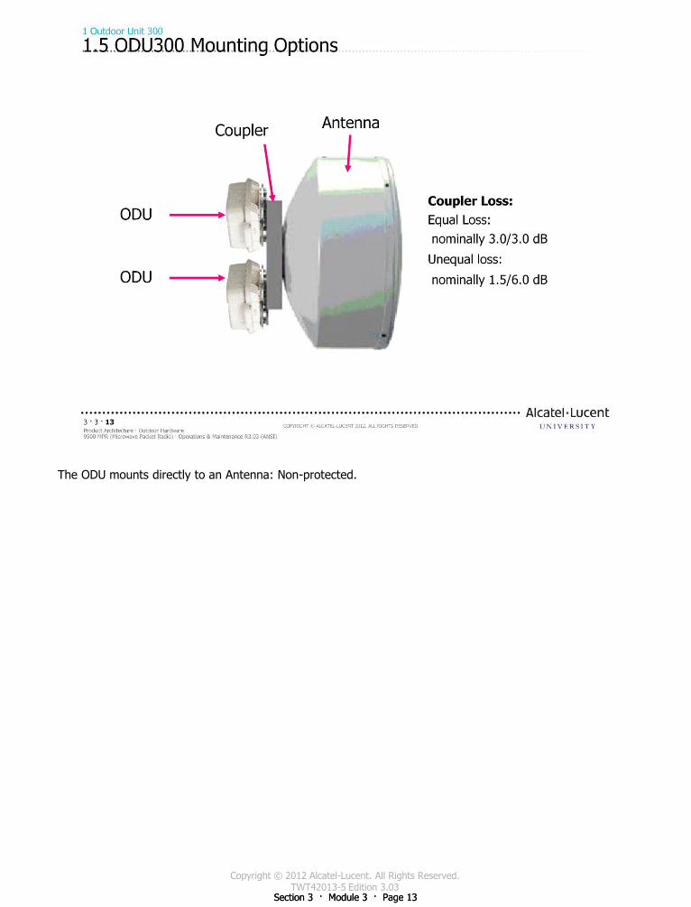
Copyright © 2012 Alcatel-Lucent. All Rights Reserved. TWT42013-5 Edition 3.03
Section 3 · Module 3 · Page 13 Section 3 · Module 3 · Page 13
The ODU mounts directly to an Antenna: Non-protected.

Copyright © 2012 Alcatel-Lucent. All Rights Reserved. TWT42013-5 Edition 3.03
Section 3 · Module 3 · Page 14 Section 3 · Module 3 · Page 14
This page intentionally left blank
Copyright © 2012 Alcatel-Lucent. All Rights Reserved. TWT42013-5 Edition 3.03
Section 3 · Module 3 · Page 15
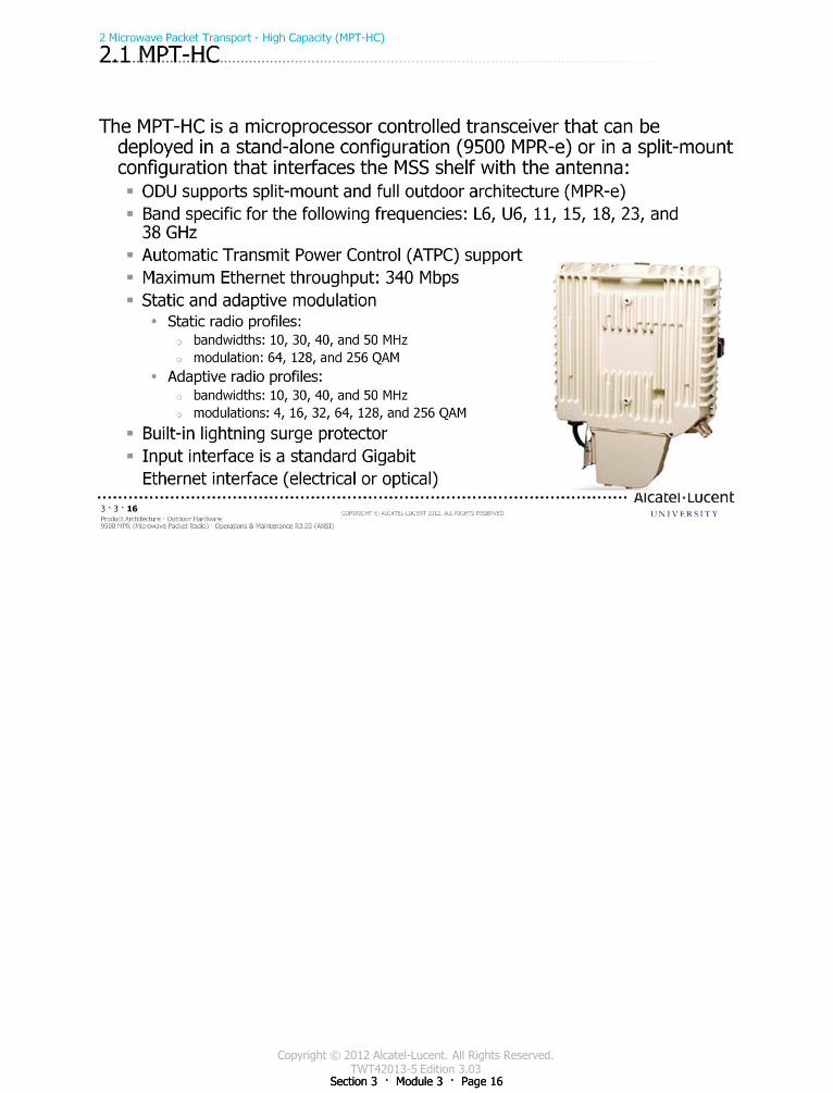
Copyright © 2012 Alcatel-Lucent. All Rights Reserved. TWT42013-5 Edition 3.03
Section 3 · Module 3 · Page 16 Section 3 · Module 3 · Page 16
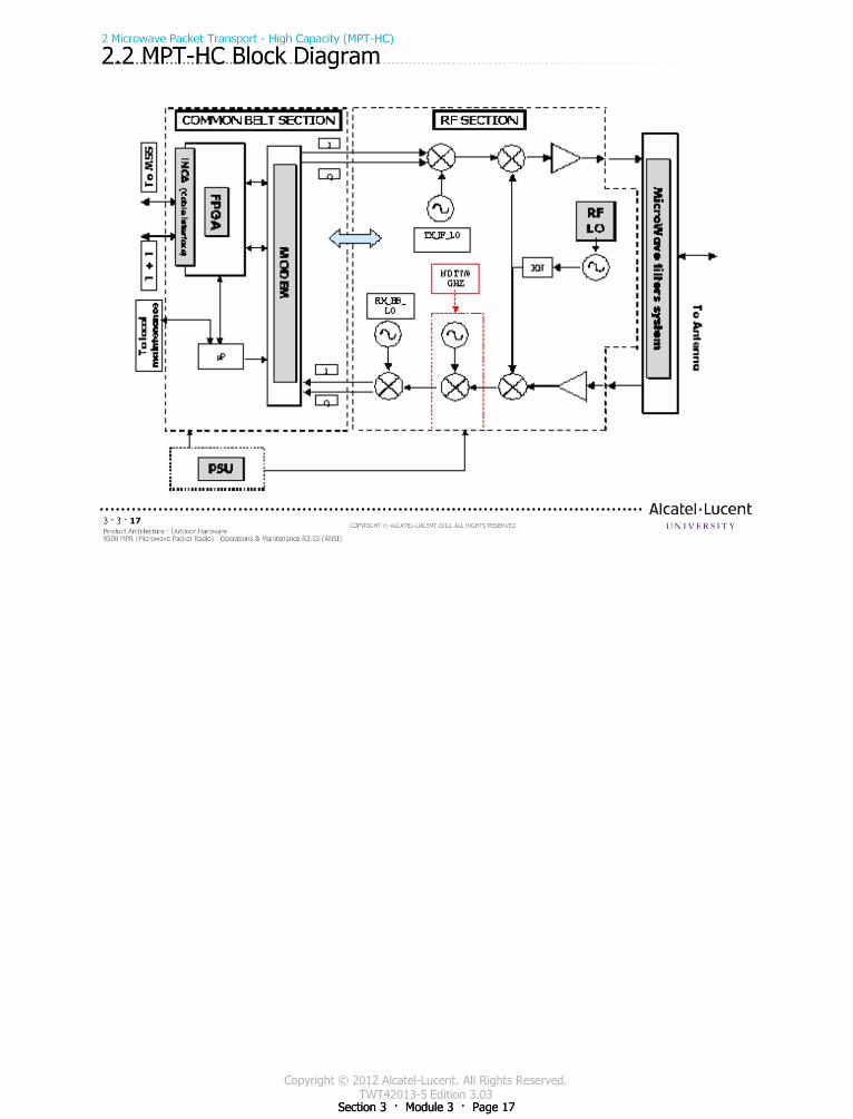
Copyright © 2012 Alcatel-Lucent. All Rights Reserved. TWT42013-5 Edition 3.03
Section 3 · Module 3 · Page 17 Section 3 · Module 3 · Page 17
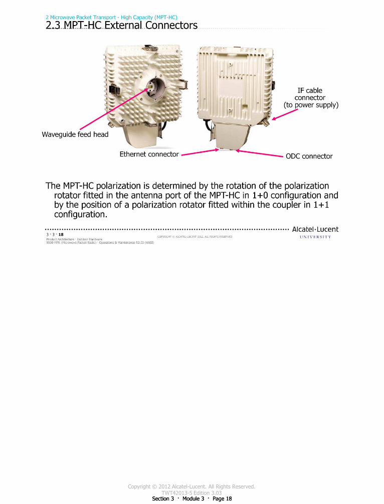
Copyright © 2012 Alcatel-Lucent. All Rights Reserved. TWT42013-5 Edition 3.03
Section 3 · Module 3 · Page 18 Section 3 · Module 3 · Page 18
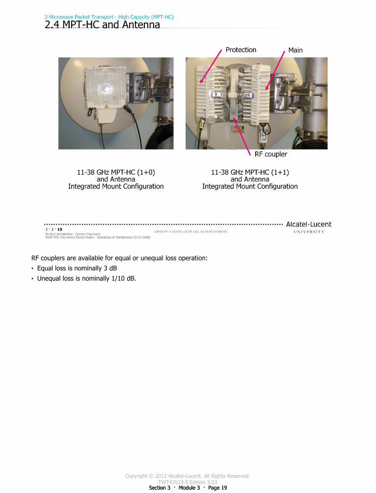
Copyright © 2012 Alcatel-Lucent. All Rights Reserved. TWT42013-5 Edition 3.03
Section 3 · Module 3 · Page 19 Section 3 · Module 3 · Page 19
RF couplers are available for equal or unequal loss operation:
• Equal loss is nominally 3 dB
• Unequal loss is nominally 1/10 dB.
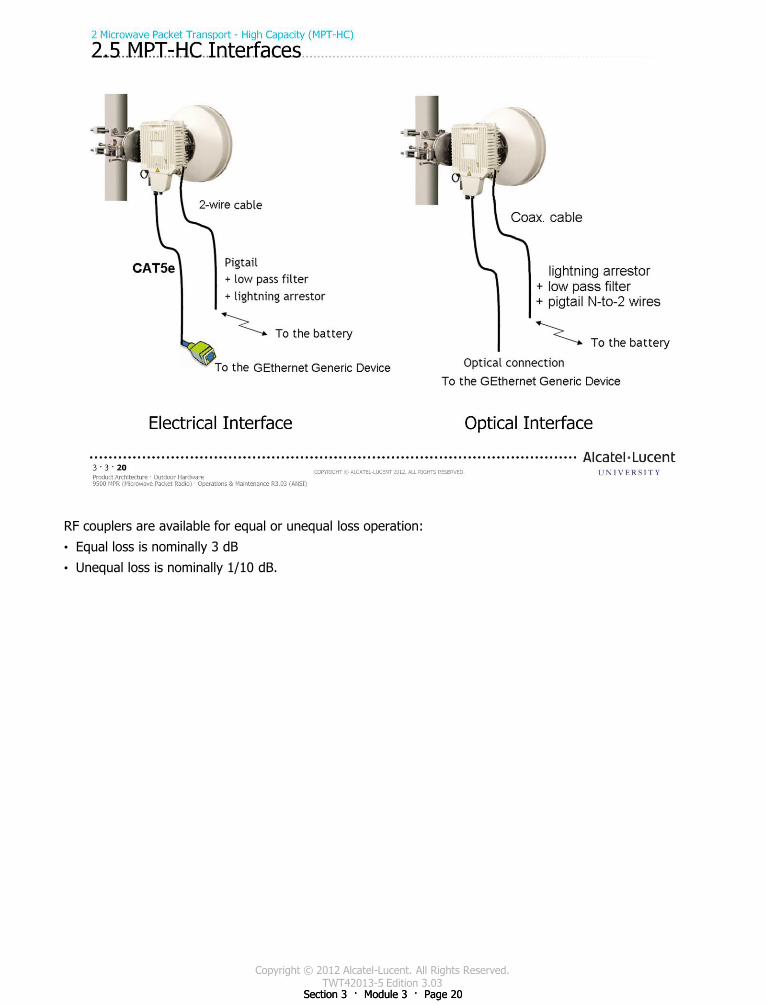
Copyright © 2012 Alcatel-Lucent. All Rights Reserved. TWT42013-5 Edition 3.03
Section 3 · Module 3 · Page 20 Section 3 · Module 3 · Page 20
RF couplers are available for equal or unequal loss operation:
• Equal loss is nominally 3 dB
• Unequal loss is nominally 1/10 dB.
Copyright © 2012 Alcatel-Lucent. All Rights Reserved. TWT42013-5 Edition 3.03
Section 3 · Module 3 · Page 21
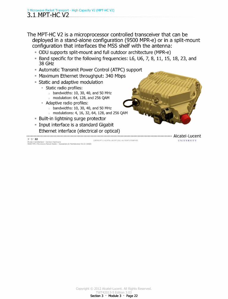
Copyright © 2012 Alcatel-Lucent. All Rights Reserved. TWT42013-5 Edition 3.03
Section 3 · Module 3 · Page 22 Section 3 · Module 3 · Page 22
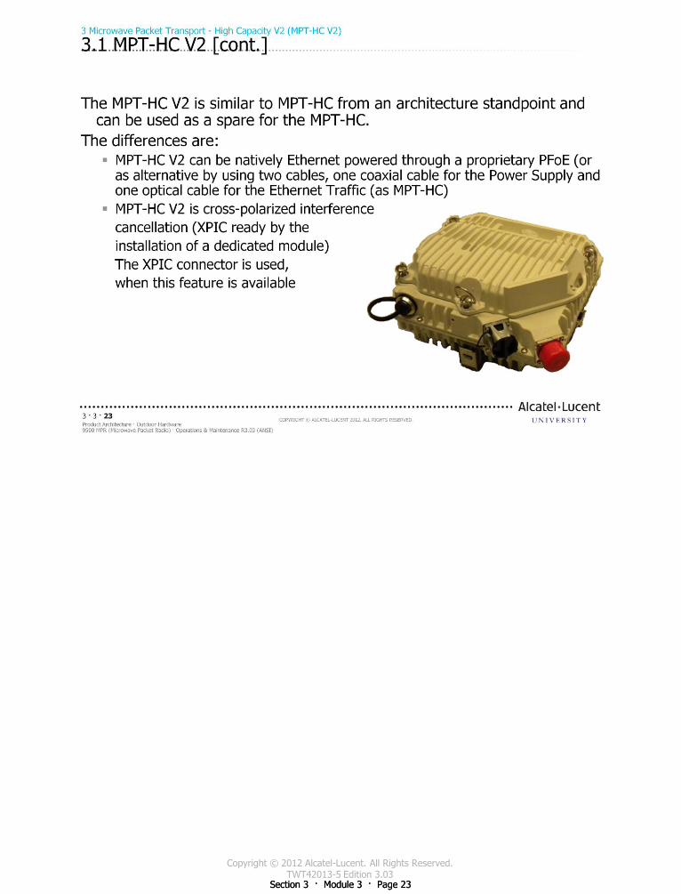
Copyright © 2012 Alcatel-Lucent. All Rights Reserved. TWT42013-5 Edition 3.03
Section 3 · Module 3 · Page 23 Section 3 · Module 3 · Page 23
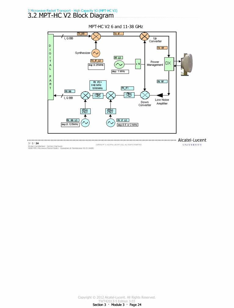
Copyright © 2012 Alcatel-Lucent. All Rights Reserved. TWT42013-5 Edition 3.03
Section 3 · Module 3 · Page 24 Section 3 · Module 3 · Page 24
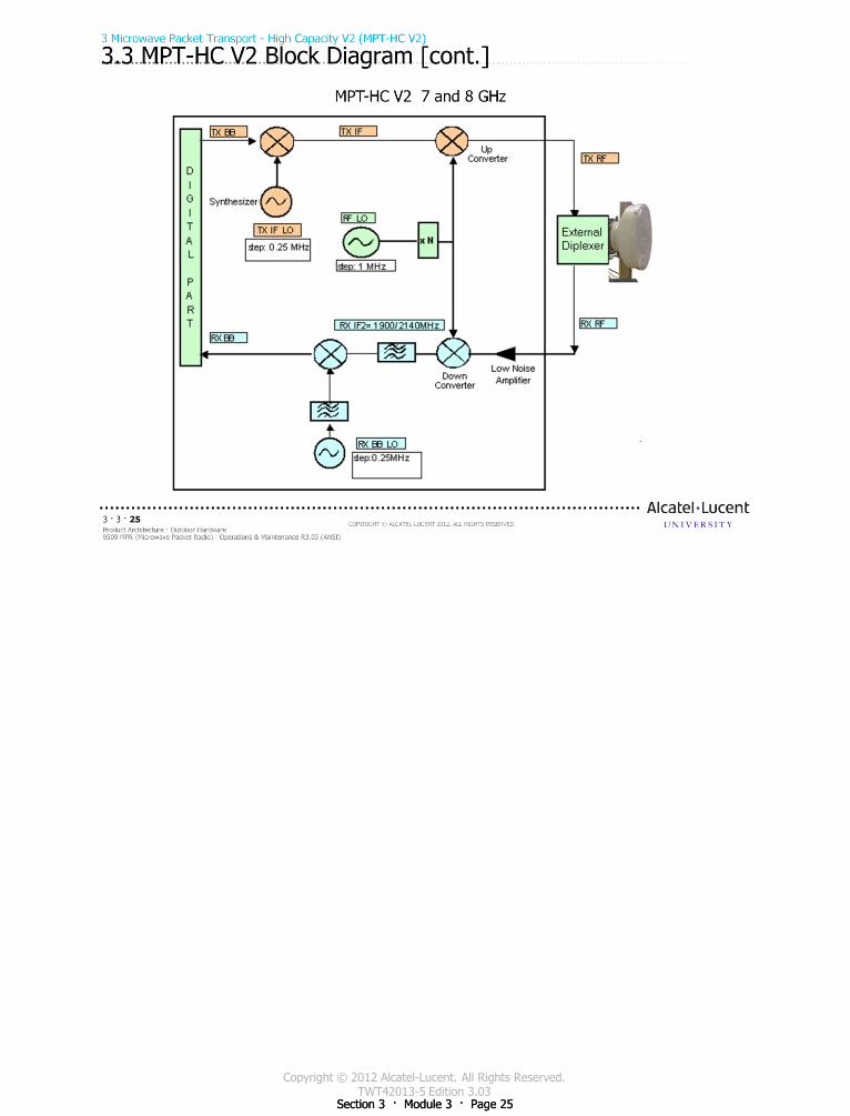
Copyright © 2012 Alcatel-Lucent. All Rights Reserved. TWT42013-5 Edition 3.03
Section 3 · Module 3 · Page 25 Section 3 · Module 3 · Page 25
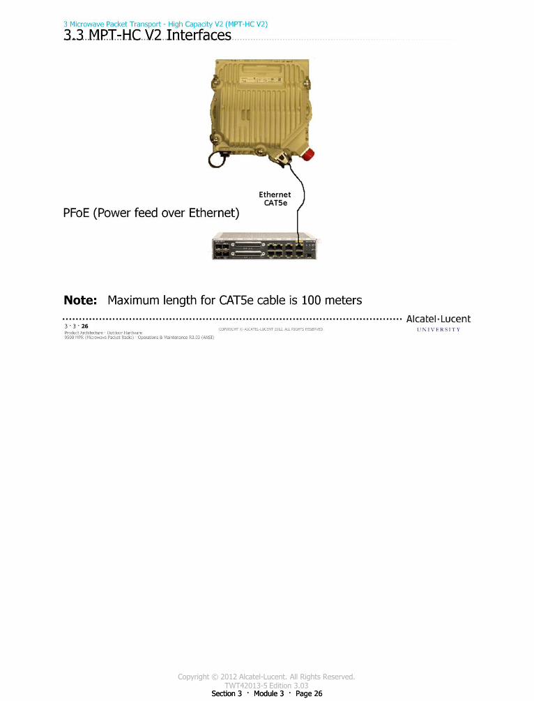
Copyright © 2012 Alcatel-Lucent. All Rights Reserved. TWT42013-5 Edition 3.03
Section 3 · Module 3 · Page 26 Section 3 · Module 3 · Page 26
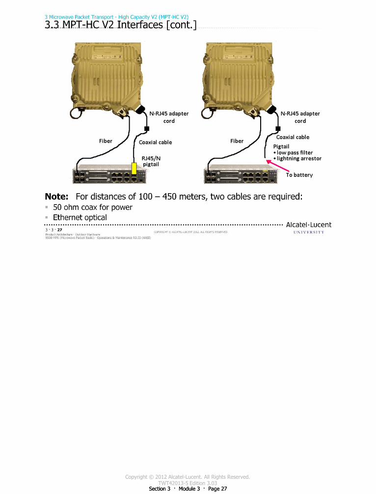
Copyright © 2012 Alcatel-Lucent. All Rights Reserved. TWT42013-5 Edition 3.03
Section 3 · Module 3 · Page 27 Section 3 · Module 3 · Page 27
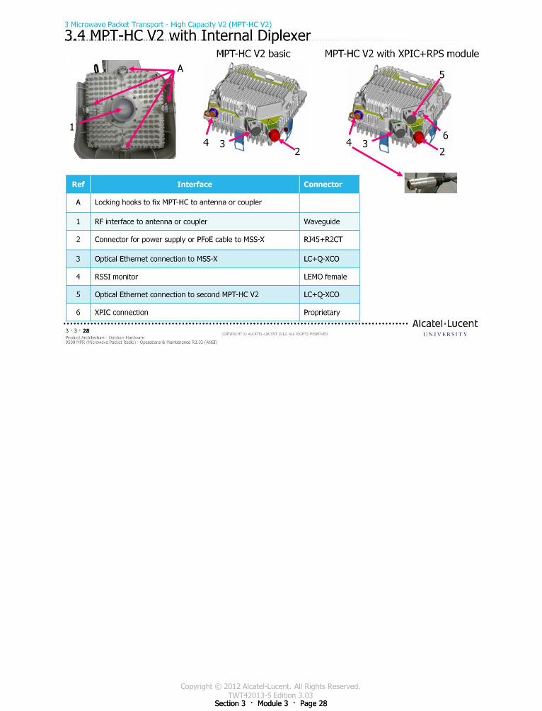
Copyright © 2012 Alcatel-Lucent. All Rights Reserved. TWT42013-5 Edition 3.03
Section 3 · Module 3 · Page 28 Section 3 · Module 3 · Page 28
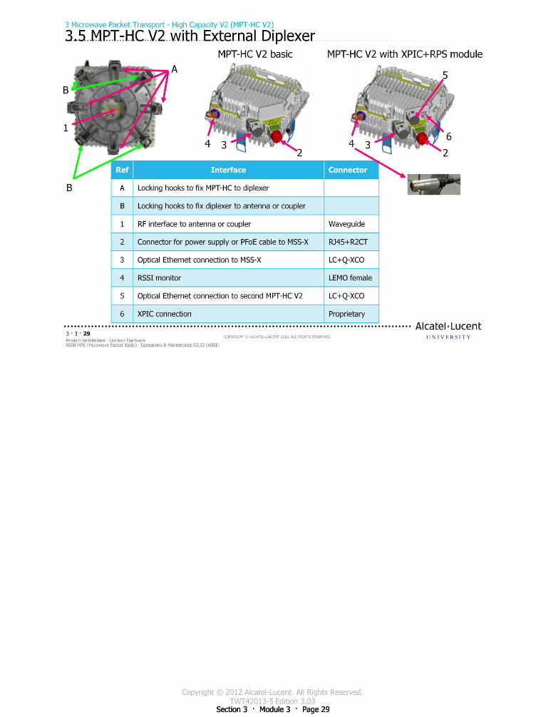
Copyright © 2012 Alcatel-Lucent. All Rights Reserved. TWT42013-5 Edition 3.03
Section 3 · Module 3 · Page 29 Section 3 · Module 3 · Page 29
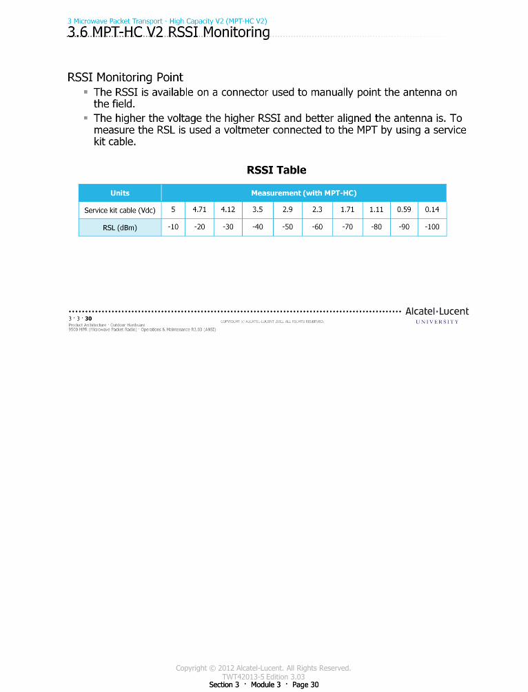
Copyright © 2012 Alcatel-Lucent. All Rights Reserved. TWT42013-5 Edition 3.03
Section 3 · Module 3 · Page 30 Section 3 · Module 3 · Page 30
Copyright © 2012 Alcatel-Lucent. All Rights Reserved. TWT42013-5 Edition 3.03
Section 3 · Module 3 · Page 31
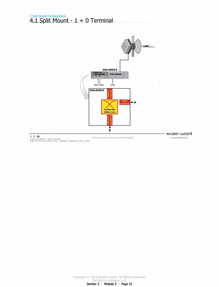
Copyright © 2012 Alcatel-Lucent. All Rights Reserved. TWT42013-5 Edition 3.03
Section 3 · Module 3 · Page 32 Section 3 · Module 3 · Page 32
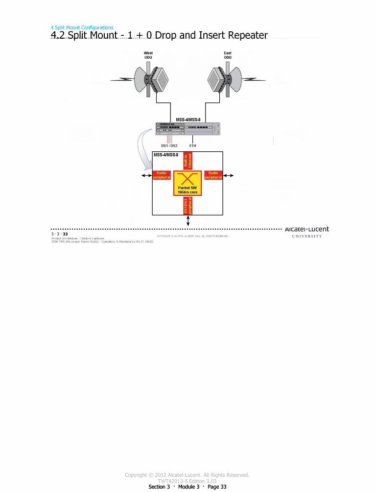
Copyright © 2012 Alcatel-Lucent. All Rights Reserved. TWT42013-5 Edition 3.03
Section 3 · Module 3 · Page 33 Section 3 · Module 3 · Page 33

Copyright © 2012 Alcatel-Lucent. All Rights Reserved. TWT42013-5 Edition 3.03
Section 3 · Module 3 · Page 34 Section 3 · Module 3 · Page 34
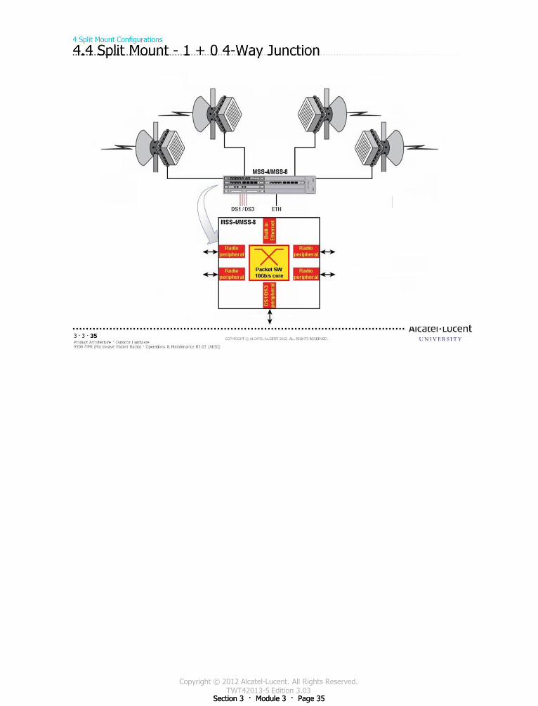
Copyright © 2012 Alcatel-Lucent. All Rights Reserved. TWT42013-5 Edition 3.03
Section 3 · Module 3 · Page 35 Section 3 · Module 3 · Page 35
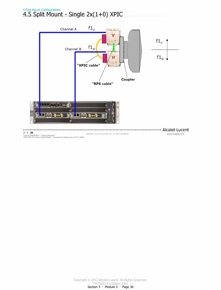
Copyright © 2012 Alcatel-Lucent. All Rights Reserved. TWT42013-5 Edition 3.03
Section 3 · Module 3 · Page 36
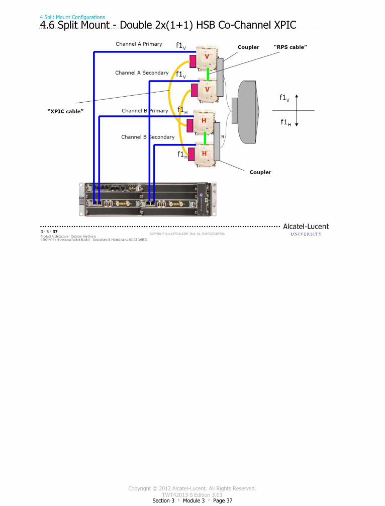
Copyright © 2012 Alcatel-Lucent. All Rights Reserved. TWT42013-5 Edition 3.03
Section 3 · Module 3 · Page 37
Copyright © 2012 Alcatel-Lucent. All Rights Reserved. TWT42013-5 Edition 3.03
Section 3 · Module 3 · Page 38 Section 3 · Module 3 · Page 38

Copyright © 2012 Alcatel-Lucent. All Rights Reserved. TWT42013-5 Edition 3.03
Section 3 · Module 3 · Page 39 Section 3 · Module 3 · Page 39
This page intentionally left blank

Copyright © 2012 Alcatel-Lucent. All Rights Reserved. TWT42013-5 Edition 3.03
Section 3 · Module 3 · Page 40 Section 3 · Module 3 · Page 40

Copyright © 2012 Alcatel-Lucent. All Rights Reserved.TWT42013-6 Edition 3.03
Section 4 · Module 1 · Page 1
Do not delete this graphic elements in here:
All Rights Reserved © Alcatel-Lucent @@YEAR
Module 1Operator GUI Interface
TWT42013-6 Edition 3.03
Section 4NE Operation
9500 MPR (Microwave Packet Radio)Operations & Maintenance R3.03 (ANSI)
TWT42013 Edition 1.1
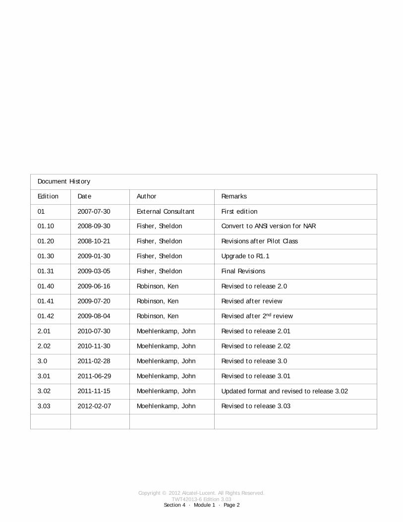
Copyright © 2012 Alcatel-Lucent. All Rights Reserved.TWT42013-6 Edition 3.03
Section 4 · Module 1 · Page 2
9500 MPR (Microwave Packet Radio) · Operations & Maintenance R3.03 (ANSI)NE Operation · Operator GUI Interface4 · 1 · 2
COPYRIGHT © ALCATEL-LUCENT 2012. ALL RIGHTS RESERVED.
Blank page
This page is left blank intentionally
Revised to release 3.03Moehlenkamp, John2012-02-073.03
Document History
Edition Date Author Remarks
01 2007-07-30 External Consultant First edition
01.10 2008-09-30 Fisher, Sheldon Convert to ANSI version for NAR
01.20 2008-10-21 Fisher, Sheldon Revisions after Pilot Class
01.30 2009-01-30 Fisher, Sheldon Upgrade to R1.1
01.31 2009-03-05 Fisher, Sheldon Final Revisions
01.40 2009-06-16 Robinson, Ken Revised to release 2.0
01.41 2009-07-20 Robinson, Ken Revised after review
01.42 2009-08-04 Robinson, Ken Revised after 2nd review
2.01 2010-07-30 Moehlenkamp, John Revised to release 2.01
2.02 2010-11-30 Moehlenkamp, John Revised to release 2.02
3.0 2011-02-28 Moehlenkamp, John Revised to release 3.0
3.01 2011-06-29 Moehlenkamp, John Revised to release 3.01
3.02 2011-11-15 Moehlenkamp, John Updated format and revised to release 3.02
Copyright © 2012 Alcatel-Lucent. All Rights Reserved.TWT42013-6 Edition 3.03
Section 4 · Module 1 · Page 3
9500 MPR (Microwave Packet Radio) · Operations & Maintenance R3.03 (ANSI)NE Operation · Operator GUI Interface4 · 1 · 3
COPYRIGHT © ALCATEL-LUCENT 2012. ALL RIGHTS RESERVED.
Module objectives
Upon completion of this module, you should be able to:
Activate the Network Element Overview (NEtO) applicationConnect to a 9500 MPR-A either via a network connection or directly to the NMS (Craft) terminalUse the menus and tabs to observe and configure the 9500 MPR-A Network Elements
Tool BarsAlarm & State PanelsEquipment TabProtection TabSynchronization TabConnections TabMPT-HL SettingsRadio Modem SettingsLocal ConfigurationNTP Configuration

Copyright © 2012 Alcatel-Lucent. All Rights Reserved.TWT42013-6 Edition 3.03
Section 4 · Module 1 · Page 4
9500 MPR (Microwave Packet Radio) · Operations & Maintenance R3.03 (ANSI)NE Operation · Operator GUI Interface4 · 1 · 4
COPYRIGHT © ALCATEL-LUCENT 2012. ALL RIGHTS RESERVED.
Module objectives [cont.]
This page is left blank intentionally
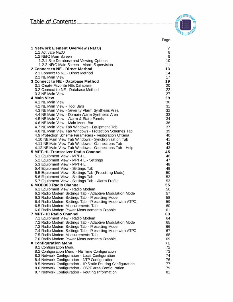
Copyright © 2012 Alcatel-Lucent. All Rights Reserved.TWT42013-6 Edition 3.03
9500 MPR (Microwave Packet Radio) · Operations & Maintenance R3.03 (ANSI)NE Operation · Operator GUI Interface4 · 1 · 5
COPYRIGHT © ALCATEL-LUCENT 2012. ALL RIGHTS RESERVED.
Table of Contents
Switch to notes view! Page
1 Network Element Overview (NEtO) 71.1 Activate NEtO 81.2 NEtO Main Screen 9
1.2.1 Site Database and Viewing Options 101.2.2 NEtO Main Screen - Alarm Supervision 11
2 Connect to NE - Direct Method 132.1 Connect to NE - Direct Method 142.2 NE Main View 17
3 Connect to NE - Database Method 193.1 Create Favorite NEs Database 203.2 Connect to NE - Database Method 223.3 NE Main View 27
4 Main View 294.1 NE Main View 304.2 NE Main View - Tool Bars 314.3 NE Main View - Severity Alarm Synthesis Area 324.4 NE Main View - Domain Alarm Synthesis Area 334.5 NE Main View - Alarm & State Panels 344.6 NE Main View - Main Menu Bar 364.7 NE Main View Tab Windows - Equipment Tab 374.8 NE Main View Tab Windows - Protection Schemes Tab 394.9 Protection Scheme Parameters - Restoration Criteria 404.10 NE Main View Tab Windows - Synchronization Tab 414.11 NE Main View Tab Windows - Connections Tab 424.12 NE Main View Tab Windows - Connections Tab - Help 43
5 MPT-HL Transceiver Radio Channel 455.1 Equipment View - MPT-HL 465.2 Equipment View - MPT-HL - Settings 475.3 Equipment View - MPT-HL 485.4 Equipment View - Settings Tab 495.5 Equipment View - Settings Tab (Presetting Mode) 505.6 Equipment View - Settings Tab 525.7 Equipment View - Settings Tab - Alarm Profile 53
6 MOD300 Radio Channel 556.1 Equipment View - Radio Modem 566.2 Radio Modem Settings Tab - Adaptive Modulation Mode 576.3 Radio Modem Settings Tab - Presetting Mode 586.4 Radio Modem Settings Tab - Presetting Mode with ATPC 596.5 Radio Modem Measurements Tab 606.6 Radio Modem Power Measurements Graphic 61
7 MPT-HC Radio Channel 637.1 Equipment View - Radio Modem 647.2 Radio Modem Settings Tab - Adaptive Modulation Mode 657.3 Radio Modem Settings Tab - Presetting Mode 667.4 Radio Modem Settings Tab - Presetting Mode with ATPC 677.5 Radio Modem Measurements Tab 687.6 Radio Modem Power Measurements Graphic 69
8 Configuration Menu 718.1 Configuration Menu 728.2 Configuration Menu - NE Time Configuration 738.3 Network Configuration - Local Configuration 748.4 Network Configuration - NTP Configuration 768.5 Network Configuration - IP Static Routing Configuration 778.6 Network Configuration - OSPF Area Configuration 798.7 Network Configuration - Routing Information 81
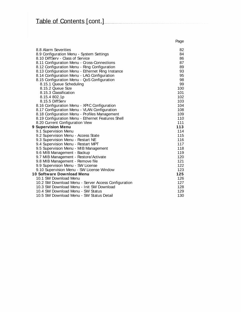
Copyright © 2012 Alcatel-Lucent. All Rights Reserved.TWT42013-6 Edition 3.03
9500 MPR (Microwave Packet Radio) · Operations & Maintenance R3.03 (ANSI)NE Operation · Operator GUI Interface4 · 1 · 6
COPYRIGHT © ALCATEL-LUCENT 2012. ALL RIGHTS RESERVED.
Table of Contents [cont.]
Switch to notes view! Page
8.8 Alarm Severities 828.9 Configuration Menu - System Settings 848.10 DiffServ - Class of Service 868.11 Configuration Menu - Cross-Connections 878.12 Configuration Menu - Ring Configuration 898.13 Configuration Menu - Ethernet Ring Instance 938.14 Configuration Menu - LAG Configuration 958.15 Configuration Menu - QoS Configuration 98
8.15.1 Queue Scheduling 998.15.2 Queue Size 1008.15.3 Classification 1018.15.4 802.1p 1028.15.5 DiffServ 103
8.16 Configuration Menu - XPIC Configuration 1048.17 Configuration Menu - VLAN Configuration 1088.18 Configuration Menu - Profiles Management 1098.19 Configuration Menu - Ethernet Features Shell 1108.20 Current Configuration View 111
9 Supervision Menu 1139.1 Supervision Menu 1149.2 Supervision Menu - Access State 1159.3 Supervision Menu - Restart NE 1169.4 Supervision Menu - Restart MPT 1179.5 Supervision Menu - MIB Management 1189.6 MIB Management - Backup 1199.7 MIB Management - Restore/Activate 1209.8 MIB Management - Remove file 1219.9 Supervision Menu - SW License 1229.10 Supervision Menu - SW License Window 123
10 Software Download Menu 12510.1 SW Download Menu 12610.2 SW Download Menu - Server Access Configuration 12710.3 SW Download Menu - Init SW Download 12810.4 SW Download Menu - SW Status 12910.5 SW Download Menu - SW Status Detail 130

Copyright © 2012 Alcatel-Lucent. All Rights Reserved.TWT42013-6 Edition 3.03
Section 4 · Module 1 · Page 7
9500 MPR (Microwave Packet Radio) · Operations & Maintenance R3.03 (ANSI)NE Operation · Operator GUI Interface4 · 1 · 7
COPYRIGHT © ALCATEL-LUCENT 2012. ALL RIGHTS RESERVED.
1 Network Element Overview (NEtO)
Refer to 9500 MPR Operation and Administration, 3EM23954AHAA, DLP-100 for more details
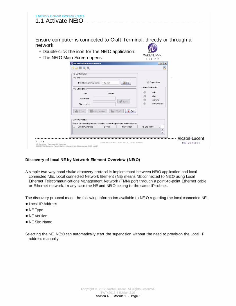
Copyright © 2012 Alcatel-Lucent. All Rights Reserved.TWT42013-6 Edition 3.03
Section 4 · Module 1 · Page 8Section 4 · Module 1 · Page 8
9500 MPR (Microwave Packet Radio) · Operations & Maintenance R3.03 (ANSI)NE Operation · Operator GUI Interface4 · 1 · 8
COPYRIGHT © ALCATEL-LUCENT 2012. ALL RIGHTS RESERVED.
Ensure computer is connected to Craft Terminal, directly or through a network
Double-click the icon for the NEtO application:The NEtO Main Screen opens:
1 Network Element Overview (NEtO)
1.1 Activate NEtO
Discovery of local NE by Network Element Overview (NEtO)
A simple two-way hand shake discovery protocol is implemented between NEtO application and local connected NEs. Local connected Network Element (NE) means NE connected to NEtO using Local Ethernet Telecommunications Management Network (TMN) port through a point-to-point Ethernet cable or Ethernet network. In any case the NE and NEtO belong to the same IP subnet.
The discovery protocol made the following information available to NEtO regarding the local connected NE:
Local IP Address
NE Type
NE Version
NE Site Name
Selecting the NE, NEtO can automatically start the supervision without the need to provision the Local IP address manually.
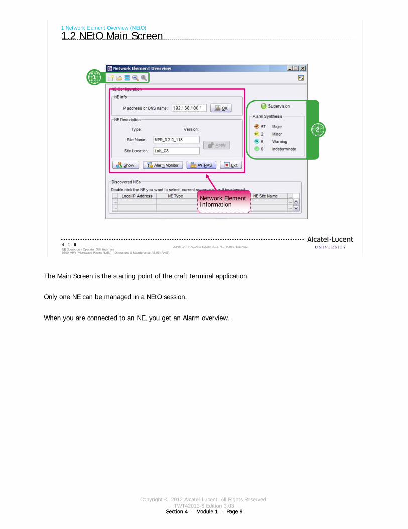
Copyright © 2012 Alcatel-Lucent. All Rights Reserved.TWT42013-6 Edition 3.03
Section 4 · Module 1 · Page 9Section 4 · Module 1 · Page 9
9500 MPR (Microwave Packet Radio) · Operations & Maintenance R3.03 (ANSI)NE Operation · Operator GUI Interface4 · 1 · 9
COPYRIGHT © ALCATEL-LUCENT 2012. ALL RIGHTS RESERVED.
1 Network Element Overview (NEtO)
1.2 NEtO Main Screen
2
1
Network Element Information
The Main Screen is the starting point of the craft terminal application.
Only one NE can be managed in a NEtO session.
When you are connected to an NE, you get an Alarm overview.
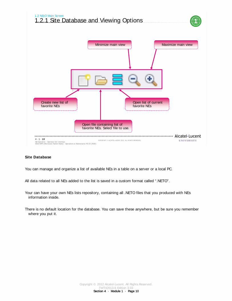
Copyright © 2012 Alcatel-Lucent. All Rights Reserved.TWT42013-6 Edition 3.03
Section 4 · Module 1 · Page 10Section 4 · Module 1 · Page 10
9500 MPR (Microwave Packet Radio) · Operations & Maintenance R3.03 (ANSI)NE Operation · Operator GUI Interface4 · 1 · 10
COPYRIGHT © ALCATEL-LUCENT 2012. ALL RIGHTS RESERVED.
1.2 NEtO Main Screen
1.2.1 Site Database and Viewing Options 1
Minimize main view Maximize main view
Create new list of favorite NEs
Open list of current favorite NEs
Open file containing list of favorite NEs. Select file to use.
Site Database
You can manage and organize a list of available NEs in a table on a server or a local PC.
All data related to all NEs added to the list is saved in a custom format called “.NETO”.
Your can have your own NEs lists repository, containing all .NETO files that you produced with NEs information inside.
There is no default location for the database. You can save these anywhere, but be sure you remember where you put it.
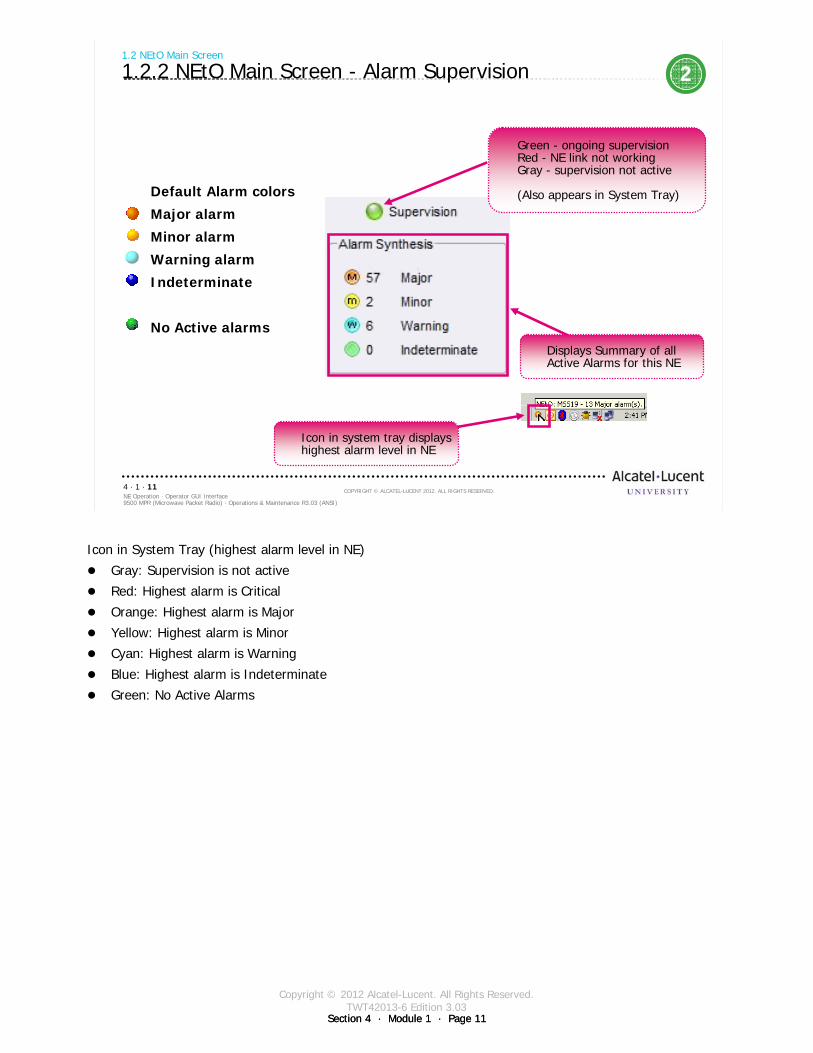
Copyright © 2012 Alcatel-Lucent. All Rights Reserved.TWT42013-6 Edition 3.03
Section 4 · Module 1 · Page 11Section 4 · Module 1 · Page 11
9500 MPR (Microwave Packet Radio) · Operations & Maintenance R3.03 (ANSI)NE Operation · Operator GUI Interface4 · 1 · 11
COPYRIGHT © ALCATEL-LUCENT 2012. ALL RIGHTS RESERVED.
1.2 NEtO Main Screen
1.2.2 NEtO Main Screen - Alarm Supervision
Default Alarm colors
Major alarm
Minor alarm
Warning alarm
Indeterminate
No Active alarms
2
Green - ongoing supervisionRed - NE link not workingGray - supervision not active
(Also appears in System Tray)
Displays Summary of all Active Alarms for this NE
Icon in system tray displays highest alarm level in NE
Icon in System Tray (highest alarm level in NE)
Gray: Supervision is not active
Red: Highest alarm is Critical
Orange: Highest alarm is Major
Yellow: Highest alarm is Minor
Cyan: Highest alarm is Warning
Blue: Highest alarm is Indeterminate
Green: No Active Alarms

Copyright © 2012 Alcatel-Lucent. All Rights Reserved.TWT42013-6 Edition 3.03
Section 4 · Module 1 · Page 12Section 4 · Module 1 · Page 12
9500 MPR (Microwave Packet Radio) · Operations & Maintenance R3.03 (ANSI)NE Operation · Operator GUI Interface4 · 1 · 12
COPYRIGHT © ALCATEL-LUCENT 2012. ALL RIGHTS RESERVED.
Blank page
Switch to notes view!
This page intentionally left blank

Copyright © 2012 Alcatel-Lucent. All Rights Reserved.TWT42013-6 Edition 3.03
Section 4 · Module 1 · Page 13
9500 MPR (Microwave Packet Radio) · Operations & Maintenance R3.03 (ANSI)NE Operation · Operator GUI Interface4 · 1 · 13
COPYRIGHT © ALCATEL-LUCENT 2012. ALL RIGHTS RESERVED.
2 Connect to NE - Direct Method
Refer to 9500 MPR Operation and Administration, 3EM23954AHAA, DLP-100 for more details
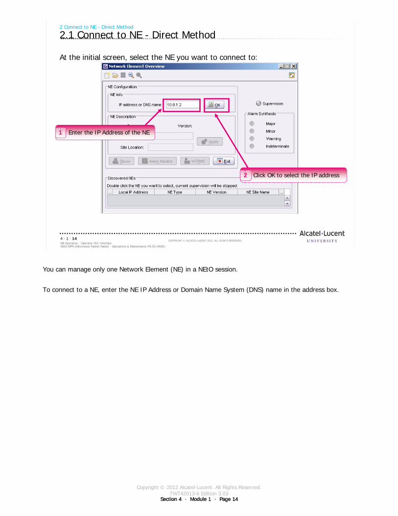
Copyright © 2012 Alcatel-Lucent. All Rights Reserved.TWT42013-6 Edition 3.03
Section 4 · Module 1 · Page 14Section 4 · Module 1 · Page 14
9500 MPR (Microwave Packet Radio) · Operations & Maintenance R3.03 (ANSI)NE Operation · Operator GUI Interface4 · 1 · 14
COPYRIGHT © ALCATEL-LUCENT 2012. ALL RIGHTS RESERVED.
2 Connect to NE - Direct Method
2.1 Connect to NE - Direct Method
At the initial screen, select the NE you want to connect to:
Enter the IP Address of the NE1
Click OK to select the IP address2
You can manage only one Network Element (NE) in a NEtO session.
To connect to a NE, enter the NE IP Address or Domain Name System (DNS) name in the address box.
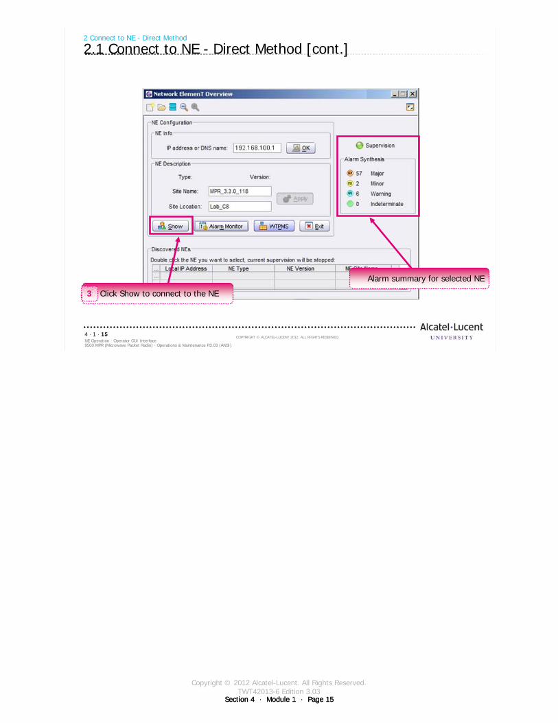
Copyright © 2012 Alcatel-Lucent. All Rights Reserved.TWT42013-6 Edition 3.03
Section 4 · Module 1 · Page 15Section 4 · Module 1 · Page 15
9500 MPR (Microwave Packet Radio) · Operations & Maintenance R3.03 (ANSI)NE Operation · Operator GUI Interface4 · 1 · 15
COPYRIGHT © ALCATEL-LUCENT 2012. ALL RIGHTS RESERVED.
2 Connect to NE - Direct Method
2.1 Connect to NE - Direct Method [cont.]
Click Show to connect to the NE3
Alarm summary for selected NE

Copyright © 2012 Alcatel-Lucent. All Rights Reserved.TWT42013-6 Edition 3.03
Section 4 · Module 1 · Page 16Section 4 · Module 1 · Page 16
9500 MPR (Microwave Packet Radio) · Operations & Maintenance R3.03 (ANSI)NE Operation · Operator GUI Interface4 · 1 · 16
COPYRIGHT © ALCATEL-LUCENT 2012. ALL RIGHTS RESERVED.
2 Connect to NE - Direct Method
2.1 Connect to NE - Direct Method [cont.]
Enter username4
Enter login password5
Click Login6
Login
Type your username - must not be more than 20 characters.
Type your password - must not be less than eight (8) or more than 20 characters and must be composed of ASCII characters set (UPPER/lower case, numeric and special characters).
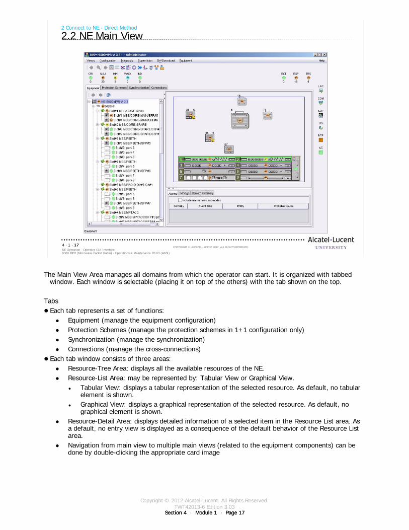
Copyright © 2012 Alcatel-Lucent. All Rights Reserved.TWT42013-6 Edition 3.03
Section 4 · Module 1 · Page 17Section 4 · Module 1 · Page 17
9500 MPR (Microwave Packet Radio) · Operations & Maintenance R3.03 (ANSI)NE Operation · Operator GUI Interface4 · 1 · 17
COPYRIGHT © ALCATEL-LUCENT 2012. ALL RIGHTS RESERVED.
2 Connect to NE - Direct Method
2.2 NE Main View
The Main View Area manages all domains from which the operator can start. It is organized with tabbed window. Each window is selectable (placing it on top of the others) with the tab shown on the top.
TabsEach tab represents a set of functions:
Equipment (manage the equipment configuration)Protection Schemes (manage the protection schemes in 1+1 configuration only)Synchronization (manage the synchronization)Connections (manage the cross-connections)
Each tab window consists of three areas:Resource-Tree Area: displays all the available resources of the NE.Resource-List Area: may be represented by: Tabular View or Graphical View.
Tabular View: displays a tabular representation of the selected resource. As default, no tabular element is shown.Graphical View: displays a graphical representation of the selected resource. As default, no graphical element is shown.
Resource-Detail Area: displays detailed information of a selected item in the Resource List area. As a default, no entry view is displayed as a consequence of the default behavior of the Resource List area.Navigation from main view to multiple main views (related to the equipment components) can be done by double-clicking the appropriate card image

Copyright © 2012 Alcatel-Lucent. All Rights Reserved.TWT42013-6 Edition 3.03
Section 4 · Module 1 · Page 18Section 4 · Module 1 · Page 18
9500 MPR (Microwave Packet Radio) · Operations & Maintenance R3.03 (ANSI)NE Operation · Operator GUI Interface4 · 1 · 18
COPYRIGHT © ALCATEL-LUCENT 2012. ALL RIGHTS RESERVED.
Blank page
Switch to notes view!
This page intentionally left blank

Copyright © 2012 Alcatel-Lucent. All Rights Reserved.TWT42013-6 Edition 3.03
Section 4 · Module 1 · Page 19
9500 MPR (Microwave Packet Radio) · Operations & Maintenance R3.03 (ANSI)NE Operation · Operator GUI Interface4 · 1 · 19
COPYRIGHT © ALCATEL-LUCENT 2012. ALL RIGHTS RESERVED.
3 Connect to NE - Database Method
Refer to 9500 MPR Operation and Administration, 3EM23954AHAA, DLP-127 for more details
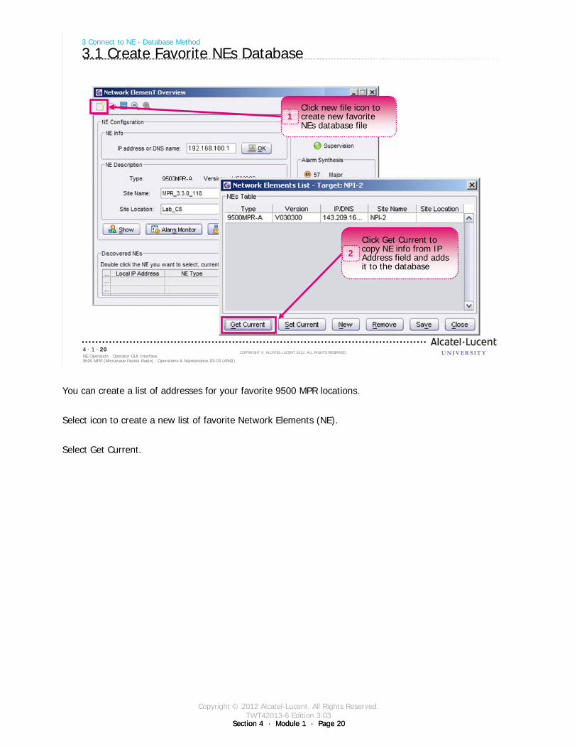
Copyright © 2012 Alcatel-Lucent. All Rights Reserved.TWT42013-6 Edition 3.03
Section 4 · Module 1 · Page 20Section 4 · Module 1 · Page 20
9500 MPR (Microwave Packet Radio) · Operations & Maintenance R3.03 (ANSI)NE Operation · Operator GUI Interface4 · 1 · 20
COPYRIGHT © ALCATEL-LUCENT 2012. ALL RIGHTS RESERVED.
3 Connect to NE - Database Method
3.1 Create Favorite NEs Database
Click new file icon to create new favorite NEs database file
1
Click Get Current to copy NE info from IP Address field and adds it to the database
2
You can create a list of addresses for your favorite 9500 MPR locations.
Select icon to create a new list of favorite Network Elements (NE).
Select Get Current.
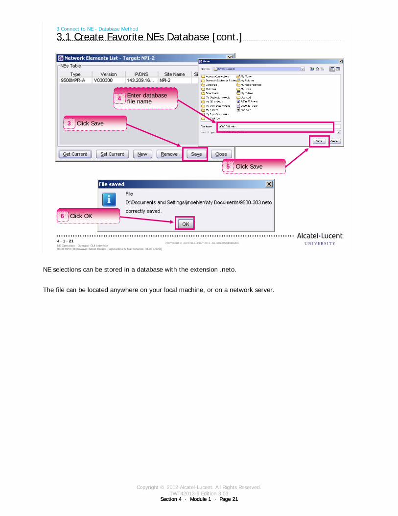
Copyright © 2012 Alcatel-Lucent. All Rights Reserved.TWT42013-6 Edition 3.03
Section 4 · Module 1 · Page 21Section 4 · Module 1 · Page 21
9500 MPR (Microwave Packet Radio) · Operations & Maintenance R3.03 (ANSI)NE Operation · Operator GUI Interface4 · 1 · 21
COPYRIGHT © ALCATEL-LUCENT 2012. ALL RIGHTS RESERVED.
3 Connect to NE - Database Method
3.1 Create Favorite NEs Database [cont.]
Click Save3
Enter database file name4
Click Save5
Click OK6
NE selections can be stored in a database with the extension .neto.
The file can be located anywhere on your local machine, or on a network server.
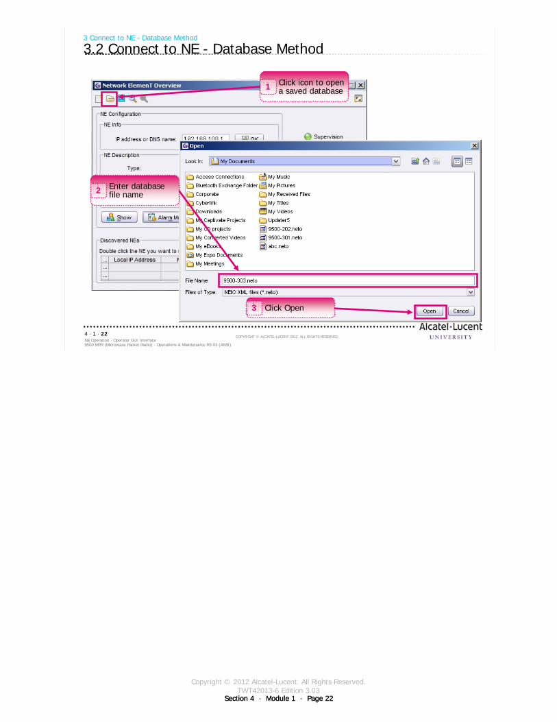
Copyright © 2012 Alcatel-Lucent. All Rights Reserved.TWT42013-6 Edition 3.03
Section 4 · Module 1 · Page 22Section 4 · Module 1 · Page 22
9500 MPR (Microwave Packet Radio) · Operations & Maintenance R3.03 (ANSI)NE Operation · Operator GUI Interface4 · 1 · 22
COPYRIGHT © ALCATEL-LUCENT 2012. ALL RIGHTS RESERVED.
3 Connect to NE - Database Method
3.2 Connect to NE - Database Method
Click Open3
Enter database file name2
Click icon to open a saved database1
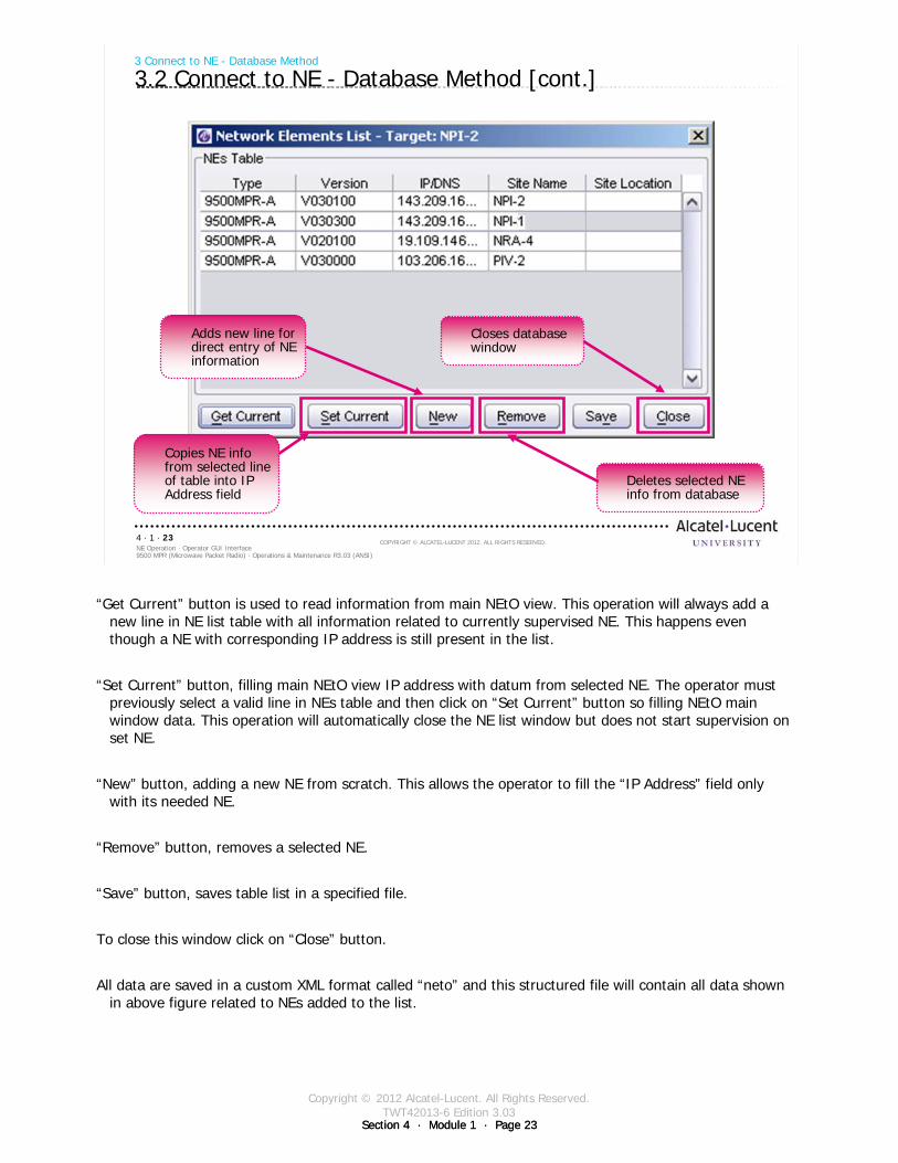
Copyright © 2012 Alcatel-Lucent. All Rights Reserved.TWT42013-6 Edition 3.03
Section 4 · Module 1 · Page 23Section 4 · Module 1 · Page 23
9500 MPR (Microwave Packet Radio) · Operations & Maintenance R3.03 (ANSI)NE Operation · Operator GUI Interface4 · 1 · 23
COPYRIGHT © ALCATEL-LUCENT 2012. ALL RIGHTS RESERVED.
3 Connect to NE - Database Method
3.2 Connect to NE - Database Method [cont.]
Adds new line for direct entry of NE information
Copies NE info from selected line of table into IP Address field
Closes database window
Deletes selected NE info from database
“Get Current” button is used to read information from main NEtO view. This operation will always add a new line in NE list table with all information related to currently supervised NE. This happens even though a NE with corresponding IP address is still present in the list.
“Set Current” button, filling main NEtO view IP address with datum from selected NE. The operator must previously select a valid line in NEs table and then click on “Set Current” button so filling NEtO main window data. This operation will automatically close the NE list window but does not start supervision on set NE.
“New” button, adding a new NE from scratch. This allows the operator to fill the “IP Address” field only with its needed NE.
“Remove” button, removes a selected NE.
“Save” button, saves table list in a specified file.
To close this window click on “Close” button.
All data are saved in a custom XML format called “neto” and this structured file will contain all data shown in above figure related to NEs added to the list.
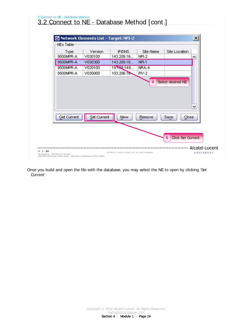
Copyright © 2012 Alcatel-Lucent. All Rights Reserved.TWT42013-6 Edition 3.03
Section 4 · Module 1 · Page 24Section 4 · Module 1 · Page 24
9500 MPR (Microwave Packet Radio) · Operations & Maintenance R3.03 (ANSI)NE Operation · Operator GUI Interface4 · 1 · 24
COPYRIGHT © ALCATEL-LUCENT 2012. ALL RIGHTS RESERVED.
3 Connect to NE - Database Method
3.2 Connect to NE - Database Method [cont.]
Click Set Current5
Select desired NE4
Once you build and open the file with the database, you may select the NE to open by clicking ‘Set Current’.

Copyright © 2012 Alcatel-Lucent. All Rights Reserved.TWT42013-6 Edition 3.03
Section 4 · Module 1 · Page 25Section 4 · Module 1 · Page 25
9500 MPR (Microwave Packet Radio) · Operations & Maintenance R3.03 (ANSI)NE Operation · Operator GUI Interface4 · 1 · 25
COPYRIGHT © ALCATEL-LUCENT 2012. ALL RIGHTS RESERVED.
3 Connect to NE - Database Method
3.2 Connect to NE - Database Method [cont.]
Selected NE IP address
Click OK to select IP address6
Click Show to connect to the NE7
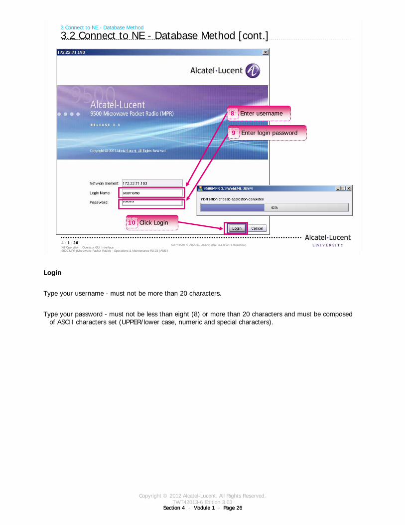
Copyright © 2012 Alcatel-Lucent. All Rights Reserved.TWT42013-6 Edition 3.03
Section 4 · Module 1 · Page 26Section 4 · Module 1 · Page 26
9500 MPR (Microwave Packet Radio) · Operations & Maintenance R3.03 (ANSI)NE Operation · Operator GUI Interface4 · 1 · 26
COPYRIGHT © ALCATEL-LUCENT 2012. ALL RIGHTS RESERVED.
3 Connect to NE - Database Method
3.2 Connect to NE - Database Method [cont.]
Enter username8
Enter login password9
Click Login10
Login
Type your username - must not be more than 20 characters.
Type your password - must not be less than eight (8) or more than 20 characters and must be composed of ASCII characters set (UPPER/lower case, numeric and special characters).
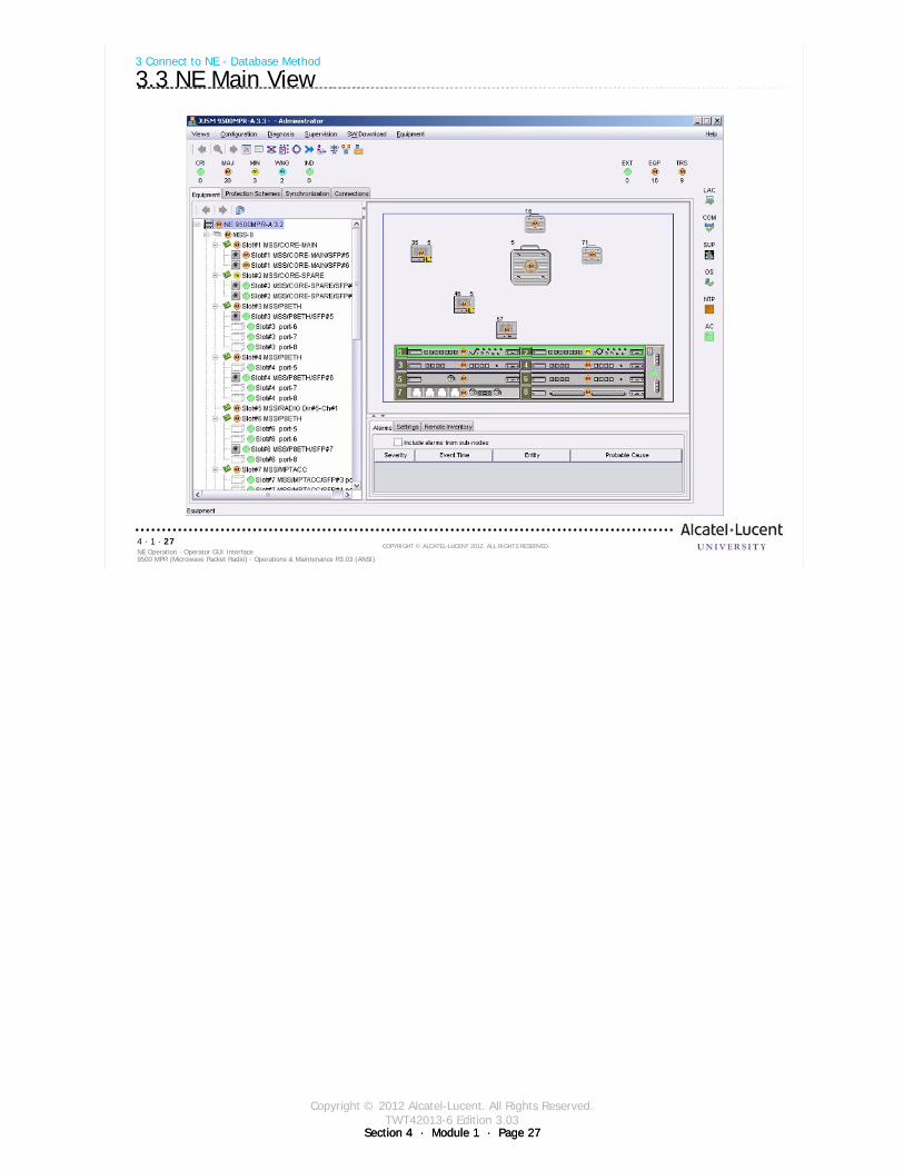
Copyright © 2012 Alcatel-Lucent. All Rights Reserved.TWT42013-6 Edition 3.03
Section 4 · Module 1 · Page 27Section 4 · Module 1 · Page 27
9500 MPR (Microwave Packet Radio) · Operations & Maintenance R3.03 (ANSI)NE Operation · Operator GUI Interface4 · 1 · 27
COPYRIGHT © ALCATEL-LUCENT 2012. ALL RIGHTS RESERVED.
3 Connect to NE - Database Method
3.3 NE Main View

Copyright © 2012 Alcatel-Lucent. All Rights Reserved.TWT42013-6 Edition 3.03
Section 4 · Module 1 · Page 28Section 4 · Module 1 · Page 28
9500 MPR (Microwave Packet Radio) · Operations & Maintenance R3.03 (ANSI)NE Operation · Operator GUI Interface4 · 1 · 28
COPYRIGHT © ALCATEL-LUCENT 2012. ALL RIGHTS RESERVED.
Blank page
Switch to notes view!
This page intentionally left blank

Copyright © 2012 Alcatel-Lucent. All Rights Reserved.TWT42013-6 Edition 3.03
Section 4 · Module 1 · Page 29
9500 MPR (Microwave Packet Radio) · Operations & Maintenance R3.03 (ANSI)NE Operation · Operator GUI Interface4 · 1 · 29
COPYRIGHT © ALCATEL-LUCENT 2012. ALL RIGHTS RESERVED.
4 Main View
Refer to 9500 MPR Operation and Administration, 3EM23954AHAA, WebEML Craft Terminal Reference
Guide for more details
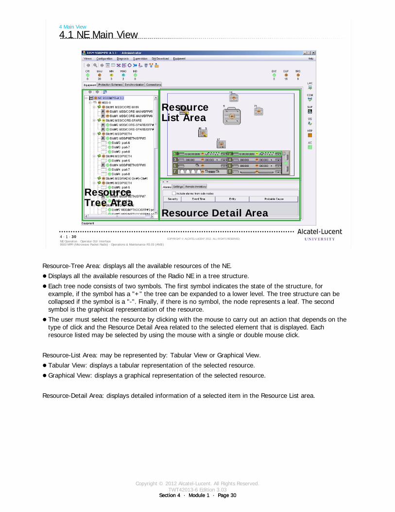
Copyright © 2012 Alcatel-Lucent. All Rights Reserved.TWT42013-6 Edition 3.03
Section 4 · Module 1 · Page 30Section 4 · Module 1 · Page 30
9500 MPR (Microwave Packet Radio) · Operations & Maintenance R3.03 (ANSI)NE Operation · Operator GUI Interface4 · 1 · 30
COPYRIGHT © ALCATEL-LUCENT 2012. ALL RIGHTS RESERVED.
4 Main View
4.1 NE Main View
ResourceTree Area
ResourceList Area
Resource Detail Area
Resource-Tree Area: displays all the available resources of the NE.
Displays all the available resources of the Radio NE in a tree structure.
Each tree node consists of two symbols. The first symbol indicates the state of the structure, for example, if the symbol has a "+" the tree can be expanded to a lower level. The tree structure can be collapsed if the symbol is a "-". Finally, if there is no symbol, the node represents a leaf. The second symbol is the graphical representation of the resource.
The user must select the resource by clicking with the mouse to carry out an action that depends on the type of click and the Resource Detail Area related to the selected element that is displayed. Each resource listed may be selected by using the mouse with a single or double mouse click.
Resource-List Area: may be represented by: Tabular View or Graphical View.
Tabular View: displays a tabular representation of the selected resource.
Graphical View: displays a graphical representation of the selected resource.
Resource-Detail Area: displays detailed information of a selected item in the Resource List area.
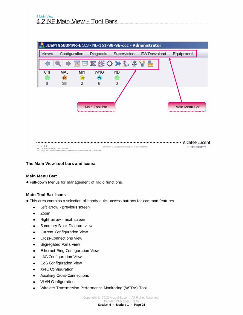
Copyright © 2012 Alcatel-Lucent. All Rights Reserved.TWT42013-6 Edition 3.03
Section 4 · Module 1 · Page 31Section 4 · Module 1 · Page 31
9500 MPR (Microwave Packet Radio) · Operations & Maintenance R3.03 (ANSI)NE Operation · Operator GUI Interface4 · 1 · 31
COPYRIGHT © ALCATEL-LUCENT 2012. ALL RIGHTS RESERVED.
4 Main View
4.2 NE Main View - Tool Bars
Main Menu BarMain Tool Bar
The Main View tool bars and icons:
Main Menu Bar:Pull-down Menus for management of radio functions.
Main Tool Bar Icons:
This area contains a selection of handy quick-access buttons for common features.
Left arrow - previous screen
Zoom
Right arrow - next screen
Summary Block Diagram view
Current Configuration View
Cross-Connections View
Segregated Ports View
Ethernet Ring Configuration View
LAG Configuration View
QoS Configuration View
XPIC Configuration
Auxiliary Cross-Connections
VLAN Configuration
Wireless Transmission Performance Monitoring (WTPM) Tool
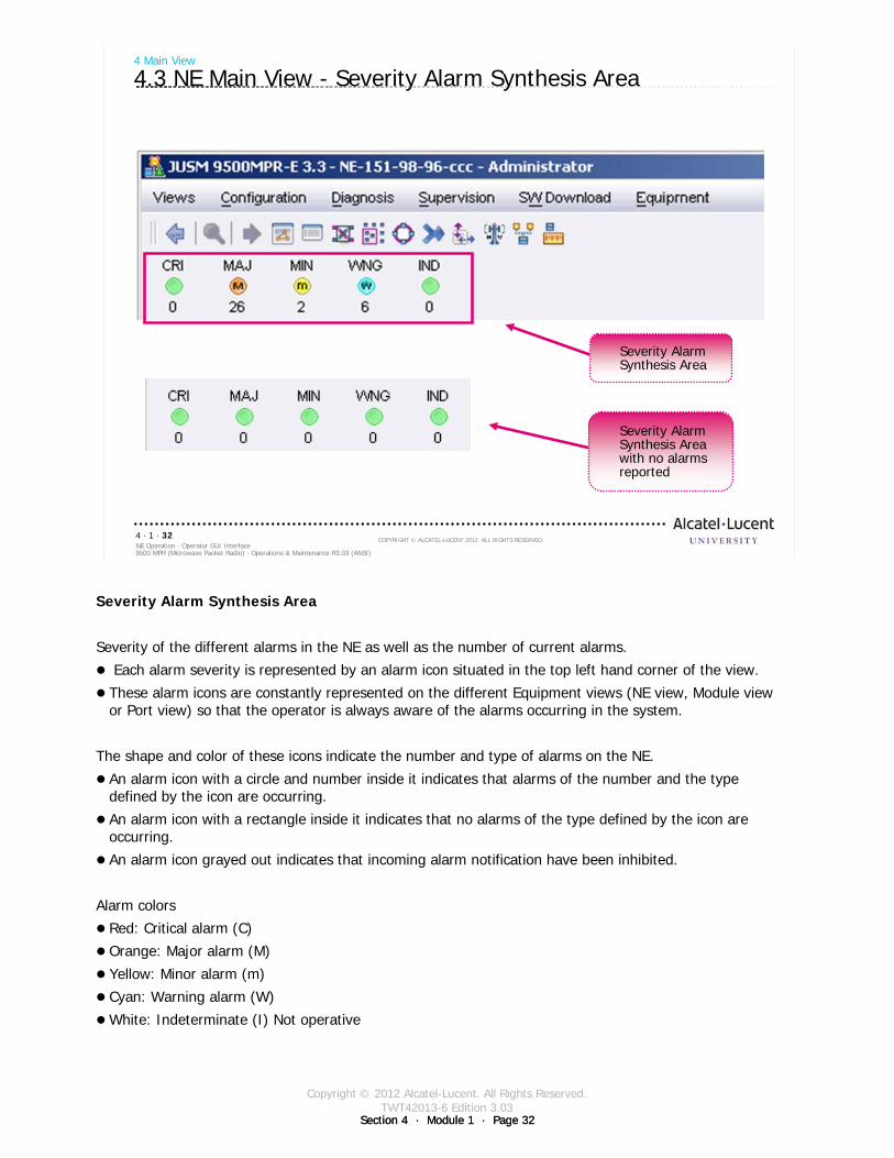
Copyright © 2012 Alcatel-Lucent. All Rights Reserved.TWT42013-6 Edition 3.03
Section 4 · Module 1 · Page 32Section 4 · Module 1 · Page 32
9500 MPR (Microwave Packet Radio) · Operations & Maintenance R3.03 (ANSI)NE Operation · Operator GUI Interface4 · 1 · 32
COPYRIGHT © ALCATEL-LUCENT 2012. ALL RIGHTS RESERVED.
4 Main View
4.3 NE Main View - Severity Alarm Synthesis Area
Severity Alarm Synthesis Area
Severity Alarm Synthesis Area with no alarms reported
Severity Alarm Synthesis Area
Severity of the different alarms in the NE as well as the number of current alarms.
Each alarm severity is represented by an alarm icon situated in the top left hand corner of the view.
These alarm icons are constantly represented on the different Equipment views (NE view, Module view or Port view) so that the operator is always aware of the alarms occurring in the system.
The shape and color of these icons indicate the number and type of alarms on the NE.
An alarm icon with a circle and number inside it indicates that alarms of the number and the type defined by the icon are occurring.
An alarm icon with a rectangle inside it indicates that no alarms of the type defined by the icon are occurring.
An alarm icon grayed out indicates that incoming alarm notification have been inhibited.
Alarm colors
Red: Critical alarm (C)
Orange: Major alarm (M)
Yellow: Minor alarm (m)
Cyan: Warning alarm (W)
White: Indeterminate (I) Not operative
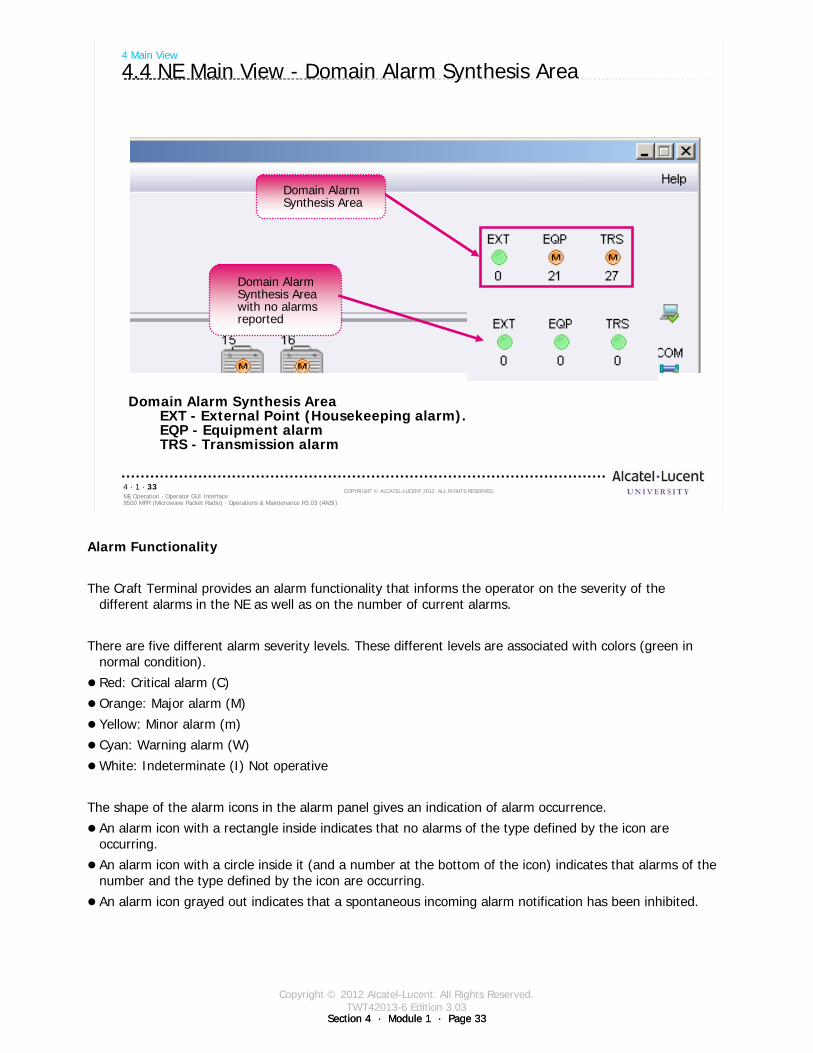
Copyright © 2012 Alcatel-Lucent. All Rights Reserved.TWT42013-6 Edition 3.03
Section 4 · Module 1 · Page 33Section 4 · Module 1 · Page 33
9500 MPR (Microwave Packet Radio) · Operations & Maintenance R3.03 (ANSI)NE Operation · Operator GUI Interface4 · 1 · 33
COPYRIGHT © ALCATEL-LUCENT 2012. ALL RIGHTS RESERVED.
Domain Alarm Synthesis AreaEXT - External Point (Housekeeping alarm). EQP - Equipment alarmTRS - Transmission alarm
4 Main View
4.4 NE Main View - Domain Alarm Synthesis Area
Domain Alarm Synthesis Area
Domain Alarm Synthesis Area with no alarms reported
Alarm Functionality
The Craft Terminal provides an alarm functionality that informs the operator on the severity of the different alarms in the NE as well as on the number of current alarms.
There are five different alarm severity levels. These different levels are associated with colors (green in normal condition).
Red: Critical alarm (C)
Orange: Major alarm (M)
Yellow: Minor alarm (m)
Cyan: Warning alarm (W)
White: Indeterminate (I) Not operative
The shape of the alarm icons in the alarm panel gives an indication of alarm occurrence.
An alarm icon with a rectangle inside indicates that no alarms of the type defined by the icon are occurring.
An alarm icon with a circle inside it (and a number at the bottom of the icon) indicates that alarms of the number and the type defined by the icon are occurring.
An alarm icon grayed out indicates that a spontaneous incoming alarm notification has been inhibited.
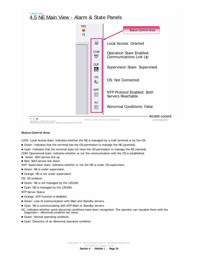
Copyright © 2012 Alcatel-Lucent. All Rights Reserved.TWT42013-6 Edition 3.03
Section 4 · Module 1 · Page 34Section 4 · Module 1 · Page 34
9500 MPR (Microwave Packet Radio) · Operations & Maintenance R3.03 (ANSI)NE Operation · Operator GUI Interface4 · 1 · 34
COPYRIGHT © ALCATEL-LUCENT 2012. ALL RIGHTS RESERVED.
4 Main View
4.5 NE Main View - Alarm & State Panels
Local Access: Granted
Operation State Enabled: Communications Link Up
Supervision State: Supervised
OS: Not Connected
NTP Protocol Enabled: Both Servers Reachable
Abnormal Conditions: False
Status Control Area
Status Control Area
LOCK: Local Access state: indicates whether the NE is managed by a craft terminal or by the OS.Green: Indicates that the terminal has the OS permission to manage the NE (granted).
Cyan: Indicates that the terminal does not have the OS permission to manage the NE (denied).COM: Operational state: indicates whether or not the communication with the OS is established.
Green: SDH service link upRed: SDH service link down
SUP: Supervision state: indicates whether or not the NE is under OS supervision. Green: NE is under supervision.
Orange: NE is not under supervision.
OS: OS isolation.
Green: NE is not managed by the 1353SH.
Cyan: NE is managed by the 1353SH.
NTP Server Status
Orange: NTP function is disabled.
Green: Loss of communication with Main and Standby servers.
Cyan: NE is communicating with NTP Main or Standby servers.AC: Indicates whether some abnormal conditions have been recognized. The operator can visualize them with the
Diagnosis-> Abnormal condition list menu.Green: Normal operating condition
Cyan: Detection of an Abnormal operative condition
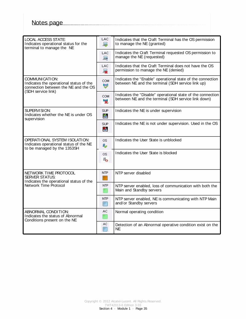
Copyright © 2012 Alcatel-Lucent. All Rights Reserved.TWT42013-6 Edition 3.03
Section 4 · Module 1 · Page 35
9500 MPR (Microwave Packet Radio) · Operations & Maintenance R3.03 (ANSI)NE Operation · Operator GUI Interface4 · 1 · 35
COPYRIGHT © ALCATEL-LUCENT 2012. ALL RIGHTS RESERVED.
Notes page
Switch to notes view!LOCAL ACCESS STATE: Indicates operational status for the terminal to manage the NE
Indicates that the Craft Terminal has the OS permission to manage the NE (granted)
Indicates the Craft Terminal requested OS permission to manage the NE (requested)
Indicates that the Craft Terminal does not have the OS permission to manage the NE (denied)
COMMUNICATION:Indicates the operational status of the connection between the NE and the OS (SDH service link)
Indicates the “Enable” operational state of the connection between NE and the terminal (SDH service link up)
Indicates the “Disable” operational state of the connection between NE and the terminal (SDH service link down)
SUPERVISION:Indicates whether the NE is under OS supervision
Indicates the NE is under supervision
Indicates the NE is not under supervision. Used in the OS
OPERATIONAL SYSTEM ISOLATION:Indicates operational status of the NE to be managed by the 1353SH
Indicates the User State is unblocked
Indicates the User State is blocked
NETWORK TIME PROTOCOL SERVER STATUS: Indicates the operational status of the Network Time Protocol
NTP server disabled
NTP server enabled, loss of communication with both the Main and Standby servers
NTP server enabled, NE is communicating with NTP Main and/or Standby servers
ABNORMAL CONDITION: Indicates the status of AbnormalConditions present on the NE
Normal operating condition
Detection of an Abnormal operative condition exist on the NE
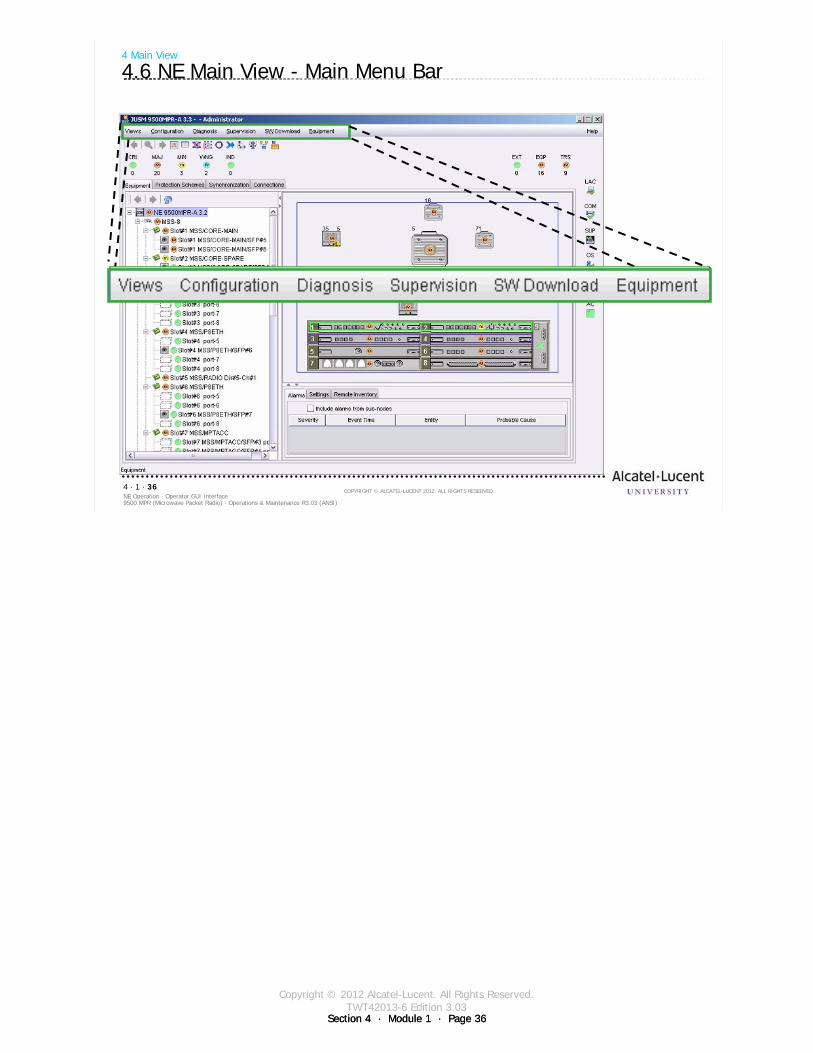
Copyright © 2012 Alcatel-Lucent. All Rights Reserved.TWT42013-6 Edition 3.03
Section 4 · Module 1 · Page 36Section 4 · Module 1 · Page 36
9500 MPR (Microwave Packet Radio) · Operations & Maintenance R3.03 (ANSI)NE Operation · Operator GUI Interface4 · 1 · 36
COPYRIGHT © ALCATEL-LUCENT 2012. ALL RIGHTS RESERVED.
4 Main View
4.6 NE Main View - Main Menu Bar
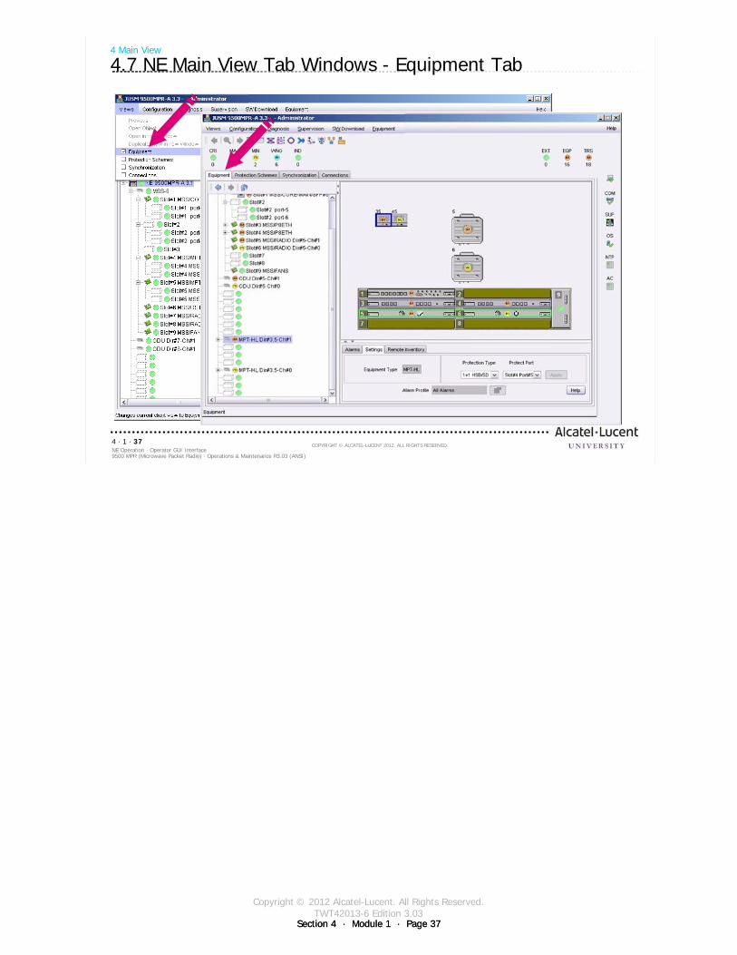
Copyright © 2012 Alcatel-Lucent. All Rights Reserved.TWT42013-6 Edition 3.03
Section 4 · Module 1 · Page 37Section 4 · Module 1 · Page 37
9500 MPR (Microwave Packet Radio) · Operations & Maintenance R3.03 (ANSI)NE Operation · Operator GUI Interface4 · 1 · 37
COPYRIGHT © ALCATEL-LUCENT 2012. ALL RIGHTS RESERVED.
4 Main View
4.7 NE Main View Tab Windows - Equipment Tab
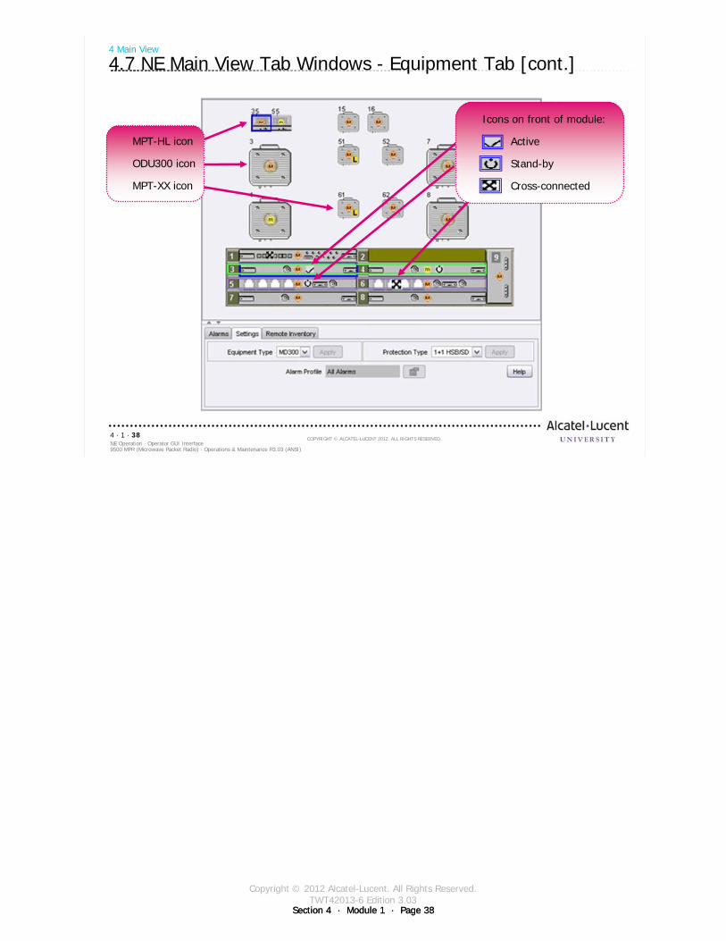
Copyright © 2012 Alcatel-Lucent. All Rights Reserved.TWT42013-6 Edition 3.03
Section 4 · Module 1 · Page 38Section 4 · Module 1 · Page 38
9500 MPR (Microwave Packet Radio) · Operations & Maintenance R3.03 (ANSI)NE Operation · Operator GUI Interface4 · 1 · 38
COPYRIGHT © ALCATEL-LUCENT 2012. ALL RIGHTS RESERVED.
4 Main View
4.7 NE Main View Tab Windows - Equipment Tab [cont.]
MPT-HL icon
ODU300 icon
MPT-XX icon
Icons on front of module:
Active
Stand-by
Cross-connected

Copyright © 2012 Alcatel-Lucent. All Rights Reserved.TWT42013-6 Edition 3.03
Section 4 · Module 1 · Page 39Section 4 · Module 1 · Page 39
9500 MPR (Microwave Packet Radio) · Operations & Maintenance R3.03 (ANSI)NE Operation · Operator GUI Interface4 · 1 · 39
COPYRIGHT © ALCATEL-LUCENT 2012. ALL RIGHTS RESERVED.
4 Main View
4.8 NE Main View Tab Windows - Protection Schemes Tab
Manual= switches between main and spareLockout= forces to main (Channel 1)Forced= forces to spare (Channel 0)
Equipment Protection Switching
Equipment protection is used to provide protection to a service implemented on one or several equipment.
Equipment protection is performed by switching the equipment supporting the protected service when this equipment fails to protection (or spare) equipment capable of supporting the same service.

Copyright © 2012 Alcatel-Lucent. All Rights Reserved.TWT42013-6 Edition 3.03
Section 4 · Module 1 · Page 40Section 4 · Module 1 · Page 40
9500 MPR (Microwave Packet Radio) · Operations & Maintenance R3.03 (ANSI)NE Operation · Operator GUI Interface4 · 1 · 40
COPYRIGHT © ALCATEL-LUCENT 2012. ALL RIGHTS RESERVED.
4 Main View
4.9 Protection Scheme Parameters - Restoration Criteria
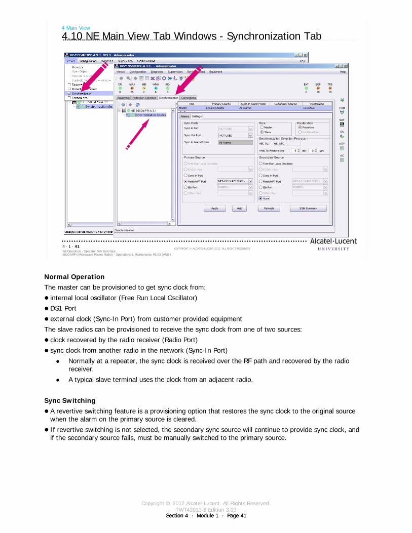
Copyright © 2012 Alcatel-Lucent. All Rights Reserved.TWT42013-6 Edition 3.03
Section 4 · Module 1 · Page 41Section 4 · Module 1 · Page 41
9500 MPR (Microwave Packet Radio) · Operations & Maintenance R3.03 (ANSI)NE Operation · Operator GUI Interface4 · 1 · 41
COPYRIGHT © ALCATEL-LUCENT 2012. ALL RIGHTS RESERVED.
4 Main View
4.10 NE Main View Tab Windows - Synchronization Tab
Normal OperationThe master can be provisioned to get sync clock from:
internal local oscillator (Free Run Local Oscillator)
DS1 Port
external clock (Sync-In Port) from customer provided equipment
The slave radios can be provisioned to receive the sync clock from one of two sources:
clock recovered by the radio receiver (Radio Port)
sync clock from another radio in the network (Sync-In Port)
Normally at a repeater, the sync clock is received over the RF path and recovered by the radio receiver.
A typical slave terminal uses the clock from an adjacent radio.
Sync Switching A revertive switching feature is a provisioning option that restores the sync clock to the original source when the alarm on the primary source is cleared.
If revertive switching is not selected, the secondary sync source will continue to provide sync clock, and if the secondary source fails, must be manually switched to the primary source.
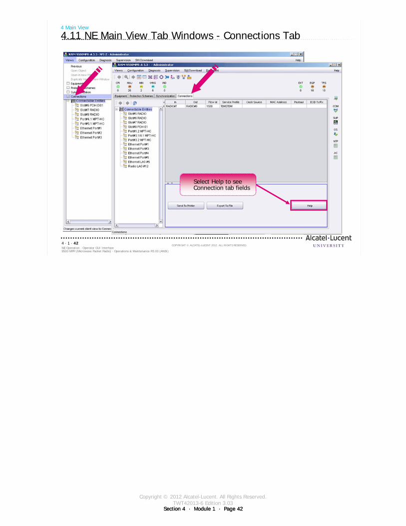
Copyright © 2012 Alcatel-Lucent. All Rights Reserved.TWT42013-6 Edition 3.03
Section 4 · Module 1 · Page 42Section 4 · Module 1 · Page 42
9500 MPR (Microwave Packet Radio) · Operations & Maintenance R3.03 (ANSI)NE Operation · Operator GUI Interface4 · 1 · 42
COPYRIGHT © ALCATEL-LUCENT 2012. ALL RIGHTS RESERVED.
4 Main View
4.11 NE Main View Tab Windows - Connections Tab
Select Help to see Connection tab fieldsSelect Help to see Connection tab fields
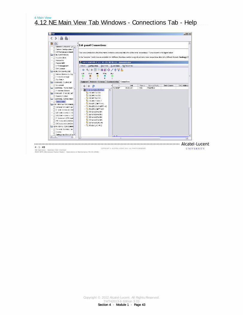
Copyright © 2012 Alcatel-Lucent. All Rights Reserved.TWT42013-6 Edition 3.03
Section 4 · Module 1 · Page 43Section 4 · Module 1 · Page 43
9500 MPR (Microwave Packet Radio) · Operations & Maintenance R3.03 (ANSI)NE Operation · Operator GUI Interface4 · 1 · 43
COPYRIGHT © ALCATEL-LUCENT 2012. ALL RIGHTS RESERVED.
4 Main View
4.12 NE Main View Tab Windows - Connections Tab - Help

Copyright © 2012 Alcatel-Lucent. All Rights Reserved.TWT42013-6 Edition 3.03
Section 4 · Module 1 · Page 44Section 4 · Module 1 · Page 44
9500 MPR (Microwave Packet Radio) · Operations & Maintenance R3.03 (ANSI)NE Operation · Operator GUI Interface4 · 1 · 44
COPYRIGHT © ALCATEL-LUCENT 2012. ALL RIGHTS RESERVED.
Blank page
Switch to notes view!
This page intentionally left blank

Copyright © 2012 Alcatel-Lucent. All Rights Reserved.TWT42013-6 Edition 3.03
Section 4 · Module 1 · Page 45
9500 MPR (Microwave Packet Radio) · Operations & Maintenance R3.03 (ANSI)NE Operation · Operator GUI Interface4 · 1 · 45
COPYRIGHT © ALCATEL-LUCENT 2012. ALL RIGHTS RESERVED.
5 MPT-HL Transceiver Radio Channel
Refer to 9500 MPR Operation and Administration, 3EM23954AHAA, DLP-109 for more details
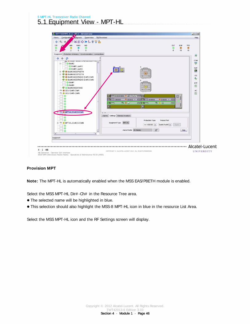
Copyright © 2012 Alcatel-Lucent. All Rights Reserved.TWT42013-6 Edition 3.03
Section 4 · Module 1 · Page 46Section 4 · Module 1 · Page 46
9500 MPR (Microwave Packet Radio) · Operations & Maintenance R3.03 (ANSI)NE Operation · Operator GUI Interface4 · 1 · 46
COPYRIGHT © ALCATEL-LUCENT 2012. ALL RIGHTS RESERVED.
5 MPT-HL Transceiver Radio Channel
5.1 Equipment View - MPT-HL
Provision MPT
Note: The MPT-HL is automatically enabled when the MSS EAS/P8ETH module is enabled.
Select the MSS MPT-HL Dir#-Ch# in the Resource Tree area.
The selected name will be highlighted in blue.
This selection should also highlight the MSS-8 MPT-HL icon in blue in the resource List Area.
Select the MSS MPT-HL icon and the RF Settings screen will display.
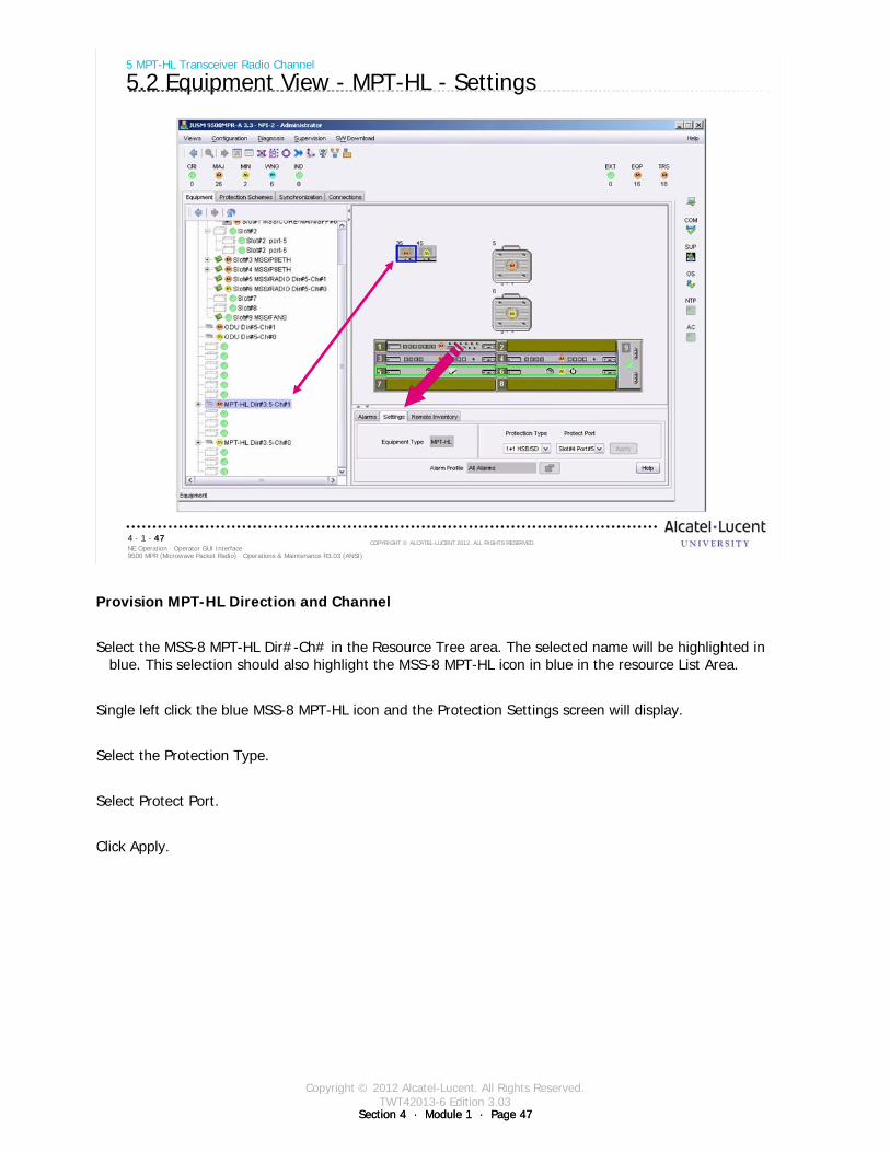
Copyright © 2012 Alcatel-Lucent. All Rights Reserved.TWT42013-6 Edition 3.03
Section 4 · Module 1 · Page 47Section 4 · Module 1 · Page 47
9500 MPR (Microwave Packet Radio) · Operations & Maintenance R3.03 (ANSI)NE Operation · Operator GUI Interface4 · 1 · 47
COPYRIGHT © ALCATEL-LUCENT 2012. ALL RIGHTS RESERVED.
5 MPT-HL Transceiver Radio Channel
5.2 Equipment View - MPT-HL - Settings
Provision MPT-HL Direction and Channel
Select the MSS-8 MPT-HL Dir#-Ch# in the Resource Tree area. The selected name will be highlighted in blue. This selection should also highlight the MSS-8 MPT-HL icon in blue in the resource List Area.
Single left click the blue MSS-8 MPT-HL icon and the Protection Settings screen will display.
Select the Protection Type.
Select Protect Port.
Click Apply.

Copyright © 2012 Alcatel-Lucent. All Rights Reserved.TWT42013-6 Edition 3.03
Section 4 · Module 1 · Page 48Section 4 · Module 1 · Page 48
9500 MPR (Microwave Packet Radio) · Operations & Maintenance R3.03 (ANSI)NE Operation · Operator GUI Interface4 · 1 · 48
COPYRIGHT © ALCATEL-LUCENT 2012. ALL RIGHTS RESERVED.
5 MPT-HL Transceiver Radio Channel
5.3 Equipment View - MPT-HL
Double-click MPT-HL
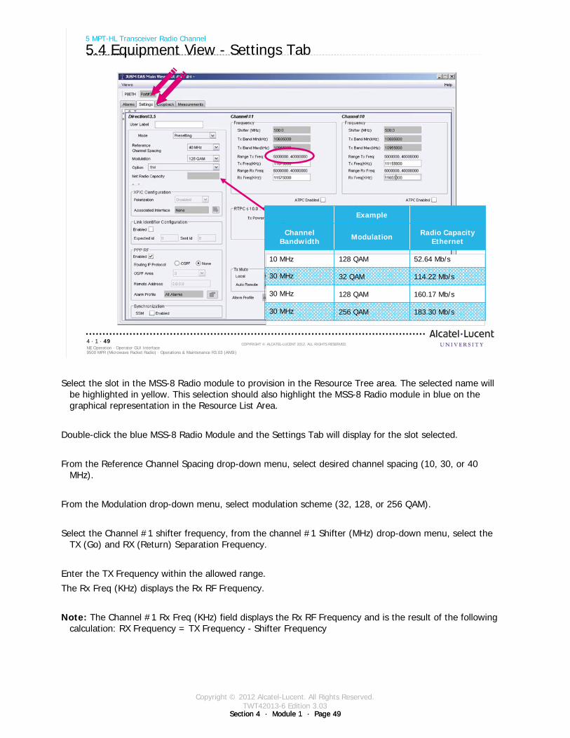
Copyright © 2012 Alcatel-Lucent. All Rights Reserved.TWT42013-6 Edition 3.03
Section 4 · Module 1 · Page 49Section 4 · Module 1 · Page 49
9500 MPR (Microwave Packet Radio) · Operations & Maintenance R3.03 (ANSI)NE Operation · Operator GUI Interface4 · 1 · 49
COPYRIGHT © ALCATEL-LUCENT 2012. ALL RIGHTS RESERVED.
5 MPT-HL Transceiver Radio Channel
5.4 Equipment View - Settings Tab
Example
Channel Bandwidth Modulation Radio Capacity
Ethernet
10 MHz 128 QAM 52.64 Mb/s
30 MHz 32 QAM 114.22 Mb/s
30 MHz 128 QAM 160.17 Mb/s
30 MHz 256 QAM 183.30 Mb/s
Select the slot in the MSS-8 Radio module to provision in the Resource Tree area. The selected name will be highlighted in yellow. This selection should also highlight the MSS-8 Radio module in blue on the graphical representation in the Resource List Area.
Double-click the blue MSS-8 Radio Module and the Settings Tab will display for the slot selected.
From the Reference Channel Spacing drop-down menu, select desired channel spacing (10, 30, or 40 MHz).
From the Modulation drop-down menu, select modulation scheme (32, 128, or 256 QAM).
Select the Channel #1 shifter frequency, from the channel #1 Shifter (MHz) drop-down menu, select the TX (Go) and RX (Return) Separation Frequency.
Enter the TX Frequency within the allowed range.
The Rx Freq (KHz) displays the Rx RF Frequency.
Note: The Channel #1 Rx Freq (KHz) field displays the Rx RF Frequency and is the result of the following calculation: RX Frequency = TX Frequency - Shifter Frequency
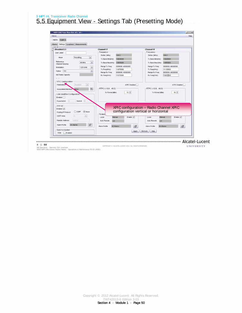
Copyright © 2012 Alcatel-Lucent. All Rights Reserved.TWT42013-6 Edition 3.03
Section 4 · Module 1 · Page 50Section 4 · Module 1 · Page 50
9500 MPR (Microwave Packet Radio) · Operations & Maintenance R3.03 (ANSI)NE Operation · Operator GUI Interface4 · 1 · 50
COPYRIGHT © ALCATEL-LUCENT 2012. ALL RIGHTS RESERVED.
XPIC configuration – Radio Channel XPIC configuration vertical or horizontal
5 MPT-HL Transceiver Radio Channel
5.5 Equipment View - Settings Tab (Presetting Mode)
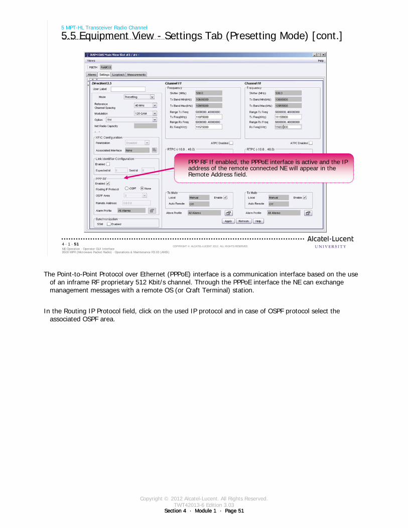
Copyright © 2012 Alcatel-Lucent. All Rights Reserved.TWT42013-6 Edition 3.03
Section 4 · Module 1 · Page 51Section 4 · Module 1 · Page 51
9500 MPR (Microwave Packet Radio) · Operations & Maintenance R3.03 (ANSI)NE Operation · Operator GUI Interface4 · 1 · 51
COPYRIGHT © ALCATEL-LUCENT 2012. ALL RIGHTS RESERVED.
5 MPT-HL Transceiver Radio Channel
5.5 Equipment View - Settings Tab (Presetting Mode) [cont.]
PPP RF If enabled, the PPPoE interface is active and the IP address of the remote connected NE will appear in the Remote Address field.
The Point-to-Point Protocol over Ethernet (PPPoE) interface is a communication interface based on the use of an inframe RF proprietary 512 Kbit/s channel. Through the PPPoE interface the NE can exchange management messages with a remote OS (or Craft Terminal) station.
In the Routing IP Protocol field, click on the used IP protocol and in case of OSPF protocol select the associated OSPF area.
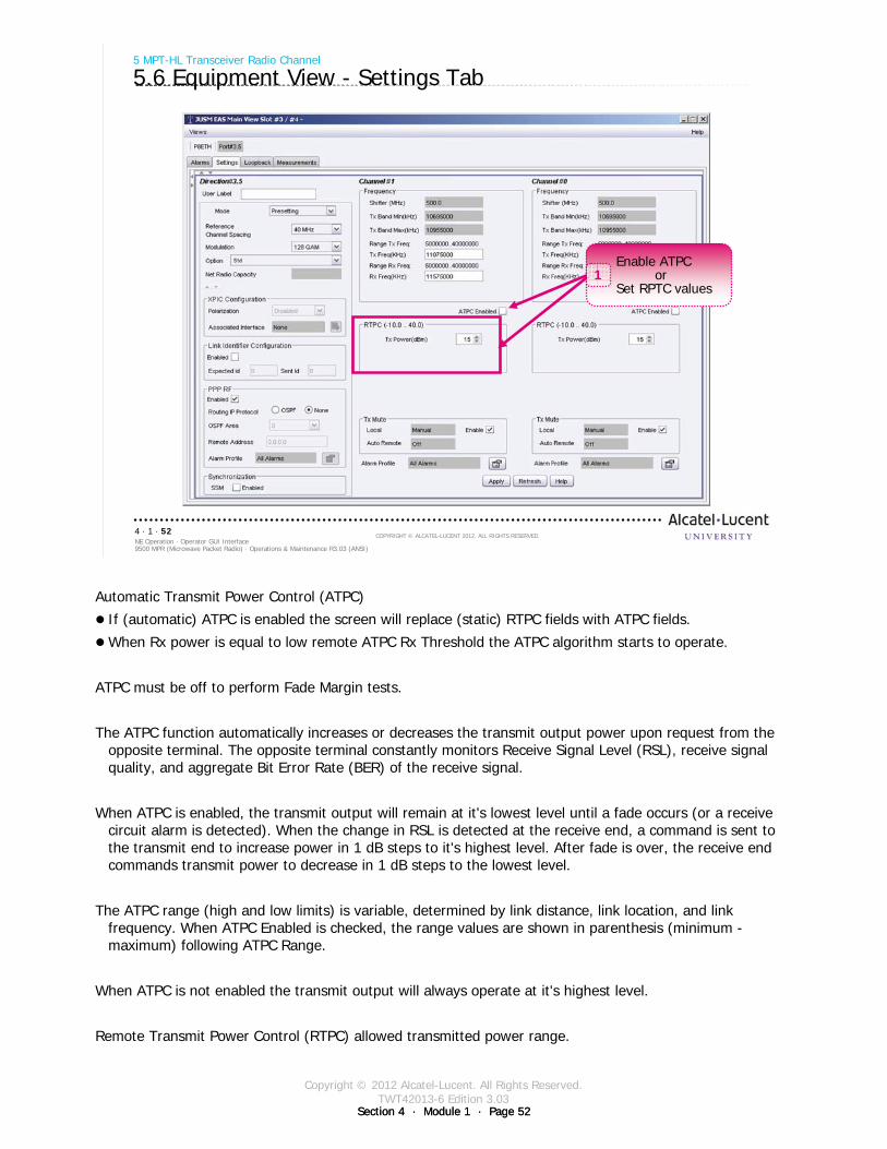
Copyright © 2012 Alcatel-Lucent. All Rights Reserved.TWT42013-6 Edition 3.03
Section 4 · Module 1 · Page 52Section 4 · Module 1 · Page 52
9500 MPR (Microwave Packet Radio) · Operations & Maintenance R3.03 (ANSI)NE Operation · Operator GUI Interface4 · 1 · 52
COPYRIGHT © ALCATEL-LUCENT 2012. ALL RIGHTS RESERVED.
Enable ATPCor
Set RPTC values1
5 MPT-HL Transceiver Radio Channel
5.6 Equipment View - Settings Tab
Automatic Transmit Power Control (ATPC)
If (automatic) ATPC is enabled the screen will replace (static) RTPC fields with ATPC fields.
When Rx power is equal to low remote ATPC Rx Threshold the ATPC algorithm starts to operate.
ATPC must be off to perform Fade Margin tests.
The ATPC function automatically increases or decreases the transmit output power upon request from the opposite terminal. The opposite terminal constantly monitors Receive Signal Level (RSL), receive signal quality, and aggregate Bit Error Rate (BER) of the receive signal.
When ATPC is enabled, the transmit output will remain at it's lowest level until a fade occurs (or a receive circuit alarm is detected). When the change in RSL is detected at the receive end, a command is sent to the transmit end to increase power in 1 dB steps to it's highest level. After fade is over, the receive end commands transmit power to decrease in 1 dB steps to the lowest level.
The ATPC range (high and low limits) is variable, determined by link distance, link location, and link frequency. When ATPC Enabled is checked, the range values are shown in parenthesis (minimum -maximum) following ATPC Range.
When ATPC is not enabled the transmit output will always operate at it's highest level.
Remote Transmit Power Control (RTPC) allowed transmitted power range.

Copyright © 2012 Alcatel-Lucent. All Rights Reserved.TWT42013-6 Edition 3.03
Section 4 · Module 1 · Page 53Section 4 · Module 1 · Page 53
9500 MPR (Microwave Packet Radio) · Operations & Maintenance R3.03 (ANSI)NE Operation · Operator GUI Interface4 · 1 · 53
COPYRIGHT © ALCATEL-LUCENT 2012. ALL RIGHTS RESERVED.
5 MPT-HL Transceiver Radio Channel
5.7 Equipment View - Settings Tab - Alarm Profile
Click alarm Profile1
Select Show details2

Copyright © 2012 Alcatel-Lucent. All Rights Reserved.TWT42013-6 Edition 3.03
Section 4 · Module 1 · Page 54Section 4 · Module 1 · Page 54
9500 MPR (Microwave Packet Radio) · Operations & Maintenance R3.03 (ANSI)NE Operation · Operator GUI Interface4 · 1 · 54
COPYRIGHT © ALCATEL-LUCENT 2012. ALL RIGHTS RESERVED.
Blank page
Switch to notes view!
This page intentionally left blank

Copyright © 2012 Alcatel-Lucent. All Rights Reserved.TWT42013-6 Edition 3.03
Section 4 · Module 1 · Page 55
9500 MPR (Microwave Packet Radio) · Operations & Maintenance R3.03 (ANSI)NE Operation · Operator GUI Interface4 · 1 · 55
COPYRIGHT © ALCATEL-LUCENT 2012. ALL RIGHTS RESERVED.
6 MOD300 Radio Channel
Refer to 9500 MPR Operation and Administration, 3EM23954AHAA, DLP-109 for more details
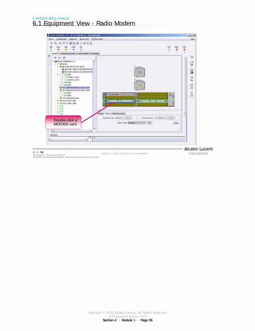
Copyright © 2012 Alcatel-Lucent. All Rights Reserved.TWT42013-6 Edition 3.03
Section 4 · Module 1 · Page 56
9500 MPR (Microwave Packet Radio) · Operations & Maintenance R3.03 (ANSI)NE Operation · Operator GUI Interface4 · 1 · 56
COPYRIGHT © ALCATEL-LUCENT 2012. ALL RIGHTS RESERVED.
6 MOD300 Radio Channel
6.1 Equipment View - Radio Modem
Double-click a MOD300 card
Section 4 · Module 1 · Page 56

Copyright © 2012 Alcatel-Lucent. All Rights Reserved.TWT42013-6 Edition 3.03
Section 4 · Module 1 · Page 57
9500 MPR (Microwave Packet Radio) · Operations & Maintenance R3.03 (ANSI)NE Operation · Operator GUI Interface4 · 1 · 57
COPYRIGHT © ALCATEL-LUCENT 2012. ALL RIGHTS RESERVED.
6 MOD300 Radio Channel
6.2 Radio Modem Settings Tab - Adaptive Modulation Mode
Select Adaptive Modulaiton1
Rx frequency automatically populated when TX frequency is set
Set Reference Channel Spacing, Modulation, and gain
2
Select Channel 1 Shifter Frequency3
Set Tx frequency4
Click Apply5
Section 4 · Module 1 · Page 57
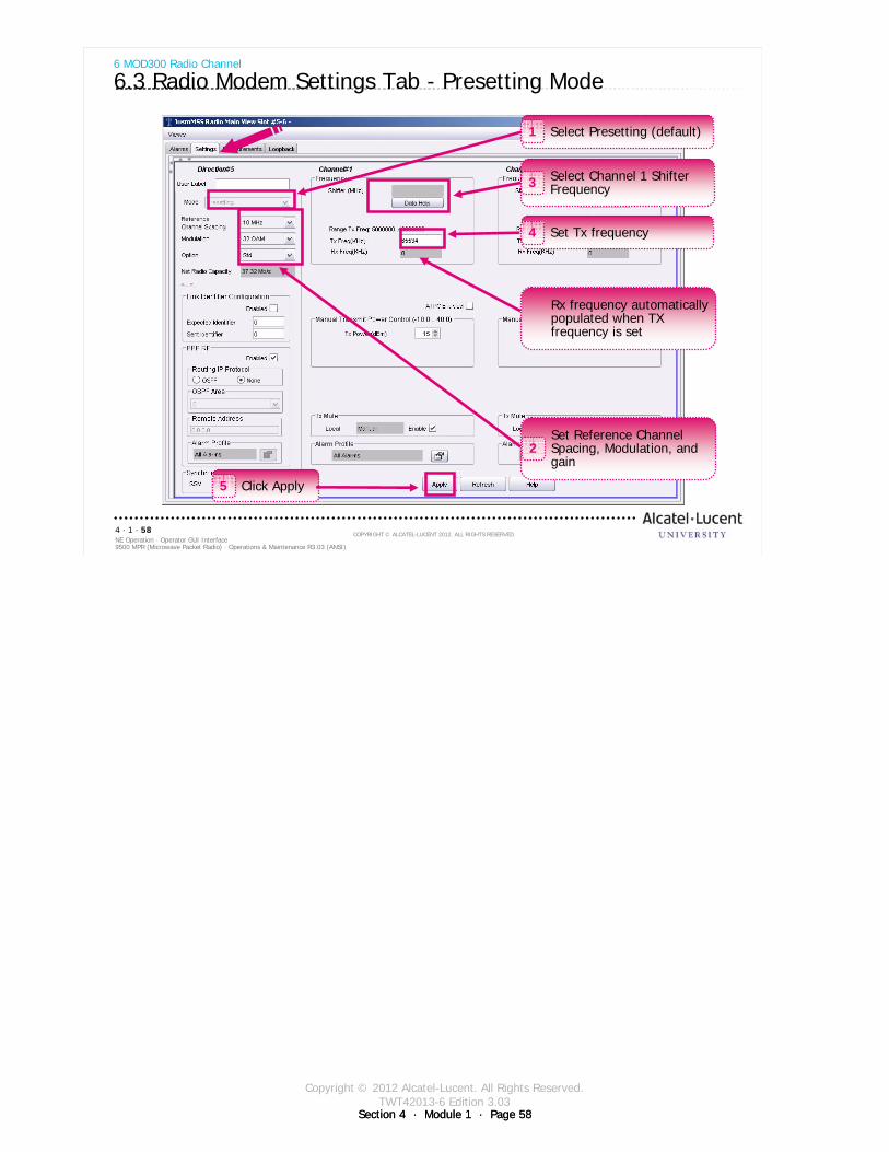
Copyright © 2012 Alcatel-Lucent. All Rights Reserved.TWT42013-6 Edition 3.03
Section 4 · Module 1 · Page 58
9500 MPR (Microwave Packet Radio) · Operations & Maintenance R3.03 (ANSI)NE Operation · Operator GUI Interface4 · 1 · 58
COPYRIGHT © ALCATEL-LUCENT 2012. ALL RIGHTS RESERVED.
6 MOD300 Radio Channel
6.3 Radio Modem Settings Tab - Presetting Mode
Select Presetting (default)1
Rx frequency automatically populated when TX frequency is set
Set Reference Channel Spacing, Modulation, and gain
2
Select Channel 1 Shifter Frequency3
Set Tx frequency4
Click Apply5
Section 4 · Module 1 · Page 58
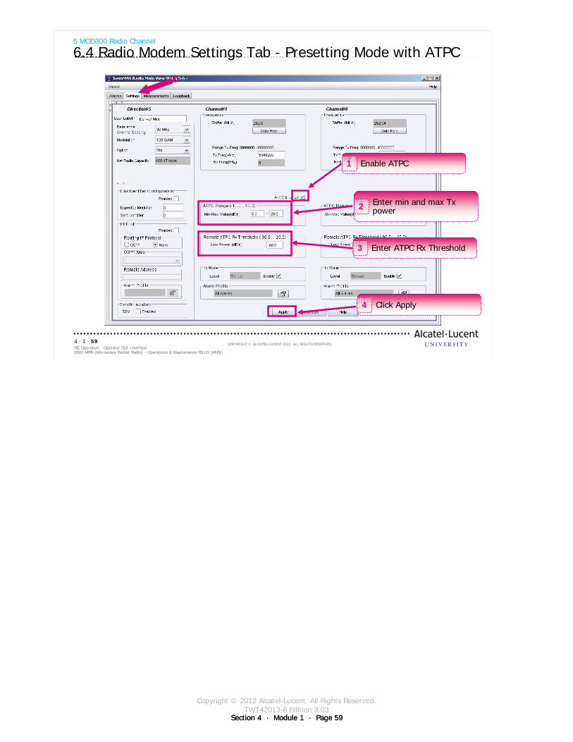
Copyright © 2012 Alcatel-Lucent. All Rights Reserved.TWT42013-6 Edition 3.03
Section 4 · Module 1 · Page 59
9500 MPR (Microwave Packet Radio) · Operations & Maintenance R3.03 (ANSI)NE Operation · Operator GUI Interface4 · 1 · 59
COPYRIGHT © ALCATEL-LUCENT 2012. ALL RIGHTS RESERVED.
6 MOD300 Radio Channel
6.4 Radio Modem Settings Tab - Presetting Mode with ATPC
Enable ATPC1
Enter min and max Tx power2
Enter ATPC Rx Threshold3
Click Apply4
Section 4 · Module 1 · Page 59
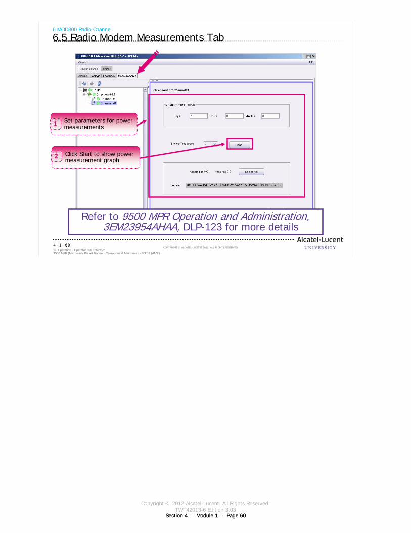
Copyright © 2012 Alcatel-Lucent. All Rights Reserved.TWT42013-6 Edition 3.03
Section 4 · Module 1 · Page 60
9500 MPR (Microwave Packet Radio) · Operations & Maintenance R3.03 (ANSI)NE Operation · Operator GUI Interface4 · 1 · 60
COPYRIGHT © ALCATEL-LUCENT 2012. ALL RIGHTS RESERVED.
6 MOD300 Radio Channel
6.5 Radio Modem Measurements Tab
Click Start to show power measurement graph
2
Set parameters for power measurements1
Refer to 9500 MPR Operation and Administration, 3EM23954AHAA, DLP-123 for more details
Section 4 · Module 1 · Page 60

Copyright © 2012 Alcatel-Lucent. All Rights Reserved.TWT42013-6 Edition 3.03
Section 4 · Module 1 · Page 61
9500 MPR (Microwave Packet Radio) · Operations & Maintenance R3.03 (ANSI)NE Operation · Operator GUI Interface4 · 1 · 61
COPYRIGHT © ALCATEL-LUCENT 2012. ALL RIGHTS RESERVED.
6 MOD300 Radio Channel
6.6 Radio Modem Power Measurements Graphic
Section 4 · Module 1 · Page 61

Copyright © 2012 Alcatel-Lucent. All Rights Reserved.TWT42013-6 Edition 3.03
Section 4 · Module 1 · Page 62Section 4 · Module 1 · Page 62
9500 MPR (Microwave Packet Radio) · Operations & Maintenance R3.03 (ANSI)NE Operation · Operator GUI Interface4 · 1 · 62
COPYRIGHT © ALCATEL-LUCENT 2012. ALL RIGHTS RESERVED.
Blank page
Switch to notes view!
This page intentionally left blank

Copyright © 2012 Alcatel-Lucent. All Rights Reserved.TWT42013-6 Edition 3.03
Section 4 · Module 1 · Page 63
9500 MPR (Microwave Packet Radio) · Operations & Maintenance R3.03 (ANSI)NE Operation · Operator GUI Interface4 · 1 · 63
COPYRIGHT © ALCATEL-LUCENT 2012. ALL RIGHTS RESERVED.
7 MPT-HC Radio Channel
Refer to 9500 MPR Operation and Administration, 3EM23954AHAA, DLP-109 for more details
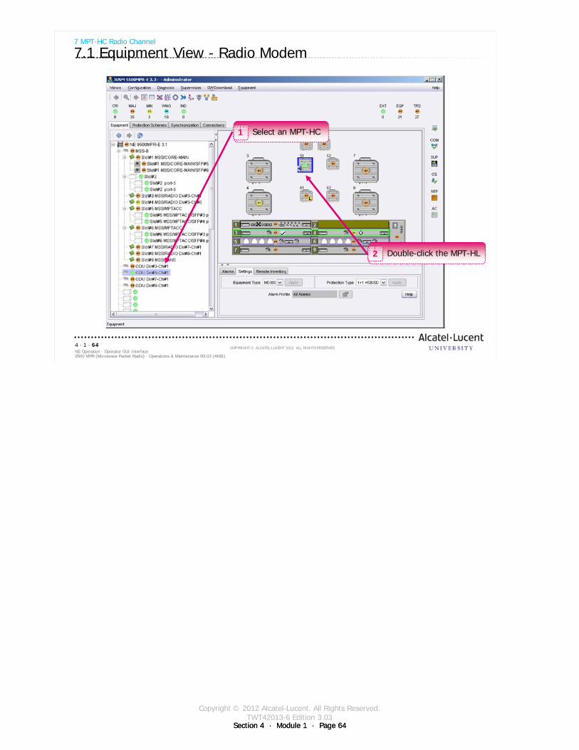
Copyright © 2012 Alcatel-Lucent. All Rights Reserved.TWT42013-6 Edition 3.03
Section 4 · Module 1 · Page 64
9500 MPR (Microwave Packet Radio) · Operations & Maintenance R3.03 (ANSI)NE Operation · Operator GUI Interface4 · 1 · 64
COPYRIGHT © ALCATEL-LUCENT 2012. ALL RIGHTS RESERVED.
7 MPT-HC Radio Channel
7.1 Equipment View - Radio Modem
Double-click the MPT-HL2
Select an MPT-HC1
Section 4 · Module 1 · Page 64
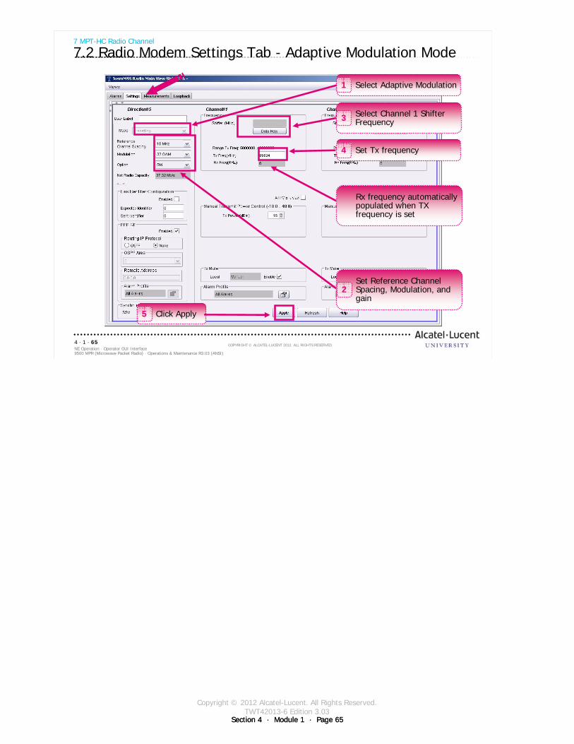
Copyright © 2012 Alcatel-Lucent. All Rights Reserved.TWT42013-6 Edition 3.03
Section 4 · Module 1 · Page 65
9500 MPR (Microwave Packet Radio) · Operations & Maintenance R3.03 (ANSI)NE Operation · Operator GUI Interface4 · 1 · 65
COPYRIGHT © ALCATEL-LUCENT 2012. ALL RIGHTS RESERVED.
7 MPT-HC Radio Channel
7.2 Radio Modem Settings Tab - Adaptive Modulation Mode
Select Adaptive Modulation1
Rx frequency automatically populated when TX frequency is set
Set Reference Channel Spacing, Modulation, and gain
2
Select Channel 1 Shifter Frequency3
Set Tx frequency4
Click Apply5
Section 4 · Module 1 · Page 65
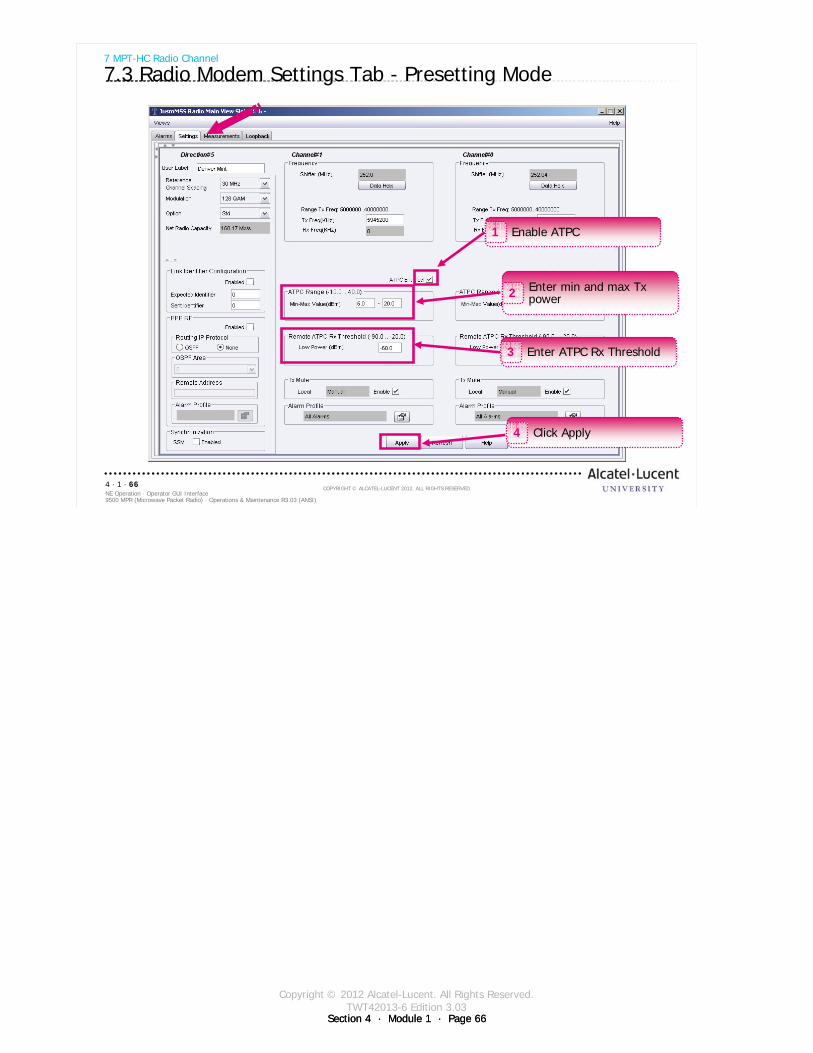
Copyright © 2012 Alcatel-Lucent. All Rights Reserved.TWT42013-6 Edition 3.03
Section 4 · Module 1 · Page 66
9500 MPR (Microwave Packet Radio) · Operations & Maintenance R3.03 (ANSI)NE Operation · Operator GUI Interface4 · 1 · 66
COPYRIGHT © ALCATEL-LUCENT 2012. ALL RIGHTS RESERVED.
7 MPT-HC Radio Channel
7.3 Radio Modem Settings Tab - Presetting Mode
Enable ATPC1
Enter min and max Tx power2
Enter ATPC Rx Threshold3
Click Apply4
Section 4 · Module 1 · Page 66
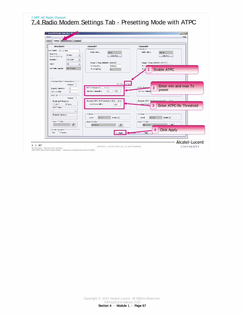
Copyright © 2012 Alcatel-Lucent. All Rights Reserved.TWT42013-6 Edition 3.03
Section 4 · Module 1 · Page 67
9500 MPR (Microwave Packet Radio) · Operations & Maintenance R3.03 (ANSI)NE Operation · Operator GUI Interface4 · 1 · 67
COPYRIGHT © ALCATEL-LUCENT 2012. ALL RIGHTS RESERVED.
7 MPT-HC Radio Channel
7.4 Radio Modem Settings Tab - Presetting Mode with ATPC
Enable ATPC1
Enter min and max Tx power2
Enter ATPC Rx Threshold3
Click Apply4
Section 4 · Module 1 · Page 67

Copyright © 2012 Alcatel-Lucent. All Rights Reserved.TWT42013-6 Edition 3.03
Section 4 · Module 1 · Page 68
9500 MPR (Microwave Packet Radio) · Operations & Maintenance R3.03 (ANSI)NE Operation · Operator GUI Interface4 · 1 · 68
COPYRIGHT © ALCATEL-LUCENT 2012. ALL RIGHTS RESERVED.
7 MPT-HC Radio Channel
7.5 Radio Modem Measurements Tab
Click Start to show power measurement graph
2
Set parameters for power measurements1
Refer to 9500 MPR Operation and Administration, 3EM23954AHAA, DLP-123 for more details
Section 4 · Module 1 · Page 68
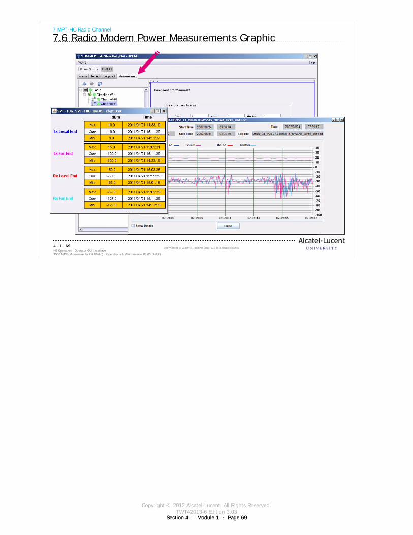
Copyright © 2012 Alcatel-Lucent. All Rights Reserved.TWT42013-6 Edition 3.03
Section 4 · Module 1 · Page 69
9500 MPR (Microwave Packet Radio) · Operations & Maintenance R3.03 (ANSI)NE Operation · Operator GUI Interface4 · 1 · 69
COPYRIGHT © ALCATEL-LUCENT 2012. ALL RIGHTS RESERVED.
7 MPT-HC Radio Channel
7.6 Radio Modem Power Measurements Graphic
Section 4 · Module 1 · Page 69

Copyright © 2012 Alcatel-Lucent. All Rights Reserved.TWT42013-6 Edition 3.03
Section 4 · Module 1 · Page 70Section 4 · Module 1 · Page 70
9500 MPR (Microwave Packet Radio) · Operations & Maintenance R3.03 (ANSI)NE Operation · Operator GUI Interface4 · 1 · 70
COPYRIGHT © ALCATEL-LUCENT 2012. ALL RIGHTS RESERVED.
Blank page
Switch to notes view!
This page intentionally left blank

Copyright © 2012 Alcatel-Lucent. All Rights Reserved.TWT42013-6 Edition 3.03
Section 4 · Module 1 · Page 71
9500 MPR (Microwave Packet Radio) · Operations & Maintenance R3.03 (ANSI)NE Operation · Operator GUI Interface4 · 1 · 71
COPYRIGHT © ALCATEL-LUCENT 2012. ALL RIGHTS RESERVED.
8 Configuration Menu
Refer to 9500 MPR Operation and Administration, 3EM23954AHAA, DLP-118 for more details
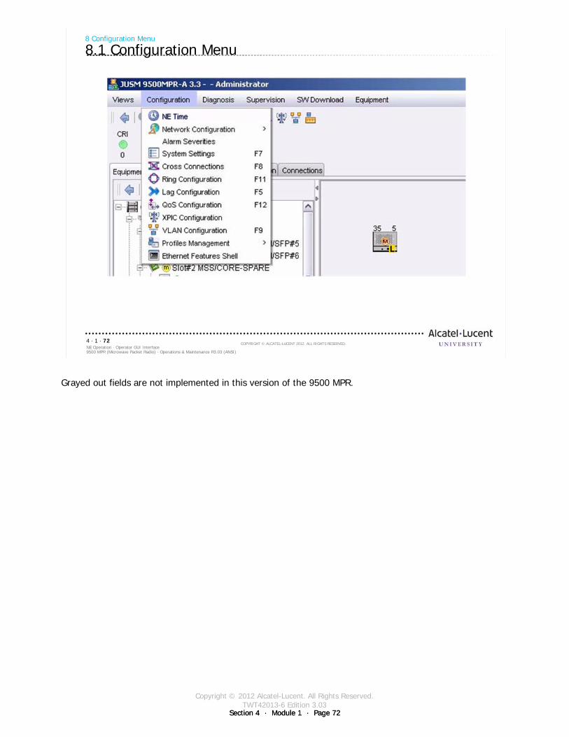
Copyright © 2012 Alcatel-Lucent. All Rights Reserved.TWT42013-6 Edition 3.03
Section 4 · Module 1 · Page 72Section 4 · Module 1 · Page 72
9500 MPR (Microwave Packet Radio) · Operations & Maintenance R3.03 (ANSI)NE Operation · Operator GUI Interface4 · 1 · 72
COPYRIGHT © ALCATEL-LUCENT 2012. ALL RIGHTS RESERVED.
8 Configuration Menu
8.1 Configuration Menu
Grayed out fields are not implemented in this version of the 9500 MPR.
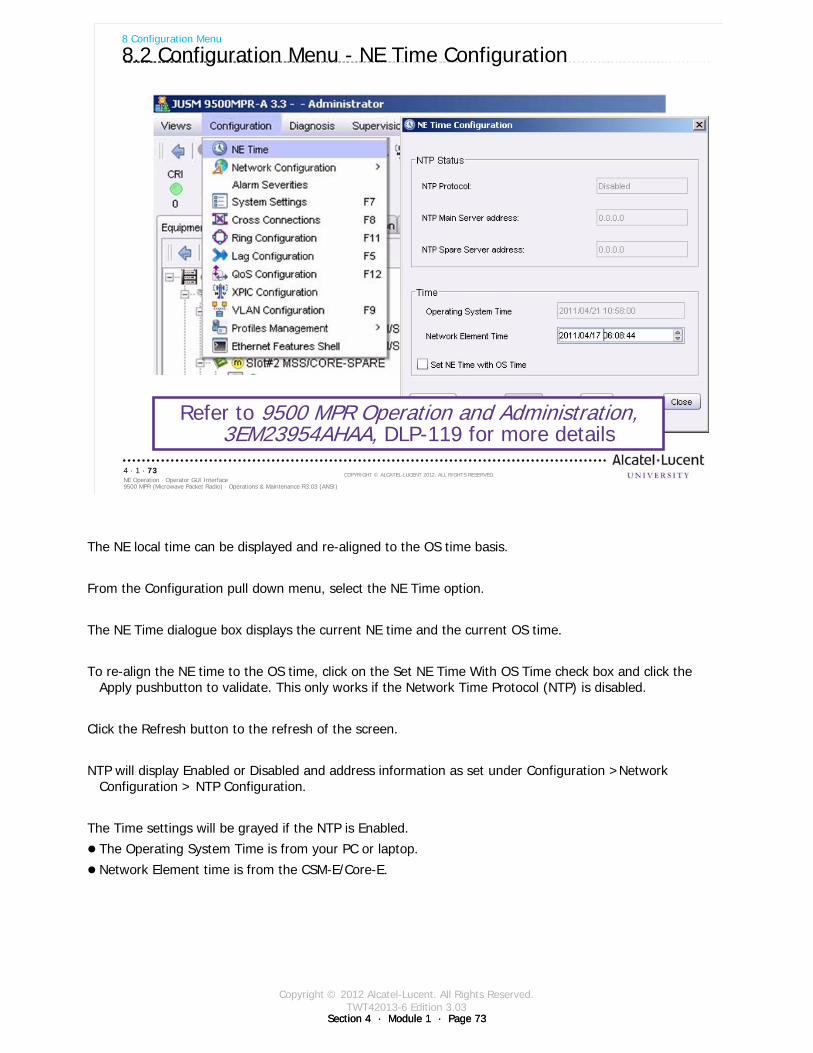
Copyright © 2012 Alcatel-Lucent. All Rights Reserved.TWT42013-6 Edition 3.03
Section 4 · Module 1 · Page 73Section 4 · Module 1 · Page 73
9500 MPR (Microwave Packet Radio) · Operations & Maintenance R3.03 (ANSI)NE Operation · Operator GUI Interface4 · 1 · 73
COPYRIGHT © ALCATEL-LUCENT 2012. ALL RIGHTS RESERVED.
8 Configuration Menu
8.2 Configuration Menu - NE Time Configuration
Refer to 9500 MPR Operation and Administration, 3EM23954AHAA, DLP-119 for more details
The NE local time can be displayed and re-aligned to the OS time basis.
From the Configuration pull down menu, select the NE Time option.
The NE Time dialogue box displays the current NE time and the current OS time.
To re-align the NE time to the OS time, click on the Set NE Time With OS Time check box and click the Apply pushbutton to validate. This only works if the Network Time Protocol (NTP) is disabled.
Click the Refresh button to the refresh of the screen.
NTP will display Enabled or Disabled and address information as set under Configuration >Network Configuration > NTP Configuration.
The Time settings will be grayed if the NTP is Enabled.
The Operating System Time is from your PC or laptop.
Network Element time is from the CSM-E/Core-E.
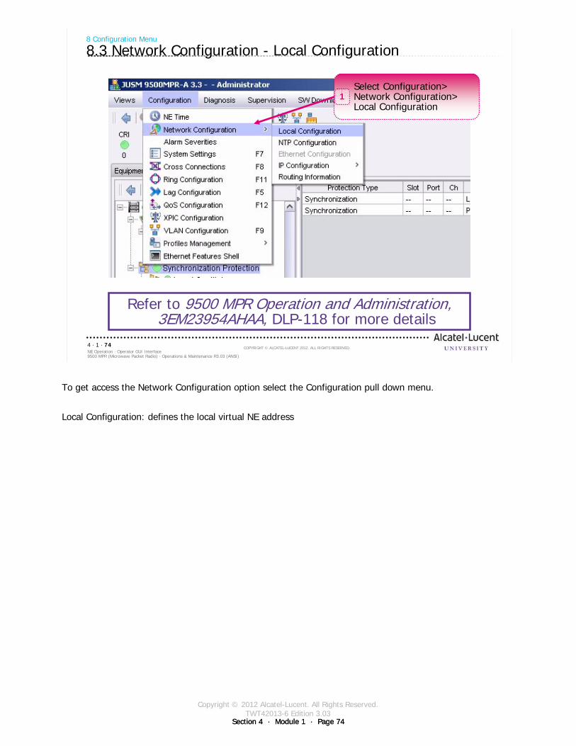
Copyright © 2012 Alcatel-Lucent. All Rights Reserved.TWT42013-6 Edition 3.03
Section 4 · Module 1 · Page 74Section 4 · Module 1 · Page 74
9500 MPR (Microwave Packet Radio) · Operations & Maintenance R3.03 (ANSI)NE Operation · Operator GUI Interface4 · 1 · 74
COPYRIGHT © ALCATEL-LUCENT 2012. ALL RIGHTS RESERVED.
8 Configuration Menu
8.3 Network Configuration - Local Configuration
Refer to 9500 MPR Operation and Administration, 3EM23954AHAA, DLP-118 for more details
Select Configuration>Network Configuration>Local Configuration
1
To get access the Network Configuration option select the Configuration pull down menu.
Local Configuration: defines the local virtual NE address
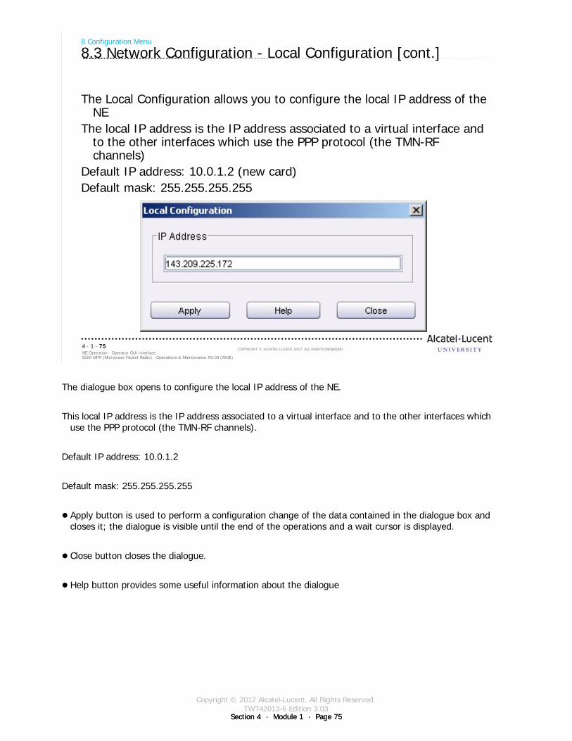
Copyright © 2012 Alcatel-Lucent. All Rights Reserved.TWT42013-6 Edition 3.03
Section 4 · Module 1 · Page 75Section 4 · Module 1 · Page 75
9500 MPR (Microwave Packet Radio) · Operations & Maintenance R3.03 (ANSI)NE Operation · Operator GUI Interface4 · 1 · 75
COPYRIGHT © ALCATEL-LUCENT 2012. ALL RIGHTS RESERVED.
The Local Configuration allows you to configure the local IP address of the NE
The local IP address is the IP address associated to a virtual interface and to the other interfaces which use the PPP protocol (the TMN-RF channels)
Default IP address: 10.0.1.2 (new card)Default mask: 255.255.255.255
8 Configuration Menu
8.3 Network Configuration - Local Configuration [cont.]
The dialogue box opens to configure the local IP address of the NE.
This local IP address is the IP address associated to a virtual interface and to the other interfaces which use the PPP protocol (the TMN-RF channels).
Default IP address: 10.0.1.2
Default mask: 255.255.255.255
Apply button is used to perform a configuration change of the data contained in the dialogue box and closes it; the dialogue is visible until the end of the operations and a wait cursor is displayed.
Close button closes the dialogue.
Help button provides some useful information about the dialogue
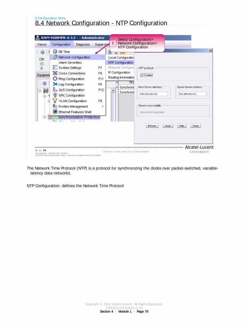
Copyright © 2012 Alcatel-Lucent. All Rights Reserved.TWT42013-6 Edition 3.03
Section 4 · Module 1 · Page 76Section 4 · Module 1 · Page 76
9500 MPR (Microwave Packet Radio) · Operations & Maintenance R3.03 (ANSI)NE Operation · Operator GUI Interface4 · 1 · 76
COPYRIGHT © ALCATEL-LUCENT 2012. ALL RIGHTS RESERVED.
8 Configuration Menu
8.4 Network Configuration - NTP Configuration
Select Configuration>Network Configuration>NTP Configuration
1
The Network Time Protocol (NTP) is a protocol for synchronizing the clocks over packet-switched, variable-latency data networks.
NTP Configuration: defines the Network Time Protocol
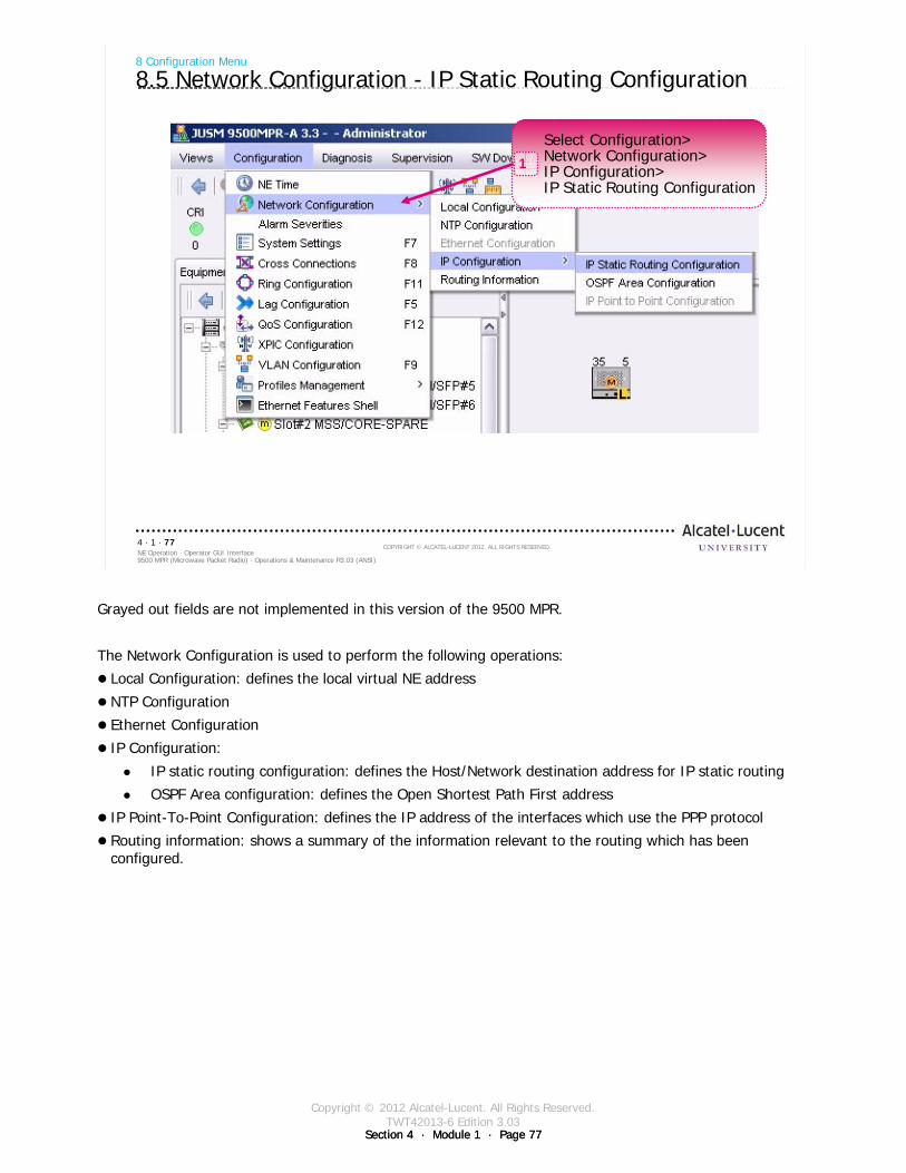
Copyright © 2012 Alcatel-Lucent. All Rights Reserved.TWT42013-6 Edition 3.03
Section 4 · Module 1 · Page 77Section 4 · Module 1 · Page 77
9500 MPR (Microwave Packet Radio) · Operations & Maintenance R3.03 (ANSI)NE Operation · Operator GUI Interface4 · 1 · 77
COPYRIGHT © ALCATEL-LUCENT 2012. ALL RIGHTS RESERVED.
8 Configuration Menu
8.5 Network Configuration - IP Static Routing Configuration
Select Configuration>Network Configuration>IP Configuration>IP Static Routing Configuration
1
Grayed out fields are not implemented in this version of the 9500 MPR.
The Network Configuration is used to perform the following operations:
Local Configuration: defines the local virtual NE address
NTP Configuration
Ethernet Configuration
IP Configuration:
IP static routing configuration: defines the Host/Network destination address for IP static routing
OSPF Area configuration: defines the Open Shortest Path First address
IP Point-To-Point Configuration: defines the IP address of the interfaces which use the PPP protocol
Routing information: shows a summary of the information relevant to the routing which has been configured.
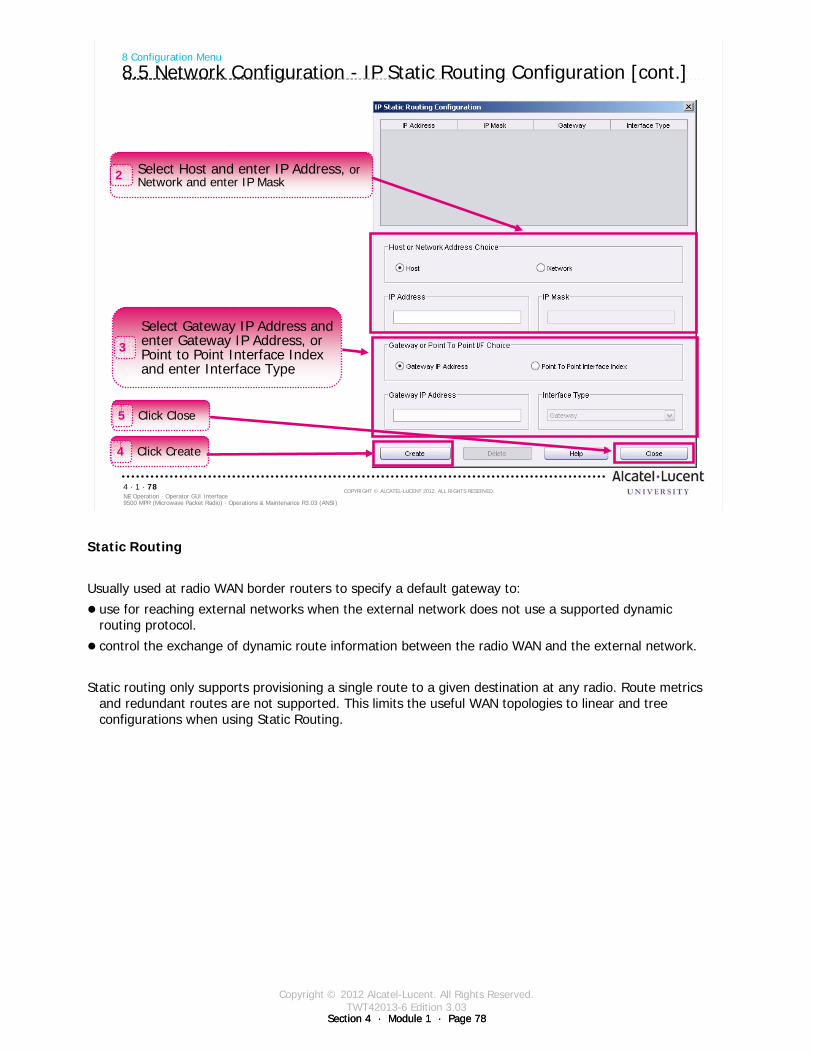
Copyright © 2012 Alcatel-Lucent. All Rights Reserved.TWT42013-6 Edition 3.03
Section 4 · Module 1 · Page 78Section 4 · Module 1 · Page 78
9500 MPR (Microwave Packet Radio) · Operations & Maintenance R3.03 (ANSI)NE Operation · Operator GUI Interface4 · 1 · 78
COPYRIGHT © ALCATEL-LUCENT 2012. ALL RIGHTS RESERVED.
8 Configuration Menu
8.5 Network Configuration - IP Static Routing Configuration [cont.]
Select Host and enter IP Address, orNetwork and enter IP Mask2
Select Gateway IP Address andenter Gateway IP Address, orPoint to Point Interface Indexand enter Interface Type
3
Click Create4
Click Close5
Static Routing
Usually used at radio WAN border routers to specify a default gateway to:
use for reaching external networks when the external network does not use a supported dynamic routing protocol.
control the exchange of dynamic route information between the radio WAN and the external network.
Static routing only supports provisioning a single route to a given destination at any radio. Route metrics and redundant routes are not supported. This limits the useful WAN topologies to linear and tree configurations when using Static Routing.
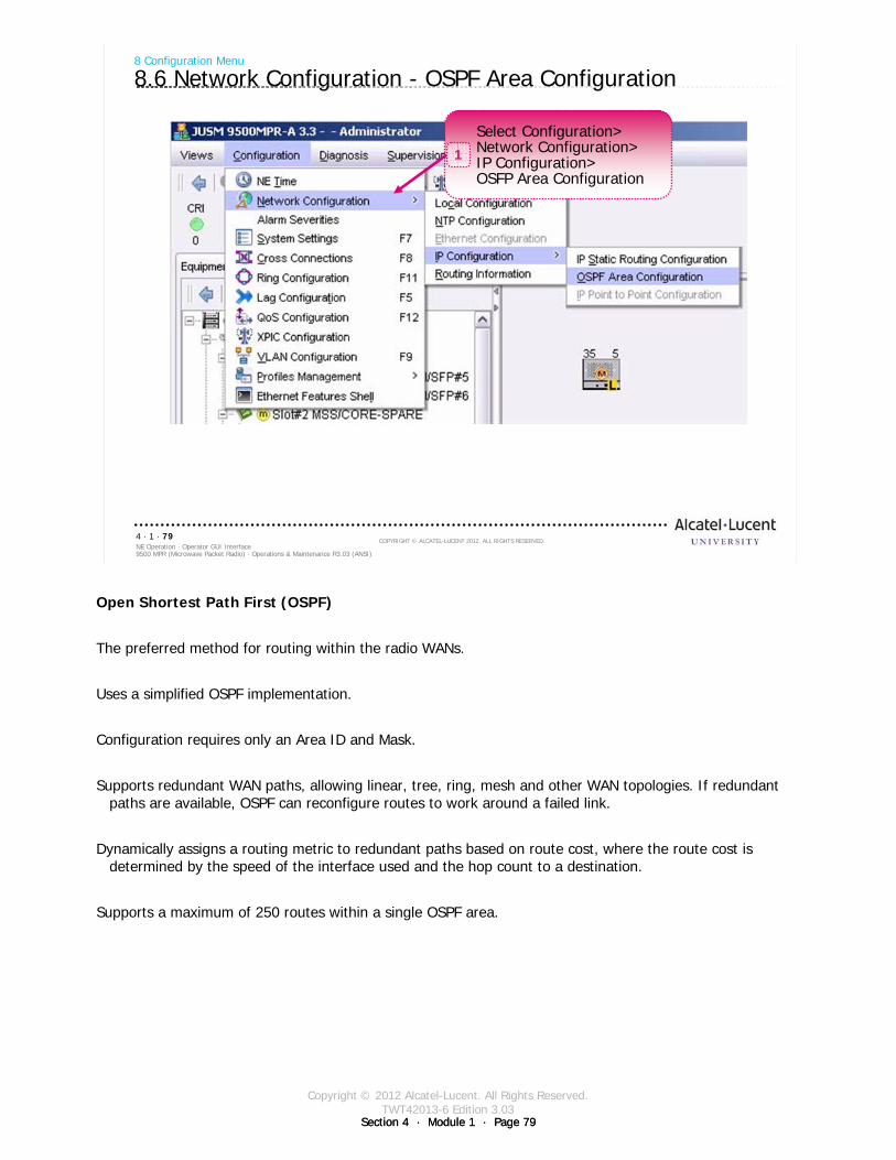
Copyright © 2012 Alcatel-Lucent. All Rights Reserved.TWT42013-6 Edition 3.03
Section 4 · Module 1 · Page 79Section 4 · Module 1 · Page 79
9500 MPR (Microwave Packet Radio) · Operations & Maintenance R3.03 (ANSI)NE Operation · Operator GUI Interface4 · 1 · 79
COPYRIGHT © ALCATEL-LUCENT 2012. ALL RIGHTS RESERVED.
8 Configuration Menu
8.6 Network Configuration - OSPF Area Configuration
Select Configuration>Network Configuration>IP Configuration>OSFP Area Configuration
1
Open Shortest Path First (OSPF)
The preferred method for routing within the radio WANs.
Uses a simplified OSPF implementation.
Configuration requires only an Area ID and Mask.
Supports redundant WAN paths, allowing linear, tree, ring, mesh and other WAN topologies. If redundant paths are available, OSPF can reconfigure routes to work around a failed link.
Dynamically assigns a routing metric to redundant paths based on route cost, where the route cost is determined by the speed of the interface used and the hop count to a destination.
Supports a maximum of 250 routes within a single OSPF area.
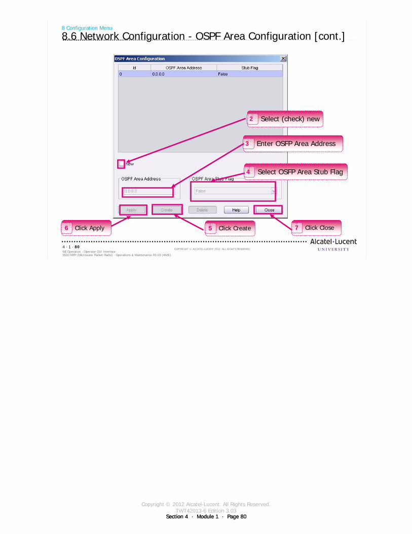
Copyright © 2012 Alcatel-Lucent. All Rights Reserved.TWT42013-6 Edition 3.03
Section 4 · Module 1 · Page 80Section 4 · Module 1 · Page 80
9500 MPR (Microwave Packet Radio) · Operations & Maintenance R3.03 (ANSI)NE Operation · Operator GUI Interface4 · 1 · 80
COPYRIGHT © ALCATEL-LUCENT 2012. ALL RIGHTS RESERVED.
8 Configuration Menu
8.6 Network Configuration - OSPF Area Configuration [cont.]
Click Create5 Click Close7Click Apply6
Select (check) new2
Enter OSFP Area Address3
Select OSFP Area Stub Flag4
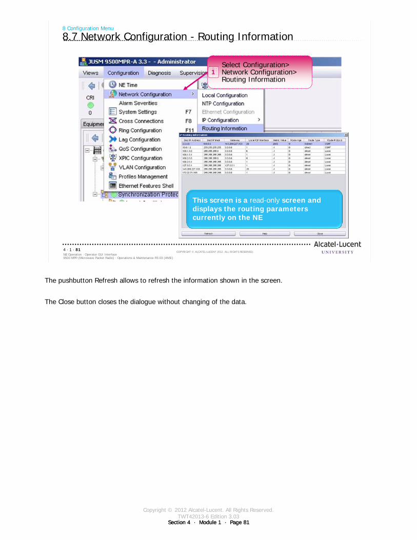
Copyright © 2012 Alcatel-Lucent. All Rights Reserved.TWT42013-6 Edition 3.03
Section 4 · Module 1 · Page 81Section 4 · Module 1 · Page 81
9500 MPR (Microwave Packet Radio) · Operations & Maintenance R3.03 (ANSI)NE Operation · Operator GUI Interface4 · 1 · 81
COPYRIGHT © ALCATEL-LUCENT 2012. ALL RIGHTS RESERVED.
8 Configuration Menu
8.7 Network Configuration - Routing Information
Select Configuration>Network Configuration>Routing Information
1
This screen is a read-only screen and displays the routing parameters currently on the NE
The pushbutton Refresh allows to refresh the information shown in the screen.
The Close button closes the dialogue without changing of the data.
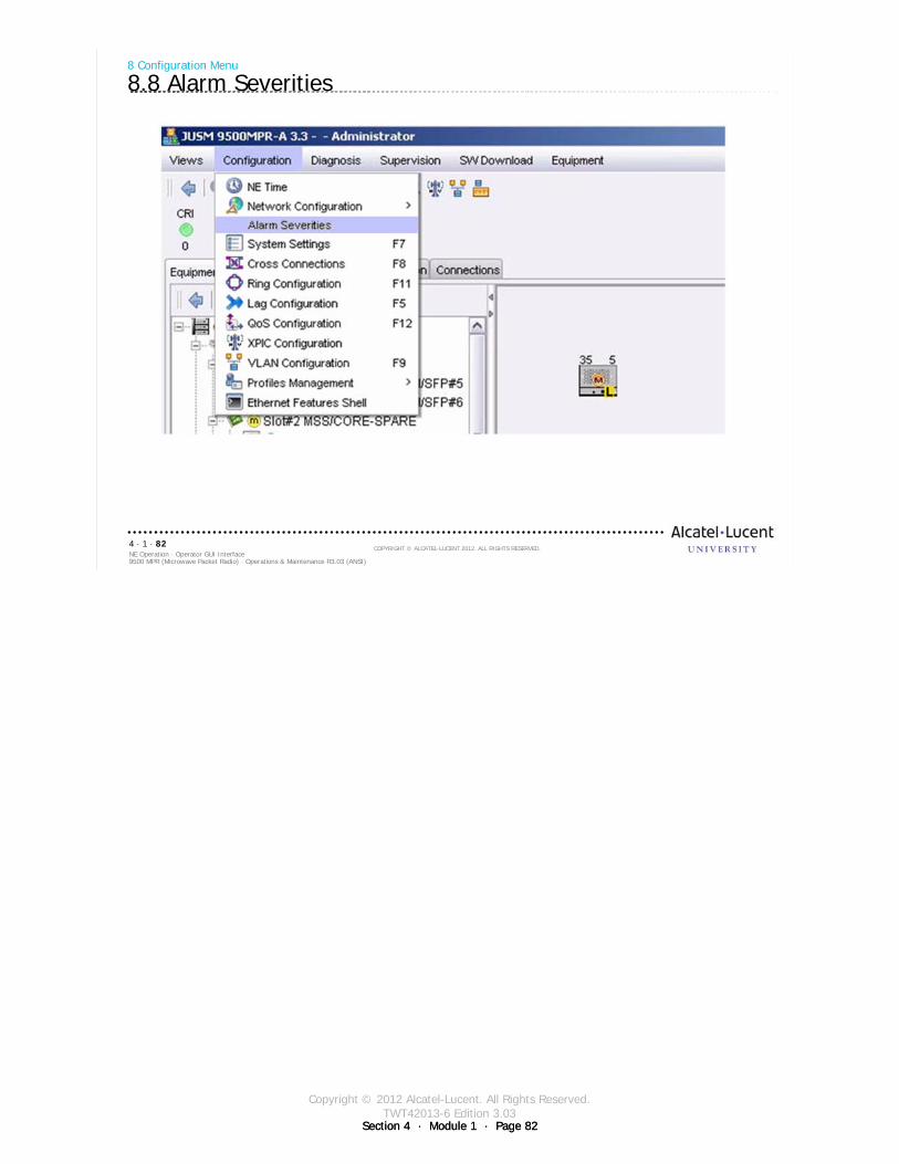
Copyright © 2012 Alcatel-Lucent. All Rights Reserved.TWT42013-6 Edition 3.03
Section 4 · Module 1 · Page 82Section 4 · Module 1 · Page 82
9500 MPR (Microwave Packet Radio) · Operations & Maintenance R3.03 (ANSI)NE Operation · Operator GUI Interface4 · 1 · 82
COPYRIGHT © ALCATEL-LUCENT 2012. ALL RIGHTS RESERVED.
8 Configuration Menu
8.8 Alarm Severities
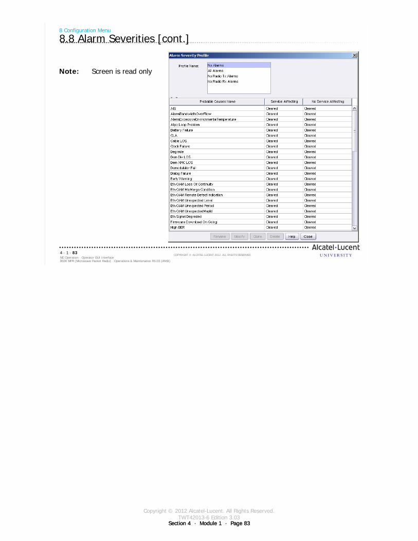
Copyright © 2012 Alcatel-Lucent. All Rights Reserved.TWT42013-6 Edition 3.03
Section 4 · Module 1 · Page 83Section 4 · Module 1 · Page 83
9500 MPR (Microwave Packet Radio) · Operations & Maintenance R3.03 (ANSI)NE Operation · Operator GUI Interface4 · 1 · 83
COPYRIGHT © ALCATEL-LUCENT 2012. ALL RIGHTS RESERVED.
8 Configuration Menu
8.8 Alarm Severities [cont.]
Note: Screen is read only

Copyright © 2012 Alcatel-Lucent. All Rights Reserved.TWT42013-6 Edition 3.03
Section 4 · Module 1 · Page 84Section 4 · Module 1 · Page 84
9500 MPR (Microwave Packet Radio) · Operations & Maintenance R3.03 (ANSI)NE Operation · Operator GUI Interface4 · 1 · 84
COPYRIGHT © ALCATEL-LUCENT 2012. ALL RIGHTS RESERVED.
Refer to 9500 MPR Operation and Administration, 3EM23954AHAA, DLP-117 for more details
8 Configuration Menu
8.9 Configuration Menu - System Settings
Select Configuration>System Settings1
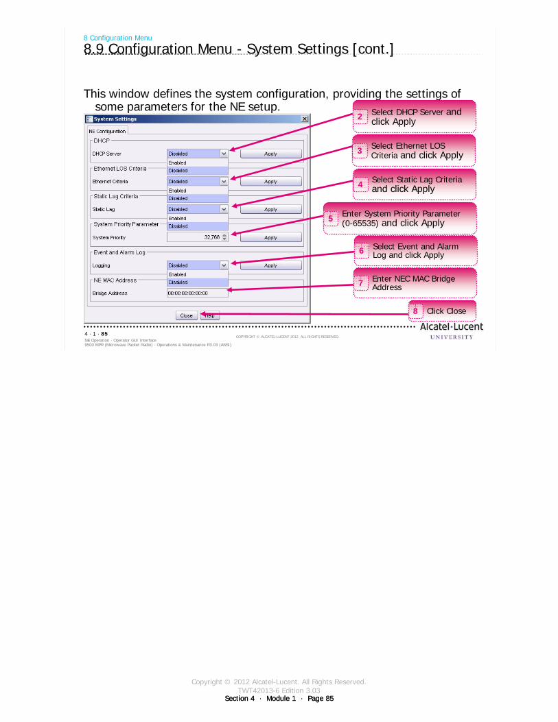
Copyright © 2012 Alcatel-Lucent. All Rights Reserved.TWT42013-6 Edition 3.03
Section 4 · Module 1 · Page 85Section 4 · Module 1 · Page 85
9500 MPR (Microwave Packet Radio) · Operations & Maintenance R3.03 (ANSI)NE Operation · Operator GUI Interface4 · 1 · 85
COPYRIGHT © ALCATEL-LUCENT 2012. ALL RIGHTS RESERVED.
This window defines the system configuration, providing the settings of some parameters for the NE setup.
8 Configuration Menu
8.9 Configuration Menu - System Settings [cont.]
Select DHCP Server and click Apply2
Select Ethernet LOS Criteria and click Apply3
Select Static Lag Criteria and click Apply4
Enter System Priority Parameter (0-65535) and click Apply5
Select Event and Alarm Log and click Apply6
Enter NEC MAC Bridge Address7
Click Close8
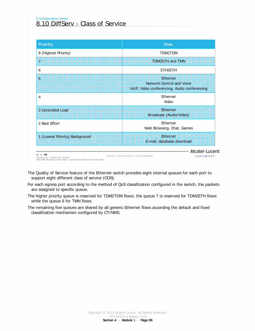
Copyright © 2012 Alcatel-Lucent. All Rights Reserved.TWT42013-6 Edition 3.03
Section 4 · Module 1 · Page 86Section 4 · Module 1 · Page 86
9500 MPR (Microwave Packet Radio) · Operations & Maintenance R3.03 (ANSI)NE Operation · Operator GUI Interface4 · 1 · 86
COPYRIGHT © ALCATEL-LUCENT 2012. ALL RIGHTS RESERVED.
8 Configuration Menu
8.10 DiffServ - Class of Service
Priority Flow
8 (Highest Priority) TDM2TDM
7 TDM2ETH and TMN
6 ETH2ETH
5 EthernetNetwork Control and Voice
VoIP, Video conferencing, Audio conferencing
4 EthernetVideo
3 Controlled Load EthernetBroadcast (Audio/Video)
2 Best Effort EthernetWeb Browsing, Chat, Games
1 (Lowest Priority) Background EthernetE-mail, database download
The Quality of Service feature of the Ethernet switch provides eight internal queues for each port to support eight different class of service (COS).
For each egress port according to the method of QoS classification configured in the switch, the packets are assigned to specific queue.
The higher priority queue is reserved for TDM2TDM flows; the queue 7 is reserved for TDM2ETH flows while the queue 6 for TMN flows.
The remaining five queues are shared by all generic Ethernet flows according the default and fixed classification mechanism configured by CT/NMS.
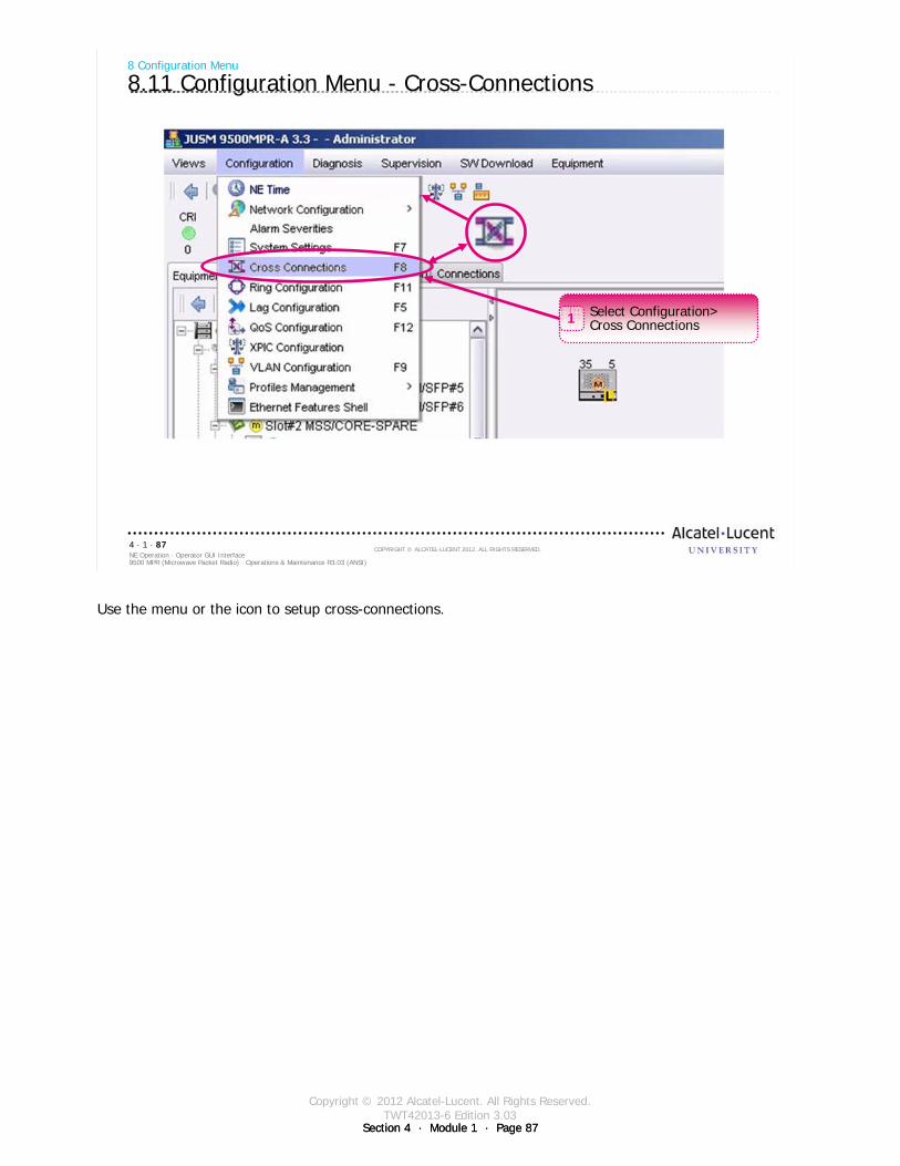
Copyright © 2012 Alcatel-Lucent. All Rights Reserved.TWT42013-6 Edition 3.03
Section 4 · Module 1 · Page 87Section 4 · Module 1 · Page 87
9500 MPR (Microwave Packet Radio) · Operations & Maintenance R3.03 (ANSI)NE Operation · Operator GUI Interface4 · 1 · 87
COPYRIGHT © ALCATEL-LUCENT 2012. ALL RIGHTS RESERVED.
8 Configuration Menu
8.11 Configuration Menu - Cross-Connections
Select Configuration>Cross Connections1
Use the menu or the icon to setup cross-connections.
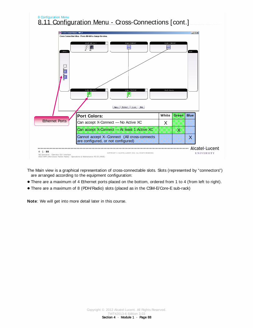
Copyright © 2012 Alcatel-Lucent. All Rights Reserved.TWT42013-6 Edition 3.03
Section 4 · Module 1 · Page 88Section 4 · Module 1 · Page 88
9500 MPR (Microwave Packet Radio) · Operations & Maintenance R3.03 (ANSI)NE Operation · Operator GUI Interface4 · 1 · 88
COPYRIGHT © ALCATEL-LUCENT 2012. ALL RIGHTS RESERVED.
8 Configuration Menu
8.11 Configuration Menu - Cross-Connections [cont.]
Port Colors: White Green Blue
Can accept X-Connect — No Active XC XCan accept X-Connect — At least 1 Active XC XCannot accept X--Connect (All cross-connects are configured, or not configured)
X
Ethernet Ports
The Main view is a graphical representation of cross-connectable slots. Slots (represented by “connectors”) are arranged according to the equipment configuration:
There are a maximum of 4 Ethernet ports placed on the bottom, ordered from 1 to 4 (from left to right).
There are a maximum of 8 (PDH/Radio) slots (placed as in the CSM-E/Core-E sub-rack)
Note: We will get into more detail later in this course.
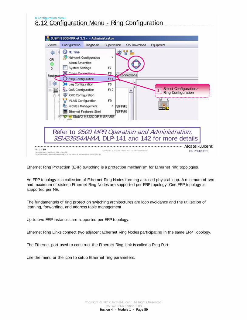
Copyright © 2012 Alcatel-Lucent. All Rights Reserved.TWT42013-6 Edition 3.03
Section 4 · Module 1 · Page 89Section 4 · Module 1 · Page 89
9500 MPR (Microwave Packet Radio) · Operations & Maintenance R3.03 (ANSI)NE Operation · Operator GUI Interface4 · 1 · 89
COPYRIGHT © ALCATEL-LUCENT 2012. ALL RIGHTS RESERVED.
8 Configuration Menu
8.12 Configuration Menu - Ring Configuration
Refer to 9500 MPR Operation and Administration, 3EM23954AHAA, DLP-141 and 142 for more details
Select Configuration>Ring Configuration1
Ethernet Ring Protection (ERP) switching is a protection mechanism for Ethernet ring topologies.
An ERP topology is a collection of Ethernet Ring Nodes forming a closed physical loop. A minimum of two and maximum of sixteen Ethernet Ring Nodes are supported per ERP topology. One ERP topology is supported per NE.
The fundamentals of ring protection switching architectures are loop avoidance and the utilization of learning, forwarding, and address table management.
Up to two ERP instances are supported per ERP topology.
Ethernet Ring Links connect two adjacent Ethernet Ring Nodes participating in the same ERP Topology.
The Ethernet port used to construct the Ethernet Ring Link is called a Ring Port.
Use the menu or the icon to setup Ethernet ring parameters.
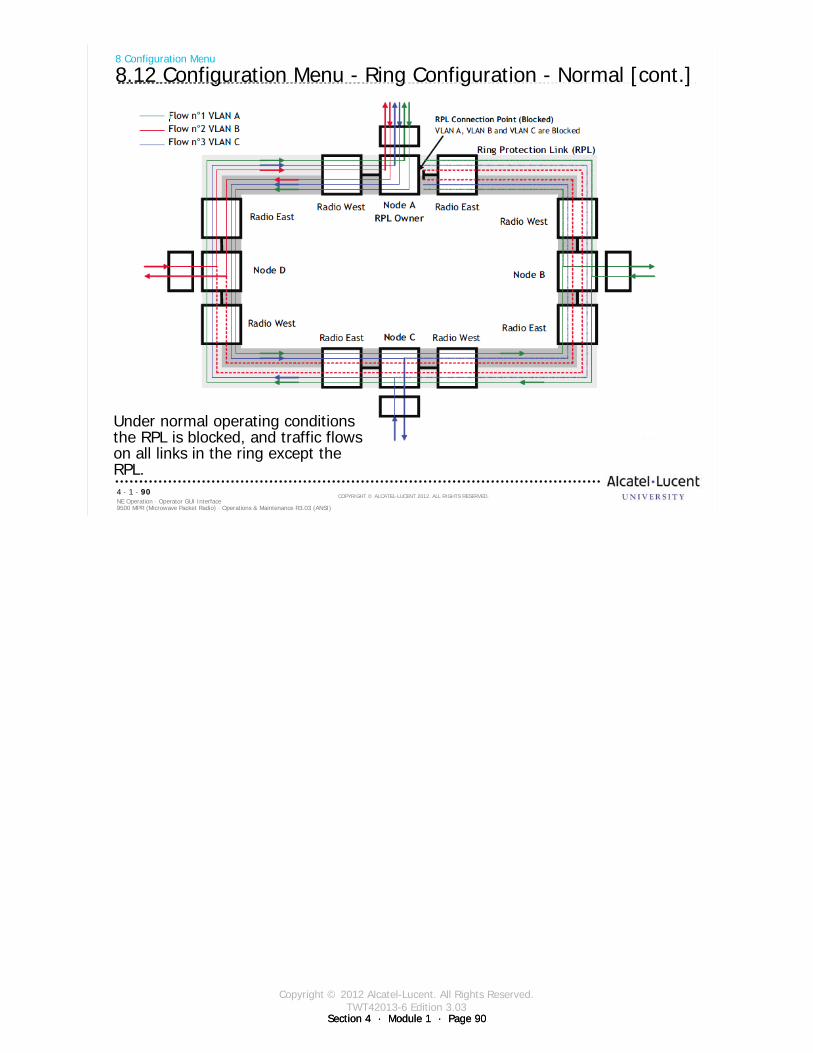
Copyright © 2012 Alcatel-Lucent. All Rights Reserved.TWT42013-6 Edition 3.03
Section 4 · Module 1 · Page 90Section 4 · Module 1 · Page 90
9500 MPR (Microwave Packet Radio) · Operations & Maintenance R3.03 (ANSI)NE Operation · Operator GUI Interface4 · 1 · 90
COPYRIGHT © ALCATEL-LUCENT 2012. ALL RIGHTS RESERVED.
8 Configuration Menu
8.12 Configuration Menu - Ring Configuration - Normal [cont.]
Under normal operating conditions the RPL is blocked, and traffic flows on all links in the ring except the RPL.
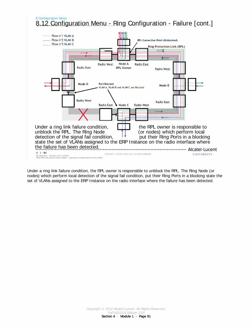
Copyright © 2012 Alcatel-Lucent. All Rights Reserved.TWT42013-6 Edition 3.03
Section 4 · Module 1 · Page 91Section 4 · Module 1 · Page 91
9500 MPR (Microwave Packet Radio) · Operations & Maintenance R3.03 (ANSI)NE Operation · Operator GUI Interface4 · 1 · 91
COPYRIGHT © ALCATEL-LUCENT 2012. ALL RIGHTS RESERVED.
8 Configuration Menu
8.12 Configuration Menu - Ring Configuration - Failure [cont.]
Under a ring link failure condition, the RPL owner is responsible to unblock the RPL. The Ring Node (or nodes) which perform local detection of the signal fail condition, put their Ring Ports in a blocking state the set of VLANs assigned to the ERP Instance on the radio interface where the failure has been detected.
Under a ring link failure condition, the RPL owner is responsible to unblock the RPL. The Ring Node (or nodes) which perform local detection of the signal fail condition, put their Ring Ports in a blocking state the set of VLANs assigned to the ERP Instance on the radio interface where the failure has been detected.
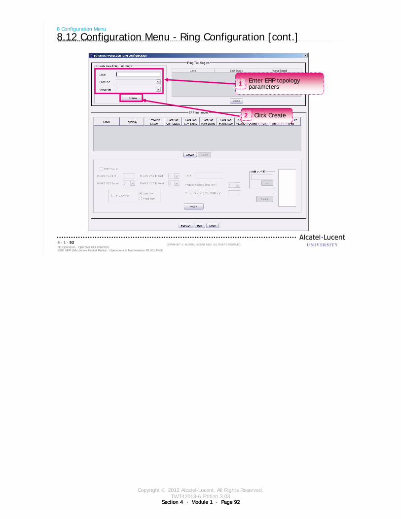
Copyright © 2012 Alcatel-Lucent. All Rights Reserved.TWT42013-6 Edition 3.03
Section 4 · Module 1 · Page 92Section 4 · Module 1 · Page 92
9500 MPR (Microwave Packet Radio) · Operations & Maintenance R3.03 (ANSI)NE Operation · Operator GUI Interface4 · 1 · 92
COPYRIGHT © ALCATEL-LUCENT 2012. ALL RIGHTS RESERVED.
8 Configuration Menu
8.12 Configuration Menu - Ring Configuration [cont.]
Enter ERP topology parameters1
Click Create2
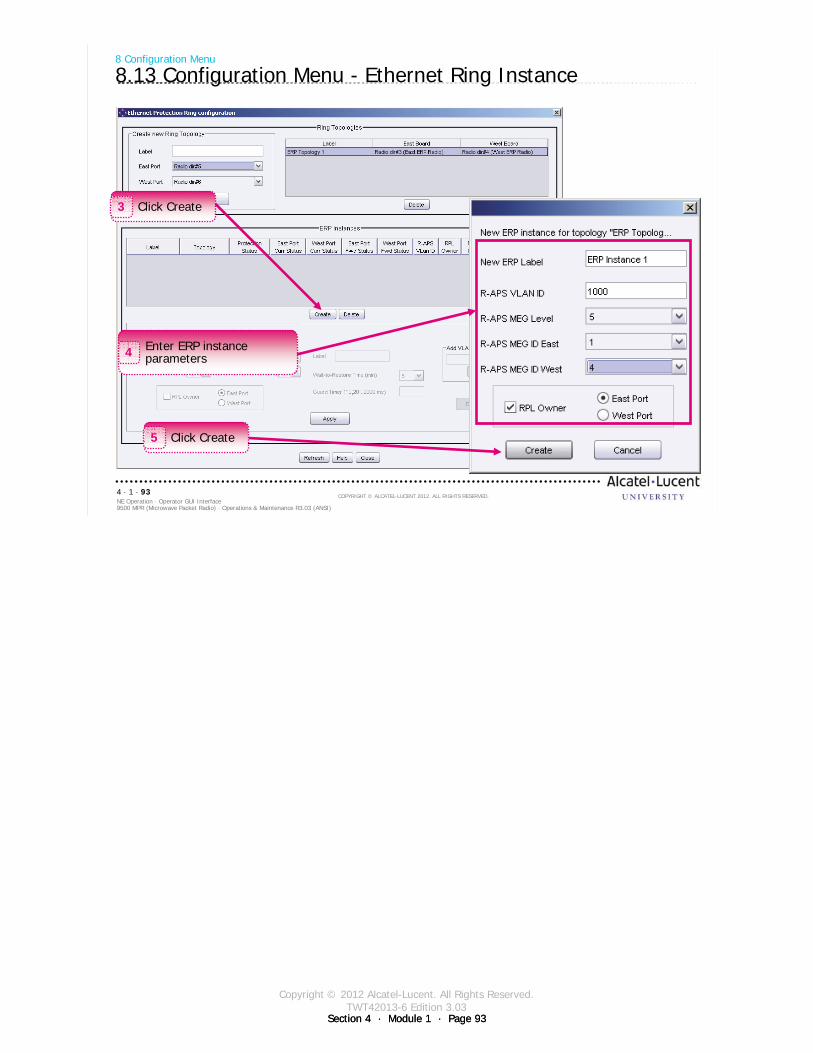
Copyright © 2012 Alcatel-Lucent. All Rights Reserved.TWT42013-6 Edition 3.03
Section 4 · Module 1 · Page 93Section 4 · Module 1 · Page 93
9500 MPR (Microwave Packet Radio) · Operations & Maintenance R3.03 (ANSI)NE Operation · Operator GUI Interface4 · 1 · 93
COPYRIGHT © ALCATEL-LUCENT 2012. ALL RIGHTS RESERVED.
8 Configuration Menu
8.13 Configuration Menu - Ethernet Ring Instance
Enter ERP instance parameters4
Click Create3
Click Create5
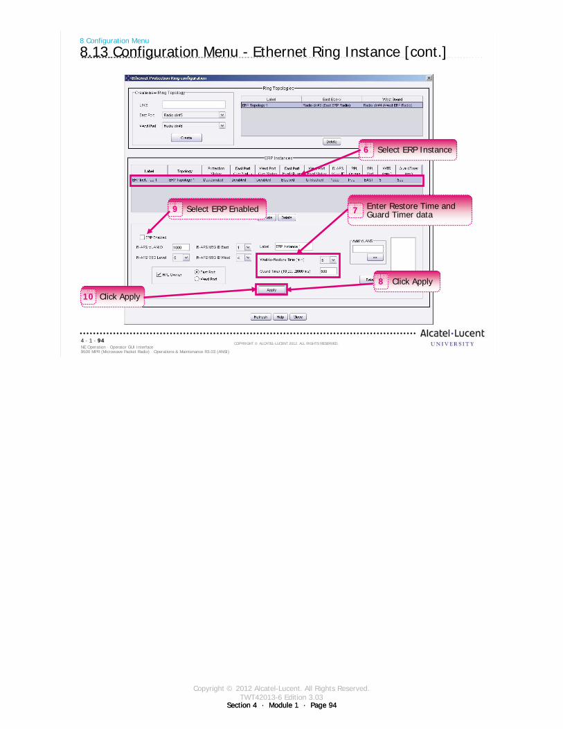
Copyright © 2012 Alcatel-Lucent. All Rights Reserved.TWT42013-6 Edition 3.03
Section 4 · Module 1 · Page 94Section 4 · Module 1 · Page 94
9500 MPR (Microwave Packet Radio) · Operations & Maintenance R3.03 (ANSI)NE Operation · Operator GUI Interface4 · 1 · 94
COPYRIGHT © ALCATEL-LUCENT 2012. ALL RIGHTS RESERVED.
8 Configuration Menu
8.13 Configuration Menu - Ethernet Ring Instance [cont.]
Select ERP Instance6
Enter Restore Time and Guard Timer data7
Click Apply8
Select ERP Enabled9
Click Apply10

Copyright © 2012 Alcatel-Lucent. All Rights Reserved.TWT42013-6 Edition 3.03
Section 4 · Module 1 · Page 95Section 4 · Module 1 · Page 95
9500 MPR (Microwave Packet Radio) · Operations & Maintenance R3.03 (ANSI)NE Operation · Operator GUI Interface4 · 1 · 95
COPYRIGHT © ALCATEL-LUCENT 2012. ALL RIGHTS RESERVED.
8 Configuration Menu
8.14 Configuration Menu - LAG Configuration
Refer to 9500 MPR Operation and Administration, 3EM23954AHAA, DLP-140 for more details
Select Configuration>Lag configuration1
Ethernet and Radio LAG ports are provisioned using the Craft Terminal.
Ethernet and Radio ports must be configured prior to provisioning LAG ports.
Use the menu or the icon to setup Lag configuration.
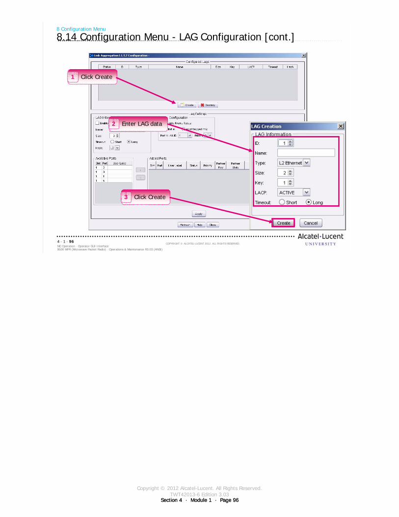
Copyright © 2012 Alcatel-Lucent. All Rights Reserved.TWT42013-6 Edition 3.03
Section 4 · Module 1 · Page 96Section 4 · Module 1 · Page 96
9500 MPR (Microwave Packet Radio) · Operations & Maintenance R3.03 (ANSI)NE Operation · Operator GUI Interface4 · 1 · 96
COPYRIGHT © ALCATEL-LUCENT 2012. ALL RIGHTS RESERVED.
8 Configuration Menu
8.14 Configuration Menu - LAG Configuration [cont.]
Click Create1
Click Create3
Enter LAG data2
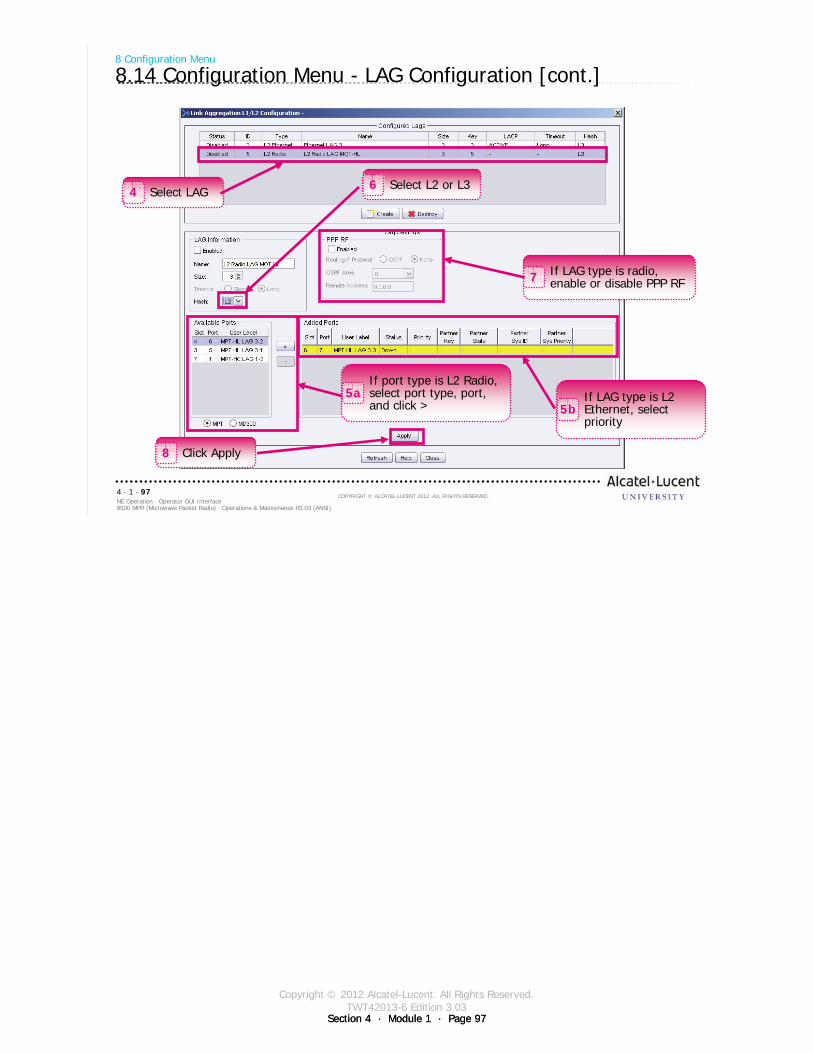
Copyright © 2012 Alcatel-Lucent. All Rights Reserved.TWT42013-6 Edition 3.03
Section 4 · Module 1 · Page 97Section 4 · Module 1 · Page 97
9500 MPR (Microwave Packet Radio) · Operations & Maintenance R3.03 (ANSI)NE Operation · Operator GUI Interface4 · 1 · 97
COPYRIGHT © ALCATEL-LUCENT 2012. ALL RIGHTS RESERVED.
8 Configuration Menu
8.14 Configuration Menu - LAG Configuration [cont.]
Select LAG4
If port type is L2 Radio, select port type, port, and click >
5a If LAG type is L2 Ethernet, select priority
5b
Select L2 or L36
If LAG type is radio, enable or disable PPP RF7
Click Apply8
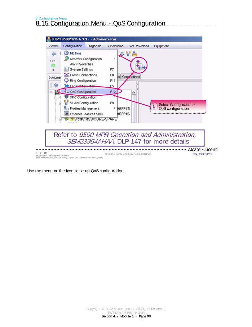
Copyright © 2012 Alcatel-Lucent. All Rights Reserved.TWT42013-6 Edition 3.03
Section 4 · Module 1 · Page 98Section 4 · Module 1 · Page 98
9500 MPR (Microwave Packet Radio) · Operations & Maintenance R3.03 (ANSI)NE Operation · Operator GUI Interface4 · 1 · 98
COPYRIGHT © ALCATEL-LUCENT 2012. ALL RIGHTS RESERVED.
8 Configuration Menu
8.15 Configuration Menu - QoS Configuration
Refer to 9500 MPR Operation and Administration, 3EM23954AHAA, DLP-147 for more details
Select Configuration>QoS configuration1
Use the menu or the icon to setup QoS configuration.
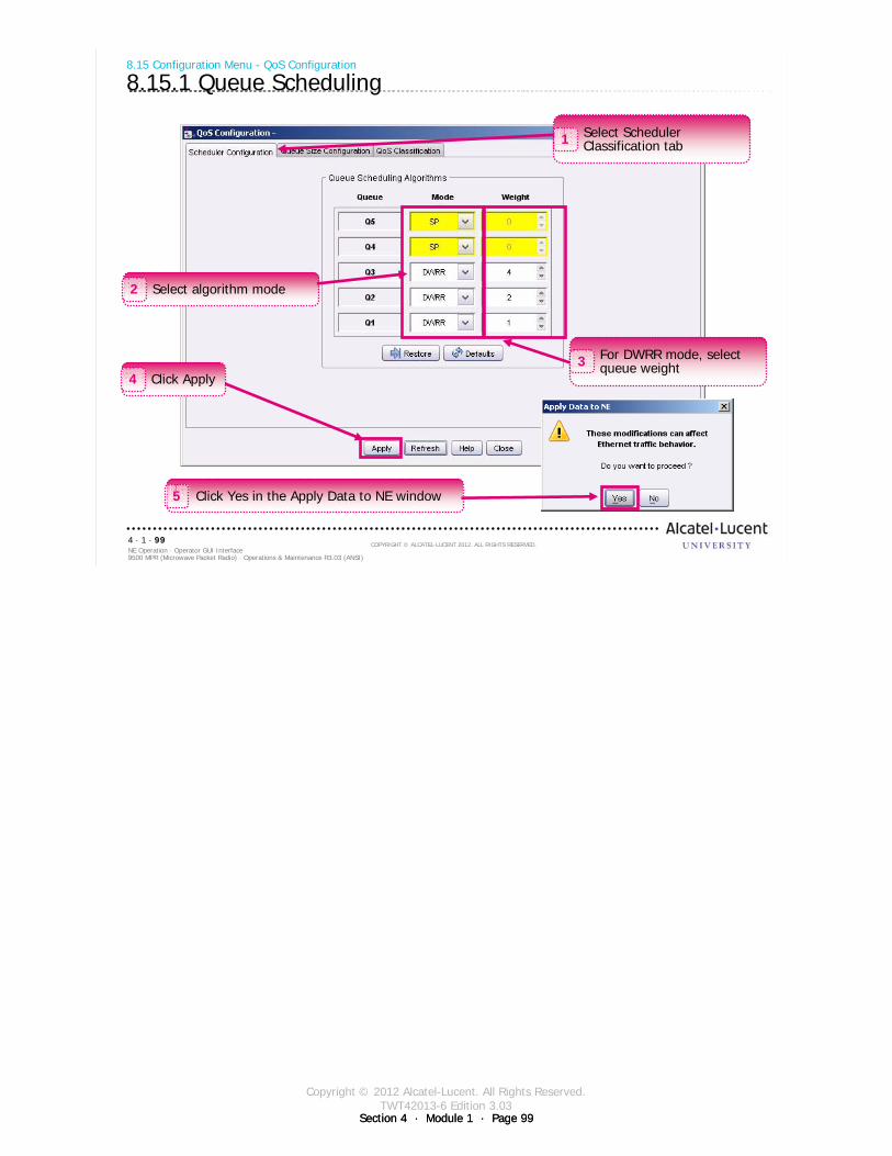
Copyright © 2012 Alcatel-Lucent. All Rights Reserved.TWT42013-6 Edition 3.03
Section 4 · Module 1 · Page 99Section 4 · Module 1 · Page 99
9500 MPR (Microwave Packet Radio) · Operations & Maintenance R3.03 (ANSI)NE Operation · Operator GUI Interface4 · 1 · 99
COPYRIGHT © ALCATEL-LUCENT 2012. ALL RIGHTS RESERVED.
8.15 Configuration Menu - QoS Configuration
8.15.1 Queue Scheduling
Select Scheduler Classification tab1
Select algorithm mode2
For DWRR mode, select queue weight3
Click Apply4
Click Yes in the Apply Data to NE window5

Copyright © 2012 Alcatel-Lucent. All Rights Reserved.TWT42013-6 Edition 3.03
Section 4 · Module 1 · Page 100Section 4 · Module 1 · Page 100
9500 MPR (Microwave Packet Radio) · Operations & Maintenance R3.03 (ANSI)NE Operation · Operator GUI Interface4 · 1 · 100
COPYRIGHT © ALCATEL-LUCENT 2012. ALL RIGHTS RESERVED.
8.15 Configuration Menu - QoS Configuration
8.15.2 Queue Size
Select Queue Size Configuration tab1
Double-click cell and enter data2
Modified queue size values shown in yellow
Click Apply3
Click Yes in the Apply Data to NE window4
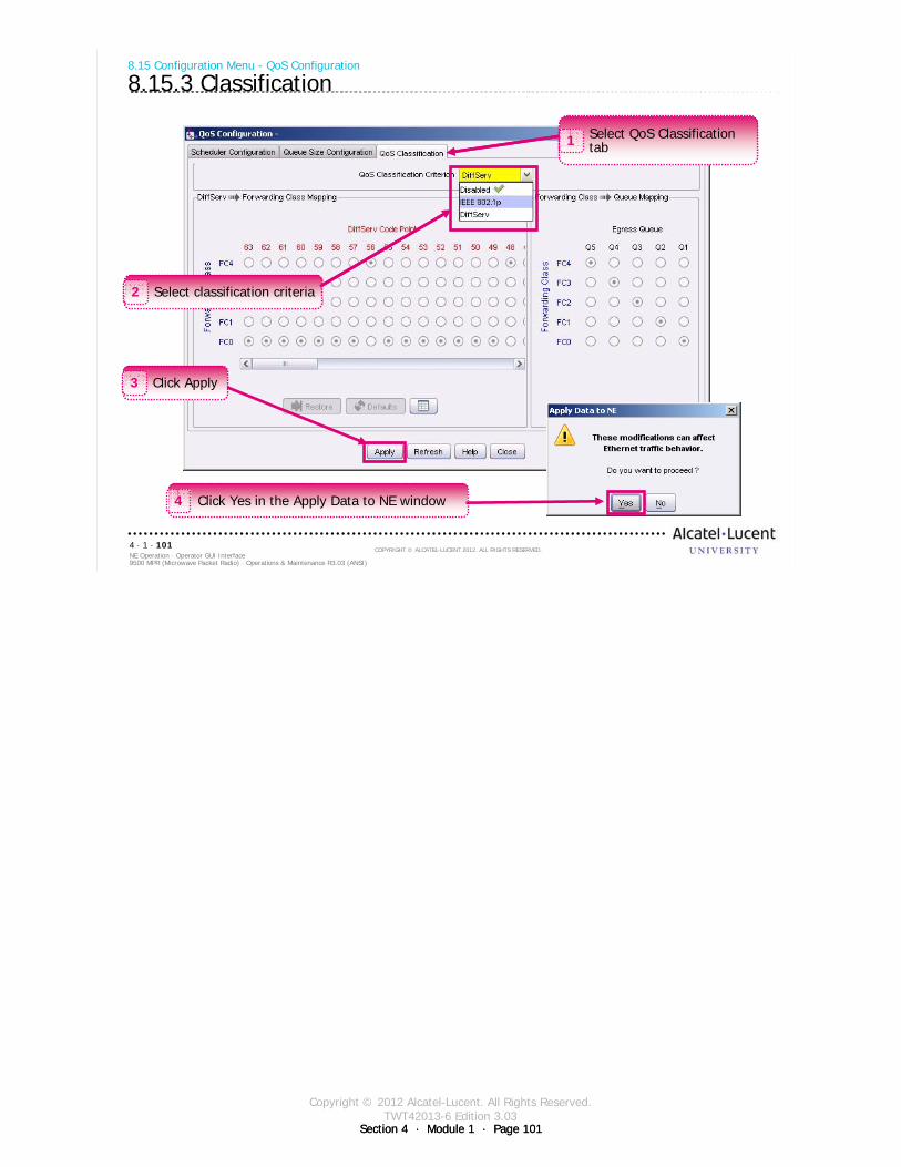
Copyright © 2012 Alcatel-Lucent. All Rights Reserved.TWT42013-6 Edition 3.03
Section 4 · Module 1 · Page 101Section 4 · Module 1 · Page 101
9500 MPR (Microwave Packet Radio) · Operations & Maintenance R3.03 (ANSI)NE Operation · Operator GUI Interface4 · 1 · 101
COPYRIGHT © ALCATEL-LUCENT 2012. ALL RIGHTS RESERVED.
8.15 Configuration Menu - QoS Configuration
8.15.3 Classification
Select QoS Classification tab1
Select classification criteria2
Click Apply3
Select QoS Classification tab1
Select classification criteria2
Click Apply3
Click Yes in the Apply Data to NE window4
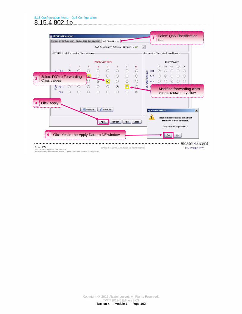
Copyright © 2012 Alcatel-Lucent. All Rights Reserved.TWT42013-6 Edition 3.03
Section 4 · Module 1 · Page 102Section 4 · Module 1 · Page 102
9500 MPR (Microwave Packet Radio) · Operations & Maintenance R3.03 (ANSI)NE Operation · Operator GUI Interface4 · 1 · 102
COPYRIGHT © ALCATEL-LUCENT 2012. ALL RIGHTS RESERVED.
8.15 Configuration Menu - QoS Configuration
8.15.4 802.1p
Select QoS Classification tab1
Select PCP to Forwarding Class values2
Click Apply3
Modified forwarding class values shown in yellow
Click Yes in the Apply Data to NE window4
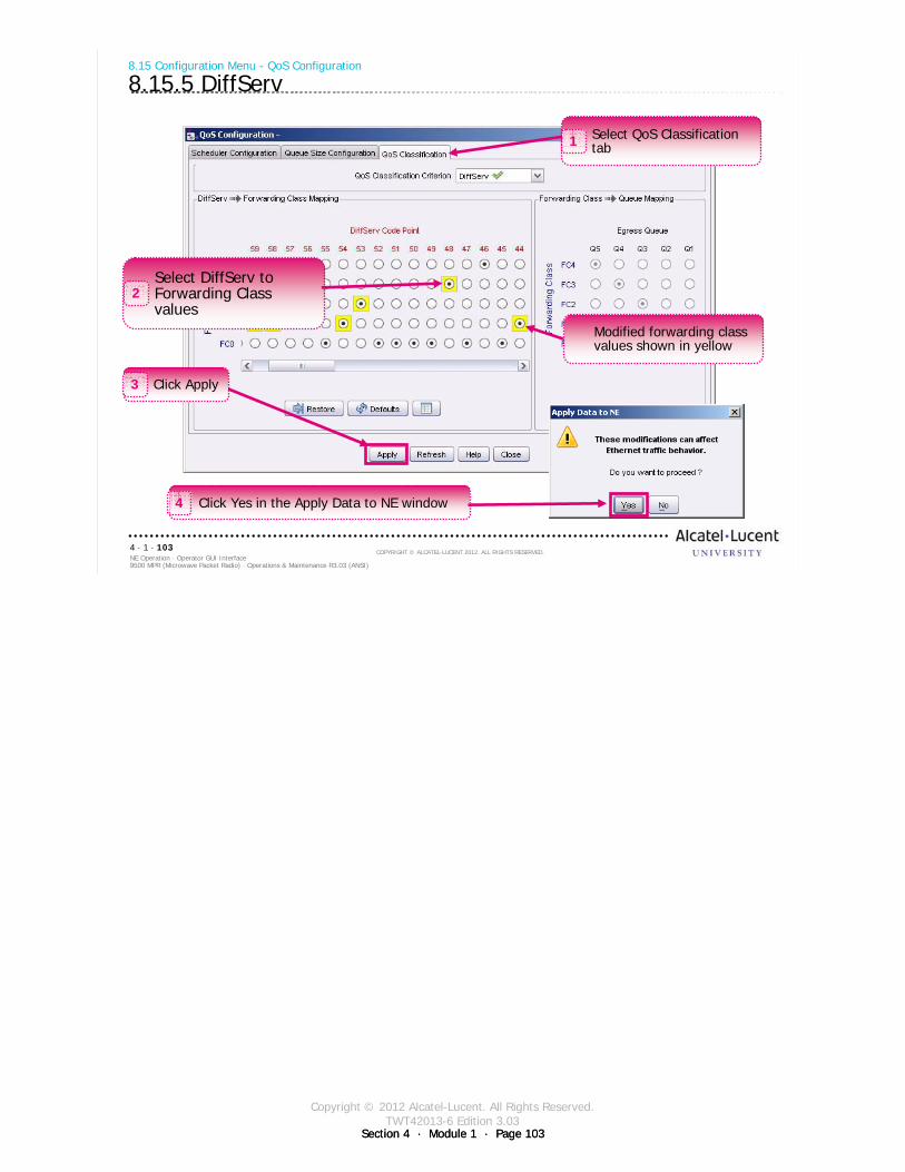
Copyright © 2012 Alcatel-Lucent. All Rights Reserved.TWT42013-6 Edition 3.03
Section 4 · Module 1 · Page 103Section 4 · Module 1 · Page 103
9500 MPR (Microwave Packet Radio) · Operations & Maintenance R3.03 (ANSI)NE Operation · Operator GUI Interface4 · 1 · 103
COPYRIGHT © ALCATEL-LUCENT 2012. ALL RIGHTS RESERVED.
8.15 Configuration Menu - QoS Configuration
8.15.5 DiffServ
Select QoS Classification tab1
Select DiffServ to Forwarding Class values
2
Click Apply3
Modified forwarding class values shown in yellow
Click Yes in the Apply Data to NE window4
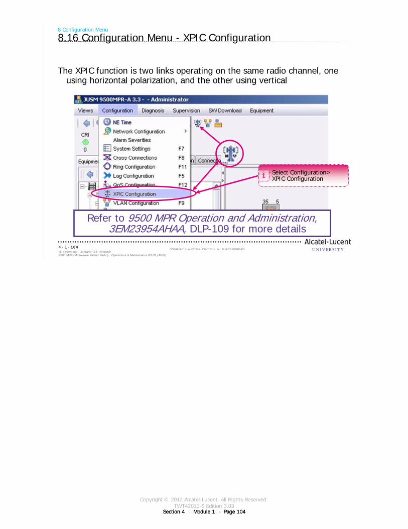
Copyright © 2012 Alcatel-Lucent. All Rights Reserved.TWT42013-6 Edition 3.03
Section 4 · Module 1 · Page 104Section 4 · Module 1 · Page 104
9500 MPR (Microwave Packet Radio) · Operations & Maintenance R3.03 (ANSI)NE Operation · Operator GUI Interface4 · 1 · 104
COPYRIGHT © ALCATEL-LUCENT 2012. ALL RIGHTS RESERVED.
8 Configuration Menu
8.16 Configuration Menu - XPIC Configuration
The XPIC function is two links operating on the same radio channel, one using horizontal polarization, and the other using vertical
Select Configuration>XPIC Configuration1
Refer to 9500 MPR Operation and Administration, 3EM23954AHAA, DLP-109 for more details
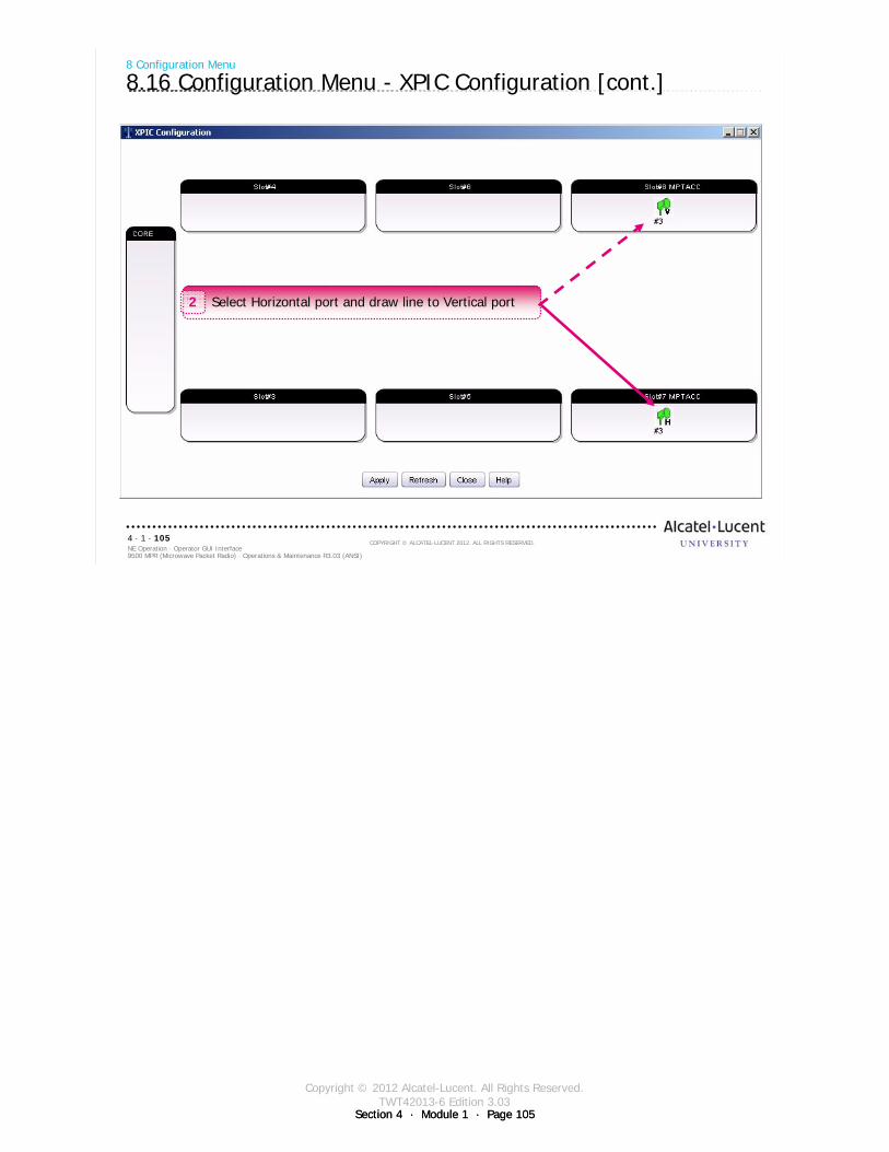
Copyright © 2012 Alcatel-Lucent. All Rights Reserved.TWT42013-6 Edition 3.03
Section 4 · Module 1 · Page 105Section 4 · Module 1 · Page 105
9500 MPR (Microwave Packet Radio) · Operations & Maintenance R3.03 (ANSI)NE Operation · Operator GUI Interface4 · 1 · 105
COPYRIGHT © ALCATEL-LUCENT 2012. ALL RIGHTS RESERVED.
8 Configuration Menu
8.16 Configuration Menu - XPIC Configuration [cont.]
Select Horizontal port and draw line to Vertical port2
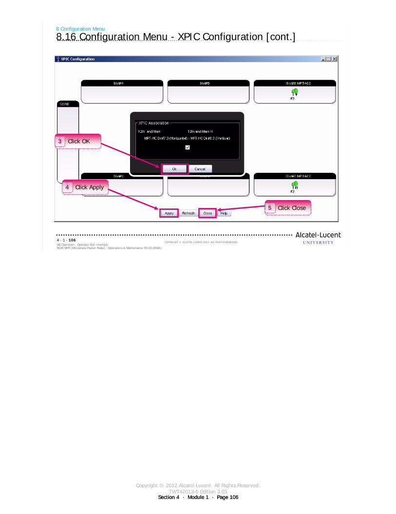
Copyright © 2012 Alcatel-Lucent. All Rights Reserved.TWT42013-6 Edition 3.03
Section 4 · Module 1 · Page 106Section 4 · Module 1 · Page 106
9500 MPR (Microwave Packet Radio) · Operations & Maintenance R3.03 (ANSI)NE Operation · Operator GUI Interface4 · 1 · 106
COPYRIGHT © ALCATEL-LUCENT 2012. ALL RIGHTS RESERVED.
8 Configuration Menu
8.16 Configuration Menu - XPIC Configuration [cont.]
Click OK3
Click Apply4
Click Close5
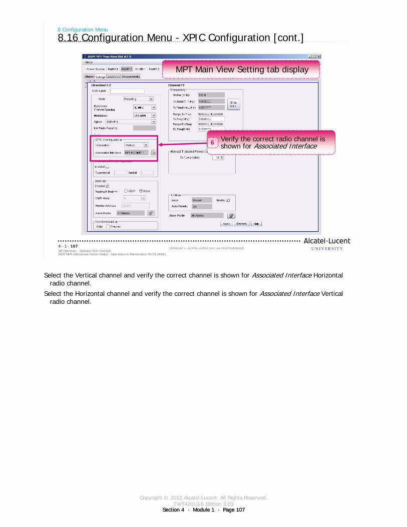
Copyright © 2012 Alcatel-Lucent. All Rights Reserved.TWT42013-6 Edition 3.03
Section 4 · Module 1 · Page 107Section 4 · Module 1 · Page 107
9500 MPR (Microwave Packet Radio) · Operations & Maintenance R3.03 (ANSI)NE Operation · Operator GUI Interface4 · 1 · 107
COPYRIGHT © ALCATEL-LUCENT 2012. ALL RIGHTS RESERVED.
8 Configuration Menu
8.16 Configuration Menu - XPIC Configuration [cont.]
Verify the correct radio channel is shown for Associated Interface6
MPT Main View Setting tab display
Select the Vertical channel and verify the correct channel is shown for Associated Interface Horizontal radio channel.
Select the Horizontal channel and verify the correct channel is shown for Associated Interface Vertical radio channel.
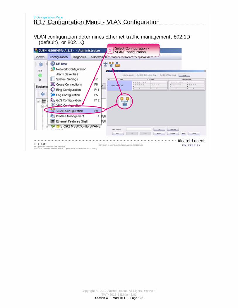
Copyright © 2012 Alcatel-Lucent. All Rights Reserved.TWT42013-6 Edition 3.03
Section 4 · Module 1 · Page 108Section 4 · Module 1 · Page 108
9500 MPR (Microwave Packet Radio) · Operations & Maintenance R3.03 (ANSI)NE Operation · Operator GUI Interface4 · 1 · 108
COPYRIGHT © ALCATEL-LUCENT 2012. ALL RIGHTS RESERVED.
8 Configuration Menu
8.17 Configuration Menu - VLAN Configuration
VLAN configuration determines Ethernet traffic management, 802.1D (default), or 802.1Q
Select Configuration>VLAN Configuration1
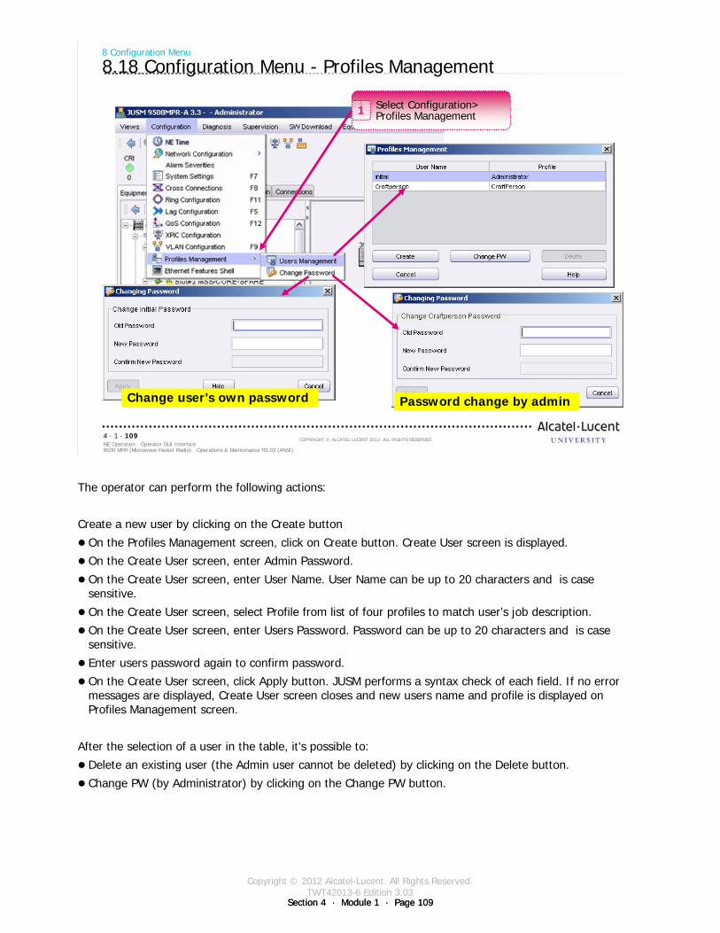
Copyright © 2012 Alcatel-Lucent. All Rights Reserved.TWT42013-6 Edition 3.03
Section 4 · Module 1 · Page 109Section 4 · Module 1 · Page 109
9500 MPR (Microwave Packet Radio) · Operations & Maintenance R3.03 (ANSI)NE Operation · Operator GUI Interface4 · 1 · 109
COPYRIGHT © ALCATEL-LUCENT 2012. ALL RIGHTS RESERVED.
8 Configuration Menu
8.18 Configuration Menu - Profiles Management
Select Configuration>Profiles Management1
Change user’s own password Password change by admin
The operator can perform the following actions:
Create a new user by clicking on the Create button
On the Profiles Management screen, click on Create button. Create User screen is displayed.
On the Create User screen, enter Admin Password.
On the Create User screen, enter User Name. User Name can be up to 20 characters and is case sensitive.
On the Create User screen, select Profile from list of four profiles to match user’s job description.
On the Create User screen, enter Users Password. Password can be up to 20 characters and is case sensitive.
Enter users password again to confirm password.
On the Create User screen, click Apply button. JUSM performs a syntax check of each field. If no error messages are displayed, Create User screen closes and new users name and profile is displayed on Profiles Management screen.
After the selection of a user in the table, it's possible to:
Delete an existing user (the Admin user cannot be deleted) by clicking on the Delete button.
Change PW (by Administrator) by clicking on the Change PW button.

Copyright © 2012 Alcatel-Lucent. All Rights Reserved.TWT42013-6 Edition 3.03
Section 4 · Module 1 · Page 110Section 4 · Module 1 · Page 110
9500 MPR (Microwave Packet Radio) · Operations & Maintenance R3.03 (ANSI)NE Operation · Operator GUI Interface4 · 1 · 110
COPYRIGHT © ALCATEL-LUCENT 2012. ALL RIGHTS RESERVED.
8 Configuration Menu
8.19 Configuration Menu - Ethernet Features Shell
The LAG can be created by CLI commands launched with the WebEML from the menu Configuration > Ethernet Features Shell
Select Configuration>Ethernet Features Shell1
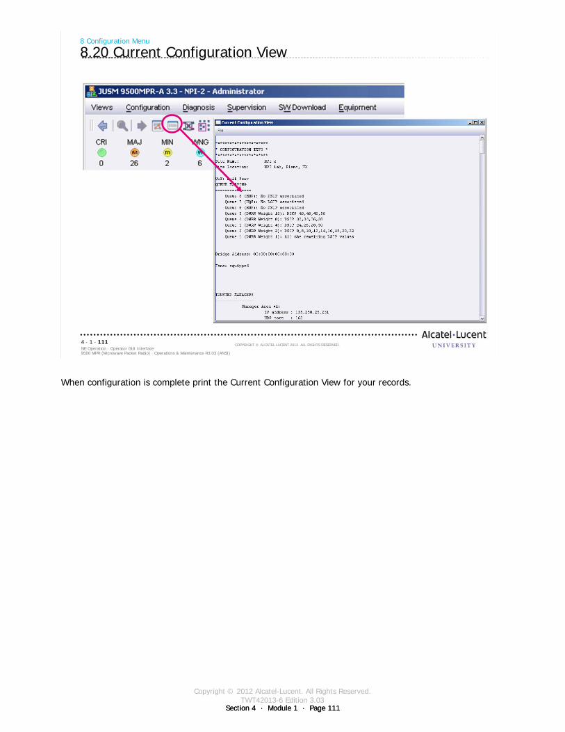
Copyright © 2012 Alcatel-Lucent. All Rights Reserved.TWT42013-6 Edition 3.03
Section 4 · Module 1 · Page 111Section 4 · Module 1 · Page 111
9500 MPR (Microwave Packet Radio) · Operations & Maintenance R3.03 (ANSI)NE Operation · Operator GUI Interface4 · 1 · 111
COPYRIGHT © ALCATEL-LUCENT 2012. ALL RIGHTS RESERVED.
8 Configuration Menu
8.20 Current Configuration View
When configuration is complete print the Current Configuration View for your records.

Copyright © 2012 Alcatel-Lucent. All Rights Reserved.TWT42013-6 Edition 3.03
Section 4 · Module 1 · Page 112Section 4 · Module 1 · Page 112
9500 MPR (Microwave Packet Radio) · Operations & Maintenance R3.03 (ANSI)NE Operation · Operator GUI Interface4 · 1 · 112
COPYRIGHT © ALCATEL-LUCENT 2012. ALL RIGHTS RESERVED.
Blank page
Switch to notes view!
This page intentionally left blank

Copyright © 2012 Alcatel-Lucent. All Rights Reserved.TWT42013-6 Edition 3.03
Section 4 · Module 1 · Page 113
9500 MPR (Microwave Packet Radio) · Operations & Maintenance R3.03 (ANSI)NE Operation · Operator GUI Interface4 · 1 · 113
COPYRIGHT © ALCATEL-LUCENT 2012. ALL RIGHTS RESERVED.
9 Supervision Menu
Refer to 9500 MPR Operation and Administration, 3EM23954AG DLP-136 for more details
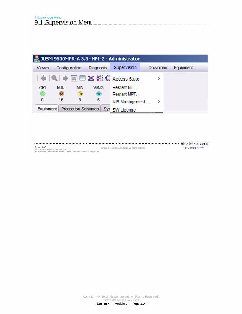
Copyright © 2012 Alcatel-Lucent. All Rights Reserved.TWT42013-6 Edition 3.03
Section 4 · Module 1 · Page 114Section 4 · Module 1 · Page 114
9500 MPR (Microwave Packet Radio) · Operations & Maintenance R3.03 (ANSI)NE Operation · Operator GUI Interface4 · 1 · 114
COPYRIGHT © ALCATEL-LUCENT 2012. ALL RIGHTS RESERVED.
9 Supervision Menu
9.1 Supervision Menu
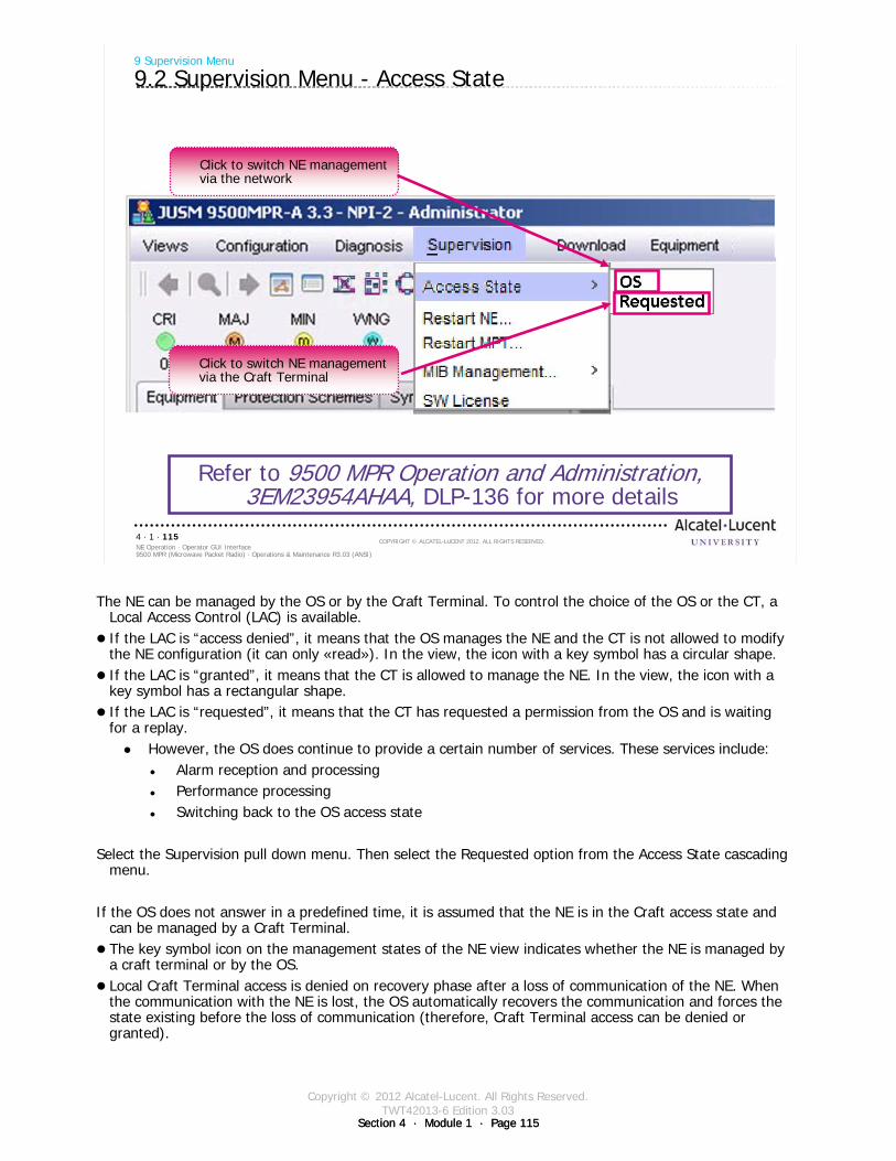
Copyright © 2012 Alcatel-Lucent. All Rights Reserved.TWT42013-6 Edition 3.03
Section 4 · Module 1 · Page 115Section 4 · Module 1 · Page 115
9500 MPR (Microwave Packet Radio) · Operations & Maintenance R3.03 (ANSI)NE Operation · Operator GUI Interface4 · 1 · 115
COPYRIGHT © ALCATEL-LUCENT 2012. ALL RIGHTS RESERVED.
9 Supervision Menu
9.2 Supervision Menu - Access State
Refer to 9500 MPR Operation and Administration, 3EM23954AHAA, DLP-136 for more details
Click to switch NE management via the network
Click to switch NE management via the Craft Terminal
The NE can be managed by the OS or by the Craft Terminal. To control the choice of the OS or the CT, a Local Access Control (LAC) is available.If the LAC is “access denied”, it means that the OS manages the NE and the CT is not allowed to modify the NE configuration (it can only «read»). In the view, the icon with a key symbol has a circular shape.If the LAC is “granted”, it means that the CT is allowed to manage the NE. In the view, the icon with a key symbol has a rectangular shape. If the LAC is “requested”, it means that the CT has requested a permission from the OS and is waiting for a replay.
However, the OS does continue to provide a certain number of services. These services include:Alarm reception and processingPerformance processingSwitching back to the OS access state
Select the Supervision pull down menu. Then select the Requested option from the Access State cascading menu.
If the OS does not answer in a predefined time, it is assumed that the NE is in the Craft access state and can be managed by a Craft Terminal.The key symbol icon on the management states of the NE view indicates whether the NE is managed by a craft terminal or by the OS.Local Craft Terminal access is denied on recovery phase after a loss of communication of the NE. When the communication with the NE is lost, the OS automatically recovers the communication and forces the state existing before the loss of communication (therefore, Craft Terminal access can be denied or granted).
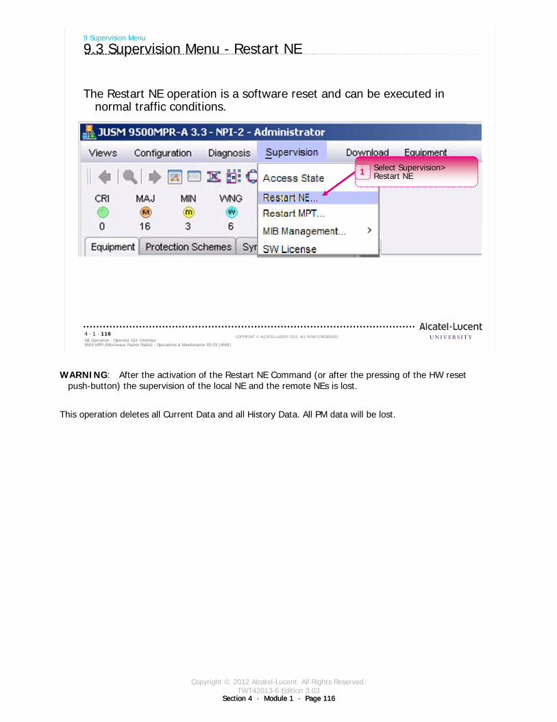
Copyright © 2012 Alcatel-Lucent. All Rights Reserved.TWT42013-6 Edition 3.03
Section 4 · Module 1 · Page 116Section 4 · Module 1 · Page 116
9500 MPR (Microwave Packet Radio) · Operations & Maintenance R3.03 (ANSI)NE Operation · Operator GUI Interface4 · 1 · 116
COPYRIGHT © ALCATEL-LUCENT 2012. ALL RIGHTS RESERVED.
The Restart NE operation is a software reset and can be executed in normal traffic conditions.
9 Supervision Menu
9.3 Supervision Menu - Restart NE
Select Supervision>Restart NE1
WARNING: After the activation of the Restart NE Command (or after the pressing of the HW reset push-button) the supervision of the local NE and the remote NEs is lost.
This operation deletes all Current Data and all History Data. All PM data will be lost.
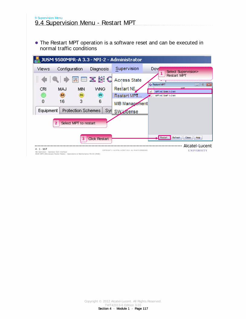
Copyright © 2012 Alcatel-Lucent. All Rights Reserved.TWT42013-6 Edition 3.03
Section 4 · Module 1 · Page 117Section 4 · Module 1 · Page 117
9500 MPR (Microwave Packet Radio) · Operations & Maintenance R3.03 (ANSI)NE Operation · Operator GUI Interface4 · 1 · 117
COPYRIGHT © ALCATEL-LUCENT 2012. ALL RIGHTS RESERVED.
The Restart MPT operation is a software reset and can be executed in normal traffic conditions
9 Supervision Menu
9.4 Supervision Menu - Restart MPT
Select MPT to restart2
Select Supervision>Restart MPT1
Click Restart3
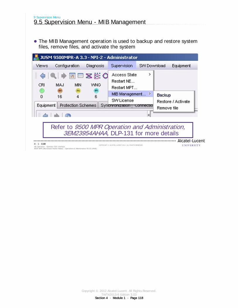
Copyright © 2012 Alcatel-Lucent. All Rights Reserved.TWT42013-6 Edition 3.03
Section 4 · Module 1 · Page 118Section 4 · Module 1 · Page 118
9500 MPR (Microwave Packet Radio) · Operations & Maintenance R3.03 (ANSI)NE Operation · Operator GUI Interface4 · 1 · 118
COPYRIGHT © ALCATEL-LUCENT 2012. ALL RIGHTS RESERVED.
9 Supervision Menu
9.5 Supervision Menu - MIB Management
The MIB Management operation is used to backup and restore system files, remove files, and activate the system
Refer to 9500 MPR Operation and Administration, 3EM23954AHAA, DLP-131 for more details
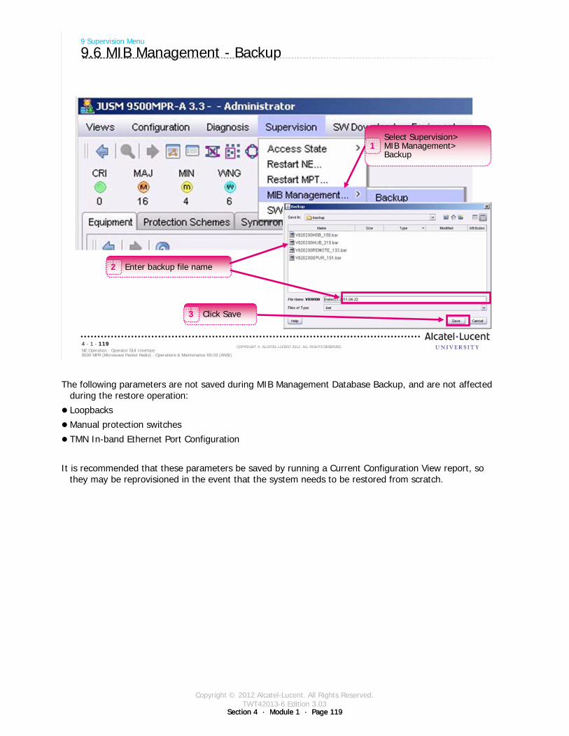
Copyright © 2012 Alcatel-Lucent. All Rights Reserved.TWT42013-6 Edition 3.03
Section 4 · Module 1 · Page 119Section 4 · Module 1 · Page 119
9500 MPR (Microwave Packet Radio) · Operations & Maintenance R3.03 (ANSI)NE Operation · Operator GUI Interface4 · 1 · 119
COPYRIGHT © ALCATEL-LUCENT 2012. ALL RIGHTS RESERVED.
9 Supervision Menu
9.6 MIB Management - Backup
Select Supervision>MIB Management>Backup
1
Enter backup file name2
Click Save3
The following parameters are not saved during MIB Management Database Backup, and are not affected during the restore operation:
Loopbacks
Manual protection switches
TMN In-band Ethernet Port Configuration
It is recommended that these parameters be saved by running a Current Configuration View report, so they may be reprovisioned in the event that the system needs to be restored from scratch.
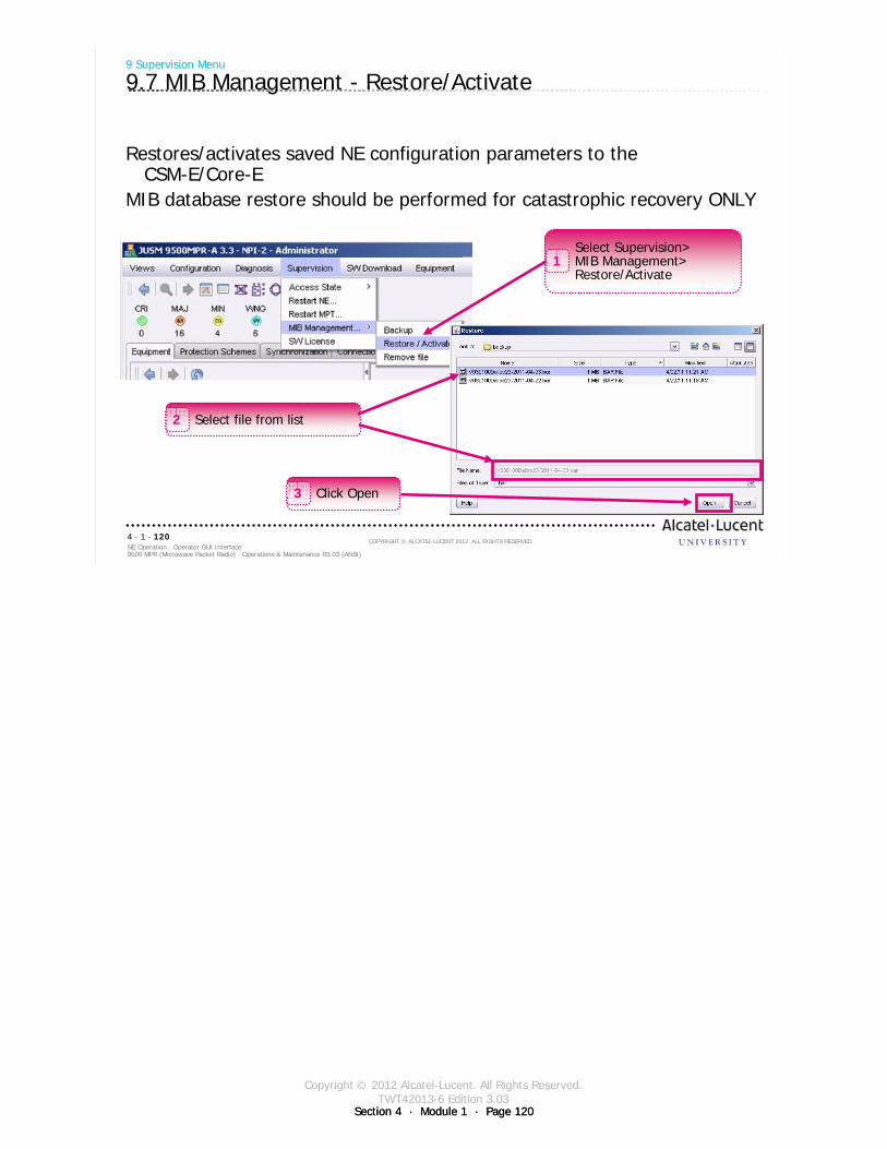
Copyright © 2012 Alcatel-Lucent. All Rights Reserved.TWT42013-6 Edition 3.03
Section 4 · Module 1 · Page 120Section 4 · Module 1 · Page 120
9500 MPR (Microwave Packet Radio) · Operations & Maintenance R3.03 (ANSI)NE Operation · Operator GUI Interface4 · 1 · 120
COPYRIGHT © ALCATEL-LUCENT 2012. ALL RIGHTS RESERVED.
9 Supervision Menu
9.7 MIB Management - Restore/Activate
Restores/activates saved NE configuration parameters to the CSM-E/Core-E
MIB database restore should be performed for catastrophic recovery ONLY
Select Supervision>MIB Management>Restore/Activate
1
Select file from list2
Click Open3
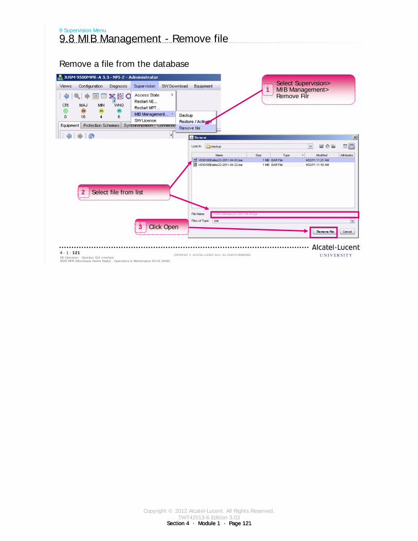
Copyright © 2012 Alcatel-Lucent. All Rights Reserved.TWT42013-6 Edition 3.03
Section 4 · Module 1 · Page 121Section 4 · Module 1 · Page 121
9500 MPR (Microwave Packet Radio) · Operations & Maintenance R3.03 (ANSI)NE Operation · Operator GUI Interface4 · 1 · 121
COPYRIGHT © ALCATEL-LUCENT 2012. ALL RIGHTS RESERVED.
Remove a file from the database
9 Supervision Menu
9.8 MIB Management - Remove file
Select Supervision>MIB Management>Remove Filr
1
Click Open3
Select file from list2
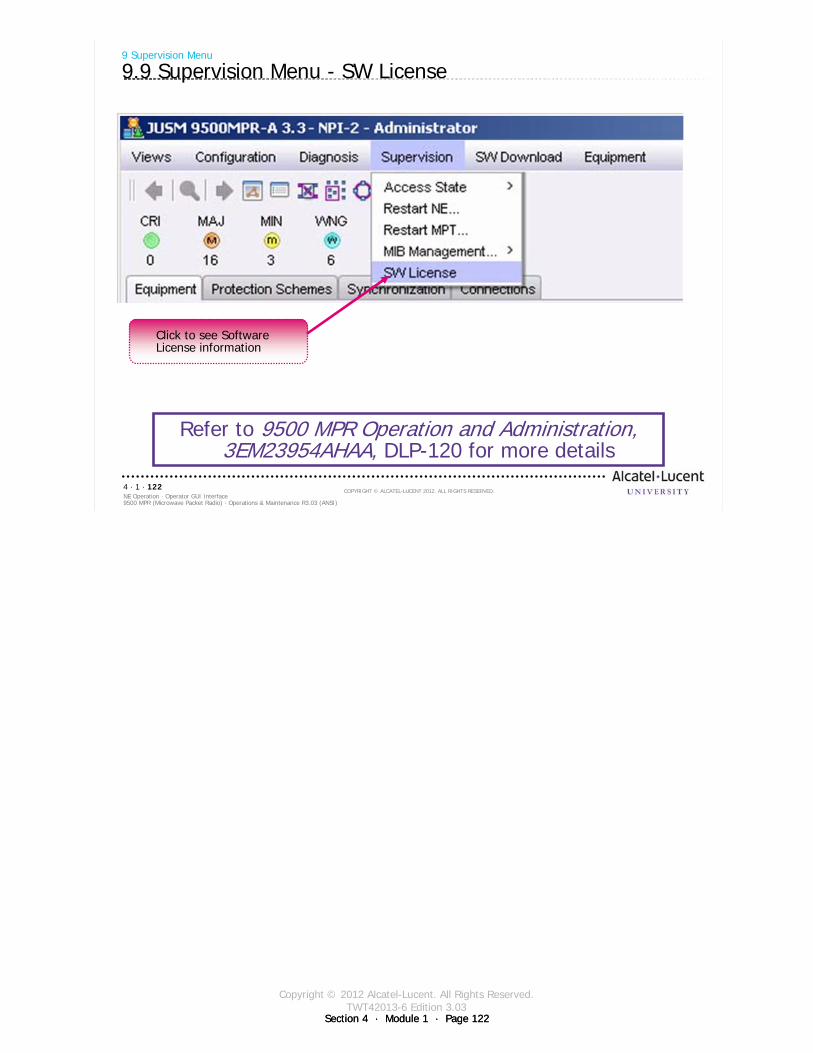
Copyright © 2012 Alcatel-Lucent. All Rights Reserved.TWT42013-6 Edition 3.03
Section 4 · Module 1 · Page 122Section 4 · Module 1 · Page 122
9500 MPR (Microwave Packet Radio) · Operations & Maintenance R3.03 (ANSI)NE Operation · Operator GUI Interface4 · 1 · 122
COPYRIGHT © ALCATEL-LUCENT 2012. ALL RIGHTS RESERVED.
Refer to 9500 MPR Operation and Administration, 3EM23954AHAA, DLP-120 for more details
9 Supervision Menu
9.9 Supervision Menu - SW License
Click to see Software License information
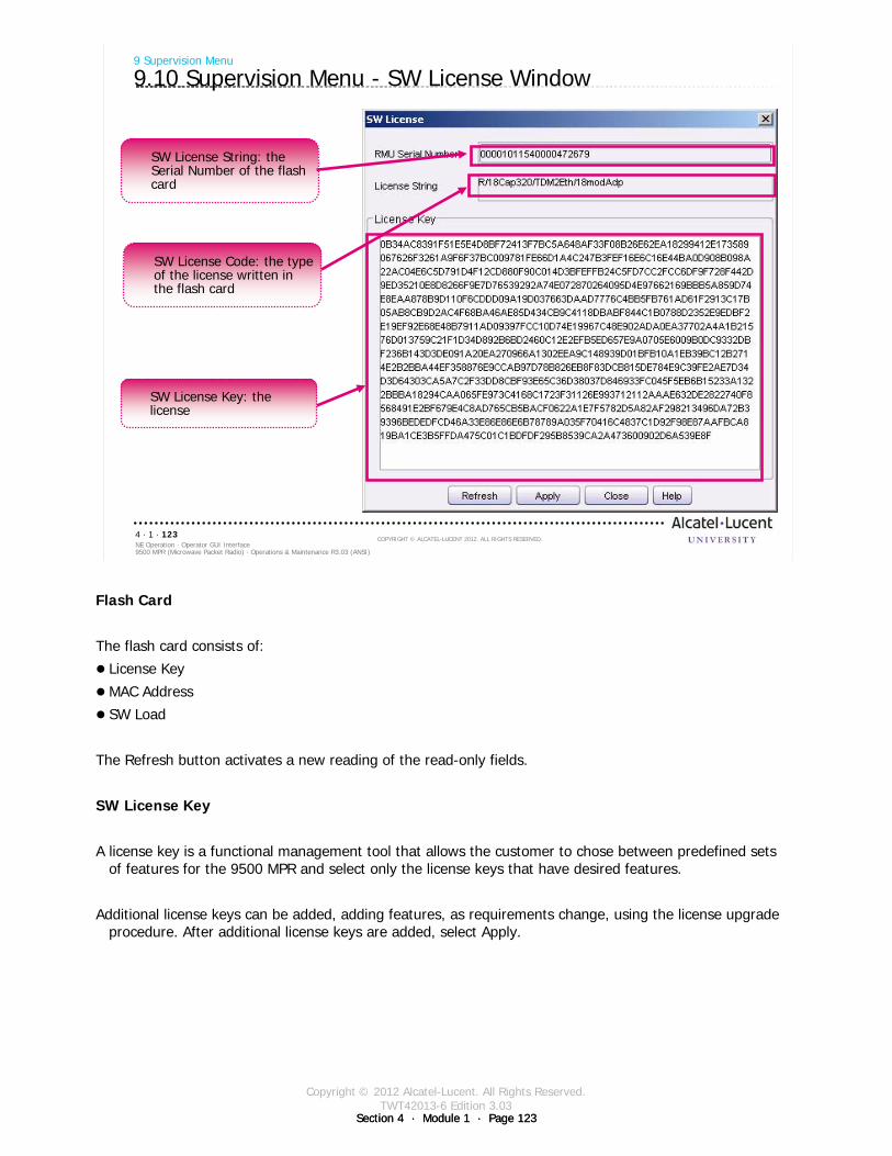
Copyright © 2012 Alcatel-Lucent. All Rights Reserved.TWT42013-6 Edition 3.03
Section 4 · Module 1 · Page 123Section 4 · Module 1 · Page 123
9500 MPR (Microwave Packet Radio) · Operations & Maintenance R3.03 (ANSI)NE Operation · Operator GUI Interface4 · 1 · 123
COPYRIGHT © ALCATEL-LUCENT 2012. ALL RIGHTS RESERVED.
9 Supervision Menu
9.10 Supervision Menu - SW License Window
SW License String: the Serial Number of the flash card
SW License Code: the type of the license written in the flash card
SW License Key: the license
Flash Card
The flash card consists of:
License Key
MAC Address
SW Load
The Refresh button activates a new reading of the read-only fields.
SW License Key
A license key is a functional management tool that allows the customer to chose between predefined sets of features for the 9500 MPR and select only the license keys that have desired features.
Additional license keys can be added, adding features, as requirements change, using the license upgrade procedure. After additional license keys are added, select Apply.

Copyright © 2012 Alcatel-Lucent. All Rights Reserved.TWT42013-6 Edition 3.03
Section 4 · Module 1 · Page 124Section 4 · Module 1 · Page 124
9500 MPR (Microwave Packet Radio) · Operations & Maintenance R3.03 (ANSI)NE Operation · Operator GUI Interface4 · 1 · 124
COPYRIGHT © ALCATEL-LUCENT 2012. ALL RIGHTS RESERVED.
Blank page
Switch to notes view!
This page intentionally left blank
Copyright © 2012 Alcatel-Lucent. All Rights Reserved.TWT42013-6 Edition 3.03
Section 4 · Module 1 · Page 125
9500 MPR (Microwave Packet Radio) · Operations & Maintenance R3.03 (ANSI)NE Operation · Operator GUI Interface4 · 1 · 125
COPYRIGHT © ALCATEL-LUCENT 2012. ALL RIGHTS RESERVED.
10 Software Download Menu
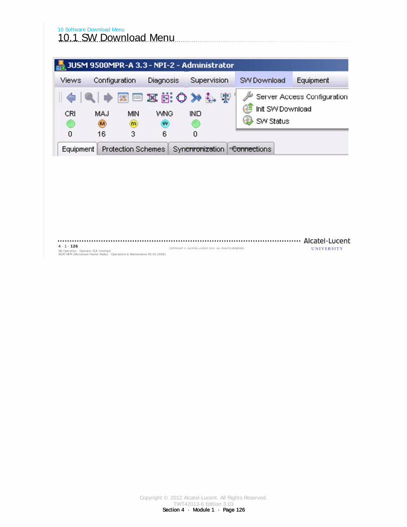
Copyright © 2012 Alcatel-Lucent. All Rights Reserved.TWT42013-6 Edition 3.03
Section 4 · Module 1 · Page 126Section 4 · Module 1 · Page 126
9500 MPR (Microwave Packet Radio) · Operations & Maintenance R3.03 (ANSI)NE Operation · Operator GUI Interface4 · 1 · 126
COPYRIGHT © ALCATEL-LUCENT 2012. ALL RIGHTS RESERVED.
10 Software Download Menu
10.1 SW Download Menu
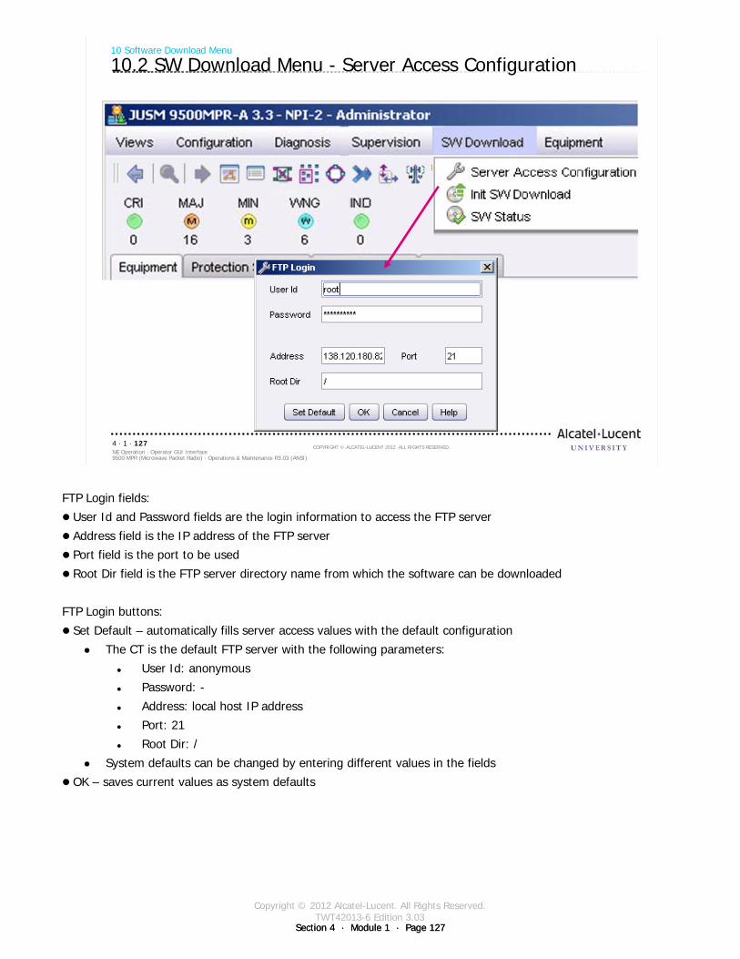
Copyright © 2012 Alcatel-Lucent. All Rights Reserved.TWT42013-6 Edition 3.03
Section 4 · Module 1 · Page 127Section 4 · Module 1 · Page 127
9500 MPR (Microwave Packet Radio) · Operations & Maintenance R3.03 (ANSI)NE Operation · Operator GUI Interface4 · 1 · 127
COPYRIGHT © ALCATEL-LUCENT 2012. ALL RIGHTS RESERVED.
10 Software Download Menu
10.2 SW Download Menu - Server Access Configuration
FTP Login fields:
User Id and Password fields are the login information to access the FTP server
Address field is the IP address of the FTP server
Port field is the port to be used
Root Dir field is the FTP server directory name from which the software can be downloaded
FTP Login buttons:
Set Default – automatically fills server access values with the default configuration
The CT is the default FTP server with the following parameters:
User Id: anonymous
Password: -
Address: local host IP address
Port: 21
Root Dir: /
System defaults can be changed by entering different values in the fields
OK – saves current values as system defaults

Copyright © 2012 Alcatel-Lucent. All Rights Reserved.TWT42013-6 Edition 3.03
Section 4 · Module 1 · Page 128Section 4 · Module 1 · Page 128
9500 MPR (Microwave Packet Radio) · Operations & Maintenance R3.03 (ANSI)NE Operation · Operator GUI Interface4 · 1 · 128
COPYRIGHT © ALCATEL-LUCENT 2012. ALL RIGHTS RESERVED.
10 Software Download Menu
10.3 SW Download Menu - Init SW Download
Download software to the NE to upgrade the NE software version
FTP Server Address is from the last overhead regarding Server Access Configuration
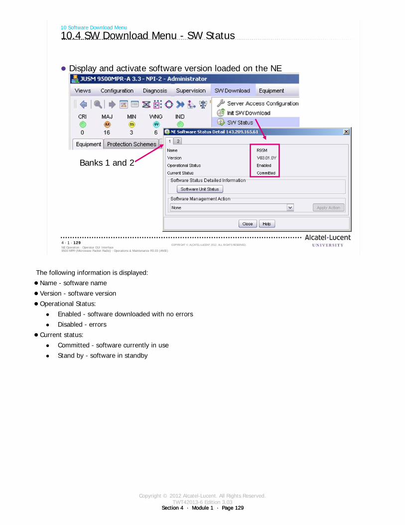
Copyright © 2012 Alcatel-Lucent. All Rights Reserved.TWT42013-6 Edition 3.03
Section 4 · Module 1 · Page 129Section 4 · Module 1 · Page 129
9500 MPR (Microwave Packet Radio) · Operations & Maintenance R3.03 (ANSI)NE Operation · Operator GUI Interface4 · 1 · 129
COPYRIGHT © ALCATEL-LUCENT 2012. ALL RIGHTS RESERVED.
Display and activate software version loaded on the NE
10 Software Download Menu
10.4 SW Download Menu - SW Status
Banks 1 and 2
The following information is displayed:
Name - software name
Version - software version
Operational Status:
Enabled - software downloaded with no errors
Disabled - errors
Current status:
Committed - software currently in use
Stand by - software in standby
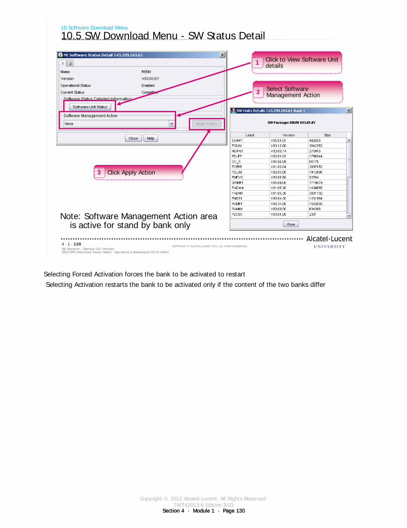
Copyright © 2012 Alcatel-Lucent. All Rights Reserved.TWT42013-6 Edition 3.03
Section 4 · Module 1 · Page 130Section 4 · Module 1 · Page 130
9500 MPR (Microwave Packet Radio) · Operations & Maintenance R3.03 (ANSI)NE Operation · Operator GUI Interface4 · 1 · 130
COPYRIGHT © ALCATEL-LUCENT 2012. ALL RIGHTS RESERVED.
10 Software Download Menu
10.5 SW Download Menu - SW Status Detail
Note: Software Management Action area is active for stand by bank only
Click to View Software Unit details1
Select Software Management Action2
Click Apply Action3
Selecting Forced Activation forces the bank to be activated to restart
Selecting Activation restarts the bank to be activated only if the content of the two banks differ
Copyright © 2012 Alcatel-Lucent. All Rights Reserved.TWT42013-6 Edition 3.03
Section 4 · Module 1 · Page 131Section 4 · Module 1 · Page 131
9500 MPR (Microwave Packet Radio) · Operations & Maintenance R3.03 (ANSI)NE Operation · Operator GUI Interface4 · 1 · 131
COPYRIGHT © ALCATEL-LUCENT 2012. ALL RIGHTS RESERVED.
Exercise Time allowed:
Lab Exercise 2Operator GUI - NEtO Overview
Lab Exercise 3Operator GUI - NE Main View
Lab Exercise 4Operator GUI - NEtO Menus
Lab Exercise 5MPT-HL and MOD300 Configuration

Copyright © 2012 Alcatel-Lucent. All Rights Reserved.TWT42013-6 Edition 3.03
Section 4 · Module 1 · Page 132Section 4 · Module 1 · Page 132
9500 MPR (Microwave Packet Radio) · Operations & Maintenance R3.03 (ANSI)NE Operation · Operator GUI Interface4 · 1 · 132
COPYRIGHT © ALCATEL-LUCENT 2012. ALL RIGHTS RESERVED.
Blank page
Switch to notes view!
This page intentionally left blank

Copyright © 2012 Alcatel-Lucent. All Rights Reserved.TWT42013-6 Edition 3.03
Section 4 · Module 1 · Page 133Section 4 · Module 1 · Page 133
9500 MPR (Microwave Packet Radio) · Operations & Maintenance R3.03 (ANSI)NE Operation · Operator GUI Interface4 · 1 · 133
COPYRIGHT © ALCATEL-LUCENT 2012. ALL RIGHTS RESERVED.
Module summary
NEtO applicationConnect to a 9500 MPR-A either via a network connection
or directly to the NMS (Craft) terminal9500 MPR-A Network Elements
Tool BarsAlarm & State PanelsEquipment TabProtection TabSynchronization TabConnections TabMPT-HL SettingsRadio Modem SettingsLocal ConfigurationNTP Configuration
IP ConfigurationIP Static Routing ConfigurationOSPF Area ConfigurationSystem SettingsCross-ConnectionsSW LicenseServer Access ConfigurationInit SW DownloadSW Status

Copyright © 2012 Alcatel-Lucent. All Rights Reserved.TWT42013-6 Edition 3.03
Section 4 · Module 1 · Page 134Section 4 · Module 1 · Page 134
9500 MPR (Microwave Packet Radio) · Operations & Maintenance R3.03 (ANSI)NE Operation · Operator GUI Interface4 · 1 · 134
COPYRIGHT © ALCATEL-LUCENT 2012. ALL RIGHTS RESERVED.
End of moduleOperator GUI Interface

Copyright © 2012 Alcatel-Lucent. All Rights Reserved.TWT42013-7 Edition 3.03
Section 4 · Module 2 · Page 1
Do not delete this graphic elements in here:
All Rights Reserved © Alcatel-Lucent @@YEAR
Module 2Cross Connections
TWT42013-7 Edition 3.03
Section 4NE Operation
9500 MPR (Microwave Packet Radio)Operations & Maintenance R3.03 (ANSI)
TWT42013 Edition 1.1
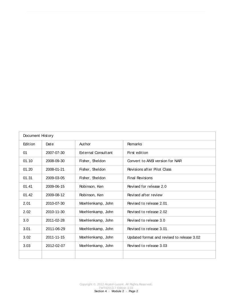
Copyright © 2012 Alcatel-Lucent. All Rights Reserved.TWT42013-7 Edition 3.03
Section 4 · Module 2 · Page 2
9500 MPR (Microwave Packet Radio) · Operations & Maintenance R3.03 (ANSI)NE Operation · Cross Connections4 · 2 · 2
COPYRIGHT © ALCATEL-LUCENT 2012. ALL RIGHTS RESERVED.
Blank page
This page is left blank intentionally
Revised to release 3.03Moehlenkamp, John2012-02-073.03
Document History
Edition Date Author Remarks
01 2007-07-30 External Consultant First edition
01.10 2008-09-30 Fisher, Sheldon Convert to ANSI version for NAR
01.20 2008-01-21 Fisher, Sheldon Revisions after Pilot Class
01.31 2009-03-05 Fisher, Sheldon Final Revisions
01.41 2009-06-15 Robinson, Ken Revised for release 2.0
01.42 2009-08-12 Robinson, Ken Revised after review
2.01 2010-07-30 Moehlenkamp, John Revised to release 2.01
2.02 2010-11-30 Moehlenkamp, John Revised to release 2.02
3.0 2011-02-28 Moehlenkamp, John Revised to release 3.0
3.01 2011-06-29 Moehlenkamp, John Revised to release 3.01
3.02 2011-11-15 Moehlenkamp, John Updated format and revised to release 3.02
Copyright © 2012 Alcatel-Lucent. All Rights Reserved.TWT42013-7 Edition 3.03
Section 4 · Module 2 · Page 3
9500 MPR (Microwave Packet Radio) · Operations & Maintenance R3.03 (ANSI)NE Operation · Cross Connections4 · 2 · 3
COPYRIGHT © ALCATEL-LUCENT 2012. ALL RIGHTS RESERVED.
Module objectives
Upon completion of this module, you should be able to:
Configure DS1 portsConfigure DS3 portsDescribe cross-connectionsTDM2TDM ModeTDM2Eth ModeTDM2TDMoEth ModeConfigure DS1 cross-connectionsConfigure DS3 cross-connectionsConfigure Ethernet portsDescribe port segregation Configure Ethernet (P2P VLAN) cross-connectionsConfigure radio cross-connections

Copyright © 2012 Alcatel-Lucent. All Rights Reserved.TWT42013-7 Edition 3.03
Section 4 · Module 2 · Page 4
9500 MPR (Microwave Packet Radio) · Operations & Maintenance R3.03 (ANSI)NE Operation · Cross Connections4 · 2 · 4
COPYRIGHT © ALCATEL-LUCENT 2012. ALL RIGHTS RESERVED.
Module objectives [cont.]
This page is left blank intentionally
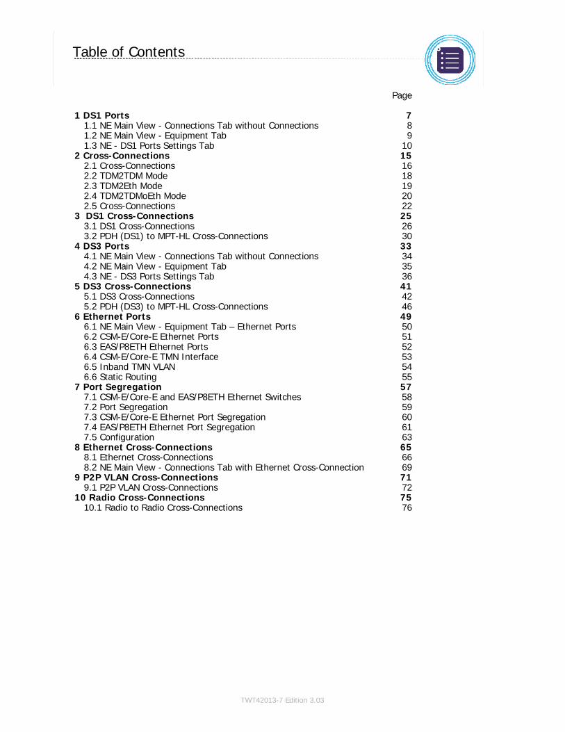
Copyright © 2012 Alcatel-Lucent. All Rights Reserved.TWT42013-7 Edition 3.03
9500 MPR (Microwave Packet Radio) · Operations & Maintenance R3.03 (ANSI)NE Operation · Cross Connections4 · 2 · 5
COPYRIGHT © ALCATEL-LUCENT 2012. ALL RIGHTS RESERVED.
Table of Contents
Switch to notes view! Page
1 DS1 Ports 71.1 NE Main View - Connections Tab without Connections 81.2 NE Main View - Equipment Tab 91.3 NE - DS1 Ports Settings Tab 10
2 Cross-Connections 152.1 Cross-Connections 162.2 TDM2TDM Mode 182.3 TDM2Eth Mode 192.4 TDM2TDMoEth Mode 202.5 Cross-Connections 22
3 DS1 Cross-Connections 253.1 DS1 Cross-Connections 263.2 PDH (DS1) to MPT-HL Cross-Connections 30
4 DS3 Ports 334.1 NE Main View - Connections Tab without Connections 344.2 NE Main View - Equipment Tab 354.3 NE - DS3 Ports Settings Tab 36
5 DS3 Cross-Connections 415.1 DS3 Cross-Connections 425.2 PDH (DS3) to MPT-HL Cross-Connections 46
6 Ethernet Ports 496.1 NE Main View - Equipment Tab – Ethernet Ports 506.2 CSM-E/Core-E Ethernet Ports 516.3 EAS/P8ETH Ethernet Ports 526.4 CSM-E/Core-E TMN Interface 536.5 Inband TMN VLAN 546.6 Static Routing 55
7 Port Segregation 577.1 CSM-E/Core-E and EAS/P8ETH Ethernet Switches 587.2 Port Segregation 597.3 CSM-E/Core-E Ethernet Port Segregation 607.4 EAS/P8ETH Ethernet Port Segregation 617.5 Configuration 63
8 Ethernet Cross-Connections 658.1 Ethernet Cross-Connections 668.2 NE Main View - Connections Tab with Ethernet Cross-Connection 69
9 P2P VLAN Cross-Connections 719.1 P2P VLAN Cross-Connections 72
10 Radio Cross-Connections 7510.1 Radio to Radio Cross-Connections 76

Copyright © 2012 Alcatel-Lucent. All Rights Reserved.TWT42013-7 Edition 3.03
9500 MPR (Microwave Packet Radio) · Operations & Maintenance R3.03 (ANSI)NE Operation · Cross Connections4 · 2 · 6
COPYRIGHT © ALCATEL-LUCENT 2012. ALL RIGHTS RESERVED.
Table of Contents [cont.]
Switch to notes view! Page

Copyright © 2012 Alcatel-Lucent. All Rights Reserved.TWT42013-7 Edition 3.03
Section 4 · Module 2 · Page 7
9500 MPR (Microwave Packet Radio) · Operations & Maintenance R3.03 (ANSI)NE Operation · Cross Connections4 · 2 · 7
COPYRIGHT © ALCATEL-LUCENT 2012. ALL RIGHTS RESERVED.
1 DS1 Ports
Refer to 9500 MPR Operation and Administration, 3EM23954AHAA, DLP-104 and DLP-106 for more
details
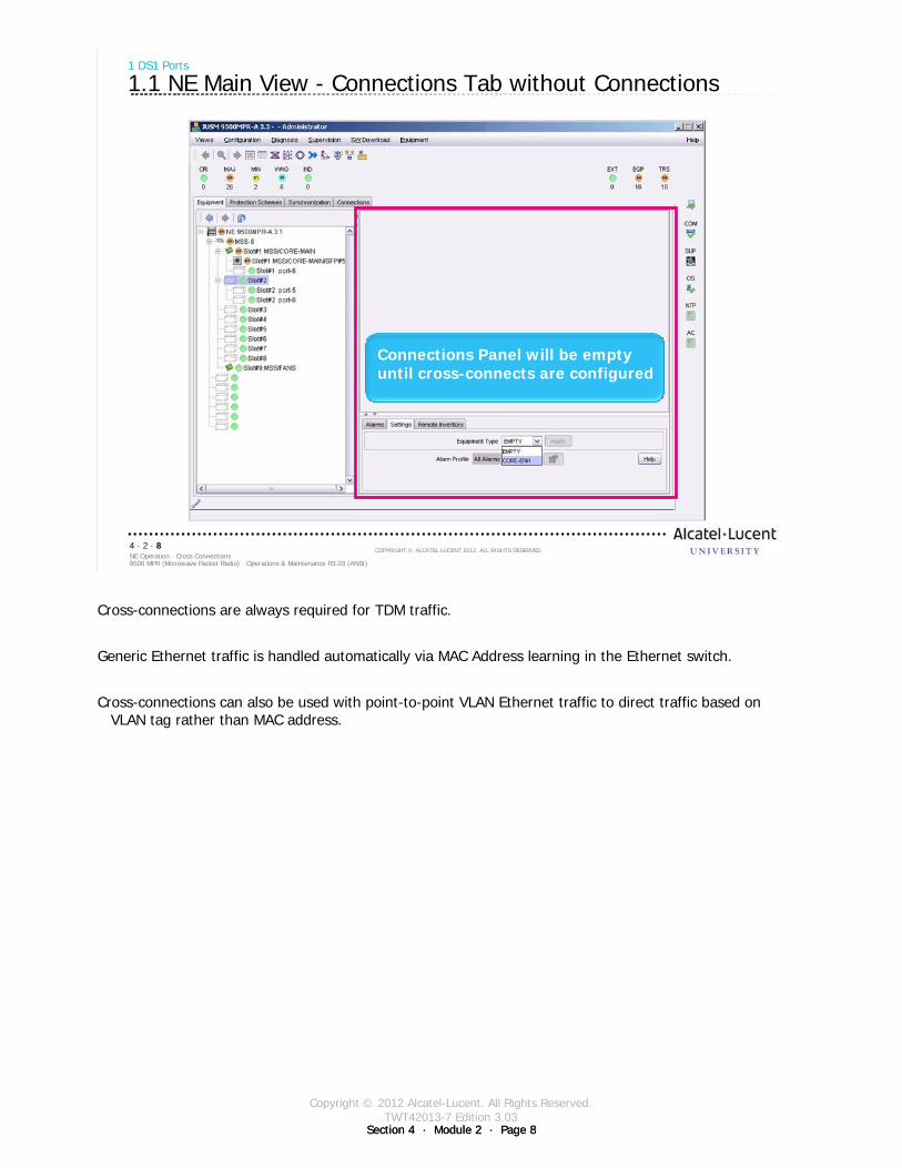
Copyright © 2012 Alcatel-Lucent. All Rights Reserved.TWT42013-7 Edition 3.03
Section 4 · Module 2 · Page 8Section 4 · Module 2 · Page 8
9500 MPR (Microwave Packet Radio) · Operations & Maintenance R3.03 (ANSI)NE Operation · Cross Connections4 · 2 · 8
COPYRIGHT © ALCATEL-LUCENT 2012. ALL RIGHTS RESERVED.
1 DS1 Ports
1.1 NE Main View - Connections Tab without Connections
Connections Panel will be empty until cross-connects are configured
Cross-connections are always required for TDM traffic.
Generic Ethernet traffic is handled automatically via MAC Address learning in the Ethernet switch.
Cross-connections can also be used with point-to-point VLAN Ethernet traffic to direct traffic based on VLAN tag rather than MAC address.
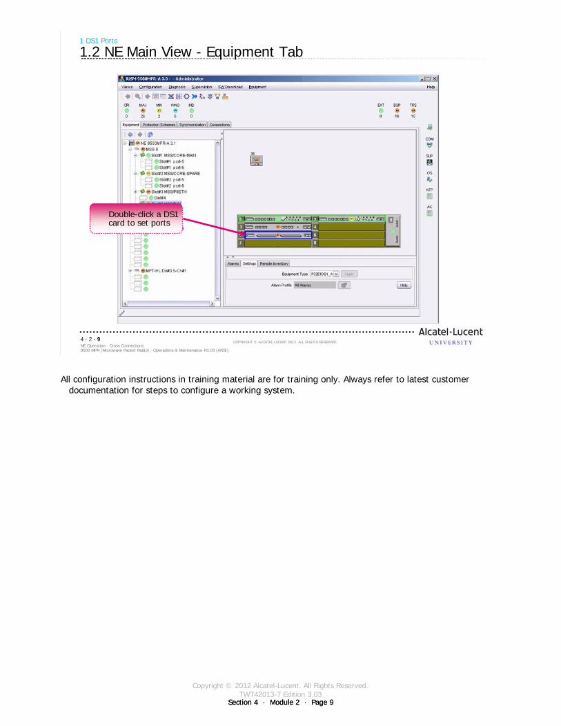
Copyright © 2012 Alcatel-Lucent. All Rights Reserved.TWT42013-7 Edition 3.03
Section 4 · Module 2 · Page 9Section 4 · Module 2 · Page 9
9500 MPR (Microwave Packet Radio) · Operations & Maintenance R3.03 (ANSI)NE Operation · Cross Connections4 · 2 · 9
COPYRIGHT © ALCATEL-LUCENT 2012. ALL RIGHTS RESERVED.
1 DS1 Ports
1.2 NE Main View - Equipment Tab
Double-click a DS1 card to set ports
All configuration instructions in training material are for training only. Always refer to latest customer documentation for steps to configure a working system.
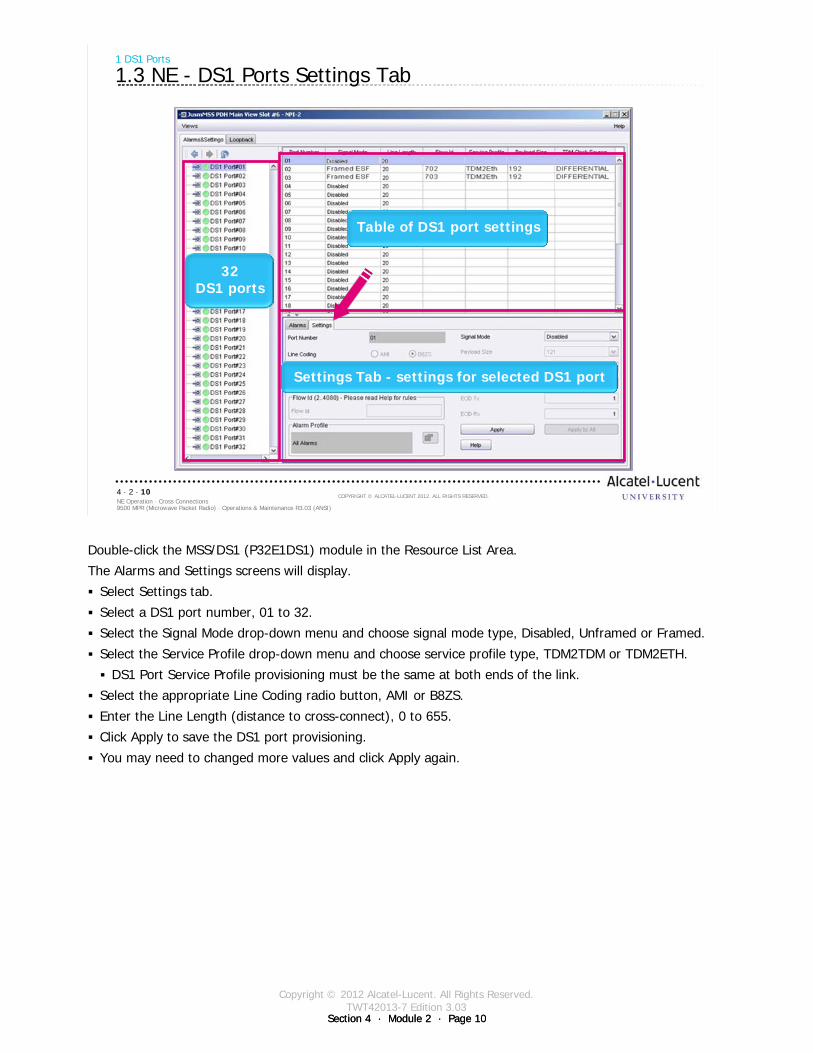
Copyright © 2012 Alcatel-Lucent. All Rights Reserved.TWT42013-7 Edition 3.03
Section 4 · Module 2 · Page 10Section 4 · Module 2 · Page 10
9500 MPR (Microwave Packet Radio) · Operations & Maintenance R3.03 (ANSI)NE Operation · Cross Connections4 · 2 · 10
COPYRIGHT © ALCATEL-LUCENT 2012. ALL RIGHTS RESERVED.
1 DS1 Ports
1.3 NE - DS1 Ports Settings Tab
32DS1 ports
Table of DS1 port settings
Settings Tab - settings for selected DS1 port
Double-click the MSS/DS1 (P32E1DS1) module in the Resource List Area.
The Alarms and Settings screens will display.
Select Settings tab.
Select a DS1 port number, 01 to 32.
Select the Signal Mode drop-down menu and choose signal mode type, Disabled, Unframed or Framed.
Select the Service Profile drop-down menu and choose service profile type, TDM2TDM or TDM2ETH.
DS1 Port Service Profile provisioning must be the same at both ends of the link.
Select the appropriate Line Coding radio button, AMI or B8ZS.
Enter the Line Length (distance to cross-connect), 0 to 655.
Click Apply to save the DS1 port provisioning.
You may need to changed more values and click Apply again.
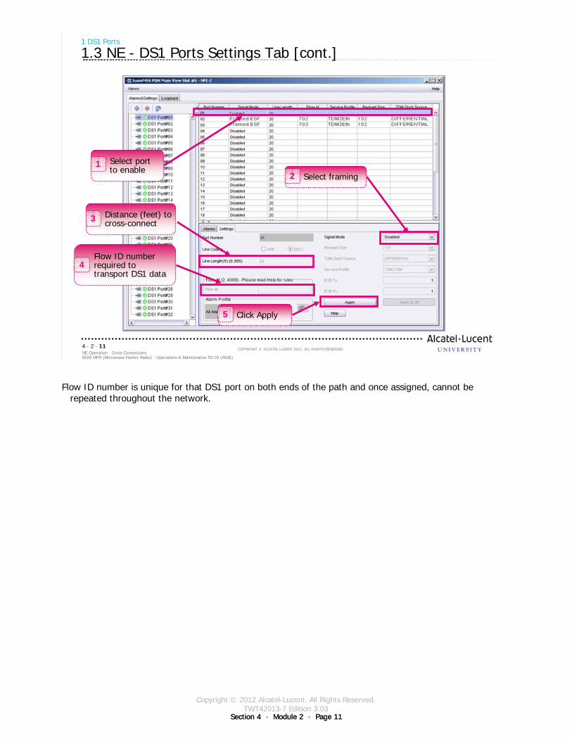
Copyright © 2012 Alcatel-Lucent. All Rights Reserved.TWT42013-7 Edition 3.03
Section 4 · Module 2 · Page 11Section 4 · Module 2 · Page 11
9500 MPR (Microwave Packet Radio) · Operations & Maintenance R3.03 (ANSI)NE Operation · Cross Connections4 · 2 · 11
COPYRIGHT © ALCATEL-LUCENT 2012. ALL RIGHTS RESERVED.
1 DS1 Ports
1.3 NE - DS1 Ports Settings Tab [cont.]
Select port to enable
1Select framing2
Distance (feet) to cross-connect3
Flow ID number required to transport DS1 data
4
Click Apply5
Flow ID number is unique for that DS1 port on both ends of the path and once assigned, cannot be repeated throughout the network.
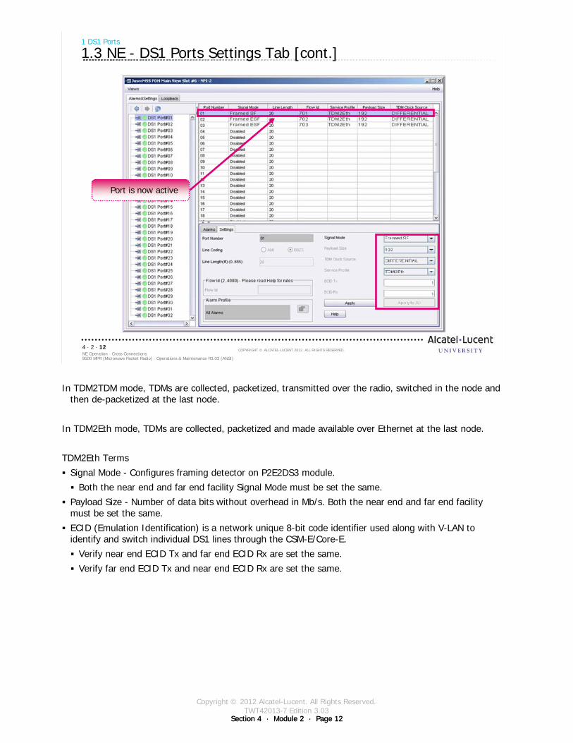
Copyright © 2012 Alcatel-Lucent. All Rights Reserved.TWT42013-7 Edition 3.03
Section 4 · Module 2 · Page 12Section 4 · Module 2 · Page 12
9500 MPR (Microwave Packet Radio) · Operations & Maintenance R3.03 (ANSI)NE Operation · Cross Connections4 · 2 · 12
COPYRIGHT © ALCATEL-LUCENT 2012. ALL RIGHTS RESERVED.
1 DS1 Ports
1.3 NE - DS1 Ports Settings Tab [cont.]
Port is now active
In TDM2TDM mode, TDMs are collected, packetized, transmitted over the radio, switched in the node and then de-packetized at the last node.
In TDM2Eth mode, TDMs are collected, packetized and made available over Ethernet at the last node.
TDM2Eth Terms
Signal Mode - Configures framing detector on P2E2DS3 module.
Both the near end and far end facility Signal Mode must be set the same.
Payload Size - Number of data bits without overhead in Mb/s. Both the near end and far end facility must be set the same.
ECID (Emulation Identification) is a network unique 8-bit code identifier used along with V-LAN to identify and switch individual DS1 lines through the CSM-E/Core-E.
Verify near end ECID Tx and far end ECID Rx are set the same.
Verify far end ECID Tx and near end ECID Rx are set the same.

Copyright © 2012 Alcatel-Lucent. All Rights Reserved.TWT42013-7 Edition 3.03
Section 4 · Module 2 · Page 13Section 4 · Module 2 · Page 13
9500 MPR (Microwave Packet Radio) · Operations & Maintenance R3.03 (ANSI)NE Operation · Cross Connections4 · 2 · 13
COPYRIGHT © ALCATEL-LUCENT 2012. ALL RIGHTS RESERVED.
Exercise
Time allowed:
Lab Exercise 6Configure DS1 Ports

Copyright © 2012 Alcatel-Lucent. All Rights Reserved.TWT42013-7 Edition 3.03
Section 4 · Module 2 · Page 14Section 4 · Module 2 · Page 14
9500 MPR (Microwave Packet Radio) · Operations & Maintenance R3.03 (ANSI)NE Operation · Cross Connections4 · 2 · 14
COPYRIGHT © ALCATEL-LUCENT 2012. ALL RIGHTS RESERVED.
Blank page
Switch to notes view!
This page intentionally left blank

Copyright © 2012 Alcatel-Lucent. All Rights Reserved.TWT42013-7 Edition 3.03
Section 4 · Module 2 · Page 15
9500 MPR (Microwave Packet Radio) · Operations & Maintenance R3.03 (ANSI)NE Operation · Cross Connections4 · 2 · 15
COPYRIGHT © ALCATEL-LUCENT 2012. ALL RIGHTS RESERVED.
2 Cross-Connections
Copyright © 2012 Alcatel-Lucent. All Rights Reserved.TWT42013-7 Edition 3.03
Section 4 · Module 2 · Page 16Section 4 · Module 2 · Page 16
9500 MPR (Microwave Packet Radio) · Operations & Maintenance R3.03 (ANSI)NE Operation · Cross Connections4 · 2 · 16
COPYRIGHT © ALCATEL-LUCENT 2012. ALL RIGHTS RESERVED.
2 Cross-Connections
2.1 Cross-Connections
Cross connection is only required for TDM traffic. Generic Ethernet traffic is handled automatically via MAC Address learning in the Ethernet switch. Cross connections can also be used with point-to-point VLAN Ethernet traffic to direct traffic based on a VLAN tag rather than MAC address
The cross connections screen is used to configure switching of packetized data. Using this screen, the operator can switch:
PDH to Radio:PDH (DS1 port) to RADIO (MOD300 or EAS/P8ETH radio port)PDH (DS3 port) to RADIO (MOD300 or EAS/P8ETH radio port)
PDH to Ethernet:PDH (DS1 port) to ETH (CSM-E/Core-E or EAS/P8ETH Ethernet port)PDH (DS3 port) to ETH (CSM-E/Core-E or EAS/P8ETH Ethernet port)
Ethernet to Radio:ETH (CSM-E/Core-E Ethernet port) to RADIO (MOD300 or EAS/P8ETH radio port)ETH (EAS/P8ETH Ethernet port) to RADIO (MOD300 or EAS/P8ETH radio port)
Radio to Radio:RADIO (MOD300 radio port) to RADIO (MOD300 radio port)RADIO (EAS/P8ETH radio port) to RADIO (MOD300 or EAS/P8ETH radio port)
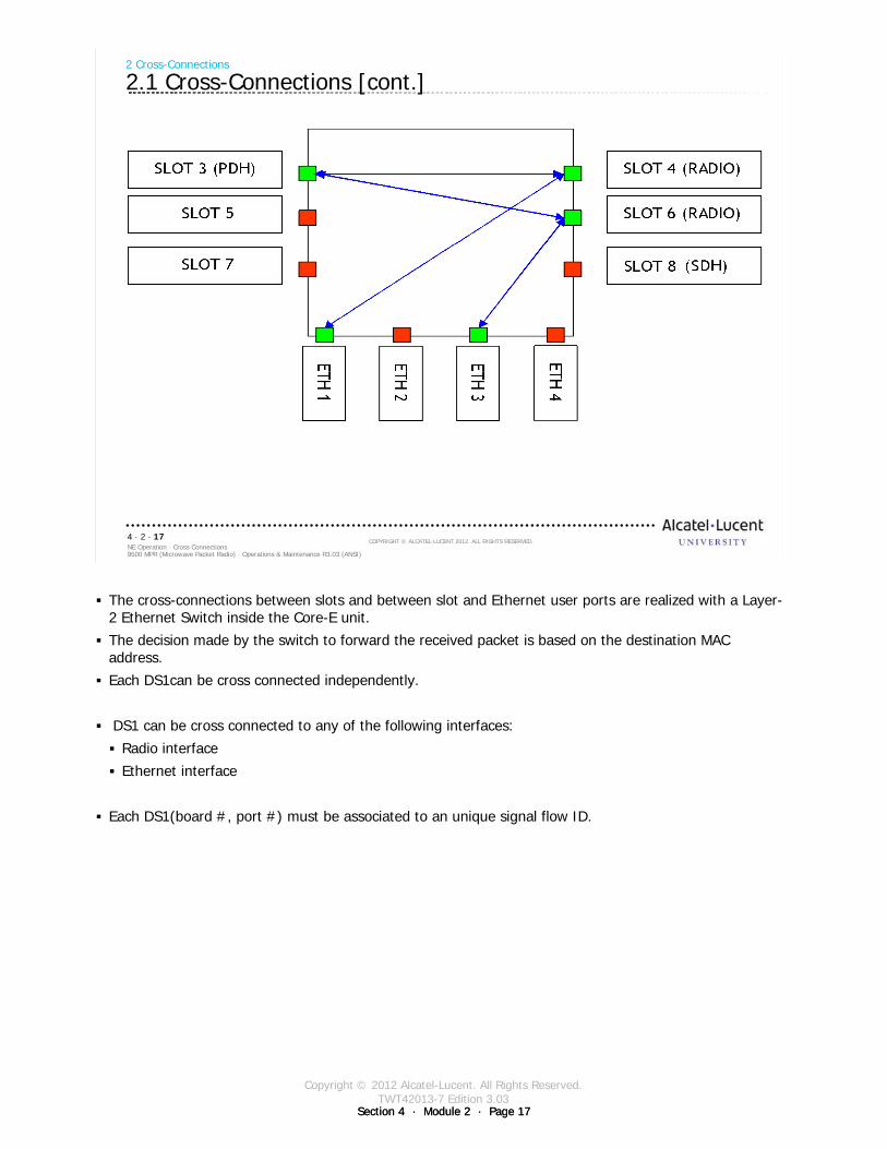
Copyright © 2012 Alcatel-Lucent. All Rights Reserved.TWT42013-7 Edition 3.03
Section 4 · Module 2 · Page 17Section 4 · Module 2 · Page 17
9500 MPR (Microwave Packet Radio) · Operations & Maintenance R3.03 (ANSI)NE Operation · Cross Connections4 · 2 · 17
COPYRIGHT © ALCATEL-LUCENT 2012. ALL RIGHTS RESERVED.
2 Cross-Connections
2.1 Cross-Connections [cont.]
The cross-connections between slots and between slot and Ethernet user ports are realized with a Layer-2 Ethernet Switch inside the Core-E unit.
The decision made by the switch to forward the received packet is based on the destination MAC address.
Each DS1can be cross connected independently.
DS1 can be cross connected to any of the following interfaces:
Radio interface
Ethernet interface
Each DS1(board #, port #) must be associated to an unique signal flow ID.
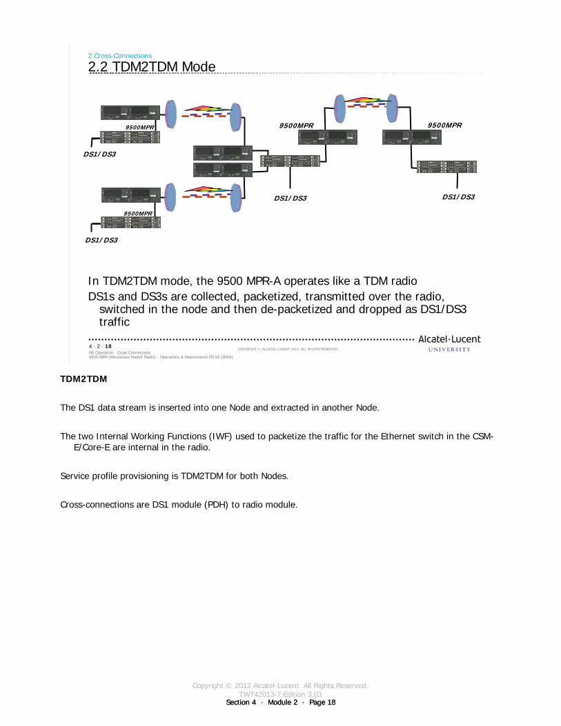
Copyright © 2012 Alcatel-Lucent. All Rights Reserved.TWT42013-7 Edition 3.03
Section 4 · Module 2 · Page 18Section 4 · Module 2 · Page 18
9500 MPR (Microwave Packet Radio) · Operations & Maintenance R3.03 (ANSI)NE Operation · Cross Connections4 · 2 · 18
COPYRIGHT © ALCATEL-LUCENT 2012. ALL RIGHTS RESERVED.
2 Cross-Connections
2.2 TDM2TDM Mode
In TDM2TDM mode, the 9500 MPR-A operates like a TDM radioDS1s and DS3s are collected, packetized, transmitted over the radio,
switched in the node and then de-packetized and dropped as DS1/DS3 traffic
9500MPR9500MPR
9500MPR
9500MPR
DS1/DS3
DS1/DS3
DS1/DS3 DS1/DS3
TDM2TDM
The DS1 data stream is inserted into one Node and extracted in another Node.
The two Internal Working Functions (IWF) used to packetize the traffic for the Ethernet switch in the CSM-E/Core-E are internal in the radio.
Service profile provisioning is TDM2TDM for both Nodes.
Cross-connections are DS1 module (PDH) to radio module.
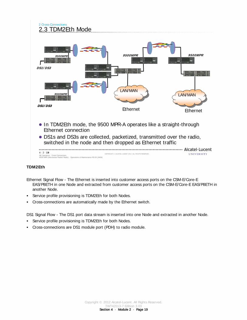
Copyright © 2012 Alcatel-Lucent. All Rights Reserved.TWT42013-7 Edition 3.03
Section 4 · Module 2 · Page 19Section 4 · Module 2 · Page 19
9500 MPR (Microwave Packet Radio) · Operations & Maintenance R3.03 (ANSI)NE Operation · Cross Connections4 · 2 · 19
COPYRIGHT © ALCATEL-LUCENT 2012. ALL RIGHTS RESERVED.
DS1/DS3
DS1/DS3
2 Cross-Connections
2.3 TDM2Eth Mode
Ethernet Ethernet
LAN/MANLAN/MANLAN/MANLAN/MAN
9500MPR9500MPR 9500MPR
In TDM2Eth mode, the 9500 MPR-A operates like a straight-through Ethernet connectionDS1s and DS3s are collected, packetized, transmitted over the radio, switched in the node and then dropped as Ethernet traffic
DS1/DS3
9500MPR
TDM2Eth
Ethernet Signal Flow - The Ethernet is inserted into customer access ports on the CSM-E/Core-E EAS/P8ETH in one Node and extracted from customer access ports on the CSM-E/Core-E EAS/P8ETH in another Node.
Service profile provisioning is TDM2Eth for both Nodes.
Cross-connections are automatically made by the Ethernet switch.
DS1 Signal Flow - The DS1 port data stream is inserted into one Node and extracted in another Node.
Service profile provisioning is TDM2Eth for both Nodes.
Cross-connections are DS1 module port (PDH) to radio module.
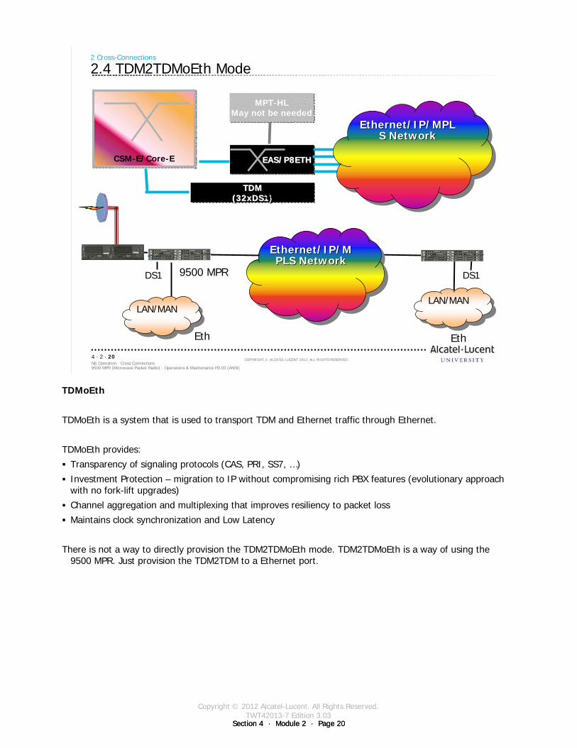
Copyright © 2012 Alcatel-Lucent. All Rights Reserved.TWT42013-7 Edition 3.03
Section 4 · Module 2 · Page 20Section 4 · Module 2 · Page 20
9500 MPR (Microwave Packet Radio) · Operations & Maintenance R3.03 (ANSI)NE Operation · Cross Connections4 · 2 · 20
COPYRIGHT © ALCATEL-LUCENT 2012. ALL RIGHTS RESERVED.
2 Cross-Connections
2.4 TDM2TDMoEth Mode
CSM-E/Core-ECSM-E/Core-E
TDM(32xDS1)
TDMTDM(32xDS1(32xDS1)
MPT-HLMay not be needed
MPT-HLMay not be needed
EAS/P8ETHEAS/P8ETHEAS/P8ETH n x Ethernet
Ethernet/IP/MPLS Network
Ethernet/IP/MEthernet/IP/MPLS NetworkPLS Network
Eth
9500 MPR
9500 MPR
Eth
LAN/MANLAN/MANLAN/MANLAN/MAN
Ethernet/IP/MPLS Network
Ethernet/IP/MPLEthernet/IP/MPLS NetworkS Network
DS1 DS1
TDMoEth
TDMoEth is a system that is used to transport TDM and Ethernet traffic through Ethernet.
TDMoEth provides:
Transparency of signaling protocols (CAS, PRI, SS7, …)
Investment Protection – migration to IP without compromising rich PBX features (evolutionary approach with no fork-lift upgrades)
Channel aggregation and multiplexing that improves resiliency to packet loss
Maintains clock synchronization and Low Latency
There is not a way to directly provision the TDM2TDMoEth mode. TDM2TDMoEth is a way of using the 9500 MPR. Just provision the TDM2TDM to a Ethernet port.
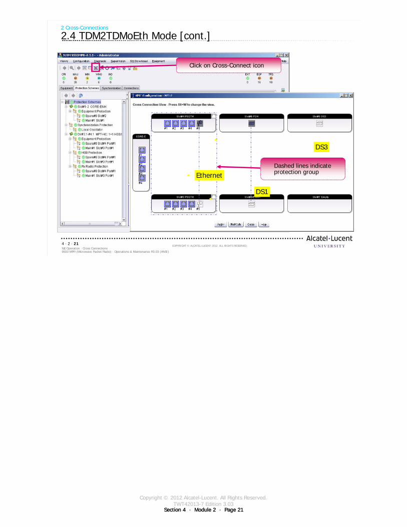
Copyright © 2012 Alcatel-Lucent. All Rights Reserved.TWT42013-7 Edition 3.03
Section 4 · Module 2 · Page 21Section 4 · Module 2 · Page 21
9500 MPR (Microwave Packet Radio) · Operations & Maintenance R3.03 (ANSI)NE Operation · Cross Connections4 · 2 · 21
COPYRIGHT © ALCATEL-LUCENT 2012. ALL RIGHTS RESERVED.
2 Cross-Connections
2.4 TDM2TDMoEth Mode [cont.]
DS1
Ethernet
DS3
Dashed lines indicate protection group
Click on Cross-Connect icon
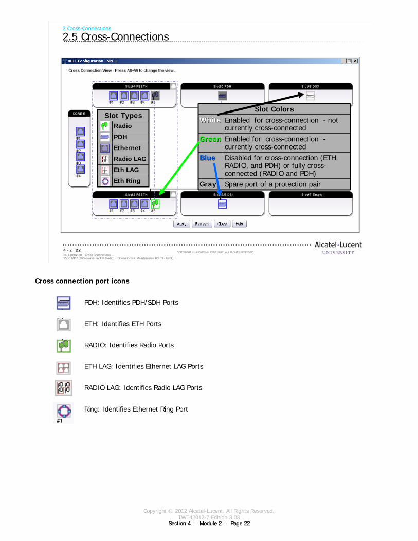
Copyright © 2012 Alcatel-Lucent. All Rights Reserved.TWT42013-7 Edition 3.03
Section 4 · Module 2 · Page 22Section 4 · Module 2 · Page 22
9500 MPR (Microwave Packet Radio) · Operations & Maintenance R3.03 (ANSI)NE Operation · Cross Connections4 · 2 · 22
COPYRIGHT © ALCATEL-LUCENT 2012. ALL RIGHTS RESERVED.
2 Cross-Connections
2.5 Cross-Connections
Slot ColorsWhiteWhite Enabled for cross-connection - not
currently cross-connected
GreenGreen Enabled for cross-connection -currently cross-connected
BlueBlue Disabled for cross-connection (ETH, RADIO, and PDH) or fully cross-connected (RADIO and PDH)
GrayGray Spare port of a protection pair
Slot TypesRadio
PDH
Ethernet
Radio LAG
Eth LAG
Eth Ring
Cross connection port icons
PDH: Identifies PDH/SDH Ports
ETH: Identifies ETH Ports
RADIO: Identifies Radio Ports
ETH LAG: Identifies Ethernet LAG Ports
RADIO LAG: Identifies Radio LAG Ports
Ring: Identifies Ethernet Ring Port
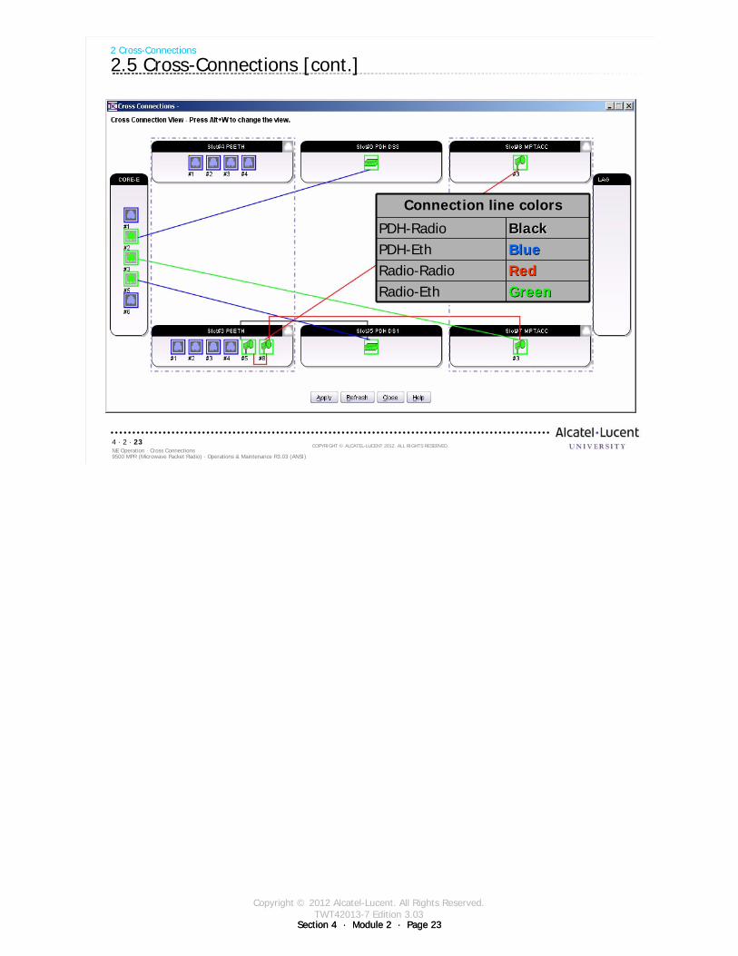
Copyright © 2012 Alcatel-Lucent. All Rights Reserved.TWT42013-7 Edition 3.03
Section 4 · Module 2 · Page 23Section 4 · Module 2 · Page 23
9500 MPR (Microwave Packet Radio) · Operations & Maintenance R3.03 (ANSI)NE Operation · Cross Connections4 · 2 · 23
COPYRIGHT © ALCATEL-LUCENT 2012. ALL RIGHTS RESERVED.
2 Cross-Connections
2.5 Cross-Connections [cont.]
Connection line colors
PDH-Radio BlackBlackPDH-Eth BlueBlueRadio-Radio RedRedRadio-Eth GreenGreen

Copyright © 2012 Alcatel-Lucent. All Rights Reserved.TWT42013-7 Edition 3.03
Section 4 · Module 2 · Page 24Section 4 · Module 2 · Page 24Section 4 · Module 2 · Page 24
9500 MPR (Microwave Packet Radio) · Operations & Maintenance R3.03 (ANSI)NE Operation · Cross Connections4 · 2 · 24
COPYRIGHT © ALCATEL-LUCENT 2012. ALL RIGHTS RESERVED.
Blank page
Switch to notes view!
This page intentionally left blank

Copyright © 2012 Alcatel-Lucent. All Rights Reserved.TWT42013-7 Edition 3.03
Section 4 · Module 2 · Page 25
9500 MPR (Microwave Packet Radio) · Operations & Maintenance R3.03 (ANSI)NE Operation · Cross Connections4 · 2 · 25
COPYRIGHT © ALCATEL-LUCENT 2012. ALL RIGHTS RESERVED.
3 DS1 Cross-Connections
Refer to 9500 MPR Operation and Administration, 3EM23954AHAA, DLP-112 for more details
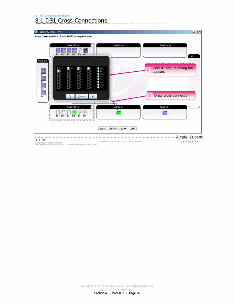
Copyright © 2012 Alcatel-Lucent. All Rights Reserved.TWT42013-7 Edition 3.03
Section 4 · Module 2 · Page 26Section 4 · Module 2 · Page 26
9500 MPR (Microwave Packet Radio) · Operations & Maintenance R3.03 (ANSI)NE Operation · Cross Connections4 · 2 · 26
COPYRIGHT © ALCATEL-LUCENT 2012. ALL RIGHTS RESERVED.
3 DS1 Cross-Connections
3.1 DS1 Cross-Connections
Flow ID pop-up dialog box appears2
Draw cross-connection1
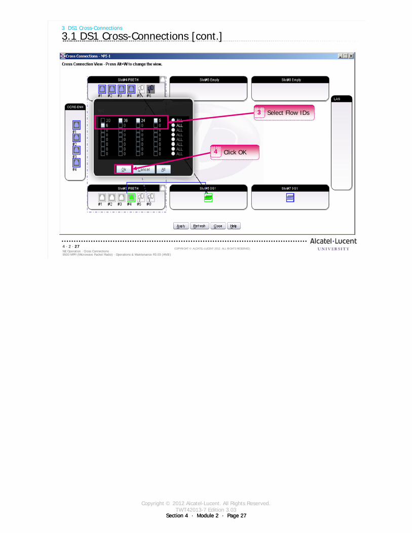
Copyright © 2012 Alcatel-Lucent. All Rights Reserved.TWT42013-7 Edition 3.03
Section 4 · Module 2 · Page 27Section 4 · Module 2 · Page 27
9500 MPR (Microwave Packet Radio) · Operations & Maintenance R3.03 (ANSI)NE Operation · Cross Connections4 · 2 · 27
COPYRIGHT © ALCATEL-LUCENT 2012. ALL RIGHTS RESERVED.
3 DS1 Cross-Connections
3.1 DS1 Cross-Connections [cont.]
Select Flow IDs3
Click OK4
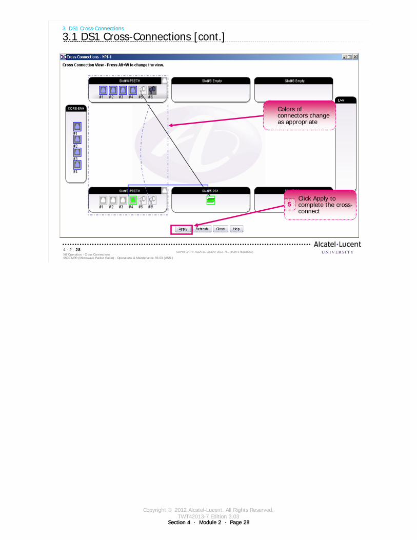
Copyright © 2012 Alcatel-Lucent. All Rights Reserved.TWT42013-7 Edition 3.03
Section 4 · Module 2 · Page 28Section 4 · Module 2 · Page 28
9500 MPR (Microwave Packet Radio) · Operations & Maintenance R3.03 (ANSI)NE Operation · Cross Connections4 · 2 · 28
COPYRIGHT © ALCATEL-LUCENT 2012. ALL RIGHTS RESERVED.
3 DS1 Cross-Connections
3.1 DS1 Cross-Connections [cont.]
Click Apply to complete the cross-connect
5
Colors of connectors change as appropriate
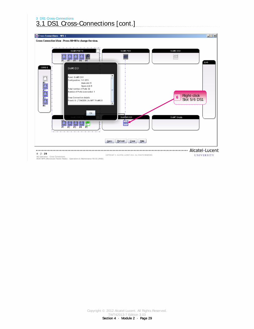
Copyright © 2012 Alcatel-Lucent. All Rights Reserved.TWT42013-7 Edition 3.03
Section 4 · Module 2 · Page 29Section 4 · Module 2 · Page 29
9500 MPR (Microwave Packet Radio) · Operations & Maintenance R3.03 (ANSI)NE Operation · Cross Connections4 · 2 · 29
COPYRIGHT © ALCATEL-LUCENT 2012. ALL RIGHTS RESERVED.
3 DS1 Cross-Connections
3.1 DS1 Cross-Connections [cont.]
Right-click Slot 5/6 DS16
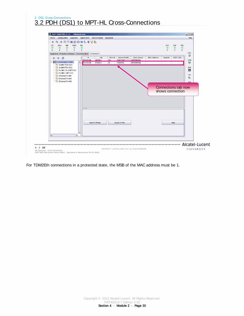
Copyright © 2012 Alcatel-Lucent. All Rights Reserved.TWT42013-7 Edition 3.03
Section 4 · Module 2 · Page 30Section 4 · Module 2 · Page 30
9500 MPR (Microwave Packet Radio) · Operations & Maintenance R3.03 (ANSI)NE Operation · Cross Connections4 · 2 · 30
COPYRIGHT © ALCATEL-LUCENT 2012. ALL RIGHTS RESERVED.
3 DS1 Cross-Connections
3.2 PDH (DS1) to MPT-HL Cross-Connections
Connections tab now shows connection
For TDM2Eth connections in a protected state, the MSB of the MAC address must be 1.

Copyright © 2012 Alcatel-Lucent. All Rights Reserved.TWT42013-7 Edition 3.03
Section 4 · Module 2 · Page 31Section 4 · Module 2 · Page 31
9500 MPR (Microwave Packet Radio) · Operations & Maintenance R3.03 (ANSI)NE Operation · Cross Connections4 · 2 · 31
COPYRIGHT © ALCATEL-LUCENT 2012. ALL RIGHTS RESERVED.
Exercise
Time allowed:
Lab Exercise 7DS1 Cross-Connections

Copyright © 2012 Alcatel-Lucent. All Rights Reserved.TWT42013-7 Edition 3.03
Section 4 · Module 2 · Page 32Section 4 · Module 2 · Page 32
9500 MPR (Microwave Packet Radio) · Operations & Maintenance R3.03 (ANSI)NE Operation · Cross Connections4 · 2 · 32
COPYRIGHT © ALCATEL-LUCENT 2012. ALL RIGHTS RESERVED.
Blank page
Switch to notes view!
This page intentionally left blank

Copyright © 2012 Alcatel-Lucent. All Rights Reserved.TWT42013-7 Edition 3.03
Section 4 · Module 2 · Page 33
9500 MPR (Microwave Packet Radio) · Operations & Maintenance R3.03 (ANSI)NE Operation · Cross Connections4 · 2 · 33
COPYRIGHT © ALCATEL-LUCENT 2012. ALL RIGHTS RESERVED.
4 DS3 Ports
Refer to 9500 MPR Operation and Administration, 3EM23954AHAA, DLP-104 and DLP-106 for more
details

Copyright © 2012 Alcatel-Lucent. All Rights Reserved.TWT42013-7 Edition 3.03
Section 4 · Module 2 · Page 34Section 4 · Module 2 · Page 34
9500 MPR (Microwave Packet Radio) · Operations & Maintenance R3.03 (ANSI)NE Operation · Cross Connections4 · 2 · 34
COPYRIGHT © ALCATEL-LUCENT 2012. ALL RIGHTS RESERVED.
4 DS3 Ports
4.1 NE Main View - Connections Tab without Connections
Connections Panel will be empty until cross-connects are configured
Cross-connections are always required for TDM traffic.
Generic Ethernet traffic is handled automatically via MAC Address learning in the Ethernet switch.
Cross-connections can also be used with point-to-point VLAN Ethernet traffic to direct traffic based on VLAN tag rather than MAC address.
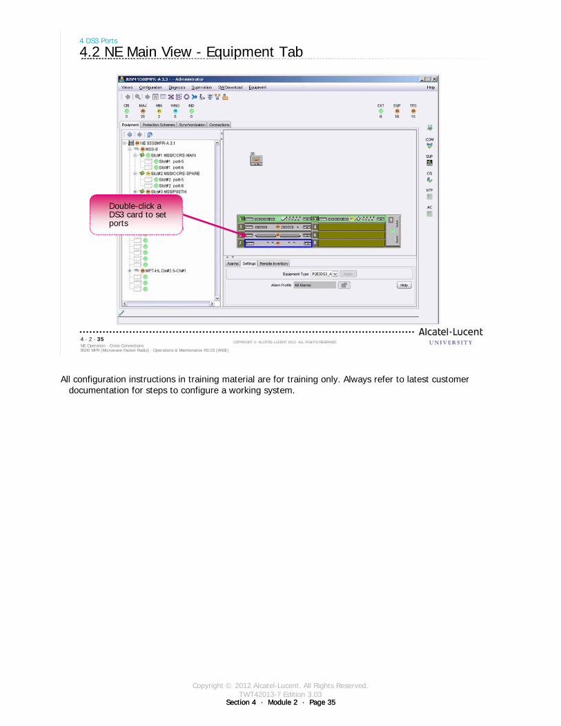
Copyright © 2012 Alcatel-Lucent. All Rights Reserved.TWT42013-7 Edition 3.03
Section 4 · Module 2 · Page 35Section 4 · Module 2 · Page 35
9500 MPR (Microwave Packet Radio) · Operations & Maintenance R3.03 (ANSI)NE Operation · Cross Connections4 · 2 · 35
COPYRIGHT © ALCATEL-LUCENT 2012. ALL RIGHTS RESERVED.
4 DS3 Ports
4.2 NE Main View - Equipment Tab
Double-click a DS3 card to set ports
All configuration instructions in training material are for training only. Always refer to latest customer documentation for steps to configure a working system.
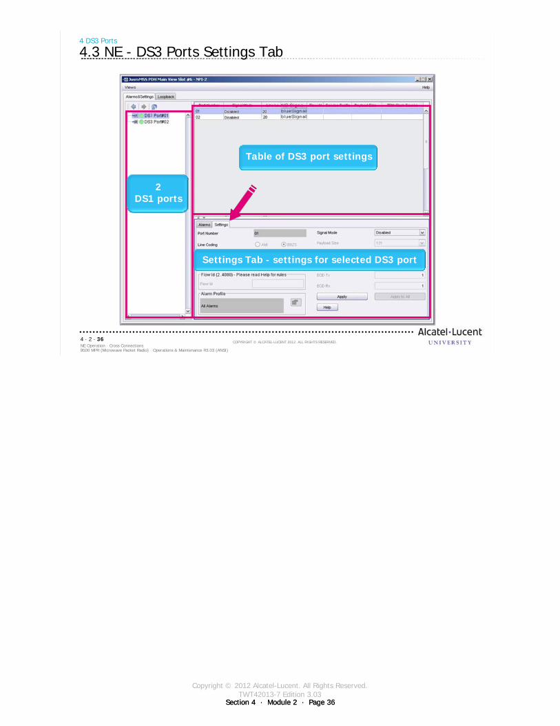
Copyright © 2012 Alcatel-Lucent. All Rights Reserved.TWT42013-7 Edition 3.03
Section 4 · Module 2 · Page 36Section 4 · Module 2 · Page 36
9500 MPR (Microwave Packet Radio) · Operations & Maintenance R3.03 (ANSI)NE Operation · Cross Connections4 · 2 · 36
COPYRIGHT © ALCATEL-LUCENT 2012. ALL RIGHTS RESERVED.
4 DS3 Ports
4.3 NE - DS3 Ports Settings Tab
2DS1 ports
Table of DS3 port settings
Settings Tab - settings for selected DS3 port
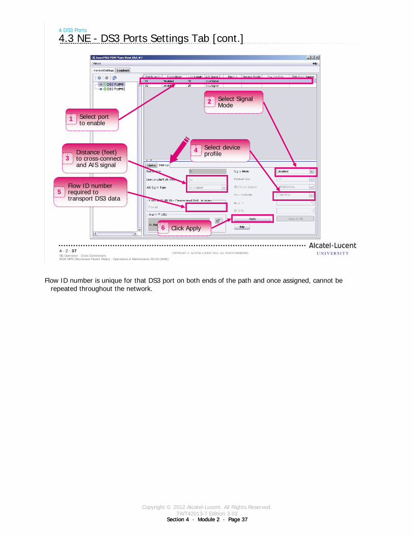
Copyright © 2012 Alcatel-Lucent. All Rights Reserved.TWT42013-7 Edition 3.03
Section 4 · Module 2 · Page 37Section 4 · Module 2 · Page 37
9500 MPR (Microwave Packet Radio) · Operations & Maintenance R3.03 (ANSI)NE Operation · Cross Connections4 · 2 · 37
COPYRIGHT © ALCATEL-LUCENT 2012. ALL RIGHTS RESERVED.
4 DS3 Ports
4.3 NE - DS3 Ports Settings Tab [cont.]
Select port to enable
1
Click Apply6
Distance (feet) to cross-connect and AIS signal
3
Select Signal Mode2
Select device profile4
Flow ID number required to transport DS3 data
5
Flow ID number is unique for that DS3 port on both ends of the path and once assigned, cannot be repeated throughout the network.
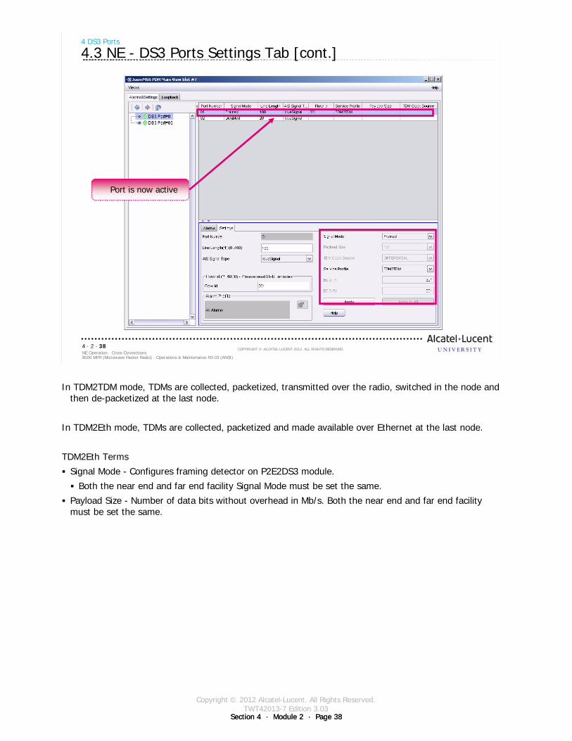
Copyright © 2012 Alcatel-Lucent. All Rights Reserved.TWT42013-7 Edition 3.03
Section 4 · Module 2 · Page 38Section 4 · Module 2 · Page 38
9500 MPR (Microwave Packet Radio) · Operations & Maintenance R3.03 (ANSI)NE Operation · Cross Connections4 · 2 · 38
COPYRIGHT © ALCATEL-LUCENT 2012. ALL RIGHTS RESERVED.
4 DS3 Ports
4.3 NE - DS3 Ports Settings Tab [cont.]
Port is now active
In TDM2TDM mode, TDMs are collected, packetized, transmitted over the radio, switched in the node and then de-packetized at the last node.
In TDM2Eth mode, TDMs are collected, packetized and made available over Ethernet at the last node.
TDM2Eth Terms
Signal Mode - Configures framing detector on P2E2DS3 module.
Both the near end and far end facility Signal Mode must be set the same.
Payload Size - Number of data bits without overhead in Mb/s. Both the near end and far end facility must be set the same.

Copyright © 2012 Alcatel-Lucent. All Rights Reserved.TWT42013-7 Edition 3.03
Section 4 · Module 2 · Page 39Section 4 · Module 2 · Page 39
9500 MPR (Microwave Packet Radio) · Operations & Maintenance R3.03 (ANSI)NE Operation · Cross Connections4 · 2 · 39
COPYRIGHT © ALCATEL-LUCENT 2012. ALL RIGHTS RESERVED.
Exercise
Time allowed:
Lab Exercise 8Configure DS3 Ports

Copyright © 2012 Alcatel-Lucent. All Rights Reserved.TWT42013-7 Edition 3.03
Section 4 · Module 2 · Page 40Section 4 · Module 2 · Page 40
9500 MPR (Microwave Packet Radio) · Operations & Maintenance R3.03 (ANSI)NE Operation · Cross Connections4 · 2 · 40
COPYRIGHT © ALCATEL-LUCENT 2012. ALL RIGHTS RESERVED.
Blank page
Switch to notes view!
This page intentionally left blank

Copyright © 2012 Alcatel-Lucent. All Rights Reserved.TWT42013-7 Edition 3.03
Section 4 · Module 2 · Page 41
9500 MPR (Microwave Packet Radio) · Operations & Maintenance R3.03 (ANSI)NE Operation · Cross Connections4 · 2 · 41
COPYRIGHT © ALCATEL-LUCENT 2012. ALL RIGHTS RESERVED.
5 DS3 Cross-Connections
Refer to 9500 MPR Operations and Administration, 3EM23954AHAA, DLP-112 for more details
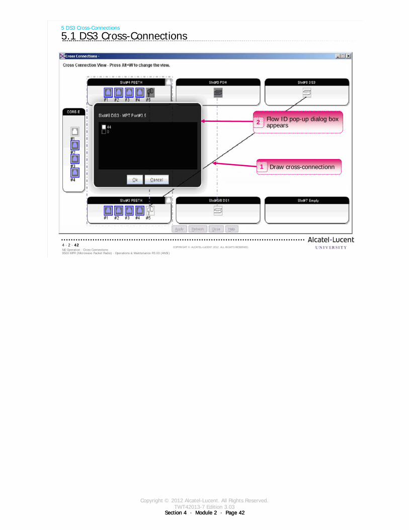
Copyright © 2012 Alcatel-Lucent. All Rights Reserved.TWT42013-7 Edition 3.03
Section 4 · Module 2 · Page 42Section 4 · Module 2 · Page 42
9500 MPR (Microwave Packet Radio) · Operations & Maintenance R3.03 (ANSI)NE Operation · Cross Connections4 · 2 · 42
COPYRIGHT © ALCATEL-LUCENT 2012. ALL RIGHTS RESERVED.
5 DS3 Cross-Connections
5.1 DS3 Cross-Connections
Flow ID pop-up dialog box appears2
Draw cross-connectionn1
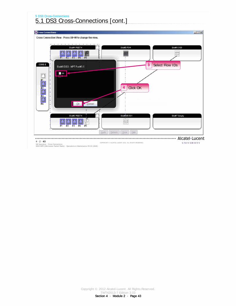
Copyright © 2012 Alcatel-Lucent. All Rights Reserved.TWT42013-7 Edition 3.03
Section 4 · Module 2 · Page 43Section 4 · Module 2 · Page 43
9500 MPR (Microwave Packet Radio) · Operations & Maintenance R3.03 (ANSI)NE Operation · Cross Connections4 · 2 · 43
COPYRIGHT © ALCATEL-LUCENT 2012. ALL RIGHTS RESERVED.
5 DS3 Cross-Connections
5.1 DS3 Cross-Connections [cont.]
Select Flow IDs3
Click OK4
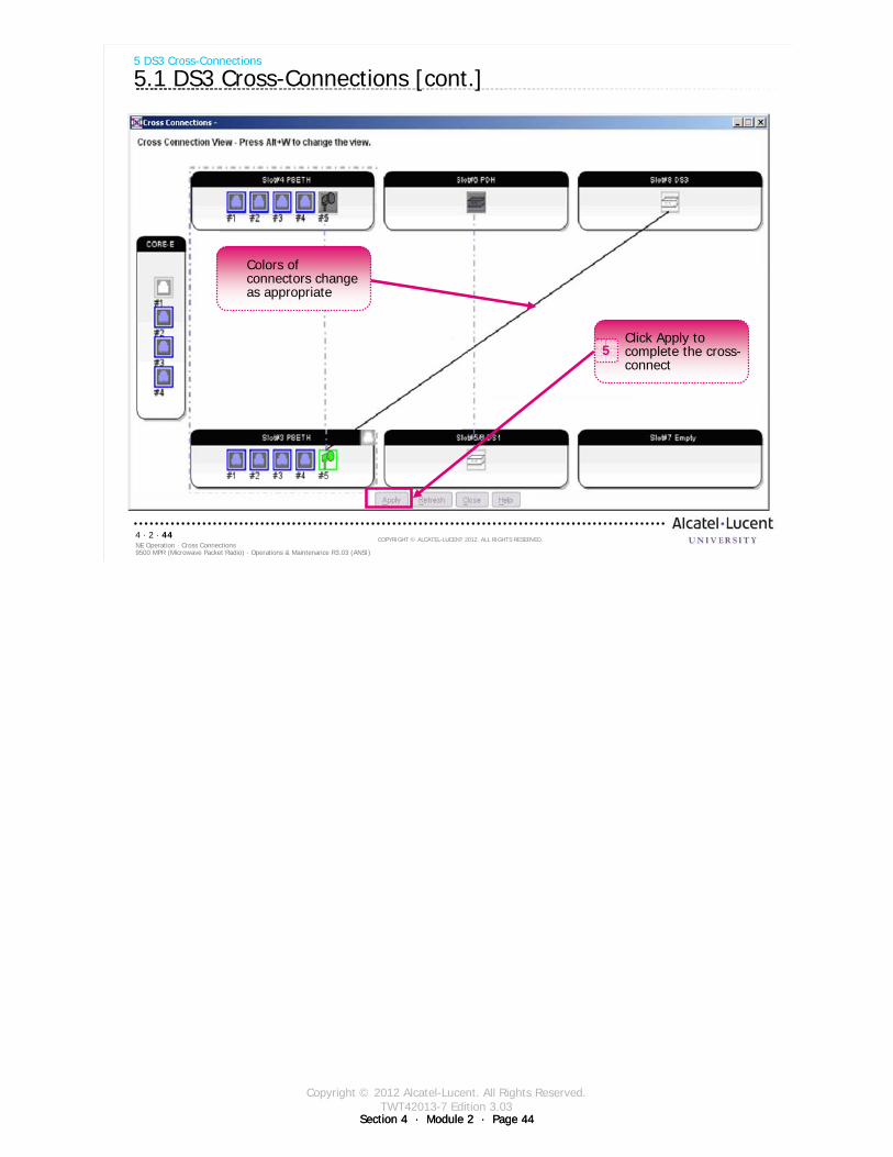
Copyright © 2012 Alcatel-Lucent. All Rights Reserved.TWT42013-7 Edition 3.03
Section 4 · Module 2 · Page 44Section 4 · Module 2 · Page 44
9500 MPR (Microwave Packet Radio) · Operations & Maintenance R3.03 (ANSI)NE Operation · Cross Connections4 · 2 · 44
COPYRIGHT © ALCATEL-LUCENT 2012. ALL RIGHTS RESERVED.
5 DS3 Cross-Connections
5.1 DS3 Cross-Connections [cont.]
Click Apply to complete the cross-connect
5
Colors of connectors change as appropriate
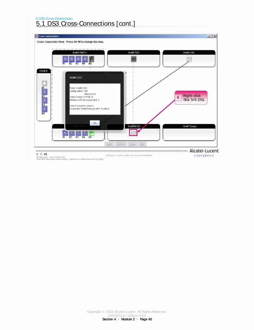
Copyright © 2012 Alcatel-Lucent. All Rights Reserved.TWT42013-7 Edition 3.03
Section 4 · Module 2 · Page 45Section 4 · Module 2 · Page 45
9500 MPR (Microwave Packet Radio) · Operations & Maintenance R3.03 (ANSI)NE Operation · Cross Connections4 · 2 · 45
COPYRIGHT © ALCATEL-LUCENT 2012. ALL RIGHTS RESERVED.
5 DS3 Cross-Connections
5.1 DS3 Cross-Connections [cont.]
Right-click Slot 5/6 DS16
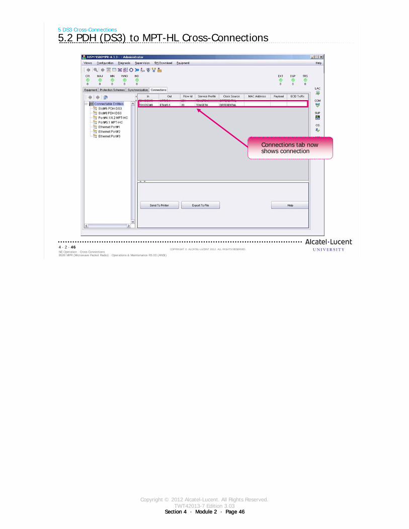
Copyright © 2012 Alcatel-Lucent. All Rights Reserved.TWT42013-7 Edition 3.03
Section 4 · Module 2 · Page 46Section 4 · Module 2 · Page 46
9500 MPR (Microwave Packet Radio) · Operations & Maintenance R3.03 (ANSI)NE Operation · Cross Connections4 · 2 · 46
COPYRIGHT © ALCATEL-LUCENT 2012. ALL RIGHTS RESERVED.
5 DS3 Cross-Connections
5.2 PDH (DS3) to MPT-HL Cross-Connections
Connections tab now shows connection

Copyright © 2012 Alcatel-Lucent. All Rights Reserved.TWT42013-7 Edition 3.03
Section 4 · Module 2 · Page 47Section 4 · Module 2 · Page 47
9500 MPR (Microwave Packet Radio) · Operations & Maintenance R3.03 (ANSI)NE Operation · Cross Connections4 · 2 · 47
COPYRIGHT © ALCATEL-LUCENT 2012. ALL RIGHTS RESERVED.
Exercise
Time allowed:
Lab Exercise 9DS3 Cross-Connections

Copyright © 2012 Alcatel-Lucent. All Rights Reserved.TWT42013-7 Edition 3.03
Section 4 · Module 2 · Page 48Section 4 · Module 2 · Page 48
9500 MPR (Microwave Packet Radio) · Operations & Maintenance R3.03 (ANSI)NE Operation · Cross Connections4 · 2 · 48
COPYRIGHT © ALCATEL-LUCENT 2012. ALL RIGHTS RESERVED.
Blank page
Switch to notes view!
This page intentionally left blank

Copyright © 2012 Alcatel-Lucent. All Rights Reserved.TWT42013-7 Edition 3.03
Section 4 · Module 2 · Page 49
9500 MPR (Microwave Packet Radio) · Operations & Maintenance R3.03 (ANSI)NE Operation · Cross Connections4 · 2 · 49
COPYRIGHT © ALCATEL-LUCENT 2012. ALL RIGHTS RESERVED.
6 Ethernet Ports
Refer to 9500 MPR Operations and Administration, 3EM23954AHAA, DLP-104 and DLP-108 for more
details
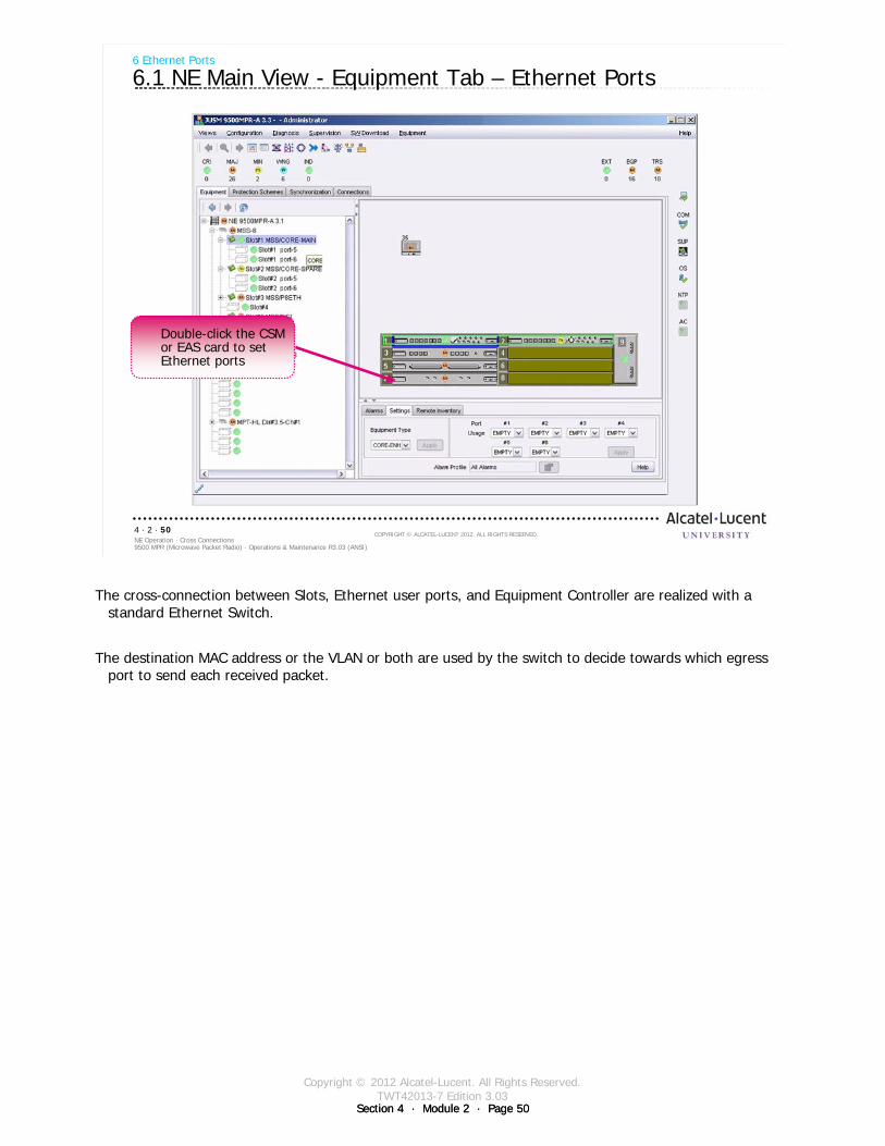
Copyright © 2012 Alcatel-Lucent. All Rights Reserved.TWT42013-7 Edition 3.03
Section 4 · Module 2 · Page 50Section 4 · Module 2 · Page 50
9500 MPR (Microwave Packet Radio) · Operations & Maintenance R3.03 (ANSI)NE Operation · Cross Connections4 · 2 · 50
COPYRIGHT © ALCATEL-LUCENT 2012. ALL RIGHTS RESERVED.
6 Ethernet Ports
6.1 NE Main View - Equipment Tab – Ethernet Ports
Double-click the CSM or EAS card to set Ethernet ports
The cross-connection between Slots, Ethernet user ports, and Equipment Controller are realized with a standard Ethernet Switch.
The destination MAC address or the VLAN or both are used by the switch to decide towards which egress port to send each received packet.
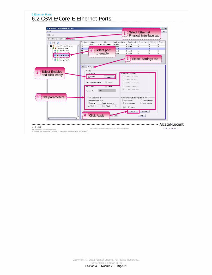
Copyright © 2012 Alcatel-Lucent. All Rights Reserved.TWT42013-7 Edition 3.03
Section 4 · Module 2 · Page 51Section 4 · Module 2 · Page 51
9500 MPR (Microwave Packet Radio) · Operations & Maintenance R3.03 (ANSI)NE Operation · Cross Connections4 · 2 · 51
COPYRIGHT © ALCATEL-LUCENT 2012. ALL RIGHTS RESERVED.
6 Ethernet Ports
6.2 CSM-E/Core-E Ethernet Ports
Select port to enable
2
Click Apply6
Select Settings tab3
Select Ethernet Physical Interface tab1
Select Enabled and click Apply4
Set parameters5

Copyright © 2012 Alcatel-Lucent. All Rights Reserved.TWT42013-7 Edition 3.03
Section 4 · Module 2 · Page 52Section 4 · Module 2 · Page 52
9500 MPR (Microwave Packet Radio) · Operations & Maintenance R3.03 (ANSI)NE Operation · Cross Connections4 · 2 · 52
COPYRIGHT © ALCATEL-LUCENT 2012. ALL RIGHTS RESERVED.
6 Ethernet Ports
6.3 EAS/P8ETH Ethernet Ports
Select port to enable
2
Click Apply6
Select Settings tab3
Select Ethernet Physical Interface tab1
Select Enabled and click Apply4
Set parameters5

Copyright © 2012 Alcatel-Lucent. All Rights Reserved.TWT42013-7 Edition 3.03
Section 4 · Module 2 · Page 53Section 4 · Module 2 · Page 53
9500 MPR (Microwave Packet Radio) · Operations & Maintenance R3.03 (ANSI)NE Operation · Cross Connections4 · 2 · 53
COPYRIGHT © ALCATEL-LUCENT 2012. ALL RIGHTS RESERVED.
6 Ethernet Ports
6.4 CSM-E/Core-E TMN Interface
Select port to enable
1
Select Settings tab2
Set parameters3
Click Apply4
Provision TMN Interface
The Telecommunications Management Network (TMN) is a protocol model defined by ITU-T for managing open systems, such as 9500 MPR, in a communications network.
1. Select TMN Interface tab.
2. Select TMN Port in left frame.
3. Select Settings tab.
4. Select TMN Ethernet Enabled check box.
5. Enter the IP Address and IP Mask.
6. Select the IP Routing Protocol drop-down menu and choose Static Routing.
or
Select the IP Routing Protocol drop-down menu and choose OSPF.
7. Click Apply to store TMN Interface provisioning.
Copyright © 2012 Alcatel-Lucent. All Rights Reserved.TWT42013-7 Edition 3.03
Section 4 · Module 2 · Page 54Section 4 · Module 2 · Page 54
9500 MPR (Microwave Packet Radio) · Operations & Maintenance R3.03 (ANSI)NE Operation · Cross Connections4 · 2 · 54
COPYRIGHT © ALCATEL-LUCENT 2012. ALL RIGHTS RESERVED.
6 Ethernet Ports
6.5 Inband TMN VLAN
Inband TMN VLAN port allows the user to manage an 9500 MPR-A NE using a general Ethernet port from a central location (NOC).
Inband TMN messages reach the 9500 MPR-A over general user electrical Ethernet port 3 and optical Ethernet port 5 on the CSM-E/Core-E card.
Either electrical Ethernet port 3 or optical Ethernet port 5 can be used simultaneously for both general Ethernet traffic and TMN traffic.
Inband TMN provisioning applies to both electrical Ethernet port 3 andoptical Ethernet port 5.
TMN Inband TMN VLAN port interface and Port#4 TMN Ethernet interface should not be connected to a network at the same time.
The Inband TMN Ethernet interface:requires its own IP address and sub-network maskuses the same MAC address as Port#4 TMN Ethernet interfacedoes not require Port#4 TMN Ethernet interface to be provisionedrequires a unique VLAN ID (2-4080)
An optional OSPF area can be assigned, and must be provisioned prior to provisioning the Inband TMN Ethernet interface. Supports IP static routing.
This is another method of monitoring alarms.
Copyright © 2012 Alcatel-Lucent. All Rights Reserved.TWT42013-7 Edition 3.03
Section 4 · Module 2 · Page 55Section 4 · Module 2 · Page 55
9500 MPR (Microwave Packet Radio) · Operations & Maintenance R3.03 (ANSI)NE Operation · Cross Connections4 · 2 · 55
COPYRIGHT © ALCATEL-LUCENT 2012. ALL RIGHTS RESERVED.
6 Ethernet Ports
6.6 Static Routing
Usually used at radio WAN border routers to specify a default gateway to:use for reaching external networks when the external network does not use a supported dynamic routing protocol.control the exchange of dynamic route information between the radio WAN and the external network.
Static routing only supports provisioning a single route to a given destination at any radio. Route metrics and redundant routes are not supported. This limits the useful WAN topologies to linear and tree configurations when using Static Routing.
Maximum of 25 static route entries per radio.To minimize the number of static route entries required, the radio network addressing plan should allow for maximum route aggregation.Static routes directed out the PPP interfaces use the interface name as the route destination; rf, rptr, or (front) ppp.
Copyright © 2012 Alcatel-Lucent. All Rights Reserved.TWT42013-7 Edition 3.03
Section 4 · Module 2 · Page 56Section 4 · Module 2 · Page 56
9500 MPR (Microwave Packet Radio) · Operations & Maintenance R3.03 (ANSI)NE Operation · Cross Connections4 · 2 · 56
COPYRIGHT © ALCATEL-LUCENT 2012. ALL RIGHTS RESERVED.
Exercise
Time allowed:
Lab Exercise 10Configure Ethernet Port

Copyright © 2012 Alcatel-Lucent. All Rights Reserved.TWT42013-7 Edition 3.03
Section 4 · Module 2 · Page 57
9500 MPR (Microwave Packet Radio) · Operations & Maintenance R3.03 (ANSI)NE Operation · Cross Connections4 · 2 · 57
COPYRIGHT © ALCATEL-LUCENT 2012. ALL RIGHTS RESERVED.
7 Port Segregation
Refer to 9500 MPR Operation and Administration, 3EM23954AHAA, DLP-111 for more details
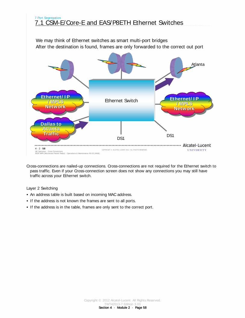
Copyright © 2012 Alcatel-Lucent. All Rights Reserved.TWT42013-7 Edition 3.03
Section 4 · Module 2 · Page 58Section 4 · Module 2 · Page 58
9500 MPR (Microwave Packet Radio) · Operations & Maintenance R3.03 (ANSI)NE Operation · Cross Connections4 · 2 · 58
COPYRIGHT © ALCATEL-LUCENT 2012. ALL RIGHTS RESERVED.
7 Port Segregation
7.1 CSM-E/Core-E and EAS/P8ETH Ethernet Switches
We may think of Ethernet switches as smart multi-port bridgesAfter the destination is found, frames are only forwarded to the correct out port
BAtlanta
DS1DS1
Ethernet Switch
B
Dallas to Atlanta Traffic
Dallas to Dallas to Atlanta Atlanta TrafficTraffic
Ethernet/IP/MPLS
Network
Ethernet/IPEthernet/IP/MPLS /MPLS
NetworkNetwork
Ethernet/IP/MPLS
Network
Ethernet/IPEthernet/IP/MPLS /MPLS
NetworkNetwork
Cross-connections are nailed-up connections. Cross-connections are not required for the Ethernet switch to pass traffic. Even if your Cross-connection screen does not show any connections you may still have traffic across your Ethernet switch.
Layer 2 Switching
An address table is built based on incoming MAC address.
If the address is not known the frames are sent to all ports.
If the address is in the table, frames are only sent to the correct port.
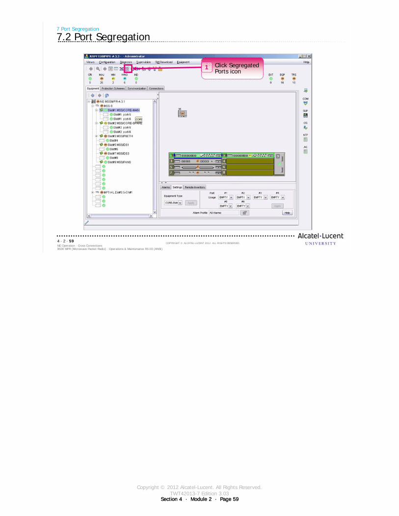
Copyright © 2012 Alcatel-Lucent. All Rights Reserved.TWT42013-7 Edition 3.03
Section 4 · Module 2 · Page 59Section 4 · Module 2 · Page 59
9500 MPR (Microwave Packet Radio) · Operations & Maintenance R3.03 (ANSI)NE Operation · Cross Connections4 · 2 · 59
COPYRIGHT © ALCATEL-LUCENT 2012. ALL RIGHTS RESERVED.
7 Port Segregation
7.2 Port Segregation
Click Segregated Ports icon
1
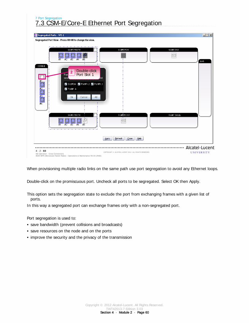
Copyright © 2012 Alcatel-Lucent. All Rights Reserved.TWT42013-7 Edition 3.03
Section 4 · Module 2 · Page 60Section 4 · Module 2 · Page 60
9500 MPR (Microwave Packet Radio) · Operations & Maintenance R3.03 (ANSI)NE Operation · Cross Connections4 · 2 · 60
COPYRIGHT © ALCATEL-LUCENT 2012. ALL RIGHTS RESERVED.
7 Port Segregation
7.3 CSM-E/Core-E Ethernet Port Segregation
Double-click Port Slot 1
2
When provisioning multiple radio links on the same path use port segregation to avoid any Ethernet loops.
Double-click on the promiscuous port. Uncheck all ports to be segregated. Select OK then Apply.
This option sets the segregation state to exclude the port from exchanging frames with a given list of ports.
In this way a segregated port can exchange frames only with a non-segregated port.
Port segregation is used to:
save bandwidth (prevent collisions and broadcasts)
save resources on the node and on the ports
improve the security and the privacy of the transmission
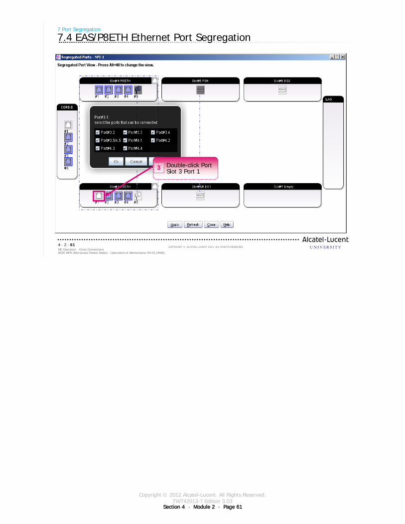
Copyright © 2012 Alcatel-Lucent. All Rights Reserved.TWT42013-7 Edition 3.03
Section 4 · Module 2 · Page 61Section 4 · Module 2 · Page 61
9500 MPR (Microwave Packet Radio) · Operations & Maintenance R3.03 (ANSI)NE Operation · Cross Connections4 · 2 · 61
COPYRIGHT © ALCATEL-LUCENT 2012. ALL RIGHTS RESERVED.
7 Port Segregation
7.4 EAS/P8ETH Ethernet Port Segregation
Double-click Port Slot 3 Port 1
3
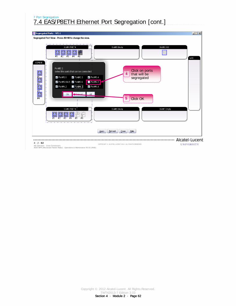
Copyright © 2012 Alcatel-Lucent. All Rights Reserved.TWT42013-7 Edition 3.03
Section 4 · Module 2 · Page 62Section 4 · Module 2 · Page 62
9500 MPR (Microwave Packet Radio) · Operations & Maintenance R3.03 (ANSI)NE Operation · Cross Connections4 · 2 · 62
COPYRIGHT © ALCATEL-LUCENT 2012. ALL RIGHTS RESERVED.
7 Port Segregation
7.4 EAS/P8ETH Ethernet Port Segregation [cont.]
Click on ports that will be segregated
4
Click OK5
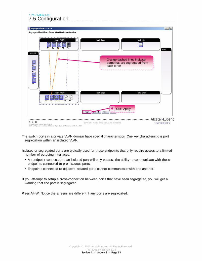
Copyright © 2012 Alcatel-Lucent. All Rights Reserved.TWT42013-7 Edition 3.03
Section 4 · Module 2 · Page 63Section 4 · Module 2 · Page 63
9500 MPR (Microwave Packet Radio) · Operations & Maintenance R3.03 (ANSI)NE Operation · Cross Connections4 · 2 · 63
COPYRIGHT © ALCATEL-LUCENT 2012. ALL RIGHTS RESERVED.
7 Port Segregation
7.5 Configuration
Orange dashed lines indicate ports that are segregated from each other
Click Apply6
The switch ports in a private VLAN domain have special characteristics. One key characteristic is port segregation within an isolated VLAN.
Isolated or segregated ports are typically used for those endpoints that only require access to a limited number of outgoing interfaces.
An endpoint connected to an isolated port will only possess the ability to communicate with those endpoints connected to promiscuous ports.
Endpoints connected to adjacent isolated ports cannot communicate with one another.
If you attempt to setup a cross-connection between ports that have been segregated, you will get a warning that the port is segregated.
Press Alt-W. Notice the screens are different if any ports are segregated.

Copyright © 2012 Alcatel-Lucent. All Rights Reserved.TWT42013-7 Edition 3.03
Section 4 · Module 2 · Page 64Section 4 · Module 2 · Page 64
9500 MPR (Microwave Packet Radio) · Operations & Maintenance R3.03 (ANSI)NE Operation · Cross Connections4 · 2 · 64
COPYRIGHT © ALCATEL-LUCENT 2012. ALL RIGHTS RESERVED.
Blank page
Switch to notes view!
This page intentionally left blank

Copyright © 2012 Alcatel-Lucent. All Rights Reserved.TWT42013-7 Edition 3.03
Section 4 · Module 2 · Page 65
9500 MPR (Microwave Packet Radio) · Operations & Maintenance R3.03 (ANSI)NE Operation · Cross Connections4 · 2 · 65
COPYRIGHT © ALCATEL-LUCENT 2012. ALL RIGHTS RESERVED.
8 Ethernet Cross-Connections
Refer to 9500 MPR Operation and Administration, 3EM23954AHAA, DLP-112 for more details
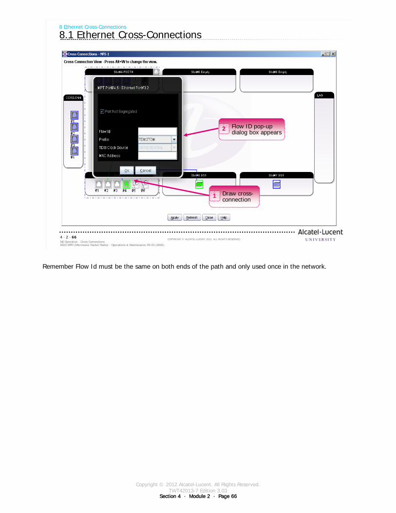
Copyright © 2012 Alcatel-Lucent. All Rights Reserved.TWT42013-7 Edition 3.03
Section 4 · Module 2 · Page 66Section 4 · Module 2 · Page 66
9500 MPR (Microwave Packet Radio) · Operations & Maintenance R3.03 (ANSI)NE Operation · Cross Connections4 · 2 · 66
COPYRIGHT © ALCATEL-LUCENT 2012. ALL RIGHTS RESERVED.
8 Ethernet Cross-Connections
8.1 Ethernet Cross-Connections
Flow ID pop-up dialog box appears
2
Draw cross-connection
1
Remember Flow Id must be the same on both ends of the path and only used once in the network.
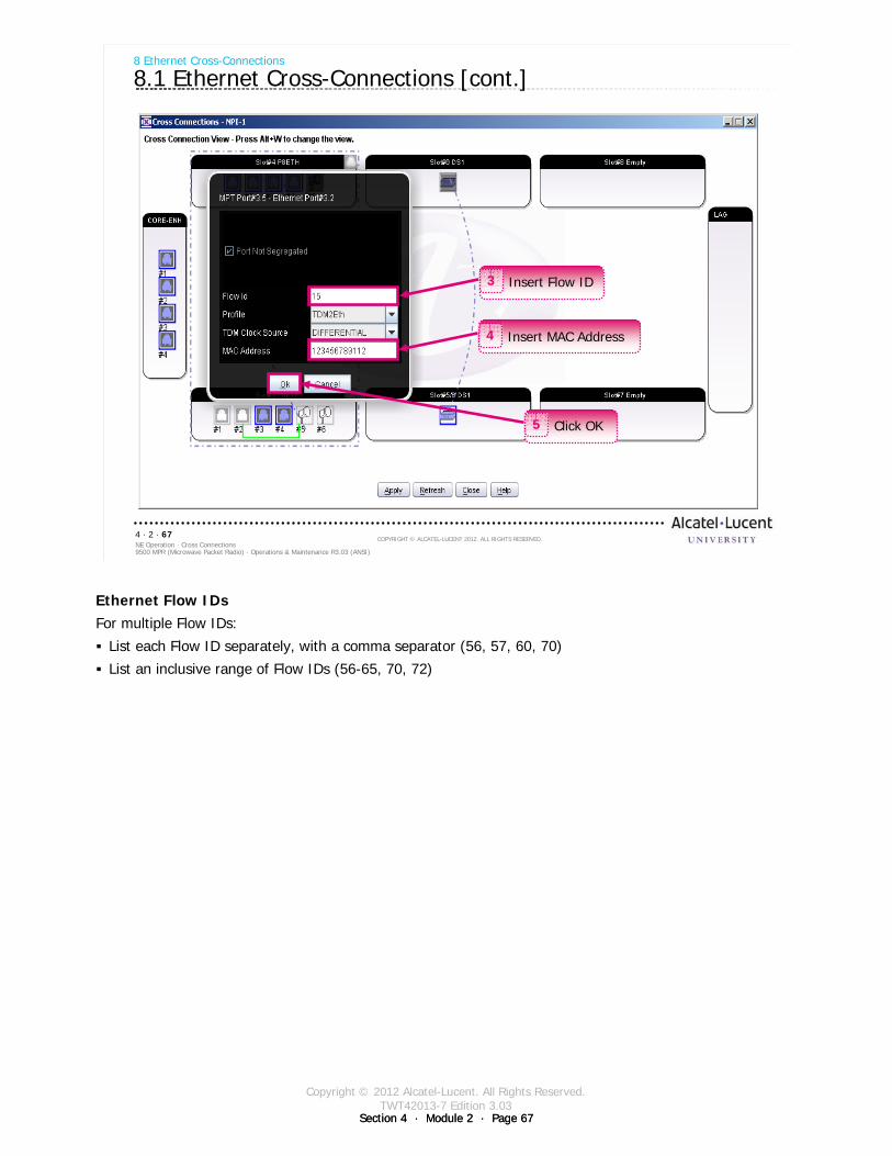
Copyright © 2012 Alcatel-Lucent. All Rights Reserved.TWT42013-7 Edition 3.03
Section 4 · Module 2 · Page 67Section 4 · Module 2 · Page 67
9500 MPR (Microwave Packet Radio) · Operations & Maintenance R3.03 (ANSI)NE Operation · Cross Connections4 · 2 · 67
COPYRIGHT © ALCATEL-LUCENT 2012. ALL RIGHTS RESERVED.
8 Ethernet Cross-Connections
8.1 Ethernet Cross-Connections [cont.]
Insert Flow ID3
Insert MAC Address4
Click OK5
Ethernet Flow IDsFor multiple Flow IDs:
List each Flow ID separately, with a comma separator (56, 57, 60, 70)
List an inclusive range of Flow IDs (56-65, 70, 72)
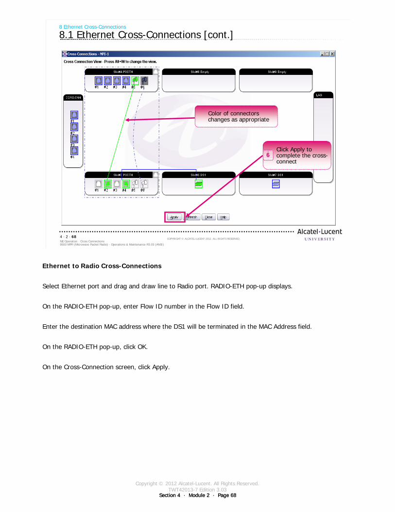
Copyright © 2012 Alcatel-Lucent. All Rights Reserved.TWT42013-7 Edition 3.03
Section 4 · Module 2 · Page 68Section 4 · Module 2 · Page 68
9500 MPR (Microwave Packet Radio) · Operations & Maintenance R3.03 (ANSI)NE Operation · Cross Connections4 · 2 · 68
COPYRIGHT © ALCATEL-LUCENT 2012. ALL RIGHTS RESERVED.
8 Ethernet Cross-Connections
8.1 Ethernet Cross-Connections [cont.]
Click Apply to complete the cross-connect
6
Color of connectors changes as appropriate
Ethernet to Radio Cross-Connections
Select Ethernet port and drag and draw line to Radio port. RADIO-ETH pop-up displays.
On the RADIO-ETH pop-up, enter Flow ID number in the Flow ID field.
Enter the destination MAC address where the DS1 will be terminated in the MAC Address field.
On the RADIO-ETH pop-up, click OK.
On the Cross-Connection screen, click Apply.
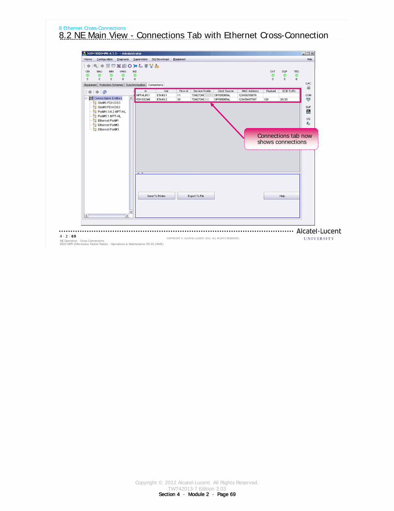
Copyright © 2012 Alcatel-Lucent. All Rights Reserved.TWT42013-7 Edition 3.03
Section 4 · Module 2 · Page 69Section 4 · Module 2 · Page 69
9500 MPR (Microwave Packet Radio) · Operations & Maintenance R3.03 (ANSI)NE Operation · Cross Connections4 · 2 · 69
COPYRIGHT © ALCATEL-LUCENT 2012. ALL RIGHTS RESERVED.
8 Ethernet Cross-Connections
8.2 NE Main View - Connections Tab with Ethernet Cross-Connection
Connections tab now shows connections

Copyright © 2012 Alcatel-Lucent. All Rights Reserved.TWT42013-7 Edition 3.03
Section 4 · Module 2 · Page 70Section 4 · Module 2 · Page 70
9500 MPR (Microwave Packet Radio) · Operations & Maintenance R3.03 (ANSI)NE Operation · Cross Connections4 · 2 · 70
COPYRIGHT © ALCATEL-LUCENT 2012. ALL RIGHTS RESERVED.
Blank page
Switch to notes view!
This page intentionally left blank

Copyright © 2012 Alcatel-Lucent. All Rights Reserved.TWT42013-7 Edition 3.03
Section 4 · Module 2 · Page 71
9500 MPR (Microwave Packet Radio) · Operations & Maintenance R3.03 (ANSI)NE Operation · Cross Connections4 · 2 · 71
COPYRIGHT © ALCATEL-LUCENT 2012. ALL RIGHTS RESERVED.
9 P2P VLAN Cross-Connections
Refer to 9500 MPR Operation and Administration, 3EM23954AHAA, DLP-140 for more details
Copyright © 2012 Alcatel-Lucent. All Rights Reserved.TWT42013-7 Edition 3.03
Section 4 · Module 2 · Page 72Section 4 · Module 2 · Page 72
9500 MPR (Microwave Packet Radio) · Operations & Maintenance R3.03 (ANSI)NE Operation · Cross Connections4 · 2 · 72
COPYRIGHT © ALCATEL-LUCENT 2012. ALL RIGHTS RESERVED.
9 P2P VLAN Cross-Connections
9.1 P2P VLAN Cross-Connections
More than one cross-connection can be drawn if sufficient ports are configured
Cross-connections describe path to use.Segregation describes path not to use.
Each cross-connection must be identified with a separate flow IDThe Point to Point (P2P) VLAN cross-connect allows the user to direct
VLAN-tagged traffic between specified Ethernet and radio portsP2P VLAN must have a MAC Address of 000000000000
Nailed up cross-connections use a physical MAC Address of the device attached to the NE.
Point to Point VLANThe Point to Point (P2P) VLAN cross-connect feature allows the user to direct VLAN-tagged traffic between
specified Ethernet and radio ports. Rather than directing all traffic to and from the cross-connected ports, the feature directs Ethernet traffic where the VLAN tag matches the cross-connect Flow ID. (Flow ID matches VLAN ID.)
When making the connection for a P2P VLAN flow, the user should enter a MAC address of all 0's (000000000000). P2P VLAN cross-connects will direct matching VLAN-tagged Ethernet traffic to the cross-connected ports regardless of the destination MAC address in the Ethernet frames.
Ethernet traffic entering the cross-connected port with a VLAN tag matching the flow id will be directed only to the port on the other end of the cross-connect. Traffic will not be flooded. This will also take precedence over any MAC address learning for VLAN-tagged traffic that matches the flow id in the cross-connect.
Ethernet traffic entering the cross-connected port with no VLAN tag or VLAN tags that do not match the flow id specified in the cross-connect will flood to all ports until MAC address learning takes place. The P2P VLAN cross-connect will have no effect on this traffic.
VLAN tagged Ethernet traffic that enters a port will be dropped if the VLAN tag matches the flow id of a cross-connect that is on a different port.
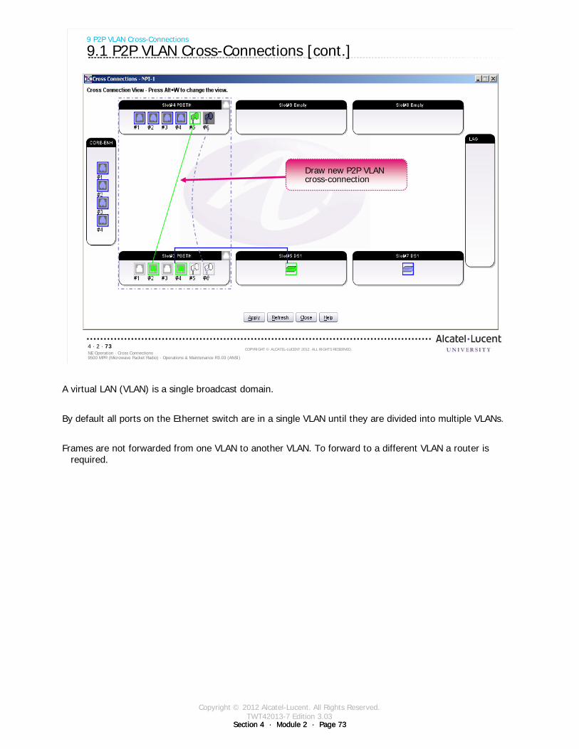
Copyright © 2012 Alcatel-Lucent. All Rights Reserved.TWT42013-7 Edition 3.03
Section 4 · Module 2 · Page 73Section 4 · Module 2 · Page 73
9500 MPR (Microwave Packet Radio) · Operations & Maintenance R3.03 (ANSI)NE Operation · Cross Connections4 · 2 · 73
COPYRIGHT © ALCATEL-LUCENT 2012. ALL RIGHTS RESERVED.
9 P2P VLAN Cross-Connections
9.1 P2P VLAN Cross-Connections [cont.]
Draw new P2P VLAN cross-connection
A virtual LAN (VLAN) is a single broadcast domain.
By default all ports on the Ethernet switch are in a single VLAN until they are divided into multiple VLANs.
Frames are not forwarded from one VLAN to another VLAN. To forward to a different VLAN a router is required.
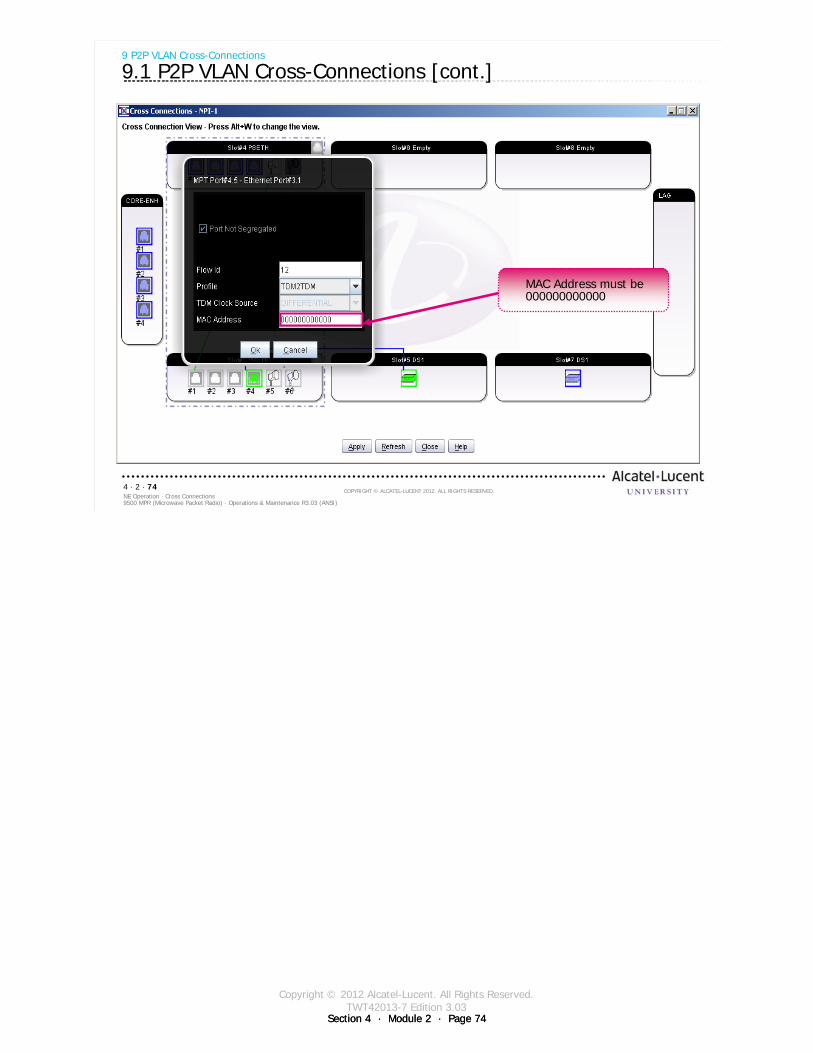
Copyright © 2012 Alcatel-Lucent. All Rights Reserved.TWT42013-7 Edition 3.03
Section 4 · Module 2 · Page 74Section 4 · Module 2 · Page 74
9500 MPR (Microwave Packet Radio) · Operations & Maintenance R3.03 (ANSI)NE Operation · Cross Connections4 · 2 · 74
COPYRIGHT © ALCATEL-LUCENT 2012. ALL RIGHTS RESERVED.
9 P2P VLAN Cross-Connections
9.1 P2P VLAN Cross-Connections [cont.]
MAC Address must be 000000000000

Copyright © 2012 Alcatel-Lucent. All Rights Reserved.TWT42013-7 Edition 3.03
Section 4 · Module 2 · Page 75
9500 MPR (Microwave Packet Radio) · Operations & Maintenance R3.03 (ANSI)NE Operation · Cross Connections4 · 2 · 75
COPYRIGHT © ALCATEL-LUCENT 2012. ALL RIGHTS RESERVED.
10 Radio Cross-Connections
Refer to 9500 MPR Operation and Administration, 3EM23954AHAA, DLP-140 for more details
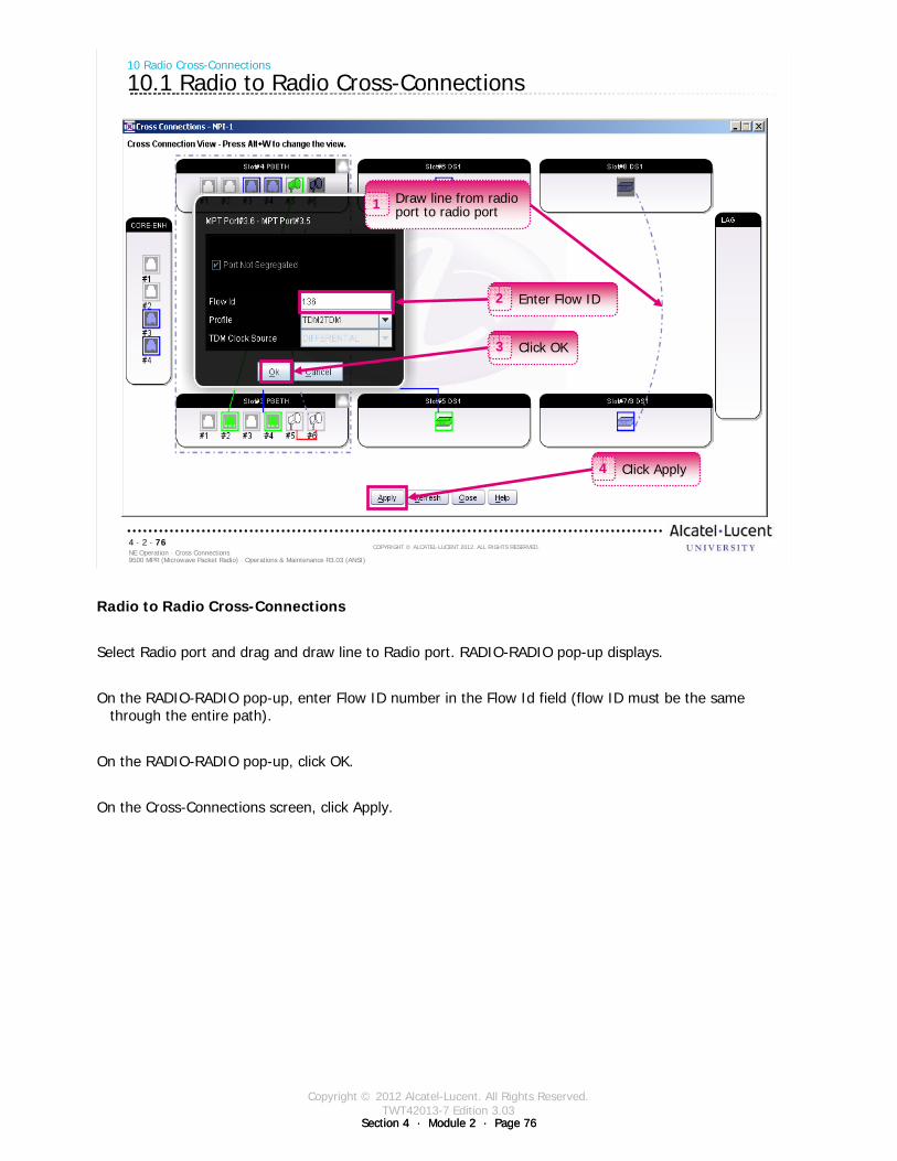
Copyright © 2012 Alcatel-Lucent. All Rights Reserved.TWT42013-7 Edition 3.03
Section 4 · Module 2 · Page 76Section 4 · Module 2 · Page 76
9500 MPR (Microwave Packet Radio) · Operations & Maintenance R3.03 (ANSI)NE Operation · Cross Connections4 · 2 · 76
COPYRIGHT © ALCATEL-LUCENT 2012. ALL RIGHTS RESERVED.
10 Radio Cross-Connections
10.1 Radio to Radio Cross-Connections
Click Apply4
Click OK3
Enter Flow ID2
Draw line from radio port to radio port1
Radio to Radio Cross-Connections
Select Radio port and drag and draw line to Radio port. RADIO-RADIO pop-up displays.
On the RADIO-RADIO pop-up, enter Flow ID number in the Flow Id field (flow ID must be the same through the entire path).
On the RADIO-RADIO pop-up, click OK.
On the Cross-Connections screen, click Apply.

Copyright © 2012 Alcatel-Lucent. All Rights Reserved.TWT42013-7 Edition 3.03
Section 4 · Module 2 · Page 77Section 4 · Module 2 · Page 77
9500 MPR (Microwave Packet Radio) · Operations & Maintenance R3.03 (ANSI)NE Operation · Cross Connections4 · 2 · 77
COPYRIGHT © ALCATEL-LUCENT 2012. ALL RIGHTS RESERVED.
Exercise
Time allowed:
Lab Exercise 11Ethernet Cross-Connections

Copyright © 2012 Alcatel-Lucent. All Rights Reserved.TWT42013-7 Edition 3.03
Section 4 · Module 2 · Page 78Section 4 · Module 2 · Page 78
9500 MPR (Microwave Packet Radio) · Operations & Maintenance R3.03 (ANSI)NE Operation · Cross Connections4 · 2 · 78
COPYRIGHT © ALCATEL-LUCENT 2012. ALL RIGHTS RESERVED.
Blank page
Switch to notes view!
This page intentionally left blank

Copyright © 2012 Alcatel-Lucent. All Rights Reserved.TWT42013-7 Edition 3.03
Section 4 · Module 2 · Page 79Section 4 · Module 2 · Page 79
9500 MPR (Microwave Packet Radio) · Operations & Maintenance R3.03 (ANSI)NE Operation · Cross Connections4 · 2 · 79
COPYRIGHT © ALCATEL-LUCENT 2012. ALL RIGHTS RESERVED.
Module summary
Configure DS1 portsDescribe cross-connectionsConfigure DS1 cross-connections Configure DS3 portsConfigure DS3 cross-connectionsConfigure Ethernet portsDescribe port segregation Configure Ethernet (P2P VLAN) cross-connectionsConfigure radio cross-connections

Copyright © 2012 Alcatel-Lucent. All Rights Reserved.TWT42013-7 Edition 3.03
Section 4 · Module 2 · Page 80Section 4 · Module 2 · Page 80
9500 MPR (Microwave Packet Radio) · Operations & Maintenance R3.03 (ANSI)NE Operation · Cross Connections4 · 2 · 80
COPYRIGHT © ALCATEL-LUCENT 2012. ALL RIGHTS RESERVED.
End of moduleCross Connections

Copyright © 2012 Alcatel-Lucent. All Rights Reserved.TWT42013-8 Edition 3.03
Section 4 · Module 3 · Page 1
Do not delete this graphic elements in here:
All Rights Reserved © Alcatel-Lucent @@YEAR
Module 3Performance Monitoring
TWT42013-8 Edition 3.03
Section 4NE Operation
9500 MPR (Microwave Packet Radio)Operations & Maintenance R3.03 (ANSI)
TWT42013 Edition 1.1

Copyright © 2012 Alcatel-Lucent. All Rights Reserved.TWT42013-8 Edition 3.03
Section 4 · Module 3 · Page 2
9500 MPR (Microwave Packet Radio) · Operations & Maintenance R3.03 (ANSI)NE Operation · Performance Monitoring4 · 3 · 2
COPYRIGHT © ALCATEL-LUCENT 2012. ALL RIGHTS RESERVED.
Blank page
This page is left blank intentionally
Document History
Edition Date Author Remarks
01.42 2009-08-04 Robinson, Ken First edition
2.01 2010-07-30 Moehlenkamp, John Revised to release 2.01
2.02 2010-11-30 Moehlenkamp, John Revised to release 2.02
3.0 2011-02-28 Moehlenkamp, John Revised to release 3.0
3.01 2011-06-29 Moehlenkamp, John Revised to release 3.01
3.02 2011-11-15 Moehlenkamp, John Updated format and revised to release 3.02
3.03 2012-02-07 Moehlenkamp, John Revised to release 3.03
Copyright © 2012 Alcatel-Lucent. All Rights Reserved.TWT42013-8 Edition 3.03
Section 4 · Module 3 · Page 3
9500 MPR (Microwave Packet Radio) · Operations & Maintenance R3.03 (ANSI)NE Operation · Performance Monitoring4 · 3 · 3
COPYRIGHT © ALCATEL-LUCENT 2012. ALL RIGHTS RESERVED.
Module objectives
Upon completion of this module, you should be able to sse the menus and tabs to observe the 9500 MPR-A Network Element’s performance:
Power MeasurementsAlarmsEvent LogRemote InventoryAbnormal Condition ListSummary Block Diagram ViewCurrent Configuration ViewPerformance Monitoring IconLoopback

Copyright © 2012 Alcatel-Lucent. All Rights Reserved.TWT42013-8 Edition 3.03
Section 4 · Module 3 · Page 4
9500 MPR (Microwave Packet Radio) · Operations & Maintenance R3.03 (ANSI)NE Operation · Performance Monitoring4 · 3 · 4
COPYRIGHT © ALCATEL-LUCENT 2012. ALL RIGHTS RESERVED.
Module objectives [cont.]
This page is left blank intentionally
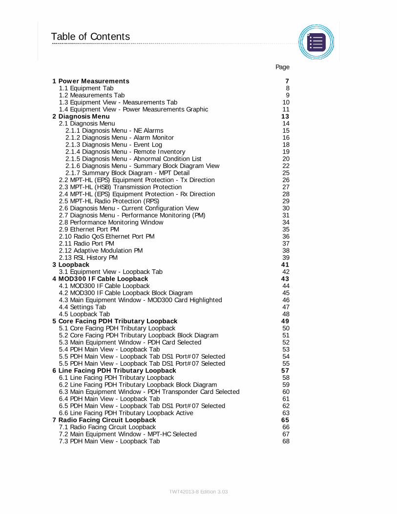
Copyright © 2012 Alcatel-Lucent. All Rights Reserved.TWT42013-8 Edition 3.03
9500 MPR (Microwave Packet Radio) · Operations & Maintenance R3.03 (ANSI)NE Operation · Performance Monitoring4 · 3 · 5
COPYRIGHT © ALCATEL-LUCENT 2012. ALL RIGHTS RESERVED.
Table of Contents
Switch to notes view! Page
1 Power Measurements 71.1 Equipment Tab 81.2 Measurements Tab 91.3 Equipment View - Measurements Tab 101.4 Equipment View - Power Measurements Graphic 11
2 Diagnosis Menu 132.1 Diagnosis Menu 14
2.1.1 Diagnosis Menu - NE Alarms 152.1.2 Diagnosis Menu - Alarm Monitor 162.1.3 Diagnosis Menu - Event Log 182.1.4 Diagnosis Menu - Remote Inventory 192.1.5 Diagnosis Menu - Abnormal Condition List 202.1.6 Diagnosis Menu - Summary Block Diagram View 222.1.7 Summary Block Diagram - MPT Detail 25
2.2 MPT-HL (EPS) Equipment Protection - Tx Direction 262.3 MPT-HL (HSB) Transmission Protection 272.4 MPT-HL (EPS) Equipment Protection - Rx Direction 282.5 MPT-HL Radio Protection (RPS) 292.6 Diagnosis Menu - Current Configuration View 302.7 Diagnosis Menu - Performance Monitoring (PM) 312.8 Performance Monitoring Window 342.9 Ethernet Port PM 352.10 Radio QoS Ethernet Port PM 362.11 Radio Port PM 372.12 Adaptive Modulation PM 382.13 RSL History PM 39
3 Loopback 413.1 Equipment View - Loopback Tab 42
4 MOD300 IF Cable Loopback 434.1 MOD300 IF Cable Loopback 444.2 MOD300 IF Cable Loopback Block Diagram 454.3 Main Equipment Window - MOD300 Card Highlighted 464.4 Settings Tab 474.5 Loopback Tab 48
5 Core Facing PDH Tributary Loopback 495.1 Core Facing PDH Tributary Loopback 505.2 Core Facing PDH Tributary Loopback Block Diagram 515.3 Main Equipment Window - PDH Card Selected 525.4 PDH Main View - Loopback Tab 535.5 PDH Main View - Loopback Tab DS1 Port#07 Selected 545.5 PDH Main View - Loopback Tab DS1 Port#07 Selected 55
6 Line Facing PDH Tributary Loopback 576.1 Line Facing PDH Tributary Loopback 586.2 Line Facing PDH Tributary Loopback Block Diagram 596.3 Main Equipment Window - PDH Transponder Card Selected 606.4 PDH Main View - Loopback Tab 616.5 PDH Main View - Loopback Tab DS1 Port#07 Selected 626.6 Line Facing PDH Tributary Loopback Active 63
7 Radio Facing Circuit Loopback 657.1 Radio Facing Circuit Loopback 667.2 Main Equipment Window - MPT-HC Selected 677.3 PDH Main View - Loopback Tab 68

Copyright © 2012 Alcatel-Lucent. All Rights Reserved.TWT42013-8 Edition 3.03
9500 MPR (Microwave Packet Radio) · Operations & Maintenance R3.03 (ANSI)NE Operation · Performance Monitoring4 · 3 · 6
COPYRIGHT © ALCATEL-LUCENT 2012. ALL RIGHTS RESERVED.
Table of Contents [cont.]
Switch to notes view! Page

Copyright © 2012 Alcatel-Lucent. All Rights Reserved.TWT42013-8 Edition 3.03
Section 4 · Module 3 · Page 7
9500 MPR (Microwave Packet Radio) · Operations & Maintenance R3.03 (ANSI)NE Operation · Performance Monitoring4 · 3 · 7
COPYRIGHT © ALCATEL-LUCENT 2012. ALL RIGHTS RESERVED.
1 Power Measurements
Refer to 9500 MPR Operation and Administration, 3EM23954AHAA, DLP-123 for more details
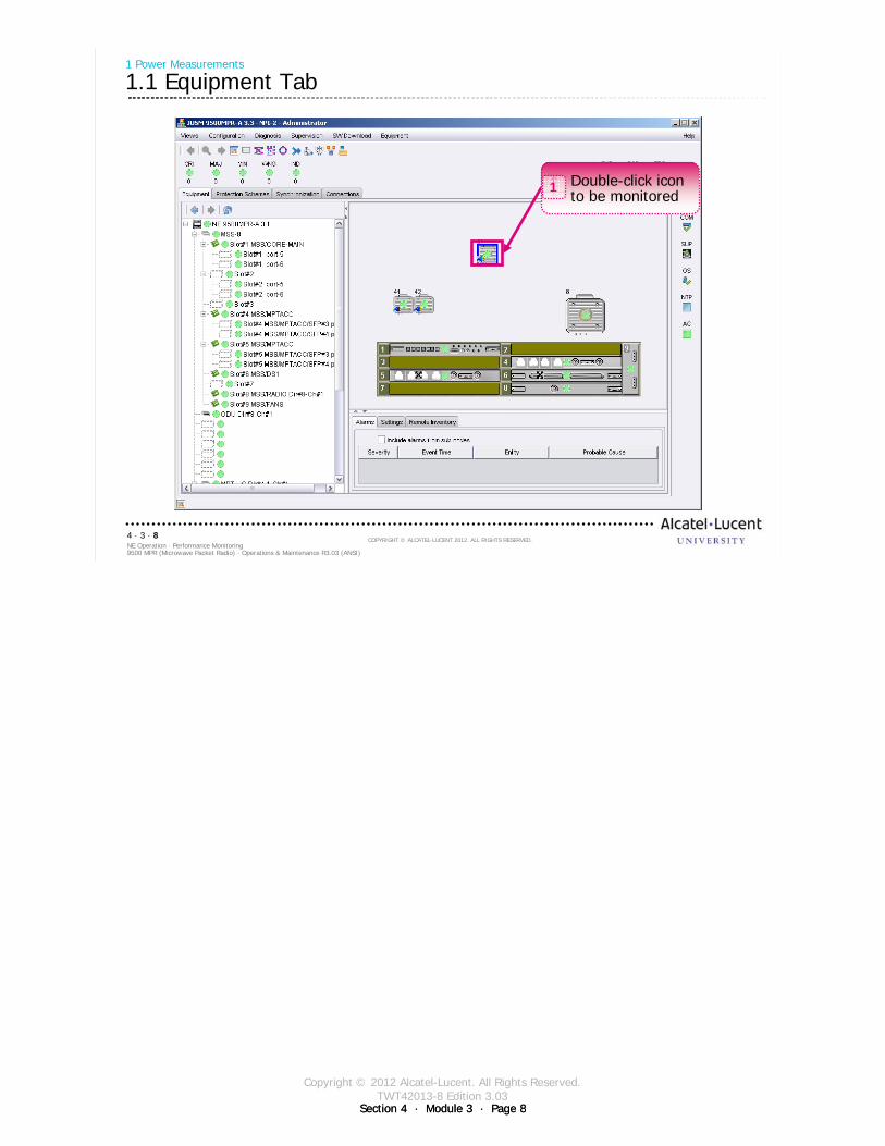
Copyright © 2012 Alcatel-Lucent. All Rights Reserved.TWT42013-8 Edition 3.03
Section 4 · Module 3 · Page 8Section 4 · Module 3 · Page 8
9500 MPR (Microwave Packet Radio) · Operations & Maintenance R3.03 (ANSI)NE Operation · Performance Monitoring4 · 3 · 8
COPYRIGHT © ALCATEL-LUCENT 2012. ALL RIGHTS RESERVED.
1 Power Measurements
1.1 Equipment Tab
Double-click icon to be monitored
1
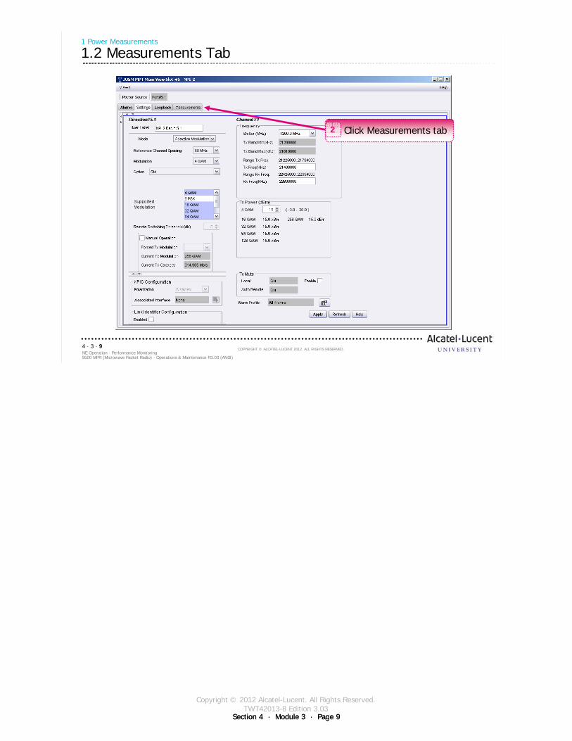
Copyright © 2012 Alcatel-Lucent. All Rights Reserved.TWT42013-8 Edition 3.03
Section 4 · Module 3 · Page 9Section 4 · Module 3 · Page 9
9500 MPR (Microwave Packet Radio) · Operations & Maintenance R3.03 (ANSI)NE Operation · Performance Monitoring4 · 3 · 9
COPYRIGHT © ALCATEL-LUCENT 2012. ALL RIGHTS RESERVED.
1 Power Measurements
1.2 Measurements Tab
Click Measurements tab2
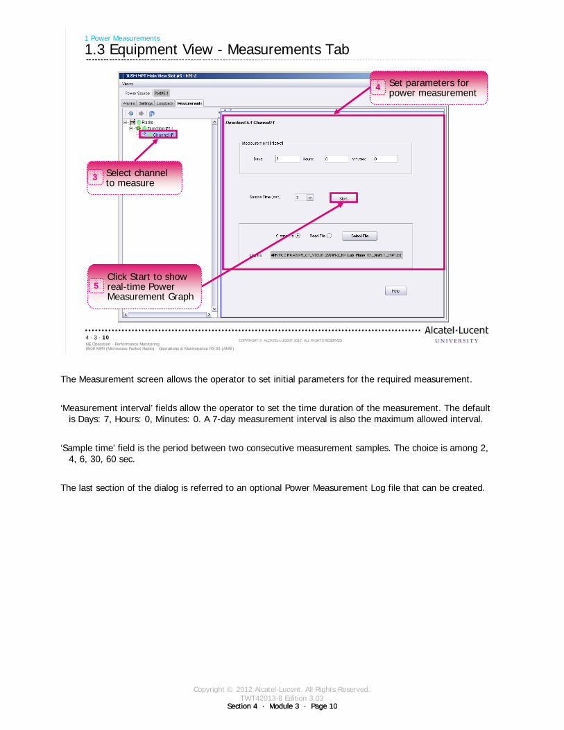
Copyright © 2012 Alcatel-Lucent. All Rights Reserved.TWT42013-8 Edition 3.03
Section 4 · Module 3 · Page 10Section 4 · Module 3 · Page 10
9500 MPR (Microwave Packet Radio) · Operations & Maintenance R3.03 (ANSI)NE Operation · Performance Monitoring4 · 3 · 10
COPYRIGHT © ALCATEL-LUCENT 2012. ALL RIGHTS RESERVED.
1 Power Measurements
1.3 Equipment View - Measurements Tab
Select channel to measure
3
Set parameters for power measurement
4
Click Start to show real-time Power Measurement Graph
5
The Measurement screen allows the operator to set initial parameters for the required measurement.
‘Measurement interval’ fields allow the operator to set the time duration of the measurement. The default is Days: 7, Hours: 0, Minutes: 0. A 7-day measurement interval is also the maximum allowed interval.
‘Sample time’ field is the period between two consecutive measurement samples. The choice is among 2, 4, 6, 30, 60 sec.
The last section of the dialog is referred to an optional Power Measurement Log file that can be created.
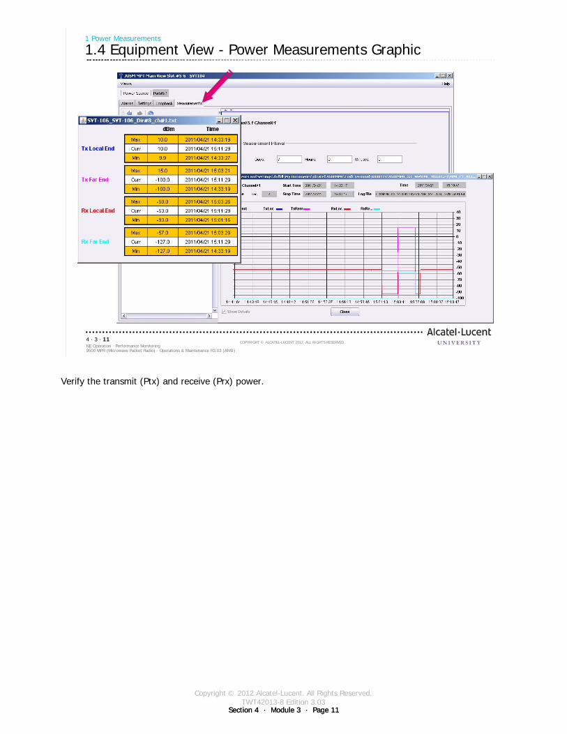
Copyright © 2012 Alcatel-Lucent. All Rights Reserved.TWT42013-8 Edition 3.03
Section 4 · Module 3 · Page 11Section 4 · Module 3 · Page 11
9500 MPR (Microwave Packet Radio) · Operations & Maintenance R3.03 (ANSI)NE Operation · Performance Monitoring4 · 3 · 11
COPYRIGHT © ALCATEL-LUCENT 2012. ALL RIGHTS RESERVED.
1 Power Measurements
1.4 Equipment View - Power Measurements Graphic
Verify the transmit (Ptx) and receive (Prx) power.
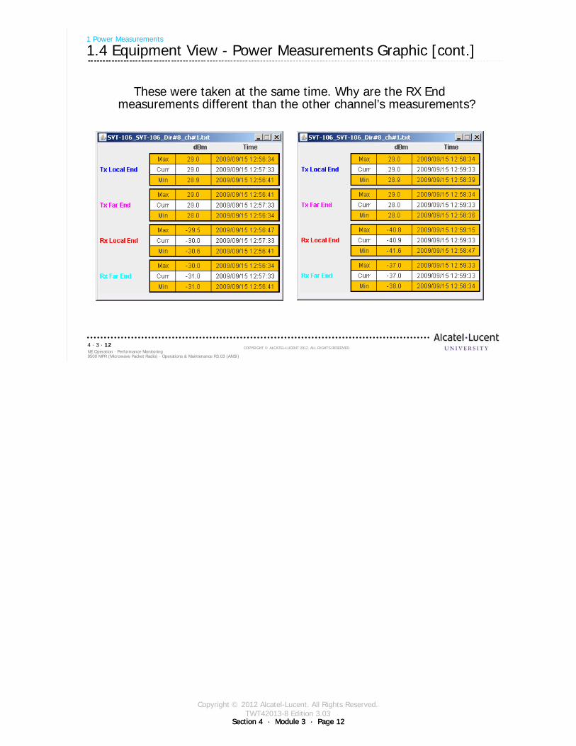
Copyright © 2012 Alcatel-Lucent. All Rights Reserved.TWT42013-8 Edition 3.03
Section 4 · Module 3 · Page 12Section 4 · Module 3 · Page 12
9500 MPR (Microwave Packet Radio) · Operations & Maintenance R3.03 (ANSI)NE Operation · Performance Monitoring4 · 3 · 12
COPYRIGHT © ALCATEL-LUCENT 2012. ALL RIGHTS RESERVED.
1 Power Measurements
1.4 Equipment View - Power Measurements Graphic [cont.]
These were taken at the same time. Why are the RX End measurements different than the other channel’s measurements?

Copyright © 2012 Alcatel-Lucent. All Rights Reserved.TWT42013-8 Edition 3.03
Section 4 · Module 3 · Page 13
9500 MPR (Microwave Packet Radio) · Operations & Maintenance R3.03 (ANSI)NE Operation · Performance Monitoring4 · 3 · 13
COPYRIGHT © ALCATEL-LUCENT 2012. ALL RIGHTS RESERVED.
2 Diagnosis Menu
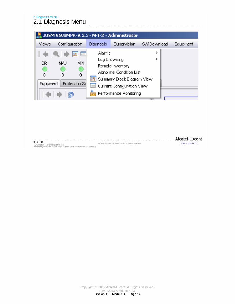
Copyright © 2012 Alcatel-Lucent. All Rights Reserved.TWT42013-8 Edition 3.03
Section 4 · Module 3 · Page 14Section 4 · Module 3 · Page 14
9500 MPR (Microwave Packet Radio) · Operations & Maintenance R3.03 (ANSI)NE Operation · Performance Monitoring4 · 3 · 14
COPYRIGHT © ALCATEL-LUCENT 2012. ALL RIGHTS RESERVED.
2 Diagnosis Menu
2.1 Diagnosis Menu
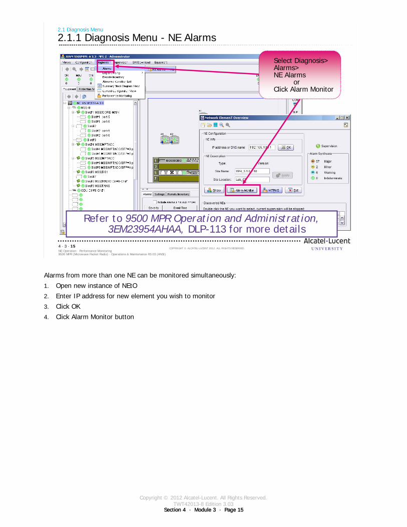
Copyright © 2012 Alcatel-Lucent. All Rights Reserved.TWT42013-8 Edition 3.03
Section 4 · Module 3 · Page 15Section 4 · Module 3 · Page 15
9500 MPR (Microwave Packet Radio) · Operations & Maintenance R3.03 (ANSI)NE Operation · Performance Monitoring4 · 3 · 15
COPYRIGHT © ALCATEL-LUCENT 2012. ALL RIGHTS RESERVED.
2.1 Diagnosis Menu
2.1.1 Diagnosis Menu - NE Alarms
Refer to 9500 MPR Operation and Administration, 3EM23954AHAA, DLP-113 for more details
Select Diagnosis>Alarms>NE Alarms
orClick Alarm Monitor
Alarms from more than one NE can be monitored simultaneously:
1. Open new instance of NEtO
2. Enter IP address for new element you wish to monitor
3. Click OK
4. Click Alarm Monitor button
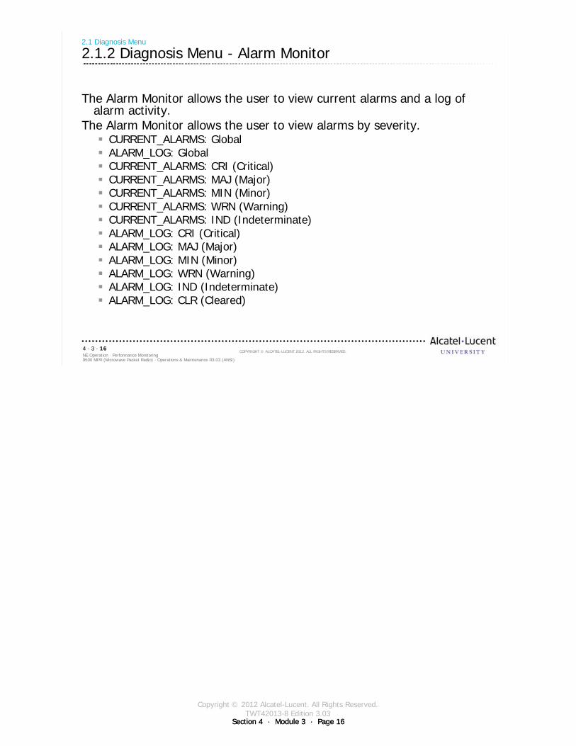
Copyright © 2012 Alcatel-Lucent. All Rights Reserved.TWT42013-8 Edition 3.03
Section 4 · Module 3 · Page 16Section 4 · Module 3 · Page 16
9500 MPR (Microwave Packet Radio) · Operations & Maintenance R3.03 (ANSI)NE Operation · Performance Monitoring4 · 3 · 16
COPYRIGHT © ALCATEL-LUCENT 2012. ALL RIGHTS RESERVED.
2.1 Diagnosis Menu
2.1.2 Diagnosis Menu - Alarm Monitor
The Alarm Monitor allows the user to view current alarms and a log of alarm activity.
The Alarm Monitor allows the user to view alarms by severity.CURRENT_ALARMS: GlobalALARM_LOG: GlobalCURRENT_ALARMS: CRI (Critical)CURRENT_ALARMS: MAJ (Major)CURRENT_ALARMS: MIN (Minor)CURRENT_ALARMS: WRN (Warning)CURRENT_ALARMS: IND (Indeterminate)ALARM_LOG: CRI (Critical)ALARM_LOG: MAJ (Major)ALARM_LOG: MIN (Minor)ALARM_LOG: WRN (Warning)ALARM_LOG: IND (Indeterminate)ALARM_LOG: CLR (Cleared)
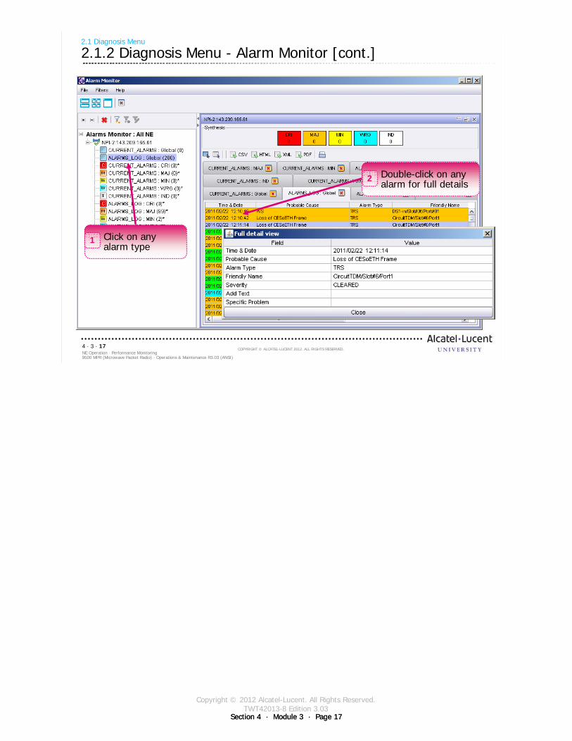
Copyright © 2012 Alcatel-Lucent. All Rights Reserved.TWT42013-8 Edition 3.03
Section 4 · Module 3 · Page 17Section 4 · Module 3 · Page 17
9500 MPR (Microwave Packet Radio) · Operations & Maintenance R3.03 (ANSI)NE Operation · Performance Monitoring4 · 3 · 17
COPYRIGHT © ALCATEL-LUCENT 2012. ALL RIGHTS RESERVED.
2.1 Diagnosis Menu
2.1.2 Diagnosis Menu - Alarm Monitor [cont.]
Click on any alarm type
1
Double-click on any alarm for full details
2
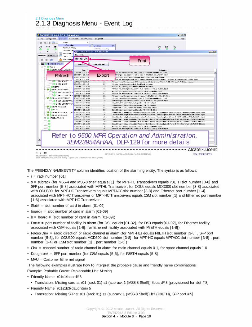
Copyright © 2012 Alcatel-Lucent. All Rights Reserved.TWT42013-8 Edition 3.03
Section 4 · Module 3 · Page 18Section 4 · Module 3 · Page 18
9500 MPR (Microwave Packet Radio) · Operations & Maintenance R3.03 (ANSI)NE Operation · Performance Monitoring4 · 3 · 18
COPYRIGHT © ALCATEL-LUCENT 2012. ALL RIGHTS RESERVED.
2.1 Diagnosis Menu
2.1.3 Diagnosis Menu - Event Log
Refer to 9500 MPR Operation and Administration, 3EM23954AHAA, DLP-129 for more details
ExportRefresh
The FRIENDLY NAME/ENTITY column identifies location of the alarming entity. The syntax is as follows:
r = rack number [01]
s = subrack (for MSS-4 and MSS-8 shelf equals [1], for MPT-HL Transceivers equals P8ETH slot number [3-8] and SFP port number [5-8] associated with MPTHL Transceiver, for ODUs equals MOD300 slot number [3-8] associated with ODU300, for MPT-HC Transceivers equals MPTACC slot number [3-8] and Ethernet port number [1-4] associated with MPT-HC Transceiver or MPT-HC Transceivers equals CSM slot number [1] and Ethernet port number [1-6] associated with MPT-HC Transceiver
Slot# = slot number of card in alarm [01-09]
board# = slot number of card in alarm [01-09]
b = board # (slot number of card in alarm [01-09])
Port# = port number of facility in alarm (for DS1 equals [01-32], for DS3 equals [01-02], for Ethernet facility associated with CSM equals [1-6], for Ethernet facility associated with P8ETH equals [1-8])
Radio/Dir# = radio direction of radio channel in alarm (for MPT-HLs equals P8ETH slot number [3-8] . SFP port number [5-8], for ODU300 equals MOD300 slot number [3-8], for MPT-HC equals MPTACC slot number [3-8] . port number [1-4] or CSM slot number [1] . port number [1-6])
Ch# = channel number of radio channel in alarm for main channel equals 0 1, for spare channel equals 1 0
Daughter# = SFP port number (for CSM equals [5-6], for P8ETH equals [5-8]
MAU = Customer Ethernet signal
The following examples illustrate how to interpret the probable cause and friendly name combinations:
Example: Probable Cause: Replaceable Unit Missing
Friendly Name: r01s1/board#8
Translation: Missing card at r01 (rack 01) s1 (subrack 1 (MSS-8 Shelf)) /board#8 [provisioned for slot #8]
Friendly Name: r01s1b3/daughter#5
• Translation: Missing SFP at r01 (rack 01) s1 (subrack 1 (MSS-8 Shelf)) b3 (P8ETH), SFP port #5]
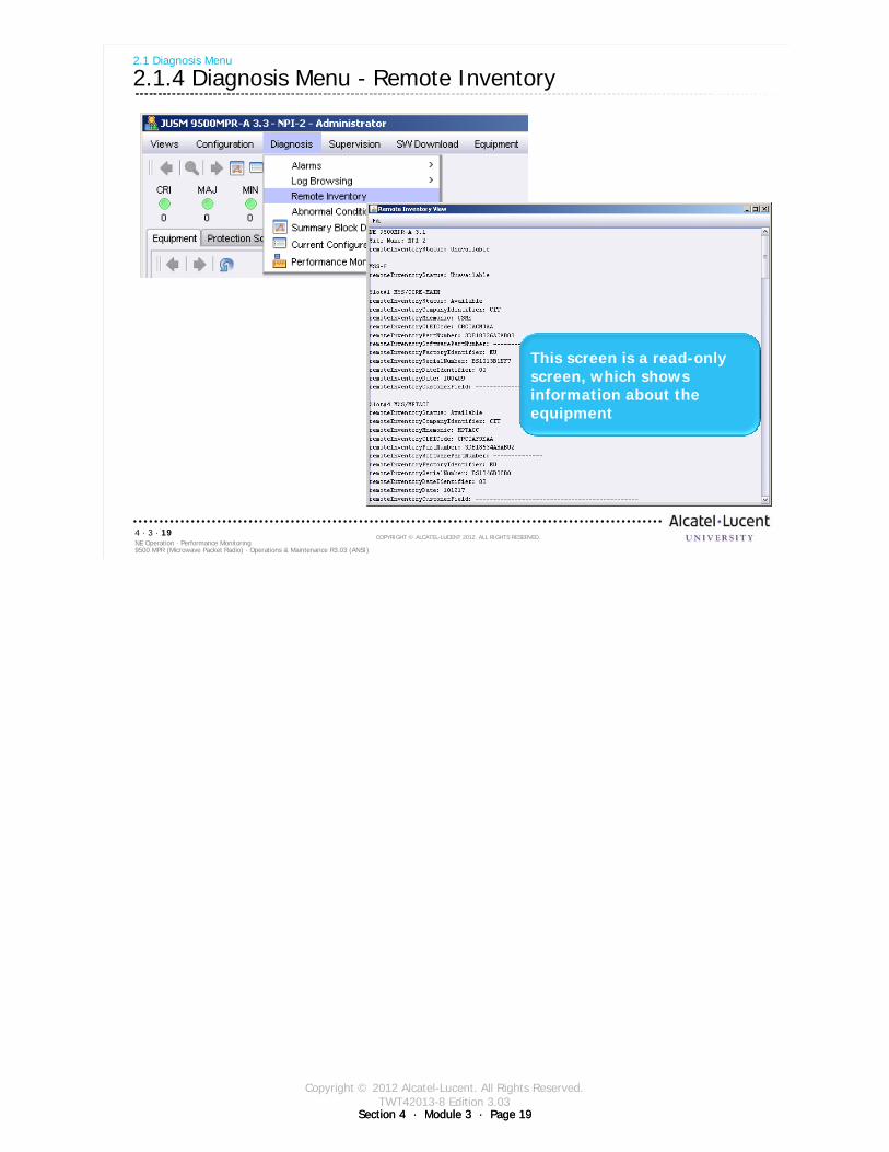
Copyright © 2012 Alcatel-Lucent. All Rights Reserved.TWT42013-8 Edition 3.03
Section 4 · Module 3 · Page 19Section 4 · Module 3 · Page 19
9500 MPR (Microwave Packet Radio) · Operations & Maintenance R3.03 (ANSI)NE Operation · Performance Monitoring4 · 3 · 19
COPYRIGHT © ALCATEL-LUCENT 2012. ALL RIGHTS RESERVED.
2.1 Diagnosis Menu
2.1.4 Diagnosis Menu - Remote Inventory
This screen is a read-only screen, which shows information about the equipment
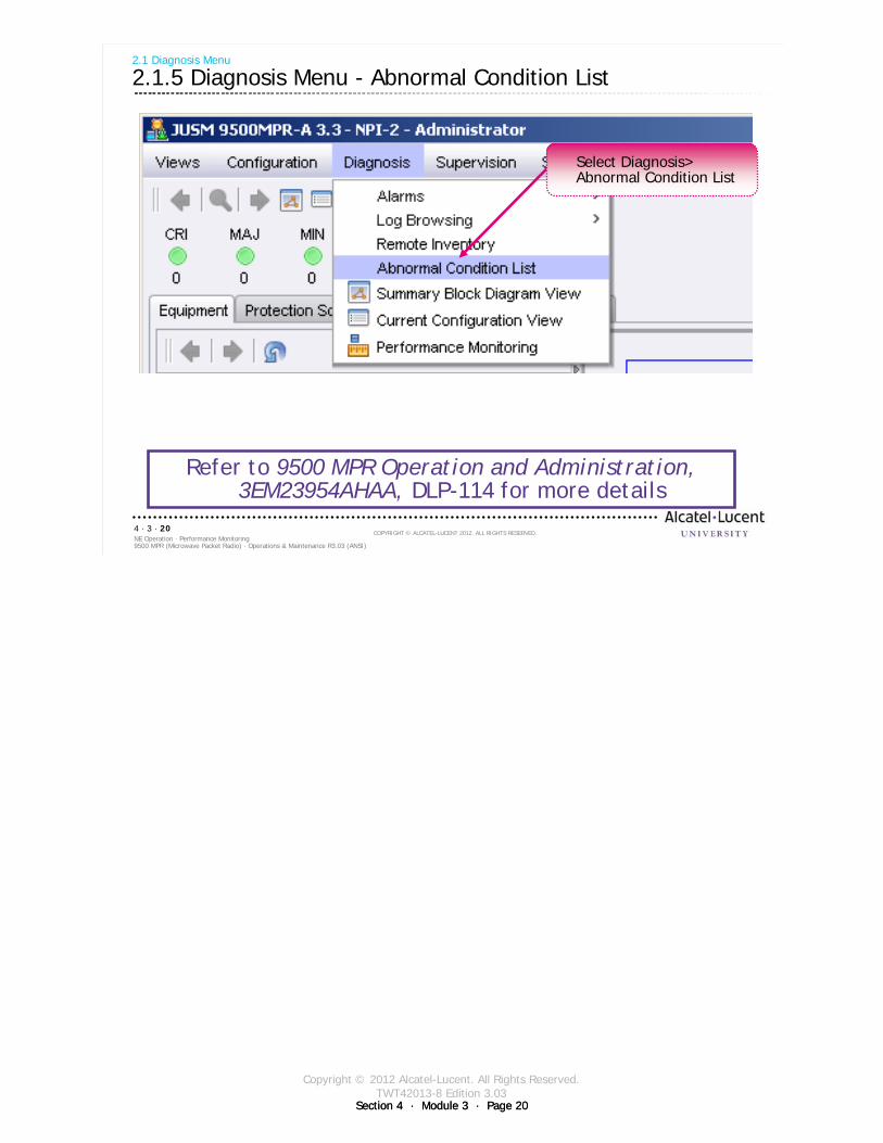
Copyright © 2012 Alcatel-Lucent. All Rights Reserved.TWT42013-8 Edition 3.03
Section 4 · Module 3 · Page 20Section 4 · Module 3 · Page 20
9500 MPR (Microwave Packet Radio) · Operations & Maintenance R3.03 (ANSI)NE Operation · Performance Monitoring4 · 3 · 20
COPYRIGHT © ALCATEL-LUCENT 2012. ALL RIGHTS RESERVED.
2.1 Diagnosis Menu
2.1.5 Diagnosis Menu - Abnormal Condition List
Refer to 9500 MPR Operation and Administration, 3EM23954AHAA, DLP-114 for more details
Select Diagnosis>Abnormal Condition List
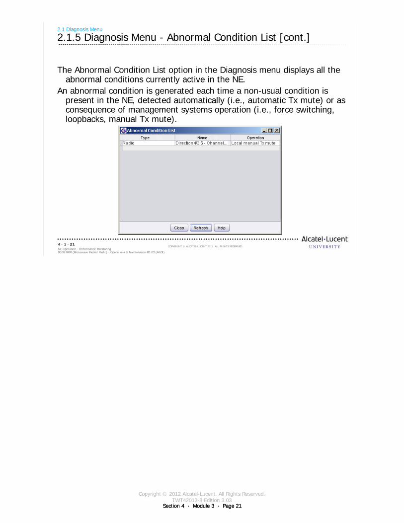
Copyright © 2012 Alcatel-Lucent. All Rights Reserved.TWT42013-8 Edition 3.03
Section 4 · Module 3 · Page 21Section 4 · Module 3 · Page 21
9500 MPR (Microwave Packet Radio) · Operations & Maintenance R3.03 (ANSI)NE Operation · Performance Monitoring4 · 3 · 21
COPYRIGHT © ALCATEL-LUCENT 2012. ALL RIGHTS RESERVED.
2.1 Diagnosis Menu
2.1.5 Diagnosis Menu - Abnormal Condition List [cont.]
The Abnormal Condition List option in the Diagnosis menu displays all the abnormal conditions currently active in the NE.
An abnormal condition is generated each time a non-usual condition is present in the NE, detected automatically (i.e., automatic Tx mute) or as consequence of management systems operation (i.e., force switching, loopbacks, manual Tx mute).
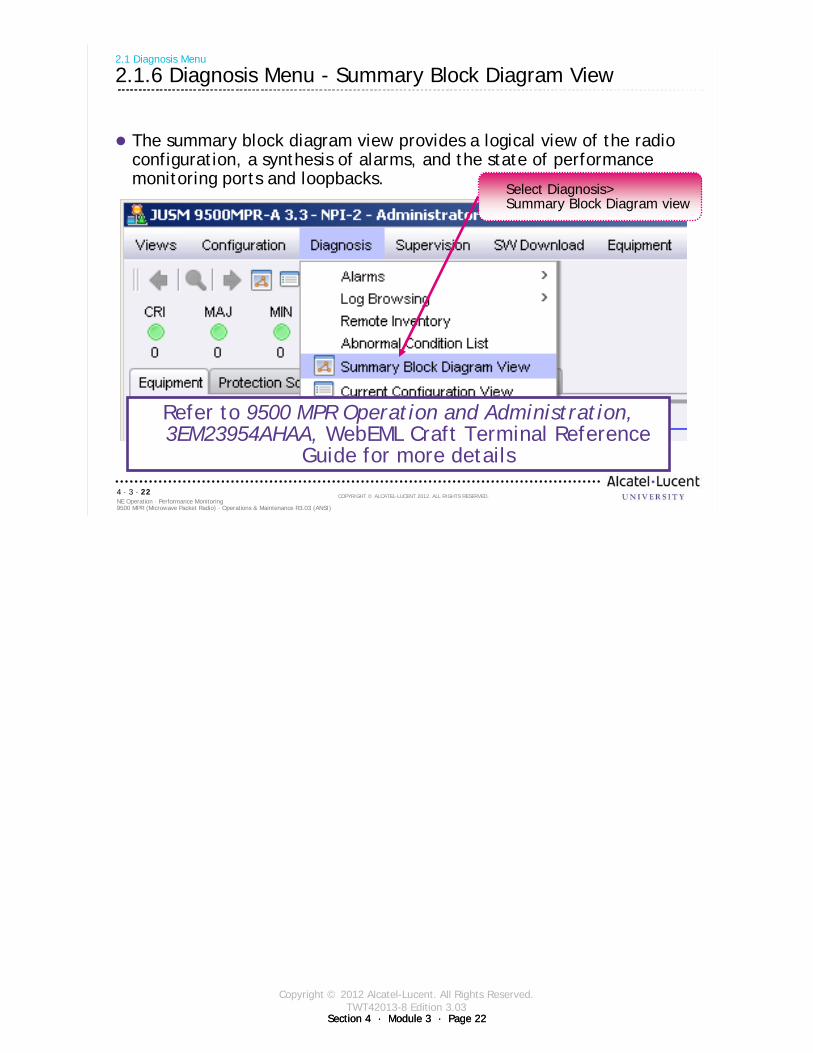
Copyright © 2012 Alcatel-Lucent. All Rights Reserved.TWT42013-8 Edition 3.03
Section 4 · Module 3 · Page 22Section 4 · Module 3 · Page 22
9500 MPR (Microwave Packet Radio) · Operations & Maintenance R3.03 (ANSI)NE Operation · Performance Monitoring4 · 3 · 22
COPYRIGHT © ALCATEL-LUCENT 2012. ALL RIGHTS RESERVED.
The summary block diagram view provides a logical view of the radio configuration, a synthesis of alarms, and the state of performance monitoring ports and loopbacks.
2.1 Diagnosis Menu
2.1.6 Diagnosis Menu - Summary Block Diagram View
Refer to 9500 MPR Operation and Administration, 3EM23954AHAA, WebEML Craft Terminal Reference
Guide for more details
Select Diagnosis>Summary Block Diagram view

Copyright © 2012 Alcatel-Lucent. All Rights Reserved.TWT42013-8 Edition 3.03
Section 4 · Module 3 · Page 23Section 4 · Module 3 · Page 23
9500 MPR (Microwave Packet Radio) · Operations & Maintenance R3.03 (ANSI)NE Operation · Performance Monitoring4 · 3 · 23
COPYRIGHT © ALCATEL-LUCENT 2012. ALL RIGHTS RESERVED.
2.1 Diagnosis Menu
2.1.6 Diagnosis Menu - Summary Block Diagram View [cont.]
Each entity has an alarm indicator (colored ball icon) which indicates its status. The alarm indicators update automatically with changes to the entity alarm status.
The current configuration of the MSS-8 shelf is displayed including the equipped card types (CSM-E/Core-E, PDH [DS1/3], MPTACC, MOD300, or EAS/P8ETH), provisioned protection schemes, and provisioned cross-connections between the different equipment ports.
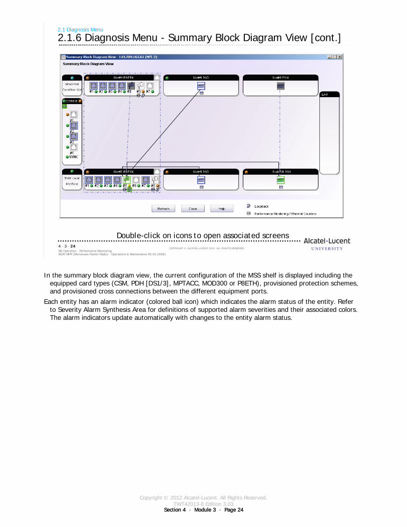
Copyright © 2012 Alcatel-Lucent. All Rights Reserved.TWT42013-8 Edition 3.03
Section 4 · Module 3 · Page 24Section 4 · Module 3 · Page 24
9500 MPR (Microwave Packet Radio) · Operations & Maintenance R3.03 (ANSI)NE Operation · Performance Monitoring4 · 3 · 24
COPYRIGHT © ALCATEL-LUCENT 2012. ALL RIGHTS RESERVED.
2.1 Diagnosis Menu
2.1.6 Diagnosis Menu - Summary Block Diagram View [cont.]
Double-click on icons to open associated screens
In the summary block diagram view, the current configuration of the MSS shelf is displayed including the equipped card types (CSM, PDH [DS1/3], MPTACC, MOD300 or P8ETH), provisioned protection schemes, and provisioned cross connections between the different equipment ports.
Each entity has an alarm indicator (colored ball icon) which indicates the alarm status of the entity. Refer to Severity Alarm Synthesis Area for definitions of supported alarm severities and their associated colors. The alarm indicators update automatically with changes to the entity alarm status.
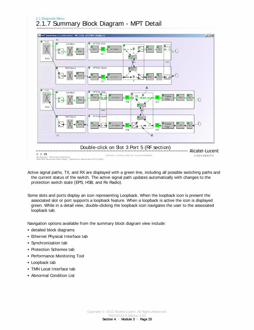
Copyright © 2012 Alcatel-Lucent. All Rights Reserved.TWT42013-8 Edition 3.03
Section 4 · Module 3 · Page 25Section 4 · Module 3 · Page 25
9500 MPR (Microwave Packet Radio) · Operations & Maintenance R3.03 (ANSI)NE Operation · Performance Monitoring4 · 3 · 25
COPYRIGHT © ALCATEL-LUCENT 2012. ALL RIGHTS RESERVED.
2.1 Diagnosis Menu
2.1.7 Summary Block Diagram - MPT Detail
Double-click on Slot 3 Port 5 (RF section)
Active signal paths, TX, and RX are displayed with a green line, including all possible switching paths and the current status of the switch. The active signal path updates automatically with changes to the protection switch state (EPS, HSB, and Rx Radio).
Some slots and ports display an icon representing Loopback. When the loopback icon is present the associated slot or port supports a loopback feature. When a loopback is active the icon is displayed green. While in a detail view, double-clicking the loopback icon navigates the user to the associated loopback tab.
Navigation options available from the summary block diagram view include:
detailed block diagrams
Ethernet Physical Interface tab
Synchronization tab
Protection Schemes tab
Performance Monitoring Tool
Loopback tab
TMN Local Interface tab
Abnormal Condition List
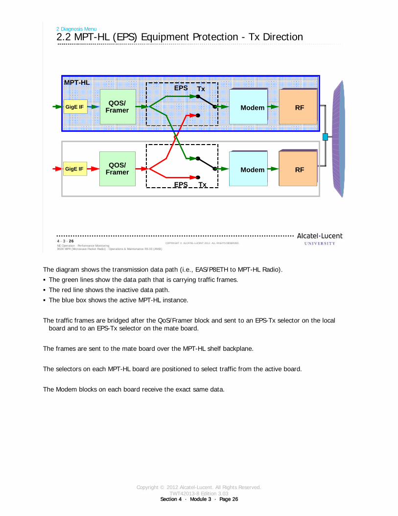
Copyright © 2012 Alcatel-Lucent. All Rights Reserved.TWT42013-8 Edition 3.03
Section 4 · Module 3 · Page 26Section 4 · Module 3 · Page 26
9500 MPR (Microwave Packet Radio) · Operations & Maintenance R3.03 (ANSI)NE Operation · Performance Monitoring4 · 3 · 26
COPYRIGHT © ALCATEL-LUCENT 2012. ALL RIGHTS RESERVED.
GigE IF
2 Diagnosis Menu
2.2 MPT-HL (EPS) Equipment Protection - Tx Direction
/Framer
MPT-HL
Modem
Modem
RF
RF
EPS Tx
Modem RF
EPS Tx
Modem RF
GigE IF QOS/Framer
QOS/Framer
The diagram shows the transmission data path (i.e., EAS/P8ETH to MPT-HL Radio).
The green lines show the data path that is carrying traffic frames.
The red line shows the inactive data path.
The blue box shows the active MPT-HL instance.
The traffic frames are bridged after the QoS/Framer block and sent to an EPS-Tx selector on the local board and to an EPS-Tx selector on the mate board.
The frames are sent to the mate board over the MPT-HL shelf backplane.
The selectors on each MPT-HL board are positioned to select traffic from the active board.
The Modem blocks on each board receive the exact same data.
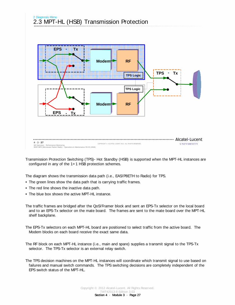
Copyright © 2012 Alcatel-Lucent. All Rights Reserved.TWT42013-8 Edition 3.03
Section 4 · Module 3 · Page 27Section 4 · Module 3 · Page 27
9500 MPR (Microwave Packet Radio) · Operations & Maintenance R3.03 (ANSI)NE Operation · Performance Monitoring4 · 3 · 27
COPYRIGHT © ALCATEL-LUCENT 2012. ALL RIGHTS RESERVED.
2 Diagnosis Menu
2.3 MPT-HL (HSB) Transmission Protection
Modem
Modem
RF
RF
EPS - Tx
Modem RF
EPS - Tx
Modem RF
TPS - TxTPS Logic
TPS Logic
Transmission Protection Switching (TPS)- Hot Standby (HSB) is supported when the MPT-HL instances are configured in any of the 1+1 HSB protection schemes.
The diagram shows the transmission data path (i.e., EAS/P8ETH to Radio) for TPS.
The green lines show the data path that is carrying traffic frames.
The red line shows the inactive data path.
The blue box shows the active MPT-HL instance.
The traffic frames are bridged after the QoS/Framer block and sent an EPS-Tx selector on the local board and to an EPS-Tx selector on the mate board. The frames are sent to the mate board over the MPT-HL shelf backplane.
The EPS-Tx selectors on each MPT-HL board are positioned to select traffic from the active board. The Modem blocks on each board receive the exact same data.
The RF block on each MPT-HL instance (i.e., main and spare) supplies a transmit signal to the TPS-Tx selector. The TPS-Tx selector is an external relay switch.
The TPS decision machines on the MPT-HL instances will coordinate which transmit signal to use based on failures and manual switch commands. The TPS switching decisions are completely independent of the EPS switch status of the MPT-HL.
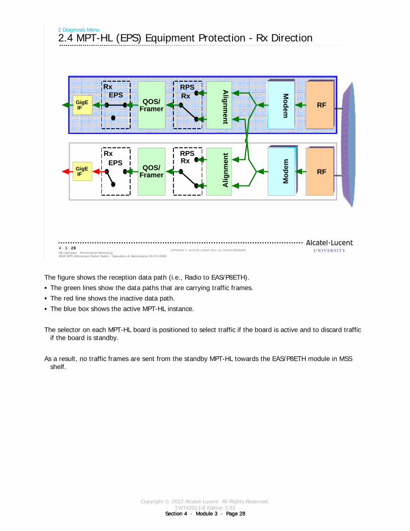
Copyright © 2012 Alcatel-Lucent. All Rights Reserved.TWT42013-8 Edition 3.03
Section 4 · Module 3 · Page 28Section 4 · Module 3 · Page 28
9500 MPR (Microwave Packet Radio) · Operations & Maintenance R3.03 (ANSI)NE Operation · Performance Monitoring4 · 3 · 28
COPYRIGHT © ALCATEL-LUCENT 2012. ALL RIGHTS RESERVED.
2 Diagnosis Menu
2.4 MPT-HL (EPS) Equipment Protection - Rx Direction
Modem
Modem
RF
RF
Modem RFGigE
IF
EPSRx A
lignment
RPSRx
Mod
em
RFGigEIF
EPSRx
Alig
nmen
tRPSRx
QOS/Framer
QOS/Framer
The figure shows the reception data path (i.e., Radio to EAS/P8ETH).
The green lines show the data paths that are carrying traffic frames.
The red line shows the inactive data path.
The blue box shows the active MPT-HL instance.
The selector on each MPT-HL board is positioned to select traffic if the board is active and to discard traffic if the board is standby.
As a result, no traffic frames are sent from the standby MPT-HL towards the EAS/P8ETH module in MSS shelf.
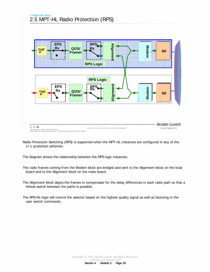
Copyright © 2012 Alcatel-Lucent. All Rights Reserved.TWT42013-8 Edition 3.03
Section 4 · Module 3 · Page 29Section 4 · Module 3 · Page 29
9500 MPR (Microwave Packet Radio) · Operations & Maintenance R3.03 (ANSI)NE Operation · Performance Monitoring4 · 3 · 29
COPYRIGHT © ALCATEL-LUCENT 2012. ALL RIGHTS RESERVED.
2 Diagnosis Menu
2.5 MPT-HL Radio Protection (RPS)
Modem
Modem RF
RF
Modem RF
EPSRx
Alignm
ent
RPSRx
Mod
em
RF
EPSRx
Alig
nmen
t
RPSRx
RPS Logic
RPS Logic
GigEIF
GigEIF
QOS/Framer
QOS/Framer
Radio Protection Switching (RPS) is supported when the MPT-HL instances are configured in any of the 1+1 protection schemes.
The diagram shows the relationship between the RPS logic instances.
The radio frames coming from the Modem block are bridged and sent to the Alignment block on the local board and to the Alignment block on the mate board.
The Alignment block aligns the frames to compensate for the delay differences in each radio path so that a hitless switch between the paths is possible.
The RPS-Rx logic will control the selector based on the highest quality signal as well as factoring in the user switch commands.
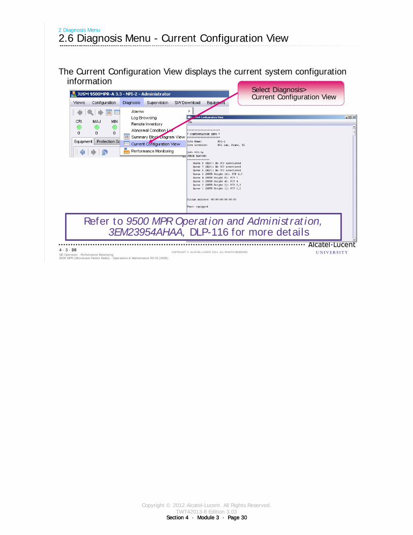
Copyright © 2012 Alcatel-Lucent. All Rights Reserved.TWT42013-8 Edition 3.03
Section 4 · Module 3 · Page 30Section 4 · Module 3 · Page 30
9500 MPR (Microwave Packet Radio) · Operations & Maintenance R3.03 (ANSI)NE Operation · Performance Monitoring4 · 3 · 30
COPYRIGHT © ALCATEL-LUCENT 2012. ALL RIGHTS RESERVED.
The Current Configuration View displays the current system configuration information
2 Diagnosis Menu
2.6 Diagnosis Menu - Current Configuration View
Refer to 9500 MPR Operation and Administration, 3EM23954AHAA, DLP-116 for more details
Select Diagnosis>Current Configuration View
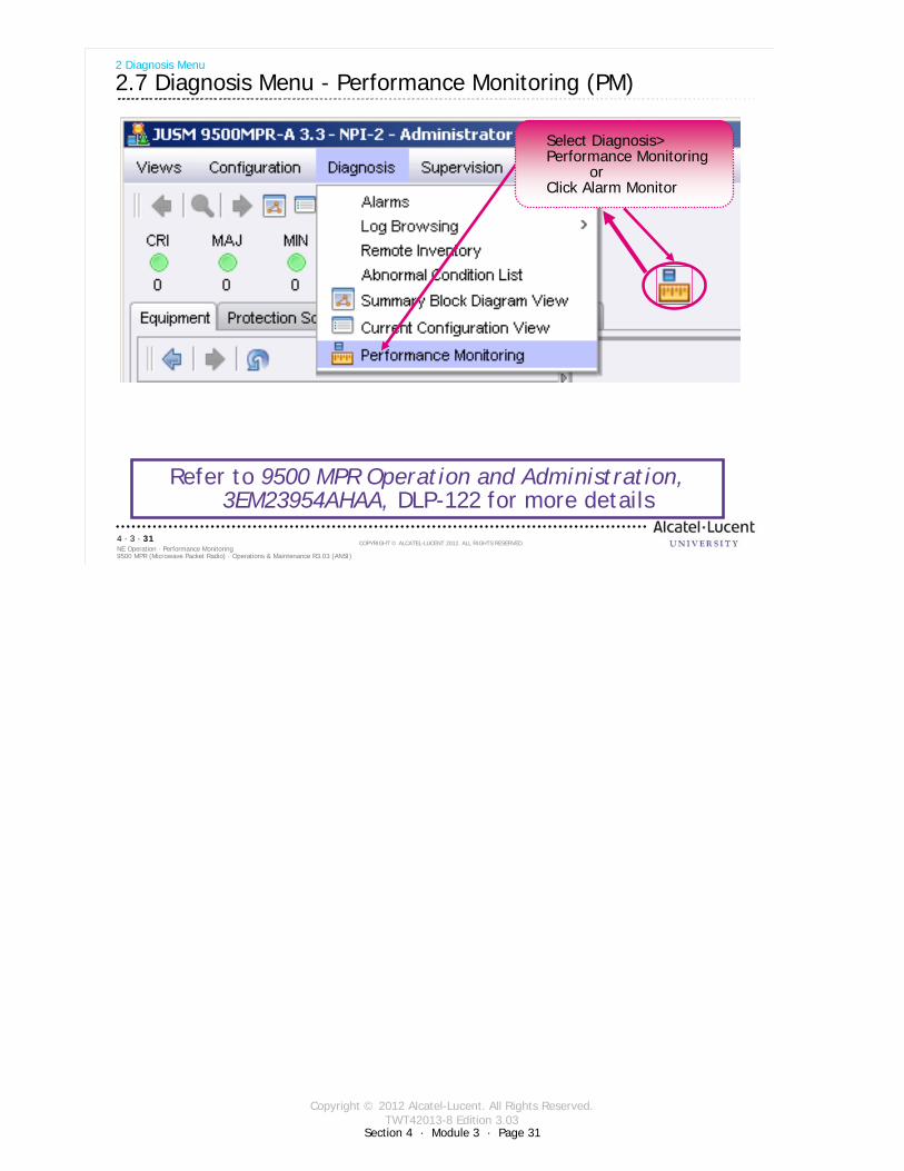
Copyright © 2012 Alcatel-Lucent. All Rights Reserved.TWT42013-8 Edition 3.03
Section 4 · Module 3 · Page 31
9500 MPR (Microwave Packet Radio) · Operations & Maintenance R3.03 (ANSI)NE Operation · Performance Monitoring4 · 3 · 31
COPYRIGHT © ALCATEL-LUCENT 2012. ALL RIGHTS RESERVED.
2 Diagnosis Menu
2.7 Diagnosis Menu - Performance Monitoring (PM)
Refer to 9500 MPR Operation and Administration, 3EM23954AHAA, DLP-122 for more details
Select Diagnosis>Performance Monitoring
orClick Alarm Monitor
Copyright © 2012 Alcatel-Lucent. All Rights Reserved.TWT42013-8 Edition 3.03
Section 4 · Module 3 · Page 32Section 4 · Module 3 · Page 32
9500 MPR (Microwave Packet Radio) · Operations & Maintenance R3.03 (ANSI)NE Operation · Performance Monitoring4 · 3 · 32
COPYRIGHT © ALCATEL-LUCENT 2012. ALL RIGHTS RESERVED.
2 Diagnosis Menu
2.7 Diagnosis Menu - Performance Monitoring (PM) [cont.]
PM provides a QoS indication for the Radio and Link Hop Sections:Radio Hop - Unprotected radio channel (before RPS in 1+1 radio configurations)Link Hop - Protected radio channel (after RPS in 1+1 radio configurations)
Adaptive Modulation PM captures the modulation scheme used on the Tx side when adaptive modulation is enabled. In 1+1 HSB radio configuration, the statistics are associated with the link level after RPS. Not supported in 1+1 FD radio configurations.
Defect second:Radio Hop Section - second in which an LOF or DemFail occursLink Hop Section - second in which an LOF occurs at the link level after RPS
Errored Block:Radio Hop Section - number of errored blocks
Link Hop Section - number of errored block at the link level after RPS
Copyright © 2012 Alcatel-Lucent. All Rights Reserved.TWT42013-8 Edition 3.03
Section 4 · Module 3 · Page 33Section 4 · Module 3 · Page 33
9500 MPR (Microwave Packet Radio) · Operations & Maintenance R3.03 (ANSI)NE Operation · Performance Monitoring4 · 3 · 33
COPYRIGHT © ALCATEL-LUCENT 2012. ALL RIGHTS RESERVED.
2 Diagnosis Menu
2.7 Diagnosis Menu - Performance Monitoring (PM) [cont.]
Four PM counters are supported:Errored Second (ES) - When a defect second is set or if there is at least one or more errored blocks.Severely Errored Seconds (SES) - When a defect second is set and if the errored block count is greater or equal to 30% of the blocks in one second.Background Block Error (BBE) - The number of block errors in a one second period and the second is not an SES.Unavailable Seconds (UAS) - A time period starting after ten consecutive SES events are detected. The qualifying ten consecutive SES seconds are included in the UAS time period. Ending upon the detection of ten consecutive non SES events. These non SES seconds are not included in the UAS time period.
PM data is collected for 15 minute and 24 hour time periods. One current register and 96 history reports are available for 15 minute period. One current register and 8 history reports are available for 24 hour time period.

Copyright © 2012 Alcatel-Lucent. All Rights Reserved.TWT42013-8 Edition 3.03
Section 4 · Module 3 · Page 34Section 4 · Module 3 · Page 34
9500 MPR (Microwave Packet Radio) · Operations & Maintenance R3.03 (ANSI)NE Operation · Performance Monitoring4 · 3 · 34
COPYRIGHT © ALCATEL-LUCENT 2012. ALL RIGHTS RESERVED.
2 Diagnosis Menu
2.8 Performance Monitoring Window
Select Ethernet Statistics
1
Select card to monitor
2
Click PM Status icon
3
Physical Level Management (PLM) is in charge of the complete management of the PM on CSM-E/Core-E monitoring points (radio hop and link):
monitoring activation/deactivationcollection of PM counters values by means of a periodic polling (1 Sec.) on HW componentsstoring of the PM counters value that can be retrieved by Infomodel Level Management (ILM) on requestgeneration and management of history datamanagement of the thresholds configuration used for threshold crossing alarm (TCA) managementThreshold Crossing Alarm (TCA) and Unavailable Time alarms detection and reporting to ILM
The CT/NMS will monitor only the counters related to Ethernet traffic.
TTO (Total Transmitted Octets)TTF (Total Transmitted Frames)TDF (Total Discarded Frames)
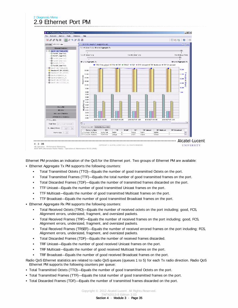
Copyright © 2012 Alcatel-Lucent. All Rights Reserved.TWT42013-8 Edition 3.03
Section 4 · Module 3 · Page 35Section 4 · Module 3 · Page 35
9500 MPR (Microwave Packet Radio) · Operations & Maintenance R3.03 (ANSI)NE Operation · Performance Monitoring4 · 3 · 35
COPYRIGHT © ALCATEL-LUCENT 2012. ALL RIGHTS RESERVED.
2 Diagnosis Menu
2.9 Ethernet Port PM
Ethernet PM provides an indication of the QoS for the Ethernet port. Two groups of Ethernet PM are available:
Ethernet Aggregate Tx PM supports the following counters:
Total Transmitted Octets (TTO)—Equals the number of good transmitted Octets on the port.
Total Transmitted Frames (TTF)—Equals the total number of good transmitted frames on the port.
Total Discarded Frames (TDF)—Equals the number of transmitted frames discarded on the port.
TTF Unicast—Equals the number of good transmitted Unicast frames on the port.
TTF Multicast—Equals the number of good transmitted Multicast frames on the port.
TTF Broadcast—Equals the number of good transmitted Broadcast frames on the port.
Ethernet Aggregate Rx PM supports the following counters:
Total Received Octets (TRO)—Equals the number of received octets on the port including; good, FCS, Alignment errors, undersized, fragment, and oversized packets.
Total Received Frames (TRF)—Equals the number of received frames on the port including; good, FCS, Alignment errors, undersized, fragment, and oversized packets.
Total Received Frames (TRSEF)—Equals the number of received errored frames on the port including; FCS, Alignment errors, undersized, fragment, and oversized packets.
Total Discarded Frames (TDF)—Equals the number of received frames discarded.
TRF Unicast—Equals the number of good received Unicast frames on the port.
TRF Multicast—Equals the number of good received Multicast frames on the port.
TRF Broadcast—Equals the number of good received Broadcast frames on the port.
Radio QoS Ethernet statistics are related to radio QoS queues (queues 1 to 5) for each Tx radio direction. Radio QoS Ethernet PM supports the following counters per queue:
Total Transmitted Octets (TTO)—Equals the number of good transmitted Octets on the port.
Total Transmitted Frames (TTF)—Equals the total number of good transmitted frames on the port.
Total Discarded Frames (TDF)—Equals the number of transmitted frames discarded on the port.
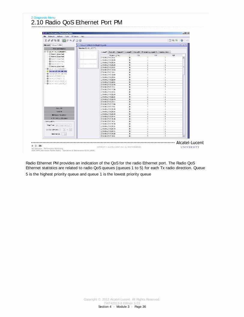
Copyright © 2012 Alcatel-Lucent. All Rights Reserved.TWT42013-8 Edition 3.03
Section 4 · Module 3 · Page 36
9500 MPR (Microwave Packet Radio) · Operations & Maintenance R3.03 (ANSI)NE Operation · Performance Monitoring4 · 3 · 36
COPYRIGHT © ALCATEL-LUCENT 2012. ALL RIGHTS RESERVED.
2 Diagnosis Menu
2.10 Radio QoS Ethernet Port PM
Radio Ethernet PM provides an indication of the QoS for the radio Ethernet port. The Radio QoS Ethernet statistics are related to radio QoS queues (queues 1 to 5) for each Tx radio direction. Queue
5 is the highest priority queue and queue 1 is the lowest priority queue
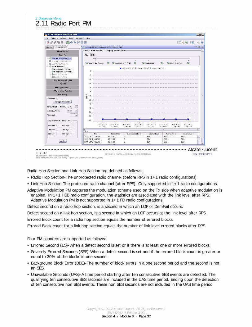
Copyright © 2012 Alcatel-Lucent. All Rights Reserved.TWT42013-8 Edition 3.03
Section 4 · Module 3 · Page 37Section 4 · Module 3 · Page 37
9500 MPR (Microwave Packet Radio) · Operations & Maintenance R3.03 (ANSI)NE Operation · Performance Monitoring4 · 3 · 37
COPYRIGHT © ALCATEL-LUCENT 2012. ALL RIGHTS RESERVED.
2 Diagnosis Menu
2.11 Radio Port PM
Radio Hop Section and Link Hop Section are defined as follows:
Radio Hop Section-The unprotected radio channel (before RPS in 1+1 radio configurations)
Link Hop Section-The protected radio channel (after RPS); Only supported in 1+1 radio configurations.
Adaptive Modulation PM captures the modulation scheme used on the Tx side when adaptive modulation is enabled. In 1+1 HSB radio configuration, the statistics are associated with the link level after RPS. Adaptive Modulation PM is not supported in 1+1 FD radio configurations.
Defect second on a radio hop section, is a second in which an LOF or DemFail occurs.
Defect second on a link hop section, is a second in which an LOF occurs at the link level after RPS.
Errored Block count for a radio hop section equals the number of errored blocks.
Errored Block count for a link hop section equals the number of link level errored blocks after RPS.
Four PM counters are supported as follows:
Errored Second (ES)-When a defect second is set or if there is at least one or more errored blocks.
Severely Errored Seconds (SES)-When a defect second is set and if the errored block count is greater or equal to 30% of the blocks in one second.
Background Block Error (BBE)-The number of block errors in a one second period and the second is not an SES.
Unavailable Seconds (UAS)-A time period starting after ten consecutive SES events are detected. The qualifying ten consecutive SES seconds are included in the UAS time period. Ending upon the detection of ten consecutive non SES events. These non SES seconds are not included in the UAS time period.
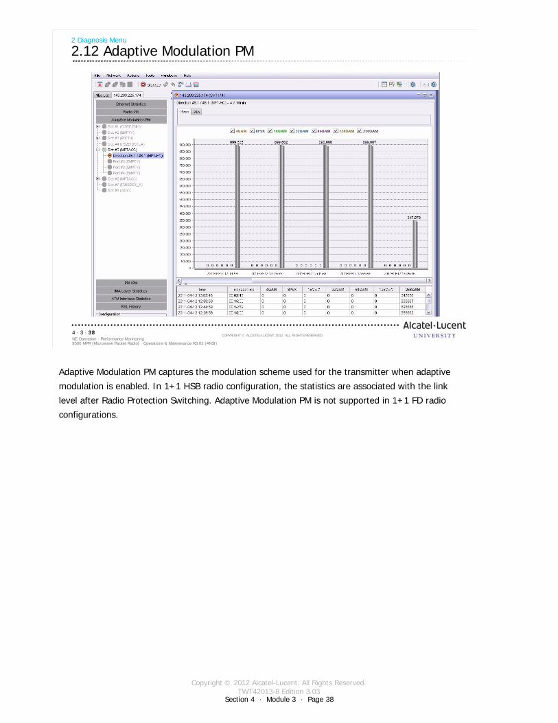
Copyright © 2012 Alcatel-Lucent. All Rights Reserved.TWT42013-8 Edition 3.03
Section 4 · Module 3 · Page 38
9500 MPR (Microwave Packet Radio) · Operations & Maintenance R3.03 (ANSI)NE Operation · Performance Monitoring4 · 3 · 38
COPYRIGHT © ALCATEL-LUCENT 2012. ALL RIGHTS RESERVED.
2 Diagnosis Menu
2.12 Adaptive Modulation PM
Adaptive Modulation PM captures the modulation scheme used for the transmitter when adaptive
modulation is enabled. In 1+1 HSB radio configuration, the statistics are associated with the link
level after Radio Protection Switching. Adaptive Modulation PM is not supported in 1+1 FD radio
configurations.
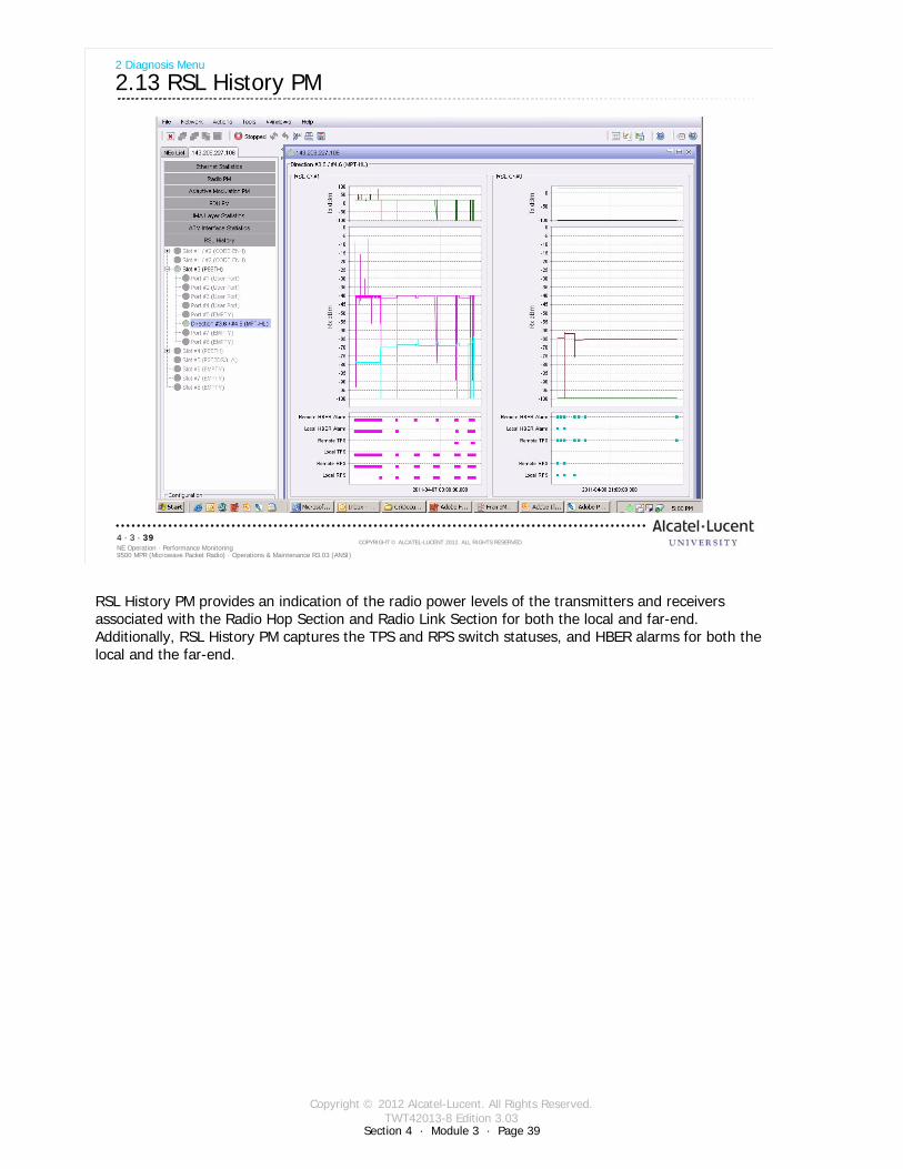
Copyright © 2012 Alcatel-Lucent. All Rights Reserved.TWT42013-8 Edition 3.03
Section 4 · Module 3 · Page 39
9500 MPR (Microwave Packet Radio) · Operations & Maintenance R3.03 (ANSI)NE Operation · Performance Monitoring4 · 3 · 39
COPYRIGHT © ALCATEL-LUCENT 2012. ALL RIGHTS RESERVED.
2 Diagnosis Menu
2.13 RSL History PM
RSL History PM provides an indication of the radio power levels of the transmitters and receivers associated with the Radio Hop Section and Radio Link Section for both the local and far-end. Additionally, RSL History PM captures the TPS and RPS switch statuses, and HBER alarms for both the local and the far-end.

Copyright © 2012 Alcatel-Lucent. All Rights Reserved.TWT42013-8 Edition 3.03
Section 4 · Module 3 · Page 40
9500 MPR (Microwave Packet Radio) · Operations & Maintenance R3.03 (ANSI)NE Operation · Performance Monitoring4 · 3 · 40
COPYRIGHT © ALCATEL-LUCENT 2012. ALL RIGHTS RESERVED.
Blank page
This page is left blank intentionally

Copyright © 2012 Alcatel-Lucent. All Rights Reserved.TWT42013-8 Edition 3.03
Section 4 · Module 3 · Page 41
9500 MPR (Microwave Packet Radio) · Operations & Maintenance R3.03 (ANSI)NE Operation · Performance Monitoring4 · 3 · 41
COPYRIGHT © ALCATEL-LUCENT 2012. ALL RIGHTS RESERVED.
3 Loopback
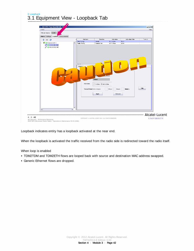
Copyright © 2012 Alcatel-Lucent. All Rights Reserved.TWT42013-8 Edition 3.03
Section 4 · Module 3 · Page 42Section 4 · Module 3 · Page 42
9500 MPR (Microwave Packet Radio) · Operations & Maintenance R3.03 (ANSI)NE Operation · Performance Monitoring4 · 3 · 42
COPYRIGHT © ALCATEL-LUCENT 2012. ALL RIGHTS RESERVED.
3 Loopback
3.1 Equipment View - Loopback Tab
Loopback indicates entity has a loopback activated at the near end.
When the loopback is activated the traffic received from the radio side is redirected toward the radio itself.
When loop is enabled
TDM2TDM and TDM2ETH flows are looped back with source and destination MAC address swapped.
Generic Ethernet flows are dropped.

Copyright © 2012 Alcatel-Lucent. All Rights Reserved.TWT42013-8 Edition 3.03
Section 4 · Module 3 · Page 43
9500 MPR (Microwave Packet Radio) · Operations & Maintenance R3.03 (ANSI)NE Operation · Performance Monitoring4 · 3 · 43
COPYRIGHT © ALCATEL-LUCENT 2012. ALL RIGHTS RESERVED.
4 MOD300 IF Cable Loopback
Refer to 9500 MPR Operation and Administration, 3EM23954AHAA, DLP-130 for more details
Copyright © 2012 Alcatel-Lucent. All Rights Reserved.TWT42013-8 Edition 3.03
Section 4 · Module 3 · Page 44Section 4 · Module 3 · Page 44
9500 MPR (Microwave Packet Radio) · Operations & Maintenance R3.03 (ANSI)NE Operation · Performance Monitoring4 · 3 · 44
COPYRIGHT © ALCATEL-LUCENT 2012. ALL RIGHTS RESERVED.
4 MOD300 IF Cable Loopback
4.1 MOD300 IF Cable Loopback
IF cable loopback is active only on the cross-connections associated with TDM2TDM and TDM2Eth profiles. Loopback of Ethernet traffic is not supported.
Can be activated from the local NE only
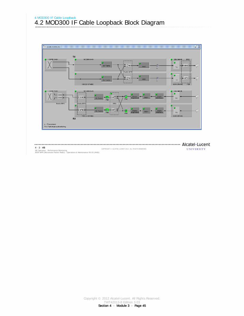
Copyright © 2012 Alcatel-Lucent. All Rights Reserved.TWT42013-8 Edition 3.03
Section 4 · Module 3 · Page 45Section 4 · Module 3 · Page 45
9500 MPR (Microwave Packet Radio) · Operations & Maintenance R3.03 (ANSI)NE Operation · Performance Monitoring4 · 3 · 45
COPYRIGHT © ALCATEL-LUCENT 2012. ALL RIGHTS RESERVED.
4 MOD300 IF Cable Loopback
4.2 MOD300 IF Cable Loopback Block Diagram
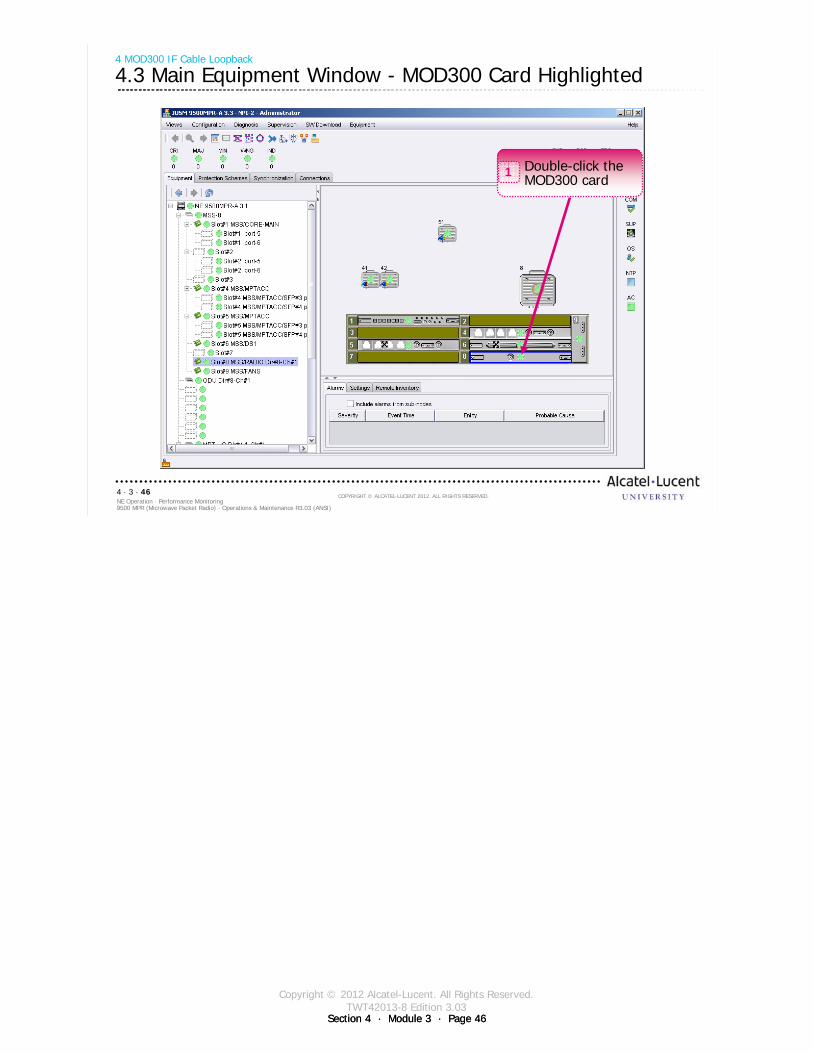
Copyright © 2012 Alcatel-Lucent. All Rights Reserved.TWT42013-8 Edition 3.03
Section 4 · Module 3 · Page 46Section 4 · Module 3 · Page 46
9500 MPR (Microwave Packet Radio) · Operations & Maintenance R3.03 (ANSI)NE Operation · Performance Monitoring4 · 3 · 46
COPYRIGHT © ALCATEL-LUCENT 2012. ALL RIGHTS RESERVED.
4 MOD300 IF Cable Loopback
4.3 Main Equipment Window - MOD300 Card Highlighted
Double-click the MOD300 card
1
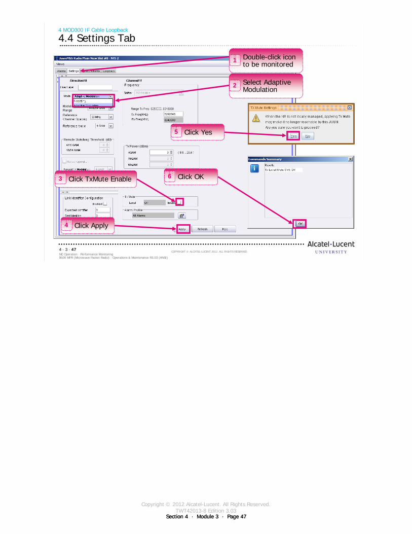
Copyright © 2012 Alcatel-Lucent. All Rights Reserved.TWT42013-8 Edition 3.03
Section 4 · Module 3 · Page 47Section 4 · Module 3 · Page 47
9500 MPR (Microwave Packet Radio) · Operations & Maintenance R3.03 (ANSI)NE Operation · Performance Monitoring4 · 3 · 47
COPYRIGHT © ALCATEL-LUCENT 2012. ALL RIGHTS RESERVED.
4 MOD300 IF Cable Loopback
4.4 Settings Tab
Double-click icon to be monitored
1
Select Adaptive Modulation
2
Click TxMute Enable3
Click Apply4
Click Yes5
Click OK6
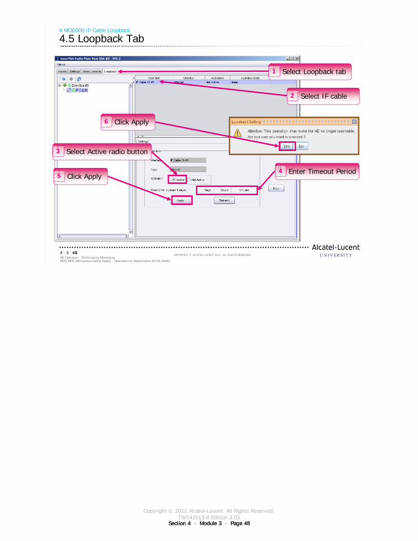
Copyright © 2012 Alcatel-Lucent. All Rights Reserved.TWT42013-8 Edition 3.03
Section 4 · Module 3 · Page 48Section 4 · Module 3 · Page 48
9500 MPR (Microwave Packet Radio) · Operations & Maintenance R3.03 (ANSI)NE Operation · Performance Monitoring4 · 3 · 48
COPYRIGHT © ALCATEL-LUCENT 2012. ALL RIGHTS RESERVED.
4 MOD300 IF Cable Loopback
4.5 Loopback Tab
Select Loopback tab1
Enter Timeout Period4
Select IF cable2
Select Active radio button3
Click Apply5
Click Apply6

Copyright © 2012 Alcatel-Lucent. All Rights Reserved.TWT42013-8 Edition 3.03
Section 4 · Module 3 · Page 49
9500 MPR (Microwave Packet Radio) · Operations & Maintenance R3.03 (ANSI)NE Operation · Performance Monitoring4 · 3 · 49
COPYRIGHT © ALCATEL-LUCENT 2012. ALL RIGHTS RESERVED.
5 Core Facing PDH Tributary Loopback
Refer to 9500 MPR Operation and Administration, 3EM23954AHAA, DLP-133 for more details
Copyright © 2012 Alcatel-Lucent. All Rights Reserved.TWT42013-8 Edition 3.03
Section 4 · Module 3 · Page 50Section 4 · Module 3 · Page 50
9500 MPR (Microwave Packet Radio) · Operations & Maintenance R3.03 (ANSI)NE Operation · Performance Monitoring4 · 3 · 50
COPYRIGHT © ALCATEL-LUCENT 2012. ALL RIGHTS RESERVED.
5 Core Facing PDH Tributary Loopback
5.1 Core Facing PDH Tributary Loopback
Core Facing PDH Tributary Loopback uses the signal from the CSM-E/Core-E switch matrix to be transmitted by the PDH transponder card and replaces the signal received by the PDH transponder and sends the signal back to the CSM-E/Core-E switch matrix
Core Facing PDH Tributary Loopback is a drop-and-continue internalloopback
Core Facing PDH Tributary Loopback can be activated on a per tributary basis independent of the other PDH tributaries.
Core Facing PDH Tributary Loopback is supported on DS1 and DS3 tributaries
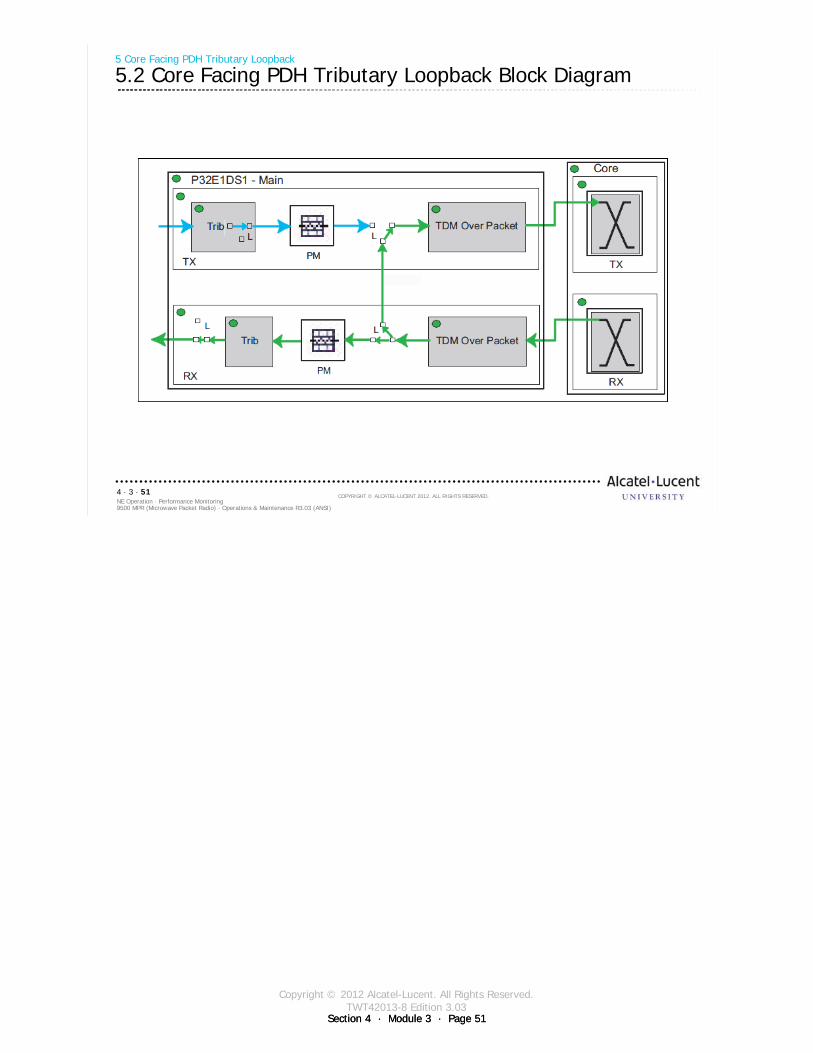
Copyright © 2012 Alcatel-Lucent. All Rights Reserved.TWT42013-8 Edition 3.03
Section 4 · Module 3 · Page 51Section 4 · Module 3 · Page 51
9500 MPR (Microwave Packet Radio) · Operations & Maintenance R3.03 (ANSI)NE Operation · Performance Monitoring4 · 3 · 51
COPYRIGHT © ALCATEL-LUCENT 2012. ALL RIGHTS RESERVED.
5 Core Facing PDH Tributary Loopback
5.2 Core Facing PDH Tributary Loopback Block Diagram
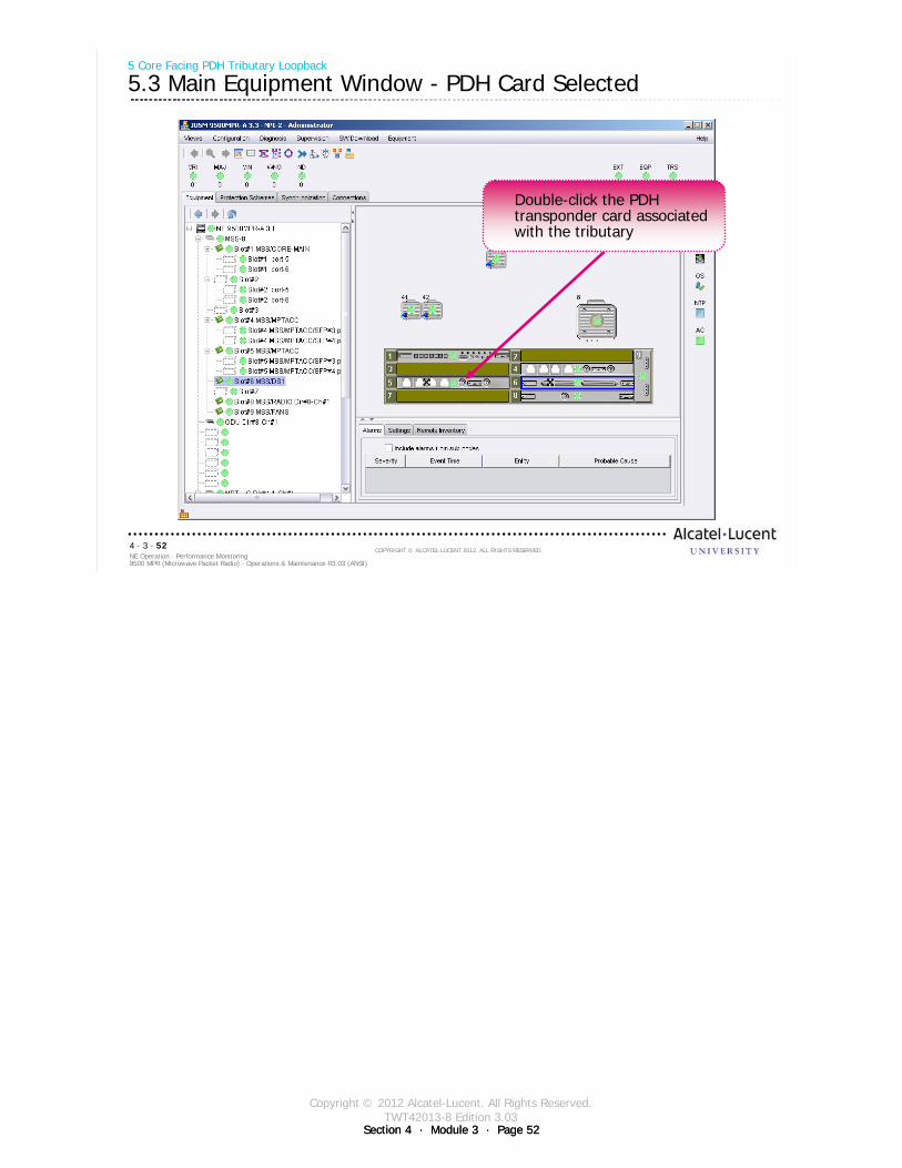
Copyright © 2012 Alcatel-Lucent. All Rights Reserved.TWT42013-8 Edition 3.03
Section 4 · Module 3 · Page 52Section 4 · Module 3 · Page 52
9500 MPR (Microwave Packet Radio) · Operations & Maintenance R3.03 (ANSI)NE Operation · Performance Monitoring4 · 3 · 52
COPYRIGHT © ALCATEL-LUCENT 2012. ALL RIGHTS RESERVED.
5 Core Facing PDH Tributary Loopback
5.3 Main Equipment Window - PDH Card Selected
Double-click the PDH transponder card associated with the tributary
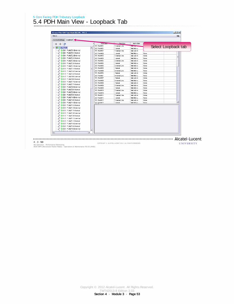
Copyright © 2012 Alcatel-Lucent. All Rights Reserved.TWT42013-8 Edition 3.03
Section 4 · Module 3 · Page 53Section 4 · Module 3 · Page 53
9500 MPR (Microwave Packet Radio) · Operations & Maintenance R3.03 (ANSI)NE Operation · Performance Monitoring4 · 3 · 53
COPYRIGHT © ALCATEL-LUCENT 2012. ALL RIGHTS RESERVED.
5 Core Facing PDH Tributary Loopback
5.4 PDH Main View - Loopback Tab
Select Loopback tab
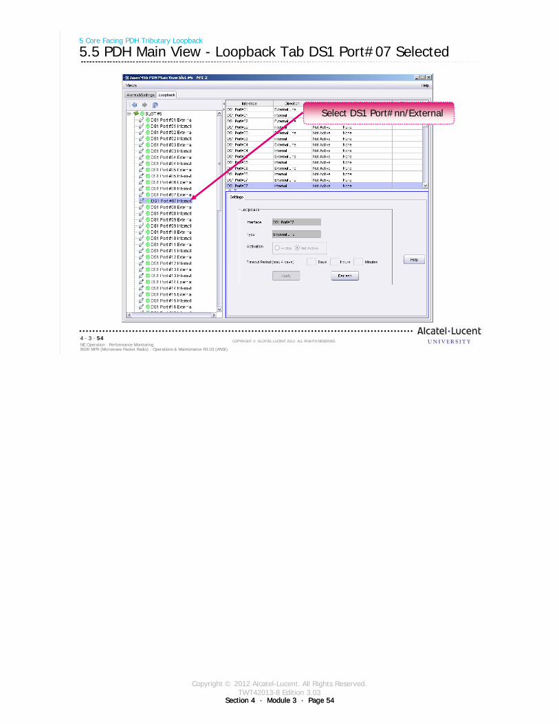
Copyright © 2012 Alcatel-Lucent. All Rights Reserved.TWT42013-8 Edition 3.03
Section 4 · Module 3 · Page 54Section 4 · Module 3 · Page 54
9500 MPR (Microwave Packet Radio) · Operations & Maintenance R3.03 (ANSI)NE Operation · Performance Monitoring4 · 3 · 54
COPYRIGHT © ALCATEL-LUCENT 2012. ALL RIGHTS RESERVED.
5 Core Facing PDH Tributary Loopback
5.5 PDH Main View - Loopback Tab DS1 Port#07 Selected
Select DS1 Port#nn/External
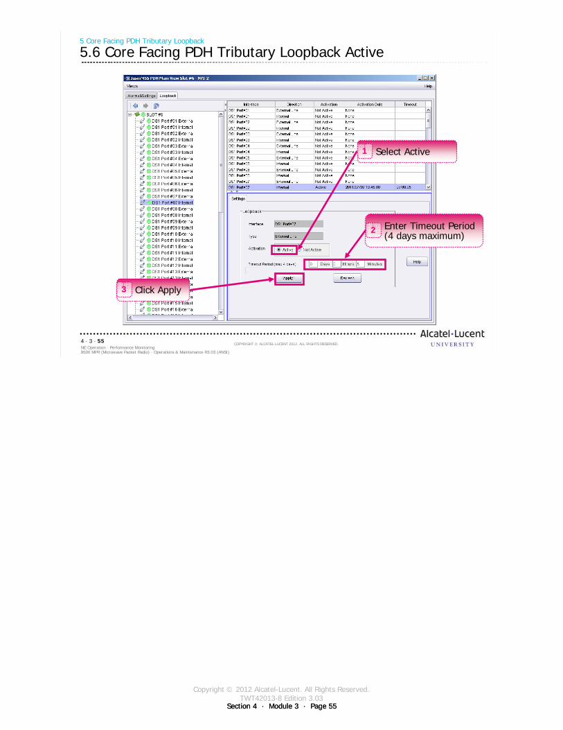
Copyright © 2012 Alcatel-Lucent. All Rights Reserved.TWT42013-8 Edition 3.03
Section 4 · Module 3 · Page 55Section 4 · Module 3 · Page 55
9500 MPR (Microwave Packet Radio) · Operations & Maintenance R3.03 (ANSI)NE Operation · Performance Monitoring4 · 3 · 55
COPYRIGHT © ALCATEL-LUCENT 2012. ALL RIGHTS RESERVED.
5 Core Facing PDH Tributary Loopback
5.6 Core Facing PDH Tributary Loopback Active
Select Active1
Click Apply3
Enter Timeout Period (4 days maximum)
2

Copyright © 2012 Alcatel-Lucent. All Rights Reserved.TWT42013-8 Edition 3.03
Section 4 · Module 3 · Page 56Section 4 · Module 3 · Page 56
9500 MPR (Microwave Packet Radio) · Operations & Maintenance R3.03 (ANSI)NE Operation · Performance Monitoring4 · 3 · 56
COPYRIGHT © ALCATEL-LUCENT 2012. ALL RIGHTS RESERVED.
Blank page
Switch to notes view!
This page intentionally left blank

Copyright © 2012 Alcatel-Lucent. All Rights Reserved.TWT42013-8 Edition 3.03
Section 4 · Module 3 · Page 57
9500 MPR (Microwave Packet Radio) · Operations & Maintenance R3.03 (ANSI)NE Operation · Performance Monitoring4 · 3 · 57
COPYRIGHT © ALCATEL-LUCENT 2012. ALL RIGHTS RESERVED.
6 Line Facing PDH Tributary Loopback
Refer to 9500 MPR Operation and Administration, 3EM23954AHAA, DLP-134 for more details
Copyright © 2012 Alcatel-Lucent. All Rights Reserved.TWT42013-8 Edition 3.03
Section 4 · Module 3 · Page 58Section 4 · Module 3 · Page 58
9500 MPR (Microwave Packet Radio) · Operations & Maintenance R3.03 (ANSI)NE Operation · Performance Monitoring4 · 3 · 58
COPYRIGHT © ALCATEL-LUCENT 2012. ALL RIGHTS RESERVED.
6 Line Facing PDH Tributary Loopback
6.1 Line Facing PDH Tributary Loopback
Line Facing PDH Tributary Loopback mode uses the received line tributary input signal to the PDH transponder card and sends the signal back to the transmit line tributary output signal
Line Facing PDH Tributary Loopback is a drop-and-continue line externalloopback
Line Facing PDH Tributary Loopback can be activated on a per tributary basis independent of the other PDH tributaries.
Core Facing PDH Tributary Loopback is only supported on DS1 tributaries (P32E1DS1 card)
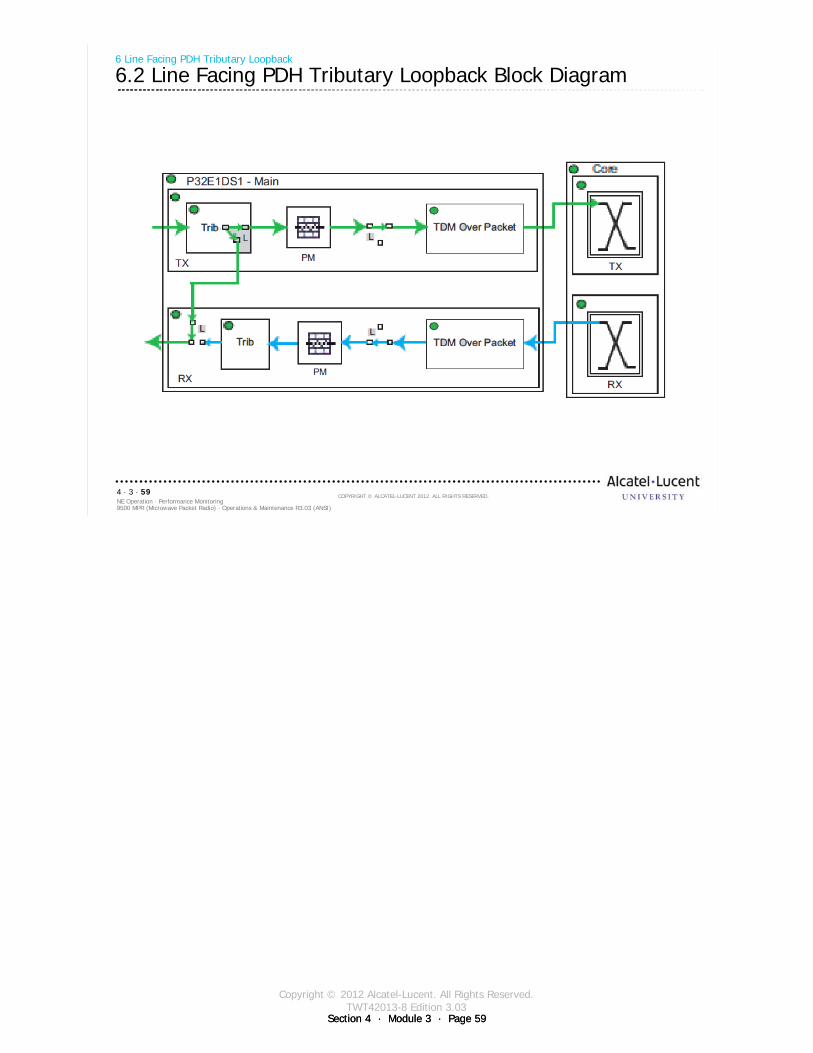
Copyright © 2012 Alcatel-Lucent. All Rights Reserved.TWT42013-8 Edition 3.03
Section 4 · Module 3 · Page 59Section 4 · Module 3 · Page 59
9500 MPR (Microwave Packet Radio) · Operations & Maintenance R3.03 (ANSI)NE Operation · Performance Monitoring4 · 3 · 59
COPYRIGHT © ALCATEL-LUCENT 2012. ALL RIGHTS RESERVED.
6 Line Facing PDH Tributary Loopback
6.2 Line Facing PDH Tributary Loopback Block Diagram
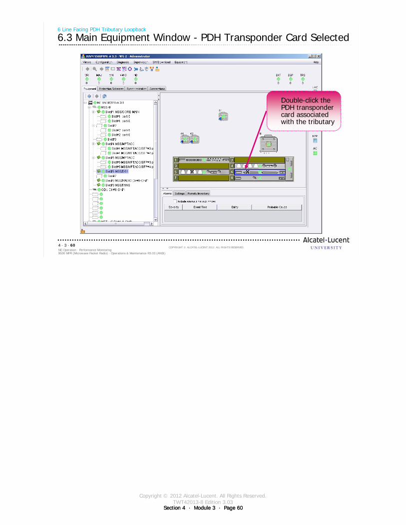
Copyright © 2012 Alcatel-Lucent. All Rights Reserved.TWT42013-8 Edition 3.03
Section 4 · Module 3 · Page 60Section 4 · Module 3 · Page 60
9500 MPR (Microwave Packet Radio) · Operations & Maintenance R3.03 (ANSI)NE Operation · Performance Monitoring4 · 3 · 60
COPYRIGHT © ALCATEL-LUCENT 2012. ALL RIGHTS RESERVED.
6 Line Facing PDH Tributary Loopback
6.3 Main Equipment Window - PDH Transponder Card Selected
Double-click the PDH transponder card associated with the tributary
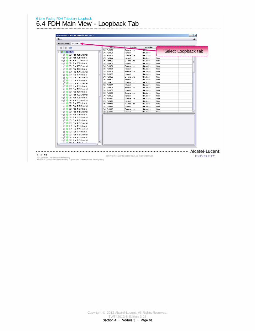
Copyright © 2012 Alcatel-Lucent. All Rights Reserved.TWT42013-8 Edition 3.03
Section 4 · Module 3 · Page 61Section 4 · Module 3 · Page 61
9500 MPR (Microwave Packet Radio) · Operations & Maintenance R3.03 (ANSI)NE Operation · Performance Monitoring4 · 3 · 61
COPYRIGHT © ALCATEL-LUCENT 2012. ALL RIGHTS RESERVED.
6 Line Facing PDH Tributary Loopback
6.4 PDH Main View - Loopback Tab
Select Loopback tab
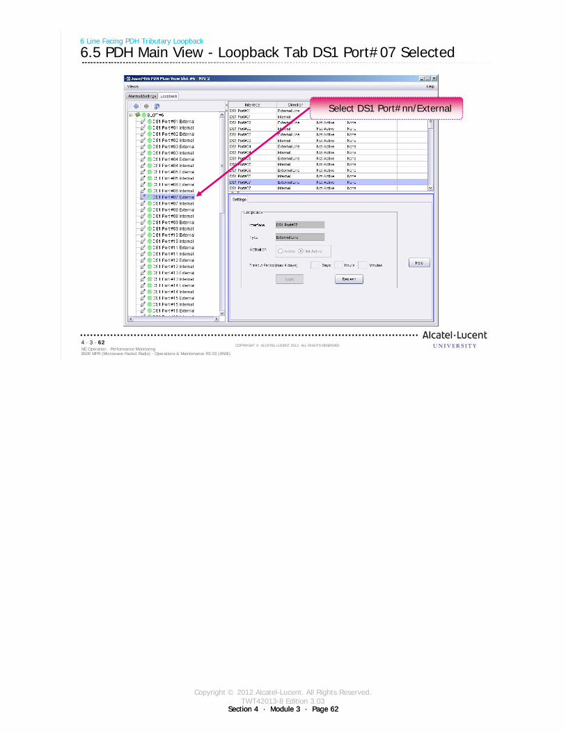
Copyright © 2012 Alcatel-Lucent. All Rights Reserved.TWT42013-8 Edition 3.03
Section 4 · Module 3 · Page 62Section 4 · Module 3 · Page 62
9500 MPR (Microwave Packet Radio) · Operations & Maintenance R3.03 (ANSI)NE Operation · Performance Monitoring4 · 3 · 62
COPYRIGHT © ALCATEL-LUCENT 2012. ALL RIGHTS RESERVED.
6 Line Facing PDH Tributary Loopback
6.5 PDH Main View - Loopback Tab DS1 Port#07 Selected
Select DS1 Port#nn/External

Copyright © 2012 Alcatel-Lucent. All Rights Reserved.TWT42013-8 Edition 3.03
Section 4 · Module 3 · Page 63Section 4 · Module 3 · Page 63
9500 MPR (Microwave Packet Radio) · Operations & Maintenance R3.03 (ANSI)NE Operation · Performance Monitoring4 · 3 · 63
COPYRIGHT © ALCATEL-LUCENT 2012. ALL RIGHTS RESERVED.
6 Line Facing PDH Tributary Loopback
6.6 Line Facing PDH Tributary Loopback Active
Select Active1
Click Apply3
Enter Timeout Period (4 days maximum)
2

Copyright © 2012 Alcatel-Lucent. All Rights Reserved.TWT42013-8 Edition 3.03
Section 4 · Module 3 · Page 64Section 4 · Module 3 · Page 64
9500 MPR (Microwave Packet Radio) · Operations & Maintenance R3.03 (ANSI)NE Operation · Performance Monitoring4 · 3 · 64
COPYRIGHT © ALCATEL-LUCENT 2012. ALL RIGHTS RESERVED.
Blank page
This page intentionally left blank

Copyright © 2012 Alcatel-Lucent. All Rights Reserved.TWT42013-8 Edition 3.03
Section 4 · Module 3 · Page 65
9500 MPR (Microwave Packet Radio) · Operations & Maintenance R3.03 (ANSI)NE Operation · Performance Monitoring4 · 3 · 65
COPYRIGHT © ALCATEL-LUCENT 2012. ALL RIGHTS RESERVED.
7 Radio Facing Circuit Loopback
Refer to 9500 MPR Operation and Administration, 3EM23954AHAA, DLP-143 for more details
Copyright © 2012 Alcatel-Lucent. All Rights Reserved.TWT42013-8 Edition 3.03
Section 4 · Module 3 · Page 66Section 4 · Module 3 · Page 66
9500 MPR (Microwave Packet Radio) · Operations & Maintenance R3.03 (ANSI)NE Operation · Performance Monitoring4 · 3 · 66
COPYRIGHT © ALCATEL-LUCENT 2012. ALL RIGHTS RESERVED.
7 Radio Facing Circuit Loopback
7.1 Radio Facing Circuit Loopback
Radio Facing Circuit Loopback mode is an internal loopback that uses the receive data interface signal on the MPT-HC Transceiver and replaces the signal to be transmitted by the MPT-HC Transceiver and sends the receive signal back to the far-end MPT-HC Transceiver.
Only possible to enable on the aggregate trafficLoop and continue processMPT-HC Transceiver transmit traffic will be droppedWhen this loopback is activated the expected behavior is as follows:
TDM2TDM and TDM2ETH flows are forwarded back to Core card with source and destination MAC addresses swapped.
For TDM2ETH flows, where the ECID Tx and ECID Rx are the same value, the loopback works.For TDM2ETH flows, where the ECID Tx is different form ECID Rx, the loopback fails.
Generic Ethernet flows are dropped.

Copyright © 2012 Alcatel-Lucent. All Rights Reserved.TWT42013-8 Edition 3.03
Section 4 · Module 3 · Page 67Section 4 · Module 3 · Page 67
9500 MPR (Microwave Packet Radio) · Operations & Maintenance R3.03 (ANSI)NE Operation · Performance Monitoring4 · 3 · 67
COPYRIGHT © ALCATEL-LUCENT 2012. ALL RIGHTS RESERVED.
7 Radio Facing Circuit Loopback
7.2 Main Equipment Window - MPT-HC Selected
Double-click the MPT-HC to be monitored
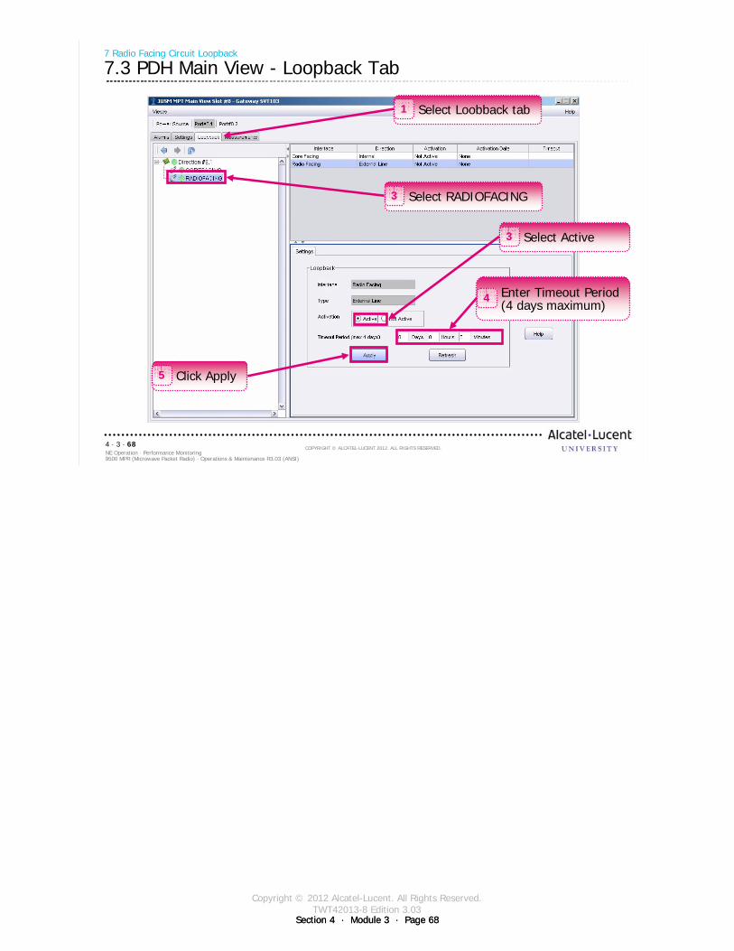
Copyright © 2012 Alcatel-Lucent. All Rights Reserved.TWT42013-8 Edition 3.03
Section 4 · Module 3 · Page 68Section 4 · Module 3 · Page 68
9500 MPR (Microwave Packet Radio) · Operations & Maintenance R3.03 (ANSI)NE Operation · Performance Monitoring4 · 3 · 68
COPYRIGHT © ALCATEL-LUCENT 2012. ALL RIGHTS RESERVED.
7 Radio Facing Circuit Loopback
7.3 PDH Main View - Loopback Tab
Select Active3
Click Apply5
Enter Timeout Period (4 days maximum)
4
Select Loobback tab1
Select RADIOFACING3
Copyright © 2012 Alcatel-Lucent. All Rights Reserved.TWT42013-8 Edition 3.03
Section 4 · Module 3 · Page 69Section 4 · Module 3 · Page 69
9500 MPR (Microwave Packet Radio) · Operations & Maintenance R3.03 (ANSI)NE Operation · Performance Monitoring4 · 3 · 69
COPYRIGHT © ALCATEL-LUCENT 2012. ALL RIGHTS RESERVED.
Module summary
Power MeasurementsAlarmsEvent LogRemote InventoryAbnormal Condition ListSummary Block Diagram ViewCurrent Configuration ViewPerformance Monitoring IconLoopback

Copyright © 2012 Alcatel-Lucent. All Rights Reserved.TWT42013-8 Edition 3.03
Section 4 · Module 3 · Page 70Section 4 · Module 3 · Page 70
9500 MPR (Microwave Packet Radio) · Operations & Maintenance R3.03 (ANSI)NE Operation · Performance Monitoring4 · 3 · 70
COPYRIGHT © ALCATEL-LUCENT 2012. ALL RIGHTS RESERVED.
End of modulePerformance Monitoring
Section 4 · Module 4 · Page 1
Copyright © 2012 Alcatel-Lucent. All Rights Reserved.TWT42013-9 Edition 3.03
Do not delete this graphic elements in here:
All Rights Reserved © Alcatel-Lucent 2012
Module 4Alarm MonitorTWT42013-9 Edition 3.03
Section 4NE Operation
9500 MPR (Microwave Packet Radio)Operations & Maintenance R3.03 (ANSI)
TWT42013 Edition 1.1

Section 4 · Module 4 · Page 2
Copyright © 2012 Alcatel-Lucent. All Rights Reserved.TWT42013-9 Edition 3.03
9500 MPR (Microwave Packet Radio) · Operations & Maintenance R3.03 (ANSI)NE Operation · Alarm Monitor4 · 4 · 2
COPYRIGHT © ALCATEL-LUCENT 2012. ALL RIGHTS RESERVED.
Blank page
This page is left blank intentionallyDocument History
Edition Date Author Remarks
01 2009-07-27 Robinson, Ken First edition
2.01 2010-07-30 Moehlenkamp, John Revised to release 2.01
2.02 2010-11-30 Moehlenkamp, John Revised to release 2.02
3.0 2011-02-28 Moehlenkamp, John Revised to release 3.0
3.01 2011-06-29 Moehlenkamp, John Revised to release 3.01
3.02 2011-11-15 Moehlenkamp, John Updated format and revised to release 3.02
3.03 2012-02-07 Moehlenkamp, John Revised to release 3.03
Section 4 · Module 4 · Page 3
Copyright © 2012 Alcatel-Lucent. All Rights Reserved.TWT42013-9 Edition 3.03
9500 MPR (Microwave Packet Radio) · Operations & Maintenance R3.03 (ANSI)NE Operation · Alarm Monitor4 · 4 · 3
COPYRIGHT © ALCATEL-LUCENT 2012. ALL RIGHTS RESERVED.
Module objectives
Upon completion of this module, you should be able to:
Recognize the meaning of Status and Alarm LEDsFind MPT-HL alarm display using Equipment MenuFind alarm display using Diagnosis MenuFind alarm display using Alarm MonitorList some causes of MPT-HL alarmsList details of an alarmDescribe MPT-HL Receive Signal Level (RSL) history

Section 4 · Module 4 · Page 4
Copyright © 2012 Alcatel-Lucent. All Rights Reserved.TWT42013-9 Edition 3.03
9500 MPR (Microwave Packet Radio) · Operations & Maintenance R3.03 (ANSI)NE Operation · Alarm Monitor4 · 4 · 4
COPYRIGHT © ALCATEL-LUCENT 2012. ALL RIGHTS RESERVED.
Module objectives [cont.]
This page is left blank intentionally
Section 4 · Module 4 · Page 5
Copyright © 2012 Alcatel-Lucent. All Rights Reserved.TWT42013-9 Edition 3.03
9500 MPR (Microwave Packet Radio) · Operations & Maintenance R3.03 (ANSI)NE Operation · Alarm Monitor4 · 4 · 5
COPYRIGHT © ALCATEL-LUCENT 2012. ALL RIGHTS RESERVED.
Table of Contents
Switch to notes view! Page
1 Alarm LEDs 71.1 CSM-E/Core-E Card 81.2 EAS/P8ETH Card 91.3 MPTACC Card 101.4 MOD300 111.5 AUX Card 121.6 MPT-HL Transceiver 131.7 Fan 2U Card with Alarms 141.8 MSS-1c 15
2 Alarms in Network Overview 172.1 Alarm Synthesis 182.2 Alarm Supervision 19
3 Alarm in Main Views 213.1 NE Main View - Alarm & State Panels 223.2 NE Main View - Alarm & State Panel LEDs 233.3 Equipment View - MPT-HL - Alarms 24
4 Alarm Monitor 254.1 Alarm Monitor 264.2 Monitoring Multiple Networks 274.3 Alarm Monitor 284.4 Alarm Details 29
5 MPT-HL RSL History 335.1 RSL History 345.2 View RSL History - Online 365.3 View RSL History - Offline 42

Section 4 · Module 4 · Page 6
Copyright © 2012 Alcatel-Lucent. All Rights Reserved.TWT42013-9 Edition 3.03
9500 MPR (Microwave Packet Radio) · Operations & Maintenance R3.03 (ANSI)NE Operation · Alarm Monitor4 · 4 · 6
COPYRIGHT © ALCATEL-LUCENT 2012. ALL RIGHTS RESERVED.
Table of Contents [cont.]
Switch to notes view!
This page is left blank intentionally

Section 4 · Module 4 · Page 7
Copyright © 2012 Alcatel-Lucent. All Rights Reserved.TWT42013-9 Edition 3.03
Section 4 · Module 4 · Page 7
9500 MPR (Microwave Packet Radio) · Operations & Maintenance R3.03 (ANSI)NE Operation · Alarm Monitor4 · 4 · 7
COPYRIGHT © ALCATEL-LUCENT 2012. ALL RIGHTS RESERVED.
1 Alarm LEDs
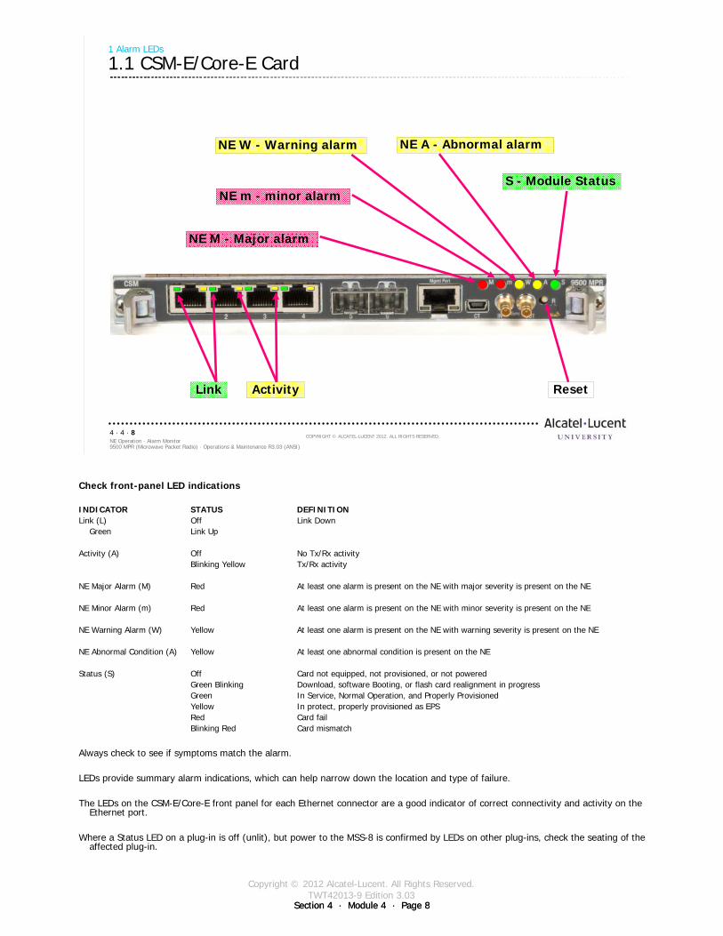
Section 4 · Module 4 · Page 8
Copyright © 2012 Alcatel-Lucent. All Rights Reserved.TWT42013-9 Edition 3.03
Section 4 · Module 4 · Page 8
9500 MPR (Microwave Packet Radio) · Operations & Maintenance R3.03 (ANSI)NE Operation · Alarm Monitor4 · 4 · 8
COPYRIGHT © ALCATEL-LUCENT 2012. ALL RIGHTS RESERVED.
1 Alarm LEDs
1.1 CSM-E/Core-E Card
S - Module StatusNE m - minor alarm
NE M - Major alarm
NE A - Abnormal alarmNE W - Warning alarm
ActivityLink Reset
Check front-panel LED indications
INDICATOR STATUS DEFINITIONLink (L) Off Link Down
Green Link Up
Activity (A) Off No Tx/Rx activityBlinking Yellow Tx/Rx activity
NE Major Alarm (M) Red At least one alarm is present on the NE with major severity is present on the NE
NE Minor Alarm (m) Red At least one alarm is present on the NE with minor severity is present on the NE
NE Warning Alarm (W) Yellow At least one alarm is present on the NE with warning severity is present on the NE
NE Abnormal Condition (A) Yellow At least one abnormal condition is present on the NE
Status (S) Off Card not equipped, not provisioned, or not poweredGreen Blinking Download, software Booting, or flash card realignment in progressGreen In Service, Normal Operation, and Properly ProvisionedYellow In protect, properly provisioned as EPSRed Card failBlinking Red Card mismatch
Always check to see if symptoms match the alarm.
LEDs provide summary alarm indications, which can help narrow down the location and type of failure.
The LEDs on the CSM-E/Core-E front panel for each Ethernet connector are a good indicator of correct connectivity and activity on the Ethernet port.
Where a Status LED on a plug-in is off (unlit), but power to the MSS-8 is confirmed by LEDs on other plug-ins, check the seating of the affected plug-in.
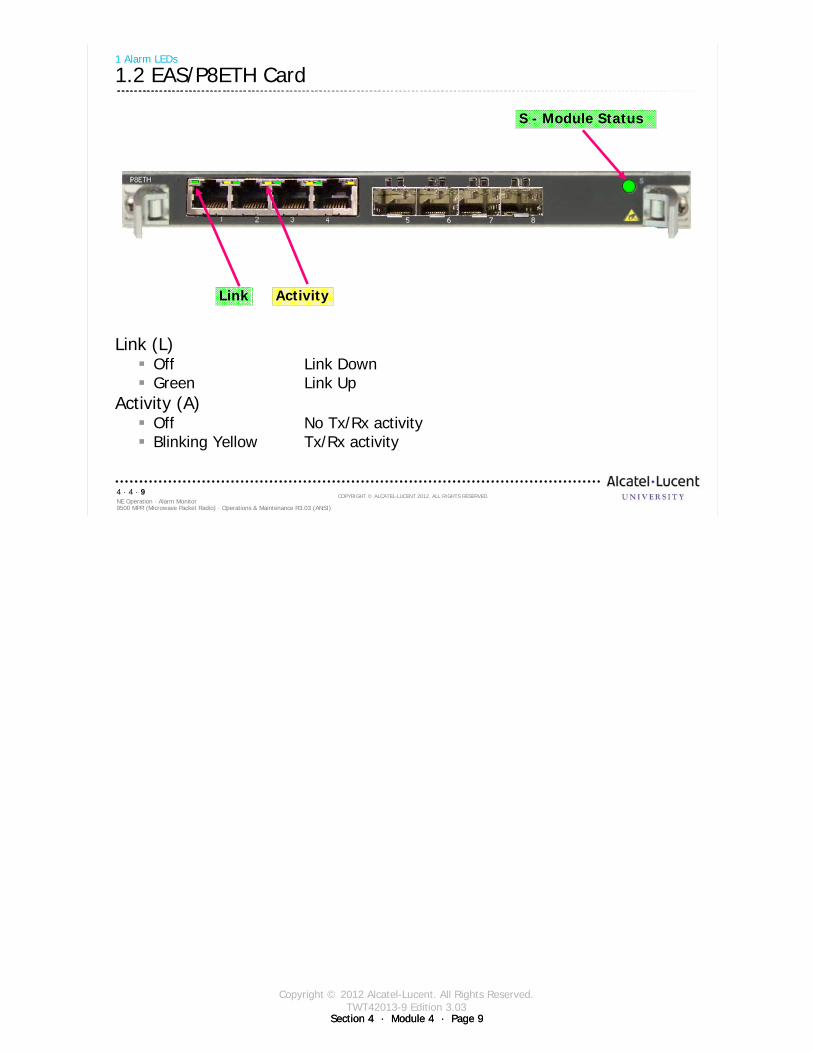
Section 4 · Module 4 · Page 9
Copyright © 2012 Alcatel-Lucent. All Rights Reserved.TWT42013-9 Edition 3.03
Section 4 · Module 4 · Page 9
9500 MPR (Microwave Packet Radio) · Operations & Maintenance R3.03 (ANSI)NE Operation · Alarm Monitor4 · 4 · 9
COPYRIGHT © ALCATEL-LUCENT 2012. ALL RIGHTS RESERVED.
1 Alarm LEDs
1.2 EAS/P8ETH Card
Link (L) Off Link DownGreen Link Up
Activity (A) Off No Tx/Rx activityBlinking Yellow Tx/Rx activity
S - Module Status
ActivityLink
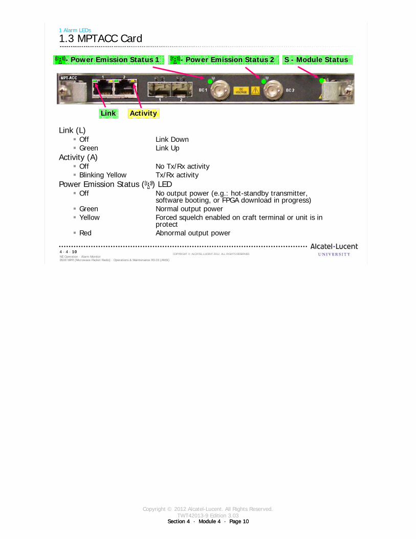
Section 4 · Module 4 · Page 10
Copyright © 2012 Alcatel-Lucent. All Rights Reserved.TWT42013-9 Edition 3.03
Section 4 · Module 4 · Page 10
9500 MPR (Microwave Packet Radio) · Operations & Maintenance R3.03 (ANSI)NE Operation · Alarm Monitor4 · 4 · 10
COPYRIGHT © ALCATEL-LUCENT 2012. ALL RIGHTS RESERVED.
1 Alarm LEDs
1.3 MPTACC Card
Link (L) Off Link DownGreen Link Up
Activity (A) Off No Tx/Rx activityBlinking Yellow Tx/Rx activity
Power Emission Status ( ) LEDOff No output power (e.g.: hot-standby transmitter,
software booting, or FPGA download in progress)Green Normal output powerYellow Forced squelch enabled on craft terminal or unit is in
protectRed Abnormal output power
M – Power Emission Status
S - Module Status
ActivityLink
- Power Emission Status 1 - Power Emission Status 2
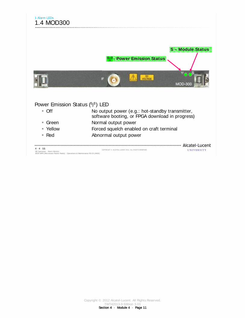
Section 4 · Module 4 · Page 11
Copyright © 2012 Alcatel-Lucent. All Rights Reserved.TWT42013-9 Edition 3.03
Section 4 · Module 4 · Page 11
9500 MPR (Microwave Packet Radio) · Operations & Maintenance R3.03 (ANSI)NE Operation · Alarm Monitor4 · 4 · 11
COPYRIGHT © ALCATEL-LUCENT 2012. ALL RIGHTS RESERVED.
- Power Emission Status
1 Alarm LEDs
1.4 MOD300
Power Emission Status ( ) LEDOff No output power (e.g.: hot-standby transmitter,
software booting, or FPGA download in progress)Green Normal output powerYellow Forced squelch enabled on craft terminalRed Abnormal output power
S – Module Status
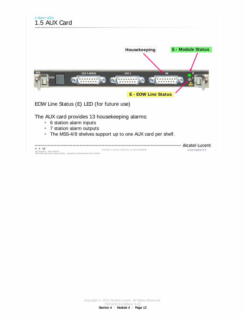
Section 4 · Module 4 · Page 12
Copyright © 2012 Alcatel-Lucent. All Rights Reserved.TWT42013-9 Edition 3.03
Section 4 · Module 4 · Page 12
9500 MPR (Microwave Packet Radio) · Operations & Maintenance R3.03 (ANSI)NE Operation · Alarm Monitor4 · 4 · 12
COPYRIGHT © ALCATEL-LUCENT 2012. ALL RIGHTS RESERVED.
1 Alarm LEDs
1.5 AUX Card
EOW Line Status (E) LED (for future use)
The AUX card provides 13 housekeeping alarms:6 station alarm inputs7 station alarm outputsThe MSS-4/8 shelves support up to one AUX card per shelf.
S - Module Status
E - EOW Line Status
Housekeeping
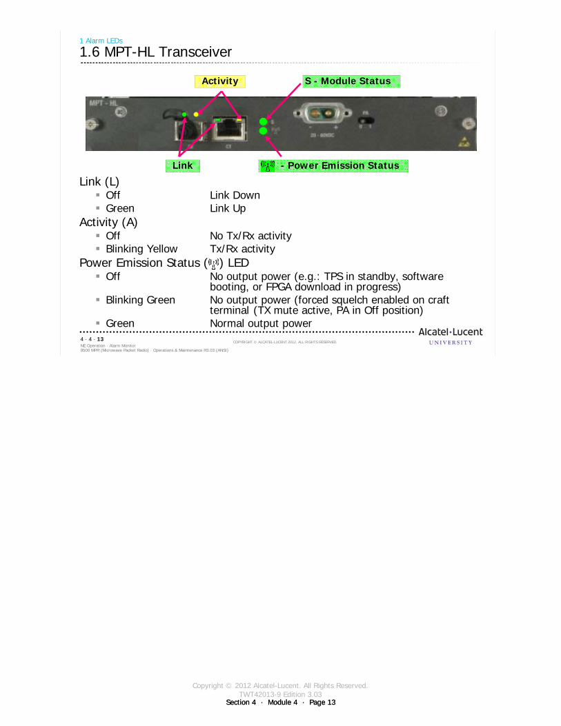
Section 4 · Module 4 · Page 13
Copyright © 2012 Alcatel-Lucent. All Rights Reserved.TWT42013-9 Edition 3.03
Section 4 · Module 4 · Page 13
9500 MPR (Microwave Packet Radio) · Operations & Maintenance R3.03 (ANSI)NE Operation · Alarm Monitor4 · 4 · 13
COPYRIGHT © ALCATEL-LUCENT 2012. ALL RIGHTS RESERVED.
1 Alarm LEDs
1.6 MPT-HL Transceiver
Link (L) Off Link DownGreen Link Up
Activity (A) Off No Tx/Rx activityBlinking Yellow Tx/Rx activity
Power Emission Status ( ) LEDOff No output power (e.g.: TPS in standby, software
booting, or FPGA download in progress)Blinking Green No output power (forced squelch enabled on craft
terminal (TX mute active, PA in Off position)Green Normal output power
Activity
Link
S - Module Status
- Power Emission Status
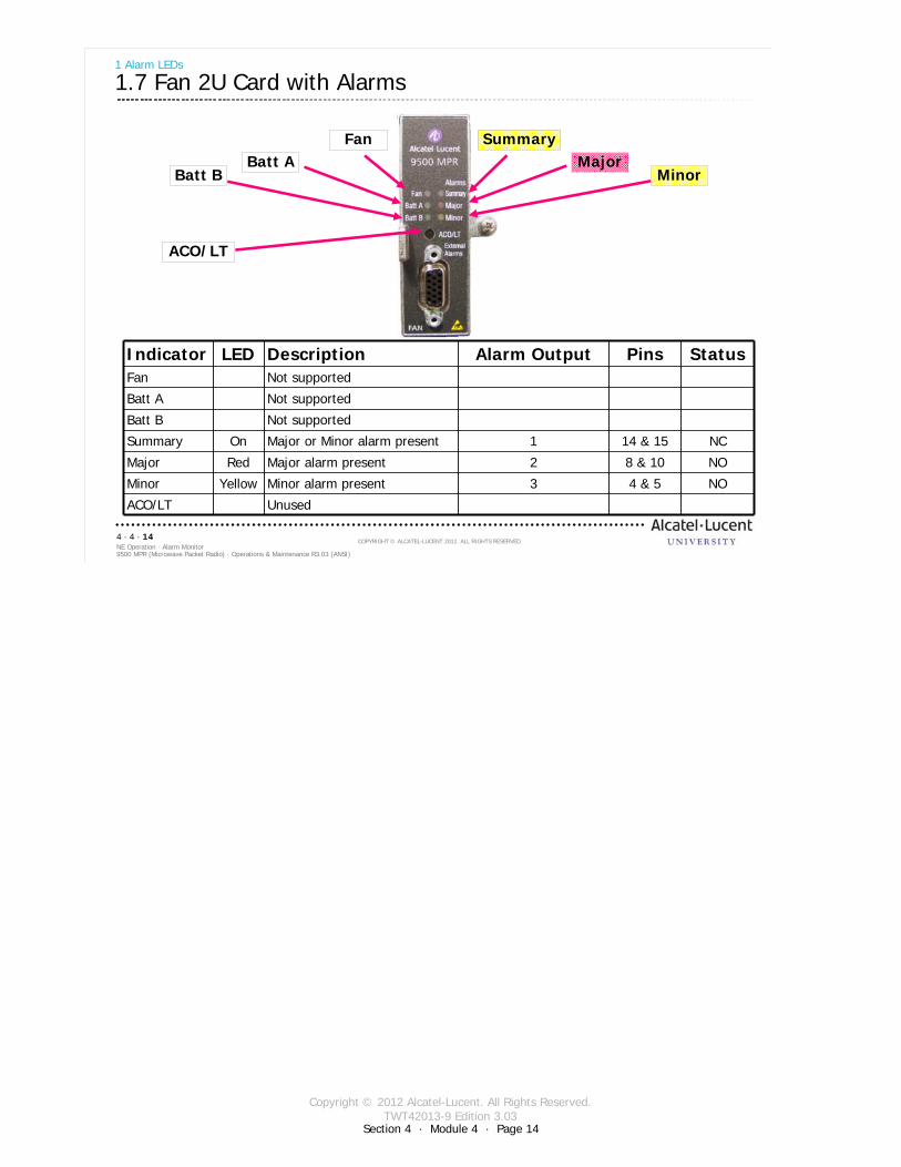
Section 4 · Module 4 · Page 14
Copyright © 2012 Alcatel-Lucent. All Rights Reserved.TWT42013-9 Edition 3.03
9500 MPR (Microwave Packet Radio) · Operations & Maintenance R3.03 (ANSI)NE Operation · Alarm Monitor4 · 4 · 14
COPYRIGHT © ALCATEL-LUCENT 2012. ALL RIGHTS RESERVED.
1 Alarm LEDs
1.7 Fan 2U Card with Alarms
SummaryMajor
Minor
FanBatt A
Batt B
ACO/LT
Indicator LED Description Alarm Output Pins StatusFan Not supported
Batt A Not supported
Batt B Not supported
Summary On Major or Minor alarm present 1 14 & 15 NC
Major Red Major alarm present 2 8 & 10 NO
Minor Yellow Minor alarm present 3 4 & 5 NO
ACO/LT Unused

Section 4 · Module 4 · Page 15
Copyright © 2012 Alcatel-Lucent. All Rights Reserved.TWT42013-9 Edition 3.03
Section 4 · Module 4 · Page 15
9500 MPR (Microwave Packet Radio) · Operations & Maintenance R3.03 (ANSI)NE Operation · Alarm Monitor4 · 4 · 15
COPYRIGHT © ALCATEL-LUCENT 2012. ALL RIGHTS RESERVED.
1 Alarm LEDs
1.8 MSS-1c
NE m - minor alarm
NE M - Major alarm
NE A - Abnormal alarm
NE W - Warning alarm
ActivityLink
MPT 1 - Status
Check front-panel LED indications
INDICATOR STATUS DEFINITIONLink (L) Off Link Down
Green Link Up
Activity (A) Off No Tx/Rx activityBlinking Yellow Tx/Rx activity
Major Alarm (M) Red At least one alarm is present on the NE with major severity
Minor Alarm (m) Red At least one alarm is present on the NE with minor severity (not supported)
Warning Alarm (W) Yellow At least one alarm is present on the NE with warning severity (not supported)
Abnormal Condition (A) Yellow At least one abnormal condition is present on the NE
- Tx Power muted by operator- ACM frozen by operator- MPT loopback active
MPT1 Off MPT is not emitting power according with the known configurationGreen MPT is emitting power as expected according the known configurationYellow MPT is not emitting power due to a forced Squelch conditionRed MPT is ABNORMALLY emitting power
MPT2 (not supported)
At start-up the MSS-1c:lights on all the alarm LEDs (Major, Minor, Warning and Abnormal)lights on the MPT LED as yellow, then this LED will be green, red, or yellow, as explained above.

Section 4 · Module 4 · Page 16
Copyright © 2012 Alcatel-Lucent. All Rights Reserved.TWT42013-9 Edition 3.03
Section 4 · Module 4 · Page 16
9500 MPR (Microwave Packet Radio) · Operations & Maintenance R3.03 (ANSI)NE Operation · Alarm Monitor4 · 4 · 16
COPYRIGHT © ALCATEL-LUCENT 2012. ALL RIGHTS RESERVED.
Blank page
Switch to notes view!
This page intentionally left blank

Section 4 · Module 4 · Page 17
Copyright © 2012 Alcatel-Lucent. All Rights Reserved.TWT42013-9 Edition 3.03
9500 MPR (Microwave Packet Radio) · Operations & Maintenance R3.03 (ANSI)NE Operation · Alarm Monitor4 · 4 · 17
COPYRIGHT © ALCATEL-LUCENT 2012. ALL RIGHTS RESERVED.
2 Alarms in Network Overview

Section 4 · Module 4 · Page 18
Copyright © 2012 Alcatel-Lucent. All Rights Reserved.TWT42013-9 Edition 3.03
Section 4 · Module 4 · Page 18
9500 MPR (Microwave Packet Radio) · Operations & Maintenance R3.03 (ANSI)NE Operation · Alarm Monitor4 · 4 · 18
COPYRIGHT © ALCATEL-LUCENT 2012. ALL RIGHTS RESERVED.
2 Alarms in Network Overview
2.1 Alarm Synthesis
1
When you are connected to an NE, you get an Alarm overview.
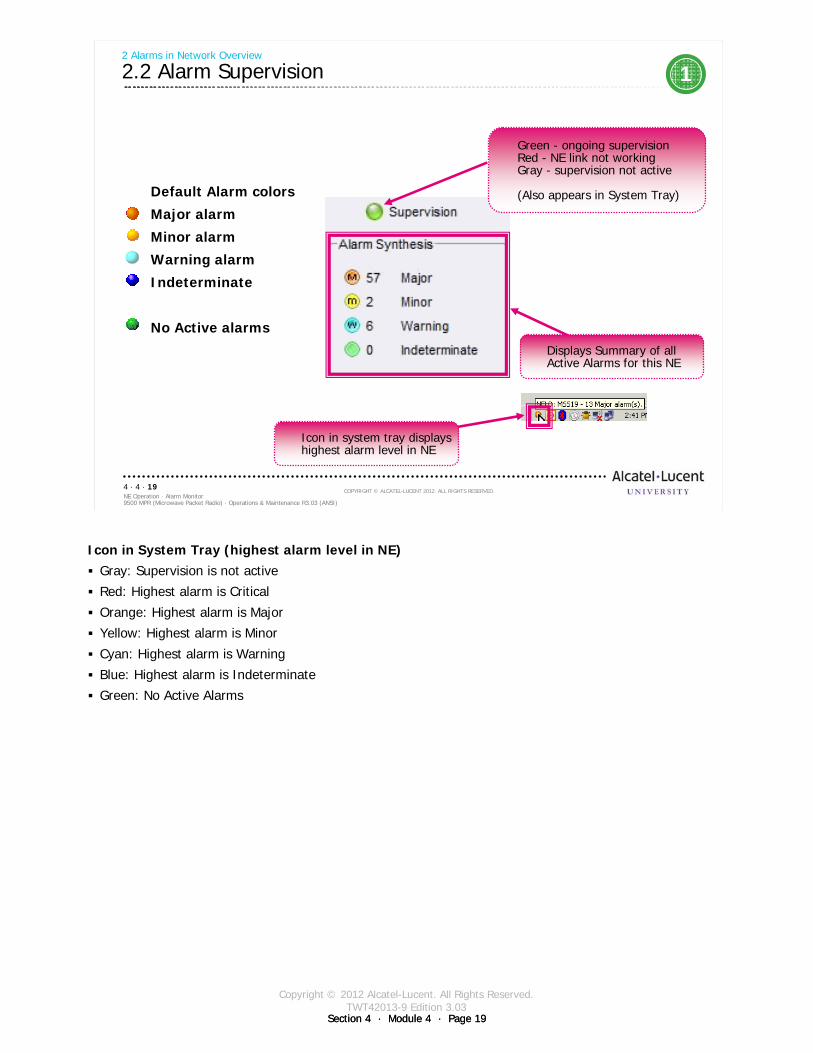
Section 4 · Module 4 · Page 19
Copyright © 2012 Alcatel-Lucent. All Rights Reserved.TWT42013-9 Edition 3.03
Section 4 · Module 4 · Page 19
9500 MPR (Microwave Packet Radio) · Operations & Maintenance R3.03 (ANSI)NE Operation · Alarm Monitor4 · 4 · 19
COPYRIGHT © ALCATEL-LUCENT 2012. ALL RIGHTS RESERVED.
2 Alarms in Network Overview
2.2 Alarm Supervision 1
Default Alarm colors
Major alarm
Minor alarm
Warning alarm
Indeterminate
No Active alarms
Green - ongoing supervisionRed - NE link not workingGray - supervision not active
(Also appears in System Tray)
Displays Summary of all Active Alarms for this NE
Icon in system tray displays highest alarm level in NE
Icon in System Tray (highest alarm level in NE)Gray: Supervision is not active
Red: Highest alarm is Critical
Orange: Highest alarm is Major
Yellow: Highest alarm is Minor
Cyan: Highest alarm is Warning
Blue: Highest alarm is Indeterminate
Green: No Active Alarms

Section 4 · Module 4 · Page 20
Copyright © 2012 Alcatel-Lucent. All Rights Reserved.TWT42013-9 Edition 3.03
Section 4 · Module 4 · Page 20
9500 MPR (Microwave Packet Radio) · Operations & Maintenance R3.03 (ANSI)NE Operation · Alarm Monitor4 · 4 · 20
COPYRIGHT © ALCATEL-LUCENT 2012. ALL RIGHTS RESERVED.
Blank page
Switch to notes view!
This page intentionally left blank

Section 4 · Module 4 · Page 21
Copyright © 2012 Alcatel-Lucent. All Rights Reserved.TWT42013-9 Edition 3.03
9500 MPR (Microwave Packet Radio) · Operations & Maintenance R3.03 (ANSI)NE Operation · Alarm Monitor4 · 4 · 21
COPYRIGHT © ALCATEL-LUCENT 2012. ALL RIGHTS RESERVED.
3 Alarm in Main Views
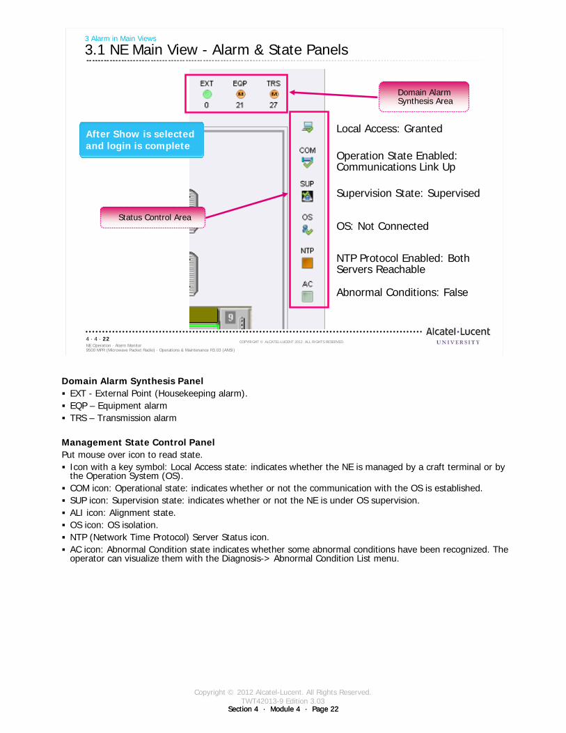
Section 4 · Module 4 · Page 22
Copyright © 2012 Alcatel-Lucent. All Rights Reserved.TWT42013-9 Edition 3.03
Section 4 · Module 4 · Page 22
9500 MPR (Microwave Packet Radio) · Operations & Maintenance R3.03 (ANSI)NE Operation · Alarm Monitor4 · 4 · 22
COPYRIGHT © ALCATEL-LUCENT 2012. ALL RIGHTS RESERVED.
3 Alarm in Main Views
3.1 NE Main View - Alarm & State Panels
Local Access: Granted
Operation State Enabled: Communications Link Up
Supervision State: Supervised
OS: Not Connected
NTP Protocol Enabled: Both Servers Reachable
Abnormal Conditions: False
Domain Alarm Synthesis Area
Status Control Area
After Show is selected and login is complete
Domain Alarm Synthesis PanelEXT - External Point (Housekeeping alarm). EQP – Equipment alarm TRS – Transmission alarm
Management State Control PanelPut mouse over icon to read state.
Icon with a key symbol: Local Access state: indicates whether the NE is managed by a craft terminal or by the Operation System (OS).COM icon: Operational state: indicates whether or not the communication with the OS is established. SUP icon: Supervision state: indicates whether or not the NE is under OS supervision. ALI icon: Alignment state.OS icon: OS isolation.NTP (Network Time Protocol) Server Status icon.AC icon: Abnormal Condition state indicates whether some abnormal conditions have been recognized. The operator can visualize them with the Diagnosis-> Abnormal Condition List menu.
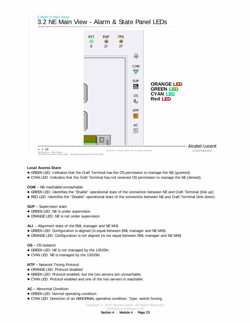
Section 4 · Module 4 · Page 23
Copyright © 2012 Alcatel-Lucent. All Rights Reserved.TWT42013-9 Edition 3.03
Section 4 · Module 4 · Page 23
9500 MPR (Microwave Packet Radio) · Operations & Maintenance R3.03 (ANSI)NE Operation · Alarm Monitor4 · 4 · 23
COPYRIGHT © ALCATEL-LUCENT 2012. ALL RIGHTS RESERVED.
3 Alarm in Main Views
3.2 NE Main View - Alarm & State Panel LEDs
ORANGE LEDLEDGREEN LEDLEDCYAN LEDLEDRed LEDLED
Local Access StateGREEN LED: Indicates that the Craft Terminal has the OS permission to manage the NE (granted).CYAN LED: Indicates that the Craft Terminal has not received OS permission to manage the NE (denied).
COM – NE reachable/unreachableGREEN LED: Identifies the “Enable” operational state of the connection between NE and Craft Terminal (link up).RED LED: Identifies the “Disable” operational state of the connection between NE and Craft Terminal (link down).
SUP – Supervision stateGREEN LED: NE is under supervision ORANGE LED: NE is not under supervision
ALI – Alignment state of the EML manager and NE MIB.GREEN LED: Configuration is aligned (is equal between EML manager and NE MIB).ORANGE LED: Configuration is not aligned (is not equal between EML manager and NE MIB).
OS – OS isolationGREEN LED: NE is not managed by the 1353SH.CYAN LED: NE is managed by the 1353SH.
NTP – Network Timing ProtocolORANGE LED: Protocol disabledGREEN LED: Protocol enabled, but the two servers are unreachable.CYAN LED: Protocol enabled and one of the two servers is reachable.
AC – Abnormal ConditionGREEN LED: Normal operating condition.CYAN LED: Detection of an ABNORMAL operative condition. Type: switch forcing.
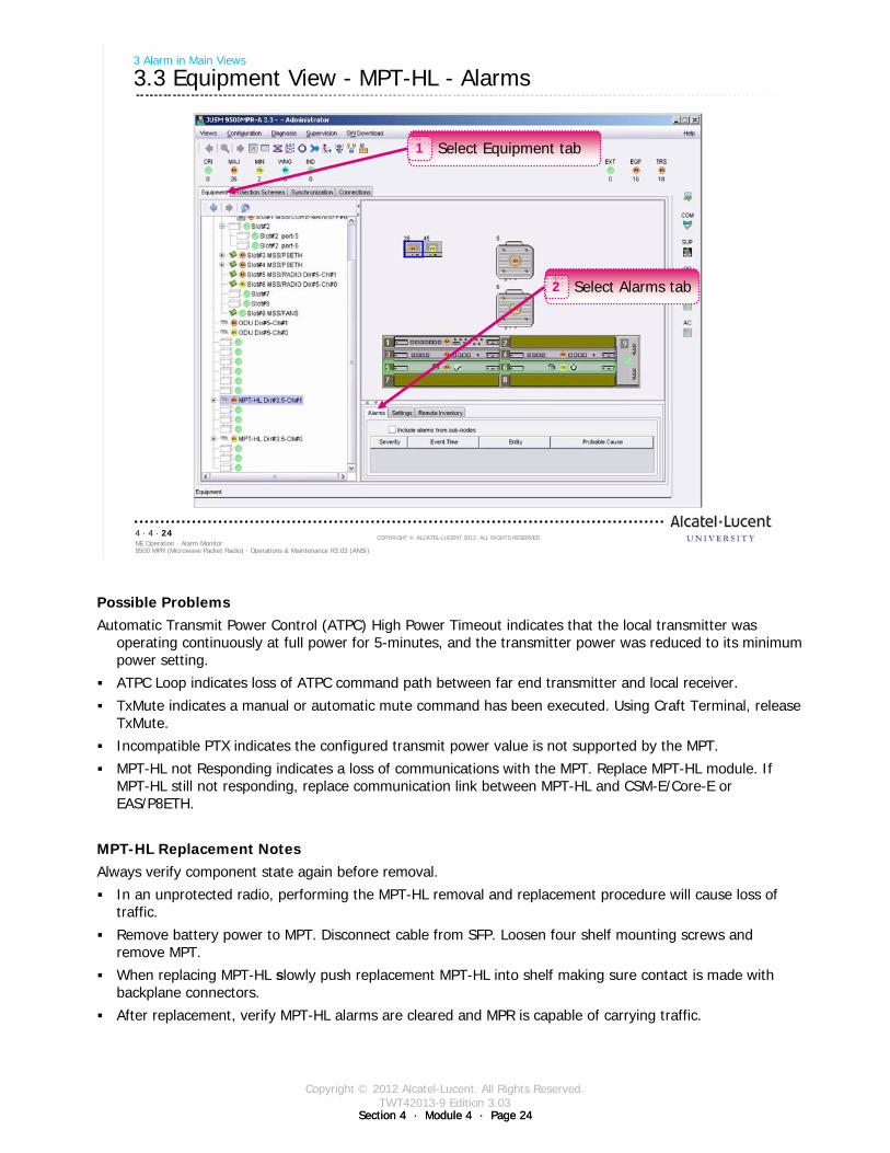
Section 4 · Module 4 · Page 24
Copyright © 2012 Alcatel-Lucent. All Rights Reserved.TWT42013-9 Edition 3.03
Section 4 · Module 4 · Page 24
9500 MPR (Microwave Packet Radio) · Operations & Maintenance R3.03 (ANSI)NE Operation · Alarm Monitor4 · 4 · 24
COPYRIGHT © ALCATEL-LUCENT 2012. ALL RIGHTS RESERVED.
3 Alarm in Main Views
3.3 Equipment View - MPT-HL - Alarms
Select Equipment tab1
Select Alarms tab2
Possible ProblemsAutomatic Transmit Power Control (ATPC) High Power Timeout indicates that the local transmitter was
operating continuously at full power for 5-minutes, and the transmitter power was reduced to its minimum power setting.
ATPC Loop indicates loss of ATPC command path between far end transmitter and local receiver.
TxMute indicates a manual or automatic mute command has been executed. Using Craft Terminal, release TxMute.
Incompatible PTX indicates the configured transmit power value is not supported by the MPT.
MPT-HL not Responding indicates a loss of communications with the MPT. Replace MPT-HL module. If MPT-HL still not responding, replace communication link between MPT-HL and CSM-E/Core-E or EAS/P8ETH.
MPT-HL Replacement NotesAlways verify component state again before removal.
In an unprotected radio, performing the MPT-HL removal and replacement procedure will cause loss of traffic.
Remove battery power to MPT. Disconnect cable from SFP. Loosen four shelf mounting screws and remove MPT.
When replacing MPT-HL slowly push replacement MPT-HL into shelf making sure contact is made with backplane connectors.
After replacement, verify MPT-HL alarms are cleared and MPR is capable of carrying traffic.

Section 4 · Module 4 · Page 25
Copyright © 2012 Alcatel-Lucent. All Rights Reserved.TWT42013-9 Edition 3.03
9500 MPR (Microwave Packet Radio) · Operations & Maintenance R3.03 (ANSI)NE Operation · Alarm Monitor4 · 4 · 25
COPYRIGHT © ALCATEL-LUCENT 2012. ALL RIGHTS RESERVED.
4 Alarm Monitor
Refer to 9500 MPR Operation and Administration, 3EM23954AHAA, DLP-113 for more details
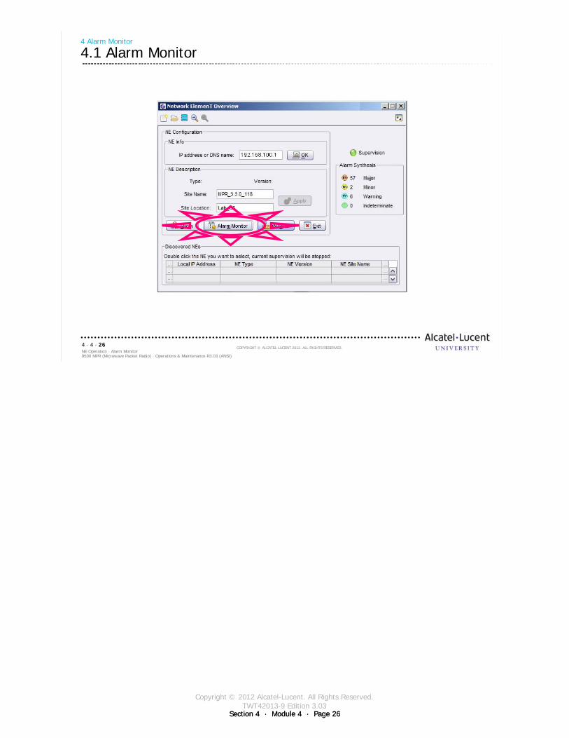
Section 4 · Module 4 · Page 26
Copyright © 2012 Alcatel-Lucent. All Rights Reserved.TWT42013-9 Edition 3.03
Section 4 · Module 4 · Page 26
9500 MPR (Microwave Packet Radio) · Operations & Maintenance R3.03 (ANSI)NE Operation · Alarm Monitor4 · 4 · 26
COPYRIGHT © ALCATEL-LUCENT 2012. ALL RIGHTS RESERVED.
4 Alarm Monitor
4.1 Alarm Monitor
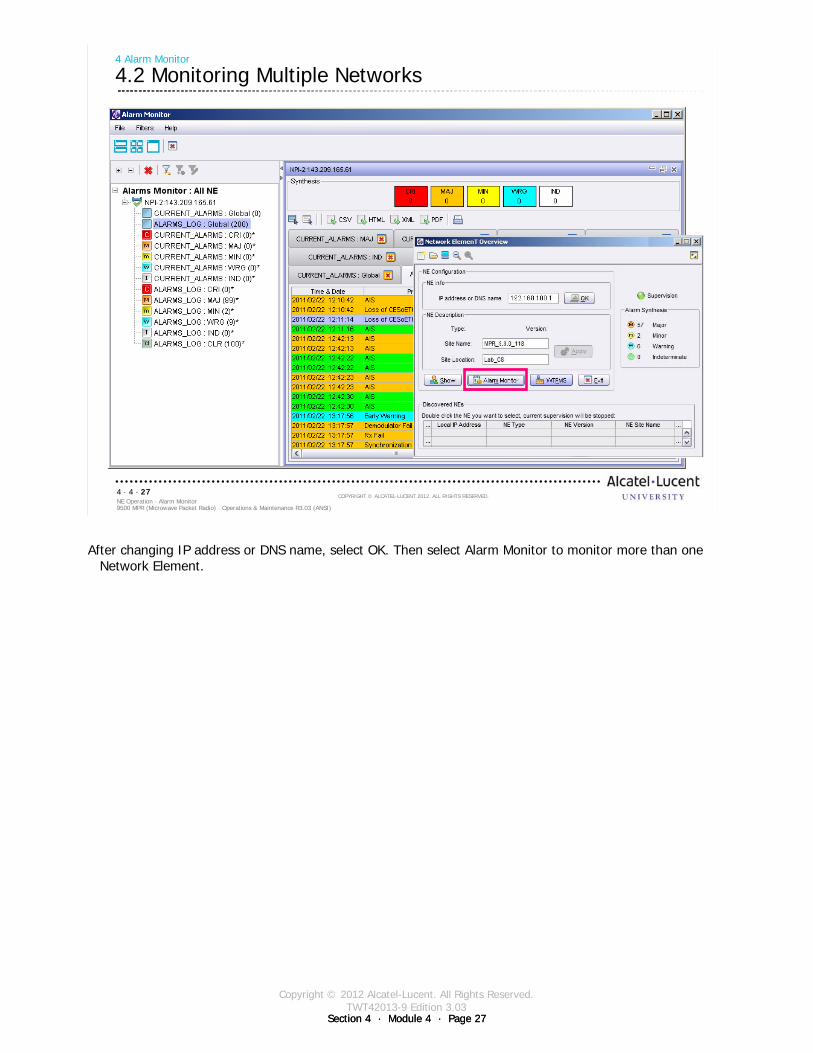
Section 4 · Module 4 · Page 27
Copyright © 2012 Alcatel-Lucent. All Rights Reserved.TWT42013-9 Edition 3.03
Section 4 · Module 4 · Page 27
9500 MPR (Microwave Packet Radio) · Operations & Maintenance R3.03 (ANSI)NE Operation · Alarm Monitor4 · 4 · 27
COPYRIGHT © ALCATEL-LUCENT 2012. ALL RIGHTS RESERVED.
4 Alarm Monitor
4.2 Monitoring Multiple Networks
After changing IP address or DNS name, select OK. Then select Alarm Monitor to monitor more than one Network Element.
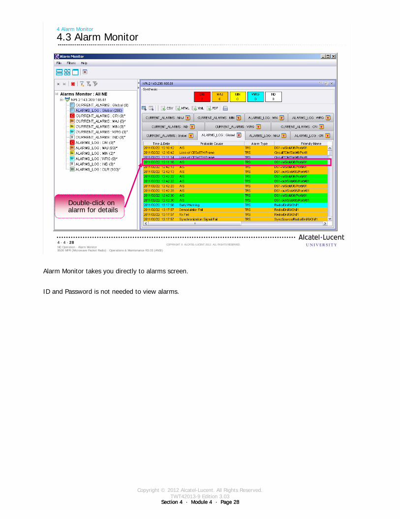
Section 4 · Module 4 · Page 28
Copyright © 2012 Alcatel-Lucent. All Rights Reserved.TWT42013-9 Edition 3.03
Section 4 · Module 4 · Page 28
9500 MPR (Microwave Packet Radio) · Operations & Maintenance R3.03 (ANSI)NE Operation · Alarm Monitor4 · 4 · 28
COPYRIGHT © ALCATEL-LUCENT 2012. ALL RIGHTS RESERVED.
4 Alarm Monitor
4.3 Alarm Monitor
Double-click on alarm for details
Alarm Monitor takes you directly to alarms screen.
ID and Password is not needed to view alarms.
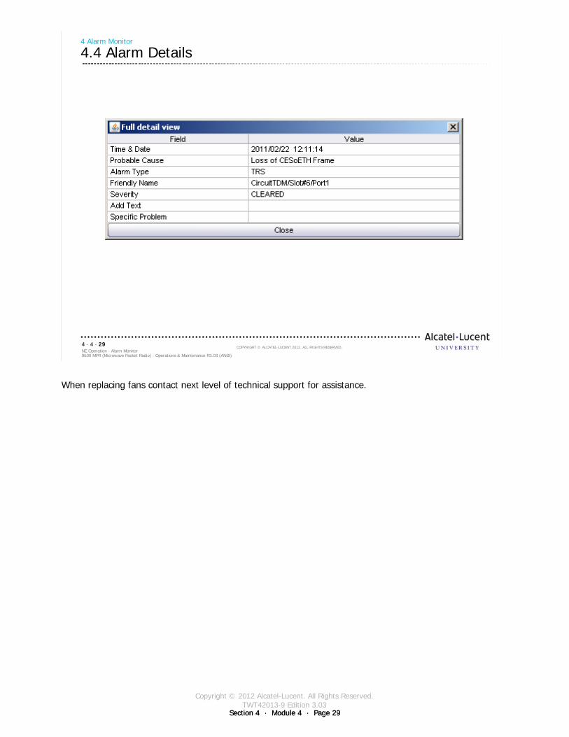
Section 4 · Module 4 · Page 29
Copyright © 2012 Alcatel-Lucent. All Rights Reserved.TWT42013-9 Edition 3.03
Section 4 · Module 4 · Page 29
9500 MPR (Microwave Packet Radio) · Operations & Maintenance R3.03 (ANSI)NE Operation · Alarm Monitor4 · 4 · 29
COPYRIGHT © ALCATEL-LUCENT 2012. ALL RIGHTS RESERVED.
4 Alarm Monitor
4.4 Alarm Details
When replacing fans contact next level of technical support for assistance.

Section 4 · Module 4 · Page 30
Copyright © 2012 Alcatel-Lucent. All Rights Reserved.TWT42013-9 Edition 3.03
Section 4 · Module 4 · Page 30
9500 MPR (Microwave Packet Radio) · Operations & Maintenance R3.03 (ANSI)NE Operation · Alarm Monitor4 · 4 · 30
COPYRIGHT © ALCATEL-LUCENT 2012. ALL RIGHTS RESERVED.
Blank page
Switch to notes view!
This page intentionally left blank
Section 4 · Module 4 · Page 31
Copyright © 2012 Alcatel-Lucent. All Rights Reserved.TWT42013-9 Edition 3.03
9500 MPR (Microwave Packet Radio) · Operations & Maintenance R3.03 (ANSI)NE Operation · Alarm Monitor4 · 4 · 31
COPYRIGHT © ALCATEL-LUCENT 2012. ALL RIGHTS RESERVED.
Exercise
Time allowed:
Lab Exercise 12Alarm Monitor

Section 4 · Module 4 · Page 32
Copyright © 2012 Alcatel-Lucent. All Rights Reserved.TWT42013-9 Edition 3.03
Section 4 · Module 4 · Page 32
9500 MPR (Microwave Packet Radio) · Operations & Maintenance R3.03 (ANSI)NE Operation · Alarm Monitor4 · 4 · 32
COPYRIGHT © ALCATEL-LUCENT 2012. ALL RIGHTS RESERVED.
Blank page
Switch to notes view!
This page intentionally left blank

Section 4 · Module 4 · Page 33
Copyright © 2012 Alcatel-Lucent. All Rights Reserved.TWT42013-9 Edition 3.03
9500 MPR (Microwave Packet Radio) · Operations & Maintenance R3.03 (ANSI)NE Operation · Alarm Monitor4 · 4 · 33
COPYRIGHT © ALCATEL-LUCENT 2012. ALL RIGHTS RESERVED.
5 MPT-HL RSL History
Refer to 9500 MPR Operation and Administration, 3EM23954AHAA, DLP-122 for more details
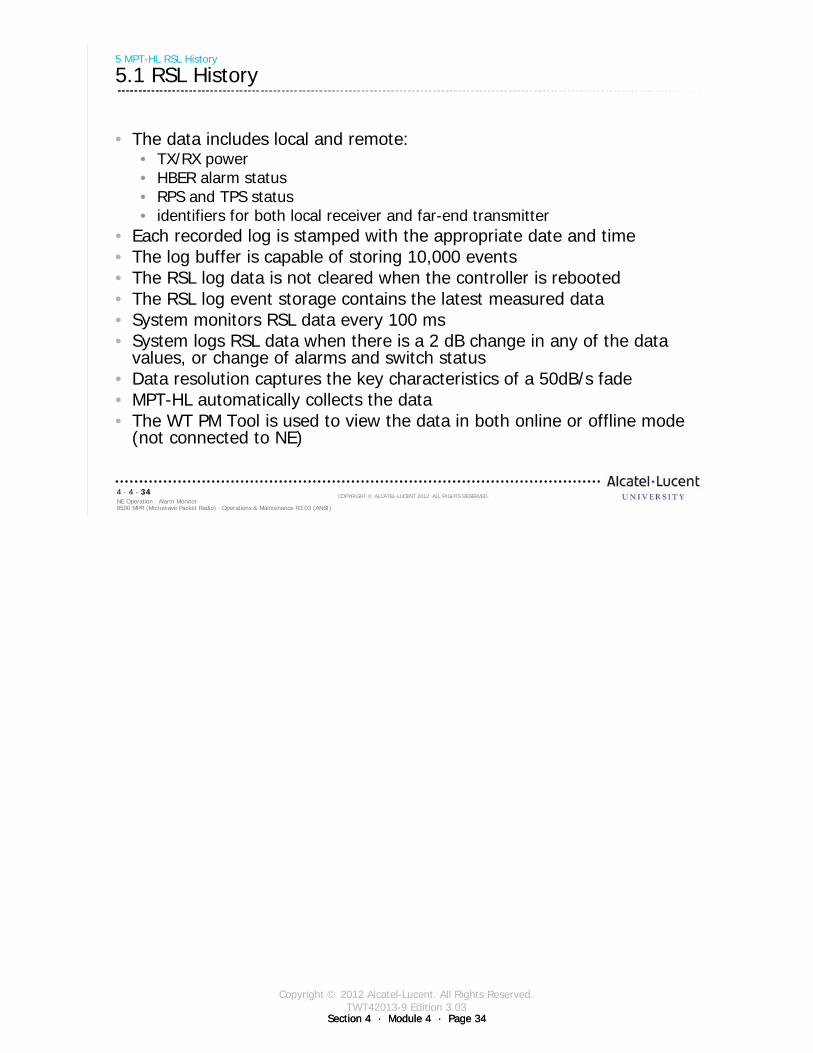
Section 4 · Module 4 · Page 34
Copyright © 2012 Alcatel-Lucent. All Rights Reserved.TWT42013-9 Edition 3.03
Section 4 · Module 4 · Page 34
9500 MPR (Microwave Packet Radio) · Operations & Maintenance R3.03 (ANSI)NE Operation · Alarm Monitor4 · 4 · 34
COPYRIGHT © ALCATEL-LUCENT 2012. ALL RIGHTS RESERVED.
5 MPT-HL RSL History
5.1 RSL History
• The data includes local and remote:• TX/RX power• HBER alarm status• RPS and TPS status• identifiers for both local receiver and far-end transmitter
• Each recorded log is stamped with the appropriate date and time• The log buffer is capable of storing 10,000 events• The RSL log data is not cleared when the controller is rebooted • The RSL log event storage contains the latest measured data • System monitors RSL data every 100 ms• System logs RSL data when there is a 2 dB change in any of the data
values, or change of alarms and switch status• Data resolution captures the key characteristics of a 50dB/s fade• MPT-HL automatically collects the data• The WT PM Tool is used to view the data in both online or offline mode
(not connected to NE)
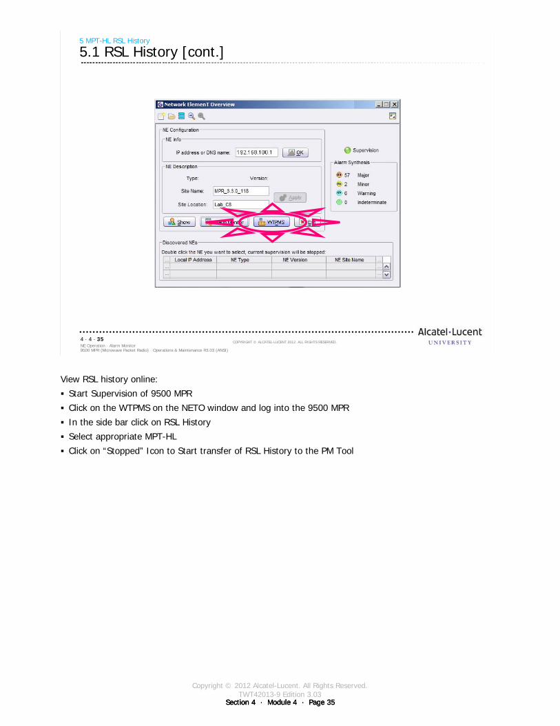
Section 4 · Module 4 · Page 35
Copyright © 2012 Alcatel-Lucent. All Rights Reserved.TWT42013-9 Edition 3.03
Section 4 · Module 4 · Page 35Section 4 · Module 4 · Page 35
9500 MPR (Microwave Packet Radio) · Operations & Maintenance R3.03 (ANSI)NE Operation · Alarm Monitor4 · 4 · 35
COPYRIGHT © ALCATEL-LUCENT 2012. ALL RIGHTS RESERVED.
5 MPT-HL RSL History
5.1 RSL History [cont.]
View RSL history online:
Start Supervision of 9500 MPR
Click on the WTPMS on the NETO window and log into the 9500 MPR
In the side bar click on RSL History
Select appropriate MPT-HL
Click on “Stopped” Icon to Start transfer of RSL History to the PM Tool

Section 4 · Module 4 · Page 36
Copyright © 2012 Alcatel-Lucent. All Rights Reserved.TWT42013-9 Edition 3.03
Section 4 · Module 4 · Page 36
9500 MPR (Microwave Packet Radio) · Operations & Maintenance R3.03 (ANSI)NE Operation · Alarm Monitor4 · 4 · 36
COPYRIGHT © ALCATEL-LUCENT 2012. ALL RIGHTS RESERVED.
5 MPT-HL RSL History
5.2 View RSL History - Online
Select RSL History1
Select MPT-HL2
Click Stopped to start data download3
Indicates download in progress
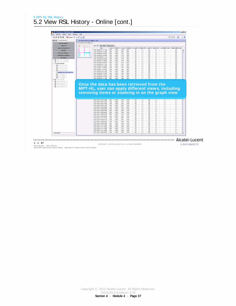
Section 4 · Module 4 · Page 37
Copyright © 2012 Alcatel-Lucent. All Rights Reserved.TWT42013-9 Edition 3.03
Section 4 · Module 4 · Page 37
9500 MPR (Microwave Packet Radio) · Operations & Maintenance R3.03 (ANSI)NE Operation · Alarm Monitor4 · 4 · 37
COPYRIGHT © ALCATEL-LUCENT 2012. ALL RIGHTS RESERVED.
5 MPT-HL RSL History
5.2 View RSL History - Online [cont.]
Once the data has been retrieved from the MPT-HL, user can apply different views, including removing items or zooming in on the graph view

Section 4 · Module 4 · Page 38
Copyright © 2012 Alcatel-Lucent. All Rights Reserved.TWT42013-9 Edition 3.03
Section 4 · Module 4 · Page 38
9500 MPR (Microwave Packet Radio) · Operations & Maintenance R3.03 (ANSI)NE Operation · Alarm Monitor4 · 4 · 38
COPYRIGHT © ALCATEL-LUCENT 2012. ALL RIGHTS RESERVED.
Ability to split Working and Protect RSL
5 MPT-HL RSL History
5.2 View RSL History - Online [cont.]
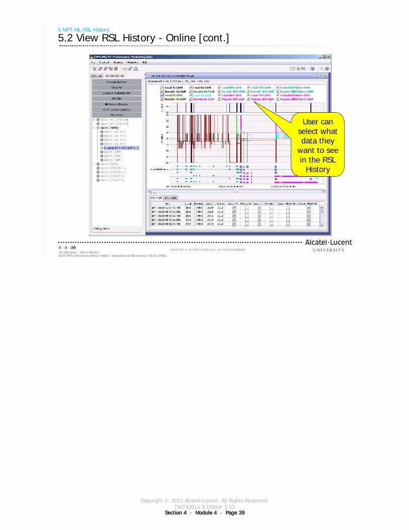
Section 4 · Module 4 · Page 39
Copyright © 2012 Alcatel-Lucent. All Rights Reserved.TWT42013-9 Edition 3.03
Section 4 · Module 4 · Page 39
9500 MPR (Microwave Packet Radio) · Operations & Maintenance R3.03 (ANSI)NE Operation · Alarm Monitor4 · 4 · 39
COPYRIGHT © ALCATEL-LUCENT 2012. ALL RIGHTS RESERVED.
User can select what data they
want to see in the RSL
History
5 MPT-HL RSL History
5.2 View RSL History - Online [cont.]
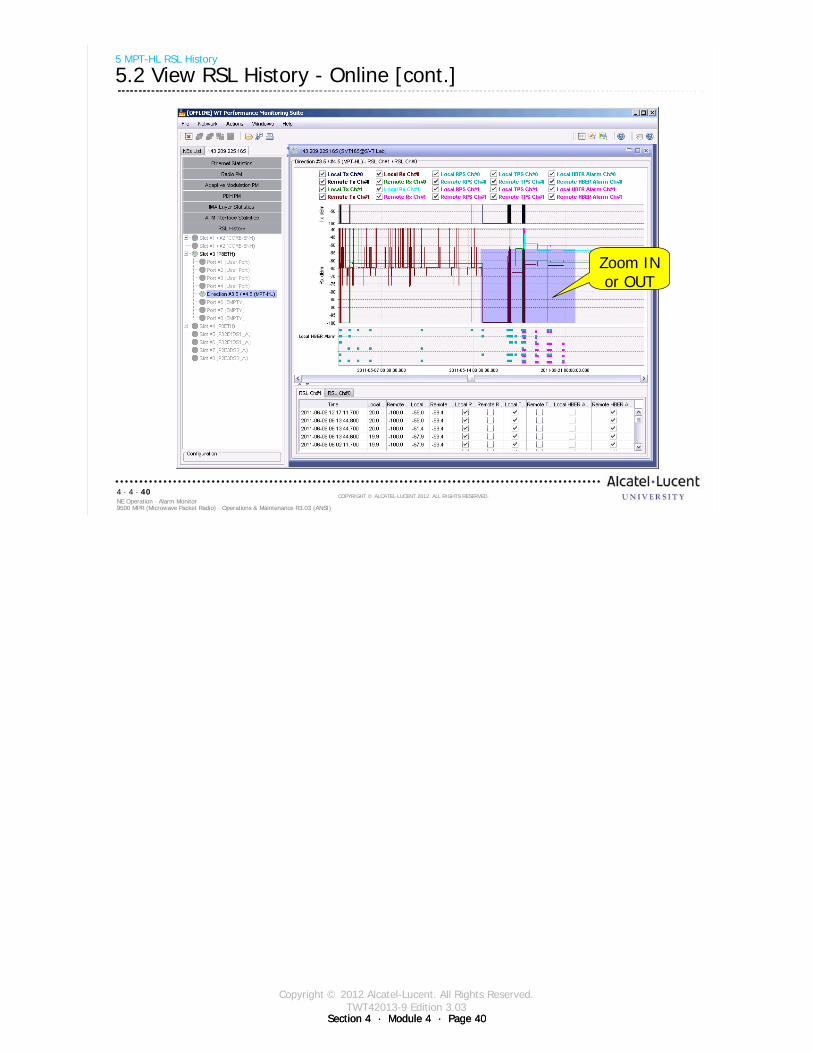
Section 4 · Module 4 · Page 40
Copyright © 2012 Alcatel-Lucent. All Rights Reserved.TWT42013-9 Edition 3.03
Section 4 · Module 4 · Page 40
9500 MPR (Microwave Packet Radio) · Operations & Maintenance R3.03 (ANSI)NE Operation · Alarm Monitor4 · 4 · 40
COPYRIGHT © ALCATEL-LUCENT 2012. ALL RIGHTS RESERVED.
Zoom IN or OUT
5 MPT-HL RSL History
5.2 View RSL History - Online [cont.]

Section 4 · Module 4 · Page 41
Copyright © 2012 Alcatel-Lucent. All Rights Reserved.TWT42013-9 Edition 3.03
Section 4 · Module 4 · Page 41
9500 MPR (Microwave Packet Radio) · Operations & Maintenance R3.03 (ANSI)NE Operation · Alarm Monitor4 · 4 · 41
COPYRIGHT © ALCATEL-LUCENT 2012. ALL RIGHTS RESERVED.
5 MPT-HL RSL History
5.2 View RSL History - Online [cont.]
To save the file to view in Off-line mode:Click on the Floppy Disk IconUser will be prompted to provide a file name /description
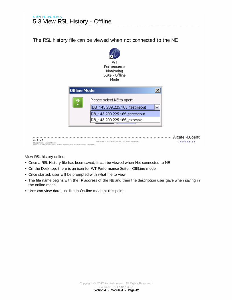
Section 4 · Module 4 · Page 42
Copyright © 2012 Alcatel-Lucent. All Rights Reserved.TWT42013-9 Edition 3.03
Section 4 · Module 4 · Page 42
9500 MPR (Microwave Packet Radio) · Operations & Maintenance R3.03 (ANSI)NE Operation · Alarm Monitor4 · 4 · 42
COPYRIGHT © ALCATEL-LUCENT 2012. ALL RIGHTS RESERVED.
5 MPT-HL RSL History
5.3 View RSL History - Offline
The RSL history file can be viewed when not connected to the NE
View RSL history online:
Once a RSL History file has been saved, it can be viewed when Not connected to NE
On the Desk top, there is an icon for WT Performance Suite - OfflLine mode
Once started, user will be prompted with what file to view
The file name begins with the IP address of the NE and then the description user gave when saving in the online mode
User can view data just like in On-line mode at this point
Section 4 · Module 4 · Page 43
Copyright © 2012 Alcatel-Lucent. All Rights Reserved.TWT42013-9 Edition 3.03
Section 4 · Module 4 · Page 43
9500 MPR (Microwave Packet Radio) · Operations & Maintenance R3.03 (ANSI)NE Operation · Alarm Monitor4 · 4 · 43
COPYRIGHT © ALCATEL-LUCENT 2012. ALL RIGHTS RESERVED.
Module summary
Recognize the meaning of Status and Alarm LEDsFind MPT-HL alarm display using Equipment MenuFind alarm display using Diagnosis MenuFind alarm display using Alarm MonitorList some causes of MPT-HL alarmsList details of an alarmMPT-HL RSL history

Section 4 · Module 4 · Page 44
Copyright © 2012 Alcatel-Lucent. All Rights Reserved.TWT42013-9 Edition 3.03
Section 4 · Module 4 · Page 44
9500 MPR (Microwave Packet Radio) · Operations & Maintenance R3.03 (ANSI)NE Operation · Alarm Monitor4 · 4 · 44
COPYRIGHT © ALCATEL-LUCENT 2012. ALL RIGHTS RESERVED.
End of moduleAlarm Monitor

Copyright © 2012 Alcatel-Lucent. All Rights Reserved.TWT42013-10 Edition 3.03
Section 4 · Module 5 · Page 1
Do not delete this graphic elements in here:
All Rights Reserved © Alcatel-Lucent @@YEAR
Module 5Remove Cross Connections
TWT42013-10 Edition 3.03
Section 4NE Operation
9500 MPR (Microwave Packet Radio)Operations & Maintenance R3.03 (ANSI)
TWT42013 Edition 1.1
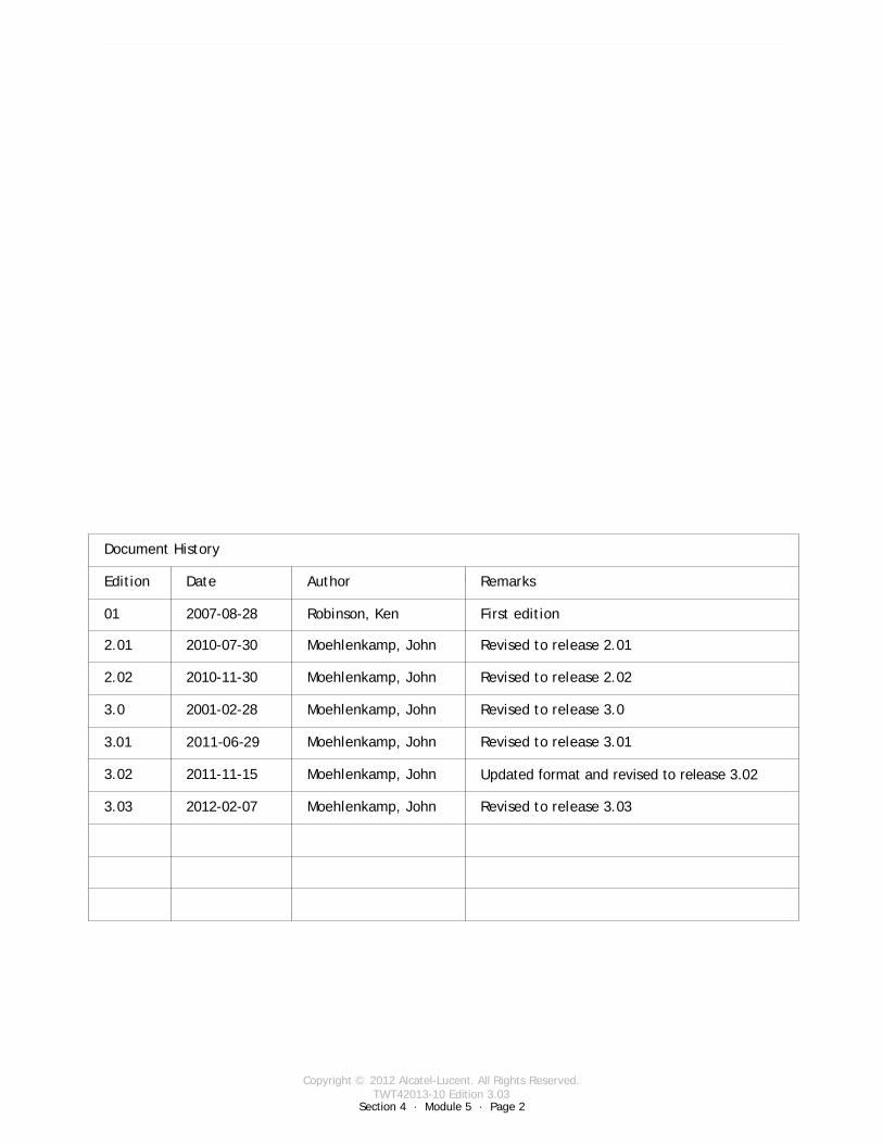
Copyright © 2012 Alcatel-Lucent. All Rights Reserved.TWT42013-10 Edition 3.03
Section 4 · Module 5 · Page 2
9500 MPR (Microwave Packet Radio) · Operations & Maintenance R3.03 (ANSI)NE Operation · Remove Cross Connections4 · 5 · 2
COPYRIGHT © ALCATEL-LUCENT 2012. ALL RIGHTS RESERVED.
Blank page
This page is left blank intentionally
Document History
Edition Date Author Remarks
01 2007-08-28 Robinson, Ken First edition
2.01 2010-07-30 Moehlenkamp, John Revised to release 2.01
2.02 2010-11-30 Moehlenkamp, John Revised to release 2.02
3.0 2001-02-28 Moehlenkamp, John Revised to release 3.0
3.01 2011-06-29 Moehlenkamp, John Revised to release 3.01
3.02 2011-11-15 Moehlenkamp, John Updated format and revised to release 3.02
3.03 2012-02-07 Moehlenkamp, John Revised to release 3.03

Copyright © 2012 Alcatel-Lucent. All Rights Reserved.TWT42013-10 Edition 3.03
Section 4 · Module 5 · Page 3
9500 MPR (Microwave Packet Radio) · Operations & Maintenance R3.03 (ANSI)NE Operation · Remove Cross Connections4 · 5 · 3
COPYRIGHT © ALCATEL-LUCENT 2012. ALL RIGHTS RESERVED.
Module objectives
Upon completion of this module, you should be able to:
Remove DS1 cross-connectionsRemove DS3 cross-connectionsRemove Ethernet cross-connectionsRemove radio cross-connections

Copyright © 2012 Alcatel-Lucent. All Rights Reserved.TWT42013-10 Edition 3.03
Section 4 · Module 5 · Page 4
9500 MPR (Microwave Packet Radio) · Operations & Maintenance R3.03 (ANSI)NE Operation · Remove Cross Connections4 · 5 · 4
COPYRIGHT © ALCATEL-LUCENT 2012. ALL RIGHTS RESERVED.
Module objectives [cont.]
This page is left blank intentionally

Copyright © 2012 Alcatel-Lucent. All Rights Reserved.TWT42013-10 Edition 3.03
9500 MPR (Microwave Packet Radio) · Operations & Maintenance R3.03 (ANSI)NE Operation · Remove Cross Connections4 · 5 · 5
COPYRIGHT © ALCATEL-LUCENT 2012. ALL RIGHTS RESERVED.
Table of Contents
Switch to notes view! Page
1 Removing DS1 Cross-Connections 71.1 Removing DS1 Cross-Connections 8
2 Removing DS3 Cross-Connections 152.1 Removing DS3 Cross-Connections 16
3 Removing Ethernet Cross-Connections 233.1 Removing Ethernet Cross-Connections 24
4 Removing Radio Cross-Connections 314.1 Removing Radio Cross-Connections 32

Copyright © 2012 Alcatel-Lucent. All Rights Reserved.TWT42013-10 Edition 3.03
9500 MPR (Microwave Packet Radio) · Operations & Maintenance R3.03 (ANSI)NE Operation · Remove Cross Connections4 · 5 · 6
COPYRIGHT © ALCATEL-LUCENT 2012. ALL RIGHTS RESERVED.
Table of Contents [cont.]
Switch to notes view!
This page is left blank intentionally

Copyright © 2012 Alcatel-Lucent. All Rights Reserved.TWT42013-10 Edition 3.03
Section 4 · Module 5 · Page 7Section 4 · Module 5 · Page 7
9500 MPR (Microwave Packet Radio) · Operations & Maintenance R3.03 (ANSI)NE Operation · Remove Cross Connections4 · 5 · 7
COPYRIGHT © ALCATEL-LUCENT 2012. ALL RIGHTS RESERVED.
1 Removing DS1 Cross-Connections
Refer to 9500 MPR Operation and Administration, 3EM23954AHAA, DLP-126 for more details
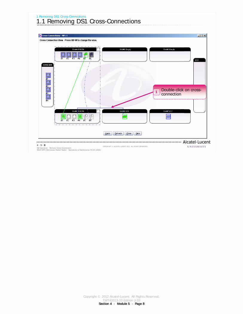
Copyright © 2012 Alcatel-Lucent. All Rights Reserved.TWT42013-10 Edition 3.03
Section 4 · Module 5 · Page 8Section 4 · Module 5 · Page 8
9500 MPR (Microwave Packet Radio) · Operations & Maintenance R3.03 (ANSI)NE Operation · Remove Cross Connections4 · 5 · 8
COPYRIGHT © ALCATEL-LUCENT 2012. ALL RIGHTS RESERVED.
1 Removing DS1 Cross-Connections
1.1 Removing DS1 Cross-Connections
Double-click on cross-connection1
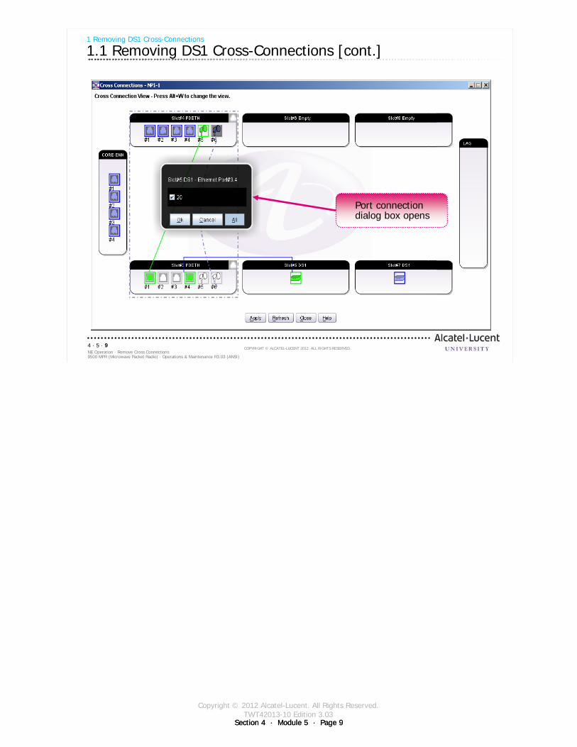
Copyright © 2012 Alcatel-Lucent. All Rights Reserved.TWT42013-10 Edition 3.03
Section 4 · Module 5 · Page 9Section 4 · Module 5 · Page 9
9500 MPR (Microwave Packet Radio) · Operations & Maintenance R3.03 (ANSI)NE Operation · Remove Cross Connections4 · 5 · 9
COPYRIGHT © ALCATEL-LUCENT 2012. ALL RIGHTS RESERVED.
1 Removing DS1 Cross-Connections
1.1 Removing DS1 Cross-Connections [cont.]
Port connection dialog box opens
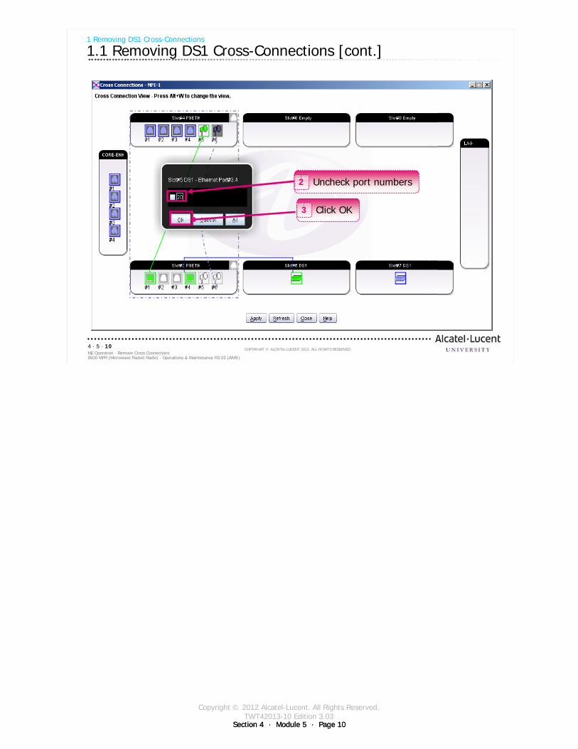
Copyright © 2012 Alcatel-Lucent. All Rights Reserved.TWT42013-10 Edition 3.03
Section 4 · Module 5 · Page 10Section 4 · Module 5 · Page 10
9500 MPR (Microwave Packet Radio) · Operations & Maintenance R3.03 (ANSI)NE Operation · Remove Cross Connections4 · 5 · 10
COPYRIGHT © ALCATEL-LUCENT 2012. ALL RIGHTS RESERVED.
1 Removing DS1 Cross-Connections
1.1 Removing DS1 Cross-Connections [cont.]
Uncheck port numbers2
Click OK3
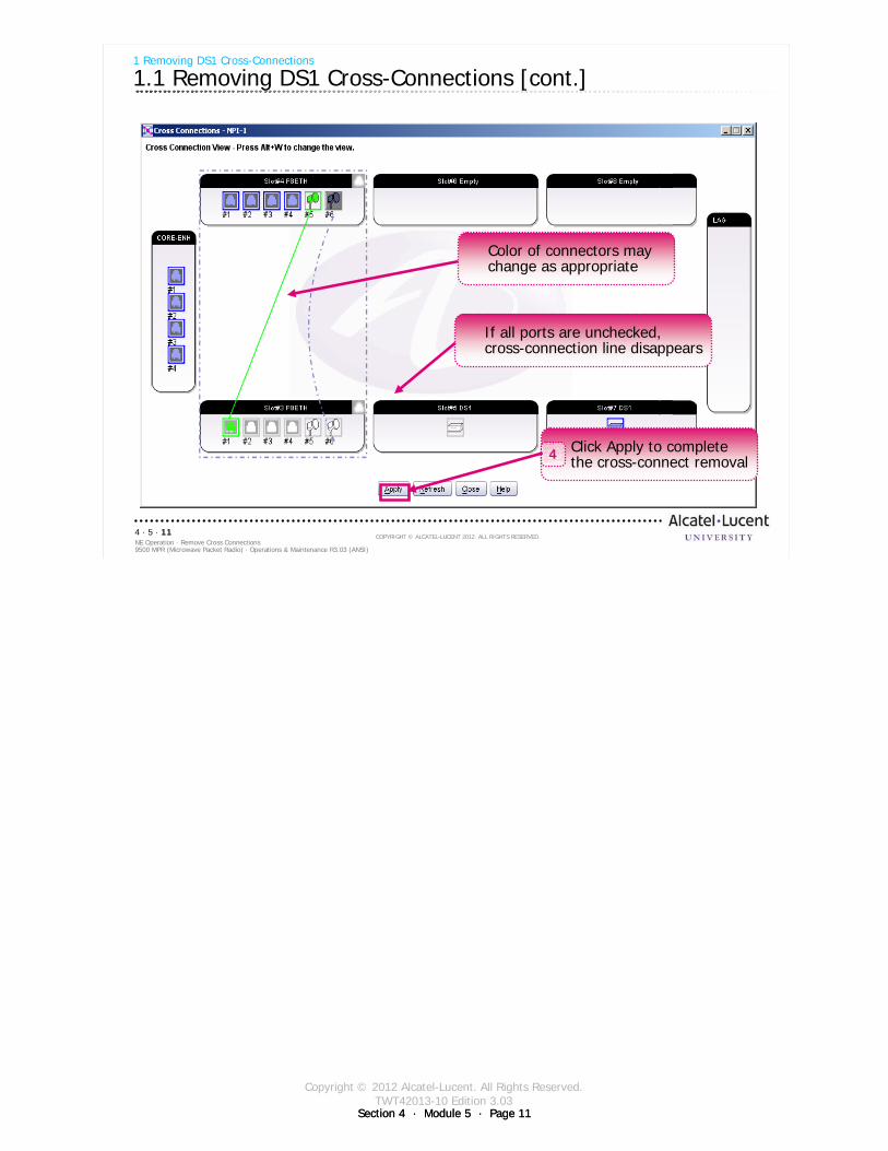
Copyright © 2012 Alcatel-Lucent. All Rights Reserved.TWT42013-10 Edition 3.03
Section 4 · Module 5 · Page 11Section 4 · Module 5 · Page 11
9500 MPR (Microwave Packet Radio) · Operations & Maintenance R3.03 (ANSI)NE Operation · Remove Cross Connections4 · 5 · 11
COPYRIGHT © ALCATEL-LUCENT 2012. ALL RIGHTS RESERVED.
1 Removing DS1 Cross-Connections
1.1 Removing DS1 Cross-Connections [cont.]
Color of connectors may change as appropriate
If all ports are unchecked, cross-connection line disappears
Click Apply to complete the cross-connect removal4

Copyright © 2012 Alcatel-Lucent. All Rights Reserved.TWT42013-10 Edition 3.03
Section 4 · Module 5 · Page 12Section 4 · Module 5 · Page 12
9500 MPR (Microwave Packet Radio) · Operations & Maintenance R3.03 (ANSI)NE Operation · Remove Cross Connections4 · 5 · 12
COPYRIGHT © ALCATEL-LUCENT 2012. ALL RIGHTS RESERVED.
Blank page
Switch to notes view!
This page intentionally left blank

Copyright © 2012 Alcatel-Lucent. All Rights Reserved.TWT42013-10 Edition 3.03
Section 4 · Module 5 · Page 13Section 4 · Module 5 · Page 13
9500 MPR (Microwave Packet Radio) · Operations & Maintenance R3.03 (ANSI)NE Operation · Remove Cross Connections4 · 5 · 13
COPYRIGHT © ALCATEL-LUCENT 2012. ALL RIGHTS RESERVED.
Exercise
Time allowed:
Lab Exercise 13Remove DS1 Cross-Connections

Copyright © 2012 Alcatel-Lucent. All Rights Reserved.TWT42013-10 Edition 3.03
Section 4 · Module 5 · Page 14Section 4 · Module 5 · Page 14
9500 MPR (Microwave Packet Radio) · Operations & Maintenance R3.03 (ANSI)NE Operation · Remove Cross Connections4 · 5 · 14
COPYRIGHT © ALCATEL-LUCENT 2012. ALL RIGHTS RESERVED.
Blank page
Switch to notes view!
This page intentionally left blank

Copyright © 2012 Alcatel-Lucent. All Rights Reserved.TWT42013-10 Edition 3.03
Section 4 · Module 5 · Page 15Section 4 · Module 5 · Page 15
9500 MPR (Microwave Packet Radio) · Operations & Maintenance R3.03 (ANSI)NE Operation · Remove Cross Connections4 · 5 · 15
COPYRIGHT © ALCATEL-LUCENT 2012. ALL RIGHTS RESERVED.
2 Removing DS3 Cross-Connections
Refer to 9500 MPR Operation and Administration, 3EM23954AHAA, DLP-126 for more details

Copyright © 2012 Alcatel-Lucent. All Rights Reserved.TWT42013-10 Edition 3.03
Section 4 · Module 5 · Page 16Section 4 · Module 5 · Page 16
9500 MPR (Microwave Packet Radio) · Operations & Maintenance R3.03 (ANSI)NE Operation · Remove Cross Connections4 · 5 · 16
COPYRIGHT © ALCATEL-LUCENT 2012. ALL RIGHTS RESERVED.
2 Removing DS3 Cross-Connections
2.1 Removing DS3 Cross-Connections
Double-click on cross-connection1

Copyright © 2012 Alcatel-Lucent. All Rights Reserved.TWT42013-10 Edition 3.03
Section 4 · Module 5 · Page 17Section 4 · Module 5 · Page 17
9500 MPR (Microwave Packet Radio) · Operations & Maintenance R3.03 (ANSI)NE Operation · Remove Cross Connections4 · 5 · 17
COPYRIGHT © ALCATEL-LUCENT 2012. ALL RIGHTS RESERVED.
2 Removing DS3 Cross-Connections
2.1 Removing DS3 Cross-Connections [cont.]
Port connection dialog box opens

Copyright © 2012 Alcatel-Lucent. All Rights Reserved.TWT42013-10 Edition 3.03
Section 4 · Module 5 · Page 18Section 4 · Module 5 · Page 18
9500 MPR (Microwave Packet Radio) · Operations & Maintenance R3.03 (ANSI)NE Operation · Remove Cross Connections4 · 5 · 18
COPYRIGHT © ALCATEL-LUCENT 2012. ALL RIGHTS RESERVED.
2 Removing DS3 Cross-Connections
2.1 Removing DS3 Cross-Connections [cont.]
Uncheck port numbers2
Click OK3
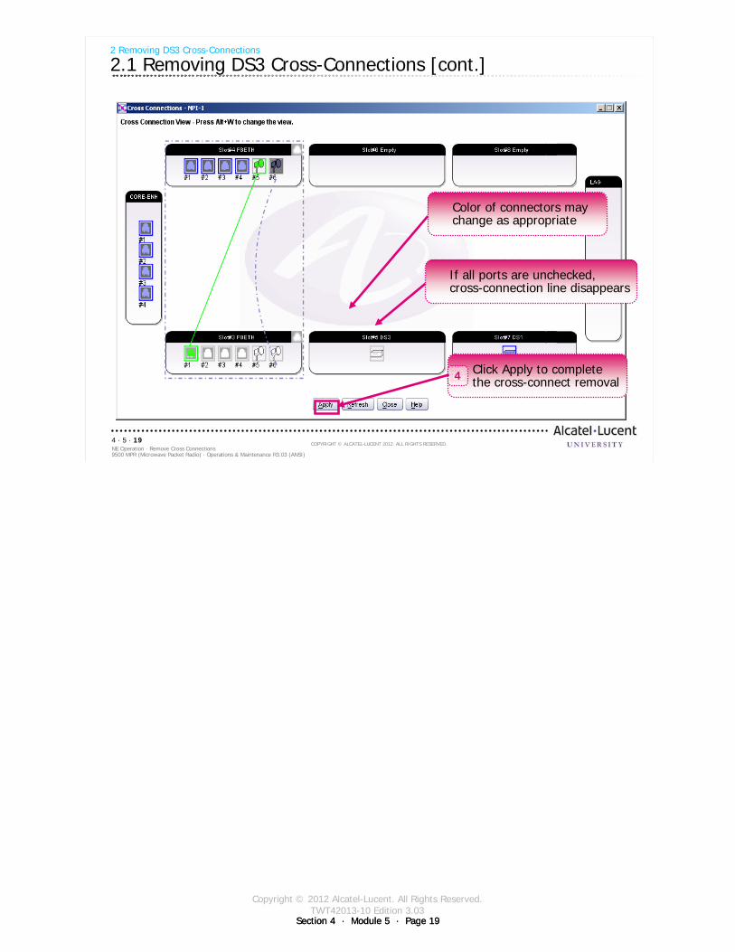
Copyright © 2012 Alcatel-Lucent. All Rights Reserved.TWT42013-10 Edition 3.03
Section 4 · Module 5 · Page 19Section 4 · Module 5 · Page 19
9500 MPR (Microwave Packet Radio) · Operations & Maintenance R3.03 (ANSI)NE Operation · Remove Cross Connections4 · 5 · 19
COPYRIGHT © ALCATEL-LUCENT 2012. ALL RIGHTS RESERVED.
2 Removing DS3 Cross-Connections
2.1 Removing DS3 Cross-Connections [cont.]
Color of connectors may change as appropriate
If all ports are unchecked, cross-connection line disappears
Click Apply to complete the cross-connect removal4

Copyright © 2012 Alcatel-Lucent. All Rights Reserved.TWT42013-10 Edition 3.03
Section 4 · Module 5 · Page 20Section 4 · Module 5 · Page 20
9500 MPR (Microwave Packet Radio) · Operations & Maintenance R3.03 (ANSI)NE Operation · Remove Cross Connections4 · 5 · 20
COPYRIGHT © ALCATEL-LUCENT 2012. ALL RIGHTS RESERVED.
Blank page
Switch to notes view!
This page intentionally left blank
Copyright © 2012 Alcatel-Lucent. All Rights Reserved.TWT42013-10 Edition 3.03
Section 4 · Module 5 · Page 21Section 4 · Module 5 · Page 21
9500 MPR (Microwave Packet Radio) · Operations & Maintenance R3.03 (ANSI)NE Operation · Remove Cross Connections4 · 5 · 21
COPYRIGHT © ALCATEL-LUCENT 2012. ALL RIGHTS RESERVED.
Exercise
Time allowed:
Lab Exercise 14Remove DS3 Cross-Connections

Copyright © 2012 Alcatel-Lucent. All Rights Reserved.TWT42013-10 Edition 3.03
Section 4 · Module 5 · Page 22Section 4 · Module 5 · Page 22
9500 MPR (Microwave Packet Radio) · Operations & Maintenance R3.03 (ANSI)NE Operation · Remove Cross Connections4 · 5 · 22
COPYRIGHT © ALCATEL-LUCENT 2012. ALL RIGHTS RESERVED.
Blank page
Switch to notes view!
This page intentionally left blank

Copyright © 2012 Alcatel-Lucent. All Rights Reserved.TWT42013-10 Edition 3.03
Section 4 · Module 5 · Page 23Section 4 · Module 5 · Page 23
9500 MPR (Microwave Packet Radio) · Operations & Maintenance R3.03 (ANSI)NE Operation · Remove Cross Connections4 · 5 · 23
COPYRIGHT © ALCATEL-LUCENT 2012. ALL RIGHTS RESERVED.
3 Removing Ethernet Cross-Connections
Refer to 9500 MPR Operation and Administration, 3EM23954AHAA, DLP-126 for more details
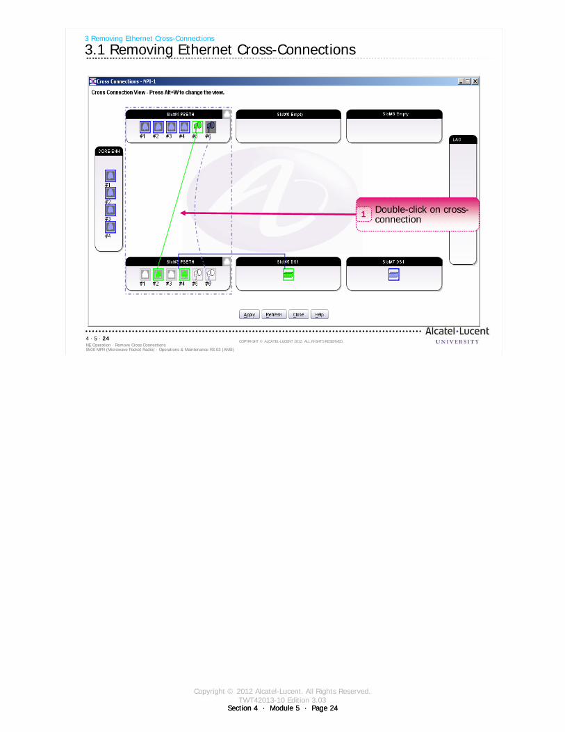
Copyright © 2012 Alcatel-Lucent. All Rights Reserved.TWT42013-10 Edition 3.03
Section 4 · Module 5 · Page 24Section 4 · Module 5 · Page 24
9500 MPR (Microwave Packet Radio) · Operations & Maintenance R3.03 (ANSI)NE Operation · Remove Cross Connections4 · 5 · 24
COPYRIGHT © ALCATEL-LUCENT 2012. ALL RIGHTS RESERVED.
3 Removing Ethernet Cross-Connections
3.1 Removing Ethernet Cross-Connections
Double-click on cross-connection1
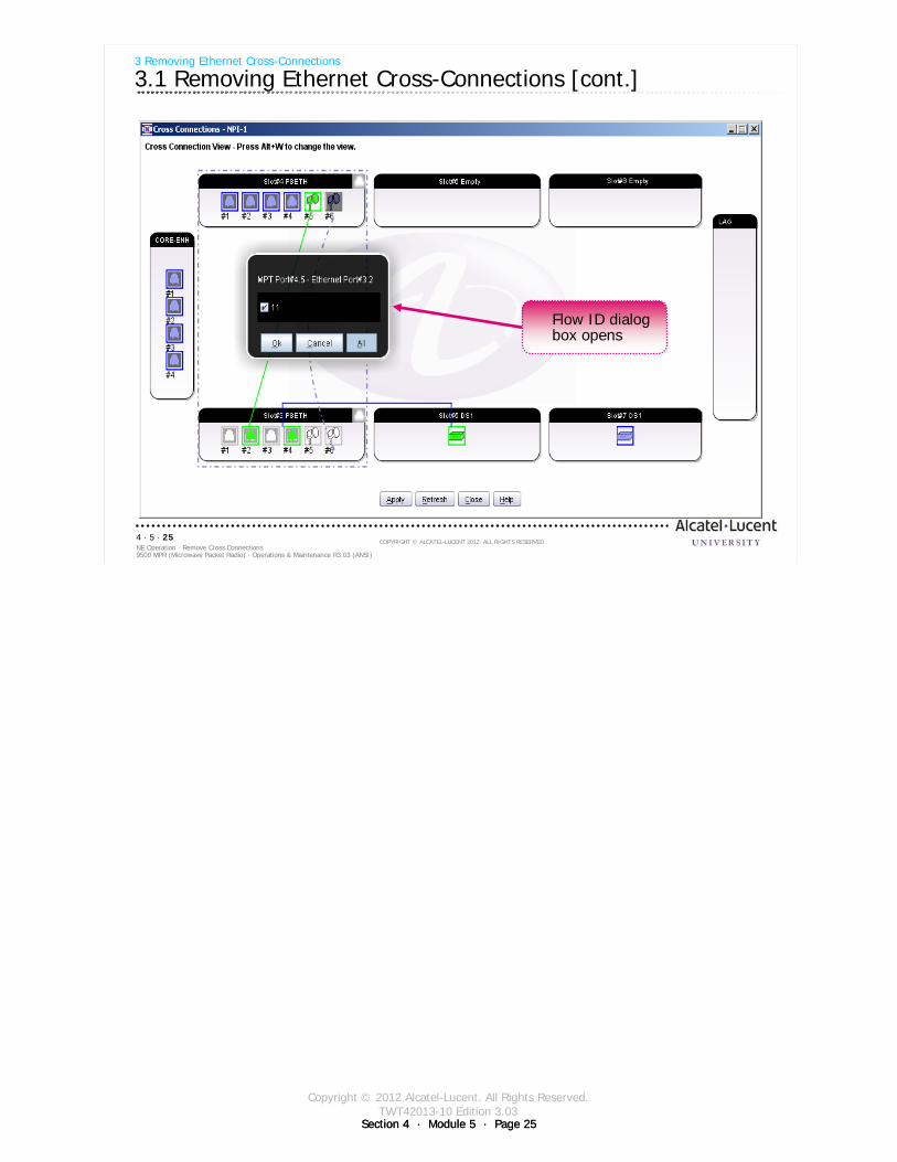
Copyright © 2012 Alcatel-Lucent. All Rights Reserved.TWT42013-10 Edition 3.03
Section 4 · Module 5 · Page 25Section 4 · Module 5 · Page 25
9500 MPR (Microwave Packet Radio) · Operations & Maintenance R3.03 (ANSI)NE Operation · Remove Cross Connections4 · 5 · 25
COPYRIGHT © ALCATEL-LUCENT 2012. ALL RIGHTS RESERVED.
3 Removing Ethernet Cross-Connections
3.1 Removing Ethernet Cross-Connections [cont.]
Flow ID dialog box opens
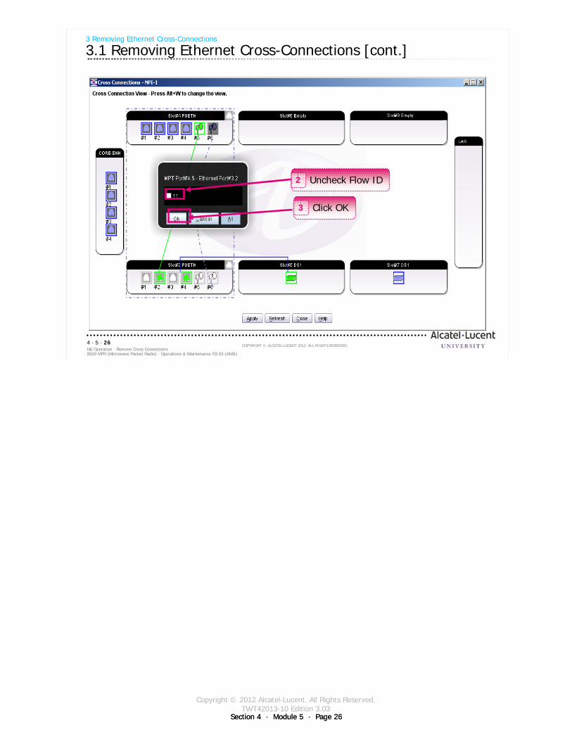
Copyright © 2012 Alcatel-Lucent. All Rights Reserved.TWT42013-10 Edition 3.03
Section 4 · Module 5 · Page 26Section 4 · Module 5 · Page 26
9500 MPR (Microwave Packet Radio) · Operations & Maintenance R3.03 (ANSI)NE Operation · Remove Cross Connections4 · 5 · 26
COPYRIGHT © ALCATEL-LUCENT 2012. ALL RIGHTS RESERVED.
3 Removing Ethernet Cross-Connections
3.1 Removing Ethernet Cross-Connections [cont.]
Uncheck Flow ID2
Click OK3
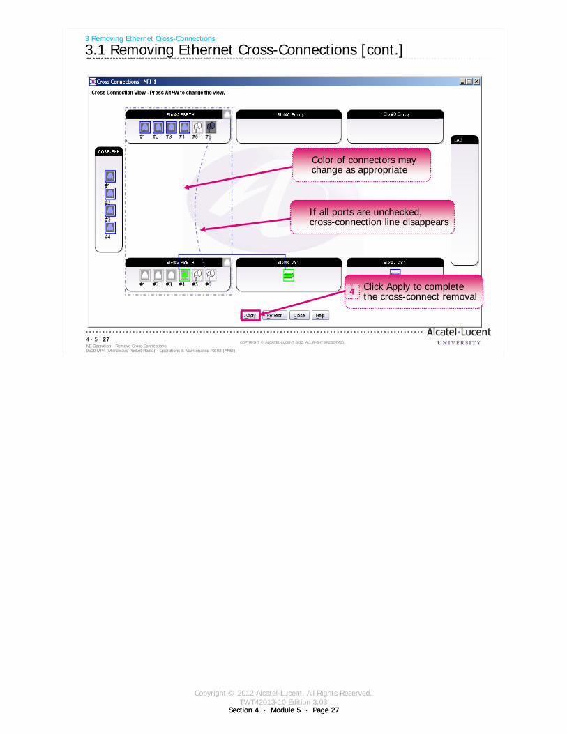
Copyright © 2012 Alcatel-Lucent. All Rights Reserved.TWT42013-10 Edition 3.03
Section 4 · Module 5 · Page 27Section 4 · Module 5 · Page 27
9500 MPR (Microwave Packet Radio) · Operations & Maintenance R3.03 (ANSI)NE Operation · Remove Cross Connections4 · 5 · 27
COPYRIGHT © ALCATEL-LUCENT 2012. ALL RIGHTS RESERVED.
3 Removing Ethernet Cross-Connections
3.1 Removing Ethernet Cross-Connections [cont.]
Color of connectors may change as appropriate
If all ports are unchecked, cross-connection line disappears
Click Apply to complete the cross-connect removal4

Copyright © 2012 Alcatel-Lucent. All Rights Reserved.TWT42013-10 Edition 3.03
Section 4 · Module 5 · Page 28Section 4 · Module 5 · Page 28
9500 MPR (Microwave Packet Radio) · Operations & Maintenance R3.03 (ANSI)NE Operation · Remove Cross Connections4 · 5 · 28
COPYRIGHT © ALCATEL-LUCENT 2012. ALL RIGHTS RESERVED.
Blank page
Switch to notes view!
This page intentionally left blank

Copyright © 2012 Alcatel-Lucent. All Rights Reserved.TWT42013-10 Edition 3.03
Section 4 · Module 5 · Page 29Section 4 · Module 5 · Page 29
9500 MPR (Microwave Packet Radio) · Operations & Maintenance R3.03 (ANSI)NE Operation · Remove Cross Connections4 · 5 · 29
COPYRIGHT © ALCATEL-LUCENT 2012. ALL RIGHTS RESERVED.
Exercise
Time allowed:
Lab Exercise 15Remove Ethernet Cross-Connections

Copyright © 2012 Alcatel-Lucent. All Rights Reserved.TWT42013-10 Edition 3.03
Section 4 · Module 5 · Page 30Section 4 · Module 5 · Page 30
9500 MPR (Microwave Packet Radio) · Operations & Maintenance R3.03 (ANSI)NE Operation · Remove Cross Connections4 · 5 · 30
COPYRIGHT © ALCATEL-LUCENT 2012. ALL RIGHTS RESERVED.
Blank page
Switch to notes view!
This page intentionally left blank
Copyright © 2012 Alcatel-Lucent. All Rights Reserved.TWT42013-10 Edition 3.03
Section 4 · Module 5 · Page 31Section 4 · Module 5 · Page 31
9500 MPR (Microwave Packet Radio) · Operations & Maintenance R3.03 (ANSI)NE Operation · Remove Cross Connections4 · 5 · 31
COPYRIGHT © ALCATEL-LUCENT 2012. ALL RIGHTS RESERVED.
4 Removing Radio Cross-Connections
Refer to 9500 MPR Operation and Administration, 3EM23954AHAA, DLP-126 for more details
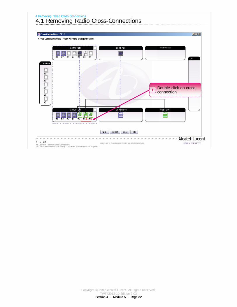
Copyright © 2012 Alcatel-Lucent. All Rights Reserved.TWT42013-10 Edition 3.03
Section 4 · Module 5 · Page 32Section 4 · Module 5 · Page 32
9500 MPR (Microwave Packet Radio) · Operations & Maintenance R3.03 (ANSI)NE Operation · Remove Cross Connections4 · 5 · 32
COPYRIGHT © ALCATEL-LUCENT 2012. ALL RIGHTS RESERVED.
4 Removing Radio Cross-Connections
4.1 Removing Radio Cross-Connections
Double-click on cross-connection1
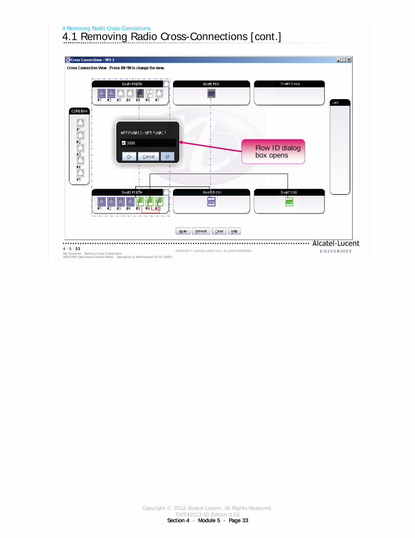
Copyright © 2012 Alcatel-Lucent. All Rights Reserved.TWT42013-10 Edition 3.03
Section 4 · Module 5 · Page 33Section 4 · Module 5 · Page 33
9500 MPR (Microwave Packet Radio) · Operations & Maintenance R3.03 (ANSI)NE Operation · Remove Cross Connections4 · 5 · 33
COPYRIGHT © ALCATEL-LUCENT 2012. ALL RIGHTS RESERVED.
4 Removing Radio Cross-Connections
4.1 Removing Radio Cross-Connections [cont.]
Flow ID dialog box opens
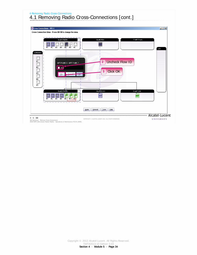
Copyright © 2012 Alcatel-Lucent. All Rights Reserved.TWT42013-10 Edition 3.03
Section 4 · Module 5 · Page 34Section 4 · Module 5 · Page 34
9500 MPR (Microwave Packet Radio) · Operations & Maintenance R3.03 (ANSI)NE Operation · Remove Cross Connections4 · 5 · 34
COPYRIGHT © ALCATEL-LUCENT 2012. ALL RIGHTS RESERVED.
4 Removing Radio Cross-Connections
4.1 Removing Radio Cross-Connections [cont.]
Uncheck Flow ID2
Click OK3

Copyright © 2012 Alcatel-Lucent. All Rights Reserved.TWT42013-10 Edition 3.03
Section 4 · Module 5 · Page 35Section 4 · Module 5 · Page 35
9500 MPR (Microwave Packet Radio) · Operations & Maintenance R3.03 (ANSI)NE Operation · Remove Cross Connections4 · 5 · 35
COPYRIGHT © ALCATEL-LUCENT 2012. ALL RIGHTS RESERVED.
4 Removing Radio Cross-Connections
4.1 Removing Radio Cross-Connections [cont.]
Color of connectors may change as appropriate
If all ports are unchecked, cross-connection line disappears
Click Apply to complete the cross-connect removal4

Copyright © 2012 Alcatel-Lucent. All Rights Reserved.TWT42013-10 Edition 3.03
Section 4 · Module 5 · Page 36Section 4 · Module 5 · Page 36
9500 MPR (Microwave Packet Radio) · Operations & Maintenance R3.03 (ANSI)NE Operation · Remove Cross Connections4 · 5 · 36
COPYRIGHT © ALCATEL-LUCENT 2012. ALL RIGHTS RESERVED.
Blank page
Switch to notes view!
This page intentionally left blank

Copyright © 2012 Alcatel-Lucent. All Rights Reserved.TWT42013-10 Edition 3.03
Section 4 · Module 5 · Page 37Section 4 · Module 5 · Page 37
9500 MPR (Microwave Packet Radio) · Operations & Maintenance R3.03 (ANSI)NE Operation · Remove Cross Connections4 · 5 · 37
COPYRIGHT © ALCATEL-LUCENT 2012. ALL RIGHTS RESERVED.
Exercise
Time allowed:
Lab Exercise 16Remove Radio Cross-Connections

Copyright © 2012 Alcatel-Lucent. All Rights Reserved.TWT42013-10 Edition 3.03
Section 4 · Module 5 · Page 38Section 4 · Module 5 · Page 38
9500 MPR (Microwave Packet Radio) · Operations & Maintenance R3.03 (ANSI)NE Operation · Remove Cross Connections4 · 5 · 38
COPYRIGHT © ALCATEL-LUCENT 2012. ALL RIGHTS RESERVED.
Blank page
Switch to notes view!
This page intentionally left blank
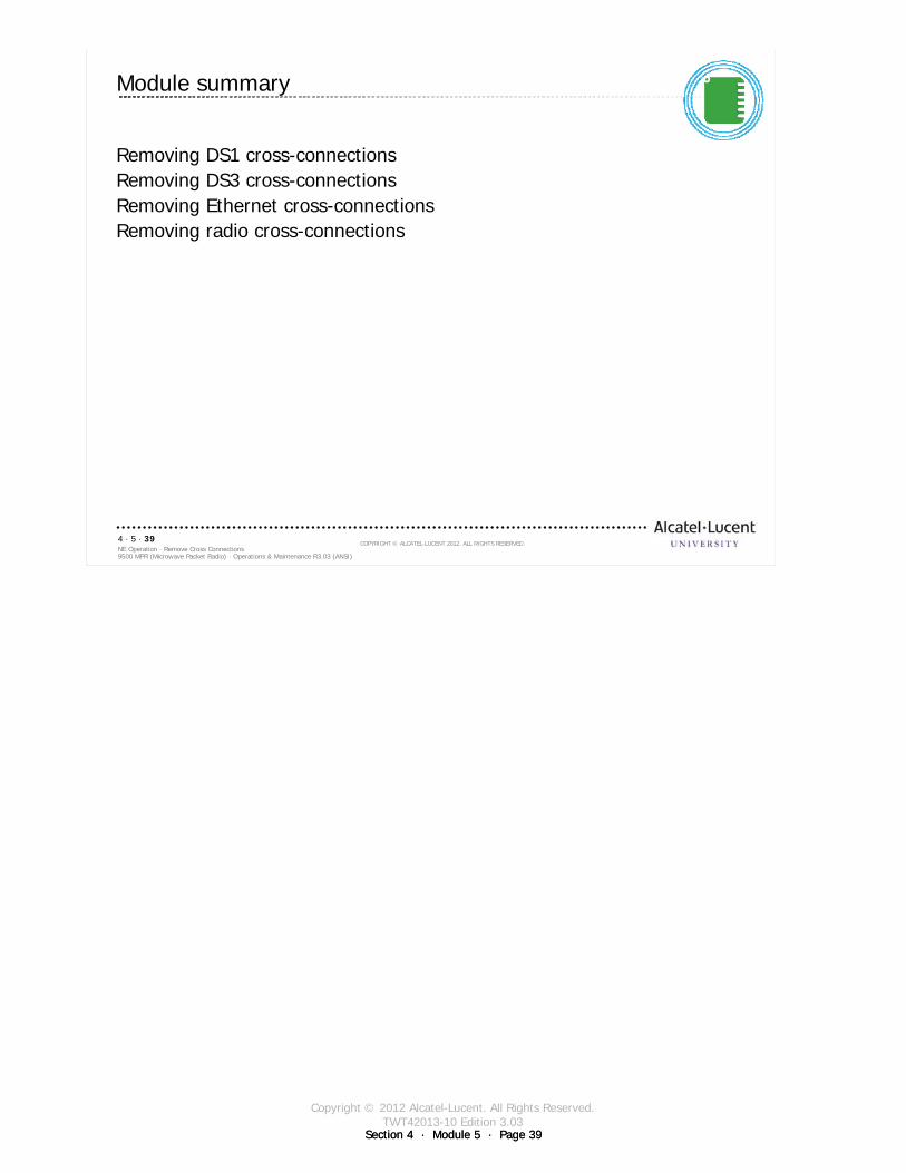
Copyright © 2012 Alcatel-Lucent. All Rights Reserved.TWT42013-10 Edition 3.03
Section 4 · Module 5 · Page 39Section 4 · Module 5 · Page 39
9500 MPR (Microwave Packet Radio) · Operations & Maintenance R3.03 (ANSI)NE Operation · Remove Cross Connections4 · 5 · 39
COPYRIGHT © ALCATEL-LUCENT 2012. ALL RIGHTS RESERVED.
Module summary
Removing DS1 cross-connectionsRemoving DS3 cross-connectionsRemoving Ethernet cross-connectionsRemoving radio cross-connections

Copyright © 2012 Alcatel-Lucent. All Rights Reserved.TWT42013-10 Edition 3.03
Section 4 · Module 5 · Page 40Section 4 · Module 5 · Page 40
9500 MPR (Microwave Packet Radio) · Operations & Maintenance R3.03 (ANSI)NE Operation · Remove Cross Connections4 · 5 · 40
COPYRIGHT © ALCATEL-LUCENT 2012. ALL RIGHTS RESERVED.
End of moduleRemove Cross Connections

Copyright © 2012 Alcatel-Lucent. All Rights Reserved.TWT42013-11 Edition 3.03
Section 4 · Module 6 · Page 1
Do not delete this graphic elements in here:
All Rights Reserved © Alcatel-Lucent @@YEAR
Module 6Browser Interface
TWT42013-11 Edition 3.03
Section 4NE Operation
9500 MPR (Microwave Packet Radio)Operations & Maintenance R3.03 (ANSI)
TWT42013 Edition 1.1
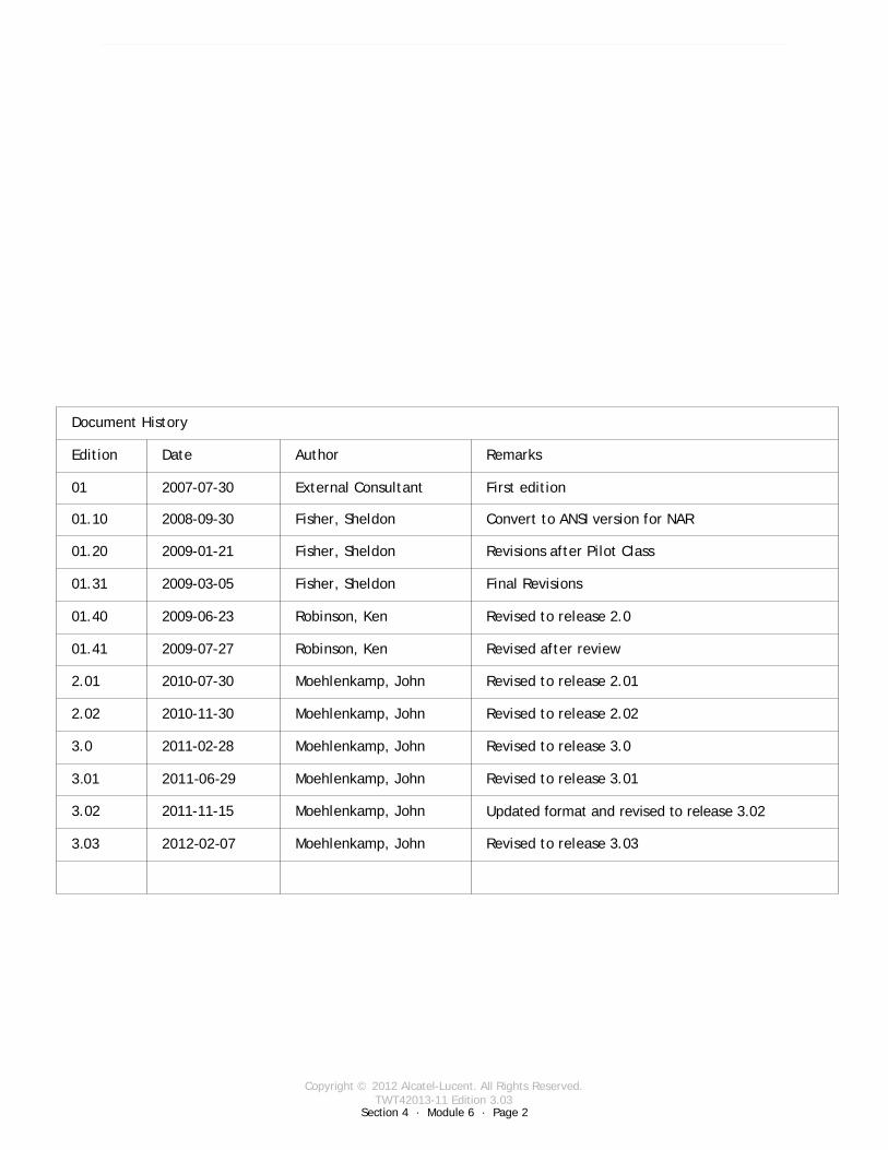
Copyright © 2012 Alcatel-Lucent. All Rights Reserved.TWT42013-11 Edition 3.03
Section 4 · Module 6 · Page 2
9500 MPR (Microwave Packet Radio) · Operations & Maintenance R3.03 (ANSI)NE Operation · Browser Interface4 · 6 · 2
COPYRIGHT © ALCATEL-LUCENT 2012. ALL RIGHTS RESERVED.
Blank page
This page is left blank intentionally
Revised to release 3.03Moehlenkamp, John2012-02-073.03
Document History
Edition Date Author Remarks
01 2007-07-30 External Consultant First edition
01.10 2008-09-30 Fisher, Sheldon Convert to ANSI version for NAR
01.20 2009-01-21 Fisher, Sheldon Revisions after Pilot Class
01.31 2009-03-05 Fisher, Sheldon Final Revisions
01.40 2009-06-23 Robinson, Ken Revised to release 2.0
01.41 2009-07-27 Robinson, Ken Revised after review
2.01 2010-07-30 Moehlenkamp, John Revised to release 2.01
2.02 2010-11-30 Moehlenkamp, John Revised to release 2.02
3.0 2011-02-28 Moehlenkamp, John Revised to release 3.0
3.01 2011-06-29 Moehlenkamp, John Revised to release 3.01
3.02 2011-11-15 Moehlenkamp, John Updated format and revised to release 3.02
Copyright © 2012 Alcatel-Lucent. All Rights Reserved.TWT42013-11 Edition 3.03
Section 4 · Module 6 · Page 3
9500 MPR (Microwave Packet Radio) · Operations & Maintenance R3.03 (ANSI)NE Operation · Browser Interface4 · 6 · 3
COPYRIGHT © ALCATEL-LUCENT 2012. ALL RIGHTS RESERVED.
Module objectives
Upon completion of this module, you should be able to connect to a 9500 MPR-A using a Web browser:
Check Date and Time SettingsPrint Configuration InformationLicense InformationCheck DHCP status

Copyright © 2012 Alcatel-Lucent. All Rights Reserved.TWT42013-11 Edition 3.03
Section 4 · Module 6 · Page 4
9500 MPR (Microwave Packet Radio) · Operations & Maintenance R3.03 (ANSI)NE Operation · Browser Interface4 · 6 · 4
COPYRIGHT © ALCATEL-LUCENT 2012. ALL RIGHTS RESERVED.
Module objectives [cont.]
This page is left blank intentionally
Copyright © 2012 Alcatel-Lucent. All Rights Reserved.TWT42013-11 Edition 3.03
9500 MPR (Microwave Packet Radio) · Operations & Maintenance R3.03 (ANSI)NE Operation · Browser Interface4 · 6 · 5
COPYRIGHT © ALCATEL-LUCENT 2012. ALL RIGHTS RESERVED.
Table of Contents
Switch to notes view! Page
1 Browser Interface 71.1 Browser Interface 81.2 Browser Interface - Logon 91.3 Browser Interface - Alarm Screen 101.4 Browser Interface - Date & Time Setting 111.5 Browser Interface - Date & Time NTP Enabled 121.6 Browser Interface - Configuration Info 131.7 Browser Interface - DHCP 151.8 Browser Interface - License Info 161.9 Community Strings Setting 171.10 Browser Interface - Logout 18

Copyright © 2012 Alcatel-Lucent. All Rights Reserved.TWT42013-11 Edition 3.03
9500 MPR (Microwave Packet Radio) · Operations & Maintenance R3.03 (ANSI)NE Operation · Browser Interface4 · 6 · 6
COPYRIGHT © ALCATEL-LUCENT 2012. ALL RIGHTS RESERVED.
Table of Contents [cont.]
Switch to notes view!
This page is left blank intentionally

Copyright © 2012 Alcatel-Lucent. All Rights Reserved.TWT42013-11 Edition 3.03
Section 4 · Module 6 · Page 7Section 4 · Module 6 · Page 7
9500 MPR (Microwave Packet Radio) · Operations & Maintenance R3.03 (ANSI)NE Operation · Browser Interface4 · 6 · 7
COPYRIGHT © ALCATEL-LUCENT 2012. ALL RIGHTS RESERVED.
1 Browser Interface
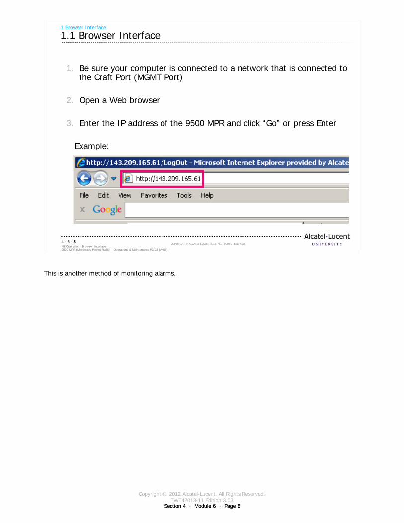
Copyright © 2012 Alcatel-Lucent. All Rights Reserved.TWT42013-11 Edition 3.03
Section 4 · Module 6 · Page 8Section 4 · Module 6 · Page 8
9500 MPR (Microwave Packet Radio) · Operations & Maintenance R3.03 (ANSI)NE Operation · Browser Interface4 · 6 · 8
COPYRIGHT © ALCATEL-LUCENT 2012. ALL RIGHTS RESERVED.
1. Be sure your computer is connected to a network that is connected to the Craft Port (MGMT Port)
2. Open a Web browser
3. Enter the IP address of the 9500 MPR and click “Go” or press Enter
Example:
1 Browser Interface
1.1 Browser Interface
This is another method of monitoring alarms.
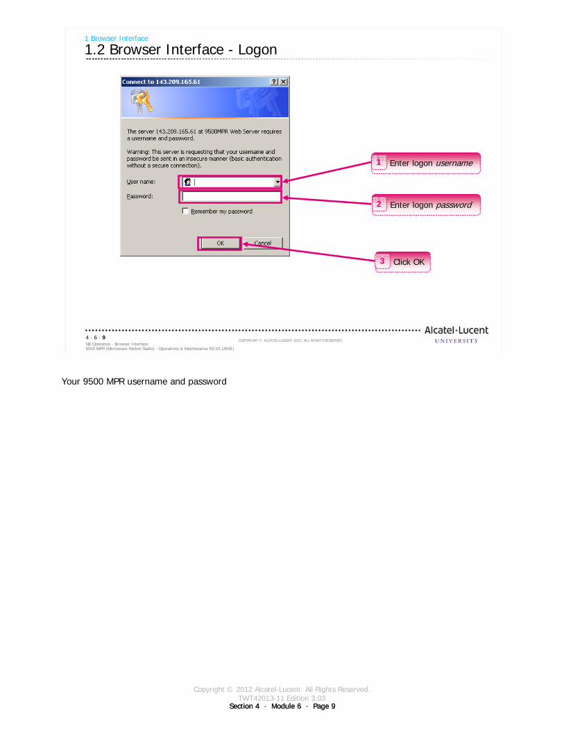
Copyright © 2012 Alcatel-Lucent. All Rights Reserved.TWT42013-11 Edition 3.03
Section 4 · Module 6 · Page 9Section 4 · Module 6 · Page 9
9500 MPR (Microwave Packet Radio) · Operations & Maintenance R3.03 (ANSI)NE Operation · Browser Interface4 · 6 · 9
COPYRIGHT © ALCATEL-LUCENT 2012. ALL RIGHTS RESERVED.
1 Browser Interface
1.2 Browser Interface - Logon
Enter logon username1
Enter logon password2
Click OK3
Your 9500 MPR username and password
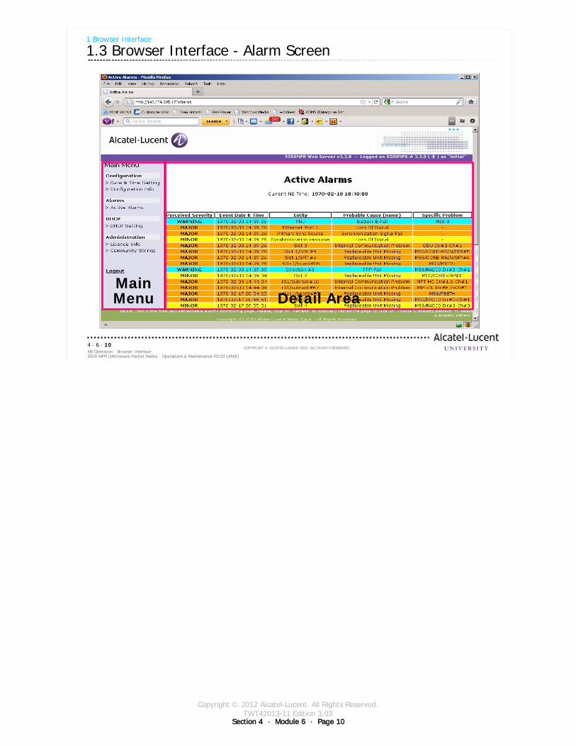
Copyright © 2012 Alcatel-Lucent. All Rights Reserved.TWT42013-11 Edition 3.03
Section 4 · Module 6 · Page 10Section 4 · Module 6 · Page 10
9500 MPR (Microwave Packet Radio) · Operations & Maintenance R3.03 (ANSI)NE Operation · Browser Interface4 · 6 · 10
COPYRIGHT © ALCATEL-LUCENT 2012. ALL RIGHTS RESERVED.
1 Browser Interface
1.3 Browser Interface - Alarm Screen
MainMenu Detail Area
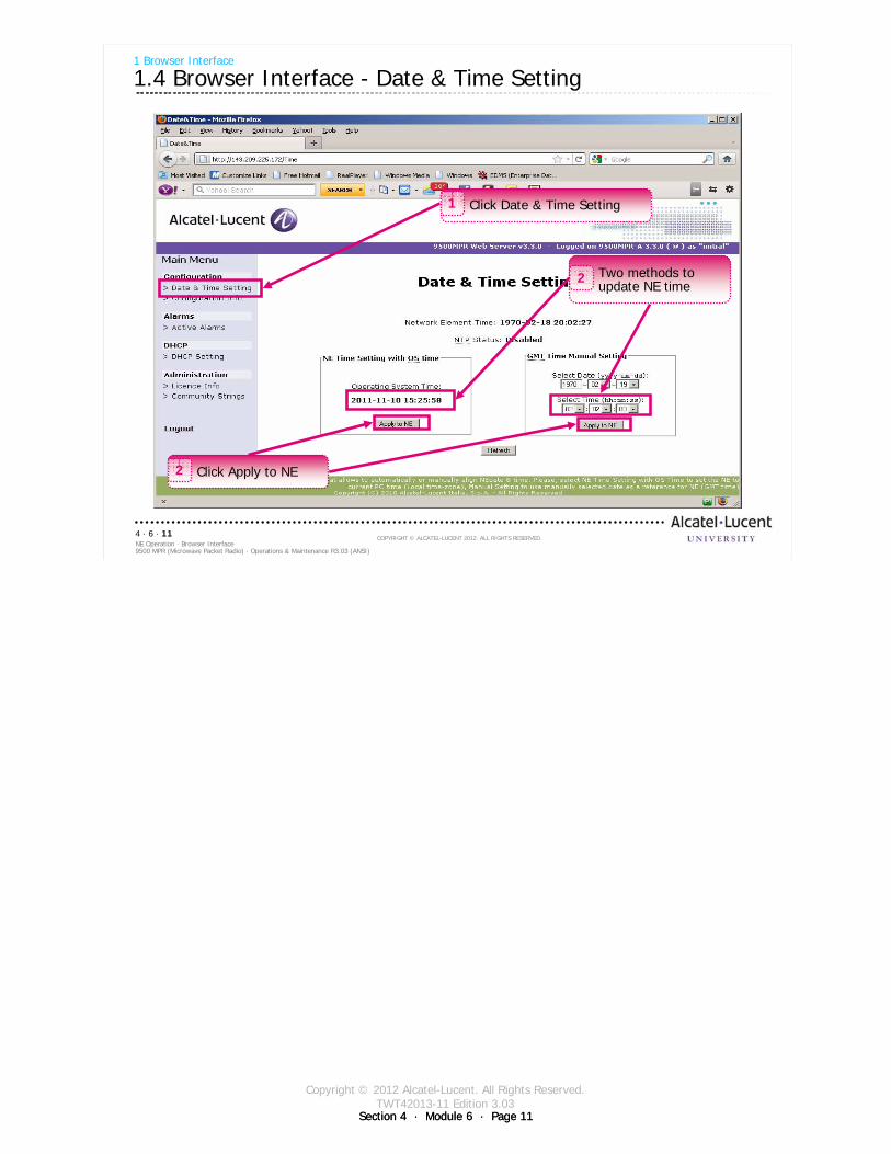
Copyright © 2012 Alcatel-Lucent. All Rights Reserved.TWT42013-11 Edition 3.03
Section 4 · Module 6 · Page 11Section 4 · Module 6 · Page 11
9500 MPR (Microwave Packet Radio) · Operations & Maintenance R3.03 (ANSI)NE Operation · Browser Interface4 · 6 · 11
COPYRIGHT © ALCATEL-LUCENT 2012. ALL RIGHTS RESERVED.
1 Browser Interface
1.4 Browser Interface - Date & Time Setting
Click Date & Time Setting1
Two methods to update NE time
2
Click Apply to NE2
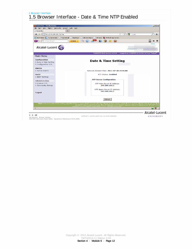
Copyright © 2012 Alcatel-Lucent. All Rights Reserved.TWT42013-11 Edition 3.03
Section 4 · Module 6 · Page 12Section 4 · Module 6 · Page 12
9500 MPR (Microwave Packet Radio) · Operations & Maintenance R3.03 (ANSI)NE Operation · Browser Interface4 · 6 · 12
COPYRIGHT © ALCATEL-LUCENT 2012. ALL RIGHTS RESERVED.
1 Browser Interface
1.5 Browser Interface - Date & Time NTP Enabled
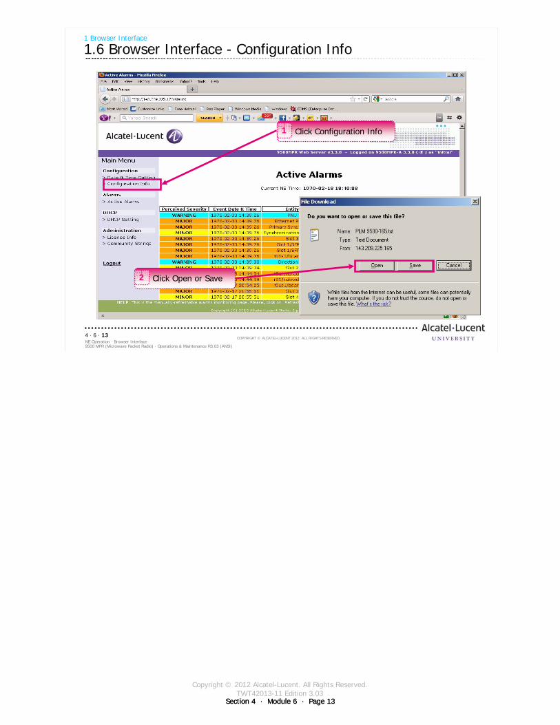
Copyright © 2012 Alcatel-Lucent. All Rights Reserved.TWT42013-11 Edition 3.03
Section 4 · Module 6 · Page 13Section 4 · Module 6 · Page 13
9500 MPR (Microwave Packet Radio) · Operations & Maintenance R3.03 (ANSI)NE Operation · Browser Interface4 · 6 · 13
COPYRIGHT © ALCATEL-LUCENT 2012. ALL RIGHTS RESERVED.
1 Browser Interface
1.6 Browser Interface - Configuration Info
Click Configuration Info1
Click Open or Save2
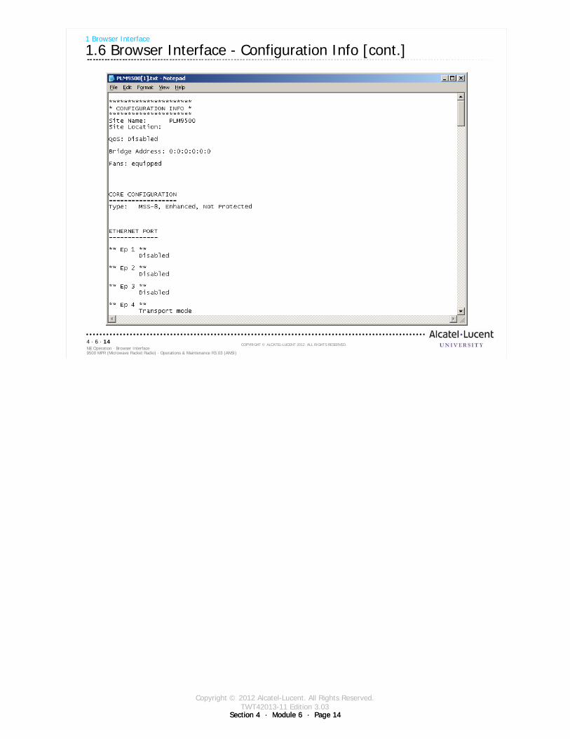
Copyright © 2012 Alcatel-Lucent. All Rights Reserved.TWT42013-11 Edition 3.03
Section 4 · Module 6 · Page 14Section 4 · Module 6 · Page 14
9500 MPR (Microwave Packet Radio) · Operations & Maintenance R3.03 (ANSI)NE Operation · Browser Interface4 · 6 · 14
COPYRIGHT © ALCATEL-LUCENT 2012. ALL RIGHTS RESERVED.
1 Browser Interface
1.6 Browser Interface - Configuration Info [cont.]
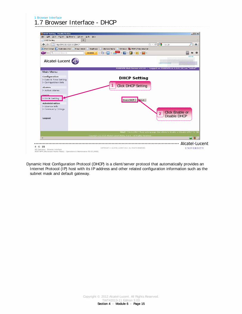
Copyright © 2012 Alcatel-Lucent. All Rights Reserved.TWT42013-11 Edition 3.03
Section 4 · Module 6 · Page 15Section 4 · Module 6 · Page 15
9500 MPR (Microwave Packet Radio) · Operations & Maintenance R3.03 (ANSI)NE Operation · Browser Interface4 · 6 · 15
COPYRIGHT © ALCATEL-LUCENT 2012. ALL RIGHTS RESERVED.
1 Browser Interface
1.7 Browser Interface - DHCP
Click DHCP Setting1
Click Enable or Disable DHCP
2
Dynamic Host Configuration Protocol (DHCP) is a client/server protocol that automatically provides an Internet Protocol (IP) host with its IP address and other related configuration information such as the subnet mask and default gateway.
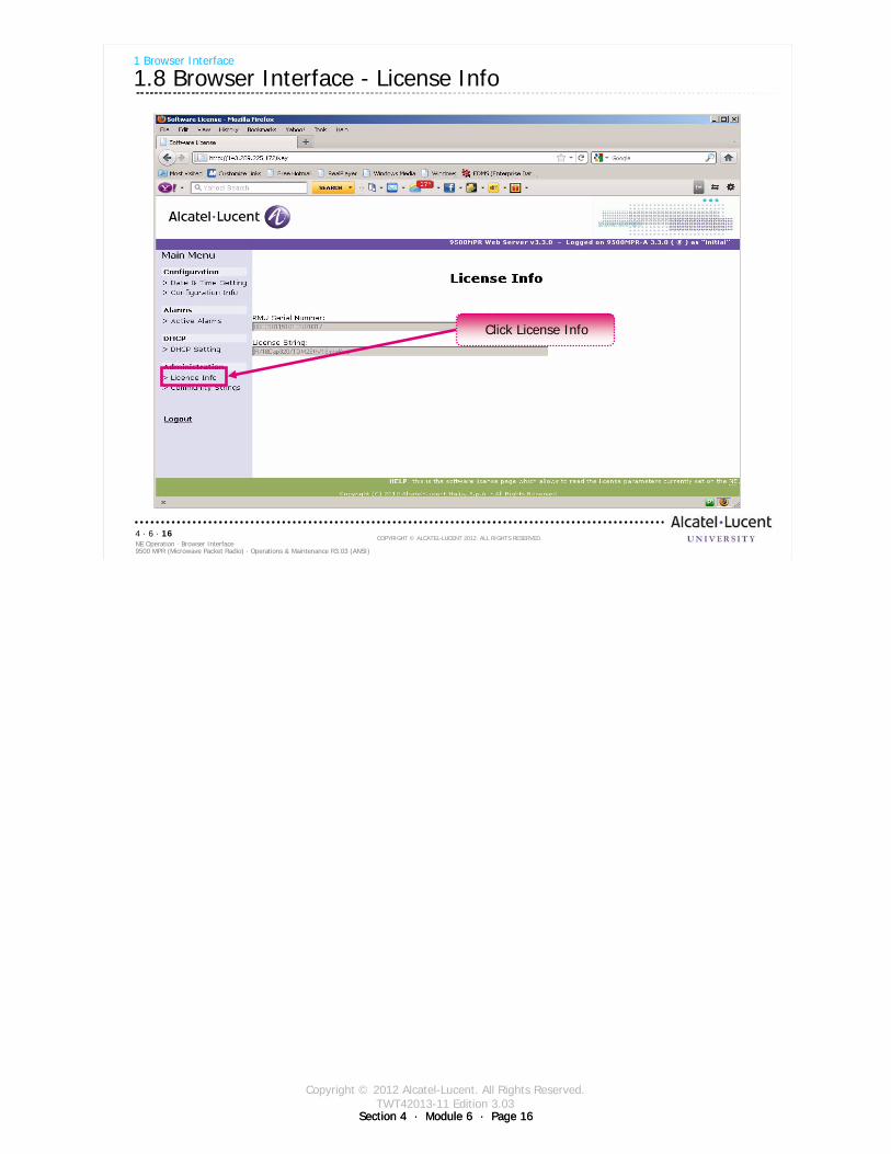
Copyright © 2012 Alcatel-Lucent. All Rights Reserved.TWT42013-11 Edition 3.03
Section 4 · Module 6 · Page 16Section 4 · Module 6 · Page 16
9500 MPR (Microwave Packet Radio) · Operations & Maintenance R3.03 (ANSI)NE Operation · Browser Interface4 · 6 · 16
COPYRIGHT © ALCATEL-LUCENT 2012. ALL RIGHTS RESERVED.
1 Browser Interface
1.8 Browser Interface - License Info
Click License Info
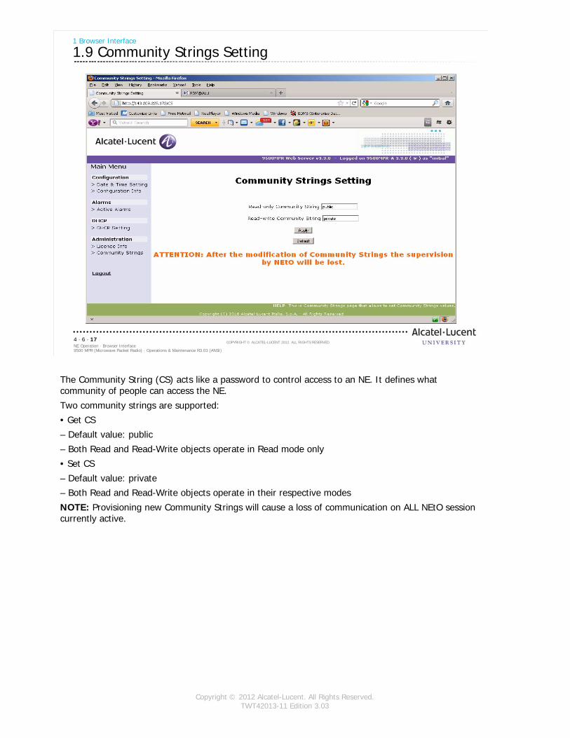
Copyright © 2012 Alcatel-Lucent. All Rights Reserved.TWT42013-11 Edition 3.03
9500 MPR (Microwave Packet Radio) · Operations & Maintenance R3.03 (ANSI)NE Operation · Browser Interface4 · 6 · 17
COPYRIGHT © ALCATEL-LUCENT 2012. ALL RIGHTS RESERVED.
1 Browser Interface
1.9 Community Strings Setting
The Community String (CS) acts like a password to control access to an NE. It defines what community of people can access the NE.
Two community strings are supported:
• Get CS
– Default value: public
– Both Read and Read-Write objects operate in Read mode only
• Set CS
– Default value: private
– Both Read and Read-Write objects operate in their respective modes
NOTE: Provisioning new Community Strings will cause a loss of communication on ALL NEtO session currently active.
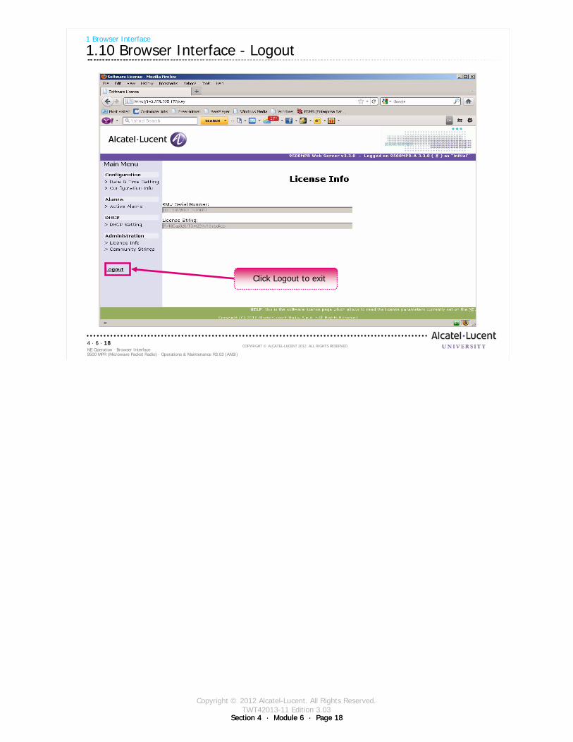
Copyright © 2012 Alcatel-Lucent. All Rights Reserved.TWT42013-11 Edition 3.03
Section 4 · Module 6 · Page 18Section 4 · Module 6 · Page 18
9500 MPR (Microwave Packet Radio) · Operations & Maintenance R3.03 (ANSI)NE Operation · Browser Interface4 · 6 · 18
COPYRIGHT © ALCATEL-LUCENT 2012. ALL RIGHTS RESERVED.
1 Browser Interface
1.10 Browser Interface - Logout
Click Logout to exit

Copyright © 2012 Alcatel-Lucent. All Rights Reserved.TWT42013-11 Edition 3.03
Section 4 · Module 6 · Page 19Section 4 · Module 6 · Page 19
9500 MPR (Microwave Packet Radio) · Operations & Maintenance R3.03 (ANSI)NE Operation · Browser Interface4 · 6 · 19
COPYRIGHT © ALCATEL-LUCENT 2012. ALL RIGHTS RESERVED.
Exercise
Time allowed:
Lab Exercise 17Browser Interface

Copyright © 2012 Alcatel-Lucent. All Rights Reserved.TWT42013-11 Edition 3.03
Section 4 · Module 6 · Page 20Section 4 · Module 6 · Page 20
9500 MPR (Microwave Packet Radio) · Operations & Maintenance R3.03 (ANSI)NE Operation · Browser Interface4 · 6 · 20
COPYRIGHT © ALCATEL-LUCENT 2012. ALL RIGHTS RESERVED.
Blank page
Switch to notes view!
This page intentionally left blank
Copyright © 2012 Alcatel-Lucent. All Rights Reserved.TWT42013-11 Edition 3.03
Section 4 · Module 6 · Page 21Section 4 · Module 6 · Page 21
9500 MPR (Microwave Packet Radio) · Operations & Maintenance R3.03 (ANSI)NE Operation · Browser Interface4 · 6 · 21
COPYRIGHT © ALCATEL-LUCENT 2012. ALL RIGHTS RESERVED.
Module summary
Connecting to a 9500 MPR-A using a Web browser Date and Time SettingsConfiguration InformationLicense InformationDHCP status

Copyright © 2012 Alcatel-Lucent. All Rights Reserved.TWT42013-11 Edition 3.03
Section 4 · Module 6 · Page 22Section 4 · Module 6 · Page 22
9500 MPR (Microwave Packet Radio) · Operations & Maintenance R3.03 (ANSI)NE Operation · Browser Interface4 · 6 · 22
COPYRIGHT © ALCATEL-LUCENT 2012. ALL RIGHTS RESERVED.
End of moduleBrowser Interface

Copyright © 2012 Alcatel-Lucent. All Rights Reserved.TWT42013-12 Edition 3.03
Section 5 · Module 1 · Page 1
Do not delete this graphic elements in here:
All Rights Reserved © Alcatel-Lucent @@YEAR
Module 1Summary
TWT42013-12 Edition 3.03
Section 5Course
9500 MPR (Microwave Packet Radio)Operations & Maintenance R3.03 (ANSI)
TWT42013 Edition 1.1
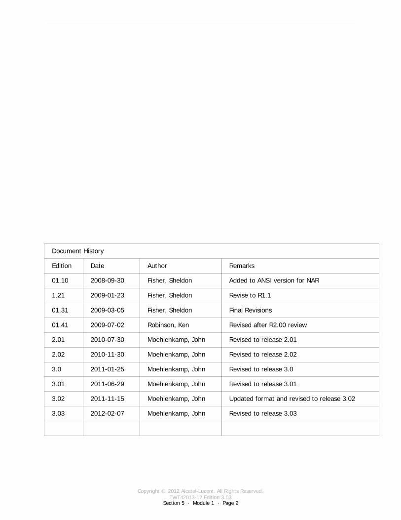
Copyright © 2012 Alcatel-Lucent. All Rights Reserved.TWT42013-12 Edition 3.03
Section 5 · Module 1 · Page 2
9500 MPR (Microwave Packet Radio) · Operations & Maintenance R3.03 (ANSI)Course · Summary5 · 1 · 2
COPYRIGHT © ALCATEL-LUCENT 2012. ALL RIGHTS RESERVED.
Blank page
This page is left blank intentionally
Document History
Edition Date Author Remarks
01.10 2008-09-30 Fisher, Sheldon Added to ANSI version for NAR
1.21 2009-01-23 Fisher, Sheldon Revise to R1.1
01.31 2009-03-05 Fisher, Sheldon Final Revisions
01.41 2009-07-02 Robinson, Ken Revised after R2.00 review
2.01 2010-07-30 Moehlenkamp, John Revised to release 2.01
2.02 2010-11-30 Moehlenkamp, John Revised to release 2.02
3.0 2011-01-25 Moehlenkamp, John Revised to release 3.0
3.01 2011-06-29 Moehlenkamp, John Revised to release 3.01
3.02 2011-11-15 Moehlenkamp, John Updated format and revised to release 3.02
3.03 2012-02-07 Moehlenkamp, John Revised to release 3.03
Copyright © 2012 Alcatel-Lucent. All Rights Reserved.TWT42013-12 Edition 3.03
Section 5 · Module 1 · Page 3
9500 MPR (Microwave Packet Radio) · Operations & Maintenance R3.03 (ANSI)Course · Summary5 · 1 · 3
COPYRIGHT © ALCATEL-LUCENT 2012. ALL RIGHTS RESERVED.
Course objectives
Upon completion of this course, you should be able to:
Describe the basic concepts of the 9500 MPR-ARespond to and manage alarm conditionsMonitor system and application statusMaintain 9500 MPR-A hardware and software

Copyright © 2012 Alcatel-Lucent. All Rights Reserved.TWT42013-12 Edition 3.03
Section 5 · Module 1 · Page 4
9500 MPR (Microwave Packet Radio) · Operations & Maintenance R3.03 (ANSI)Course · Summary5 · 1 · 4
COPYRIGHT © ALCATEL-LUCENT 2012. ALL RIGHTS RESERVED.
Course objectives [cont.]
This page is left blank intentionally

Copyright © 2012 Alcatel-Lucent. All Rights Reserved.TWT42013-12 Edition 3.03
Section 5 · Module 1 · Page 5
9500 MPR (Microwave Packet Radio) · Operations & Maintenance R3.03 (ANSI)Course · Summary5 · 1 · 5
COPYRIGHT © ALCATEL-LUCENT 2012. ALL RIGHTS RESERVED.
Course outline
We have covered the following topics in this course:
Section 1. Course OverviewModule 1. Course Overview
Section 2. ProductModule 1. Product Overview
Section 3. Product ArchitectureModule 1. MSSModule 2. MPT-HLModule 3. Outdoor Units
Section 4. OperationModule 1. GUIModule 2. Cross-ConnectionsModule 3. Diagnosis and Performance MonitoringModule 4. Alarm Monitor/RSL HistoryModule 5. Remove Cross-ConnectionsModule 6. Browser
Section 5. CourseModule 1. Summary

Copyright © 2012 Alcatel-Lucent. All Rights Reserved.TWT42013-12 Edition 3.03
Section 5 · Module 1 · Page 6
9500 MPR (Microwave Packet Radio) · Operations & Maintenance R3.03 (ANSI)Course · Summary5 · 1 · 6
COPYRIGHT © ALCATEL-LUCENT 2012. ALL RIGHTS RESERVED.
End of moduleSummary

Copyright © 2012 Alcatel-Lucent. All Rights Reserved.TWT42013-13 Edition 3.03
Section 6 · Module 1 · Page 1
Do not delete this graphic elements in here:
All Rights Reserved © Alcatel-Lucent @@YEAR
Module 1Acronyms
TWT42013-13 Edition 3.03
Section 6Terms
9500 MPR (Microwave Packet Radio)Operations & Maintenance R3.03 (ANSI)
TWT42013 Edition 1.1
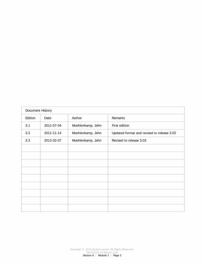
Copyright © 2012 Alcatel-Lucent. All Rights Reserved.TWT42013-13 Edition 3.03
Section 6 · Module 1 · Page 2
9500 MPR (Microwave Packet Radio) · Operations & Maintenance R3.03 (ANSI)Terms · Acronyms6 · 1 · 2
COPYRIGHT © ALCATEL-LUCENT 2012. ALL RIGHTS RESERVED.
Blank page
This page is left blank intentionally
Document History
Edition Date Author Remarks
3.1 2011-07-04 Moehlenkamp, John First edition
3.2 2011-11-14 Moehlenkamp, John Updated format and revised to release 3.02
3.3 2012-02-07 Moehlenkamp, John Revised to release 3.03
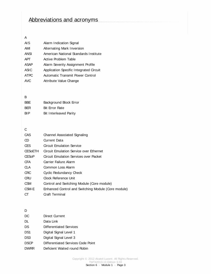
Copyright © 2012 Alcatel-Lucent. All Rights Reserved.TWT42013-13 Edition 3.03
Section 6 · Module 1 · Page 3
9500 MPR (Microwave Packet Radio) · Operations & Maintenance R3.03 (ANSI)Terms · Acronyms6 · 1 · 3
COPYRIGHT © ALCATEL-LUCENT 2012. ALL RIGHTS RESERVED.
Abbreviations and acronyms
Switch to notes view!A
AIS Alarm Indication Signal
AMI Alternating Mark Inversion
ANSI American National Standards Institute
APT Active Problem Table
ASAP Alarm Severity Assignment Profile
ASIC Application Specific Integrated Circuit
ATPC Automatic Transmit Power Control
AVC Attribute Value Change
B
BBE Background Block Error
BER Bit Error Rate
BIP Bit Interleaved Parity
C
CAS Channel Associated Signaling
CD Current Data
CES Circuit Emulation Service
CESoETH Circuit Emulation Service over Ethernet
CESoP Circuit Emulation Services over Packet
CFA Carrier Failure Alarm
CLA Common Loss Alarm
CRC Cyclic Redundancy Check
CRU Clock Reference Unit
CSM Control and Switching Module (Core module)
CSM-E Enhanced Control and Switching Module (Core module)
CT Craft Terminal
D
DC Direct Current
DL Data Link
DS Differentiated Services
DS1 Digital Signal Level 1
DS3 Digital Signal Level 3
DSCP Differentiated Services Code Point
DWRR Deficient Waited round Robin
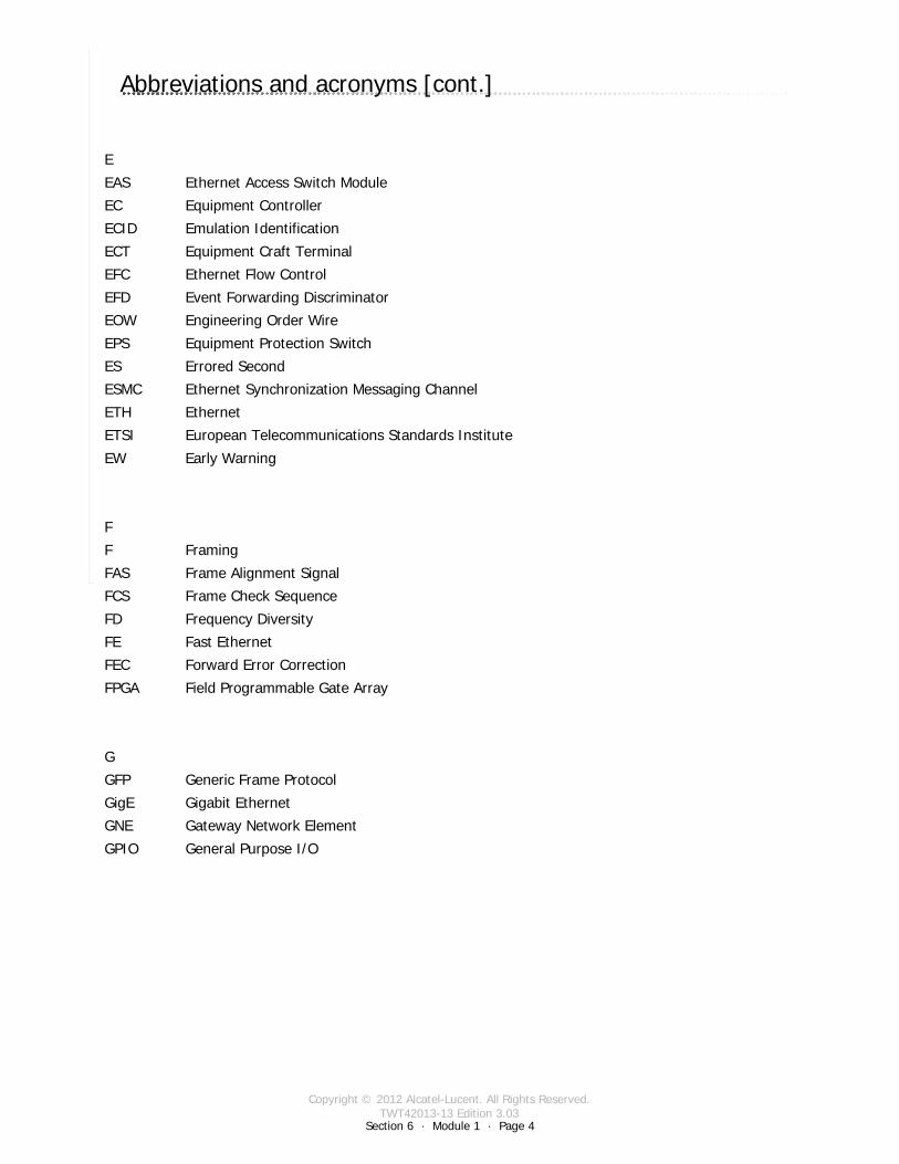
Copyright © 2012 Alcatel-Lucent. All Rights Reserved.TWT42013-13 Edition 3.03
Section 6 · Module 1 · Page 4
9500 MPR (Microwave Packet Radio) · Operations & Maintenance R3.03 (ANSI)Terms · Acronyms6 · 1 · 4
COPYRIGHT © ALCATEL-LUCENT 2012. ALL RIGHTS RESERVED.
Abbreviations and acronyms [cont.]
Switch to notes view!E
EAS Ethernet Access Switch Module
EC Equipment Controller
ECID Emulation Identification
ECT Equipment Craft Terminal
EFC Ethernet Flow Control
EFD Event Forwarding Discriminator
EOW Engineering Order Wire
EPS Equipment Protection Switch
ES Errored Second
ESMC Ethernet Synchronization Messaging Channel
ETH Ethernet
ETSI European Telecommunications Standards Institute
EW Early Warning
F
F Framing
FAS Frame Alignment Signal
FCS Frame Check Sequence
FD Frequency Diversity
FE Fast Ethernet
FEC Forward Error Correction
FPGA Field Programmable Gate Array
G
GFP Generic Frame Protocol
GigE Gigabit Ethernet
GNE Gateway Network Element
GPIO General Purpose I/O

Copyright © 2012 Alcatel-Lucent. All Rights Reserved.TWT42013-13 Edition 3.03
Section 6 · Module 1 · Page 5
9500 MPR (Microwave Packet Radio) · Operations & Maintenance R3.03 (ANSI)Terms · Acronyms6 · 1 · 5
COPYRIGHT © ALCATEL-LUCENT 2012. ALL RIGHTS RESERVED.
Abbreviations and acronyms [cont.]
Switch to notes view!H
HBER High Bit Error Ratio
HD History Data
HDB3 High Density order 3 Bipolar encoding
HET Hetero frequency
HQP High Queue Preempt
HS Hitless Switch
HSB Hot Standby
HSDPA High Speed Data Packet Access
HSSD Hot-Standby Space Diversity
HW Hardware
I
IDU Indoor Unit
ILM Infomodel Level Management
IM Information Model
IP Internet Protocol
ISAM Indexed Sequential Access Method
ISPB Intra Shelf Parallel Switching
IWF Interworking Function
J
JA Jitter Attenuator
JTAG Joint Test Action Group
JUSM Java User-based Security Model
K
L
LAN Local Area Network
LAPD Link Access Procedure on D-channel
LBER Low Bit Error Ration
LIM Link Identifier Mismatch
LIU Line Interface Unit
LOF Loss Of Frame
LOS Loss Of Signal
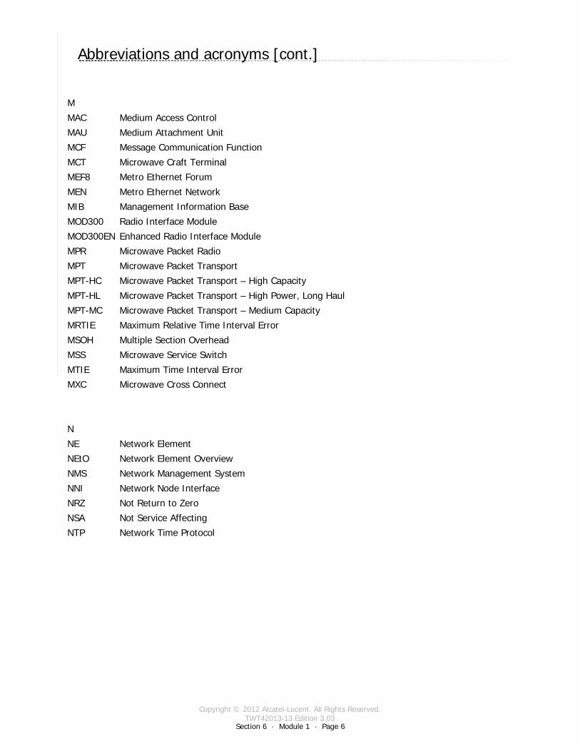
Copyright © 2012 Alcatel-Lucent. All Rights Reserved.TWT42013-13 Edition 3.03
Section 6 · Module 1 · Page 6
9500 MPR (Microwave Packet Radio) · Operations & Maintenance R3.03 (ANSI)Terms · Acronyms6 · 1 · 6
COPYRIGHT © ALCATEL-LUCENT 2012. ALL RIGHTS RESERVED.
Abbreviations and acronyms [cont.]
Switch to notes view!M
MAC Medium Access Control
MAU Medium Attachment Unit
MCF Message Communication Function
MCT Microwave Craft Terminal
MEF8 Metro Ethernet Forum
MEN Metro Ethernet Network
MIB Management Information Base
MOD300 Radio Interface Module
MOD300EN Enhanced Radio Interface Module
MPR Microwave Packet Radio
MPT Microwave Packet Transport
MPT-HC Microwave Packet Transport – High Capacity
MPT-HL Microwave Packet Transport – High Power, Long Haul
MPT-MC Microwave Packet Transport – Medium Capacity
MRTIE Maximum Relative Time Interval Error
MSOH Multiple Section Overhead
MSS Microwave Service Switch
MTIE Maximum Time Interval Error
MXC Microwave Cross Connect
N
NE Network Element
NEtO Network Element Overview
NMS Network Management System
NNI Network Node Interface
NRZ Not Return to Zero
NSA Not Service Affecting
NTP Network Time Protocol
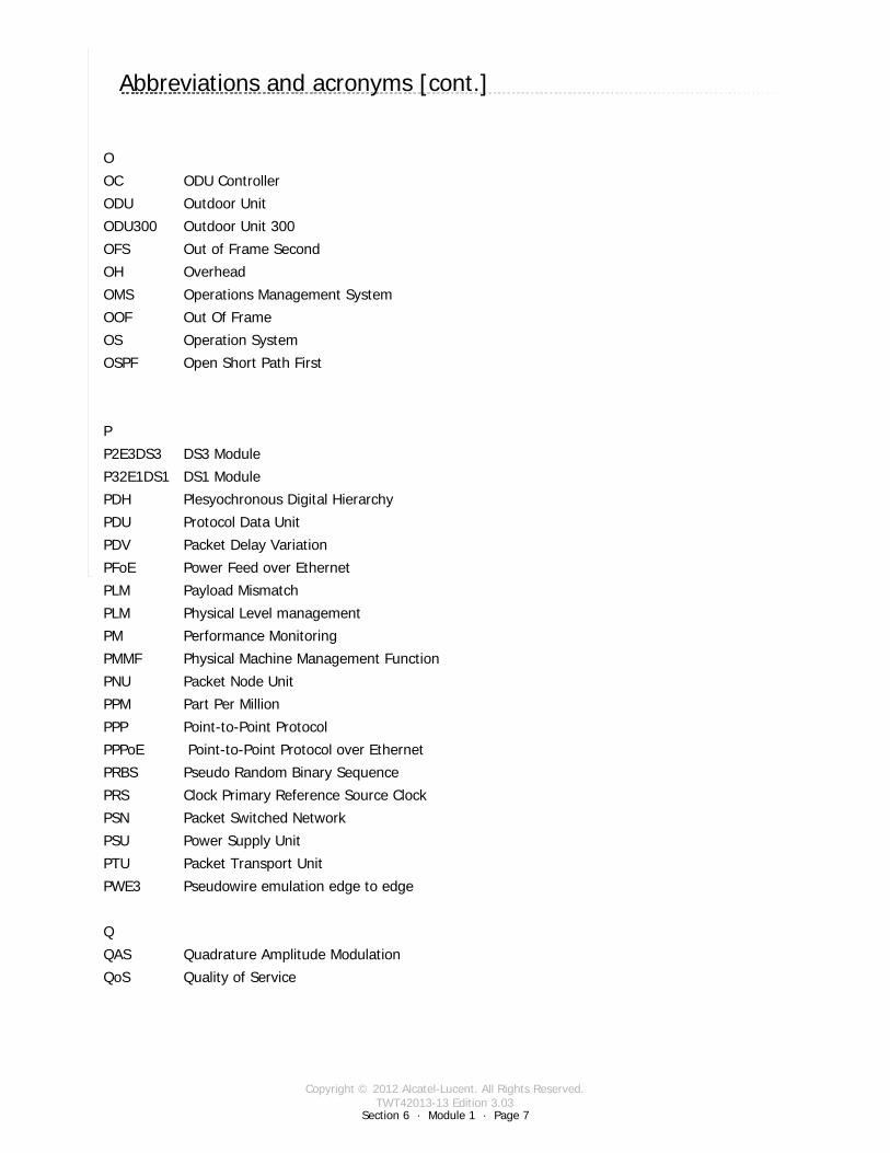
Copyright © 2012 Alcatel-Lucent. All Rights Reserved.TWT42013-13 Edition 3.03
Section 6 · Module 1 · Page 7
9500 MPR (Microwave Packet Radio) · Operations & Maintenance R3.03 (ANSI)Terms · Acronyms6 · 1 · 7
COPYRIGHT © ALCATEL-LUCENT 2012. ALL RIGHTS RESERVED.
Abbreviations and acronyms [cont.]
Switch to notes view!O
OC ODU Controller
ODU Outdoor Unit
ODU300 Outdoor Unit 300
OFS Out of Frame Second
OH Overhead
OMS Operations Management System
OOF Out Of Frame
OS Operation System
OSPF Open Short Path First
P
P2E3DS3 DS3 Module
P32E1DS1 DS1 Module
PDH Plesyochronous Digital Hierarchy
PDU Protocol Data Unit
PDV Packet Delay Variation
PFoE Power Feed over Ethernet
PLM Payload Mismatch
PLM Physical Level management
PM Performance Monitoring
PMMF Physical Machine Management Function
PNU Packet Node Unit
PPM Part Per Million
PPP Point-to-Point Protocol
PPPoE Point-to-Point Protocol over Ethernet
PRBS Pseudo Random Binary Sequence
PRS Clock Primary Reference Source Clock
PSN Packet Switched Network
PSU Power Supply Unit
PTU Packet Transport Unit
PWE3 Pseudowire emulation edge to edge
Q
QAS Quadrature Amplitude Modulation
QoS Quality of Service
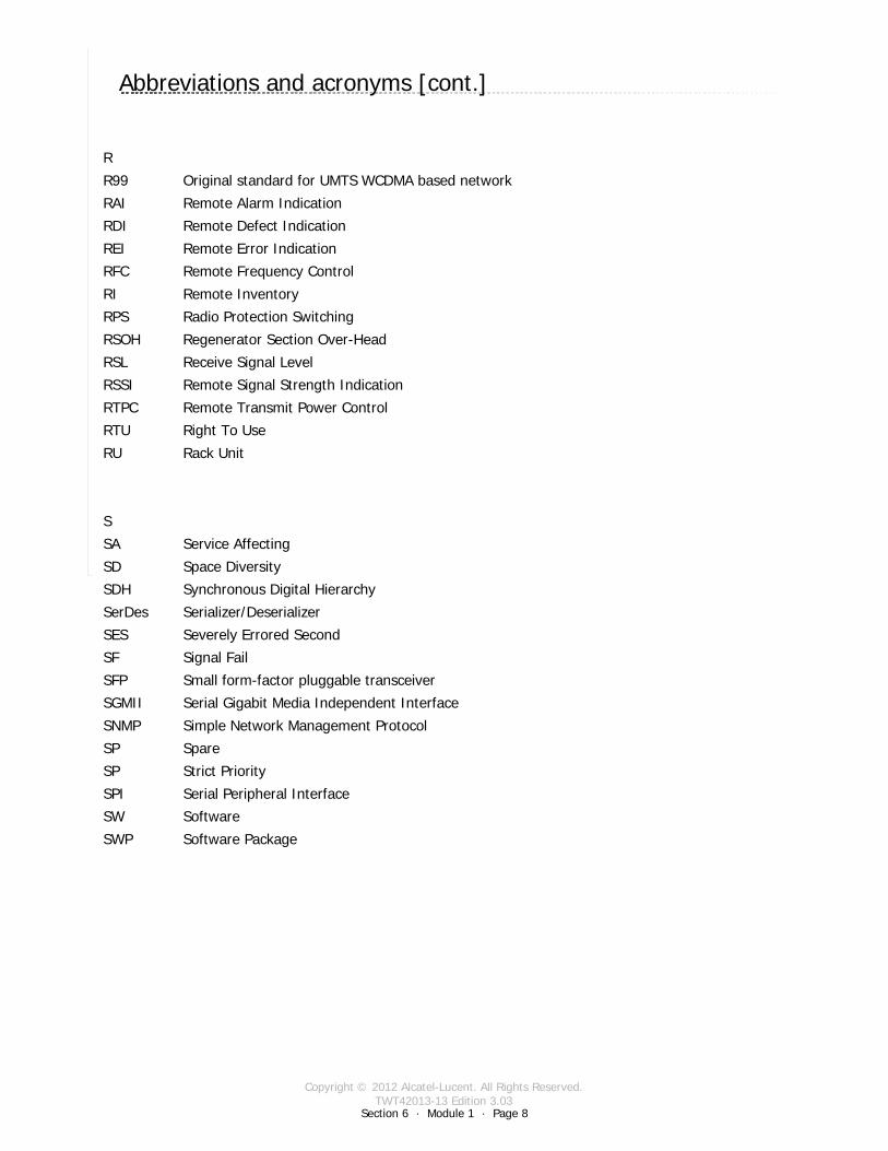
Copyright © 2012 Alcatel-Lucent. All Rights Reserved.TWT42013-13 Edition 3.03
Section 6 · Module 1 · Page 8
9500 MPR (Microwave Packet Radio) · Operations & Maintenance R3.03 (ANSI)Terms · Acronyms6 · 1 · 8
COPYRIGHT © ALCATEL-LUCENT 2012. ALL RIGHTS RESERVED.
Abbreviations and acronyms [cont.]
Switch to notes view!R
R99 Original standard for UMTS WCDMA based network
RAI Remote Alarm Indication
RDI Remote Defect Indication
REI Remote Error Indication
RFC Remote Frequency Control
RI Remote Inventory
RPS Radio Protection Switching
RSOH Regenerator Section Over-Head
RSL Receive Signal Level
RSSI Remote Signal Strength Indication
RTPC Remote Transmit Power Control
RTU Right To Use
RU Rack Unit
S
SA Service Affecting
SD Space Diversity
SDH Synchronous Digital Hierarchy
SerDes Serializer/Deserializer
SES Severely Errored Second
SF Signal Fail
SFP Small form-factor pluggable transceiver
SGMII Serial Gigabit Media Independent Interface
SNMP Simple Network Management Protocol
SP Spare
SP Strict Priority
SPI Serial Peripheral Interface
SW Software
SWP Software Package
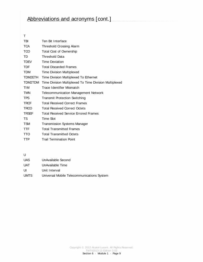
Copyright © 2012 Alcatel-Lucent. All Rights Reserved.TWT42013-13 Edition 3.03
Section 6 · Module 1 · Page 9
9500 MPR (Microwave Packet Radio) · Operations & Maintenance R3.03 (ANSI)Terms · Acronyms6 · 1 · 9
COPYRIGHT © ALCATEL-LUCENT 2012. ALL RIGHTS RESERVED.
Abbreviations and acronyms [cont.]
Switch to notes view!T
TBI Ten Bit Interface
TCA Threshold Crossing Alarm
TCO Total Cost of Ownership
TD Threshold Data
TDEV Time Deviation
TDF Total Discarded Frames
TDM Time Division Multiplexed
TDM2ETH Time Division Multiplexed To Ethernet
TDM2TDM Time Division Multiplexed To Time Division Multiplexed
TIM Trace Identifier Mismatch
TMN Telecommunication Management Network
TPS Transmit Protection Switching
TRCF Total Received Correct Frames
TRCO Total Received Correct Octets
TRSEF Total Received Service Errored Frames
TS Time Slot
TSM Transmission Systems Manager
TTF Total Transmitted Frames
TTO Total Transmitted Octets
TTP Trail Termination Point
U
UAS UnAvailable Second
UAT UnAvailable Time
UI Unit Interval
UMTS Universal Mobile Telecommunications System
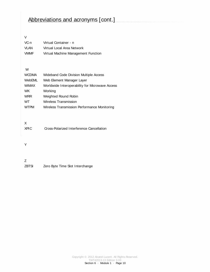
Copyright © 2012 Alcatel-Lucent. All Rights Reserved.TWT42013-13 Edition 3.03
Section 6 · Module 1 · Page 10
9500 MPR (Microwave Packet Radio) · Operations & Maintenance R3.03 (ANSI)Terms · Acronyms6 · 1 · 10
COPYRIGHT © ALCATEL-LUCENT 2012. ALL RIGHTS RESERVED.
Abbreviations and acronyms [cont.]
Switch to notes view!V
VC-n Virtual Container - n
VLAN Virtual Local Area Network
VMMF Virtual Machine Management Function
W
WCDMA Wideband Code Division Multiple Access
WebEML Web Element Manager Layer
WiMAX Worldwide Interoperability for Microwave Access
WK Working
WRR Weighted Round Robin
WT Wireless Transmission
WTPM Wireless Transmission Performance Monitoring
X
XPIC Cross-Polarized Interference Cancellation
Y
Z
ZBTSI Zero Byte Time Slot Interchange

Copyright © 2012 Alcatel-Lucent. All Rights Reserved.TWT42013-13 Edition 3.03
9500 MPR (Microwave Packet Radio) · Operations & Maintenance R3.03 (ANSI)Terms · Acronyms6 · 1 · 11
COPYRIGHT © ALCATEL-LUCENT 2012. ALL RIGHTS RESERVED.
Blank Page
Switch to notes view!
This page intentionally left blank
Section 6 · Module 1 · Page 11
Copyright © 2012 Alcatel-Lucent. All Rights Reserved.TWT42013-13 Edition 3.03
Section 6 · Module 1 · Page 12
9500 MPR (Microwave Packet Radio) · Operations & Maintenance R3.03 (ANSI)Terms · Acronyms6 · 1 · 12
COPYRIGHT © ALCATEL-LUCENT 2012. ALL RIGHTS RESERVED.
End of moduleAcronyms

Copyright © 2012 Alcatel-Lucent. All Rights Reserved.TWT42013-14 Edition 3.03
Section 7 · Module 1 · Page 1
Do not delete this graphic elements in here:
All Rights Reserved © Alcatel-Lucent @@YEAR
Module 1Labs
TWT42013-14 Edition 3.03
Section 7Exercises
9500 MPR (Microwave Packet Radio)Operations & Maintenance R3.03 (ANSI)
TWT42013 Edition 1.1
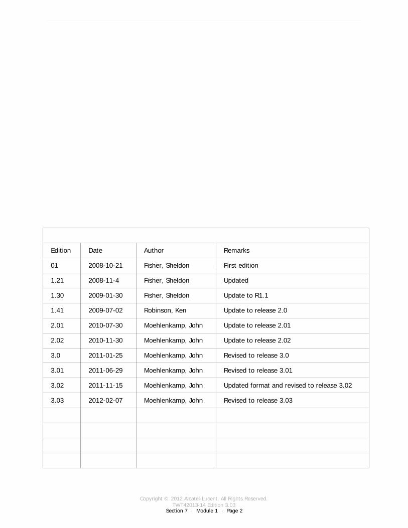
Copyright © 2012 Alcatel-Lucent. All Rights Reserved.TWT42013-14 Edition 3.03
Section 7 · Module 1 · Page 2
9500 MPR (Microwave Packet Radio) · Operations & Maintenance R3.03 (ANSI)Exercises · Labs7 · 1 · 2
COPYRIGHT © ALCATEL-LUCENT 2012. ALL RIGHTS RESERVED.
Blank page
This page is left blank intentionally
Revised to release 3.03Moehlenkamp, John2012-02-073.03
Edition Date Author Remarks
01 2008-10-21 Fisher, Sheldon First edition
1.21 2008-11-4 Fisher, Sheldon Updated
1.30 2009-01-30 Fisher, Sheldon Update to R1.1
1.41 2009-07-02 Robinson, Ken Update to release 2.0
2.01 2010-07-30 Moehlenkamp, John Update to release 2.01
2.02 2010-11-30 Moehlenkamp, John Update to release 2.02
3.0 2011-01-25 Moehlenkamp, John Revised to release 3.0
3.01 2011-06-29 Moehlenkamp, John Revised to release 3.01
3.02 2011-11-15 Moehlenkamp, John Updated format and revised to release 3.02
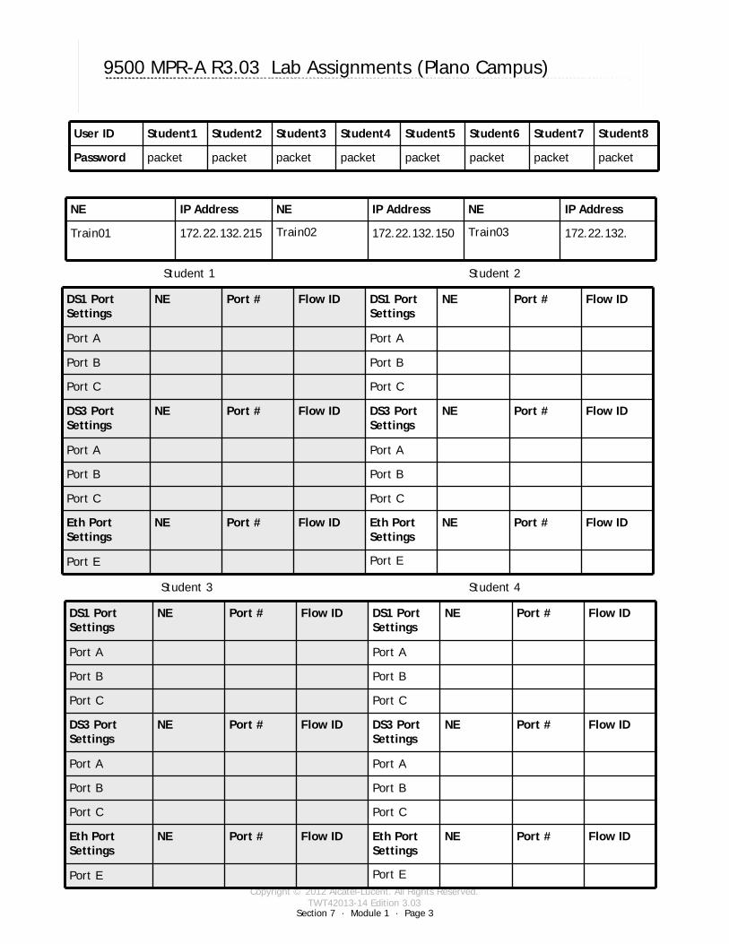
Copyright © 2012 Alcatel-Lucent. All Rights Reserved.TWT42013-14 Edition 3.03
Section 7 · Module 1 · Page 3
9500 MPR (Microwave Packet Radio) · Operations & Maintenance R3.03 (ANSI)Exercises · Labs7 · 1 · 3
COPYRIGHT © ALCATEL-LUCENT 2012. ALL RIGHTS RESERVED.
9500 MPR-A R3.03 Lab Assignments (Plano Campus)
User ID Student1 Student2 Student3 Student4 Student5 Student6 Student7 Student8
Password packet packet packet packet packet packet packet packet
NE IP Address NE IP Address NE IP Address
Train01 172.22.132.215 Train02 172.22.132.150 Train03 172.22.132.
DS1 Port Settings
NE Port # Flow ID DS1 Port Settings
NE Port # Flow ID
Port A Port A
Port B Port B
Port C Port C
DS3 Port Settings
NE Port # Flow ID DS3 Port Settings
NE Port # Flow ID
Port A Port A
Port B Port B
Port C Port C
Eth Port Settings
NE Port # Flow ID Eth Port Settings
NE Port # Flow ID
Port E Port E
Student 1 Student 2
Student 3 Student 4
DS1 Port Settings
NE Port # Flow ID DS1 Port Settings
NE Port # Flow ID
Port A Port A
Port B Port B
Port C Port C
DS3 Port Settings
NE Port # Flow ID DS3 Port Settings
NE Port # Flow ID
Port A Port A
Port B Port B
Port C Port C
Eth Port Settings
NE Port # Flow ID Eth Port Settings
NE Port # Flow ID
Port E Port E

Copyright © 2012 Alcatel-Lucent. All Rights Reserved.TWT42013-14 Edition 3.03
Section 7 · Module 1 · Page 4
9500 MPR (Microwave Packet Radio) · Operations & Maintenance R3.03 (ANSI)Exercises · Labs7 · 1 · 4
COPYRIGHT © ALCATEL-LUCENT 2012. ALL RIGHTS RESERVED.
9500 MPR-A R3.03 Lab Assignments (Plano Campus) [cont.]
Student 5 Student 6
Student 7 Student 8
DS1 Port Settings
NE Port # Flow ID DS1 Port Settings
NE Port # Flow ID
Port A Port A
Port B Port B
Port C Port C
DS3 Port Settings
NE Port # Flow ID DS3 Port Settings
NE Port # Flow ID
Port A Port A
Port B Port B
Port C Port C
Eth Port Settings
NE Port # Flow ID Eth Port Settings
NE Port # Flow ID
Port E Port E
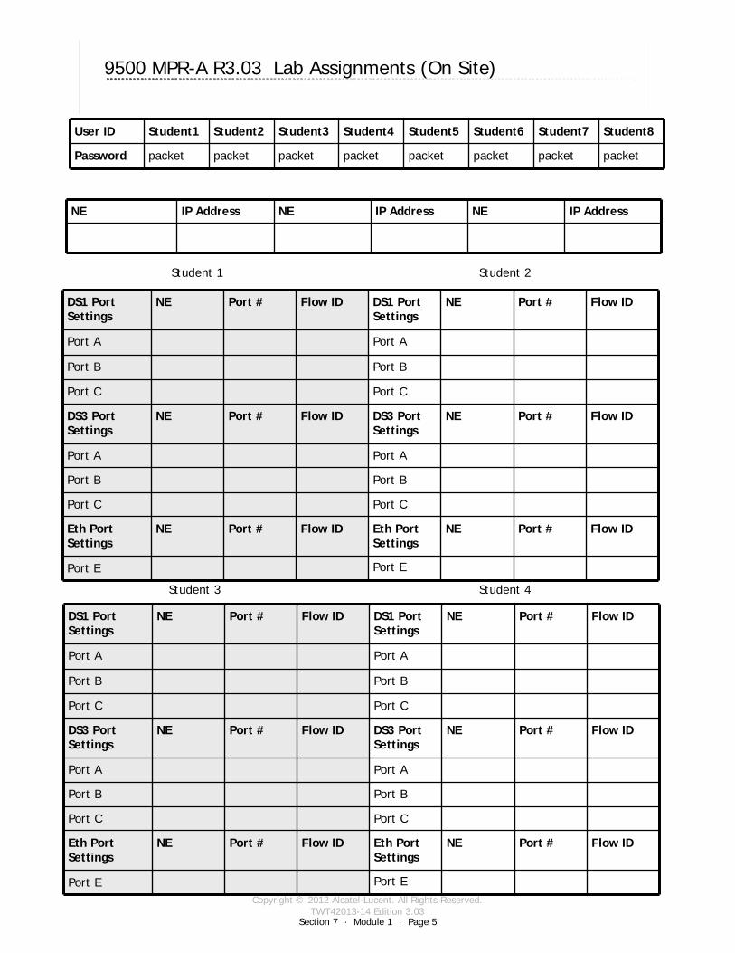
Copyright © 2012 Alcatel-Lucent. All Rights Reserved.TWT42013-14 Edition 3.03
Section 7 · Module 1 · Page 5
9500 MPR (Microwave Packet Radio) · Operations & Maintenance R3.03 (ANSI)Exercises · Labs7 · 1 · 5
COPYRIGHT © ALCATEL-LUCENT 2012. ALL RIGHTS RESERVED.
9500 MPR-A R3.03 Lab Assignments (On Site)
User ID Student1 Student2 Student3 Student4 Student5 Student6 Student7 Student8
Password packet packet packet packet packet packet packet packet
NE IP Address NE IP Address NE IP Address
DS1 Port Settings
NE Port # Flow ID DS1 Port Settings
NE Port # Flow ID
Port A Port A
Port B Port B
Port C Port C
DS3 Port Settings
NE Port # Flow ID DS3 Port Settings
NE Port # Flow ID
Port A Port A
Port B Port B
Port C Port C
Eth Port Settings
NE Port # Flow ID Eth Port Settings
NE Port # Flow ID
Port E Port E
Student 1 Student 2
Student 3 Student 4
DS1 Port Settings
NE Port # Flow ID DS1 Port Settings
NE Port # Flow ID
Port A Port A
Port B Port B
Port C Port C
DS3 Port Settings
NE Port # Flow ID DS3 Port Settings
NE Port # Flow ID
Port A Port A
Port B Port B
Port C Port C
Eth Port Settings
NE Port # Flow ID Eth Port Settings
NE Port # Flow ID
Port E Port E

Copyright © 2012 Alcatel-Lucent. All Rights Reserved.TWT42013-14 Edition 3.03
Section 7 · Module 1 · Page 6
9500 MPR (Microwave Packet Radio) · Operations & Maintenance R3.03 (ANSI)Exercises · Labs7 · 1 · 6
COPYRIGHT © ALCATEL-LUCENT 2012. ALL RIGHTS RESERVED.
9500 MPR-A R3.03 Lab Assignments (On Site) [cont.]
Student 5 Student 6
Student 7 Student 8
DS1 Port Settings
NE Port # Flow ID DS1 Port Settings
NE Port # Flow ID
Port A Port A
Port B Port B
Port C Port C
DS3 Port Settings
NE Port # Flow ID DS3 Port Settings
NE Port # Flow ID
Port A Port A
Port B Port B
Port C Port C
Eth Port Settings
NE Port # Flow ID Eth Port Settings
NE Port # Flow ID
Port E Port E
DS1 Port Settings
NE Port # Flow ID DS1 Port Settings
NE Port # Flow ID
Port A Port A
Port B Port B
Port C Port C
DS3 Port Settings
NE Port # Flow ID DS3 Port Settings
NE Port # Flow ID
Port A Port A
Port B Port B
Port C Port C
Eth Port Settings
NE Port # Flow ID Eth Port Settings
NE Port # Flow ID
Port E Port E
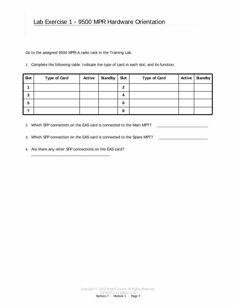
Copyright © 2012 Alcatel-Lucent. All Rights Reserved.TWT42013-14 Edition 3.03
Section 7 · Module 1 · Page 7
9500 MPR (Microwave Packet Radio) · Operations & Maintenance R3.03 (ANSI)Exercises · Labs7 · 1 · 7
COPYRIGHT © ALCATEL-LUCENT 2012. ALL RIGHTS RESERVED.
Lab Exercise 1 - 9500 MPR Hardware Orientation
Go to the assigned 9500 MPR-A radio rack in the Training Lab.
1. Complete the following table. Indicate the type of card in each slot, and its function.
2. Which SFP connection on the EAS card is connected to the Main MPT? ________________________
3. Which SFP connection on the EAS card is connected to the Spare MPT? _______________________
4. Are there any other SFP connections on the EAS card? _____________________________________
Slot Type of Card Active Standby Slot Type of Card Active Standby
1 2
3 4
5 6
7 8

Copyright © 2012 Alcatel-Lucent. All Rights Reserved.TWT42013-14 Edition 3.03
Section 7 · Module 1 · Page 8
9500 MPR (Microwave Packet Radio) · Operations & Maintenance R3.03 (ANSI)Exercises · Labs7 · 1 · 8
COPYRIGHT © ALCATEL-LUCENT 2012. ALL RIGHTS RESERVED.
Lab Exercise 2 - Operator GUI - NEtO Overview
Reference: MSS HW Hardware Module
Preparation: Logon to Microsoft Windows on your class computer using your instructor-assigned User ID and Password.
1.Activate the NEtO application by clicking on the icon on the desktop.
2.Enter the assigned IP address for your group and click on ‘OK’.
3.Complete the following information:
Site Name:
Site Location:
4.Click on ‘Show’ to start supervision. If the supervision does not start, record the error message received.
5.When the Login dialog box opens, use the following to log on to the MSS:
Logon:
Password:
When the NE Main View opens, keep it open for the next exercise.
Alarm Color Number
Critical
Major
Minor
Warning
Indeterminate

Copyright © 2012 Alcatel-Lucent. All Rights Reserved.TWT42013-14 Edition 3.03
Section 7 · Module 1 · Page 9
9500 MPR (Microwave Packet Radio) · Operations & Maintenance R3.03 (ANSI)Exercises · Labs7 · 1 · 9
COPYRIGHT © ALCATEL-LUCENT 2012. ALL RIGHTS RESERVED.
Lab Exercise 3 - Operator GUI - NE Main View
Reference: MSS HW Hardware Module
Preparation1.You must be logged into Microsoft Windows on your class computer.
2. You must have the NEtO application running.
3. You must be logged onto the application and have the NE Main View open.
Compare the information in the Current Alarms table in Exercise #2 with the information in the Alarm Severity Panel in the Main View. (sample shown at top of table). Complete the information in the following table:
(sample Alarm Severity Panel)
CRI MAJ MIN WNG IND
Same Diff Same Diff Same Diff Same Diff Same Diff

Copyright © 2012 Alcatel-Lucent. All Rights Reserved.TWT42013-14 Edition 3.03
Section 7 · Module 1 · Page 10
9500 MPR (Microwave Packet Radio) · Operations & Maintenance R3.03 (ANSI)Exercises · Labs7 · 1 · 10
COPYRIGHT © ALCATEL-LUCENT 2012. ALL RIGHTS RESERVED.
Lab Exercise 3 - Operator GUI - NE Main View [cont.]
1. Total the number of alarms shown in the Alarm Severity Panel: _____________
2. Now total the number of alarms shown in the Domain Synthesis Panel:_______
3. Is there a difference? __________________
Click on the Synchronization Tab. What type of synchronization is being used?
________________________________________________________________________
4. Click on the Synchronization Source Tab.
5. Click on the Protection Tab. Complete the following table:
6. Return to the NE Main View for the next Exercise.
Protection Type
Slot Port CH Role Status Command Criteria

Copyright © 2012 Alcatel-Lucent. All Rights Reserved.TWT42013-14 Edition 3.03
Section 7 · Module 1 · Page 11
9500 MPR (Microwave Packet Radio) · Operations & Maintenance R3.03 (ANSI)Exercises · Labs7 · 1 · 11
COPYRIGHT © ALCATEL-LUCENT 2012. ALL RIGHTS RESERVED.
Lab Exercise 4 - NEtO Menus
Reference: MSS HW Hardware Module
Preparation1. You must be logged into Microsoft Windows on your class computer.
2. You must have the NEtO application running.
3. You must be logged onto the application and have the NE Main View open.
Click on the Views Menu. Compare clicking on each of the last four selections of the
Menu with clicking on the Tabs in the Equipment view.
Click on the Configuration Menu.
1. What is the Local Configuration IP Address. _____________________________________
2. Click on Current Configuration. Answer the following questions:
a. What is the TX frequency? _______________________________
b. What is the status of the TMN RF MANAGEMENT port? _________________________
c. What is the status of DHCP? ______________________________
d. What is the configuration of the CSM-E? _________________________
Click on the SW Download Menu. Click on the SW Status selection.
1. Committed software
a. Which Bank is Committed?_____________________________________________
b. What is the software Version? __________________________________________
2. Standby software
c. Which Bank is Standby? ______________________________________________
d. What is the software Version? __________________________________________

Copyright © 2012 Alcatel-Lucent. All Rights Reserved.TWT42013-14 Edition 3.03
Section 7 · Module 1 · Page 12
9500 MPR (Microwave Packet Radio) · Operations & Maintenance R3.03 (ANSI)Exercises · Labs7 · 1 · 12
COPYRIGHT © ALCATEL-LUCENT 2012. ALL RIGHTS RESERVED.
Lab Exercise 5 - MPT-HL and MOD300 Configuration
Determine MPT Provisioning
1.Select the MSS/MPT Dir#-Ch# in the Resource Tree area.
2.Determine if the selected name is highlighted in yellow. ___Yes __No
3.Determine if the selection is highlighted the MSS/MPT icon in blue. ___Yes __No
4.Double-click the blue MSS/MPT icon and the RF Settings screen should display.
5. List channel spacing
6. List modulation scheme
7. List the Rx RF Frequency
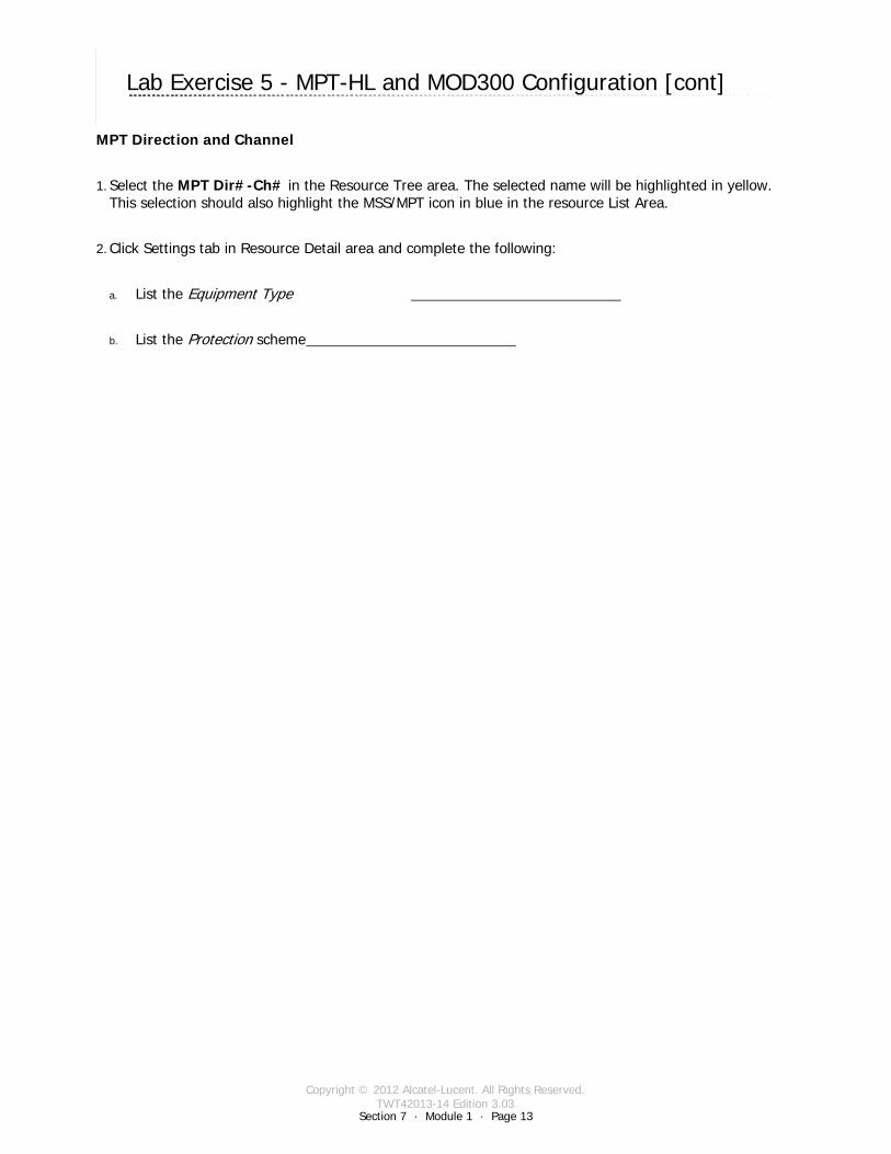
Copyright © 2012 Alcatel-Lucent. All Rights Reserved.TWT42013-14 Edition 3.03
Section 7 · Module 1 · Page 13
9500 MPR (Microwave Packet Radio) · Operations & Maintenance R3.03 (ANSI)Exercises · Labs7 · 1 · 13
COPYRIGHT © ALCATEL-LUCENT 2012. ALL RIGHTS RESERVED.
Lab Exercise 5 - MPT-HL and MOD300 Configuration [cont]
MPT Direction and Channel
1.Select the MPT Dir#-Ch# in the Resource Tree area. The selected name will be highlighted in yellow. This selection should also highlight the MSS/MPT icon in blue in the resource List Area.
2.Click Settings tab in Resource Detail area and complete the following:
a. List the Equipment Type
b. List the Protection scheme

Copyright © 2012 Alcatel-Lucent. All Rights Reserved.TWT42013-14 Edition 3.03
Section 7 · Module 1 · Page 14
9500 MPR (Microwave Packet Radio) · Operations & Maintenance R3.03 (ANSI)Exercises · Labs7 · 1 · 14
COPYRIGHT © ALCATEL-LUCENT 2012. ALL RIGHTS RESERVED.
Lab Exercise 6 - Configure DS1 Ports
1. You must be logged into Microsoft Windows on your class computer.
2. You must have the NEtO application running.
3. Configure the ports according to the following information:
4. Check for any new alarms that have occurred because you configured the ports.
List them below:
Return to the NE Main View for the next Exercise.
Signal Mode Service Profile Line Coding
Framed ESF TDM2TDM B8ZS
Event Time Probable Cause Friendly Name Severity

Copyright © 2012 Alcatel-Lucent. All Rights Reserved.TWT42013-14 Edition 3.03
Section 7 · Module 1 · Page 15
9500 MPR (Microwave Packet Radio) · Operations & Maintenance R3.03 (ANSI)Exercises · Labs7 · 1 · 15
COPYRIGHT © ALCATEL-LUCENT 2012. ALL RIGHTS RESERVED.
Lab Exercise 7 - DS1 Cross-Connections
1. You must be logged into Microsoft Windows on your class computer.
2. You must have the NEtO application running.
3. You must have the DS1, DS3, and Ethernet ports configured in Lab Exercises 6, 7. and 8.
4. Click on the cross-connections icon to open the cross-connections screen.
5. What are the colors of the connectors before you make the cross-connection?DS1 ________________ Radio _____________
6. Make the cross-connections as directed by the instructor.
7. What are the colors of the connectors after you made the cross-connection?
DS1 ________________ Radio _____________
8. What is the color of the cross-connection line?
________________________________________________________________________
9. List any new Alarms that have occurred as a result of making the cross-connections.
Close the cross-connections screen and return to the NE Main View for the next Exercise.
Event Time Probable Cause Friendly Name Severity

Copyright © 2012 Alcatel-Lucent. All Rights Reserved.TWT42013-14 Edition 3.03
Section 7 · Module 1 · Page 16
9500 MPR (Microwave Packet Radio) · Operations & Maintenance R3.03 (ANSI)Exercises · Labs7 · 1 · 16
COPYRIGHT © ALCATEL-LUCENT 2012. ALL RIGHTS RESERVED.
Lab Exercise 8 - Configure DS3 Ports
1. You must be logged into Microsoft Windows on your class computer.
2. You must have the NEtO application running.
Configure the ports according to the following information:
3. Check for any new alarms that have occurred because you configured the ports.
List them below:
Return to the NE Main View for the next Exercise.
Signal Mode Service Profile
Framed TDM2TDM
Event Time Probable Cause Friendly Name Severity

Copyright © 2012 Alcatel-Lucent. All Rights Reserved.TWT42013-14 Edition 3.03
Section 7 · Module 1 · Page 17
9500 MPR (Microwave Packet Radio) · Operations & Maintenance R3.03 (ANSI)Exercises · Labs7 · 1 · 17
COPYRIGHT © ALCATEL-LUCENT 2012. ALL RIGHTS RESERVED.
Lab Exercise 9 - DS3 Cross-Connections
1. You must be logged into Microsoft Windows on your class computer.
2. You must have the NEtO application running.
3. You must have the DS1, DS3, and Ethernet ports configured in Lab Exercises 6, 7. and 8.
4. Click on the cross-connections icon to open the cross-connections screen.
5. What are the colors of the connectors before you make the cross-connection?DS3 ________________ Radio _____________
6. Make the cross-connections as directed by the instructor.
7. What are the colors of the connectors after you made the cross-connection?
DS3 ________________ Radio _____________
8. What is the color of the cross-connection line?
________________________________________________________________________
List any new Alarms that have occurred as a result of making the cross-connections.
Close the cross-connections screen and return to the NE Main View for the next Exercise.
Event Time Probable Cause Friendly Name Severity
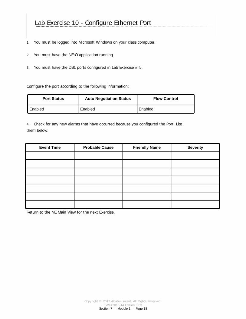
Copyright © 2012 Alcatel-Lucent. All Rights Reserved.TWT42013-14 Edition 3.03
Section 7 · Module 1 · Page 18
9500 MPR (Microwave Packet Radio) · Operations & Maintenance R3.03 (ANSI)Exercises · Labs7 · 1 · 18
COPYRIGHT © ALCATEL-LUCENT 2012. ALL RIGHTS RESERVED.
Lab Exercise 10 - Configure Ethernet Port
1. You must be logged into Microsoft Windows on your class computer.
2. You must have the NEtO application running.
3. You must have the DS1 ports configured in Lab Exercise # 5.
Configure the port according to the following information:
4. Check for any new alarms that have occurred because you configured the Port. List
them below:
Return to the NE Main View for the next Exercise.
Port Status Auto Negotiation Status Flow Control
Enabled Enabled Enabled
Event Time Probable Cause Friendly Name Severity

Copyright © 2012 Alcatel-Lucent. All Rights Reserved.TWT42013-14 Edition 3.03
Section 7 · Module 1 · Page 19
9500 MPR (Microwave Packet Radio) · Operations & Maintenance R3.03 (ANSI)Exercises · Labs7 · 1 · 19
COPYRIGHT © ALCATEL-LUCENT 2012. ALL RIGHTS RESERVED.
Lab Exercise 11 - Ethernet Cross-Connections
1. You must be logged into Microsoft Windows on your class computer.
2. You must have the NEtO application running.
3. You must have the DS1, DS3, and Ethernet ports configured in Lab Exercises 6, 7. and 8.
4. Click on the cross-connections icon to open the cross-connections screen.
5. What are the colors of the connectors before you make the cross-connection?
Ethernet ________________ Radio _____________
6. Make the cross-connection as follows:
7. What are the colors of the connectors after you made the cross-connection?
Ethernet ________________ Radio _____________
8. What is the color of the cross-connection line?
________________________________________________________________________
List any new Alarms that have occurred as a result of making the cross-connections.
Close the cross-connections screen and return to the NE Main View for the next Exercise.
Event Time Probable Cause Friendly Name Severity
Event Time Probable Cause Friendly Name Severity
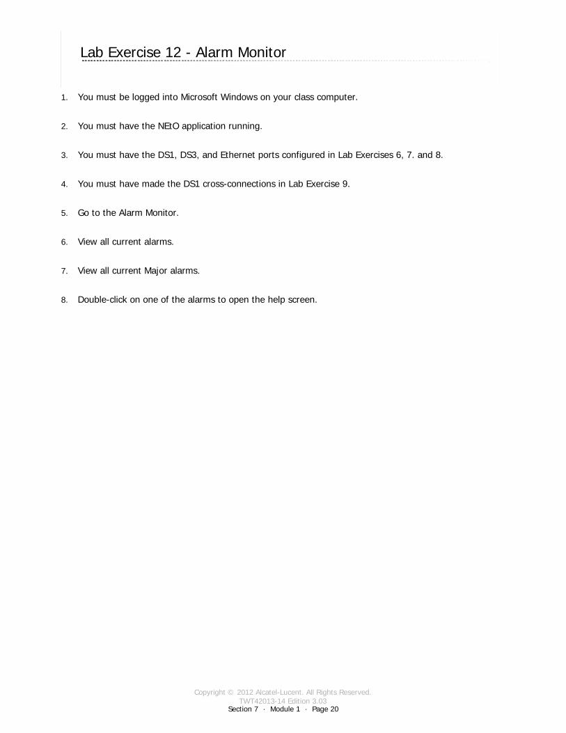
Copyright © 2012 Alcatel-Lucent. All Rights Reserved.TWT42013-14 Edition 3.03
Section 7 · Module 1 · Page 20
9500 MPR (Microwave Packet Radio) · Operations & Maintenance R3.03 (ANSI)Exercises · Labs7 · 1 · 20
COPYRIGHT © ALCATEL-LUCENT 2012. ALL RIGHTS RESERVED.
Lab Exercise 12 - Alarm Monitor
1. You must be logged into Microsoft Windows on your class computer.
2. You must have the NEtO application running.
3. You must have the DS1, DS3, and Ethernet ports configured in Lab Exercises 6, 7. and 8.
4. You must have made the DS1 cross-connections in Lab Exercise 9.
5. Go to the Alarm Monitor.
6. View all current alarms.
7. View all current Major alarms.
8. Double-click on one of the alarms to open the help screen.

Copyright © 2012 Alcatel-Lucent. All Rights Reserved.TWT42013-14 Edition 3.03
Section 7 · Module 1 · Page 21
9500 MPR (Microwave Packet Radio) · Operations & Maintenance R3.03 (ANSI)Exercises · Labs7 · 1 · 21
COPYRIGHT © ALCATEL-LUCENT 2012. ALL RIGHTS RESERVED.
Lab Exercise 13 - Remove DS1 Cross-Connections
1. You must be logged into Microsoft Windows on your class computer.
2. You must have the NEtO application running.
3. You must have the DS1, DS3, and Ethernet ports configured in Lab Exercises 6, 7. and 8.
4. You must have made the DS1 cross-connections in Lab Exercise 9.
5. Click on the cross-connections icon to open the cross-connections screen.
6. Remove the cross-connections as directed by the instructor.
7. What are the colors of the connectors before you make the cross-connection?
DS1 ________________ Radio _____________
8. What are the colors of the connectors after you made the cross-connection?
DS1 ________________ Radio _____________
9. Did the cross-connection line disappear? Yes ____________ No _____________
10. If the cross-connection line disappeared, explain why that happened:
____________________________________________________________________________________
11. If the cross-connection line did not disappear, explain why it is still there:
____________________________________________________________________________________
12. List any new Alarms that have occurred as a result of removing the cross-connections.
13. Disable the DS1 ports you configured in Lab Exercise # 5.
14. Close the cross-connections screen and return to the NE Main View for the next Exercise.
Severity Event Time Entity Probable Cause

Copyright © 2012 Alcatel-Lucent. All Rights Reserved.TWT42013-14 Edition 3.03
Section 7 · Module 1 · Page 22
9500 MPR (Microwave Packet Radio) · Operations & Maintenance R3.03 (ANSI)Exercises · Labs7 · 1 · 22
COPYRIGHT © ALCATEL-LUCENT 2012. ALL RIGHTS RESERVED.
Lab Exercise 14 - Remove DS3 Cross-Connections
1. You must be logged into Microsoft Windows on your class computer.
2. You must have the NEtO application running.
3. You must have the DS1, DS3, and Ethernet ports configured in Lab Exercises 6, 7. and 8.
4. You must have made the DS1 cross-connections in Lab Exercise 9.
Click on the cross-connections icon to open the cross-connections screen.
Remove the cross-connections as directed by the instructor.
What were the colors of the connectors before you made the cross-connection?
DS3 ________________ Radio _____________
What are the colors of the connectors after you made the cross-connection?
DS3 ________________ Radio _____________
Did the cross-connection line disappear? Yes ____________ No _____________
If the cross-connection line disappeared, explain why that happened:
________________________________________________________________________
________________________________________________________________________
If the cross-connection line did not disappear, explain why it is still there:
________________________________________________________________________
________________________________________________________________________
List any new Alarms that have occurred as a result of removing the cross-connections.
Disable the DS1 ports you configured in Lab Exercise # 5.
Close the cross-connections screen and return to the NE Main View for the next Exercise.
Severity Event Time Entity Probable Cause

Copyright © 2012 Alcatel-Lucent. All Rights Reserved.TWT42013-14 Edition 3.03
Section 7 · Module 1 · Page 23
9500 MPR (Microwave Packet Radio) · Operations & Maintenance R3.03 (ANSI)Exercises · Labs7 · 1 · 23
COPYRIGHT © ALCATEL-LUCENT 2012. ALL RIGHTS RESERVED.
Lab Exercise 15 - Remove Ethernet Cross-Connection
1. You must be logged into Microsoft Windows on your class computer.
2. You must have the NEtO application running.
3. You must have the DS1, DS3, and Ethernet ports configured in Lab Exercises 6, 7. and 8.
4. You must have made the Ethernet cross-connections in Lab Exercise 11.
Click on the cross-connections icon to open the cross-connections screen.
Remove the cross-connections as directed by the instructor.
What were the colors of the connectors before you made the cross-connection?
Ethernet ________________ Radio _____________
What are the colors of the connectors after you made the cross-connection?
Ethernet ________________ Radio _____________
Did the cross-connection line disappear? Yes ____________ No _____________
If the cross-connection line disappeared, explain why that happened:
________________________________________________________________________
________________________________________________________________________
If the cross-connection line did not disappear, explain why it is still there:
________________________________________________________________________
________________________________________________________________________
List any new Alarms that have occurred as a result of removing the cross-connections.
Disable the Ethernet port you configured in Lab Exercise # 7.
Close the cross-connections screen and return to the NE Main View for the next Exercise.
Severity Event Time Entity Probable Cause

Copyright © 2012 Alcatel-Lucent. All Rights Reserved.TWT42013-14 Edition 3.03
Section 7 · Module 1 · Page 24
9500 MPR (Microwave Packet Radio) · Operations & Maintenance R3.03 (ANSI)Exercises · Labs7 · 1 · 24
COPYRIGHT © ALCATEL-LUCENT 2012. ALL RIGHTS RESERVED.
Lab Exercise 16 - Remove Radio Cross-Connection
1. You must be logged into Microsoft Windows on your class computer.
2. You must have the NEtO application running.
3. You must have the DS1, DS3, and Ethernet ports configured in Lab Exercises 6, 7. and 8.
4. You must have made the Ethernet cross-connections in Lab Exercise 11.
Click on the cross-connections icon to open the cross-connections screen.
Remove the cross-connections as directed by the instructor.
What were the colors of the connectors before you made the cross-connection?
Ethernet ________________ Radio _____________
What are the colors of the connectors after you made the cross-connection?
Ethernet ________________ Radio _____________
Did the cross-connection line disappear? Yes ____________ No _____________
If the cross-connection line disappeared, explain why that happened:
________________________________________________________________________
________________________________________________________________________
If the cross-connection line did not disappear, explain why it is still there:
________________________________________________________________________
________________________________________________________________________
List any new Alarms that have occurred as a result of removing the cross-connections.
Disable the Ethernet port you configured in Lab Exercise # 7.
Close the cross-connections screen and return to the NE Main View for the next Exercise.
Severity Event Time Entity Probable Cause

Copyright © 2012 Alcatel-Lucent. All Rights Reserved.TWT42013-14 Edition 3.03
Section 7 · Module 1 · Page 25
9500 MPR (Microwave Packet Radio) · Operations & Maintenance R3.03 (ANSI)Exercises · Labs7 · 1 · 25
COPYRIGHT © ALCATEL-LUCENT 2012. ALL RIGHTS RESERVED.
Lab Exercise 17 - Browser Interface
1. Open a Web Browser. Type the IP Address of your assigned radio into the Address bar of the Web Browser.
2. When the Logon dialog box opens, use the following to log on:
Logon: ____________________________________________________________
Password: _________________________________________________________
3. How many Active Alarms are displayed?
4. Click on ‘Refresh’ . Recheck the Active Alarms.
5. Click on ‘Enable Automatic Refresh’. Recheck the Active Alarms in 5 minutes.
6. Click on > Date & Time Setting. Compare the Operating System Time with the GMT Time.
7. Click on > License Info. Examine the RMU Serial Number and License String.
8. Access the SW License information in the Browser View.
9. Logout from the Browser interface.
10. Return to the NE Main View for the next Exercise
Alarm Number
Critical
Major
Minor
Warning
Indeterminate

Copyright © 2012 Alcatel-Lucent. All Rights Reserved.TWT42013-14 Edition 3.03
Section 7 · Module 1 · Page 26
9500 MPR (Microwave Packet Radio) · Operations & Maintenance R3.03 (ANSI)Exercises · Labs7 · 1 · 26
COPYRIGHT © ALCATEL-LUCENT 2012. ALL RIGHTS RESERVED.
End of moduleLabs

All Rights Reserved © Alcatel-Lucent @@YEAR@@COURSENAME - Page 1
All Rights Reserved © Alcatel-Lucent @@YEAR
@@COURSENAME@@PRODUCT1
Last but one page
CongratulationsYou have finished the training
Your feedback is appreciated!Please feel free to Email your comments to:
Please include the training reference in your email (see cover page)
Thank you!

All Rights Reserved © Alcatel-Lucent @@YEAR@@COURSENAME - Page 2
All rights reserved © Alcatel-Lucent Passing on and copying of this document, use and communication of its contents not permitted without written authorization from Alcatel-Lucent