TWO YEARS IN BARCELONA WITH TAP WATER FROM ... - · PDF fileBarcelona and Dragados-Drace built...
16
TWO YEARS IN BARCELONA WITH TAP WATER FROM SWRO LLOBREGAT PLANT Authors: Miguel Angel SANZ, Carlos MIGUEL, Ramón ARBOS, María MUÑOZ, Josep MESA Presenter: María MUÑOZ Director of Production, Barcelona-Llobregat Desalination Plant, Degrémont SA, Spain Abstract Barcelona-Llobregat Desalination plant is actually the largest seawater desalination plant in Europe producing potable water from seawater of Mediterranean Sea. The plant is able to supply approximately the 20% of tap water of Barcelona Metropolitan area having a maximum capacity of 200 000 cubic meters per day. This Project was developed by ATLL (Aigües Ter-Llobregat) to face the lack of water resources and to improve the water quality in Barcelona’s south area. A Joint Venture of Degrémont, Aigues de Barcelona and Dragados-Drace built the plant during a severe drought period in an extremely tight delivery time of 24 months. A pilot plant was operating for two years to help in design and for getting experience with Mediterranean seawater. The plant was inaugurated on July 2009 and from this date the same JV is operating it. The facilities are located in El Prat, an industrial area between Barcelona Harbour and Llobregat mouth, just close to one of the waste water treatment plants of Barcelona, Baix Llobregat WWTP. A deep intake located 2 km offshore feed the plant avoiding the Llobregat river impact, especially for heavy rain period, and the harbour leaks. Sea water is pumped for more than three and a half km, crossing the river through an underground pipe. A very strong pre-treatment protect RO membranes: a set of 10 SeaDAF®, high speed flotators, is the first step followed by 20 Mediazur® gravity filters and 20 SeaClean® pressurised dual media filters. The polishing is guaranteed by 18 cartridge filters of 5 microns. The SDI 15 of pretreated seawater is always below 3.0 %/min, with an average of less than 2.5. 10 RO trains with an unitary production over 20 000 m3/day are fed by individuals HP pumps and the energy recovery is assured by a set of 23 PX220 per train. A partial second pass guarantees a Boron in treated water below 1.0 mg/l (two trains of 16 500 m3/day). Remineralisation is made with CO2 and up flow limestone filters with an innovative design. Potable water is pumped over 12 km to Fontsanta reservoirs to be blended with waters coming from one potable water plant with EDR treatment. In the distribution network is also blended with water coming from a second potable water plant, this one with a BW RO plant. Brine have an innovative treatment: is blended with treated water from the Waste Water Treatment Plant of Baix Llobregat in a ratio lower than 1:1 and discharged thought diffusers at 50 m depth over 3 km from intake. All effluents are treated before discharge and the plant has and sludge treatment with dewatering. Plant has also increase the “green label” adding a wind generator and photovoltaic panels in all building and reservoir roofs to minimise the electric internal consumption, saving more than 850 CO2 Ton/year. Barcelona-Llobregat SW RO plant won the Global Water Awards 2010 as Desalination Plant of the year. Wor World Congress/Perth Convention and Exhibition Centre (PCEC), Perth, Western Australia September 4-9, 2011 REF: IDAWC/PER11-073
Transcript of TWO YEARS IN BARCELONA WITH TAP WATER FROM ... - · PDF fileBarcelona and Dragados-Drace built...

TWO YEARS IN BARCELONA WITH TAP WATER FROM SWRO LLOBREGAT PLANT
Authors: Miguel Angel SANZ, Carlos MIGUEL, Ramón ARBOS, María MUÑOZ, Josep MESA
Presenter: María MUÑOZDirector of Production, Barcelona-Llobregat Desalination Plant, Degrémont SA, Spain
Abstract
Barcelona-Llobregat Desalination plant is actually the largest seawater desalination plant in Europe producing potable water from seawater of Mediterranean Sea. The plant is able to supply approximately the 20% of tap water of Barcelona Metropolitan area having a maximum capacity of 200 000 cubic meters per day.
This Project was developed by ATLL (Aigües Ter-Llobregat) to face the lack of water resources and to improve the water quality in Barcelona’s south area. A Joint Venture of Degrémont, Aigues de Barcelona and Dragados-Drace built the plant during a severe drought period in an extremely tight delivery time of 24 months. A pilot plant was operating for two years to help in design and for getting experience with Mediterranean seawater. The plant was inaugurated on July 2009 and from this date the same JV is operating it.
The facilities are located in El Prat, an industrial area between Barcelona Harbour and Llobregat mouth, just close to one of the waste water treatment plants of Barcelona, Baix Llobregat WWTP. A deep intake located 2 km offshore feed the plant avoiding the Llobregat river impact, especially for heavy rain period, and the harbour leaks. Sea water is pumped for more than three and a half km, crossing the river through an underground pipe. A very strong pre-treatment protect RO membranes: a set of 10 SeaDAF®, high speed flotators, is the first step followed by 20 Mediazur® gravity filters and 20 SeaClean® pressurised dual media filters. The polishing is guaranteed by 18 cartridge filters of 5 microns. The SDI15 of pretreated seawater is always below 3.0 %/min, with an average of less than 2.5.
10 RO trains with an unitary production over 20 000 m3/day are fed by individuals HP pumps and the energy recovery is assured by a set of 23 PX220 per train. A partial second pass guarantees a Boron in treated water below 1.0 mg/l (two trains of 16 500 m3/day). Remineralisation is made with CO2 and up flow limestone filters with an innovative design. Potable water is pumped over 12 km to Fontsanta reservoirs to be blended with waters coming from one potable water plant with EDR treatment. In the distribution network is also blended with water coming from a second potable water plant, this one with a BW RO plant.
Brine have an innovative treatment: is blended with treated water from the Waste Water Treatment Plant of Baix Llobregat in a ratio lower than 1:1 and discharged thought diffusers at 50 m depth over 3 km from intake. All effluents are treated before discharge and the plant has and sludge treatment with dewatering. Plant has also increase the “green label” adding a wind generator and photovoltaic panels in all building and reservoir roofs to minimise the electric internal consumption, saving more than 850 CO2 Ton/year.Barcelona-Llobregat SW RO plant won the Global Water Awards 2010 as Desalination Plant of the year.
Wor World Congress/Perth Convention and Exhibition Centre (PCEC), Perth, Western Australia September 4-9, 2011 REF: IDAWC/PER11-073

I INTRODUCTION
The Barcelona Metropolitan area has an historical lack of water resources to ensure a permanent guarantee of water supply. Additionally there is a quality problem due to the high hardness and salinity, coming from the salt mines in Suria and Cardona. Finally the lack of flexibility in the distribution network has not facilitated the optimization of resources management in Ter and Llobregat basins.
ATLL (Aigües Ter-Llobregat), public company of the Catalonian Government, has developed several actions focused on reducing the indicated deficiencies. The most significant action is the Llobregat Seawater Desalination Plant. Besides this one, they have added the extension and improvement of the Drinking Water Treatment Plant DWTP Abrera (including an EDR plant) and Sant Joan Despí (including and UF and BWRO plant), as well as the interconnection pipe between Fontsanta and Trinidad reservoirs. This allows to supply flows from the Ter river to the South of Barcelona or flow from the the DWTP Abrera and from the Llobregat Desalination Plant to the North of Barcelona, due to its reversible character. Due to this actions Barcelona have three plants including the three membrane technologies to desalt in few kilometres around the Llobregat River.
Fig. 1 – Situation of Works of Barcelona Plan
A Joint Venture of Degrémont, Aigues de Barcelona and Dragados-Drace built the plant during a severe drought period in an extremely tight delivery time of 24 months. The plant was inaugurated on July 2009 and from this date the same JV is operating it.
IDA World Congress – Perth Convention and Exhibition Centre (PCEC), Perth, Western Australia September 4-9, 2011REF: IDAWC/PER11-073
-2-

The Barcelona-Llobregat Plant is the main element to ensure the water supply in the area in case of severe drought. Because of this, being the largest in Europe, its quick commissioning, and for the innovations given to the Desalination World, it was awarded the prize of the Desalination Plant of the Year in the Global Water Awards 2010.
II PREVIOUS STUDIES AND PILOT PLANT
Three specific water studies were done, starting one year before the presentation of the proposals with the last after the client’s final decision. The water studies include pilot plant at Lab scale. One study per season evaluating the evolution of the seawater quality, and its influence in the design of the RO Plant (SDI, Temperature, TDS and so on) depending on the source of the seawater. The main objectives of the studies were to: improve knowledge of the raw water quality; validate the pre-treatment process; and determine of the optimum chemical regime and design parameters.
ATLL also performed several studies to decide the final intake:- One year of operation of a pilot sub-seabed drain.- Preliminary sea studies including on-line sample collection (turbidity, conductivity and temperasture)
Once ATLL selected the JV to build the plant a pilot plant was installed. This pilot had the same pretreatment elements as the real plant, but designed for 40m3/h. A lamellar clarifier (Pulsatube®) and a flotation with SeaDAF® were installed in parallel. Both units were followed by a double stage of Dual Media Filtration, cartridge filter and a reverse osmosis rack with a pressure vessel with 7 membranes of 8 inches, with a capacity to produce about 90 m3/day. A lime stone filter and CO2 dosing system were also incorporated to make remineralisation tests.
A specific open intake was built for this pilot at 1.075 m from the coast taken the seawater at 10 m. depth. This means worse quality conditions than in the definitive intake (25m depth at 2.200 m from the coast).
All tests proved that the planned treatment line was suitable. The SeaDAF® flotation was definitely selected as the best solution, with a non mechanic and piston flocculation, as the same as the definitive design of the rest of the components of its operating parameters. The performance of the RO membranes was also evaluated for a long time confirming the selected hybrid design.
In parallel to this pilot plant and taking profit from the sea water excess supplied by this intake, other Degrémont Research pilots have been installed in the same area, with different objectives, making easier the synergy between the different platforms to create an Research Platform for Seawater treatment. The pilot has been working until 2010.
III PLANT DESCRIPTION
The sea water intake is located at 2200 m from the coast, at about 30 m depth using a double polyethylene conduit of 1800 mm diameter, with 2 intake towers that allow to capture sea water at about 25 m in depth. This intake avoids that any influence of particles discharge from the Llobregat river, even with the worst storms. This double conception ensures the operation of the plant, at great flow and also with one of the intakes under maintenance.
IDA World Congress – Perth Convention and Exhibition Centre (PCEC), Perth, Western Australia September 4-9, 2011REF: IDAWC/PER11-073
-3-

The intake pipes were built in Norway and transported floating to Barcelona in stretches of 500 m length. In the port of Barcelona the concrete ballasts were installed and were transported to its location at the dug marine bottom.The solution of the sub-seabed drains was ruled out because of the space needed to install the drains interconnection and the pump station, as well as the doubts of clogging in the future.
Fig. 2- Transporting intake pipes from Oslo
Seawater pump station is located closed to the beach of Prat of Llobregat. After screening six pumps with frequency converters, to minimize electrical consumption, send the seawater to the plant through a pipe, crossing the river under his course.
After fine screening water go to the coagulation chambers and the piston flocculation areas of 10 SeaDAF® flotators, 5 per line. The SeaDAF®s allow to eliminate at a speed superior to 30 m/h without using the polymer, suspended solids and mainly the seaweed in the sea water, using only mineral coagulant, typically ferric salts.
Another coagulation chamber precedes the first filtration stage composed of two lines in parallel with 10 Mediazur® filters of 155 m2 each. These filters have got numerous references worldwide and its effectiveness has been proved in large desalination plants such as Fujairah (EAU) or Wadi Ma’In (Jordan).
The filtrated water is stored in an intermediate tank, of 3500 m3, where it will be pumped to the second stage of filtration, made with two pumping groups, one per line, each with 6 pumps, one on stand-by. This second phase have 20 SeaClean® dual media pressurized filters, divided in two lines. The unitary surface is 66 m2, one of the largest in the World for pressurised filters. SeaClean® filters have numerous experience in desalination plants such as, Minera Escondida, San Pedro del Pinatar, Perth or Barkha II. It have been designed to have large filtration cycles, ensuring an excellent quality of filtrated water, also when they work as the only phase of pretreatment.
SeaDAF® Floatation and Mediazur® filters can by-passed allowing make the plant run with one, two, or three pretreatment phases depending on the sea water quality.
IDA World Congress – Perth Convention and Exhibition Centre (PCEC), Perth, Western Australia September 4-9, 2011REF: IDAWC/PER11-073
-4-

The last security phase in the pretreatment is the 18 cartridge filters of 5 microns, divided also in two lines.
Fig. 3 – Plant Flow sheet
The Reverse Osmosis is divided in two production lines of 100.000 m3/day each one. The first pass has 10 racks of 230 pressure vessels MSP (mega side port) with 7 membranes inside, with 20.000 m3/day of unitary production. The racks have a hybrid design combining two types of membranes, SWC4+ and SWC5 of Hydranautics. The C4 placed in the first places of PV because the higher salt rejection and C5 in the last places due to the high permeability. This system tested successfully in other plants (Minera Escondida, Wadi Ma’In or San Pedro del Pinatar) allows optimize the design, reduce the fouling risk and minimise the energy consumption. Pass recovery rate is 45%.
There’s a HP split case pump, a control valve and a booster pump for each rack , as well as 23 pressure exchangers PX-220® from Energy Recovery to minimize the energy consumption.
A partial second pass ensures the Boron guarantee (1 mg/l) during the periods of highest temperature in sea water. It has two16.500 m3/day racks designed at 85% recovery in two stages. There’s 78 PV with 7 membranes inside. Each rack is fed by a MP pump, existing one additional on standby.
IDA World Congress – Perth Convention and Exhibition Centre (PCEC), Perth, Western Australia September 4-9, 2011REF: IDAWC/PER11-073
-5-
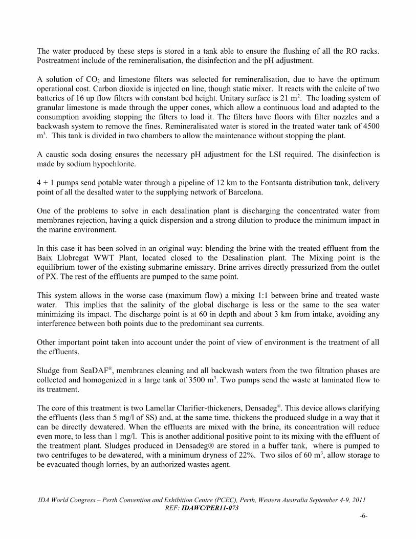
The water produced by these steps is stored in a tank able to ensure the flushing of all the RO racks. Postreatment include of the remineralisation, the disinfection and the pH adjustment.
A solution of CO2 and limestone filters was selected for remineralisation, due to have the optimum operational cost. Carbon dioxide is injected on line, though static mixer. It reacts with the calcite of two batteries of 16 up flow filters with constant bed height. Unitary surface is 21 m2. The loading system of granular limestone is made through the upper cones, which allow a continuous load and adapted to the consumption avoiding stopping the filters to load it. The filters have floors with filter nozzles and a backwash system to remove the fines. Remineralisated water is stored in the treated water tank of 4500 m3. This tank is divided in two chambers to allow the maintenance without stopping the plant.
A caustic soda dosing ensures the necessary pH adjustment for the LSI required. The disinfection is made by sodium hypochlorite.
4 + 1 pumps send potable water through a pipeline of 12 km to the Fontsanta distribution tank, delivery point of all the desalted water to the supplying network of Barcelona.
One of the problems to solve in each desalination plant is discharging the concentrated water from membranes rejection, having a quick dispersion and a strong dilution to produce the minimum impact in the marine environment.
In this case it has been solved in an original way: blending the brine with the treated effluent from the Baix Llobregat WWT Plant, located closed to the Desalination plant. The Mixing point is the equilibrium tower of the existing submarine emissary. Brine arrives directly pressurized from the outlet of PX. The rest of the effluents are pumped to the same point.
This system allows in the worse case (maximum flow) a mixing 1:1 between brine and treated waste water. This implies that the salinity of the global discharge is less or the same to the sea water minimizing its impact. The discharge point is at 60 in depth and about 3 km from intake, avoiding any interference between both points due to the predominant sea currents.
Other important point taken into account under the point of view of environment is the treatment of all the effluents.
Sludge from SeaDAF®, membranes cleaning and all backwash waters from the two filtration phases are collected and homogenized in a large tank of 3500 m3. Two pumps send the waste at laminated flow to its treatment. The core of this treatment is two Lamellar Clarifier-thickeners, Densadeg®. This device allows clarifying the effluents (less than 5 mg/l of SS) and, at the same time, thickens the produced sludge in a way that it can be directly dewatered. When the effluents are mixed with the brine, its concentration will reduce even more, to less than 1 mg/l. This is another additional positive point to its mixing with the effluent of the treatment plant. Sludges produced in Densadeg® are stored in a buffer tank, where is pumped to two centrifuges to be dewatered, with a minimum dryness of 22%. Two silos of 60 m3, allow storage to be evacuated though lorries, by an authorized wastes agent.
IDA World Congress – Perth Convention and Exhibition Centre (PCEC), Perth, Western Australia September 4-9, 2011REF: IDAWC/PER11-073
-6-

Additionally and also by the point of view of Environment and specially in renewable energies, it is necessary to underline that the desalination plant have a wind generator and all the building roofs are covered by photovoltaic panels (1300 kW in 20372 m2) able to save 850 Ton of CO2 per year.
Fig. 4 – Renewable energies in Llobregat plan
IV. MANAGEMENT CRITERIA FOR THE PRODUCTION OF THE DESALINATION PLANT
Llobregat Desalination Plant is integrated in the supply system of Barcelona area, more than 100 municipalities and more than 4,5 millions of inhabitants, together with mainly 3 drinking water plants: Cardedeu (Ter River), Abrera (Llobregat River), both managed by ATLL and Sant Joan Despí (Llobregat River and aquifer), managed by Aigües de Barcelona.
The majority of available water resources of ATLL come from the 6 dams of the Ter and Llobregat basins. The desalination plant has been taken as a new dam, with a maximum flow of 180.000 m3/day (20.000 m3/day are on spare); It will be a complement to the rest of the dams. Ta have a reference level the annual production of Llobregat plant, established in 60 hm3/year (GLY), is equivalent to the capacity of one the dams (Boadella, located in Girona).
According to that the ACA (Catalonian Agency of Water), ATLL and EMA (Environment Company of Barcelona Metropolitan Area) have established an exploitation criteria for the new infrastructures in the ATLL environment, including the Llobregat Desalination plant:
- Optimize the reservoirs use and aquifer of Llobregat Basin and reducing the contribution of them from Ter basin (to supply Girona region).- Incorporate the water from the Llobregat Desal Plant to generate a preventive saving of the dam flows.- Introduce the new treatments (EDR and RO) from the PWT Plants of Llobregat (Abrera and Sant Joan Despí) and from Llobregat Desalination Plant to improve the quality of the supplied water.
In the practice for the PWTP is a quality criterion according to the raw water characteristics, to establish the number of trains of EDR or BWRO being in service in those plants.
IDA World Congress – Perth Convention and Exhibition Centre (PCEC), Perth, Western Australia September 4-9, 2011REF: IDAWC/PER11-073
-7-

For the Desalination Plant is a quantity criterion depending of the average level of Ter and Llobregat dams:
- Dams level ≥ 80%; Desalination Plant at minimum production: 1 train, 20.000 m3/day- Dams level ≤ 60%; Desalination Plant at maximum production: 9 trains, 180.000 m3/day- Level between 60 and 80%; number of running trains according with the curve of fig.5.- The remaining 10th train will be on standby to be used when other train is on cleaning or maintenance. It also would be used in case of minimum levels of the dams.
These instructions are given by ACA every two weeks according with average dam levels of the revision day. From November 2009 the plant has been running with these criteria, the first months it was running from 10 to 50%, but from April 2010 the plant is running at minimum production. The year 2010 and the beginning of 2011 were very rainy, as you can see in the fig. 6 where is indicated the level of the dam Sau one of the more important in the basin.
From the data of the averages of the reservoirs levels during the last 10 years it is possible to simulate the “average year”, but it will be not the most probable. This is due to the large variability in the pluviometry of the Mediterranean climate, being the filling of the reservoirs normally to catastrophic episodes of rains (high intensity and short duration), given in different times of the year (with a bigger variation in the last years). All this makes practically impossible to predict the desalination operation in medium term; but the operation regimen can be established in dried times, because the emptying of the reservoirs can be determined with elevated grade of accuracy depending on the available statistical parameters.
Fig. 5 – Curve for Desalination Plant operation
IDA World Congress – Perth Convention and Exhibition Centre (PCEC), Perth, Western Australia September 4-9, 2011REF: IDAWC/PER11-073
-8-
Explotation criteria for Llobregat Desalination Plant
0%
10%
20%
30%
40%
50%
60%
70%
80%
90%
100%
0 20.000 40.000 60.000 80.000 100.000 120.000 140.000 160.000 180.000 200.000
Production Llobregat Desalination Plant (m3/day)
Avera
ge v
olu
me T
er-
Llo
bre
gat d
am
s

Fig. 6 – Level of Sau Dam and average of 10 years
As an example of Mediterranean climate you can see in fig.7 what could have been the Desalination production in the years 2007 to 2009 where Barcelona area passed from a severe drought to a heavy rainy period. The green line was the real volume of the dams, the red line the Desalination production. The blue line simulates the volume of water in the dams if the desalination plant was operating in these conditions.
Simulación régimen ITAM vs. Embalses 2007-2009
10,00
20,00
30,00
40,00
50,00
60,00
70,00
80,00
90,00
100,00
01-0
1-07
31-0
1-07
02-0
3-07
01-0
4-07
01-0
5-07
31-0
5-07
30-0
6-07
30-0
7-07
29-0
8-07
28-0
9-07
28-1
0-07
27-1
1-07
27-1
2-07
26-0
1-08
25-0
2-08
26-0
3-08
25-0
4-08
25-0
5-08
24-0
6-08
24-0
7-08
23-0
8-08
22-0
9-08
22-1
0-08
21-1
1-08
21-1
2-08
20-0
1-09
19-0
2-09
21-0
3-09
20-0
4-09
20-0
5-09
19-0
6-09
19-0
7-09
18-0
8-09
17-0
9-09
17-1
0-09
16-1
1-09
16-1
2-09
% Ter-Llobregat
0
20.000
40.000
60.000
80.000
100.000
120.000
140.000
160.000
180.000
200.000
Producción ITAM (m3/dia)
Sim ulación Ter-Llobregat con ITAM (%) Volum en real Ter-Llobregat s in ITAM (%) Modulación ITAM
Fig. 7 – Simulation of Plant operation in the years 2007 to 2009
IDA World Congress – Perth Convention and Exhibition Centre (PCEC), Perth, Western Australia September 4-9, 2011REF: IDAWC/PER11-073
-9-

V. OPERATIONAL RESULTS
The quality of sea water is quite stable throughout the time, confirming and overcoming the established forecasts in the previous studies which determined the location of intake point.
The evolution in a year and a half of three important parameters can see at Fig.8. Together with the seawater pH we can follow the temperature and the Turbidity, both very important due to the impact in Boron rejection and the pretreatment.
Seawater Parameters (I)
0
5
10
15
20
25
30
01/01
/2010
11/04
/2010
20/07
/2010
28/10
/2010
05/02
/2011
16/05
/2011
NTU
/ºC
7,4
7,6
7,8
8
8,2
8,4
8,6
Turbidity Temperature pH
Fig.8 – Seawater parameters: Turbidity, Temperature and pH
The pH values and sea water conductivity are very stable through the time, as expected. In the year 2010 the statistic values of these two parameters are:
pH Conductivity (µS/cm at 25ºC)Medium 8,11 56.390Stand. Desv. 0,109 831,5
Other parameters of seawater quality are conductivity, chlorine, sodium and boron. Their evolution can see at Fig.9
IDA World Congress – Perth Convention and Exhibition Centre (PCEC), Perth, Western Australia September 4-9, 2011REF: IDAWC/PER11-073
-10-

Seawater Parameters (II)
0
10.000
20.000
30.000
40.000
50.000
60.000
70.000
80.000
ene-10 abr-10 jul-10 oct-10 feb-11 may-11
µS/cmmg/l
0
1
2
3
4
5
6
mg/l (Boron)
Conductivity a 25ºC Chlorine Sodium Boron
Fig.9 – Seawater parameters: Conductivity, Chlorine, Sodium, and Boron
The SDI evolution through the pretreatment, in the year 2010, is shown in the fig.10:
0
5
10
15
20
25SDI Evolution - 2010
Agua bruta Entrada F. Cerrados A Salida F. Cerrados A Salida F. Cartuchos A
Entrada F. Cerrados B Salida F. Cerrados B Salida F. Cartuchos B
Fig.10 – 2010 SDI Evolution in the Pretreatment
IDA World Congress – Perth Convention and Exhibition Centre (PCEC), Perth, Western Australia September 4-9, 2011REF: IDAWC/PER11-073
-11-
Despite part of the time it has not be necessary the use of SeaDAF® or the first stage of dual media filters the results of pretreatment have been very good, better than those we had during the three years of piloting. Most of the time the SDI incoming to RO is less than 2.5 %/min. Also the Turbidity after Cartridge Filters is very low being less than 0.1 NTU most of the time.
The optimised criteria to operate the pretreatment are related to seawater quality, mainly SDI, Turbidity and OM. The SeaClean® dual media pressurized filters should be always running, the second to enter in operation should be the Floatation SeaDAF® and the third the Mediazur® gravity filtration. But the flexibility of design allows also to keep running 2 or 3 stages using fewer chemicals; it is a decision of the operators. Both systems have demonstrated good results. Until today the worse design case has not been arrived.
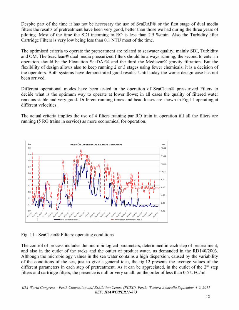
Different operational modes have been tested in the operation of SeaClean® pressurized Filters to decide what is the optimum way to operate at lower flows; in all cases the quality of filtered water remains stable and very good. Different running times and head losses are shown in Fig.11 operating at different velocities.
The actual criteria implies the use of 4 filters running par RO train in operation till all the filters are running (5 RO trains in service) as more economical for operation.
Fig. 11 - SeaClean® Filters: operating conditions
The control of process includes the microbiological parameters, determined in each step of pretreatment, and also in the outlet of the racks and the outlet of product water, as demanded in the RD140/2003. Although the microbiology values in the sea water contains a high dispersion, caused by the variability of the conditions of the sea, just to give a general idea, the fig.12 presents the average values of the different parameters in each step of pretreatment. As it can be appreciated, in the outlet of the 2nd step filters and cartridge filters, the presence is null or very small, on the order of less than 0,5 UFC/ml.
IDA World Congress – Perth Convention and Exhibition Centre (PCEC), Perth, Western Australia September 4-9, 2011REF: IDAWC/PER11-073
-12-
PRESIÓN DIFERENCIAL FILTROS CERRADOS
0,0
0,1
0,2
0,3
0,4
0,5
0,6
0,7
0,8
0,9
1,0
01-1
0-09
11-1
0-09
21-1
0-09
31-1
0-09
10-1
1-09
20-1
1-09
30-1
1-09
10-1
2-09
20-1
2-09
30-1
2-09
09-01
-10
19-0
1-10
29-01
-10
08-0
2-10
18-02
-10
28-0
2-10
10-03
-10
20-0
3-10
30-03
-10
09-0
4-10
19-04
-10
29-0
4-10
09-0
5-10
19-05
-10
29-0
5-10
Fecha
bar
0,00
2,00
4,00
6,00
8,00
10,00
12,00
14,00
16,00
m/h
dP F. Cerrada Línea A Velocidad de filtración Línea A

MICROBIOLOGY IN PRETREATMENT 2010-2011
0,00
5,00
10,00
15,00
20,00
25,00
30,00
35,00
40,00
45,00
50,00
Seawate
r
Floata
ted
Filter
s 1st
Filter
s 2on
Cartrid
ge
UFC
/100
ml (
exce
pt A
erob
.)
0,00
20,00
40,00
60,00
80,00
100,00
120,00
140,00
160,00
180,00
200,00
Alg
ae (c
els/
ml)
Aerob. Tot. 22ºC
Colif. Tot.
Escherichia Coli
C. Prefringens
Enterococos
Algae
Fig. 12 – Microbiology in Pretreatment
The efficiency in algae removal is been studied now.
From the commissioning, due to operating conditions indicated by ACA, the plant has been operated with a variable number of trains, from 1 up to 5, with rotation between the racks on service. Due to that the data shown below has a large dispersion, because there are linked results between one rack and the results of other racks. The Fig. 13 and 14 show the evolution of feed pressure and Permeate Conductivity vs. seawater temperature.
Parámetros OI
0
100
200
300
400
500
600
01-ene-10 21-ene-10 10-feb-10 02-mar-10 22-mar-10 11-abr-10 01-may-10 21-may-10
microS/cm
10
12
14
16
18
20
22
24
ºC
Conductividad permeado T entrada rack
Fig. 13 & 14 – RO feed pressure and permeate Conductivity vs. water temperature
Typical operational parameters of a first pass train are presented in Fig.15. The data are from the rack number 10. We can also see the parameters of Energy Recovery: conductivities at inlets and outlets and head losses; all ERI parameters are under the guaranteed figures. It is also important underlines the elevated back pressure of PX due to the direct reject of brine to the WWTP equilibrium tower where is blended with the treated effluent.
IDA World Congress – Perth Convention and Exhibition Centre (PCEC), Perth, Western Australia September 4-9, 2011REF: IDAWC/PER11-073
-13-
10
12
14
16
18
20
22
24
56.0
58.0
60.0
62.0
64.0
66.0
68.0
22/03/2010 11/04/2010 01/05/2010 21/05/2010 10/06/2010 30/06/2010 20/07/2010
Temperature (ºC)
P feed (bar)
RO Parameters

Fig. 15- 10th RO train typical parameters, May 2010
The average efficient of Pressure Exchanges, PX-220, has been 96.5%, calculated under the formula establish by ERI.The specific energy consumption is under the guaranteed values. The average of the year 2010 splited by Pretreatment, RO, Treated Water Pumping, Chemicals and Sludge Treatment and Auxiliary Systems is presented in Fig.16. It is the total energy used to put the water in Fonsanta Reservoir, 3.67 kW.h/m3.
0.456; 12.41%
2.595; 70.68%
0.287; 7.81%0.108; 2.95%0.225; 6.14%
Energy Consumption Average Year 2010
3.671 kW.h/m3
Intake & PretreatmentReverse OsmosisTreated Water PumpsChemicals & sludgeAuxiliary Systems
kW.h/m3 ; %
Fig. 16 – Energy Consumption in 2010
The parameters of treated water are also under expectations and guaranteed values as it can be seen in Fig. 17 to 22.
IDA World Congress – Perth Convention and Exhibition Centre (PCEC), Perth, Western Australia September 4-9, 2011REF: IDAWC/PER11-073
-14-

Fig. 17- Potable Water Conductivity Fig. 18- Potable Water pH
Fig. 19- Potable Water Turbidity Fig. 20- Potable Water LSI
Fig. 21- Potable Water Alkalinity Fig. 22- Calcium in Potable Water
IDA World Congress – Perth Convention and Exhibition Centre (PCEC), Perth, Western Australia September 4-9, 2011REF: IDAWC/PER11-073
-15-
Conductivity
0
100
200
300
400
500
600
700
800
900
01-01-10 02-03-10 01-05-10 30-06-10 29-08-10 28-10-10 27-12-10 25-02-11 26-04-11
mic
ro-S
/cm
a 2
0ºC
pH
7,50
7,70
7,90
8,10
8,30
8,50
8,70
8,90
1-1-10 2-3-10 1-5-10 30-6-10 29-8-10 28-10-10 27-12-10 25-2-11 26-4-11
Turbidity
0,00
0,20
0,40
0,60
0,80
1,00
1,20
1,40
1,60
1,80
2,00
01-01-10 02-03-10 01-05-10 30-06-10 29-08-10 28-10-10 27-12-10 25-02-11 26-04-11
NTU
LSI
-1,000
-0,800
-0,600
-0,400
-0,200
0,000
0,200
0,400
01-01-10 11-04-10 20-07-10 28-10-10 05-02-11 16-05-11
Alkalinity
0,0
10,0
20,0
30,0
40,0
50,0
60,0
70,0
80,0
90,0
100,0
01-01-10 02-03-10 01-05-10 30-06-10 29-08-10 28-10-10 27-12-10 25-02-11 26-04-11
mg
CaC
O3/l
Calcium
10,0
12,0
14,0
16,0
18,0
20,0
22,0
24,0
26,0
28,0
30,0
01-01-10 02-03-10 01-05-10 30-06-10 29-08-10 28-10-10 27-12-10 25-02-11 26-04-11
Boron
0,500
0,600
0,700
0,800
0,900
1,000
1,100
1,200
1,300
1,400
1,500
01-01-10 02-03-10 01-05-10 30-06-10 29-08-10 28-10-10 27-12-10 25-02-11 26-04-11
mg/l

Fig. 23- Boron in Potable Water
The conductivity shows the expected values for the remineralised desalted water. As for the boron, the outlet concentration has kept below 1 mg/l, due to NaOH dosing in the feeding to the first pass racks over 17ºC, and in august starting a second pass train.
The LSI has been progressively adjusting to locate it in positive values, to get it the NaOH has been dosed in the outlet of product water, once all parameters of up flow remineralising filters has been optimised. The same effect can be observed in pH, alkalinity and Calcium results. The alkalinity shows very acceptable values, over60 mgCaCO3/l. In August a cost optimisation was done reducing the CO2
dose rate and increasing the caustic.
Generally speaking the up flow Filters presents good results. The turbidity at plant outlet remains stable below 1 NTU, with the exception of some sporadic episodes, with no ordinary manoeuvres carried out in the remineralisation installation.
The product water of the Llobregat Desalination Plant is getting the expected quality, and also excellent organoleptic characteristics.
VI. CONCLUSIONS
The Llobregat Desalination plant is the largest sea water plant in operation in Europe to human supply and one of the largest in the world.Together with all works taken by ATLL it has become the key element to ensure the water supply in the area of Barcelona in the most severe droughts and its design has been made to work in the most unfavourable conditions.
The tight construction and its innovations have made it has awarded the prize of the Desalination Plant of the Year in the Global Water Awards 2010, being classified as the flagship of the desalination in Spain.
Llobregat Desalination Plant has fulfilled the expected objectives of operation and quality of treated water since the inauguration in July 2009, despite the reduced regime of operation due to the high level of the dams in this period.
VII. REFERENCES
1. Miguel Angel Sanz, Tomás Cazurra, Carlos Miguel; Barcelona: 200000 m3/day of Potable Water coming from Mediterranean Sea, MP07-056, IDA Congress 2007, Mas Palomas2. Miguel Angel Sanz, Gerardo Cremer; 4 Stages Pre-treatment Reverse Osmosis for South-Pacific Seawater: El Coloso Plant (Chile), SP05-154, IDA Congress 2005, Singapur3. Veronique Bonnelye, M. A. Sanz; RO Pre-Treatment: High Rate Flotation to Face Bad Seawater Conditions, SP05-086, IDA Congress 2005, Singapore4. Miguel Angel Sanz, Rick Stover; Low Energy Consumption in the Perth Seawater Desalination Plant, MP07-111, IDA Congress 2007, Mas Palomas
IDA World Congress – Perth Convention and Exhibition Centre (PCEC), Perth, Western Australia September 4-9, 2011REF: IDAWC/PER11-073
-16-