Two-Way Flat Plate Concrete Floor System Analysis and Design · Two-Way Flat Plate Concrete Floor...
67
Version: Jul-11-2018 Two-Way Flat Plate Concrete Floor System Analysis and Design
Transcript of Two-Way Flat Plate Concrete Floor System Analysis and Design · Two-Way Flat Plate Concrete Floor...

Version: Jul-11-2018
Two-Way Flat Plate Concrete Floor System Analysis and Design

Version: Jul-11-2018
Two-Way Flat Plate Concrete Floor System Analysis and Design
The concrete floor slab system shown below is for an intermediate floor to be designed considering partition weight
= 1 kN/m2, and unfactored live load = 1.9 kN/m2 . Flat plate concrete floor system does not use beams between
columns or drop panels and it is usually suited for lightly loaded floors with short spans typically for residential and
hotel buildings. The lateral loads are independently resisted by shear walls. The two analysis procedures prescribed in
CSA A23.3-14 Direct Design Method (DDM) and Elastic Frame Method (EFM) are illustrated in detail in this
example. The hand solution from EFM is also used for a detailed comparison with the analysis and design results of
the engineering software program spSlab.
Figure 1 - Two-Way Flat Concrete Floor System
Version: Jul-11-2018
Contents
1. Preliminary Member Sizing ..................................................................................................................................... 1
2. Two-Way Slab Analysis and Design ........................................................................................................................ 4
2.1. Direct Design Method (DDM) .......................................................................................................................... 5
2.1.1. Direct design method limitations ............................................................................................................ 5
2.1.2. Design moments ..................................................................................................................................... 5
2.1.3. Flexural reinforcement requirements...................................................................................................... 6
2.1.4. Factored moments in columns ................................................................................................................ 8
2.2. Elastic Frame Method (EFM) ........................................................................................................................... 9
2.2.1. Elastic frame method limitations .......................................................................................................... 10
2.2.2. Frame members of elastic frame .......................................................................................................... 10
2.2.3. Elastic frame analysis ........................................................................................................................... 12
2.2.4. Design moments ................................................................................................................................... 13
2.2.5. Distribution of design moments ........................................................................................................... 15
2.2.6. Flexural reinforcement requirements.................................................................................................... 15
2.2.7. Column design moments ...................................................................................................................... 17
3. Design of Interior, Edge, and Corner Columns ...................................................................................................... 19
3.1. Determination of factored loads ...................................................................................................................... 20
3.2. Column Capacity Diagram (Axial-Moment Interaction Diagram) ................................................................. 21
4. Two-Way Slab Shear Strength ............................................................................................................................... 25
4.1. One-Way (Beam action) Shear Strength ........................................................................................................ 25
4.2. Two-Way (Punching) Shear Strength ............................................................................................................ 26
5. Two-Way Slab Deflection Control (Serviceability Requirements) ........................................................................ 29
5.1. Immediate (Instantaneous) Deflections ........................................................................................................... 29
5.2. Time-Dependent (Long-Term) Deflections .................................................................................................... 39
6. Computer Program Solution ................................................................................................................................... 40
7. Summary and Comparison of Two-Way Slab Design Results ............................................................................... 60
8. Deflection Calculation Methods ............................................................................................................................. 62
9. Comparison of Two-Way Slab Analysis and Design Methods .............................................................................. 62

1
Code
Design of Concrete Structures (CSA A23.3-14)
Reference
CAC Concrete Design Handbook, 4th Edition, Cement Association of Canada
Notes on ACI 318-11 Building Code Requirements for Structural Concrete, Twelfth Edition, 2013 Portland
Cement Association, Example 20.1
Design Data
Floor-to-Floor Height = 2.75 m (provided by architectural drawings)
Superimposed Dead Load, SDL = 21 kN/m for framed partitions, wood studs plaster 2 sides
Live Load, 2LL = 1.9 kN/m for Residential floors
'f 28 MPac (for slabs)
'f 42 MPac (for columns)
'f 400 MPay
Required fire resistance rating = 2 hours
Solution
1. Preliminary Member Sizing
a. Slab minimum thickness - Deflection CSA A23.3-14 (13.2)
In this example deflection will be calculated and checked to satisfy project deflection limits. Minimum
member thickness and depths from CSA A23.3-14 will be used for preliminary sizing.
Using CSA A23.3-14 minimum slab thickness for two-way construction without interior beams in Section
13.2.3.
Exterior Panels:
,min
0.6 /10001.1 187 mm
30
n y
s
l fh
CSA A23.3-14 (13.2.3)
But not less than 120 mm. CSA A23.3-14 (13.2.1)
Interior Panels:
,min
0.6 /1000170 mm
30
n y
s
l fh
CSA A23.3-14 (13.2.3)
But not less than 120 mm. CSA A23.3-14 (13.2.1)
Wherenl length of clear span in the long direction = 5500 – 400 = 5100 mm
Try 190 mm slab for all panels (self-weight 24.56 kN/m )

2
b. Slab shear strength – one way shear
Evaluate the average effective depth (Figure 2):
16190 20 16 146 mm
2 2
b
l slab clear b
dd t c d
16190 20 162 mm
2 2
bt slab clear
dd t c
146 162154 mm
2 2
l tavg
d dd
Where:
cclear = 20 mm for 15M steel bar CSA A23.3-14 (Annex A. Table 17)
db = 16 mm for 15M steel bar
Figure 2 - Two-Way Flat Concrete Floor System
Load Combination 1:
Factored dead load, 21.4 (4.56 1) 7.78 kN/mdfw CSA A23.3-14 (Annex C. Table C.1 a)
Total factored load 27.78 kN/mfw
Load Combination 2:
Factored dead load, 21.25 (4.56 1) 6.95 kN/mdfw
Factored live load, 21.5 1.9 2.85 kN/mlfw CSA A23.3-14 (Annex C. Table C.1 a)
Total factored load 29.8 kN/mfw (Controls)
Check the adequacy of slab thickness for beam action (one-way shear) CSA A23.3-14 (13.3.6)
at an interior column:
The critical section for one-way shear is extending in a plane across the entire width and located at a distance,
dv from the face of support or concentrated load (see Figure 3). CSA A23.3-14 (13.3.6.1)
Consider a 1 m. wide strip.

3
Tributary area for one-way shear is
2
2
5,500 400139 1,000
2 22.41 m
1,000TributaryA
9.8 2.41 23.63 kNf f TributaryV w A
' c c c w vV f b d CSA A23.3-14 (Eq. 11.6)
Where:
1 for normal weight concrete CSA A23.3-14 (8.6.5)
0.21 for slabs with overall thickness not greater than 350 mm CSA A23.3-14 (11.3.6.2)
Max (0.9 ,0.72 ) Max (0.9 154,0.72 190) 139 mmv avgd d h CSA A23.3-14 (3.2)
' 5.29 MPa 8 MPacf CSA A23.3-14 (11.3.4)
1390.65 1 0.21 28 1,000 100.4 kN
1,000cV
uV
Slab thickness of 190 mm is adequate for one-way shear.
c. Slab shear strength – two-way shear
Check the adequacy of slab thickness for punching shear (two-way shear) at an interior column (Figure 4):
Shear prerimeter: 0 2 (400 400 2 154) 2,216 mmb CSA A23.3-14 (13.3.3)
Tributary area for two-way shear is 2
2400 1545.5 4.2 22.79 m
1,000TributaryA
The factored resisiting shear stress, Vr shall be the smallest of : CSA A23.3-14 (13.3.4.1)
a) '2 21 0.19 1 0.19 0.65 28 1.96 MPa
1r c c c
c
v v f
b) ' 4 1540.19 0.19 1 0.65 28 1.61 MPa
2216
s
r c c c
o
dv v f
b
c) '0.38 0.38 1 0.65 28 1.31 MPar c c cv v f
,
223.37 kN1,000 0.655 MPa
2,216 154
f
f aveo
VV
b d

4
,
2 1.2r
f ave
V
V CAC Concrete Design Handbook 4th Edition (5.2.3)
Slab thickness of 190 mm is adequate for two-way shear.
d. Column dimensions - axial load
Check the adequacy of column dimensions for axial load:
Tributary area for interior column is 2(5.5 4.2) 23.1 mTributaryA
9.8 23.1 226.38 kNf f TributaryP w A
,max (0.2 0.002 ) 0.80r ro roP h P P (For tied column along full length) CSA A23.3-14 (Eq. 10.9)
'
1 ( ) f Aro c c g st t p s y st y t pr pP f A A A A F A f A CSA A23.3-14 (Eq. 10.11)
0.808 0.65 28 (400 400 0) 0.85 420 0 0 23,528,960 N =2,352.9 kNroP
,max (0.2 0.002 400) 2,352.9 0.80 2,352.9rP
,max 1,882.32 kN r fP P
'
1 0.85 0.0015 0.85 0.0015 28 0.808 0.67cf CSA A23.3-14 (Eq. 10.1)
Column dimensions of 400 mm×400 mm are adequate for axial load.
2. Two-Way Slab Analysis and Design
CSA A23.3 states that a regularslab system may be designed using any procedure satisfying conditions of
equilibrium and compatibility with the supports, provided that it is shown that the factored resistance at every
section is at least equal to the effects of the factored loads and that all serviceability conditions, including specified
limits on deflections, are met. CSA A23.3-14 (13.5.1)
Figure 4 – Critical Section for Two-Way
Shear
Figure 3 – Critical Section for One-Way
Shear

5
CSA A23.3 permits the use of Plastic Plate Theory Method (PPTM), Theorems of Plasticity Method (TPM),
Direct Design Method (DDM) and Elastic Frame Method (EFM); known as Equivalent Frame Method in the
ACI; for the gravity load analysis of orthogonal frames. The following sections outline the solution per DDM,
EFM, and spSlab software respectively.
2.1. Direct Design Method (DDM)
Two-way slabs satisfying the limits in CSA A23.3-14 (13.9) are permitted to be designed in accordance with
the DDM.
2.1.1. Direct design method limitations
There shall be a minimum of three continuous spans in each direction (3 spans) CSA A23.3-14 (13.9.1.2)
Successive span lengths centre-to-centre of supports in each direction shall not differ by more than one- third
of the longer span (span lengths are equal) CSA A23.3-14 (13.9.1.3)
All loads shall be due to gravity only and uniformly distributed over an entire panel (Loads are uniformly
distributed over the entire panel) CSA A23.3-14 (13.9.1.4)
The factored live load shall not exceed twice the factored dead load (Service live-to-dead load ratio of 0.41
< 2.0) CSA A23.3-14 (13.9.1.4)
Since all the criteria are met, Direct Design Method can be utilized.
2.1.2. Design moments
a. Calculate the total factored static moment:
2 22 9.8 4.2 5.1
133.82 kN.m8 8
f a n
o
wM
CSA A23.3-14 (13.9.1.4)
Distribute the total factored moment, oM , in an interior and end span: CSA A23.3-14 (13.9.3.1 &13.9.3.2)
Table 1 - Distribution of Mo along the span
Location Total Design Strip Moment,
MDES (kN.m)
Exterior Span
Exterior Negative 0.26 × Mo = 34.8
Positive 0.52 × Mo = 69.6
Interior Negative 0.70 × Mo = 93.68
Interior Span Positive 0.35 × Mo = 46.8
b. Calculate the column strip moments. CSA A23.3-14 (13.11.2)
That portion of negative and positive factored moments not resisted by column strips shall be proportionately
assigned to corresponding half middle strips. CSA A23.3-14 (13.11.3.1)

6
Table 2 - Lateral Distribution of the Total Design Strip Moment, MDES
Location
Total Design
Strip
Moment,
(kN.m)
Column Strip
Moment, (kN.m)
Moment in Two
Half Middle Strips,
(kN.m)
Exterior Span
Exterior
Negative* 34.8 1.00 × MDES = 34.8 0.00 × MDES = 0.0
Positive 69.6 0.6 × MDES = 41.8 0.4 × MDES = 27.8
Interior
Negative* 93.68 0.8 × MDES = 74.94 0.2 × MDES = 18.7
Interior Span Positive 46.8 0.6 × MDES = 28.1 0.4 × MDES = 18.7 * All negative moments are at face of support.
2.1.3. Flexural reinforcement requirements
a. Determine flexural reinforcement required for column and middle strips at all critical sections
The following calculation is for the exterior span exterior negative location of the column strip.
Reinforcement for the total factored negative moment transferred to the exterior columns shall be placed
within a band width bb. Temperature and shrinkage reinforcment determined as specified in clause 7.8.1 shall
be provided in that sectopm pf the slab outside of the bad region defined by bb or as required by clause
13.10.9. CSA A23.3-14 (13.10.3)
34.8 kN.mfM
Use average davg = 154 mm
In this example, jd will be assumed to taken equal to 0.98d. The assumptions will be verified once the area
of steel in finalized.
Assume 0.98 150.9 mmjd d
Column strip width, 4,200 / 2 2,100 mmb
Middle strip width, 4,200 2,100 2,100 mmb
6234.8 10
678 mm0.85 400 0.95 150.9
f
s
s
MA
f jdy
'
1 0.85 0.0015 0.80 0.67cf CSA A23.3-14 (10.1.7)
2700 4005.29 mm
0.9 ' 0.9 28 2,100
s y
c
A fa
f b
2
1
0.85 2834 400Recalculate ' ' for the actual 2834 mm 11.81 mm
' 0.65 0.80 35 4,500
s s y
s
c c
A fa A a
f b
0.982
ajd d d
Therefore, the assumption that jd equals to 0.98d is valid.
Min2 20.002 0.002 190 2,100 = 798 mm 676.24 mms gA A CSA A23.3-14 (7.8.1)
Provide 4 - 15M bars concentrated within the band bb (800 mm2 > 798 mm2)
Maximum spacing: CSA A23.3-14 (13.10.4)
7
Negative reinforcement in the band definded by bb:
1.5 285 mm 250 mmsh
Remaining negative moment reinforcement (reinforcement for column strip that is not included in
the band bb):
3 570 mm 500 mmsh
For the exterior negative reinforcements within the band bb, the maximum spacing is 250 mm. To distribute
the bars uniformly, the maximum spacing in the band bb is applied along the whole column strip.
Provide 9 - 15M bars with 2200 mmsA and max2,100 / 9 233 mm < s s
Note that the number of bars for this section is governed by the maximum spacing allowed by the code.
Based on the procedure outlined above, values for all span locations are given in Table 3.
Table 3 - Required Slab Reinforcement for Flexure (DDM)
Span Location Mf
(kN.m)
b
(m)
d
(mm)
As Req’d for
flexure (mm2)
Min As
(mm2)
Reinforcement
Provided
As Prov. for
flexure (mm2)
End Span
Column
Strip
Exterior Negative 34.80 2.1 154 678 798 9 – 15 M 1,800
Positive 41.80 2.1 154 823 798 6 – 15 M 1,200
Interior Negative 74.94 2.1 154 1,513 798 8 – 15 M 1,600
Middle
Strip
Exterior Negative 0.00 2.1 154 0 798 6 – 15 M 1,200
Positive 27.80 2.1 154 541 798 6 – 15 M 1,200
Interior Negative 18.70 2.1 154 362 798 6 – 15 M 1,200
Interior Span
Column
Strip Positive 28.10 2.1 154 548 798 6 – 15 M 1,200
Middle
Strip Positive 18.70 2.1 154 362 798 6 – 15 M 12,00
b. Calculate additional slab reinforcement at columns for moment transfer between slab and column
When gravity load, wind, earthquake, or other lateral forces cause transfer of moment between slab and
column, a fraction of unbalanced moment given by f shall be transferred by flexural reinforcement placed
within a width bb. CSA A23.3-14 (13.10.2)
1 2
11
21
3
f v
b b
Where
b1 = Width width of the critical section for shear measured in the direction of the span for which moments
are determined according to CSA A23.3-14, clause 13 (see Figure 5).
b2 = Width of the critical section for shear measured in the direction perpendicular to b1 according to CSA
A23.3-14, clause 13 (see Figure 5).
bb = Effective slab width = 2 3 sc h CSA A23.3-14 (3.2)

8
Figure 5 – Critical Shear Perimeters for Columns
Table 4 - Additional Slab Reinforcement required for moment transfer between slab and column (DDM)
Span Location Mf
*
(kN.m) γf
γf Mf
(kN.m)
Effective
slab
width, bb
(mm)
d
(mm)
As req’d
within bb
(mm2)
As prov. For
flexure within bb
(mm2)
Add’l
Reinf.
End Span
Column Strip Exterior Negative 34.8 0.62 21.5 970 154 420 1,000 -
Interior Negative 0.0 0.60 0.0 970 154 0.0 800 -
*Mf is taken at the centerline of the support in Equivalent Frame Method solution.
2.1.4. Factored moments in columns
a. Interior columns:
2 ' ' ' 2
2 20.07 0.5 ( )f df lf a n df a nM w w l l w l l CSA A23.3-14 (13.9.4)
2 20.07 6.95 0.5 2.85 4.2 5.1 6.95 4.2 5.1 10.9 kN.m
With the same column size and length above and below the slab,
10.95.45 kN.m
2columnM
b. Exterior Columns:
9
Total exterior negative moment from slab must be transferred directly to the column: 34.8 kN.mfM With
the same column size and length above and below the slab,
34.817.4 kN.m
2columnM
The moments determined above are combined with the factored axial loads (for each story) for design of
column sections as shown later in this example.
2.2. Elastic Frame Method (EFM)
EFM (as known as Equivalent Frame Method in the ACI 318) is the most comprehensive and detailed procedure
provided by the CSA A23.3 for the analysis and design of two-way slab systems where these systems may, for
purposes of analysis, be considered a series of plane frames acting longitudinally and transversely through the
building. Each frame shall be composed of equivalent line members intersecting at member centrelines, shall
follow a column line, and shall include the portion of slab bounded laterally by the centreline of the panel on
each side. CSA A23.3-14 (13.8.1.1)
Probably the most frequently used method to determine design moments in regular two-way slab systems is to
consider the slab as a series of two-dimensonal frames that are analyzed elastically. When using this analogy,
it is essential that stiffness properties of the elements of the frame be selected to properly represent the behavior
of the three-dimensional slab system.
In a typical frame analysis it is assumed that at a beam-column cconnection all members meeting at the joint
undergo the same rotaion. For uniform gravity loading this reduced restrtaint is accounted for by reducing the
effective stiffness of the column by either Clause 13.8.2 or Clause 13.8.3. CSA A23.3-14 (N.13.8)
Each floor and roof slab with attached columns may be analyzed separately, with the far ends of the columns
considered fixed. CSA A23.3-14 (13.8.1.2)
The moment of inertia of column and slab-beam elements at any cross-section outside of joints or column
capitals shall be based on the gross area of concrete at that section. CSA A23.3-14 (13.8.2.5)
An equivalent column shall be assumed to consist of the actual columns above and below the slab- beam plus
an attached torsional member transverse to the direction of the span for which moments are being determined.
CSA A23.3-14 (13.8.2.5)

10
2.2.1. Elastic frame method limitations
In EFM, live load shall be arranged in accordance with 13.8.4 which requires slab systems to be analyzed
and designed for the most demanding set of forces established by investigating the effects of live load placed
in various critical patterns. CSA A23.3-14 (13.8.4)
Complete analysis must include representative interior and exterior equivalent elastic frames in both the
longitudinal and transverse directions of the floor. CSA A23.3-14 (13.8.1.1)
Panels shall be rectangular, with a ratio of longer to shorter panel dimensions, measured center-to-center of
supports, not to exceed 2. CSA A23.3-14 (3.1a)
For slab systems with beams between sypports, the relative effective stiffness of beams in the two directions
is not less than 0.2 or greater than 2. CSA A23.3-14 (3.1b)
Column offsets are not greater than 20% of the span (in the direction of offset) from either axis between
centerlines of successive columns. CSA A23.3-14 (3.1c)
The reinforcement is placed in an orthogonal grid. CSA A23.3-14 (3.1d)
2.2.2. Frame members of elastic frame
Determine moment distribution factors and fixed-end moments for the elastic frame members. The moment
distribution procedure will be used to analyze the equivalent frame. Stiffness factors k , carry over factors
COF, and fixed-end moment factors FEM for the slab-beams and column members are determined using the
design aids tables at Appendix 20A of PCA Notes on ACI 318-11. These calculations are shown below.
a. Flexural stiffness of slab-beams at both ends, Ksb
1
1
4000.073
5,500
Nc , 2
2
4000.095
4,200
Nc
For1 2F Fc c , stiffness factors, 4.13NF FNk k PCA Notes on ACI 318-11 (Table A1)
Thus, 1 1
4.13cs s cs ssb NF
E I E IK k PCA Notes on ACI 318-11 (Table A1)
93 62.4 10
4.13 26,739 10 48.2 10 N.m5,500
sbK
where, 3
9 434,200(190)
2.4 10 mm12 12
ss
hI
1.5
'(3,300 6,900)2,300
c
cs cE f
CSA A23.3-14(8.6.2.2 )
1.5
2,447(3,300 28 6,900) 26,739 MPa
2,300csE
Carry-over factor COF 0.509 PCA Notes on ACI 318-11 (Table A1)
Fixed-end moment FEM 2
2 10.0843 uw PCA Notes on ACI 318-11 (Table A1)
11
b. Flexural stiffness of column members at both ends, Kc
Referring to Table A7, Appendix 20A, 95 mmat , 95 mmbt ,
ac
cb
t H H 2.75 m = 2,750 mm, t 190 mm, H 2560 mm, 1, 1.07
t H
Thus, 4.74AB BAk k by interpolation.
4.74 cc c
c
c
E IK PCA Notes on ACI 318-11 (Table A7)
93 62.13 10
4.74 31,047 10 114 10 N.m2,750
cK
Where 4 4
9 4(400)2.13 10 mm
12 12c
cI
1.5
'(3,300 6,900)2,300
c
cs cE f
CSA A23.3-14(8.6.2.2)
1.5
2,447(3,300 42 6,900) 31,047 MPa
2,300csE
2.75 m = 2,750 mmc
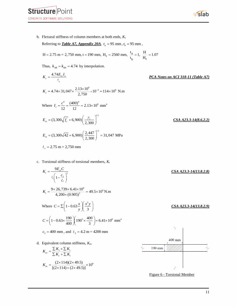
c. Torsional stiffness of torsional members, Kt
3
2
9
1
cs
t
t
t
E CK
c
CSA A23.3-14(13.8.2.8)
66
3
9 26,739 6.41 1049.5 10 N.m
4,200 (0.905)tK
Where 3
1 0.633
x x yC
y
CSA A23.3-14(13.8.2.9)
3 8 4190 4001 0.63 190 6.41 10 mm
400 3C
2 400 mmc , and 2 4.2 m = 4200 mm
d. Equivalent column stiffness, Kec
c tec
c t
K KK
K K
6(2 114)(2 49.5)10
[(2 114) (2 49.5)]ecK
Figure 6 - Torsional Member

12
6 69.1 10 N.mecK
WheretK is for two torsional members one on each side of the
column, andcK is for the upper and lower columns at the slab-
beam joint of an intermediate floor.
e. Slab-beam joint distribution factors, DF
At exterior joint,
48.20.41
(48.2 69.1)DF
At interior joint,
48.20.29
(48.2 48.2 69.1)DF
COF for slab-beam 0.509
2.2.3. Elastic frame analysis
Determine negative and positive moments for the slab-beams using the moment distribution method. Since
the unfactored live load does not exceed three-quarters of the unfactored dead load, design moments are
assumed to occur at all critical sections with full factored live on all spans. CSA A23.3-14 (13.8.4.2)
1.9 30.34
(4.56 1) 4
L
D
a. Factored load and Fixed-End Moments (FEM’s).
Factored dead load 21.25(4.56 1) 6.95 kN/mdfw
Factored live load 21.5(1.9) 2.85 kN/mlfw
Factored load 29.8 kN/mu f df lfq w w w
FEM’s for slab-beams 2
2 1NF um q PCA Notes on ACI 318-11 (Table A1)
20.0841 (9.8 4.2) 5.5 104.7 kN.m
b. Moment distribution. Computations are shown in Table 5. Counterclockwise rotational moments acting on
the member ends are taken as positive. Positive span moments are determined from the following equation:
Figure 7 – Column and Edge of Slab
Figure 8 – Slab and Column Stiffness

13
uM (midspan)
( )
2
uL uR
o
M MM
Where oM is the moment at the midspan for a simple beam.
When the end moments are not equal, the maximum moment in the span does not occur at the midspan, but
its value is close to that midspan for this example.
Positive moment in span 1-2:
25.5 (64.1 119.7)
(9.8 4.2) 63.8 kN.m8 2
uM
Positive moment span 2-3:
25.5 (108.5 108.5)
(9.8 4.2) 47.2 kN.m8 2
uM
2.2.4. Design moments
Positive and negative factored moments for the slab system in the direction of analysis are plotted in Figure
9. The negative moments used for design are taken at the faces of supports (rectangle section or equivalent
rectangle for circular or polygon sections) but not at distances greater than 10.175 from the centers of
supports. CSA A23.3-14 (13.8.5.1)
400 mm < 0.175 5,500 = 926.5 mm (use face of support location)
Table 5 – Moment Distribution for Equivalent Frame
Joint 1 2 3 4
Member 1-2 2-1 2-3 3-2 3-4 4-3
DF 0.41 0.29 0.29 0.29 0.29 0.41
COF 0.509 0.509 0.509 0.509 0.509 0.509
FEM +104.7 -104.7 +104.7 -104.7 +104.7 -104.7
Dist
CO
Dist
CO
Dist
CO
Dist
CO
Dist
CO
Dist
CO
Dist
CO
Dist
-42.93
0.0
0.0
3.23
-1.32
0.48
-0.2
0.17
-0.07
0.04
-0.02
0.01
0.00
0.01
0.0
0.0
-21.85
6.34
0.0
0.94
-0.67
0.33
-0.10
0.08
-0.04
0.02
-0.01
0.01
0.00
0.0
0.0
0.0
6.34
-3.23
0.94
-0.48
0.33
-0.17
0.08
-0.04
0.02
-0.01
0.01
-0.01
0.0
0.0
0.0
-6.34
3.23
-0.94
0.48
-0.33
0.17
-0.08
0.04
-0.02
0.01
-0.01
0.01
0.0
0.0
21.85
-6.34
0.0
-0.94
0.67
-0.33
0.1
-0.08
0.04
-0.02
0.01
-0.01
0.00
0.0
42.93
0.0
0.0
-3.23
1.32
-0.48
0.2
-0.17
0.07
-0.04
0.02
-0.01
0.00
-0.01
0.0
Neg. M 64.1 -119.7 108.5 -108.5 119.7 -64.1
M at
midspan 63.8 47.2 -86.6

14
Figure 9 - Positive and Negative Design Moments for Slab-Beam (All Spans Loaded with Full Factored Live Load)

15
2.2.5. Distribution of design moments
After the negative and positive moments have been determined for the slab-beam strip, the CSA code permits
the distribution of the moments at critical sections to the column strips, beams (if any), and middle strips in
accordance with the DDM. CSA A23.3-14 (13.11.2.2)
Distribution of factored moments at critical sections is summarized in Table 6.
Table 6 - Distribution of factored moments
Slab-beam Strip Column Strip Middle Strip
Moment
(kN.m) Percent
Moment
(kN.m) Percent
Moment
(kN.m)
End Span
Exterior Negative 44.31 100 44.31 0 0.00
Positive 63.8 60 38.28 40 25.52
Interior Negative 95.86 80 76.69 20 19.17
Interior
Span
Negative 86.69 80 69.35 20 17.34
Positive 47.2 60 28.32 40 18.88
2.2.6. Flexural reinforcement requirements
a. Determine flexural reinforcement required for strip moments
The flexural reinforcement calculation for the column strip of end span – exterior negative location is
provided below.
Reinforcement for the total factored negative moment transferred to the exterior columns shall be placed
within a band width bb. Temperature and shrinkage reinforcment determined as specified in clause 7.8.1 shall
be provided in that sectopm pf the slab outside of the bad region defined by bb or as required by clause
13.10.9. CSA A23.3-14 (13.10.3)
44.31 kN.mrM
Use average davg = 154 mm
In this example, jd will be assumed to be taken equal to 0.97d. The assumptions will be verified once the
area of steel in finalized.
Assume 0.97 149.4mmjd d
Column strip width, 4,200 / 2 2,100 mmb
Middle strip width, 4,200 2,100 2,100 mmb
244.31
872 mm0.85 400 0.97 154
f
s
s
MA
f jdy
'
1 0.85 0.0015 0.81 0.67cf CSA A23.3-14 (10.1.7)
2
1
0.85 872 400Recalculate ' ' for the actual 872 mm 9.61 mm
' 0.65 0.81 28 2,100
s s y
s
c c
A fa A a
f b
16
0.972
ajd d d
Therefore, the assumption that jd equals to 0.97d is valid.
Min 2 20.002 0.002 190 2,100 = 798 mm 872 mms gA A CSA A23.3-14 (7.8.1)
Provide 5 - 15M bars (1000 mm2 > 872 mm2)
Maximum spacing: CSA A23.3-14 (13.10.4)
- Negative reinforcement in the band definded by bb: 1.5 285 mm 250 mmsh
- Remaining negative moment reinforcement: 3 570 mm 500 mmsh
For the negative reinforcements at the exterior span within the band bb, the maximum spacing is 250 mm. To
distribute the bars uniformly, the maximum spacing in the band bb is applied along the whole column strip.
Provide 9 - 15M bars with 2200 mmsA and max2,100 / 9 233 mm < s s
Note that the number of bars for this section is governed by the maximum spacing allowed by the code.
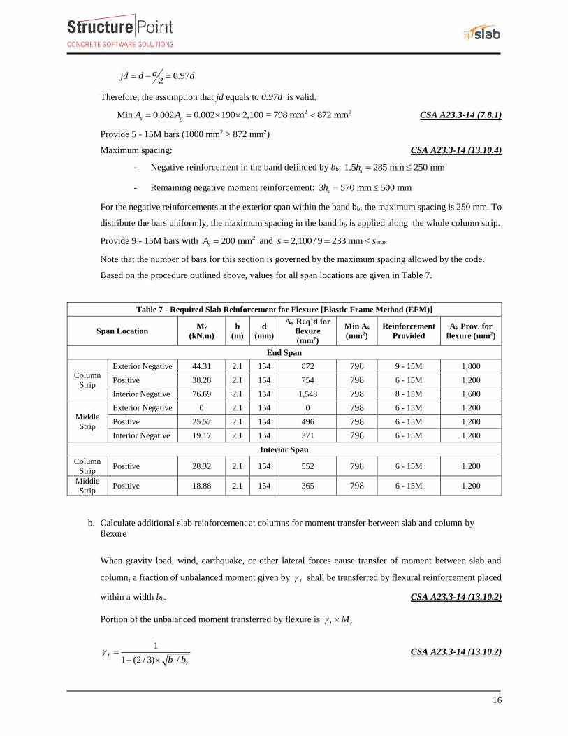
Based on the procedure outlined above, values for all span locations are given in Table 7.
Table 7 - Required Slab Reinforcement for Flexure [Elastic Frame Method (EFM)]
Span Location Mr
(kN.m)
b
(m)
d
(mm)
As Req’d for
flexure
(mm2)
Min As
(mm2)
Reinforcement
Provided
As Prov. for
flexure (mm2)
End Span
Column
Strip
Exterior Negative 44.31 2.1 154 872 798 9 - 15M 1,800
Positive 38.28 2.1 154 754 798 6 - 15M 1,200
Interior Negative 76.69 2.1 154 1,548 798 8 - 15M 1,600
Middle
Strip
Exterior Negative 0 2.1 154 0 798 6 - 15M 1,200
Positive 25.52 2.1 154 496 798 6 - 15M 1,200
Interior Negative 19.17 2.1 154 371 798 6 - 15M 1,200
Interior Span
Column
Strip Positive 28.32 2.1 154 552 798 6 - 15M 1,200
Middle
Strip Positive 18.88 2.1 154 365 798 6 - 15M 1,200
b. Calculate additional slab reinforcement at columns for moment transfer between slab and column by
flexure
When gravity load, wind, earthquake, or other lateral forces cause transfer of moment between slab and
column, a fraction of unbalanced moment given by f shall be transferred by flexural reinforcement placed
within a width bb. CSA A23.3-14 (13.10.2)
Portion of the unbalanced moment transferred by flexure is f rM
1 2
1
1 (2 / 3) /f
b b
CSA A23.3-14 (13.10.2)
17
Where
b1 = Width width of the critical section for shear measured in the direction of the span for which moments
are determined according to CSA A23.3-14, clause 13 (see Figure 5).
b2 = Width of the critical section for shear measured in the direction perpendicular to b1 according to CSA
A23.3-14, clause 13 (see Figure 5).
bb = Effective slab width =2 3 sc h CSA A23.3-14 (3.2)
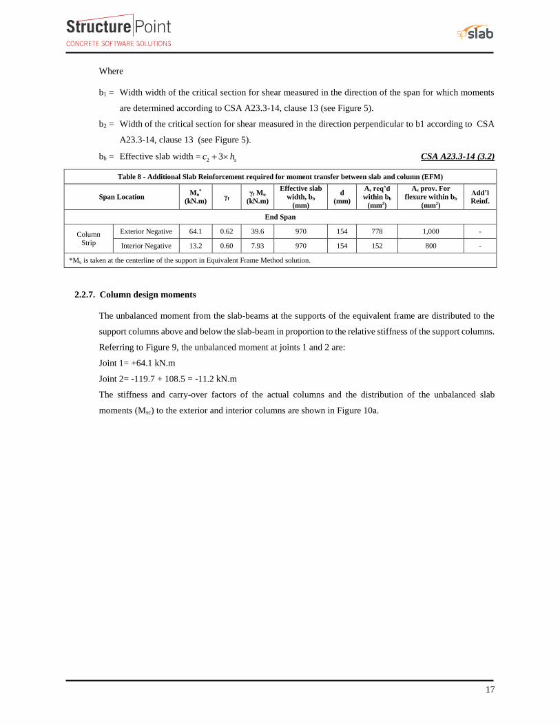
Table 8 - Additional Slab Reinforcement required for moment transfer between slab and column (EFM)
Span Location Mu
*
(kN.m) γf
γf Mu
(kN.m)
Effective slab
width, bb
(mm)
d
(mm)
As req’d
within bb
(mm2)
As prov. For
flexure within bb
(mm2)
Add’l
Reinf.
End Span
Column
Strip
Exterior Negative 64.1 0.62 39.6 970 154 778 1,000 -
Interior Negative 13.2 0.60 7.93 970 154 152 800 -
*Mu is taken at the centerline of the support in Equivalent Frame Method solution.
2.2.7. Column design moments
The unbalanced moment from the slab-beams at the supports of the equivalent frame are distributed to the
support columns above and below the slab-beam in proportion to the relative stiffness of the support columns.
Referring to Figure 9, the unbalanced moment at joints 1 and 2 are:
Joint 1= +64.1 kN.m
Joint 2= -119.7 + 108.5 = -11.2 kN.m
The stiffness and carry-over factors of the actual columns and the distribution of the unbalanced slab
moments (Msc) to the exterior and interior columns are shown in Figure 10a.

18
Figure 10a - Column Moments (Unbalanced Moments from Slab-Beam)
In summary:
, 30.33 kN.mcol ExteriorM
, 5.3 kN.mcol InteriorM
The moments determined above are combined with the factored axial loads (for each story) and factored
moments in the transverse direction for design of column sections. Figure 10b shows the moment diagrams
in the longitudinal and transverse direction for the interior and exterior equivalent frames. Following the
previous procedure, the moment values at the face of interior, exterior, and corner columns from the
unbalanced moment values can be obtained. These values are shown in the following table.

19
Figure 10b – Moment Diagrams (kips-ft)
Mu
kN.m
Column number (See Figure 10b)
1 2 3 4
Mux 5.24 30.56 2.93 17.2
Muy 3.22 1.79 18.47 10.34
3. Design of Interior, Edge, and Corner Columns
This section includes the design of interior, edge, and corner columns using spColumn software. The preliminary
dimensions for these columns were calculated previously in section one. The reduction of live load will be
ignored in this example. However, the detailed procedure to calculate the reduced live loads is explained in the
“wide-Module Joist System” example.

20
3.1. Determination of factored loads
Interior Column (Column #1):
Assume 4 story building
Tributary area for interior column is 2(5.5 4.2) 23.1 TributaryA m
4 4 9.8 23.1 226.38 kNu f TributaryP w A
Mu,x = 5.24 kN.m (see the previous Table)
Mu,y = 3.22 kN.m (see the previous Table)
Edge (Exterior) Column (Column #2):
Tributary area for interior column is 2(5.5 / 2 14) 11.55 mTributaryA
4 4 9.8 11.5 113.19 kNu u TributaryP q A
Mu,x = 30.56 kN.m (see the previous Table)
Mu,y = 1.79 kN.m (see the previous Table)
Edge (Exterior) Column (Column #3):
Tributary area for interior column is 2(5.5 4.2 / 2) 11.5 mTributaryA
4 4 9.8 1155 113.19 kNu u TributaryP q A
Mu,x = 2.93 kN.m (see the previous Table)
Mu,y = 18.47 kN.m (see the previous Table)
Corner Column (Column #4):
Tributary area for interior column is 2(5.5 / 2 4.2 / 2) 5.78 mTributaryA
4 4 9.8 5.78 56.6 kNu u TributaryP q A
Mu,x = 17.2 kN.m (see the previous Table)
Mu,y = 10.34 kN.m (see the previous Table)
The factored loads are then input into spColumn to construct the axial load – moment interaction diagram.

21
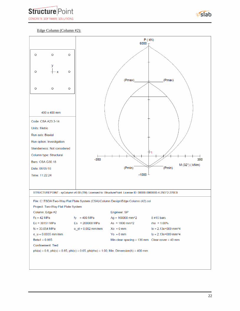
3.2. Column Capacity Diagram (Axial-Moment Interaction Diagram)
Interior Column (Column #1):
22
Edge Column (Column #2):

23
Edge Column (Column #3):

24
Corner Column (Column #4):
25
4. Two-Way Slab Shear Strength
Shear strength of the slab in the vicinity of columns/supports includes an evaluation of one-way shear (beam
action) and two-way shear (punching) in accordance with CSA A23.3-14 clause 13.
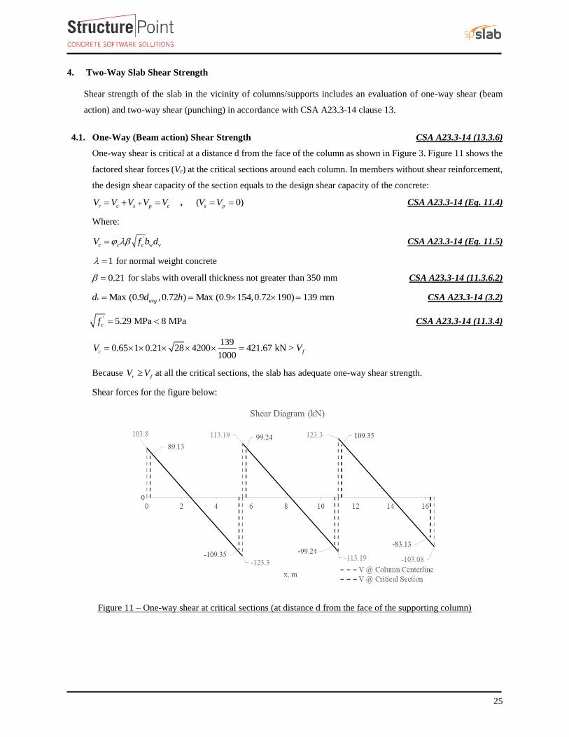
4.1. One-Way (Beam action) Shear Strength CSA A23.3-14 (13.3.6)
One-way shear is critical at a distance d from the face of the column as shown in Figure 3. Figure 11 shows the
factored shear forces (Vr) at the critical sections around each column. In members without shear reinforcement,
the design shear capacity of the section equals to the design shear capacity of the concrete:
r c s p cV V V V V , ( 0)s pV V CSA A23.3-14 (Eq. 11.4)
Where:
'
c c c w vV f b d CSA A23.3-14 (Eq. 11.5)
1 for normal weight concrete
0.21 for slabs with overall thickness not greater than 350 mm CSA A23.3-14 (11.3.6.2)
Max (0.9 ,0.72 ) Max (0.9 154,0.72 190) 139 mmv avgd d h CSA A23.3-14 (3.2)
' 5.29 MPa 8 MPacf CSA A23.3-14 (11.3.4)
1390.65 1 0.21 28 4200 421.67 kN >
1000c fV V
Because r fV V at all the critical sections, the slab has adequate one-way shear strength.
Shear forces for the figure below:
Figure 11 – One-way shear at critical sections (at distance d from the face of the supporting column)

26
4.2. Two-Way (Punching) Shear Strength CSA A23.3-14 (13.3.2)
Two-way shear is critical on a rectangular section located at d/2 away from the face of the column as shown in
Figure 5.
a. Exterior column:
The factored shear force (Vf) in the critical section is computed as the reaction at the centroid of the critical
section minus the self-weight and any superimposed surface dead and live load acting within the critical section
(d/2 away from column face).
103.8 9.8 0.477 0.554 101.21kNfV
The factored unbalanced moment used for shear transfer, Munb, is computed as the sum of the joint moments to
the left and right. Moment of the vertical reaction with respect to the centroid of the critical section is also taken
into account.
unb
477 150.9 400 / 2M 64.1 101.21 51.34 kN.m
1000
For the exterior column in Figure 5, the location of the centroidal axis z-z is:
AB
moment of area of the sides about AB 2 (447 154 447 / 2)c 150.9 mm
area of the sides 2 447 154 554 154e
The polar moment Jc of the shear perimeter is:
23 3
21 1 11 2J 2
12 12 2c AB AB
b d db bb d c b dc
23 3
2 9 4477 154 154 477 477J 2 477 154 150.9 554 154 (150.9) 6.15 10 mm
12 12 2c
1 1 0.618 0.382v f CSA A23.3-14 (Eq. 13.8)
The length of the critical perimeter for the exterior column:
ob 2 (400 154 / 2) (400 154) 1508mm
The two-way shear stress (vu) can then be calculated as:
f v unbf
o
V M ev
b d J
CSA A23.3-14 (Eq.13.9)
6
9
101.21 1000 0.382 (51.34 10 ) 150.90.92 MPa
1508 154 6.15 10fv
The factored resisiting shear stress, Vr shall be the smallest of : CSA A23.3-14 (13.3.4.1)

27
a) '2 21 0.19 1 0.19 0.65 28 1.96 MPa
1r c c c
c
v v f
b) ' 3 1540.19 0.19 1 0.65 28 1.71 MPa
1508
s
r c c c
o
dv v f
b
c) '0.38 0.38 1 0.65 28 1.31 MPar c c cv v f
Since frv v at the critical section, the slab has adequate two-way shear strength at this joint.
b. Interior column:
6
554 554113.19 123.3 9.8 233.48 kN
10fV
119.7 108.5 233.48(0) 11.2 kN.munbM
For the interior column in Figure 5, the location of the centroidal axis z-z is:
1 554277 mm
2 2AB
bc
The polar moment Jc of the shear perimeter is:
23 3
21 1 11 22
12 12 2c AB AB
b d db bJ b d c b dc
23 3
2 10 4554 154 154 554 554J 2 554 154 277 2 554 154 (277) 1.78 10 mm
12 12 2c
1 1 0.60 0.40v f CSA A23.3-14 (Eq. 13.8)
The length of the critical perimeter for the interior column:
ob 2 (400 154) 2 (400 154) 2216 mm
f v unbf
o
V M ev
b d J
CSA A23.3-14 (Eq.13.9)
6
10
233.48 1000 0.4 (11.2 10 ) 2770.75 MPa
2216 154 1.78 10fv
The factored resisiting shear stress, Vr shall be the smallest of : CSA A23.3-14 (13.3.4.1)
a) '2 21 0.19 1 0.19 0.65 28 1.96 MPa
1r c c c
c
v v f
28
b) ' 4 1540.19 0.19 1 0.65 28 1.61 MPa
2216
s
r c c c
o
dv v f
b
c) '0.38 0.38 1 0.65 28 1.31 MPar c c cv v f
Since frv v at the critical section, the slab has adequate two-way shear strength at this joint.
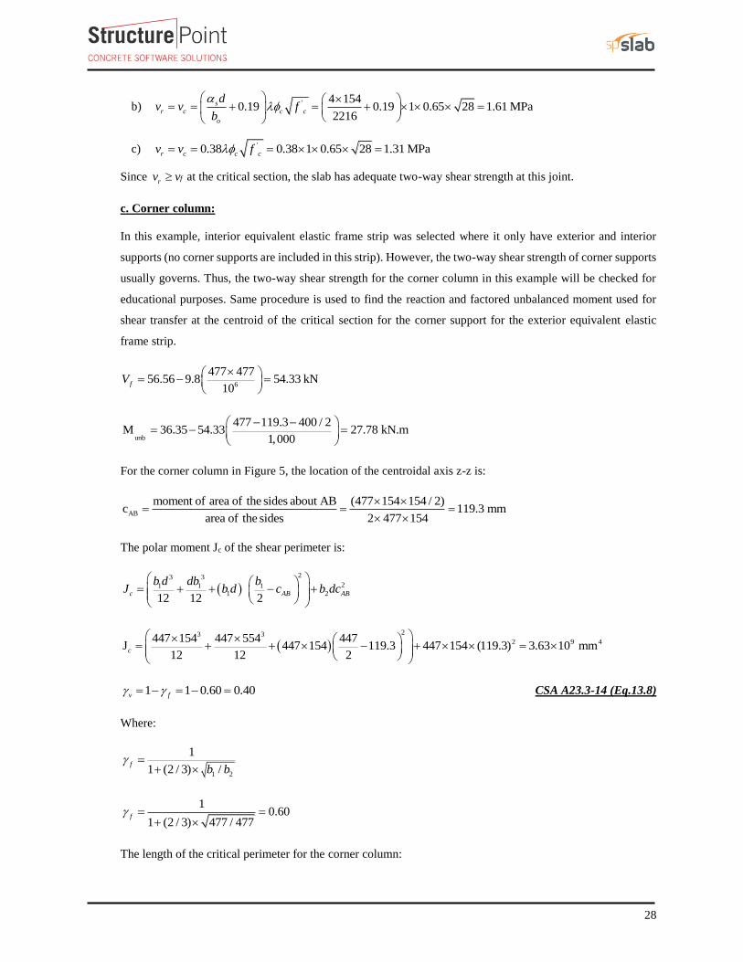
c. Corner column:
In this example, interior equivalent elastic frame strip was selected where it only have exterior and interior
supports (no corner supports are included in this strip). However, the two-way shear strength of corner supports
usually governs. Thus, the two-way shear strength for the corner column in this example will be checked for
educational purposes. Same procedure is used to find the reaction and factored unbalanced moment used for
shear transfer at the centroid of the critical section for the corner support for the exterior equivalent elastic
frame strip.
6
477 47756.56 9.8 54.33 kN
10fV
unb
477 119.3 400 / 2M 36.35 54.33 27.78 kN.m
1,000
For the corner column in Figure 5, the location of the centroidal axis z-z is:
AB
moment of area of the sides about AB (477 154 154 / 2)c 119.3 mm
area of the sides 2 477 154
The polar moment Jc of the shear perimeter is:
23 3
21 1 11 2
12 12 2c AB AB
b d db bJ b d c b dc
23 3
2 9 4447 154 447 554 447J 447 154 119.3 447 154 (119.3) 3.63 10 mm
12 12 2c
1 1 0.60 0.40v f CSA A23.3-14 (Eq.13.8)
Where:
1 2
1
1 (2 / 3) /f
b b
10.60
1 (2 / 3) 477 / 477f
The length of the critical perimeter for the corner column:

29
(400 154 / 2) (400 154 / 2) 954 mmob
The two-way shear stress (vu) can then be calculated as:
f v unbf
o
V M ev
b d J
CSA A23.3-14 (Eq.13.9)
6
9
54.33 1000 0.4 (27.78 10 ) 119.30.74 MPa
954 154 3.63 10fv
The factored resisiting shear stress, Vr shall be the smallest of : CSA A23.3-14 (13.3.4.1)
a) '2 21 0.19 1 0.19 0.65 28 1.96 MPa
1r c c c
c
v v f
b) ' 2 1540.19 0.19 1 0.65 28 1.76 MPa
954
s
r c c c
o
dv v f
b
c) '0.38 0.38 1 0.65 28 1.31 MPar c c cv v f
Since frv v at the critical section, the slab has adequate two-way shear strength at this joint.
5. Two-Way Slab Deflection Control (Serviceability Requirements)
Since the slab thickness was selected based on the minimum slab thickness equations in CSA A23.3-14, the
deflection calculations are not required. However, the calculations of immediate and time-dependent deflections
are covered in this section for illustration and comparison with spSlab model results.
5.1. Immediate (Instantaneous) Deflections
When deflections are to be computed, deflections that occur immediately on application of load shall be
computed by methods or formulas for elastic deflections, taking into consideration the effects of cracking and
reinforcement on member stiffness. Unless deflections are determined by a more comprehensive analysis,
immediate deflection shall be computed using elastic deflection equations. CSA A23.3-14 (9.8.2.2 & 9.8.2.3)
Elastic analysis for three service load levels (D, D + Lsustained, D+LFull) is used to obtain immediate deflections
of the two-way slab in this example. However, other procedures may be used if they result in predictions of
deflection in reasonable agreement with the results of comprehensive tests.
The effective moment of inertia (Ie) is used to account for the cracking effect on the flexural stiffness of the
slab. Ie for uncracked section (Mcr > Ma) is equal to Ig. When the section is cracked (Mcr < Ma), then the
following equation should be used:
3
cre cr g cr g
a
MI I I I I
M
CSA A23.3-14 (Eq.9.1)
Where:

30
Ma = Maximum moment in member due to service loads at stage deflection is calculated.
The values of the maximum moments for the three service load levels are calculated from structural analysis as
shown previously in this document. These moments are shown in Figure 12.
Figure 12 – Maximum Moments for the Three Service Load Levels
Mcr = cracking moment.
9
63.17 / 2 (2.4 10 )
10 40.11 kN.m95
r g
cr
t
f IM
Y
CSA A23.3-14 (Eq.9.2)
fr should be taken as half of Eq.8.3 CSA A23.3-14 (9.8.2.3)
fr = Modulus of rapture of concrete.
'0.6 0.6 1.0 28 3.17 MPar cf f CSA A23.3-14 (Eq.8.3)
Ig = Moment of inertia of the gross uncracked concrete section

31
33
9 424200 190
2.4 10 mm12 12
g
l hI
19095mm
2 2t
hY
Icr = moment of inertia of the cracked section transformed to concrete.
CAC Concrete Design Handbook 4th Edition (5.2.3)
The calculations shown below are for the design strip (frame strip). The values of these parameters for column
and middle strips are shown in Table 9.
As calculated previously, the exterior span frame strip near the interior support is reinforced with 14 – 15 M
bars located at 350 mm along the section from the top of the slab. Figure 13 shows all the parameters needed
to calculate the moment of inertia of the cracked section transformed to concrete.
Figure 13 – Cracked Transformed Section
Ecs = Modulus of elasticity of slab concrete.
1.5 1.5
' 2,447(3,300 6,900) (3,300 28 6,900) 26,739 MPa
2,300 2,300
c
cs cE f
CSA A23.3-14(8.6.2.2 )
200,0007.48
26,739
s
cs
En
E CAC Concrete Design Handbook 4th Edition (Table 6.2a)
14200
0.2 mm 7.48 14 200s
bB
n A
CAC Concrete Design Handbook 4th Edition (Table 6.2a)
2 1 1 2 154 0.2 1 134.52 mm
0.2
dBkd
B
CAC Concrete Design Handbook 4th Edition (Table 6.2a)
32( )
( )3
cr s
b kdI nA d kd CAC Concrete Design Handbook 4th Edition (Table 6.2a)
3
2 8 44,200 (34.52)7.48 14 200 154 34.52 3.57 10 mm
3crI
The effective moment of inertia procedure is considered sufficiently accurate to estimate deflections. The
effective moment of inertia, Ie, was developed to provide a transition between the upper and lower bounds of
Ig and Icr as a function of the ratio Mcr/Ma. For conventionally reinforced (nonprestressed) members, the
effective moment of inertia, Ie, shall be calculated by Eq. (9.1) in CSA A23.3-14 unless obtained by a more
comprehensive analysis.
32
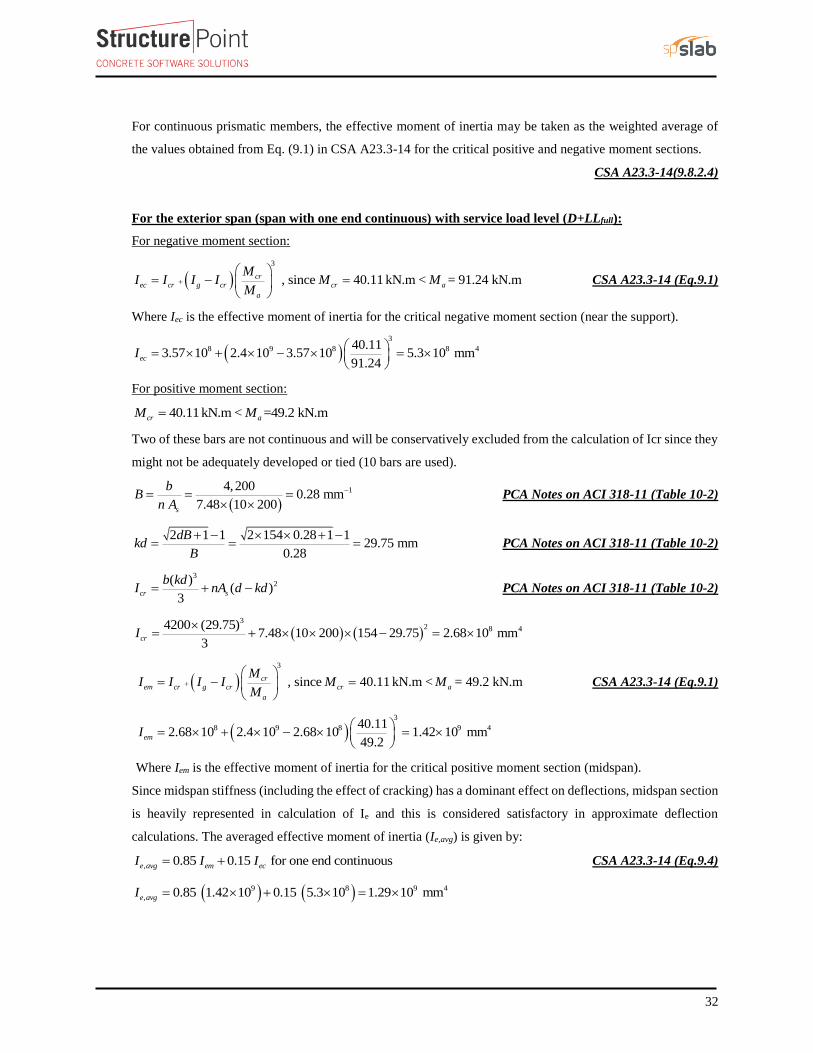
For continuous prismatic members, the effective moment of inertia may be taken as the weighted average of
the values obtained from Eq. (9.1) in CSA A23.3-14 for the critical positive and negative moment sections.
CSA A23.3-14(9.8.2.4)
For the exterior span (span with one end continuous) with service load level (D+LLfull):
For negative moment section:
3
, since 40.11 kN.m < = 91.24 kN.mcrec cr g cr cr a
a
MI I I I M M
M
CSA A23.3-14 (Eq.9.1)
Where Iec is the effective moment of inertia for the critical negative moment section (near the support).
3
8 9 8 8 440.113.57 10 2.4 10 3.57 10 5.3 10 mm
91.24ecI
For positive moment section:
40.11kN.m < =49.2 kN.mcr aM M
Two of these bars are not continuous and will be conservatively excluded from the calculation of Icr since they
might not be adequately developed or tied (10 bars are used).
14,200
0.28 mm 7.48 10 200s
bB
n A
PCA Notes on ACI 318-11 (Table 10-2)
2 1 1 2 154 0.28 1 129.75 mm
0.28
dBkd
B
PCA Notes on ACI 318-11 (Table 10-2)
32( )
( )3
cr s
b kdI nA d kd PCA Notes on ACI 318-11 (Table 10-2)
3
2 8 44200 (29.75)7.48 10 200 154 29.75 2.68 10 mm
3crI
3
, since 40.11 kN.m < = 49.2 kN.mcrem cr g cr cr a
a
MI I I I M M
M
CSA A23.3-14 (Eq.9.1)
3
8 9 8 9 440.112.68 10 2.4 10 2.68 10 1.42 10 mm
49.2emI
Where Iem is the effective moment of inertia for the critical positive moment section (midspan).
Since midspan stiffness (including the effect of cracking) has a dominant effect on deflections, midspan section
is heavily represented in calculation of Ie and this is considered satisfactory in approximate deflection
calculations. The averaged effective moment of inertia (Ie,avg) is given by:
, 0.85 0.15 for one end continuouse avg em ecI I I CSA A23.3-14 (Eq.9.4)
9 8 9 4
, 0.85 1.42 10 0.15 5.3 10 1.29 10 mme avgI

33
For the interior span (span with both ends continuous) with service load level (D+LLfull):
3
, since 41.11 kN.m < = 82.8 kN.mcrec cr g cr cr a
a
MI I I I M M
M
CSA A23.3-14 (Eq.9.1)
3
8 9 8 8 440.113.57 10 2.4 10 3.57 10 5.89 10 mm
82.8ecI
9 42.4 10 mm , since 40.11kN.m > = 35.67 kN.mem g cr aI I M M
The averaged effective moment of inertia (Ie,avg) is given by:
, 1 20.70 0.15 for two ends continuouse avg em e eI I I I CSA A23.3-14 (Eq.9.3)
9 8 8 9 4
, 0.70 2.4 10 0.15 5.89 10 5.89 10 1.86 10 mme avgI
Where:
1 = The effective moment of inertia for the critical negative moment section at end 1 of continuous beam span.eI
2 = The effective moment of inertia for the critical negative moment section at end 2 of continuous beam span.eI
Table 9 provides a summary of the required parameters and calculated values needed for deflections for exterior
and interior equivalent elastic frame. It also provides a summary of the same values for column strip and middle
strip to facilitate calculation of panel deflection.

34
Table 9 – Averaged Effective Moment of Inertia Calculations
For Frame Strip
Span zone Ig,
mm4
(×108)
Icr,
mm4
(×108)
Ma, kN.m Mcr,
kN.m
Ie, mm4 (×108) Ie,avg, mm4 (×108)
D D +
LLSus
D +
Lfull D
D +
LLSus
D +
Lfull D
D +
LLSus
D +
Lfull
Ext
Left
24
3.78 -36.64 -36.64 -49.17
40.11
24 24 14.5
21.6 21.6 12.9 Midspan 2.68 36.67 36.67 49.2 24 24 14.4
Right 3.57 -68.00 -68.00 -91.24 7.76 7.76 5.3
Int
Left 3.57 -61.71 -61.71 -82.80 9.18 9.18 5.89
19.6 19.6 18.6 Mid 2.68 26.58 26.58 35.67 24 24 24
Right 3.57 -61.71 -61.71 -82.80 9.18 9.18 5.89
Deflections in two-way slab systems shall be calculated taking into account size and shape of the panel,
conditions of support, and nature of restraints at the panel edges. For immediate deflections two-way slab
systems the midpanel deflection is computed as the sum of deflection at midspan of the column strip or column
line in one direction (Δcx or Δcy) and deflection at midspan of the middle strip in the orthogonal direction (Δmx
or Δmy). Figure 14 shows the deflection computation for a rectangular panel. The average Δ for panels that have
different properties in the two direction is calculated as follows:
2
cx my cy mx PCA Notes on ACI 318-11 (9.5.3.4 Eq. 8)
Figure 14 – Deflection Computation for a rectangular Panel
To calculate each term of the previous equation, the following procedure should be used. Figure 15 shows the
procedure of calculating the term Δcx. same procedure can be used to find the other terms.

35
Figure 15 –Δcx calculation procedure
For exterior span - service dead load case:
4
,
,384frame fixed
c frame averaged
wl
E I PCA Notes on ACI 318-11 (9.5.3.4 Eq. 10)
Where:
, = Deflection of column strip assuing fixed end condition.frame fixed
(1 24 .19)(4.2) 23.35 kN/mw
1.5
'(3,300 6,900)2,300
c
c cE f
CSA A23.3-14(8.6.2.2)
1.5
2,447(3,300 28 6,900) 26,739 MPa
2,300cE
Iframe,averaged = The averaged effective moment of inertia (Ie,avg) for the frame strip for service dead load case
from Table 9 = 21.6×10⁸
43
, 8
(23.35)(5,500)10 0.96 mm
384(26,739)(21.6 10 )frame fixed
, ,
frame
c fixed c frame fixed
c
ILDF
I PCA Notes on ACI 318-11 (9.5.3.4 Eq. 11)
Where LDFc is the load distribution factor for the column strip. The load distribution factor for the column strip
can be found from the following equation:

36
2
2
l R
c
LDF LDFLDF
LDF
And the load distribution factor for the middle strip can be found from the following equation:
1m cLDF LDF
For the end span, LDF for exterior negative region (LDFL¯), interior negative region (LDFR¯), and positive
region (LDFL+
) are 1.00, 0.75, and 0.60, respectively (From Table 6 of this document). Thus, the load
distribution factor for the column strip for the end span is given by:
1.0 0.80.6
2 0.752
cLDF
Ic,g = The gross moment of inertia (Ig) for the column strip for service dead load = 1.2×109 mm4
9
, 9
2.4 100.75 0.96 1.45 mm
1.2 10c fixed
,
,
( )net L frame
c L
ec
M
K PCA Notes on ACI 318-11 (9.5.3.4 Eq. 12)
Where:
, = Rotation of the span left support.c L
,( ) 36.64 kN.m = Net frame strip negative moment of the left support.net L frameM
Kec = effective column stiffness = 6.91×10⁶ N.m (calculated previously).
3
, 6
36.64 100.00053 rad
69.1 10c L
, , 8
g
c L c L
e frame
Il
I
PCA Notes on ACI 318-11 (9.5.3.4 Eq. 14)
Where:
, = Midspan deflection due to rotation of left support.c L
= Gross-to-effective moment of inertia ratio for frame strip.g
e frame
I
I
9
, 9
5,500 2.4 100.00053 0.41 mm
8 2.16 10c L
3,
, 6
(68 61.71) 100.000091 rad
69.1 10
net R frame
c R
ec
M
K
Where

37
,c R = rotation of the span right support.
,net R frameM
= Net frame strip negative moment of the right support.
9
, , 9
5,500 2.4 100.000091 0.07 mm
8 2.1 108
g
c R c R
e frame
Il
I
Where:
, = Midspan deflection due to rotation of right support.c R
, , ,cx cx fixed cx R cx L PCA Notes on ACI 318-11 (9.5.3.4 Eq. 9)
1.45 0.07 0.41 1.92 mmcx
Following the same procedure, Δmx can be calculated for the middle strip. This procedure is repeated for the
equivalent frame in the orthogonal direction to obtain Δcy, and Δmy for the end and middle spans for the other
load levels (D+LLsus and D+LLfull).
Assuming square panel, Δcx = Δcy= 1.92 mm. and Δmx = Δmy= 0.96 mm
The average Δ for the corner panel is calculated as follows:
( ) ( )
1.92 0.96 2.88 mm2
cx my cy mx
cx my cy mx

38
Table 10 – Immediate (Instantaneous) Deflections in the x-direction
Column Strip
Middle Strip
Span LDF
D
LDF
D
Δframe-fixed,
mm
Δc-fixed,
mm
θc1,
rad
θc2,
rad
Δθc1,
mm
Δθc2,
mm
Δcx,
mm
Δframe-fixed,
mm
Δm-fixed,
mm
θm1,
rad
θm2,
rad
Δθm1,
mm
Δθm2,
mm
Δmx,
mm
Ext 0.75 0.96 1.45 0.00053 0.000091 0.41 0.07 1.92
0.25 0.96 0.48 0.00053 0.000091 0.41 0.07 0.96
Int 0.7 1.06 1.49 -0.00091 -0.00091 -0.08 -0.08 1.33
0.30 1.06 0.64 -0.00009 -0.00009 -0.08 -0.08 0.48
Span LDF
D+LLsus
LDF
D+LLsus
Δframe-fixed,
mm
Δc-fixed,
mm
θc1,
rad
θc2,
rad
Δθc1,
mm
Δθc2,
mm
Δcx,
mm
Δframe-fixed,
mm
Δm-fixed,
mm
θm1,
rad
θm2,
rad
Δθm1,
mm
Δθm2,
mm
Δmx,
mm
Ext 0.75 0.96 1.45 0.00053 0.000091 0.41 0.07 1.92
0.25 0.96 0.48 0.00053 0.000091 0.41 0.07 0.96
Int 0.7 1.06 1.49 -0.00091 -0.00091 -0.08 -0.08 1.33
0.30 1.06 0.64 -0.00009 -0.00009 -0.08 -0.08 0.48
Span LDF
D+LLfull
LDF
D+LLfull
Δframe-fixed,
mm
Δc-fixed,
mm
θc1,
rad
θc2,
rad
Δθc1,
mm
Δθc2,
mm
Δcx,
mm
Δframe-fixed,
mm
Δm-fixed,
mm
θm1,
rad
θm2,
rad
Δθm1,
mm
Δθm2,
mm
Δmx,
mm
Ext 0.75 2.16 3.25 0.00071 0.00012 0.91 0.16 4.31
0.25 2.16 1.08 0.00071 0.00012 0.91 0.16 2.15
Int 0.7 1.50 2.1 -0.00012 -0.00012 -0.11 -0.11 1.88
0.30 1.50 0.9 -0.00012 -0.00012 -0.11 -0.11 0.68
Span LDF
LL
LDF
LL
Δcx,
mm Δmx,
mm Ext 0.75 2.39
0.25 1.19
Int 0.7 0.55
0.30 0.2

39
From the analysis in the transverse direction the deflection values below are obtained:
For DL loading case:
my
cy
For DL+LLsust loading case:
my
cy
For DL+LLfull loading case:
my
cy
These values for the x-direction are shown in Table 10. Then, the total midpanel deflection is calculated by
combining the contributions of the column and middle strip deflections from the X and Y directions:
2
cx my cy mx PCA Notes on ACI 318-11 (9.5.3.4 Eq. 8)
5.2. Time-Dependent (Long-Term) Deflections (Δlt) (CSA)
The additional time-dependent (long-term) deflection resulting from creep and shrinkage (Δcs) may be estimated
as follows:
( ) cs sust Inst PCA Notes on ACI 318-11 (9.5.2.5 Eq. 4)
The total immediate and long-term deflection is calculated as:
( ) ( ) (1 ) [( ) ( ) ]sust Inst total Inst sust Insttotal lt CSA A23.3-04 (N9.8.2.5)
Where:
( ) Immediate (instantaneous) deflection due to sustained loadsust Inst
Unless values are obtained by a more comprehensive analysis, the total immediate plus long-term deflection
for flexural members shall be obtained by multiplying the immediate deflection caused by the sustained load
considered by the factor ζs, as follows: CSA23.3-14 (9.8.2.5)
11 50 '
s
s
CSA23.3-14 (Eq .9.5)
For the exterior span
s = 2, consider the sustained load duration to be 60 months or more. CSA A23.3-14 (9.8.2.5)
' = 0, conservatively.

40
22
1 50 ' 1 50 0
s
2 1.92 3.84 mmcs
1.92 1 2 4.31 1.92 8.16 mmtotal lt
Table 11 shows long-term deflections for the exterior and interior spans for the analysis in the x-direction, for
column and middle strips.
Table 11 - Long-Term Deflections
Column Strip
Span (Δsust)Inst, mm λΔ Δcs, mm (Δtotal)Inst, mm (Δtotal)lt, mm
Exterior 1.92 2.000 3.84 4.31 6.37
Interior 1.33 2.000 2.66 1.88 4.64
Middle Strip
Exterior 0.96 2.000 1.92 2.15 4.06
Interior 0.48 2.000 0.96 0.68 1.65
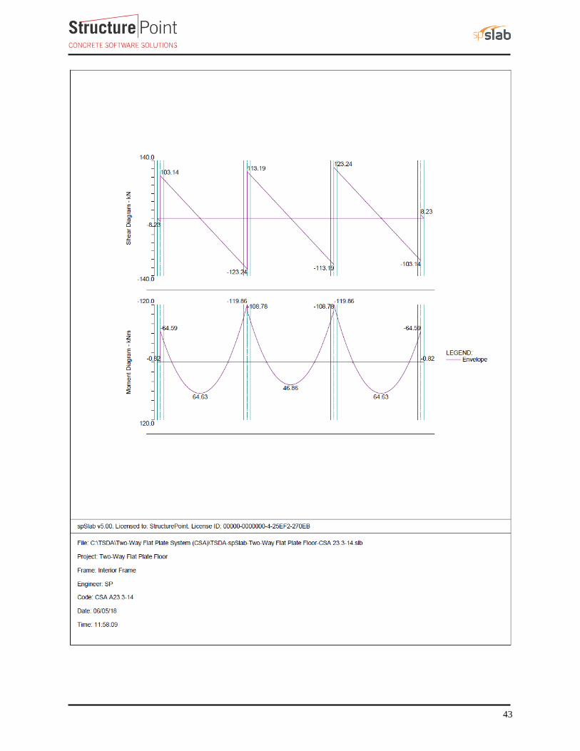
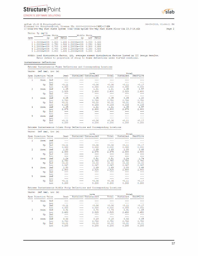
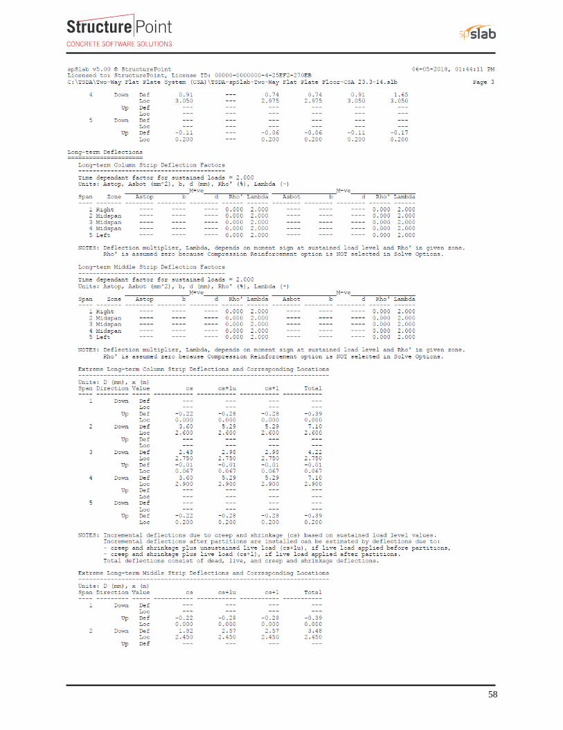
6. Computer Program Solution
spSlab program utilizes the Elastic (Equivalent) Frame Method described and illustrated in details here for
modeling, analysis and design of two-way concrete floor slab systems. spSlab uses the exact geometry and
boundary conditions provided as input to perform an elastic stiffness (matrix) analysis of the equivalent frame
taking into account the torsional stiffness of the slabs framing into the column. It also takes into account the
complications introduced by a large number of parameters such as vertical and torsional stiffness of transverse
beams, the stiffening effect of drop panels, column capitals, and effective contribution of columns above and
below the floor slab using the of equivalent column concept.
spSlab Program models the equivalent elastic frame as a design strip. The design strip is, then, separated by spSlab
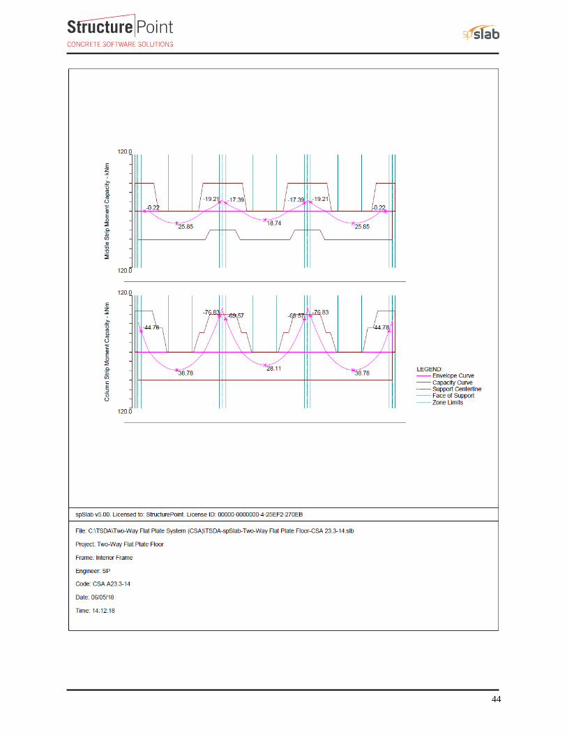
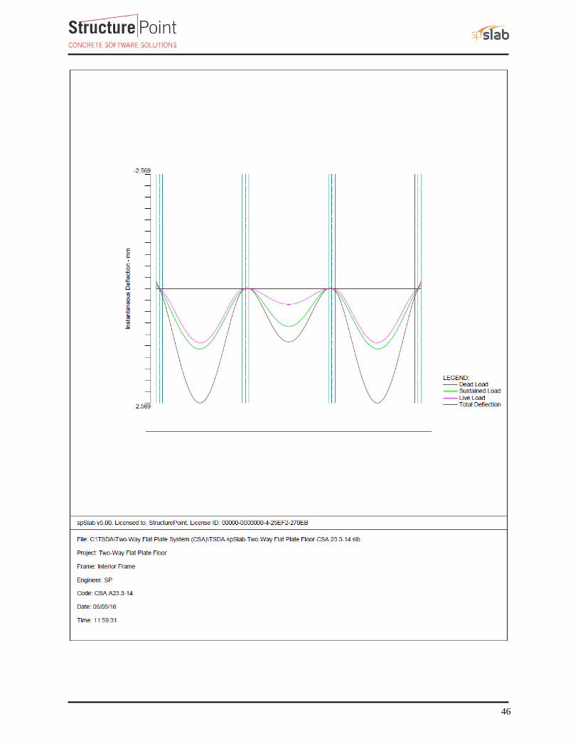
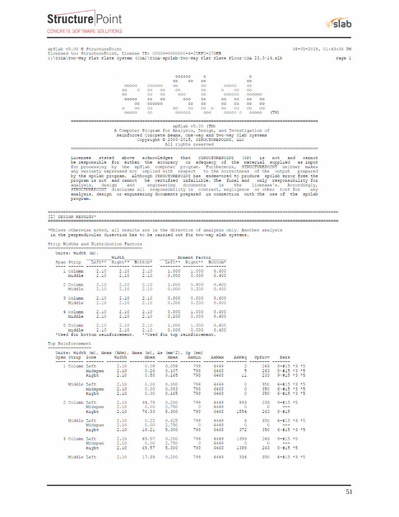
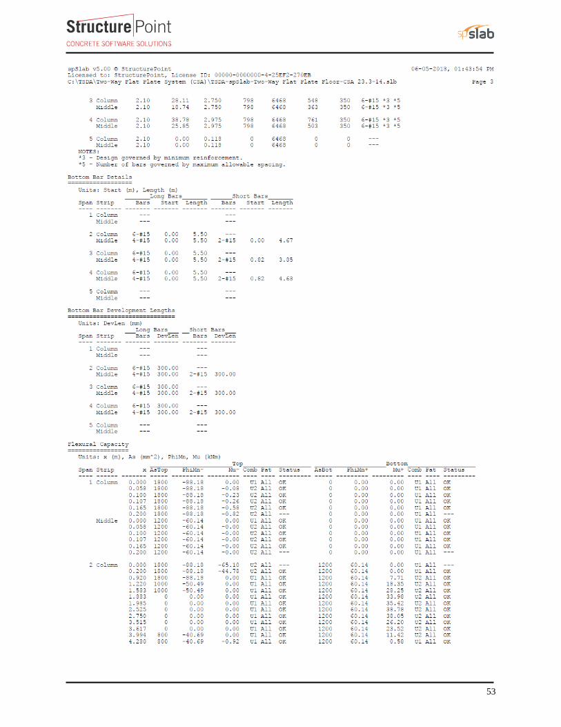
into column and middle strips. The program calculates the internal forces (Shear Force & Bending Moment),
moment and shear capacity vs. demand diagrams for column and middle strips, instantaneous and long-term
deflection results, and required flexural reinforcement for column and middle strips. The graphical and text results
are provided below for both input and output of the spSlab model.

41

42
43
44

45
46

47

48

49

50
51

52
53

54

55

56
57
58

59

60
7. Summary and Comparison of Two-Way Slab Design Results
Table 12 - Comparison of Moments obtained from Hand (EFM) and spSlab Solution
Hand (EFM) spSlab
Exterior Span
Column Strip
Exterior Negative* 44.31 44.78
Positive 38.28 38.78
Interior Negative* 76.69 76.83
Middle Strip
Exterior Negative* 0 0
Positive 25.52 25.85
Interior Negative* 19.98 19.21
Interior Span
Column Strip Interior Negative* 69.35 69.57
Positive 28.32 28.11
Middle Strip Interior Negative* 17.34 17.39
Positive 18.88 18.74
* negative moments are taken at the faces of supports
Table 13 - Comparison of Reinforcement Results with Hand and spSlab Solution
Span Location
Reinforcement Provided
for Flexure
Additional Reinforcement
Provided for Unbalanced
Moment Transfer*
Total
Reinforcement
Provided
Hand spSlab Hand spSlab Hand spSlab
Exterior Span
Column
Strip
Exterior
Negative 9-15M 9-15M --- --- 9-15M 9-15M
Positive 6-15M 6-15M n/a n/a 6-15M 6-15M
Interior
Negative 8-15M 8-15M --- --- 8-15M 8-15M
Middle
Strip
Exterior
Negative 6-15M 6-15M n/a n/a 6-15M 6-15M
Positive 6-15M 6-15M n/a n/a 6-15M 6-15M
Interior
Negative 6-15M 6-15M n/a n/a 6-15M 6-15M
Interior Span
Column
Strip Positive 6-15M 6-15M n/a n/a 6-15M 6-15M
Middle
Strip Positive 6-15M 6-15M n/a n/a 6-15M 6-15M
* In the EFM, the unbalanced moment (Msc, Munb) at the support centerline is used to determine the value of the
additional reinforcement as compared with DDM using the moments at the face of support.
61
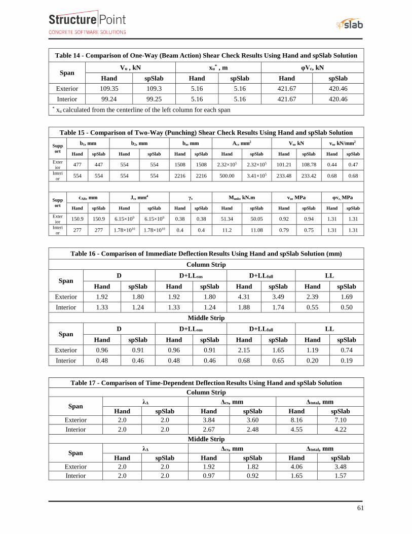
Table 14 - Comparison of One-Way (Beam Action) Shear Check Results Using Hand and spSlab Solution
Span Vu , kN xu
* , m φVc, kN
Hand spSlab Hand spSlab Hand spSlab
Exterior 109.35 109.3 5.16 5.16 421.67 420.46
Interior 99.24 99.25 5.16 5.16 421.67 420.46
* xu calculated from the centerline of the left column for each span
Table 15 - Comparison of Two-Way (Punching) Shear Check Results Using Hand and spSlab Solution
Supp
ort
b1, mm b2, mm bo, mm Ac, mm2 Vu, kN vu, kN/mm2
Hand spSlab Hand spSlab Hand spSlab Hand spSlab Hand spSlab Hand spSlab
Exter
ior 477 447 554 554 1508 1508 2.32×10⁵ 2.32×10⁵ 101.21 108.78 0.44 0.47
Interi
or 554 554 554 554 2216 2216 500.00 3.41×10⁵ 233.48 233.42 0.68 0.68
Supp
ort
cAB, mm Jc, mm4 γv Munb, kN.m vu, MPa φvc, MPa
Hand spSlab Hand spSlab Hand spSlab Hand spSlab Hand spSlab Hand spSlab
Exter
ior 150.9 150.9 6.15×10⁹ 6.15×10⁹ 0.38 0.38 51.34 50.05 0.92 0.94 1.31 1.31
Interi
or 277 277 1.78×10¹⁰ 1.78×10¹⁰ 0.4 0.4 11.2 11.08 0.79 0.75 1.31 1.31
Table 16 - Comparison of Immediate Deflection Results Using Hand and spSlab Solution (mm)
Column Strip
Span D D+LLsus D+LLfull LL
Hand spSlab Hand spSlab Hand spSlab Hand spSlab
Exterior 1.92 1.80 1.92 1.80 4.31 3.49 2.39 1.69
Interior 1.33 1.24 1.33 1.24 1.88 1.74 0.55 0.50
Middle Strip
Span D D+LLsus D+LLfull LL
Hand spSlab Hand spSlab Hand spSlab Hand spSlab
Exterior 0.96 0.91 0.96 0.91 2.15 1.65 1.19 0.74
Interior 0.48 0.46 0.48 0.46 0.68 0.65 0.20 0.19
Table 17 - Comparison of Time-Dependent Deflection Results Using Hand and spSlab Solution
Column Strip
Span λΔ Δcs, mm Δtotal, mm
Hand spSlab Hand spSlab Hand spSlab
Exterior 2.0 2.0 3.84 3.60 8.16 7.10
Interior 2.0 2.0 2.67 2.48 4.55 4.22
Middle Strip
Span λΔ Δcs, mm Δtotal, mm
Hand spSlab Hand spSlab Hand spSlab
Exterior 2.0 2.0 1.92 1.82 4.06 3.48
Interior 2.0 2.0 0.97 0.92 1.65 1.57

62
In all of the hand calculations illustrated above, the results are in close or exact agreement with the automated
analysis and design results obtained from the spSlab model except for the deflection were results are differs
slightly (See Section 8 for explanation). Excerpts of spSlab graphical and text output are given above for
illustration.
8. Deflection Calculation Methods
Deflections calculations in reinforced concrete structures can be very tedious and time consuming because of the
difficulty of accounting for the actual end boundary conditions in a building frame. As a result, numerous methods
to estimate the deflection and the member stiffness have been presented in literature. It is important to note that
these methods can only estimate deflections within an accuracy range of 20% to 40%. It is important for the
designer to be aware of this broad range of accuracy, especially in the modeling, design, and detailing of
deflection-sensitive members.
spSlab uses elastic analysis (stiffness method) to obtain deflections along the column and middle strips by
discretizing the span into 110 elements. It also takes into account the adjacent spans effects, shape effects,
supporting members stiffnesses above and below the beam, and cracked section effects based on the applied
forces. This level of detail provides the maximum accuracy possible compared with other approximate methods
used to calculate deflections. In tables 16 and 17, the deflection values calculated by spSlab is lower than the
values calculated by the approximate method recommended by PCA Notes (the method used in the hand solution).
This can be expected since the approximate method has a built-in conservatism to accommodate a wide range of
applications and conditions. The designer can use spSlab and exploit its numerous features to get a closer
deflection estimate and optimize the depth of the slab under consideration.
9. Comparison of Two-Way Slab Analysis and Design Methods
A slab system can be analyzed and designed by any procedure satisfying equilibrium and geometric compatibility.
Three established methods are widely used. The requirements for two of them are described in detail in CSA
A23.3-14 Clasues (13.8 and 13.9) for regular two-way slab systems. CSA A23.3-14 (13.5.1)
Direct Design Method (DDM) is an approximate method and is applicable to flat plate concrete floor systems that
meet the stringent requirements of CSA A23.3-14 (13.9.1). In many projects, however, these requirements limit
the usability of the Direct Design Method significantly.
The Elastic Frame Method (EFM) has less stringent limitations compared to DDM. It requires more accurate
analysis methods that, depending on the size and geometry can prove to be long, tedious, and time-consuming.
StucturePoint’s spSlab software program solution utilizes the EFM to automate the process providing
considerable time-savings in the analysis and design of two-way slab systems as compared to hand solutions using
DDM or EFM.

63
Finite Element Method (FEM) is another method for analyzing reinforced concrete slabs, particularly useful for
irregular slab systems with variable thicknesses, openings, and other features not permissible in DDM or EFM.
Many reputable commercial FEM analysis software packages are available on the market today such as spMats.
Using FEM requires critical understanding of the relationship between the actual behavior of the structure and
the numerical simulation since this method is an approximate numerical method. The method is based on several
assumptions and the operator has a great deal of decisions to make while setting up the model and applying loads
and boundary conditions. The results obtained from FEM models should be verified to confirm their suitability
for design and detailing of concrete structures.
The following table shows a general comparison between the DDM, EFM and FEM. This table covers general
limitations, drawbacks, advantages, and cost-time efficiency of each method where it helps the engineer in
deciding which method to use based on the project complexity, schedule, and budget.
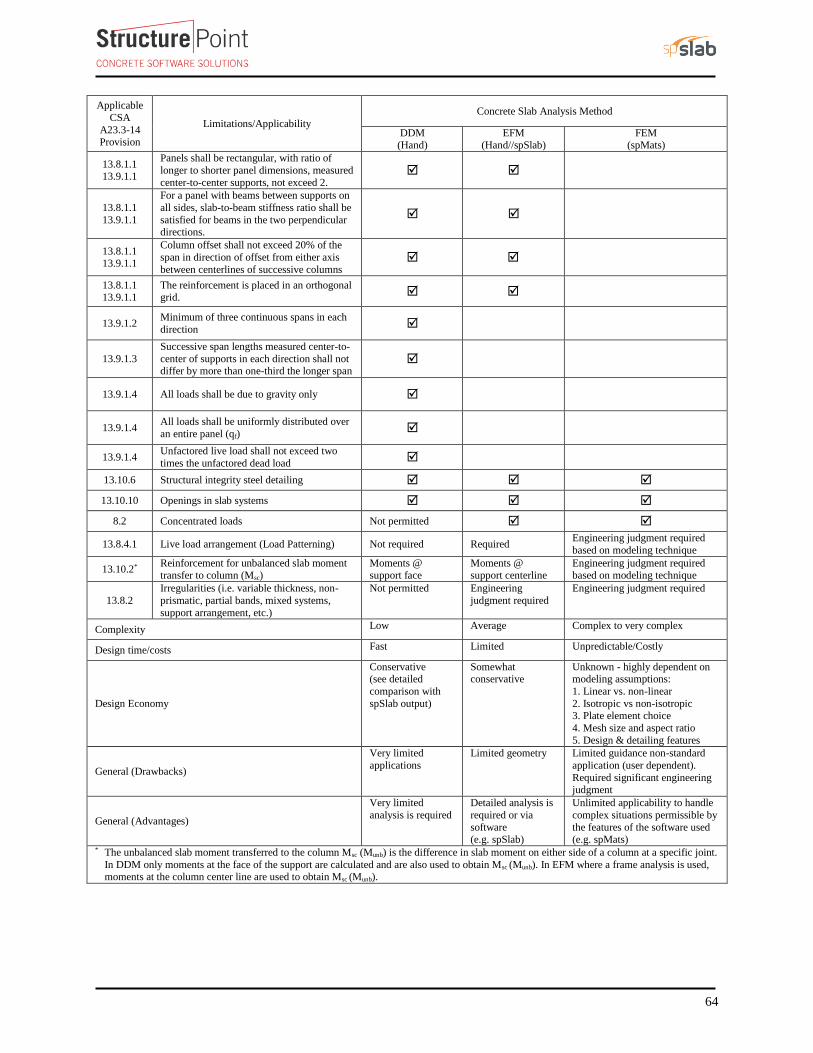
64
Applicable
CSA
A23.3-14 Provision
Limitations/Applicability
Concrete Slab Analysis Method
DDM (Hand)
EFM (Hand//spSlab)
FEM (spMats)
13.8.1.1 13.9.1.1
Panels shall be rectangular, with ratio of
longer to shorter panel dimensions, measured
center-to-center supports, not exceed 2.
13.8.1.1
13.9.1.1
For a panel with beams between supports on
all sides, slab-to-beam stiffness ratio shall be
satisfied for beams in the two perpendicular directions.
13.8.1.1 13.9.1.1
Column offset shall not exceed 20% of the
span in direction of offset from either axis
between centerlines of successive columns
13.8.1.1 13.9.1.1
The reinforcement is placed in an orthogonal grid.
13.9.1.2 Minimum of three continuous spans in each
direction
13.9.1.3
Successive span lengths measured center-to-
center of supports in each direction shall not differ by more than one-third the longer span
13.9.1.4 All loads shall be due to gravity only
13.9.1.4 All loads shall be uniformly distributed over
an entire panel (qf)
13.9.1.4 Unfactored live load shall not exceed two
times the unfactored dead load
13.10.6 Structural integrity steel detailing
13.10.10 Openings in slab systems
8.2 Concentrated loads Not permitted
13.8.4.1 Live load arrangement (Load Patterning) Not required Required Engineering judgment required
based on modeling technique
13.10.2* Reinforcement for unbalanced slab moment
transfer to column (Msc)
Moments @
support face
Moments @
support centerline
Engineering judgment required
based on modeling technique
13.8.2
Irregularities (i.e. variable thickness, non-
prismatic, partial bands, mixed systems,
support arrangement, etc.)
Not permitted Engineering
judgment required
Engineering judgment required
Complexity Low Average Complex to very complex
Design time/costs Fast Limited Unpredictable/Costly
Design Economy
Conservative (see detailed
comparison with
spSlab output)
Somewhat conservative
Unknown - highly dependent on modeling assumptions:
1. Linear vs. non-linear
2. Isotropic vs non-isotropic 3. Plate element choice
4. Mesh size and aspect ratio
5. Design & detailing features
General (Drawbacks)
Very limited
applications
Limited geometry Limited guidance non-standard
application (user dependent).
Required significant engineering judgment
General (Advantages)
Very limited
analysis is required
Detailed analysis is
required or via
software (e.g. spSlab)
Unlimited applicability to handle
complex situations permissible by
the features of the software used (e.g. spMats)
* The unbalanced slab moment transferred to the column Msc (Munb) is the difference in slab moment on either side of a column at a specific joint.
In DDM only moments at the face of the support are calculated and are also used to obtain Msc (Munb). In EFM where a frame analysis is used, moments at the column center line are used to obtain Msc (Munb).