Two Phase Heat Transfer International Topical Team … · Annual Two Phase Heat Transfer...
49
Page No. 1 NASA Physical Sciences – Presentation to Annual Two Phase Heat Transfer International Topical Team Meeting Baltimore, MD September 26, 2014 Francis Chiaramonte, Program Executive for Physical Sciences, NASA HQ Brian Motil, Deputy Branch Chief, Fluid Physics and Transport, GRC John McQuillen, Senior Aerospace Engineer, GRC https://ntrs.nasa.gov/search.jsp?R=20150004092 2018-05-31T18:25:41+00:00Z
Transcript of Two Phase Heat Transfer International Topical Team … · Annual Two Phase Heat Transfer...

Page No. 1
NASA Physical Sciences –Presentation to
Annual Two Phase Heat Transfer International Topical Team Meeting
Baltimore, MDSeptember 26, 2014
Francis Chiaramonte, Program Executive for Physical Sciences, NASA HQ
Brian Motil, Deputy Branch Chief, Fluid Physics and Transport, GRC
John McQuillen, Senior Aerospace Engineer, GRC
https://ntrs.nasa.gov/search.jsp?R=20150004092 2018-05-31T18:25:41+00:00Z

Page No. 2
SLPS Gravity-DependentPhysical Sciences Research
Fluid Physics• Adiabatic two-phase flow• Boiling, Condensation• Capillary Flow • Interfacial phenomena• Cryogenics
Complex Fluids• Colloids• Liquid crystals• Foams• Gels• Granular flows
Fundamental Physics• Space Optical/Atomic Clocks• Quantum test of Equivalence
Principle• Cold atom physics • Critical point phenomena• Dusty plasmas
Combustion Science• Spacecraft fire safety• Droplets• Gaseous – Premixed and
Non-Premixed• Solid Fuels• Supercritical reacting fluids
Biophysics• Biological macromolecules• Biomaterials• Biological physics• Fluids for Biology
Materials Science• Metals• Semiconductors• Polymers• Glasses, Ceramics• Granular Materials• Composites• Organics
Page No. 3
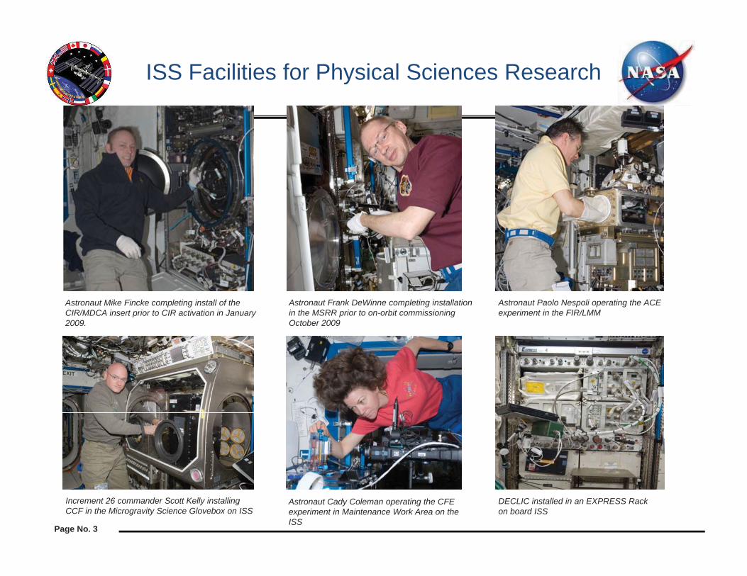
ISS Facilities for Physical Sciences Research
Astronaut Mike Fincke completing install of the CIR/MDCA insert prior to CIR activation in January 2009.
Astronaut Frank DeWinne completing installation in the MSRR prior to on-orbit commissioning October 2009
Astronaut Paolo Nespoli operating the ACE experiment in the FIR/LMM
Increment 26 commander Scott Kelly installing CCF in the Microgravity Science Glovebox on ISS
DECLIC installed in an EXPRESS Rack on board ISS
Astronaut Cady Coleman operating the CFE experiment in Maintenance Work Area on the ISS

DATA DISSEMINATIONPhysical Sciences Informatics System*
4
3. ISS flight
experimentoperations
2. NASA develops CONOPS, performs all associated science activities, and manages payload integration
1. Science Definition Team to plan and oversee scientificrequirements
CASISNon-NRAOutside Data Users
NRA to perform ground research based on data in informatics
FlightExperiments
New scientific insight and publications
5. Physical Science Informatics System
* Marshall Porterfield – based on the ISS Science Campaign White Paper 2013
4. Digital Data downlink and sample return for analysis
Flight Hardware
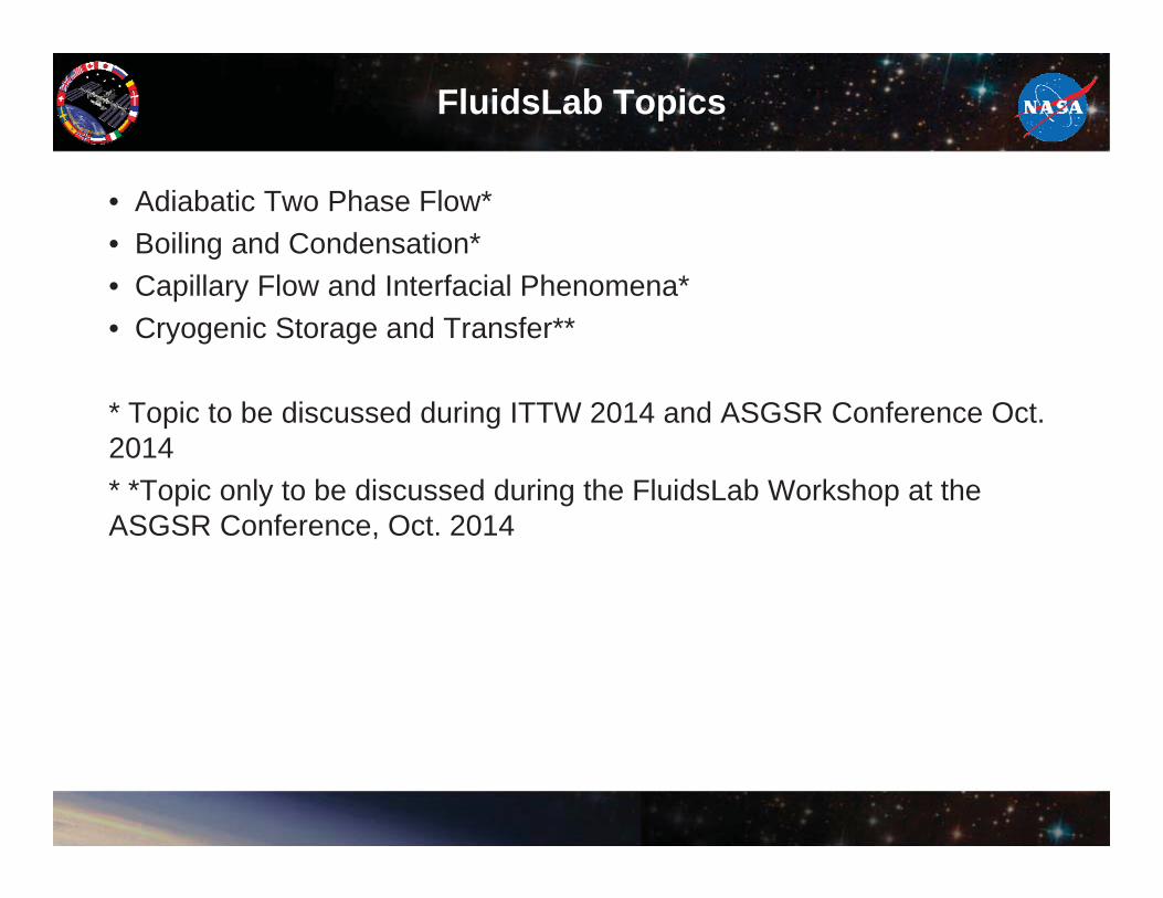
FluidsLab Topics
• Adiabatic Two Phase Flow*• Boiling and Condensation*• Capillary Flow and Interfacial Phenomena*• Cryogenic Storage and Transfer**
* Topic to be discussed during ITTW 2014 and ASGSR Conference Oct. 2014* *Topic only to be discussed during the FluidsLab Workshop at the ASGSR Conference, Oct. 2014

Page No. 6
Capillary Flows andInterfacial Phenomena
Category Sub-Category Experiment Concept
Capillary Flows Capillary flow or inbibition, esp. in complex geometries
Capillary flow in idealized but complex pore/wick geometries
Combined Inertial-capillary driven flows
Combined Inertial-capillary driven flows in complex geometries
Passive phase separation in capillary flow geometries
Coelescence of bubbles/drops
Interfacial Phenomena Moving Contact line boundary conditions (esp. with partial or varying wetting)
Contact line dynamics on textured (partially wetting) surfaces
Heat and Mass transfer effects in capillary flow systems
Capillary flow geometry heat pipe. Capillary flow geometry brine condenser
Instabilities Global equilibrium in non-symmetric geometries for liquid management
Page No. 7
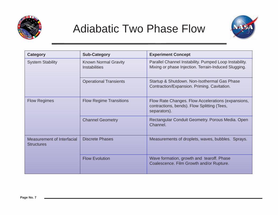
Adiabatic Two Phase Flow
Category Sub-Category Experiment Concept
System Stability Known Normal Gravity Instabilities
Parallel Channel Instability. Pumped Loop Instability.Mixing or phase Injection. Terrain-Induced Slugging.
Operational Transients Startup & Shutdown. Non-Isothermal Gas Phase Contraction/Expansion. Priming. Cavitation.
Flow Regimes Flow Regime Transitions Flow Rate Changes. Flow Accelerations (expansions, contractions, bends). Flow Splitting (Tees, separators).
Channel Geometry Rectangular Conduit Geometry. Porous Media. Open Channel.
Measurement of Interfacial Structures
Discrete Phases Measurements of droplets, waves, bubbles. Sprays.
Flow Evolution Wave formation, growth and tearoff. Phase Coalescence. Film Growth and/or Rupture.

Capillary Flow and Interfacial Phenomena/ Adiabatic Two-Phase Flow
New Concepts1. fluid flow in flexible tubing2. capillary loop with hydrogel3. changing wettability inside capillary
tube4. working fluid mixture behavior within
heat pipes, capillary pumped loop and loop heat pipes.
5. microscale/macroscale interactions6. structured packing/geometry &
spacing of packing7. heat pipe geometries8. thermocapillary convection with
boiling systems (influence of contact angles)
9. scales with biological systems (leaves) (subdividing of veins)
10. scales of applications
11 astro-sweat (impact on hygiene)12 capillary flow limits on extremes,
critical point, superfluid helium13 phase separation14 liquid scavenging15 improved condensing systems to
collect fluid16 capillary mesh structure with smart
materials to evaporate, clean and reuse without external forces
17 phase change materials within a channel geometry, wall materials, microstructure
18 propellant management (LAD)19 bubble free ice cubes
SLPS PS Technology Related Experiments - September 15, 2014 8

Page No. 9
Boiling and Condensation
Category Sub-category Experiment concept
Flow boiling Nucleate boiling to Critical Heat Flux (CHF) and Dry-out
CHF in channels, tubes as function of mass velocity for subcooled, saturated and two-phase inlet conditions. Effects of dissolve gas on above items. Criteria to predict minimum flow velocity required to ensure gravity independent CHF. Pressure drop for subcooled, saturated and two-phase inlet conditions. Flow boiling heat transfer coefficients for subcooled, saturated and two-phase inlet conditions. Wall temperature and heat flux corresponding to onset of boiling. Entrainment and de-entrainment phenomena. Expansion of liquid in vacuum. Flow of superheated and saturated liquids.
Nucleate Boiling to critical Heat Flux (CHF) and Dry-out (for electrohydrodynamically induced flow
Nucleate Boiling to critical Heat Flux (CHF) and Dry-out for capillary induced flow

Page No. 10
Boiling and CondensationContinued
Category Sub-category Experiment concept
Film condensation and drop wise condensation.
Film condensation in channels/tubes; partial to full condensation.
Condensation heat transfer coefficient for all flow regimes. Pressure drop for all flow regimes.
Direct contact condensation on subcooled droplets and agitated liqud-vapor interface.
Film and drop wise condensation on prepared surfaces; contoured and hydrophobic/hydrophilicsurfaces.
Condensation pure vapor and vapor gas mixture on porous surfaces and subtrates.
Evaporation from plane and screened surfaces, porous media, at solid-liquid-vapor contact line with and without forced flow.
Heat pipes. Evaporator/ Condenser/ Phase Separator. Porous Media/Screened Surfaces.

Flow Boiling and Condensation
New Concepts1. Discern the important parameters/dimensionless parameters that govern boiling and
condensation2. Manipulation of flow phase distribution in evaporation in 0-g.3. Manipulation of flow phase distribution in condensation in 0-g.4. Multiple parallel pipes - flow distribution control5. Boiling in curved channels6. Condensation in convergent/divergent channels7. Passively induced flow for boiling and condensation8. Partition of heat transfer mechanisms during flow boiling (evaporation, boiling, single
phase convection, etc.)9. How to enhance boiling heat transfer and CHF in microgravity. Fluids (nano, or
mixtures), surfaces (chemical or mechanical), EHD.10. The influence of cavity size distribution on nucleate boiling11. Two-phase pressure drop across the loop12. Void fraction distribution in two-phase flow in flow boiling13. Diagonstics for flow boiling - local temperatures/pressures, local heat transfer coef.
Both radial and axial.
SLPS PS Technology Related Experiments - September 15, 2014 11
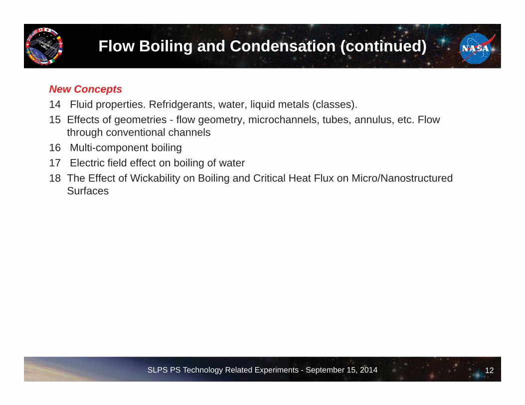
Flow Boiling and Condensation (continued)
New Concepts14 Fluid properties. Refridgerants, water, liquid metals (classes).15 Effects of geometries - flow geometry, microchannels, tubes, annulus, etc. Flow
through conventional channels16 Multi-component boiling17 Electric field effect on boiling of water18 The Effect of Wickability on Boiling and Critical Heat Flux on Micro/Nanostructured
Surfaces
SLPS PS Technology Related Experiments - September 15, 2014 12

Open Science NRA (under consideration)
• Physical Sciences Informatics Ground NRA – 2015
• Fluid Physics, mid 2015, (coordinated solicitation with CASIS)

Glenn Research Center
Accommodation (carrier) Fluid Integrated Rack (FIR)
Upmass (kg)(w/o packing factor)
225 kg (estimated)
Volume (m3)(w/o packing factor)
0.3 m3 (estimated)
Power (kw)(peak)
2500W (estimated)
Crew Time (hrs)(installation/operations)
TBD
Autonomous Operation 6 months
Launch/Increment 12/2017
Project Life Cycle Schedule
ISS Resource Requirements
Flow Boiling and Condensation Experiment (FBCE)PI: Prof. Issam Mudawar, Purdue UniversityCo-I: Dr. Mohammad M Hasan, NASA GRCPS: Dr. David F. Chao, NASA GRCPM: Nancy R Hall, NASA GRC Engineering Team: GRC Engineering
Objectives:Develop experimentally validated, gravity independent, mechanistic model for microgravity annular flow condensation and microgravity flow boiling critical heat flux (CHF).
Relevance/Impact:Key thermal systems and power generating units must be designed to reduce the size, weight and enhance reliability.Two-phase thermal systems utilizing flow boiling and condensation can yield significant enhancement in thermal performanceRelevant to a wide range of systems:
advanced two-phase thermal control system for life support and habitation Rankine cycle, power generation (solar dynamic, nuclear), regenerative fuel cells in space long term storage and transfer of cryogenic propellant
Development Approach:To be developed inhouse by GRC Engineering.Develop an integrated flow boiling/condensation experiment to serve as a primary platform for obtaining two-phase flow and heat transfer data in microgravity with dielectric fluid, normal-perfluorohexane.Engineering models will be used for flight hardware development and flight hardware unit will also be developed.
Critical Heat Flux (CHF) data and model predictions for microgravity and Earth gravity for flow boiling.
Rev. Date: 8/2014
Milestones SCR IDR RDR PDR CDR Ph III Safety FHA Launch Ops complete Final Report
FBCE 11/11 12/12 2/2014 3/2015 6/2016 8/2017 9/2017 12/2017 6/2018 12/2019
14

Flow Boiling and Condensation Experiment (FBCE)
• Thermal management systems responsible for controlling temperature and humidity using Thermal Control System (TCS) consisting of Heat Acquisition, Heat Transport and Heat Rejection hardware.
• Refrigerator/freezer components provide cooling for science experiments and food storage.
• Advanced water recovery systems transfer crew and system wastewater into potable water for crew and system reuse.
15
Rankine Cycle very attractive option for high power systems (> 100 kWe)
15
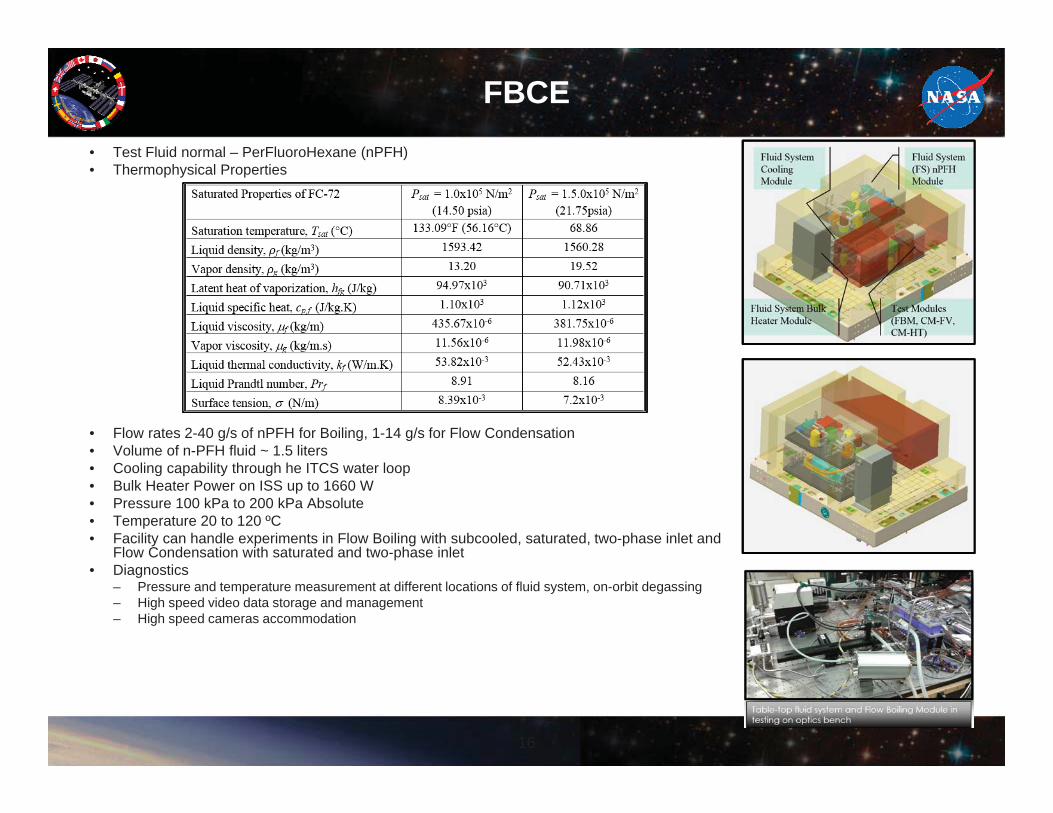
FBCE• Test Fluid normal – PerFluoroHexane (nPFH)• Thermophysical Properties
• Flow rates 2-40 g/s of nPFH for Boiling, 1-14 g/s for Flow Condensation• Volume of n-PFH fluid ~ 1.5 liters• Cooling capability through he ITCS water loop• Bulk Heater Power on ISS up to 1660 W• Pressure 100 kPa to 200 kPa Absolute• Temperature 20 to 120 ºC• Facility can handle experiments in Flow Boiling with subcooled, saturated, two-phase inlet and
Flow Condensation with saturated and two-phase inlet• Diagnostics
– Pressure and temperature measurement at different locations of fluid system, on-orbit degassing– High speed video data storage and management– High speed cameras accommodation
16

Zero-G: 0.125 m/s
1G: 0.125 m/s
1G: 0.25 m/s
1G: 1.25 m/s
FBCE Flow Boiling Module Videos
17
Glenn Research Center
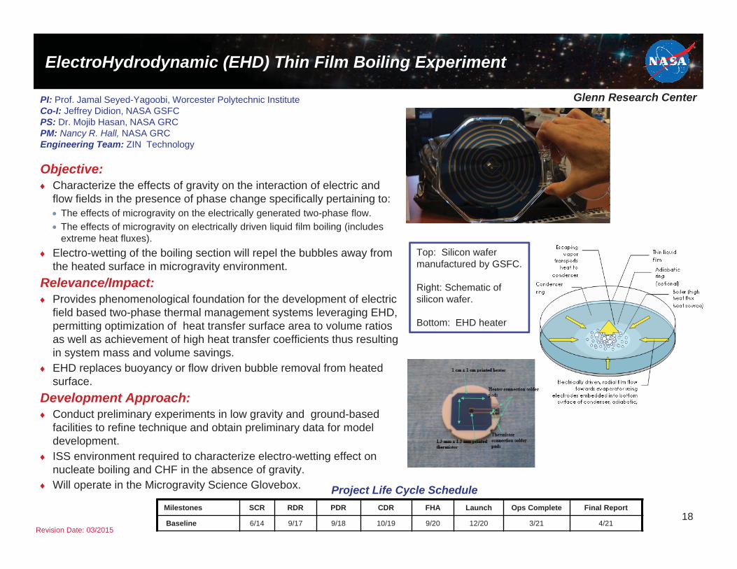
ElectroHydrodynamic (EHD) Thin Film Boiling Experiment
Objective:Characterize the effects of gravity on the interaction of electric and flow fields in the presence of phase change specifically pertaining to:
The effects of microgravity on the electrically generated two-phase flow.The effects of microgravity on electrically driven liquid film boiling (includes extreme heat fluxes).
Electro-wetting of the boiling section will repel the bubbles away from the heated surface in microgravity environment.
Relevance/Impact:Provides phenomenological foundation for the development of electric field based two-phase thermal management systems leveraging EHD, permitting optimization of heat transfer surface area to volume ratios as well as achievement of high heat transfer coefficients thus resulting in system mass and volume savings.EHD replaces buoyancy or flow driven bubble removal from heated surface.
Development Approach:Conduct preliminary experiments in low gravity and ground-based facilities to refine technique and obtain preliminary data for model development.ISS environment required to characterize electro-wetting effect on nucleate boiling and CHF in the absence of gravity.Will operate in the Microgravity Science Glovebox. Project Life Cycle Schedule
PI: Prof. Jamal Seyed-Yagoobi, Worcester Polytechnic InstituteCo-I: Jeffrey Didion, NASA GSFCPS: Dr. Mojib Hasan, NASA GRCPM: Nancy R. Hall, NASA GRCEngineering Team: ZIN Technology
Milestones SCR RDR PDR CDR FHA Launch Ops Complete Final Report
Baseline 6/14 9/17 9/18 10/19 9/20 12/20 3/21 4/21Revision Date: 03/2015
Top: Silicon wafer manufactured by GSFC.
Right: Schematic of silicon wafer.
Bottom: EHD heater
18

Glenn Research Center
Zero Boil-Off Tank (ZBOT) Experiment: Fluid Mixing
Objective:Develop a small-scale simulant-fluid ISS flight experiment to study storage tank pressurization & pressure reduction through fluid mixing in microgravity.Gather high fidelity microgravity data under known/controlled conditions for verification & validation of storage tank CFD models.Formulate much-needed microgravity empirical correlations for thermal stratification, pressurization, liquid mixing, pressure reduction, and interfacial heat and mass transfer.Assess the engineering feasibility of dynamic Zero-Boil-Off (ZBO) pressure control for microgravity applications.
Relevance/Impact:Reduce propellant launch mass (cost) and decrease risks for future space missions by aiding the development of dynamic pressure control schemes for long-term storage of cryogenic fluids.Increase design reliability by providing archival data for benchmarking and improving CFD models/codes used by the Cryogenic Fluids Management Community (CFM) and the Aerospace Companies for future (ground-tested-only) tank designs.
Development Approach:Ground Phase: Develop ground-based experiment and obtain 1-g data for tank pressurization and pressure reduction.Flight Phase: Develop ISS experiment/hardware and obtain microgravity data for tank pressurization and pressure reduction.Modeling: Develop a state-of-the art two-phase CFD model for tank pressurization and pressure control.Validation: Validate and Verify the CFD model with microgravity and 1g data.Scale-Up: Use the validated CFD model and empirical correlations derived from the 1g and microgravity data for scale-up tank design.
Accommodation (carrier)
Microgravity Science Glovebox (MSG)
Upmass (kg)(w/o packing factor)
114 kg
Volume (m3)(w/o packing factor)
0.23 m3
Power (kw)(peak)
0.445 kw (0.314 kw max continuous)
Crew Time (hrs)(installation/operations)
13 hrs. total
Launch/Increment Launch: SPX-7/45 & 46 (Ops)
ISS Resource Requirements
Revision Date: 8/12/14
PI: Dr. Mohammad Kassemi, NCSER/GRCCo-I: Dr. David Chato, NASA GRCPS: John McQuillen, NASA GRCPM: William Sheredy, NASA GRCEngineering Team: ZIN Technologies, Inc.
ZBOT Engineering Model in the MSG Work Volume
Mockup
CFD Model Prediction: Temp & Flow Fields in
Microgravity
Project Life Cycle ScheduleMilestones SCR RDR PDR CDR VRR Phase III Safety FHA Launch Ops Return Final Report
Actual/ Baseline 7/06 6/08 2/10 12/12 3/14 11/14 3/15 6/15 10/15 – 2/16 TBD 2/17
19

Glenn Research Center
2
Test Tank10 cm Diameter20 cm LongHemispherical Cap1.3 L total Volume
Test Fluid: Perfluoro-normal-Pentane• Density ~ 1.6 g/ml• Viscosity ~ 0.4 cP• Surface Tension ~ 15 dynes/cP• Normal Boiling Pt: 30 CJet Flow Rates: 0.4 to 3 ml/sStrip Heater Power: 0 to 1 WPressure: 60 - 200 kPaTemperature 25 - 50 CFill Levels 70 to 90%Ullage bubble: Vapor &/or Noncondensible GasDiagnostics• Pressure Sensor ±0.34 kPa• Several RTD’s ±0.1 C in fluid, on inside and
outside tank wall• High Resolution Camera and Visible light
backlight• Laser and Particle Imaging Velocimetry
ZBOT

Glenn Research Center
Zero Boil-Off Tank-2 (ZBOT-2) Experiment: Noncondensable Gas Effects
Objective:Noncondensable gases can significantly affect Zero-Boil-Off (ZBO) storage tank pressurization and pressure reduction, especially, in microgravity with the danger of deteriorating tank pressure controlThere are currently no microgravity data on the effect of Non-condensable on evaporation/condensation rates in microgravity.This research will investigate three important effects of non-condensable gases on the transport and phase change phenomena that control tank pressure. These effects can be best studied when they are readily unmasked in microgravity:
The transport barrier created by non-condensable in the ullage during microgravity pressurization and pressure control. The creation of thermocapillary convection induced by non-condensable and its effect on mixing, stratification and destratification in the liquid.The penetration of noncondensbles into the Knudsen layer and its impact on condensation during microgravity pressure control.
Development Approach:Flight Experiment: Modify the ZBOT-1 hardware and diagnostics for non-condensable gas studies. Obtain microgravity data to determine the effectof the noncondensables on tank pressurization, thermal de-stratification,and pressure reduction through mixing/cooling in microgravity.Theoretical Work: Expand the existing ZBOT-1 two-phase CFD model byincorporating the non-condensable gas kinetics, species transport, andMarangoni convection submodels. Validate the expanded two-phaseCFD model and submodels.
21
Accommodation (carrier) Microgravity Science Glovebox
Upmass (kg)(w/o packing factor)
50 Kg*
Volume (m3)(w/o packing factor)
0.1 m3*
Power (kw)(peak)
0.445 kw (0.314 kw max continuous)
Crew Time (hrs)(installation/operations)
13 hrs. total
Launch/Increment Launch: 2020
Project Life Cycle ScheduleMilestones Kickoff SCR/RDR PDR CDR/VRR Phase III Safety FHA Launch Ops Complete Final Report
Actual/ Baseline 10/15 9/16 9/17 9/18 7/19 9/19 1/20 3/20 3/21
ISS Resource Requirements
Revision Date: 8/12/14
Hand-in-Hand Microgravity & 1G Experimentation & Computational Modeling
PI: Dr. Mohammad Kassemi, NCSER/GRCCo-I: Dr. David Chato, NASA GRCPS: John McQuillen, NASA GRCPM: William Sheredy, NASA GRCEngineering Team: ZIN Technologies, Inc.
NonCondensable gas impedes pressure reduction in space
Residual noncondensable forms transport barrier for
vapor condensation
*ZBOT-2 new hardware only

Glenn Research Center
Zero Boil-Off Tank-3 (ZBOT-3) Experiment: Active Cooling
22
Project Life Cycle Schedule
ISS Resource Requirements
Revision Date: 8/12/14
PI: Dr. Mohammad Kassemi, NCSER/GRCCo-I: Dr. David Chato, NASA GRCPS: John McQuillen, NASA GRCPM: William Sheredy, NASA GRCEngineering Team: ZIN Technologies, Inc.
Sub-Cooled Jet: Mixing & Cooling
LAD
Broad Area Cooling: Radiative Loss to Cooled
Isolation-Jacket
NonCondensable Pressurant
Spray-Bar: Droplet Mixing & Cooling
Milestones Kickoff SCR/RDR PDR CDR/VRR Phase III Safety FHA Launch Ops Complete Final Report
Actual/ Baseline 10/18 9/19 9/20 9/21 7/22 9/22 1/23 3/23 3/24
Accommodation (carrier) Microgravity Science Glovebox
Upmass (kg)(w/o packing factor)
50 Kg*
Volume (m3)(w/o packing factor)
0.1 m3*
Power (kw)(peak)
0.445 kw (0.314 kw max continuous)
Crew Time (hrs)(installation/operations)
13 hrs. total
Launch/Increment Launch: 2023
*ZBOT-3 new hardware only
Objective:The Spray-Bar-Droplet and Jet-Mixing active cooling pressure control mechanism have not been tested in microgravity.There are no microgravity data on droplet dispersion, transport, and phase change although all of these phenomena are strongly gravity-dependent.This experiment will perform temperature, pressure and non-intrusive velocity measurements and phase and droplet visualization to:
examine the break-up and heat & mass transport characteristics of droplets in microgravityrecord the residence time of the droplets in the ullage in microgravity compare the thermal de-stratification and pressure reduction time constants of spray-bar and jet mixing mechanisms at different fill-levels, heat inputs, and jet velocities in presence and absence of non-condensables.
Development Approach:Flight Experiment: Modify the ZBOT-1/2 hardware to incorporatespray bar and broad area cooling technologies and diagnostics forthese studies. Obtain microgravity data to determine the effectivenessof the different active pressure control strategies in microgravity.Theoretical Work: Expand the existing ZBOT-1/2 two-phase CFDmodel by incorporating spray-bar Lagrangian/Eulerian droplet phasechange submodels. Validate the expanded two-phase CFD model andsubmodels.
Glenn Research Center
23
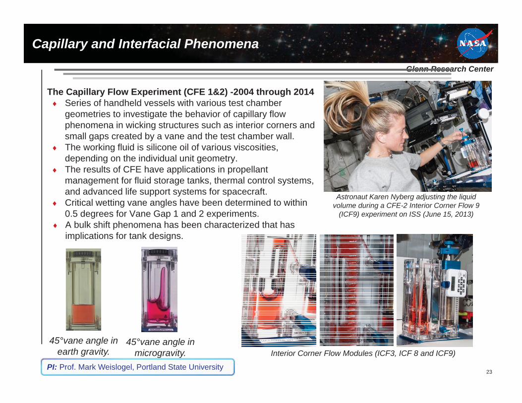
The Capillary Flow Experiment (CFE 1&2) -2004 through 2014 Series of handheld vessels with various test chamber geometries to investigate the behavior of capillary flow phenomena in wicking structures such as interior corners and small gaps created by a vane and the test chamber wall.The working fluid is silicone oil of various viscosities, depending on the individual unit geometry.The results of CFE have applications in propellant management for fluid storage tanks, thermal control systems, and advanced life support systems for spacecraft.Critical wetting vane angles have been determined to within 0.5 degrees for Vane Gap 1 and 2 experiments.A bulk shift phenomena has been characterized that has implications for tank designs.
Astronaut Karen Nyberg adjusting the liquid volume during a CFE-2 Interior Corner Flow 9
(ICF9) experiment on ISS (June 15, 2013)
45°vane angle in microgravity.
45°vane angle in earth gravity. Interior Corner Flow Modules (ICF3, ICF 8 and ICF9)
PI: Prof. Mark Weislogel, Portland State University
Capillary and Interfacial Phenomena
Glenn Research Center
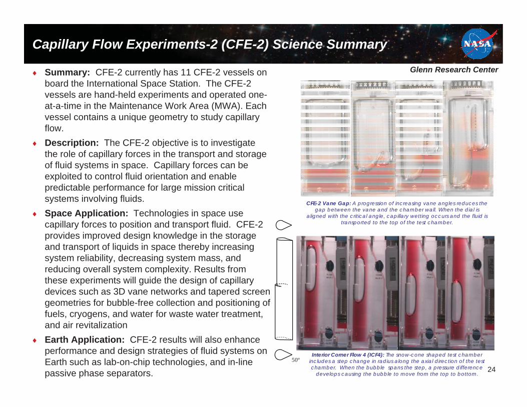
Capillary Flow Experiments-2 (CFE-2) Science Summary
Summary: CFE-2 currently has 11 CFE-2 vessels on board the International Space Station. The CFE-2 vessels are hand-held experiments and operated one-at-a-time in the Maintenance Work Area (MWA). Each vessel contains a unique geometry to study capillary flow.Description: The CFE-2 objective is to investigate the role of capillary forces in the transport and storage of fluid systems in space. Capillary forces can be exploited to control fluid orientation and enable predictable performance for large mission critical systems involving fluids.Space Application: Technologies in space use capillary forces to position and transport fluid. CFE-2 provides improved design knowledge in the storage and transport of liquids in space thereby increasing system reliability, decreasing system mass, and reducing overall system complexity. Results from these experiments will guide the design of capillary devices such as 3D vane networks and tapered screen geometries for bubble-free collection and positioning of fuels, cryogens, and water for waste water treatment, and air revitalizationEarth Application: CFE-2 results will also enhance performance and design strategies of fluid systems on Earth such as lab-on-chip technologies, and in-line passive phase separators.
50º
CFE-2 Vane Gap: A progression of increasing vane angles reduces the gap between the vane and the chamber wall. When the dial is
aligned with the critical angle, capillary wetting occurs and the fluid is transported to the top of the test chamber.
Interior Corner Flow 4 (ICF4): The snow-cone shaped test chamber includes a step change in radius along the axial direction of the test chamber. When the bubble spans the step, a pressure difference
develops causing the bubble to move from the top to bottom.24

Glenn Research Center
Two-Phase Flow Separator Experiment (TPFSE)
Objectives:Develop and evaluate the performance of a gas-liquid phase separator suitable for space applications including the transient and steady-state instability behaviorUtilize DYNAFLOW’s DYNASWIRL® technology to generate high intensity swirl flow with no moving partsOperate close to cavitation inception in the core of the vortex line for efficient separation at low void fractions (DYNAFLOW)Validate and verify the multiphase CFD modeling approaches that have been developed to simulate the complicated two-phase transport processes associated with phase separation in microgravity. (CWRU)
Relevance/Impact:Gas-liquid separators are a critical component in Active Thermal Control Systems (ATCS) and Environmental Control and Life Support Systems (ECLSS) applications.Requiring no moving parts, cyclonic phase separation improves performance, increases component life, and significantly reduces cost and weight while improving reliability.
Development Approach:TPFSE is a joint investigation to study cyclonic phase separation with two different design concepts. The DYNAFLOW conceptincludes an inner chamber with tangential slots. The CWRU concept includes a movable baffle plate and interchangeable injection nozzle.
25
PI: Dr. Georges Chahine, DYNAFLOW, Inc. PI: Prof. Yasuhiro Kamotani, Case Western Reserve UniversityCo-I: Prof. Jaikrishnan Kadambi, Case Western Reserve UniversityPS: Lauren Sharp, NASA GRC PM: Nang Pham, NASA GRC
The TPFSE test sections, DYNAFLOW (left) and CWRU (right),with containment for integration in a test rig for testing
Milestones SCR RDR PDR CDR Phase III Safety
FHA Launch Ops complete Final Report
5/2013 9/2016 10/2017 12/2018 5/2020 8/2020 1/2021 2021 Return +12mo
ISS Resource RequirementsAccommodation (carrier)
Fluids Integrated Rack (FIR)
Upmass (kg)(w/o packing factor)
210 (prelim est.)
Volume (m3)(w/o packing factor)
0.247 (prelim est.)
Power (kw)(peak)
2.1 (prelim est.)
Crew Time (hrs)(installation/operations)
10hrs (prelim est. – 5hrs setup & 5hrs disassemble; 3hrs (prelim est. - Test Section, Diagnostic Module & SSDs swap out; 200hrs (prelim est. - autonomous ops)
Launch/Increment TBD

Glenn Research Center
The DYNAFLOW concept – (a) top view, (b) side view – illustrates the inner and outer chambersalong with the two phase inlet and gas/liquid outlets. A science image (c) – an enlarged view of
the gas core within the inner chamber shows coalescence during a low g aircraft flight.
The CWRU concept – (d) top view, (e) side view – illustrates a single chamber with a movablebaffle plate, the two phase injection port, and the gas/liquid outlets. A science image (f) ofthe gas core during a low g aircraft flight. The baffle plate bounds the gas core to ensure no
gas enters the liquid outlet.
Two-Phase Flow Separator Experiment (TPFSE)
Science Summary: The DYNAFLOW and CWRU concepts both utilize inertia from a tangentially injected two-phase flow to separate the liquid from the gas phase.These cyclonic two-phase separator concepts were tested during flights on the reduced gravity aircraft in September 2013.During low-g operation in the reduced gravity aircraft:
A gas-liquid mixture entered the test section through the injection port.The liquid (denser) phase accumulated to form a layer along the chamber wall, while the gas (less dense) formed a vortex core in the center of the chamber.Large gas bubbles coalesced and formed a gas core.Successful phase separation was observed as liquid and gas were extracted at opposite ends of each test section.
Test parameters, including liquid flow rate, gas flow rate, were varied during the reduced gravity aircraft campaign to understand the performance and operability limits of each phase separator.
26
Gasoutlet
Liquidoutlet
Two phaseinlet
Innerchamber
wall
Outerchamber
wall
(a)
(b) (c)
Gas outlet
Liquid outlet
Gas core
Two phaseinlet
Moveablebaffleplate
Two phaseinlet
gascore
(d)
(e) (f)

Glenn Research Center
Gas-Liquid Separation Devices
27
Reduced Gravity Bubble Vortex
Cyclonic Concepts
Two-Phase Flow Separator Experiment (TPFSE) – 2018 • Two PI Teams will share common test hardware to study different aspects.• Will address the design and performance of passive two-phase flow separator
technologies.• Determine range of flow rates for acceptable performance. • Quantify the effect of fluid properties and separator geometry.• Determine separator response and stability envelope to startup, shutdown and liquid
slugging conditions.• Passive separation is critical to high reliability and low power gas-liquid systems for used
in thermal control and life support.
Pumped Separator for PBRE PI: Dr. Georges Chahine and Xiongjun Wu, DynaFlow, Inc. PI: Prof. Yasuhiro Kamotani, Case Western Reserve UniversityCo-I: Prof. Jaikrishnan Kadambi, Case Western Reserve University

Glenn Research Center
Packed Bed Reactor Experiment (PBRE)
Milestones SCR RDR PDR CDR FHA Launch Ops Final Report
6/2005 2/2011 12/2011 3/2013 3/2015 8/2015 Inc. 47 Return +12mo
Project Life Cycle Schedule
Objectives:Investigate role and effects of gravity on hydrodynamics of gas-liquid flow through porous media.Develop/validate scaling laws and design tools for future packed bed reactors in 0-g and partial-g environments, including start up and transient operations.Identify strategies to recover single-phase beds from undesired trapped gas bubbles.
PI: Dr. Brian Motil, NASA GRCCo-Is: Prof. Vemuri Balakotaiah, University of Houston
& Julie L Mitchell (JSC)PS: Dr. Enrique Ramé, NCSER-NASA GRCPM: Nang Pham, NASA, GRC
Relevance/Impact:Directly aligns with high priorities from the NRC Decadal survey on Biological and Physical Sciences (1) and the NRC 2000 report on Microgravity Research in Support of Technologies for the Human Exploration and Development of Space and Planetary Bodies (2):
AP-2: Provides a study of a critical multiphase flow component for life support systems (1)TSES-6: Provides a fundamental study in porous media under microgravity conditions (1)T-6: Lack of understanding of partial g on life support systems (1)T-22: lack of closed loop water recovery (1)Multiphase flow and heat transfer: Recomm. #1, 2 & 7 p. 181 (2)
Two-phase components are critical to life support and thermal control systems.Development Approach:
Completed extensive (but time-limited) low-G aircraft tests.Two packing types: wetting and non-wetting to probe wettability effects.Engineering model hardware and Proto-flight unit.Develop on-orbit replaceable test section to extend experiment capabilities for future development of two-phase components/devices.
Accommodation(carrier)
Microgravity Science Glovebox
Upmass (w/o packing factor)
125 kg
Volume (w/o packing factor) 0.150 m3
Peak Power 0.75 kW
Crew Time 8 hours (4hrs setup; 4hrs disassemble)2 hours (Test Module and SSDs change-out)
Autonomous Ops 200 hours
Launch/Increment SPACEX8/Inc 44
ISS Resource Requirements
PBRE Engineering Model Unit. The column is packed with 3mm glass beads
Packed column
28

Glenn Research CenterPacked Bed Overview
Gas-Liquid mix out
Gas and Liquid Injection manifold
Engineering Model column packed with 3-mm Teflon beads in the ZIN fabrication area. An identical column is packed with 3-mm glass beads.
Packed Bed Reactor Experiment (PBRE)
Pressure drop for 2-phase flow in micro-g drastically different from 1-gFlow regime boundaries in micro-g fundamentally different from 1-g:
Bubbly-to-Pulse Flow regime boundary exists only in micro-gFor similar gas and liquid flows, the 1-g flow regime boundary is trickle-to-pulse
Pressure drop and Flow Regime boundary correlations need to be recreated in micro-g before reliable design methods for 2-phase flow in packed beds can be developed
29

Glenn Research CenterPI: TBD from MSFC (2 PIs)Co-I: Dr. Brian Motil, NASA, GRCPS: Dr. Enrique Ramé, NCSER-NASA GRCPM: Nang Pham, NASA, GRC
Packed Bed Reactor Experiment - Applied: PBRE-A (proposed)
Objectives:Study the role and effects of gravity on hydrodynamics of gas-liquid flow through realistic packed beds
Selected Applications:Aqueous-Phase Catalytic Oxidation (APCO) System
Prototype catalytic oxidation system (post-processor for water recovery systems)Microbial Check Valve (MCV)
Potable water with 2 ppm iodine to prevent microbial growthActivated Carbon/Ion Exchange (ACTEX)
Removes iodine from potable water before crew consumptionIon Exchange for Calcium Removal (in development)
Removes Ca++ ions from urine to prevent calcium sulfate precipitation in the ISS Urine Processor Assy
Volatile Removal Assembly (VRA)A catalytic oxidation system for water treatment
IntraVenous Fluid GENeration (IVGEN)A deionizing resin bed to remove contaminants to standards of the United States Pharmacopeia (USP)
Development Approach:Utilize PBRE hardware capability to replace test sections to expand testing to more realistic packed bedsDevelop test sections with realistic packing used in current or future space applications
IVGEN packed column
One of the packed columns used in the Biological Water Processors
(in development)
30

Page No. 31
BACK - UP

Glenn Research Center
Constrained Vapor Bubble-2 (CVB-2)WBS: 904211.04.02.20.06
Objective:Determine the fundamental transport in a prototype wickless heat pipe including the overall stability, flow characteristics, average heat transfer coefficient in the evaporator, and heat conductance as a function of heat flow rate and vapor volume for a complex (~94% Pentane/ 6% Iso-Hexane) binary fluid in microgravity.
Relevance/Impact:Results will lead to optimally designed heat pipes (for ground and space) that will operate at full capacity and provide significant weight savings.CVB-2 will provide the understanding of the maximum achievable performance of simplified heat pipes based on corner flows using a complex fluid.22 papers and publications from original CVB, exceeded science and engineering objectives. Results in Chemical Engineering Textbook Transport Phenomena Fundamentals , Joel Plawsky, 2010 and Second edition 2013.
Development Approach:The CVB/LMM is designed for autonomous ground operation. Crew time is required for initial installation and check out in the FIR) sample change out, and removal from FIR.Re-fly CVB 30mm module with binary mixture.
Accommodation (carrier) Fluids Integrated Rack (FIR)/LMM
Upmass (kg)(w/o packing factor)
6 Kg for CVB-2
Volume (m3)(w/o packing factor)
0.009 CVB-2
Power (kw)(peak)
0.5kw for CVB/LMM1.1 kw for FIR/CVB/LMM
Crew Time (hrs)(installation/operations)
5 Hours
Autonomous Operations 250 hrs/module
Launch/Increment ATV4/Increment 35-36, OPS – 35-36
Project Life Cycle ScheduleMilestones SCR RDR PDR CDR VRR Safety FHA Launch Ops Return Final Report
Actual/ Baseline 9/97CVB
8/12CVB-2
2/02LMM/CVB
12/03LMM/CVB
8/04LMM/CVB
Phase III 11/12
1/13 6/13 Inc 35-38 10/2014 2015
ISS Resource Requirements
PI: Prof. Joel L. Plawsky, Rensselaer Polytechnic InstituteCo-I: Prof. Peter C. Wayner, Jr., Rensselaer Polytechnic InstitutePS: Dr. David F. Chao, NASA GRCPM: Ronald Sicker, NASA GRC Engineering Team: ZIN Technologies, Inc.
Revision Date 03/29/2013
Astronaut T. J. Creamer installing the first CVB Module on March 20, 2010.
(Top) 30mm CVB pentane modulefull scale. (Bottom) 10x images ofthe condensation and vapor region.
32

Glenn Research Center
Heat Pipe Experiment - Loop (HPE-L) (Proposed)
Objective:Development and spaceflight test of a prototype loop heat pipe facility that would be used to cool critical electronic and life support systems aboard spacecraft.Novel design based on the Constrained Vapor Bubble that provides for complete control of the vapor-liquid interface using wickless, channel geometry designs, capillary flow, and complex fluid mixtures to eliminate the need for wicks and minimize Marangoni stresses.
Relevance/Impact:Contains no moving parts to fail and can be made lightweight.Offers improved performance, reliability, and operability, especially in microgravity.Is directly applicable for cooling critical civilian and military components.Designed to to manipulate the vapor-liquid interface using specially designed cross sectional shapes and Marangoni forces driven by the heater and condenser sections.Producing paper claiming discovery of new limit to heat pipe operation called the Marangoni limit
Development Approach:The CVB/LMM is designed for autonomous operation through scripts and ground commands.Crew time is required for initial installation and check out in the Fluids Integrated Rack (FIR), sample change out, and removal from FIR.
Project Life Cycle Schedule
Revision Date 08/14/2014
PI: Prof. Joel L. Plawsky, Rensselaer Polytechnic InstituteCo-I: Dr. David F. Chao, NASA GRC, Dr. Brian J. Motil, NASA GRCProject Scientist: Eric Golliher, NASA GRCPM: Ronald Sicker, NASA GRC Engineering Team: ZIN Technologies, Inc.
Milestones SCR RDR PDR CDR FHA Launch Ops complete Final Report
Actual/ Baseline 2/2018 11/2018 11/2019 11/2020 12/2021 3/2022 6/2023 6/2024
Concept drawing from: NIAC Proposal NNH14ZOAOO1N-14NIAC (Plawsky, Motil, Chao)
Loop heat pipe configuration
Fluids used: pentane/isohexane mixtures, water/isopropanol mixtures
CapillaryDrivenCorner Flow
Polygonal CuvetteShape
33
Glenn Research Center
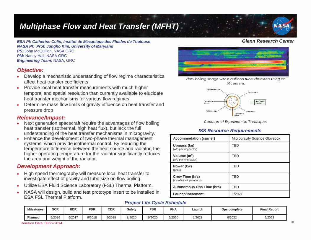
Multiphase Flow and Heat Transfer (MFHT)
Objective:Develop a mechanistic understanding of flow regime characteristics affect heat transfer coefficientsProvide local heat transfer measurements with much higher temporal and spatial resolution than currently available to elucidate heat transfer mechanisms for various flow regimes.Determine mass flow limits of gravity influence on heat transfer and pressure drop
Relevance/Impact:Next generation spacecraft require the advantages of flow boiling heat transfer (isothermal, high heat flux), but lack the full understanding of the heat transfer mechanisms in microgravity.Enhance the development of two-phase thermal management systems, which provide isothermal control. By reducing the temperature difference between the heat source and radiator, the higher operating temperature for the radiator significantly reduces the area and weight of the radiator.
Development Approach:High speed thermography will measure local heat transfer to investigate effect of gravity and tube size on flow boiling.Utilize ESA Fluid Science Laboratory (FSL) Thermal Platform.NASA will design, build and test prototype insert to be installed in ESA FSL Thermal Platform.
34
Project Life Cycle Schedule
ISS Resource Requirements
Revision Date: 08/22/2014
Milestones SCR RDR PDR CDR Safety PSR FHA Launch Ops complete Final Report
Planned 9/2016 9/2017 9/2018 9/2019 8/2020 9/2020 9/2020 1/2021 6/2022 6/2023
ESA PI: Catherine Colin, Institut de Mécanique des Fluides de ToulouseNASA PI: Prof. Jungho Kim, University of MarylandPS: John McQuillen, NASA GRCPM: Nancy Hall, NASA GRCEngineering Team: NASA, GRC
Accommodation (carrier) Microgravity Science Glovebox
Upmass (kg)(w/o packing factor)
TBD
Volume (m3)(w/o packing factor)
TBD
Power (kw)(peak)
TBD
Crew Time (hrs)(installation/operations)
TBD
Autonomous Ops Time (hrs) TBD
Launch/Increment 1/2021
Flow boiling Image within a silicon tube visualized using an IR camera.
Concept of Experimental Technique.
Glenn Research Center
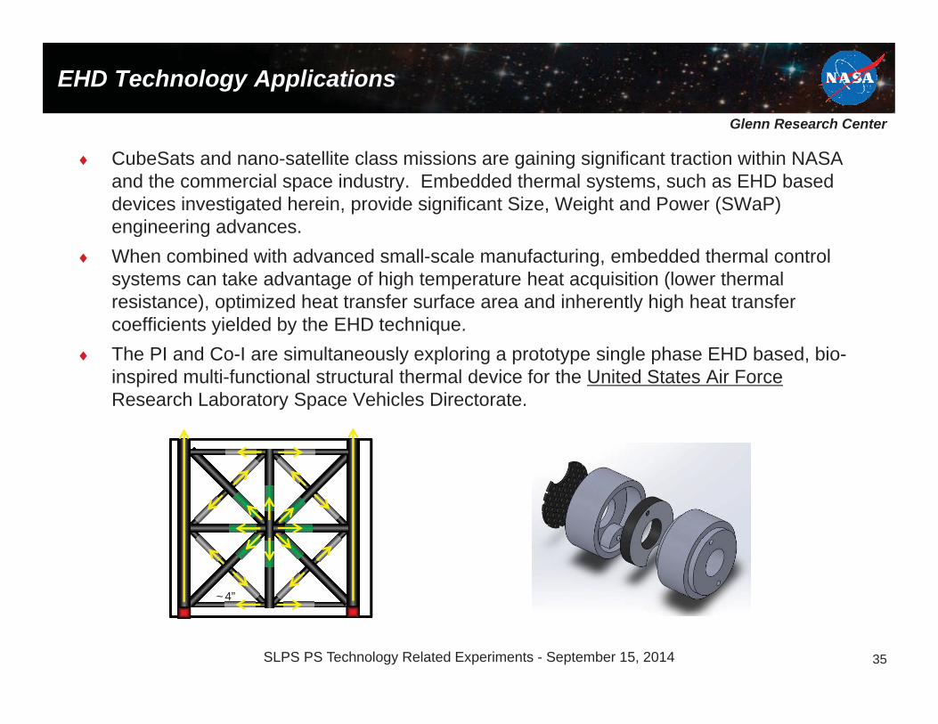
EHD Technology Applications
CubeSats and nano-satellite class missions are gaining significant traction within NASA and the commercial space industry. Embedded thermal systems, such as EHD based devices investigated herein, provide significant Size, Weight and Power (SWaP)engineering advances.When combined with advanced small-scale manufacturing, embedded thermal control systems can take advantage of high temperature heat acquisition (lower thermal resistance), optimized heat transfer surface area and inherently high heat transfer coefficients yielded by the EHD technique.The PI and Co-I are simultaneously exploring a prototype single phase EHD based, bio-inspired multi-functional structural thermal device for the United States Air ForceResearch Laboratory Space Vehicles Directorate.
~4”
35SLPS PS Technology Related Experiments - September 15, 2014

Glenn Research Center
Pool Boiling (for EHD justification)
This figure illustrates remarkable differences in pool boiling between normal gravity and microgravity conditions.
In normal gravity the heater surface is covered with a large number of small bubbles that rise due to buoyancy.In microgravity a large bubble of vapor appears at the top of the heater.Small bubbles merge into the large one at the heater surface.These difference give rise to significant changes in heat transfer coefficient and critical or buoyant heat flux.
36

Glenn Research Center
Purifier
Space Technology Applications (for Packed Beds)
IntraVenous Fluid GENeration (IVGEN): demonstrated a microgravity compatible water purification and pharmaceutical mixing system.Successfully flown in March, 2010.Deionizing resin bed:
Remove contaminants from feedstock waterMeet purity level standards of the United States Pharmacopeia (USP)
Required minimal liquid velocity to clear bubbles from packed bed and minimal flow rate to meet purified water production requirements.Model was used for:
~6” packed bed5/8” inner diameter0.4 to 0.5 diameter packingActual flow rate: 28 ml/min“Equivalent flow”: 15.8 liter/min
37

Page No. 38
International Cooperation:NASA Physical Sciences Research
• Multilateral Engagement: International Microgravity Strategic Planning Group (IMSPG) – Coordinate the development and use of ISS research among
microgravity research programs in areas of common interest to maximize the productivity of microgravity research internationally.
– Meets once a year on the margins of the annual meeting of the American Society for Gravitational and Space-Research
– Members: ASI, CNES, CSA, ESA, DLR, JAXA, NASA and Roscosmos
– Priority Areas for International Coordination Include:• All disciplines within Physical Sciences• Sharing facilities, experiment-specific hardware, data, etc.

Page No. 39
International Cooperation:NASA Physical Sciences Research
• Bilateral Engagement: NASA works directly with other space agencies or research institutions - especially the ISS partner agencies (examples):
– ESA: Collaborative research in the ESA Material Science Laboratory (MSL) furnaces using ESA-developed cartridges and supporting development of NASA cartridges, Electro Magnetic Levitation (EML) facility and Microwave Ground link stations for the AtomicClock Ensemble in Space Experiment. (common and unilateral objectives)
– ASI: Collaboration to study Biofuels using the NASA Combustion Integrated Rack
– CNES: Joint use of a CNES DECLIC hardware for joint investigations in fluid physics and/or solidification of transparent materials.
– JAXA: Cooperation on the combustion of fuel droplets using NASA’s Combustion Integrated Rack (CIR) and JAXA’s Group Combustion Experiment Module (GCEM) hardware to perform experiments (common and unilateral objectives).
– Russia: OASIS – Scientists’ protocol and ISS Program protocol – study the unique behavior of liquid crystals in microgravity using the NASA Microgravity Sciences Glovebox
Page No. 40
Benefits of International Cooperationon ISS Research
• The ISS laboratory has reached a mature configuration including many unique research facilities provided by each International Partner.
• To maximize the utilization of these facilities, the partners are pursuing cooperative arrangements where partners perform investigations in each other’s facilities and utilize each others on-orbit (and ground) resources.
• Benefits:– Allows access to more researchers from more countries– Fosters cooperative research objectives between partners– Allows complementary research to be performed in multiple facilities– Facilitates wide distribution of research data– Avoids duplication of facilities/capabilities in the severely limited volume of the ISS– Reduces crew training and operations planning by re-using existing
facilities/capabilities– Reduces overall cost of research– Maximizes the return on investment for each facility

Page No. 41
International Collaboration
• International Collaboration for each Physical Sciences Discipline:– Biophysics– Combustion Science– Complex Fluids– Fluid Physics– Fundamental Physics– Materials Science

Page No. 42
NASA’s International Cooperation in Physical Sciences on ISS
Theme Acronym Experiment
International PartnersESA JAXA CSA ROS
COSMOS
CNES DLR ASI KARI
Bio
phys
ics
PROTEIN Protein Nucleation and Growth Kinetics Experiment (Vekilov) S
Nano Step-2 Solution Crystallization Observation Facility, (SCOF), Suzuki, (Vekilov)
S
Delucas
Effect of MacromolecularTransport on Protein Crystillization
P
Vekilov
Solution Convection and Nucleation Precursors in Protein Crystallization
SnellGrowth Rate Dispersion ofBiological Crystal Samples
HirsaAmyloid Fibril Formation in Microgravity
Blue Print: Experiment Acronyms in Blue are Sponsored by non-NASA Agency S: SponsorP: Participant
42

Page No. 43
NASA’s International Cooperation in Physical Sciences on ISS
Theme Acronym ExperimentInternational Partners
ESA JAXA CSA ROSCOSMOS
CNES DLR ASI KARI
Com
bust
ion
Sci
ence
SOFIE Solid FLAmabiity of Materials Experiment
BASS-2 Burning and Suppression of Solids
FLEX-2 Flame Extinguishment Experiment–2
FLEX-2J Flame Extinguishment experiment– with JAXA P
SCE Solid Combustion Expt. - 2012JAXA AO, Fujita,Olsen..(2015, MSPR)
S
GCE Group Combustion Experiment -2D droplet array S
FLEX-ICE Flame Extinguishment experiment–Italian Combustion Experiment
P
ISFSS Int’l Standard of Fire Safety in Space – 2012 JAXA AO, Fujita,Olsen,etal (2016,MSPR)
S
ACME Advanced Combustion via Microgravity Experiments (Gaseous)
SCWO(planned)
Super Critical Water Oxidation P P
SCWM Super Critical Salt Water Mixture Experiment S
Blue Print: Experiment Acronyms in Blue are Sponsored by non-NASA Agency S: Sponsor, P: Participant
43
Page No. 44
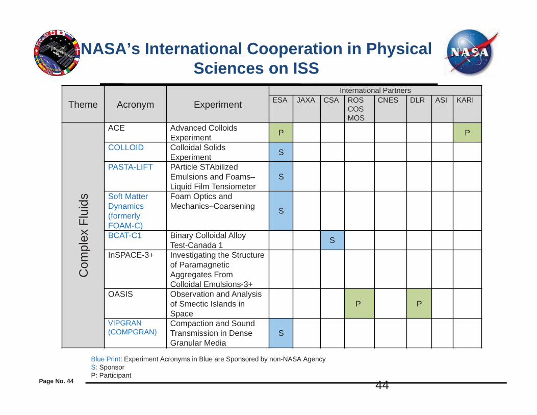
NASA’s International Cooperation in Physical Sciences on ISS
Theme Acronym ExperimentInternational Partners
ESA JAXA CSA ROSCOSMOS
CNES DLR ASI KARI
Com
plex
Flu
ids
ACE Advanced Colloids Experiment P P
COLLOID Colloidal SolidsExperiment S
PASTA-LIFT PArticle STAbilizedEmulsions and Foams–Liquid Film Tensiometer
S
Soft Matter Dynamics(formerlyFOAM-C)
Foam Optics and Mechanics–Coarsening S
BCAT-C1 Binary Colloidal Alloy Test-Canada 1 S
InSPACE-3+ Investigating the Structure of Paramagnetic Aggregates From Colloidal Emulsions-3+
OASIS Observation and Analysis of Smectic Islands in Space
P P
VIPGRAN(COMPGRAN)
Compaction and Sound Transmission in Dense Granular Media
S
Blue Print: Experiment Acronyms in Blue are Sponsored by non-NASA Agency S: SponsorP: Participant
44

Page No. 45
NASA’s International Cooperationin Physical Sciences on ISS
Theme Acronym ExperimentInternational Partners
ESA JAXA CSA ROSCOSMOS
CNES DLR ASI KARI
Flui
d P
hysi
cs
FBCE Flow Boiling and Condensation Experiment
RUBI Reference mUltiscale Boiling Investigation S
MFHT Multiphase Flow with Heat Transfer S
ZBOT Zero Boiloff ExperimentZBOT-2 Zero Boiloff Experiment–2CCF Capillary Channel Flow SCFE-2 Capillary Flow Experiment–2DOLFIN II Dynamics of Liquid Film/ Complex
Wall Interaction S
CVB-2 Constrained Vapor Bubble–2EHD Electro-hydrodynamic flow
PBRE Packed Bed Reactor Experiment
TPFSE Two Phase Flow Separator Experiment
JEREMI JAXA Marangoni Flow Experiment (Narayanan, Kamotani) S
VIPIL-Faraday(Planned)
ESA Vibration in Liquids experiment, planning stages (Narayanan)
S
Blue Print: Experiment Acronyms in Blue are Sponsored by non-NASA Agency S: Sponsor, P: Participant

Page No. 46
NASA’s International Cooperation in Physical Sciences on ISS
Theme Acronym ExperimentInternational Partners
ESA JAXA CSA ROSCOSMOS
CNES DLR ASI KARI
Fund
amen
tal P
hysi
cs
ACES Atomic Clock Ensemble in Space S
SOC Space Optical Clock SQTEST(planned)
Quantum Weak Equivalence Principle P
CAL Cold Atom Laboratory
PK-4 Plasma Kristall–4 SPLASMALAB(planned)
Kinetic studies of strongly coupled systems: Interdisciplinary Research with Complex Plasmas
S
ALI-R Alice Like Insert - reflight S
Blue Print: Experiment Acronyms in Blue are Sponsored by non-NASA Agency S: SponsorP: Participant
46

Page No. 47
NASA’s International Cooperationin Physical Sciences on ISS
Theme Acronym ExperimentInternational Partners
ESA JAXA CSA ROSCOSMOS
CNES DLR ASI KARI
Mat
eria
ls S
cien
ce
CSLM-4 Coarsening of Dendritic Solid-Liquid Mixtures-4
DSI-R/SPADES Spatiotemporal Evolution of Three-Dimensional Dendritic Array Structures S
MICAST Microstructure Formation in Castings SCETSOL Columnar to Equiaxed Transition in
Solidification Processing SSETA Solidification along an Eutectic path in
Ternary Alloys SMETCOMP Metastable solidification of Composites SSISSI Silicon ISS Investigation SRDGS Reduction of Defects in Germanium Silicon SCGTS Crystal Growth of Ternary Compound
Semiconductors SIE-ELF Interfacial Energy- Electrostatic Levitator
Furnace – 2012 JAXA AO, Watanabe, Heyers, et al. (2017, ELF)
S
GEDS Gravitational Effects in Distortion in SinteringFAMIS Formation of Amorphous Metallics In Space
FOG Formation of GasaritiesTHERMOLAB Thermophysical Properties of Liquid Metallic
Alloys SICOPROSOL Thermophysical properties and solidification
behavior of undercooled Ti-Zr-Ni liquids showing in icosahedral short-range order
S
PARSEC Peritectic Alloy Rapid Solidification with Electromagnetic Convection S
Blue Print: Experiment Acronyms in Blue are Sponsored by non-NASA Agency S: Sponsor, P Participant

MAPPINGPhysical Sciences Research to Space Technology Roadmaps
• TA02: In-Space Propulsion Systems* – Propellant Storage, Transfer & Gauging Liquid
• Zero Boiloff: ZBOT > ZBOT-2 > ZBOT-3, (TSES – 2***)• Fluid Management: CFE > CFE-2, CCF, (AP2)
• TA03: Space Power & Energy Storage – Power Generation: FBCE (AP1)
• TA05: Communication and Navigation: ACES (FP -2)• TA06: Human Health, Life Support and Habitation Systems
– Environmental Control and Life Support Systems and Habitation Systems• Air Revitalization, and Water Recovery & Management: PBRE > PBRE-A** > PBRR** (TSES- 6)
– Liquid-Gas Phase Separation: CFE-2, TFPSE (AP1)• Waste Management: SCWM > SCWM-2 > SCWO** (TSES-6)
– Environmental Monitoring, Safety and Emergency Response • Fire Prevention, Detection and Suppression
– Materials Flammability: BASS-2 > SoFIE > MWT-FS** (NASA STD 6001 Test 1) (AP6, TSES – 8)• TA12: Materials, Structures, Mechanical Systems and Manufacturing: FAMIS, MVCS (AP10)• TA14: Thermal Management Systems
– Heat Pipes: CVB > CVB-2 > CVB-3** > HPE-L** (AP1)– Two-Phase Pumped Loop Systems: FBCE, MFHT, EHD (AP1, TSES - 1)* OCT Space Technology Roadmaps, 2014 (blue), ** proposed experiment, ***Decadal Survey Identifier
SLPS PS Technology Related Experiments - September 15, 2014 48

Experiment Acronyms
ACES Atomic Clock Ensemble in Space
BASS Burning and Suppression of Solids
CFE Capillary Flow Experiment
CCF Capillary Channel Flow
CVB Constrained Vapor Bubble
EHD ElectroHydroDynamic flow experiment
HPE-L Heat Pipe Experiment - Loop
FAMIS Formulation of Amorphous Metals in Space
FBCE Flow Boiling and Condensation Experiment
MsFHT Multiphase Flow And Heat Transfer Experiment
MVCS Morphological study in Variable Cross Section
MWT-FS Microgravity Wind Tunnel - Fire Safety
PBRE Packed Bed Reactor Experiment
PBRE-A Packed Bed Reactor Experiment -Applied
PBRR Packed Bed Reaction Rate Experiment
SoFIE Solid Fuel Ignition and Extinction
TPFSE Two Phase Flow Separator Experiment
ZBOT Zero Boil-off Tank Experiment
SLPS PS Technology Related Experiments - September 15, 2014 49