Two new radiopaque polymeric biomaterials · Two new polymeric materials (polymers A and B)...
9
Two new radiopaque polymeric biomaterials Citation for published version (APA): Kruft, M. A. B., Benzina, A., Bär, F. W. H. M., Veen, van der, F. H., Bastiaansen, C. W. M., Blezer, R., ... Koole, L. H. (1994). Two new radiopaque polymeric biomaterials. Journal of Biomedical Materials Research, 28(11), 1259-1266. https://doi.org/10.1002/jbm.820281103 DOI: 10.1002/jbm.820281103 Document status and date: Published: 01/01/1994 Document Version: Publisher’s PDF, also known as Version of Record (includes final page, issue and volume numbers) Please check the document version of this publication: • A submitted manuscript is the version of the article upon submission and before peer-review. There can be important differences between the submitted version and the official published version of record. People interested in the research are advised to contact the author for the final version of the publication, or visit the DOI to the publisher's website. • The final author version and the galley proof are versions of the publication after peer review. • The final published version features the final layout of the paper including the volume, issue and page numbers. Link to publication General rights Copyright and moral rights for the publications made accessible in the public portal are retained by the authors and/or other copyright owners and it is a condition of accessing publications that users recognise and abide by the legal requirements associated with these rights. • Users may download and print one copy of any publication from the public portal for the purpose of private study or research. • You may not further distribute the material or use it for any profit-making activity or commercial gain • You may freely distribute the URL identifying the publication in the public portal. If the publication is distributed under the terms of Article 25fa of the Dutch Copyright Act, indicated by the “Taverne” license above, please follow below link for the End User Agreement: www.tue.nl/taverne Take down policy If you believe that this document breaches copyright please contact us at: [email protected] providing details and we will investigate your claim. Download date: 12. Jun. 2020
Transcript of Two new radiopaque polymeric biomaterials · Two new polymeric materials (polymers A and B)...

Two new radiopaque polymeric biomaterials
Citation for published version (APA):Kruft, M. A. B., Benzina, A., Bär, F. W. H. M., Veen, van der, F. H., Bastiaansen, C. W. M., Blezer, R., ... Koole,L. H. (1994). Two new radiopaque polymeric biomaterials. Journal of Biomedical Materials Research, 28(11),1259-1266. https://doi.org/10.1002/jbm.820281103
DOI:10.1002/jbm.820281103
Document status and date:Published: 01/01/1994
Document Version:Publisher’s PDF, also known as Version of Record (includes final page, issue and volume numbers)
Please check the document version of this publication:
• A submitted manuscript is the version of the article upon submission and before peer-review. There can beimportant differences between the submitted version and the official published version of record. Peopleinterested in the research are advised to contact the author for the final version of the publication, or visit theDOI to the publisher's website.• The final author version and the galley proof are versions of the publication after peer review.• The final published version features the final layout of the paper including the volume, issue and pagenumbers.Link to publication
General rightsCopyright and moral rights for the publications made accessible in the public portal are retained by the authors and/or other copyright ownersand it is a condition of accessing publications that users recognise and abide by the legal requirements associated with these rights.
• Users may download and print one copy of any publication from the public portal for the purpose of private study or research. • You may not further distribute the material or use it for any profit-making activity or commercial gain • You may freely distribute the URL identifying the publication in the public portal.
If the publication is distributed under the terms of Article 25fa of the Dutch Copyright Act, indicated by the “Taverne” license above, pleasefollow below link for the End User Agreement:www.tue.nl/taverne
Take down policyIf you believe that this document breaches copyright please contact us at:[email protected] details and we will investigate your claim.
Download date: 12. Jun. 2020

Studies on two new radiopaque polymeric biomaterials
M. A. B. Kruft,lr3 A. Benzina,lr3 F. Bar,* F. H. van der Veen,2 C. W. M. Ba~tiaansen,~ R. Blezer,' T. Lindhout,' and L. H. Koole'<* 'Biomaterials and Polymer Research Institute Maastricht-Eindhoven (Bioprime), University of Limburg, P . 0. Box 61 6 , 6200 M D Maastricht, The Netherlands; 'Department of Cardiology, Academic Hospital Maastricht, The Netherlands; 3Centre for Polymers and Composites (CPC), Eindhoven University of Technology, Eindhoven, The Netherlands
Two new polymeric materials (polymers A and B) contain- ing covalently bound iodine were prepared. These poly- mers were evaluated with respect to their possible use as radiopaque implant biomaterials-that is, materials that are visible in a noninvasive manner using routine X-ray absorp- tion imaging techniques. Polymer A is a copolymer of methyl methacrylate (MMA) and 1 (80 and 20 mol%, re- spectively). Polymer B was prepared from MMA, 1, and 2-hydroxyethyl methacrylate (HEMA) (mol ratio 65:20:15, respectively). Compound 1 was synthesized from 4-io- dophenol and methacryloyl chloride. The resulting poly- mers were characterized with GPC, DSC, NMR, and by measuring both the advancing and receding contact angles. Thrombogenicity of the polymers was determined by an in vitro thrombin generation test procedure. The maximum concentration of free thrombin was 76 1 nM for polymer
A, and 64 ? 3 nM for polymer B. The lag times (i.e., time onset of thrombin generation) were 392 seconds for poly- mer A and 553 seconds for polymer B. For PVC-T, which is known as a passive material, a lag time of 583 seconds was found. This indicates that polymer B is comparable to PVC- T, and more passive than polymer A. Polymer A exhibited minor activation of platelets. Polymer B did not induce platelet activation at all. The polymers exhibited, even as fibers with a diameter of ca. 0.3 mm, good radiopacity with routine imaging X-ray techniques in the clinic. It is argued that polymers A and &which actually represent a whole family of radiopaque polymeric biomaterial+-exhibit prom- ising properties with respect to applications as construc- tion materials for a new generation of endovascular stents. 0 1994 John Wiley & Sons, Inc.
INTRODUCTION
Recent literature on novel biomaterials shows that there is an increasing interest in radiopaque polymers for the construction of implants.13 The reason for this trend is obvious: X-ray imaging (being fast, reli- able, convenient and nondestructive) is commonly used in clinical practice. This means that X-ray imag- ing is a n ideal tool to monitor performance and/or exact location of implants (e.g., endovascular stents) in a noninvasive manner. A common approach is to mix metal salts (e.g., barium or bismuth salts) with polymers. However, this deteriorates the mechanical properties of the material, and there is also a risk of leakage; the metal salt can leach into the body fluids over a long time.4 A better approach might be to in- troduce radiopaque monomeric units during polymer synthesis.13 In this way, X-ray visibility can be real- ized without a negative effect o n the mechanical properties, and leakage cannot occur.
*To whom correspondence should be addressed.
These considerations have inspired us to prepare two new materials that contain radiopaque building blocks. The first new material we describe (desig- nated polymer A) is a copolymer of methyl methac- rylate (MMA) and the iodine-containing monomer 1. The second material
Journal of Biomedical Materials Research, Vol. 28, 1259-1266 (1994) 0 1994 John Wiley & Sons, Inc.
I
1
(polymer B) is a terpolymer consisting of MMA, 2-hy- droxyethyl methacrylate (HEMA), and 1.
We describe the chemical synthesis of compound 1 from methacryloyl chloride and 4-iodophenol, the radical polymerization reactions affording polymers A and 8, physical and chemical characterization of both polymers, and results of a n in vitro evaluation of
CCC 0021-9304/94/111259-08

1260 KRUFT ET AL.
their thrombogenicity. The possible use of polymers A and B, and a wide variety of analogous radiopaque materials, is discussed briefly.
EXPERIMENTAL
Materials
Synthesis of compound 1
A solution of methacryloyl chloride (8.55 g, 81.8 mmol) in 75 ml of dry dichloromethane was added dropwise over 60 min to a magnetically stirred and cooled ( - 5°C) solution of 4-iodophenol(l5.05 g, 68.4 mmol) and dry triethylamine (13.80 g, 136.4 mmol) in 200 ml of dry dichloromethane. During the addition, the reaction mixture changed from dark to light brown. After completion of the addition, the cooling bath was removed and stirring was continued for 1 h. Then the reaction mixture was again cooled to - 5"C, and 250 ml of distilled water was added carefully. The reaction mixture was transferred to a separation fun- nel, the organic phase was separated, and was sub- sequently washed with saturated NaHCO, (200 ml, 1 X ) and brine (200 ml, 1 x).
The organic layer was dried over MgSO,, filtered, and concentrated. The residue was chromatographed in two runs on a silica gel column (0 3 cm, height 20 cm) using petroleum ether 40-65 and 2-butanone (95: 5 vo1:vol) as the eluent. Fractions containing pure product (R, = 0.33 in the same eluent) were pooled and concentrated. This afforded the desired product (15.96 g, 55.4 mmol) as a colorless oil, which crystal- lized on standing. The yield was 81.0%. mp: 29.2 * 0.3"C. 'H-NMR(CDC1,): 6 7.71 (2H, d, arom), 6.90 (2H, d, arom), 6.35 (lH, s, olef. H trans to Me), 5.78 (lH, s, olef. H cis to Me), 2.06 (3H, s, Me). Splittings due to small mutual J-coupling are seen on the signals at 6 5.78 and 2.06 ppm. 13C-NMR(CDC13): 6 165.3, 150.7, 138.4, 135.5, 127.6, 123.8, 89.7, 18.3. IR(KBr): 1743 (C=O), 1646 (C=C, alkene), 1576 and 1486 cm-' (C = C, aromatic). Elemental analysis (calcu- lated): C, 41.69; H, 3.15; I, 44.05. Found: C, 41.84; H, 3.21; I, 44.07.
directly under reduced pressure (13 mbar). A rela- tively large prerun was discarded.
In the radical polymerization of A, pure MMA (5.82 g, 58.1 mmol) and compound 1 (4.19 g, 14.5 mmol) were transferred into a Teflon tube (length ca. 20 cm), which was tightly closed with a glass stopper on one end. The internal diameter of the tubes was 12 mm. In the radical polymerization of B, we analogously combined MMA (4.58 g, 45.7 mmol), HEMA (1.37 g, 10.5 mmol), and compound 1 (4.06 g, 14.1 mmol). Radical initiator and chain transfer agent were added from freshly prepared stock solutions. Final concen- trations are given in Table I.
The contents of the tube were thoroughly mixed. Then, the tubes were placed in a thermostated oil bath, equipped with a programmable time-temper- ature control system (PM LAUDA, Germany). The time-temperature profile, as outlined in Figure 1, was then run.
This procedure afforded both materials as colorless glassy rods. The Teflon was removed using a scalping knife and the upper and lower part (1 cm each) of the rods were cut off and discarded. Part of the remain- ing material was used for physical characterization (elemental analysis, GPC, DSC, NMR) and another part was spun into thin fibers (0 ca 0.3 mm). A small part of the fibers (ca 0.3 g) was dissolved in distilled dimethylformamide; this 10% (wt/wt) solution was used in the preparation of polymer films on glass (film casting).
Polymer surfaces were obtained by coating glass coverslips, which were thoroughly cleaned with eth- anol p.a., in 10% (wt/wt) solutions of the polymeric materials in distilled dimethylformamide. The coated coverslips were pre-dried under clean room condi- tions, and subsequently, the coatings were dried in 'uucuo just below the respective glass-transition tem- peratures of the polymers.
For the thrombin generation tests we used circular glass coverslips (0 22 mm, Menzel-Glaser), and for the contact-angle measurements square glass cover- slips were used (20 x 20 mm; Assistent, Germany). Note that double-sided coatings were applied for the contact-angle measurements. Scanning electron mi-
TABLE I Concentrations of Initiator and Chain Transfer-Agent
Used during Preparation of Polymers A and B
Polymer synthesis
Commercial MMA was washed with 0.5 M NaOH (3X) and water (3x), dried over MgSO,, and filtered. Pure MMA was then obtained after distillation at at- mospheric pressure (bp 101°C). A relatively large pre- run was discarded. Commercial HEMA was distilled
Polymer Initiator* Chain Transfer Agentt
A: MMAA = (80/20)* 0.080 mol% 0.80 mol% B: MMA/HEMA/l =
(65/15/20)$ 0.068 mol% 1.53 mol%
*Initiator = tert-butyl peroxybenzoate (Trigonox C, Akzo, The Netherlands).
tChain transfer agent = 2-mercaptoethanol (Janssen Chimica, Belgium).
iMolar fraction.

NEW RADIOPAQUE POLYMERIC BIOMATERIALS 1261
G l 2 0
E 6 0 0 c
4 0
2 0 0 4 8 1 2 1 6 2 0
t i m e (h)
Figure 1. Time-temperature profile during synthesis of polymers A and B. Cooling at the end of the synthesis was unforced; it took approximately 4 h before room tempera- ture was reached.
croscopy indicated that the films were smooth, ho- mogeneous, and particle-free. 'H-NMR of polymer A: (DMSO-d6): 6 7.9-7.6 (br, arom H), 7.1-6.8 (br, arom H), 3.7-3.4 (br, OMe), 3.36 (trace of H,O), 2.3- 1.5 (br, CH, in chains), 1.3-0.5 (br, Me). 'H-NMR of polymer B: (DMSO-d,): 6 7.9-7.6 (br, arom H), 7.1- 6.8 (br, arom H), 4.94.7 (br, OH), 4.1-3.8 (br, CH, of HEMA), 3.7-3.4 (br, OMe and CH, of HEMA), 3.36 (trace of H,O), 2.3-1.5 (br, CH, in chains), 1.3-0.5 (br, Me).
Methods
'H- and 13C-NMR spectra were recorded at 400.1 and 100.6 MHz, respectively, on a Bruker AM 400 spectrometer. Chloroform-d was used as the solvent for the monomer and DMSO-d, was used as the sol- vent for the polymers. Tetramethylsilane was used as the internal standard (6 = 0.00 ppm).
Elemental analyses were performed by Galbraith Laboratories (Knoxville, TN).
The glass-transition temperature of the polymers was measured using a heating rate of 10"C/min and determined from the second heating scan using a Per- kin Elmer DSC 7. Argon was used as the carrier gas. The DSC was calibrated using indium and zinc.
Gel permeation chromatography (GPC) was used to determine the number-average molecular weight (MJ, the weight-average molecular weight (Mw), and the polydispersity (MJM,) of the polymers. GPC was performed using a Waters Wisp autoinjection ap- paratus, equipped with lo5, lo4, lo3 p-Styragel col- umns (Shodex KF 80 M 2 X , 40°C). THF was used as the mobile phase at a flow rate of 1.0 ml/min. The GPC measurements were determined independently
by UV (UV 440; ambient conditions) at 254 nm and refractive index (RI 410, 40°C). Calibration was per- formed with polystyrene standards (580-6 X 10, g/mol). The polymeric films were characterized by dynamic contact-angle measurements using the Wilhelmy plate technique as described by van Damme et al.5
The water contact-angles of the polymeric surfaces were measured at 20°C. In our biochemical experi- ments we used blood obtained by venipuncture from a healthy donor who had not taken aspirin or other platelet-active agents for at least 7 days before dona- tion. The blood was anticoagulated with 1/10 vol 130 mmoYl trisodiumcitrate. Platelet-rich plasma (PRP) was prepared from citrated whole blood by centrifu- gation at 1000 rpm for 10 min. In the thrombin gen- eration tests circular glass coverslips (diameter 22 mm) coated with the polymer were placed in a 24- well titer plate and exposed to citrated PRP (500 p1) during 10 min at 37°C while the plate was shaken at 150 rpm on an orbit shaker (Lab-line Instruments, Metrose Park). The surface to volume ratio (7.6 cm2/ ml) was kept constant for all testings. Thro,mbin gen- eration was initiated by the addition of 20 pl of a 0.5 M CaCl, solution. The final free Ca2+ concentration was 4 mmol/l. Samples were taken from the recalci- fied PRP and analyzed for thrombin using the chro- mogenic substrate S2238 (Chromogenic, Molhdal, Sweden) as previously described by Lindhout et a1.6 The thrombin generation curves obtained were ana- lyzed for the concentration of free thrombin accord- ing to the method of Hemker et al.7 The lag time of the plasma was assessed by monitoring the appear- ance of fibrin strands (time onset of thrombin gener- ation). Circular glass coverslips, coated with polymer and incubated with citrated platelet rich plasma for 30 min at 3TC, were rinsed with a saline buffer and treated with 2.5% glutaraldehyde in 0.1 M phosphate buffer at 4°C overnight. The samples were removed, rinsed with 0.1 M phosphate buffer, and dehydrated in ethanol series (subsequently increasing from 50 to 100% ethanol). Subsequently, the coverslips were dried by the critical point drying method. The dried samples were gold-sputtered and subjected to scan- ning electron microscopic observations at an acceler- ating voltage of 5 kV using a Philips 500 microscope.
RESULTS AND DISCUSSION
Physicochemical characterizations
Polymers A and B were subjected to different ana- lytical techniques to establish their identity and pu- rity, and to measure characteristic properties such as

1262 KRUFT ET AL.
the glass-transition temperature (T,), weight-average molecular weight (MW)/ and contact angles.
Gel permeation chromatography (GPC)
The number-average molecular weight, the weight- average molecular weight, and the polydispersity of polymers A and B were determined as described in the Experimental section. Two independent tech- niques, UV extinction and refractive index, were ap- plied. Both techniques produced consistent results, as summarized in Table 11.
These data revealed that we obtained genuine polymeric materials. We believe that this is an impor- tant conclusion because it was reported that other iodine containing monomers (triiodophenyl methac- rylate or the iothalamic ester of HEMA) are markedly resistant to homopolymerization and copolymeriza- tion with for example, MMA and HEMA.2 In fact, we have made contradictory observations: polymeriza- tion was almost completed 1 h after start of the reac- tion whereas the temperature in the oil bath had not exceeded 65°C. In addition, we have observed that decreasing the concentration of the chain-transfer agent results in weight-average molecular weight val- ues that markedly exceeded the values listed in Table 11.
Differential scanning calorimetry (DSC)
The results of these experiments are compiled in Table 111. Based on these T, values it is expected that further physical processing of polymers A and B, such as fiber spinning or compression moulding, is possible. In addition, the partial substitution of MMA by HEMA results in a lower T,. This is in agreement with the well-known fact that PMMA has a higher T, (114°C) than PHEMA (T, = 48"C).8
Nuclear magnetic resonance (NMR)
Polymers A and B were studied by 400 MHz 'H- NMR in a DMSO-d, solution. In each case, a small amount (ca. 10 mg) was dissolved in 0.5 ml of sol- vent. Parts of the 'H-NMR spectrum of polymer B are
TABLE I1 Results from Gel Permeation Chromatography on
Polymers A and B
Po 1 y m e r M, (g/mol) M, (glmol) W M n
A 22,700 61,500 2.71 B 12,200 41,300 3.37
Data refer to UV extinction as the detection technique.
TABLE I11 Glass-Transition Temperature and Specific Heat
Capacity of Polymers A and B
Polymer T, ("C) ACP U/g"C)
A 107 0.2 B 103 0.1
~ ~~~
shown in Figure 2. The spectra of polymers A and B clearly reveal the presence of the different constitu- ents in the polymers. This is especially the case for the aromatic protons of the 4-iodophenoxy group, which appear as broadened signals centered at 7.8 and 6.9 ppm for both polymers (see also subspectrum c in Fig. 2). Integration of these signals, and compar- ison with the integral of the CH, groups attached to
A
B
C
vi vii 1
r r 7 r r r 1 . T r T r r - r
C
Figure 2. Expansions of the 400 MHz 'H NMR spectrum of polymer B, dissolved in DMSO-d,. (A) Aliphatic protons; pattern i is due to the methylene groups in the main chain, pattern ii corresponds with the methyl groups, attached directly to the main chain. (B) Pattern iii: OH group of HEMA; pattern iv: one of the methylene groups of the CH,- CH,-OH side chain of HEMA; Pattern v: methoxy groups of MMA, and the other methylene group of the HEMA side- chain (C) Patterns vi and vii: aromatic protons. Integration of the patterns confirmed the compositions MMA : HEMA: compound 1 = 65 : 15 : 20 (mol%); see text.
NEW RADIOPAQUE POLYMERIC BIOMATERIALS 1263
the polymer chain (1.3-0.5 ppm, see also subspec- trum a in Fig. 2) confirm the presence of ca. 20 mol% of iodine containing monomeric building blocks in both polymers.
The NMR spectra also show the presence of traces of residual monomer. For example, the small and sharp signals in subspectra a and c (Fig. 2) are due to unreacted monomer molecules. Based on the NMR spectra, it is clear that the content of residual mono- mer in both polymers is below 1%.
Contact-angle measurements
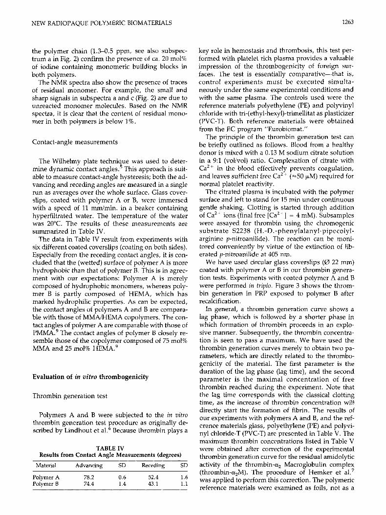
The Wilhelmy plate technique was used to deter- mine dynamic contact angle^.^ This approach is suit- able to measure contact-angle hysteresis; both the ad- vancing and receding angles are measured in a single run as averages over the whole surface. Glass cover- slips, coated with polymer A or B, were immersed with a speed of 11 mm/min. in a beaker containing hyperfiltrated water. The temperature of the water was 20°C. The results of these measurements are summarized in Table IV.
The data in Table IV result from experiments with six different coated coverslips (coating on both sides). Especially from the receding contact angles, it is con- cluded that the (wetted) surface of polymer A is more hydrophobic than that of polymer B. This is in agree- ment with our expectations: Polymer A is merely composed of hydrophobic monomers, whereas poly- mer B is partly composed of HEMA, which has marked hydrophilic properties. As can be expected, the contact angles of polymers A and B are compara- ble with those of MMNHEMA copolymers. The con- tact angles of polymer A are comparable with those of PMMA.9 The contact angles of polymer B closely re- semble those of the copolymer composed of 75 mol% MMA and 25 mol% HEMAa9
Evaluation of in vitro thrombogenicity
Thrombin generation test
Polymers A and B were subjected to the in vitro thrombin generation test procedure as originally de- scribed by Lindhout et a1.6 Because thrombin plays a
TABLE IV Results from Contact Angle Measurements (degrees)
Material Advancing SD Receding SD
Polymer A 78.2 0.6 52.4 1.6 Polymer B 74.4 1.4 43.1 1.1
key role in hemostasis and thrombosis, this test per- formed with platelet rich plasma provides a valuable impression of the thrombogenicity of foreign sur- faces. The test is essentially comparative-that is, control experiments must be executed simulta- neously under the same experimental conditions and with the same plasma. The controls used were the reference materials polyethylene (PE) and polyvinyl chloride with tri-(ethyl-hexy1)-trimellitat as plasticizer (PVC-T). Both reference materials were obtained from the EC program "Eurobiomat."
The principle of the thrombin generation test can be briefly outlined as follows. Blood from a healthy donor is mixed with a 0.13 M sodium citrate solution in a 9:l (volivol) ratio. Complexation of citrate with Ca2+ in the blood effectively prevents coagulation, and leaves sufficient free Ca2+ (=50 pM) required for normal platelet reactivity.
The citrated plasma is incubated with the polymer surface and left to stand for 15 min under continuous gentle shaking. Clotting is started through addition of Ca2+ ions (final free [Ca2+] = 4 mM). Subsamples were assayed for thrombin using the chromogenic substrate S2238 (H.-D.-phenylalanyl-pipecolyl- arginine p-nitroanilide). The reaction can be moni- tored conveniently by virtue of the extinction of lib- erated p-nitroanilide at 405 nm.
We have used circular glass coverslips (0 22 mm) coated with polymer A or B in our thrombin genera- tion tests. Experiments with coated polymer A and B were performed in triplo. Figure 3 shows the throm- bin generation in PRP exposed to polymer B after recalcification.
In general, a thrombin generation curve shows a lag phase, which is followed by a shorter phase in which formation of thrombin proceeds in an explo- sive manner. Subsequently, the thrombin concentra- tion is seen to pass a maximum. We have used the thrombin generation curves merely to obtain two pa- rameters, which are directly related to the thrombo- genicity of the material. The first parameter is the duration of the lag phase (lag time), and the second parameter is the maximal concentration of free thrombin reached during the experiment. Note that the lag time corresponds with the classical clotting time, as the increase of thrombin concentration will directly start the formation of fibrin. The results of our experiments with polymers A and B, and the ref- erence materials glass, polyethylene (PE) and polyvi- nyl chloride-T (PVC-T) are presented in Table V. The maximum thrombin concentrations listed in Table V were obtained after correction of the experimental thrombin generation curve for the residual amidolytic activity of the thrombin-or, Macroglobulin complex (thrombin-or,M). The procedure of Hemker et al.7 was applied to perform this correction. The polymeric reference materials were examined as foils, not as a

1264 KRUFT ET AL.
1 d(E) I ? A
- _ - . i I ~ .A * *-*, * ,--x
0.00 5.00 10.00 15.00 20.00
Time [Min]
I 250.00
200 00 1 B
Of0 5 0 0 1000 1500 2000 2500
Time [Min]
-50 00
Figure 3. (A) Experimental curve, i.e., d(E)/dt (arbitrary units; E = extinction) versus time. The residual amidolytic activity at the end of the experiment (time >15 min) is due to the thrombin-a,-macroglobulin complex. (B) Thrombin concentration as a function of time; a correction for the amidolytic activity of the thrombin a,-macroglobulin com- plex was performed according to the procedure of Hemker et al.7 U, polyethylene; X, polymer B (experiment in triplo); A = PVC-T.
coating on glass. In the case of PVC-T, we have ver- ified that the same lag time is found for the polymer as a film, and for the polymer as a coating on glass (see Table V).
In comparison with PE and glass (see Table V), polymers A and B are less thrombogenic. It is seen that polymer B is comparable with PVC-T in terms of
TABLE V Results of Thrombin Generation Tests for Coated Polymer A, Polymer 6, and Reference Materials
Material Lag Time (s) Max. Thromb. Conc. (nM)*
Glass 217 PE 335 PVC-T foil 587 PVC-T coated 583 Polymer At 392 k 14 Polymer Bt 553 ? 13
154 227
71 64
76 2 1 64 2 3
lag-phase duration. For polymer A, thrombin gener- ation proceeds faster than for polymer B. Comparing the maximum thrombin concentrations reached with polymers A, B, and PVC-T, it is seen that polymer B and PVC-T are highly comparable (max. [thrombin] = 70 nM). Note also that relative low max. [thrombin] L- 75 nM was found for polymer A.
Polymer B is thus less thrombogenic than polymer A. This may correlate with our finding that the sur- face of polymer B is more hydrophilic than that of polymer A (vide supra). Our data are reminiscent of other reports that state that a balance of hydropho- bicity and hydrophilicity of the surface is needed for good blood-compatibility features. 10-12
Adhesion of blood platelets to polymers A and B
Polymers A and B were incubated with citrated platelet rich plasma for 30 min at 37°C. Scanning elec- tron micrographs showed adhesion of platelets to the polymer A surfaces whereas virtually no adhesion was seen for polymer B. Figure 4 shows the morphol-
*Calculated for thrombin generation curves according to Hemker et al.7
tExperiments with coated polymer A and B were per- formed in triplo; the reported lag time and maximal throm- bin concentrations are averages of three experiments; the standard deviations are also given.
Figure 4. SEM micrographs of polymer A (coated on glass) after incubation with platelet rich plasma for 30 min at 37°C. (A) Overview. The length of the bar = 0.1 mm. (B) Detail showing the morphology of adhered platelets. For- mation of small pseudopods is noted. Bar = 10 bm.

NEW RADIOPAQUE POLYMERIC BIOMATERIALS 1265
ogy of platelets adhered to polymer A; Most of the surface is uncovered (see a in Fig. 4).
The corresponding detail (b) reveals that the few platelets extend small pseudopods-that is, a minor change in platelet morphology has occurred upon ad- sorption to polymer A. It is interesting to compare the results with the controls-platelets of the same plasma adhered to the reference materials PE and PVC-T. For PE, complete spreading of the platelets was found in the way that the entire surface was covered. Virtually no adhesion of platelets was found for PVC-T; in fact these SEM micrographs resemble those found for polymer B. It can be concluded that the surface of polymer B did not induce platelet acti- vation in this test. For polymer A, minor activation of adhered platelets was found.
X-ray visibility
An important additional question concerned the ra- diopacity: Are small objects made out of polymers A or B detectable using X-ray absorption imaging tech- niques that are routine in the clinic? To address this question, we have drawn fibers from polymers A and B (diameter ca. 0.3 mm). Figure 5 shows four fibers: a polymer A; b: polymer B; c: the terpolymer MMA/ HEMA/l (75/15/10 mol%); and d: the copolymer MMAlHEMA (80/20 mol%) as a control.
These fibers were glued on a paper sheet, which was subsequently submitted to fluoroscopy. X-ray absorption from the patient’s body was mimicked by a 15-cm-thick layer of Plexiglas. In this setup, the two fibers built of 20 mol% of 1 (polymers A and B) were clearly visible. A clearly reduced contrast was ob-
served for the polymer that contained only 10 mol% of 1. Visibility of these thin fibers virtually ensures that greater objects out of polymers A and B are easily detectable using routine imaging techniques. This feature, combined with our data on thrombogenicity, leads us to expect that our materials are particularly suitable for the manufacture of a new type of endo- vascular stents. This is especially the case for polymer B. It is known that metallic stents (easily visible with X-ray) frequently fail to prevent restenosis and/or acute thrombus formation after PTCA.
Two examples of routinely used metallic stents are shown in Figure 6, and illustrate the visibility under fluoroscopy after implant in patient coronary arteries. Panel A of Figure 6 shows a Johnson and Johnson stent, composed of 0.15-mm stainless-steel wires, in a coronary artery of a patient. Panel B in Figure 6 shows the Wiktor stent, made of 0.15-mm tantalum wires, in a coronary artery of a patient. Both stents are indicated by arrows. Obviously, visibility of tan- talum is superior to that of stainless-steel under X-ray.
Use of polymers A and B, or a whole range of anal- ogous polymeric materials, may provide us with a means to construct stents with combined X-ray visi- bility and improved hemocompatibility. Studies fo- cused on further improvement of the mechanical properties of polymers A and B, and analogous ma- terials, as well as on other biomedical applications, are currently in progress in this laboratory.
CONCLUSIONS In the present work we prepared and characterized
two novel polymeric materials (polymers A and B),
Figure 5. Drawn fibers from polymer A (a), polymer B (b), the terpolymer MMAiHEMAil (75/15/10 mol%) (c), and the copolymer MMA/HEMA (80/20 mol%) (d) as a control. (I) The four fibers a, b, c, and d as glued on a paper sheet. (11) The same four fibers submitted to fluoroscopy.

1266 KRUFT ET A t .
Heijnen for performing and interpreting the SEM experi- ments.
References
Figure 6. (A) X-ray photograph showing a Johnson and Johnson stent composed of 0.15-mm stainless-steel wires, in a coronary artery of a patient. The site of the stent is marked with an arrow. (B) Wiktor stent made of 0.15-mm tantalum wires, in a coronary artery of a patient. The site of this stent is marked by an arrow. Note the significantly better visibility of tantalum when compared with stainless steel.
which are built of 20 mol% of the acrylic monomer 1. Both materials are genuine polymers, as evidenced by gel permeation chromatography. This is important to note, as other workers have encountered problems in obtaining polymers when using other iodine con- taining acrylates. ‘p3
The new polymers were found to exhibit satisfac- tory low thrombogenicity in our in vifro test system. Both thrombin generation tests, and SEM studies of platelet adhesion led to this conclusion. These mate- rials were even visible as fibers with a diameter of ca. 0.3 mm using routine imaging X-ray techniques. It is foreseen that fibers of especially polymer B will be suitable for the manufacture of an all-polymeric en- dovascular stent.
The authors gratefully acknowledge Dr. Chris Reuteling- sperger for his helpful suggestions. They thank Viviane
1.
2.
3.
4.
5.
6 .
7.
8. 9.
10.
11.
12.
A. Jayakrishnan, B. Chithambara Thanoo, K. Rathi- nam, and M. Mohanty, ”Preparation and evaluation of radiopaque hydrogel microspheres based on PHEMAhothalamic acid and PHEMAhopanoic as par- ticulate emboli,” J. Biomed. Mater. Res., 24, 993-1004 (1990). A. Jayakrishnan and B. Chithambara Thanoo, ”Syn- thesis and polymerization of some iodine-containing monomers for biomedical applications,” J. Appl. Polym. Sci., 44, 743-748 (1992). D. Horak, M. Metalova, F. Svec, J. Drobnik, J. Kalal, M. Borovicka, A. A. Adamyan, 0. S. Voronkova, and K. Z . Gumargalieva, “Hydrogels in endovascular em- bolization. 111. Radiopaque spherical particles, their preparation and properties,” Biomaterials, 8, 142-145 (1987). D. F. Williams and R. Roaf, Implants in Surgery, WB Saunders, London, 1973, pp 132-134. H. S. van Damme, A. H. Hogt, and J. Feyen, ”Surface mobility and structural transitions of poly (n-alkyl methacrylates) probed by dynamic contact angle mea- surements,” I. Colloid Znterfuce Sci., 114, 167 (1986). T. Lindhout, D. Baruch, P. Schoen, J. Franssen, and H. C. Hemker, ”Thrombin generation and inactiva- tion in the presence of antithrombin I11 and heparin,” Biochemistry, 25, 5962-5970 (1986). H. C. Hemker, G. M. Willems, and S. A. Beguin, “A computer assisted method to obtain the prothrombin activation velocity in whole plasma independent of thrombin decay processes,” Thromb. Haemost., 56,
M. A. B. Kruft, unpublished results. A. H. Hogt, J. Dankert, and J. Feyen, “Adhesion of coagulase-negative staphylococci to methacrylate polymers and copolymers,” J. Biomed. Mater. Res., 20, 53S545 (1986). T. Sasaki, B. D. Ratner, and A. S. Hoffman, ”Radia- tion-induced cograft polymerization of Z-hydroxyeth- yl methacrylate and ethyl methacrylate onto silicone rubber films,” A.C.S. Symp. Ser., 31, 283-294 (1976). E. Nyilas, W. A. Morton, D. M. Ledermans, T. H. Chiu, and R. D. Cumming, “Interdependence of he- modynamic and surface parameters in thrombosis,” Trans. Am. SOC. Artif. Intern. Organs, 21, 55-69 (1975). C. K. Akers, I. Dardik, H. Dardik, and A. M. Wodka, “Computational methods comparing the surface properties of the inner walls of isolated human veins and synthetic biomaterials,” J. Colloid Interface Sci., 59, 461467 (1977).
9-17 (1986).
Received March 1, 1994 Accepted April 27, 1994