
Two-Link Failure Protection in WDM Mesh Networks with p-Cycles
30
Two-Link Failure Protection in WDM Mesh Networks with p-Cycles Taiming Feng a , Long Long b , Ahmed E. Kamal b , Lu Ruan a a Department of Computer Science, Iowa State University, Ames, IA 50011 b Department of Electrical and Computer Engineering, Iowa State University, Ames, IA 50011 Abstract In WDM networks, it is important to protect connections against link failures due to the high bandwidth provided by a fiber link. Although many p-cycle based schemes have been proposed for single-link failure protection, protection against two-link failures have not received much attention. In this paper, we propose p-cycle based protection schemes for two-link failures. We formulate an ILP model for the p- cycle design problem for static traffic. We also propose two protection schemes for dynamic traffic, namely SPPP (Shortest Path Pair Protection) and SFPP (Short Full Path Protection). Simulation results show that SFPP is more capacity efficient than SPPP under incremental traffic. Under dynamic traffic, SPPP has lower blocking than SFPP when the traffic load is low and has higher blocking than SFPP when the traffic load is high. Key words: WDM , Survivability , p-Cycle , Two-link Failure 1. Introduction Network survivability is an important requirement for WDM optical networks due to their ultra-high capacity. Various protection schemes have been developed for WDM networks. Ring-based protection schemes enable traffic recovery to be completed in 50-60 ms, but require at least 100% capacity redundancy. On the other hand, mesh-based protection schemes are much more capacity efficient, at- tributed to diverse traffic routing and protection capacity sharing among differ- ent connections. However, more complicated protection switching process leads to much longer recovery time. p-Cycle is a promising protection technique as it Email addresses: [email protected] (Taiming Feng), [email protected] (Long Long), [email protected] (Ahmed E. Kamal), [email protected] (Lu Ruan) Preprint submitted to Computer Networks April 29, 2010
Transcript of Two-Link Failure Protection in WDM Mesh Networks with p-Cycles

Two-Link Failure Protection in WDM Mesh Networks withp-Cycles
Taiming Fenga, Long Longb, Ahmed E. Kamalb, Lu Ruana
aDepartment of Computer Science, Iowa State University, Ames, IA 50011bDepartment of Electrical and Computer Engineering, Iowa State University, Ames, IA 50011
Abstract
In WDM networks, it is important to protect connections against link failures due tothe high bandwidth provided by a fiber link. Although many p-cycle based schemeshave been proposed for single-link failure protection, protection against two-linkfailures have not received much attention. In this paper, we propose p-cycle basedprotection schemes for two-link failures. We formulate an ILP model for the p-cycle design problem for static traffic. We also propose two protection schemes fordynamic traffic, namely SPPP (Shortest Path Pair Protection) and SFPP (Short FullPath Protection). Simulation results show that SFPP is more capacity efficient thanSPPP under incremental traffic. Under dynamic traffic, SPPP has lower blockingthan SFPP when the traffic load is low and has higher blocking than SFPP whenthe traffic load is high.
Key words:WDM , Survivability , p-Cycle , Two-link Failure
1. Introduction
Network survivability is an important requirement for WDM optical networksdue to their ultra-high capacity. Various protection schemes have been developedfor WDM networks. Ring-based protection schemes enable traffic recovery to becompleted in 50-60 ms, but require at least 100% capacity redundancy. On theother hand, mesh-based protection schemes are much more capacity efficient, at-tributed to diverse traffic routing and protection capacity sharing among differ-ent connections. However, more complicated protection switching process leadsto much longer recovery time. p-Cycle is a promising protection technique as it
Email addresses: [email protected] (Taiming Feng), [email protected](Long Long), [email protected] (Ahmed E. Kamal), [email protected] (Lu Ruan)
Preprint submitted to Computer Networks April 29, 2010

2
achieves the speed of ring with the efficiency of mesh [1], [2]. p-Cycles are es-tablished by configuring the spare capacity into pre-cross-connected cycles. Upona link failure, protection switching is performed at the two endnodes of the failedlink and other switching nodes will not be reconfigured. Therefore, traffic recov-ery is extremely fast. p-Cycle is also efficienct in protection since it protects bothon-cycle links and straddling links. As shown in Fig. 1, a-b-c-d-f-a is a p-Cycle.For the on-cycle link a-b, the p-Cycle provides one protection path a-f-d-c-b. Forthe straddling link a-c, the p-Cycle provides two protection paths: a-b-c and a-f-d-c. Thus, p-Cycle can protect one unit of working capacity on every on-cycle linkand protect two units of working capacity on every straddling link. Moreover, thep-Cycle has the property to provide protection for multiple failures. For example,if f-b and f-c both fail, f-a-b can provide protection for f-b and f-d-c can providethe protection for f-c.
a
e b
d c
f
p-Cycle:a-b-c-d-f-a
on-cycle links:
a-b, b-c, c-d, d-f, f-a
straddling links:
a-c, b-f, c-f
Figure 1: A p-Cycle Example
The concept of p-cycle was first proposed in [3] and subsequently many worksin literature study the p-cycle design problem for protecting against single-linkfailures. Most of these works assume the demands have been routed and seek tofind the optimal set of p-cycles to protect the given working capacity [3], [4], [5].The joint optimization of the working path routes and the p-cycles is studied in[6]. An extension of the basic p-cycle concept called Failure Independent Path-Protecting (FIPP) p-cycle is proposed in [7], which leads to more capacity efficientnetwork designs than link protecting p-cycle. Recently, the author of [8] introduceda new 1 + N protection scheme against single-link failures by combining networkcoding and p-cycles.
Although single-link failures are the most common failure scenarios, double-link failure can occur in some cases. First, after a link fails, a second link may failwhile the first link is being repaired. Second, two fiber links may be physically

3
routed together for some distance and a backhoe accident may lead to the failuresof both links [9]. Third, if an optical switch with two links connected to it fails, thenboth links fail. Double-link failure protection has been addressed in some works. In[10], a p-cycle based scheme for double-link failure protection is proposed wherep-cycles are reconfigured based on the remaining spare capacity after a link failureoccurs and the corresponding working paths are rerouted. This scheme cannotdeal with simultaneous two-link failures. In the scheme proposed in [9], two link-disjoint backup paths are computed for each link so that the network is two-linkfailure survivable. The similar scheme was also proposed in [11] and the problemwas formulated as an Integer Linear Program. The scheme is slow in recoverybecause the backup paths are configured after link failure occurs. In [12], a p-cycle based multi-QoP (quality of protection) framework with five QoP serviceclasses is proposed, where the platinum class is assured protection from all two-linkfailures. The protection for a platinum demand is achieved by routing it entirelyover straddling links. There are also some work addressing multiple-link failureprotection. The authors of [13] proposed algorithms to find k disjoint p-cycles toprotect each link such that the network is k link-failure survivable. The author of[14] extended his work in [8] to protect multiple-link failures by using networkcoding and p-cycles.
In this paper, we consider the problem of protecting connections against twosimultaneous link failures. Our basic idea is to use two p-cycles with link-disjointprotection segments to protect each working link. Since p-cycles are preconfiguredusing the spare capacity in the network, extremely fast recovery can be achieved.We formulate an ILP model for the p-cycle design problem for static traffic modelin which the set of connections to be established is given a priori. We propose twoprotection schemes for dynamic traffic. In the dynamic traffic model, connectionrequests arrive at the network one by one and the network knows nothing about thebandwidth requirement, source and destination node of incoming requests. Thus,primary and backup lightpaths need to be computed online according to the uti-lization of the current network resources. We also study the performance in in-cremental traffic which is a special case of dynamic traffic and the demand neverterminates once it is satisfied.
The rest of this paper is organized as follows. In Section 2, we present twotheorems about double-link failure protection. An ILP model for the p-cycle designproblem for static traffic is given in Section 3. In Section 4, we propose two double-link failure protection schemes for dynamic traffic. Numerical results are presentedin Section 5 and conclusions are given in Section 6.

4
2. Preliminaries
We use a directed graph G = (V, E) to represent a WDM optical network. Abidirectional communication link between nodes u and v are represented by twodirected edges u�v ∈ E and v�u ∈ E. Connections are unidirectional and eachconnection requires one unit of capacity (i.e., the capacity of a wavelength). We useunidirectional p-cycles to protect connections. A unidirectional p-cycle consumesone unit of capacity on each unidirectional on-cycle link; it can protect one unit ofworking capacity on any straddling link and any link in the opposite direction ofan on-cycle link.
A DB CGF E pc1pc2 Working Link: A->Dp-Cycle pc1: (A->F->G->D->C->B->A)p-Cycle pc2: (A->E->D->C->B->A)
Figure 2: Two-Link Failure Protection p-Cycles for Link A�D
In [13], two link-disjoint p-cycles are computed to protect a working linkagainst two link failures. However, we do not have to enforce the link-disjointrequirement on the two p-cycles in order to protect a link against two link failures.In fact, when a link e is protected by a p-cycle pc, only part of the p-cycle is usedfor protection. We name the part of pc that carries the traffic when e fails as the pro-tection segment for e on pc, which is denoted by pc(e). Fig. 2 shows two p-cyclespc1 and pc2, both of which can protect link A�D. pc1(A�D)=(A�F�G�D)is the protection segment for link A�D on pc1 and pc2(A�D)=(A�E�D) isthe protection segment for link A�D on pc2. Although pc1 and pc2 are not link-disjoint (they share links D�C, C�B, and B�A), they can still protect link A�Dagainst two link failures since pc1(A�D) and pc2(A�D) are link-disjoint.
The following theorem gives the sufficient condition for the traffic on a workinglink to be protected against any two-link failure.
Theorem 1. A working link A�B can be protected against any two-link failure ifthere exist two p-cycles pc1 and pc2 such that the following conditions are met.

5
1. pc1 can protect link A�B;2. pc2 can protect link A�B;3. pc1(A�B) is link-disjoint with pc2(A�B).
Proof The three conditions ensure that there are three link-disjoint paths from A toB: one is the direct link from A to B, the other two are pc1(A�B) and pc2(A�B).When any two links in the network fail, there must exist at least one path from Ato B that is intact. Therefore, link A�B is protected against any two-link failure.
According to Theorem 1, we can use two protection-segment-disjoint p-cyclesto protect a working link against two link failures. However, using two p-cycles toprotect each working link requires a large amount of protection capacity. To reducethe capacity requirement, we allow two working links to share the protection of acommon p-cycle. Let e1 and e2 be two working links. Let S1 and S2 be a pair ofprotection-segment-disjoint p-cycles for e1 and e2, respectively. If |S1 ∩ S2| = 1,then e1 and e2 share one p-cycle. If |S1 ∩ S2| = 2, then e1 and e2 are protected bythe same pair of p-cycles. When two links share one or two p-cycles, it is possiblethat the failure of these two links will leave one or both of them unprotected. Inthis case, we say the sharing is invalid. On the other hand, we say the sharing isvalid if the two links are still protected when both of them fail simultaneously. Inthe following, we present a theorem that gives the sufficient condition for a validsharing.
Theorem 2. Let e1 and e2 be two working links that share one or two p-cycles(i.e., S1 ∩ S2 6= ∅). The sharing is valid if the following conditions are met.
1. For link e1, there exists a p-cycle pc1 ∈ S1 such that e2 /∈ pc1(e1).2. For link e2, there exists a p-cycle pc2 ∈ S2 such that e1 /∈ pc2(e2);3. pc1(e1) is link-disjoint with pc2(e2) if pc1 = pc2.
Proof Upon a two-link failure, we consider the case that only one of e1 and e2
fails, say e1, so e2 is still working and only e1 needs to be protected. Based onTheorem 1, there must still exist one protection segment for e1 that is not affectedby another link failure, since e1 is protected by two link-disjoint segments. Thus,both e1 and e2 can survive regardless of protection sharing.
Thus, we only need to focus on the case where both e1 and e2 fail. Conditions1 and 2 ensure that both pc1(e1) and pc2(e2) are not affected by the failures. Ifpc1 6= pc2, then e1 and e2 are protected by pc1 and pc2, respectively. In this case,the sharing is valid. If pc1 = pc2, then pc1(e1) has to be link-disjoint with pc1(e2)described in condition 3. Otherwise, one unit protection capacity provided by a p-cycle is not enough to protect two failed link at a time. Thus, pc1(e1) and pc1(e2)have to be link-disjoint to validate the sharing.

6A Bpc1D C pc2E
F A Bpc1D C pc2E
FTwo Working Links: (A->B, C->D)p-Cycle pc2: (A->D->C->B->A)
p-Cycle pc1(dashed line): (A->D->F->C->B->E->A) p-Cycle pc1(dashed line): (A->E->B->C->F->D->A)(a) (b)Figure 3: (a). pc1, pc2 fail to protect e1, e2 simultaneously; (b). pc1, pc2 protect e1, e2 simultane-ously.
Fig. 3 shows two examples of p-cycle sharing. In the example shown in Fig.3(a), two working links e1=A�B and e2=C�D are protected by the same pairof p-cycles, pc1 and pc2, where both e1 and e2 are straddling links of pc1 andon-cycle links of pc2. That is, S1 = S2 = {pc1, pc2}. When both e1 and e2
fail, pc2 can protect neither of them since e2∈pc2(e1) and e1∈pc2(e2). pc1 can beused to protect either e1 or e2 but not both because pc1(e1)=(A�D�F�C�B)and pc1(e2)=(C�B�E�A�D) are not link-disjoint. Therefore, e1 and e2 can-not validly share the p-cycles pc1 and pc2. We now consider the example shownin Fig. 3(b), where everything is the same except that the direction of p-cycle pc1
is reversed. In this case, pc1(e1) = (A�E�B) does not contain e2, pc1(e2) =(C�F�D) does not contain e1, and pc1(e1) and pc1(e2) are link-disjoint. Ac-cording to Theorem 2, e1 and e2 can validly share pc1 and pc2.
3. An ILP Model for Static Traffic Protection
In this section, we present an ILP model for the following p-cycle designproblem: given a network G = (V, E), the working capacity dab on each link(a�b)∈E, and the maximum number of p-cycles needed, compute a set of p-cyclesto protect the working capacity against two-link failures such that the total capacityrequired by the p-cycles is minimized.
In the input parameters, P is the upper bound of the number of p-cycles neededand can be computed according to the static demands. Suppose the static demandsneed M links with one unit of capacity reserved on each link, a total of 2M p-cycles will be required in the worst case to protect any double-link failures since

7
each link requires two p-cycles. In the results obtained by solving an ILP, variablesepmn (∀(m�n)∈E) identify the configuration of those computed p-cycles. Given a
p-cycle pcp, if all the corresponding variables epmn equal 0, this p-cycle is not used
to protect any link in the solution.
Input Parameters:P the maximum no. of p-cycles in the solution.p p-cycle index where p ∈ {1, 2, . . . , P}.
dab integer, total amount of working capacity on link a�b.Variable Notations:
epmn binary variable, 1 if p-cycle p uses link m�n as an on-
cycle link.zpn binary variable, 1 if node n is on p-cycle p.
xpab k binary variable, 1 if p-cycle p protects the kth working
capacity on link a�b.f
p,(ab k)mn binary variable, 1 if p-cycle p protects the kth working
capacity on link a�b and the protection segment traverseslink m�n.
vp,(ab k)cd binary variable, 1 if p-cycle p protects the kth working
capacity on link a�b and the protection segment does notuse link c�d or d�c.
ABp,(ab k)cd l binary variable, it equals |vp,(ab k)
cd − vp,(cd l)ab |.
Cp,(ab k)cd l binary variable, used in the absolute value constraints for
ABp,(ab k)cd l .
Objective:Minimize
∑p
∑
(m,n)∈E
epmn
The objective function sums the total capacity used by all the active p-cycles.1) Capacity Constraints:
∑p
xpab k ≥ 2, ∀(a�b) ∈ E, ∀k ≤ dab; (1)
∑
k
xpab k ≤ 1, ∀p, ∀(a�b) ∈ E; (2)
Equation (1) ensures that each working unit on a link should be protected byat least two p-cycles. Equation (2) ensures that a unidirectional p-cycle can protectonly one unit capacity on a given link.
8
2) Cycle Constraints:∑
(m�n)∈E
epmn =
∑
(n�l)∈E
epnl = zp
n, ∀p, ∀n ∈ V ; (3)
epmn + ep
nm ≤ 1, ∀p, ∀(m�n) ∈ E; (4)
Equations (3) is the flow conservation constraint for any simple cycle by en-suring that the in-degree and out-degree of every on-cycle node is 1. Equation (4)ensures that each unidirectional p-cycle p cannot traverse the same link twice inboth directions.
3) Link Protection Constraints:
∑m
fp,(ab k)mn −
∑
l
fp,(ab k)nl =
xpab k if n = b
−xpab k if n = a
0 otherwise
(5)
∀p, ∀(a�b) ∈ E, ∀n ∈ V, ∀k ≤ dab;∑m
fp,(ab k)ma =
∑n
fp,(ab k)bn = 0, ∀p, ∀(a�b) ∈ E, ∀k ≤ dab; (6)
fp,(ab k)mn ≤ ep
mn, ∀(a�b), (m�n)∈E, (a�b)6=(m�n), ∀p, ∀k ≤ dab; (7)
Equation (5) and (6) are the flow conservation constraints for each protectionsegment provided by a p-cycle p to protect the kth working capacity on link a�b.In this case, a unit of protection flow should be reserved from node a to b using theon-cycle links of p. But there is no incoming flow of source node a and outgoingflow of b along the protection segment. Equation (7) ensures that any link (m�n)used by a protection segment should be an on-cycle link of the protection p-cycle.
4) Protection Segment Disjointness Constraints:
fp,(ab k)mn + f q,(ab k)
mn ≤ 1, (8)
fp,(ab k)mn + f q,(ab k)
nm ≤ 1, (9)
∀(a�b), (m�n)∈E, (a�b) 6= (m�n) or (n�m), ∀p, q, p6=q, ∀k ≤ dab;
Any link should be link-disjoint with its protection segment in any direction,which is guaranteed by Equation (8) and (9).

9
5) Absolute Value Constraints:
vp,(ab k)cd = (xp
ab k − fp,(ab k)cd − f
p,(ab k)dc ), (10)
∀(a�b), (c�d) ∈ E, (a�b) 6= (c�d), ∀p,∀k ≤ dab;
ABp,(ab k)cd l ≥ v
p,(ab k)cd − v
p,(cd l)ab , (11)
ABp,(ab k)cd l ≥ −(vp,(ab k)
cd − vp,(cd l)ab ), (12)
ABp,(ab k)cd l ≤ v
p,(ab k)cd − v
p,(cd l)ab + 2C
p,(ab k)cd l , (13)
ABp,(ab k)cd l ≤ −(vp,(ab k)
cd − vp,(cd l)ab ) + 2(1− C
p,(ab k)cd l ), (14)
∀(a�b), (c�d) ∈ E, (a�b) 6= (c�d), ∀p, ∀k ≤ dab, l ≤ dcd.
Equation (10) defines vp,(ab k)cd , which will be used for protection sharing be-
tween link ab k and cd l. The absolute value ABp,(ab k)cd l is defined by equations
(11) - (14). Eq. (11) and (12) make sure that the absolute value is always greaterand equal to 0. However, they are not enough. When both v variables equal eachother, the absolute value should be 0. But it can still be either 0 or 1. In order tomake it equal 0, we have to introduce a new binary variable, Cp,(ab k)
cd l . Eq. (13) and(14) ensure that when both v variables equal 0 or 1 at the same time, the absolutevalue AB can only be 0 by randomly choosing C as either 0 or 1. Meanwhile,equation (11) and (12) are not violated.
6) p-Cycle Sharing Constraints:
fp,(ab k)mn + fp,(cd l)
mn + vp,(ab k)cd + v
p,(cd l)ab
≤∑
p
vp,(ab k)cd +
∑p
vp,(cd l)ab +
∑p
ABp,(ab k)cd l + 1, (15)
∀(a�b),(c�d)∈E, (a�b)6=(c�d), ∀p, ∀(m�n)∈E, ∀{k, l}≤dab.
Constraint (15) ensures that all p-cycle sharing are valid based on Theorem 2.It takes the following three cases into the consideration when both link (a�b) and(c�d) fail simultaneously.
If∑
p ABp,(ab k)cd l ≥ 1, link (a�b) and (c�d) can be protected by two different
p-cycles, because there exist at least one p such that |vp,(ab k)cd − v
p,(cd l)ab | = 1.
Assume that vp,(ab k)cd = 1, v
p,(cd l)ab = 0, then p can be used to protect link (a�b)
without traversing link (c�d). Meanwhile, there must exist another p′ that canprotect link (c�d) without traversing link (a, b), since there are two link-disjointprotection segments for (c�d).
If∑
p ABp,(ab k)cd l = 0, both link (a�b) and (c�d) share the same two p-cycles.
There are two cases to be discussed as follows:

10
1) If∑
p vp,(ab k)cd +
∑p v
p,(cd l)ab = 4, both link (a�b) and (c, d) are straddling
links of the two protection p-cycles. In this case, one of the two p-cycles can protect(a�b) and the other one can protect (c�d) when both links fail.
2) If∑
p vp,(ab k)cd +
∑p v
p,(cd l)ab = 2, one of the protection p-cycles actually
traverses both links and cannot be used for protection anymore. Thus, only one p-cycle p can be used to protect them. In this case, we must have f
p,(ab k)mn +f
p,(cd l)mn +
vp,(ab k)cd + v
p,(cd l)ab ≤ 3 to ensure that the protection segment p(a�b) and p(c�d)
are link-disjoint.Constraint (15) combines all three cases together to ensure that all p-cycle shar-
ing are valid. Note that the condition∑
p vp,(ab k)cd +
∑p v
p,(cd l)ab ≥ 2 always holds.
Thus, if∑
p ABp,(ab k)cd l ≥ 1, the sharing is valid. There is no need to address the
remaining two cases and Eq. (15) should not be violated. If∑
p ABp,(ab k)cd l = 0,
Eq. (15) ensures that one of the last two cases will occur.Current objective is to minimize the spare capacity required by the p-cycles.
However, this objective could be easily modified to achieve different goals. Forinstance: 1. If the goal is to minimize the maximum total capacity (working andspare capacity) used on any link, we can introduce a new variable ζ and a newconstraint: ζ ≥ dmn +
∑epmn, ∀(m�n) ∈ E. In this newly added constraint, ζ
is the maximal aggregated amount of capacity reserved by working capacity andprotection p-cycles on every link. Accordingly, the new objective will be: Minimizeζ. 2. In the second case, if the total amount of capacity provided by each link(m�n) is upper bounded by a number, denoted by λmn, we can introduce a newconstraint: λmn ≥ dmn +
∑epmn, ∀(m�n) ∈ E to ensure that the total capacity
reserved on each link will not exceed the limit. Therefore, our ILP model can bemodified in a flexible fashion to adapt to various network scenarios with differentdesign goals.
4. Protection Schemes for Dynamic Traffic
In this section, we study the problem of two-link failure protection for dynamictraffic. We assume that the working path for a connection is given. The problem isto compute a set of p-cycles to protect the working path against any two-link failureso that the total capacity required by the p-cycles is minimized. We present twoheuristic algorithms for this problem. Both algorithms are designed to achieve ef-ficient protection by employing p-cycle sharing. The notations and some functionsused in the algorithms are explained in Table 1.

11
Table 1: Notations used in the algorithms
Notations Meaning
P The set of links used by the working path of agiven connection
pcp A p-cycle indexed by ppcp(e) the protection segment on pcp that actually protect
link eC The set of all the existing p-cycles in the networkC(e) The set of existing p-cycles that can protect link eCtemp The set of protection segments that protect a set
of linkscycle build(e, n) Construct n new cycles that can protect echeck share(pci, pcj , e) Check whether p-cycle pci and pcj can protect
link e simultaneously in Algorithm 1check disjoint(pci, e) Check whether an existing p-cycle pci can protect
a working link e in Algorithm 2check share2(e, e′, pci) Check whether link e and e′ can share the protec-
tion of pci validly in Algorithm 2
4.1. Shortest Path Pair Protection SchemeWe propose the Shortest Path Pair Protection (SPPP) scheme in this section.
Given the working path P of a connection, SPPP computes a set of p-cycles toprotect P as follows. For each link on P, we compute two p-cycles to protect thelink so that the two p-cycles are protection-segment-disjoint. Whenever possible,we reuse the p-cycles that have been previously provisioned to minimize the totalprotection capacity.
s d1 2 3 4
pc1 pc2 pc3 pc4
pc’1 pc’2 pc’4pc’3
Figure 4: p-Cycles pci, pc′i protect link i (i=1,2,3,4)
Fig. 4 illustrates how SPPP protects a working path from s to d that traverseslink 1 through link 4. For each link on the working path, SPPP computes two p-

12
cycles with link-disjoint protection segments to protect the link. As shown in thefigure, pci and pc′i are used to protect link i, for 1 ≤ i ≤ 4. To save capacity,we allow a p-cycle to be shared by different working links if sharing is allowedaccording to Theorem 2. For example, suppose link 3 can share pc2 with link 2,then pc3 = pc2 and only one new p-cycle (i.e., pc′3) needs to be created for link3; suppose link 4 can share pc1 with link 1 and can share pc′2 with link 2, andpc1(link4) is link-disjoint with pc′2(link4), then pc4 = pc1, pc′4 = pc′2, and nonew p-cycle needs to be created for link 4.
SPPP uses a boolean function check share(pc1, pc2, e) to check whether twop-cycles can be used to protect a working link e. The checking procedure consistsof three steps. First, it checks whether e can be protected by pc1 and has validsharing with other links also protected by pc1; Second, check whether e can beprotected by pc2 with valid sharing; Third, whether pc1(e) and pc2(e) are link-disjoint. check share(pc1, pc2, e) returns true if all three steps are passed. Therules are actually based on Theorem 1 and 2. Given a working link e, the set ofexisting p-cycles that can protect e is denoted by C(e). That is, C(e) contains allexisting p-cycles that have e as an on-cycle link or a straddling link. For each linke ∈ P, SPPP computes two p-cycles for e as follows:
We try to use as many existing p-cycles as possible to maximize the sharing.We first check whether there exist two p-cycles inC(e) such that they can be reusedto protect e. If so, no new p-cycle needs to be created for e. This check canbe done by using the check share function. If two p-cycles cannot be found inC(e), we try to reuse at least one p-cycle. By checking the protection conditionof a p-cycle, say pci, we need to construct the second p-cycle pcj for e such thatpci(e) and pcj(e) are link-disjoint. If check share(pci, pcj , e) returns true, thene is protected against double-link failure. Finally, if none of the p-cycles in Ccan be reused to protect e, then we construct two new p-cycles for e such that theprotection segments for e on these two p-cycles are link-disjoint.
The function cycle build(e, n) is used to construct new cycles where n is thenumber of newly constructed cycles. If n = 1, the function finds the shortest paththat is link-disjoint with e using Dijkstra’s algorithm and then combines the samelink e in the opposite direction to form a cycle, which can be used to protect e. Ifn = 2, we first use Bhandari’s algorithm [15] to obtain a pair of link-disjoint pathsbetween the two end nodes of e with minimum total length by temporarily markingit invalid. We can obtain two p-cycles for e by combining each path with e in thereverse direction. Clearly, these two p-cycles can provide link-disjoint protectionsegments for e.
The pseudo-code of the SPPP scheme is shown in Algorithm 1. The input isa working path P and the set of the existing p-cycles, the output is a new set C ofp-cycles that protect P. The algorithm computes two p-cycles for each link e ∈ P

13
Algorithm 1: SPPP SchemeInput: Working Path P, the set of existing p-cycles, COutput: A updated set Cfor ∀e ∈ P do1
flag=2;2
if ∃{pci, pcj}∈C(e) s.t. check share(pci, pcj , e)==true then3
flag=0;4
C(e) = C(e)− {pci, pcj};5
end6
else if7
(∃pci ∈ C(e))∧ (pcj = cycle build(e, 1))∧ (check share(pci, pcj , e))then
flag = 1;8
C(e) = C(e)− {pci};9
∀e′ 6= e that can be protected by pcj , C(e′) = C(e′)⋃{pcj};10
C = C⋃{pcj};11
end12
if flag==2 then13
construct pc1 and pc2 for e by running cycle build(e, 2);14
∀e′ 6= e that can be protected by pc1, C(e′) = C(e′)⋃{pc1};15
∀e′ 6= e that can be protected by pc2, C(e′) = C(e′)⋃{pc2};16
C = C⋃{pc1, pc2};17
end18
end19
in the for loop from line 1 to line 19. The first step of the procedure is executed byLines 3-6, in which we try to find a pair of existing p-cycles to protect a given linke. The second step is conducted by Lines 7-12, in which we reuse a p-cycle pci andconstruct a new one, pcj to provide protection. The final step is to construct twonew p-cycles such that their protection segments are link-disjoint, which is realizedby Lines 13-18. It is worth noting that each p-cycle can only protect a link once.Once a link e has been protected by a given p-cycle, say pci, this p-cycle is valid toprotect e any more in the future. This is the reason that in Lines 5 and 9, we needto remove the p-cycles that have been used to protect e from C(e).
We now analyze the time complexity of SPPP. First, we check the running timeof function check share(pci, pcj , e) is O(|E||V |2) because it needs to check eachworking link protected by pci to see if it can share pci with e, and the time of thechecking process is O(|V |2). For each e ∈ P, the algorithm computes two p-cycles

14
for e. The time of this computation is dominated by the computation in line 3. Weassume |C(e)| is upper bounded by a constant. Since line 3 is executed for eachedge in the working path P and the number of edges in P is upper bounded by |V |,the complexity of SPPP is O(|E||V |3).
The advantage of the SPPP scheme is that it can save plenty of protection ca-pacity by exploiting p-cycle sharing. However, SPPP always creates short p-cycles,which are less efficient than long p-cycles as shown in [16] since short p-cycles tendto have less straddling links. In the next, we present another protection scheme thatmakes use of long p-cycles for connection protection.
4.2. Shortest Full Path Protection SchemeIn this section, we present the Shortest Full Path Protection (SFPP) Scheme.
Given the working path P of a connection, SFPP computes a set of p-cycles toprotect P as follows. First, we compute one short p-cycle for each link on P. Next,we compute a long p-cycle that contains all links on P and is link-disjoint with theprotection segments of all the working links computed in the first step. Clearly,the long p-cycle can protect every link in P. Therefore, each working link is stillprotected by two p-cycles (one short and one long) with link-disjoint protectionsegments. Like SPPP, SFPP reuses existing p-cycles whenever possible to saveprotection capacity.
s d1 2 3 4
pc1 pc2 pc3 pc4
pc5
Figure 5: p-Cycle pci protects link i (i=1,2,3,4) and pc5 protects links 1,2,3, and 4.
Fig. 5 illustrates how SFPP protects a working path from s to d that traverseslink 1 through link 4. Four short p-cycles, pc1 to pc4, are first found to protect link1 to link 4. These short p-cycles can be shared by the working links. For example,if link 3 can share pc1 with link 1, then pc3 = pc1 and no new short p-cycle needsto be created for link 3. In the second step, we find a long p-cycle, labeled aspc5, to cover the entire working path. pc5 must be link-disjoint with the protectionsegments pc1(link1) to pc4(link4) to ensure that each working link is protectedby two protection-segment-disjoint p-cycles.
We now explain the details of SFPP. We first find one short p-cycle for everylink e on the working path P. During this process, existing p-cycles will be reused

15
if sharing is possible. Specifically, when we process link e, we first check whetherthere is a p-cycle in C(e) that can be reused to protect e. A p-cycle pci can bereused to protect e if 1) pci does not contain any edge e′ 6= e ∈ P, and 2) for everylink e′ 6= e ∈ P that is protected by pci, pci(e) and pci(e′) are link-disjoint. Thefirst condition is needed because if pci contains e′, then pc and the long p-cyclewill not be protection-segment-disjoint since they both contain e′. The secondcondition is needed for the following reason. When both e′ and e fail, the long p-cycle can protect neither of them since the protection segment of one link containsthe other link. So, both links have to be protected by pci. We define a functioncheck disjoint(pci, e) to check whether those two conditions given a link e andan existing p-cycle pci. It returns true if both conditions are satisfied.
If the function returns false, a new p-cycle should be constructed for e with therequirement that it does not contain any edge e′ 6= e in P. After each link e ∈ P hasbeen protected by a p-cycle, we construct a long p-cycle as follows. We first markall the links in P as invalid as well as all links on the protection segments (providedby the short p-cycles) of all the working links in P. We can simply substitute e inthe function cycle build(e, n) by P and then run cycle build(P, 1) to form a longp-cycle pcf by combining two link-disjoint paths. One, denoted by P′, starts fromthe source s to the destination d and the other one is P in the opposite direction.Hence, each link on the path P is protected against double-link failure.
However, constructing this new long p-cycle may destruct the validity of shar-ing between any link e ∈ P with any link e′ /∈ P if e and e′ share a shortp-cycle. We have to make sure that after the construction of pcf , every linke ∈ P is still protected and every p-cycle sharing is valid. We define a functioncheck share2(e, e′, pci) to perform the checking process. The function returnstrue if the sharing of a p-cycle pci by e and e′ is valid based on Theorem 2. If thefunction returns false, we have to reconstruct the long p-cycle pcf because it mustcontain link e′ (We will explain why in the next.) We could make the sharing validif the new p-cycle pcf does not contain e′. Hence, we need to temporarily removee′ from G before construct the new pcf . After all troublesome links are removed,we recompute a long p-cycle pcf . We then repeat the process of checking p-cyclesharing validity and computing the long p-cycle until no invalid p-cycle sharingcan be found.
We now explain why an invalid sharing of pci by e and e′ is caused by theinclusion of e′ in pcf . Let pc′f be the second p-cycle that protects e′. (The firstp-cycle that protects e′ is pci, which is shared by e.) In order for e and e′ to validlyshare pci, we have to make sure that when both links fail, at least one of pci andpc′f can protect e′ and at least one of pci and pcf can protect e. We know that atleast one of the protection segments pci(e′) and pc′f (e′) does not contain e sincethey must be link-disjoint. Therefore, there are three cases to consider as follows:

16
1. Neither pci(e′) nor pc′f (e′) contain e: Clearly, e′ can be protected by pc′fsince pc′f (e′) is not affected by the failure. In addition, one of pci and pcf
can protect e because pci(e) and pcf (e) are link-disjoint and therefore atleast one of them does not contain e′. So, e and e′ can validly share pci.
2. pci(e′) contains e and pc′f (e′) does not contain e: e and e′ can validly sharepci for the same reason given in the previous case.
3. pc′f (e′) contains e and pci(e′) does not contain e: e′ has to be protected bypci when both e and e′ fail. e can be protected by pcf if pcf (e) does notcontain e′. Therefore, the sharing is valid only if pcf (e) does not contain e′.
Algorithm 2: SFPP SchemeInput: Working path P, p-cycle set C, Ctemp = φ and flag=1Output: A updated set Cfor ∀e ∈ P do1
if ∃pci ∈ C(e) and check disjoint(pci, e)==true then2
link e is protected once;3
end4
else5
mark P\e invalid and obtain pci by running cycle build(e, 1);6
C = C⋃{pci};7
update C(e′) for all e′ that can be protected by pci;8
end9
Ctemp = Ctemp ∪ pci(e);10
end11
mark e ∈ P and e′ ∈ Ctemp invalid in G;12
construct pcf by running cycle build(P, 1);13
for ∀e ∈ P and e′ /∈ P that share pci ∈ C(e) do14
if check share2(e, e′, pci) == false then15
mark e′ invalid and flag=0;16
end17
end18
if flag == 0 then19
repeat Line 13;20
flag = 1 and goto Line 14;21
end22
Add pcf to C and C(e′) for all e′ ∈ E that can be protected by pcf ;23
As can be seen from the above three cases, if we know e and e′ cannot validly
17
share pc, then it must be the case that pcf contains e′. And we can turn the sharinginto a valid one by making sure that pcf does not contain e′.
The pseudo-code of the SFPP scheme is shown in Algorithm 2. The input is aworking path P and the set of existing p-cycles C, the output is the updated set Cof p-cycles. Set Ctemp stores the protection segments that are used to protect thelinks on P. The first loop from line 1-11 tries to find an existing p-cycle to protecteach link e ∈ P. If no existing p-cycle in C can protect a given e, then construct anew p-cycle. We need to make sure that certain capacity sharing conditions haveto be satisfied. The second part from line 12-13 is to construct the long p-cyclepcf for the whole path P. However, pcf may cause invalid sharing between anylink on P and the links not in P based on our previous analysis if it traverses anylink in Ctemp. Hence, we need to use function check share2 to check the validityof pcf . If the function returns false, we need to temporarily remove the link andreconstruct a new pcf repeatedly until a valid long p-cycle is found. This processis described by line 14-22. After we find a pcf that ensures all p-cycle sharing isvalid, we add it into set C and also update C(e′) for each edge e′ 6= e that can beprotected by pcf in line 23.
The time complexity of SFPP is dominated by the repeated construction pro-cess in lines 15-22. The complexity of function check share2(e, e′, pc) is O(|V |2),so the complexity of lines 15-18 is O(|V ||E||V |2) = O(|E||V |3). This block ofcode would be executed at most |E| times because at most |E| edges can be re-moved from G. Therefore, the complexity of SFPP is O(|E|2|V |3).
Since SFPP makes use of long p-cycles, when failures occur in the network,some rerouted working paths may pass through redundant nodes and links sinceprotection switching is done at the two endnodes of the failed link. This problemcan be solved using the algorithm given in [17], which removes the loop backs andrelease the redundant capacity by reconfiguring the restored paths.
5. Numerical Results
5.1. Metrics and Methodology
We use ILOG CPLEX 10.1.0 to implement the ILP on a computer with fourIntel Xeon 2.40GHz CPUs and 4G of memory. The ILP scheme provides the op-timal solution for static traffic demands. The simulations of SPPP and SFPP areimplemented on a computer with a Intel 3.0GHz CPU and 1.5G of memory. Wemeasure the performance of our schemes from following metrics:
• the protection redundancy: defined as the ratio of protection capacity toworking capacity.

18
• the reject ratio: defined as the ratio of the number of requests rejected to thenumber of requests received.
• the number of wavelength channels: one wavelength channel is defined asa wavelength on some link. For example, A 3-hop path uses 3 wavelengthchannels.
• the number of XC: this metric denotes the number of optical cross connectsthat need to be reconfigured upon a double-link failure.
When studying the performance of SPPP and SFPP, we first consider the in-cremental traffic, that is, a demand never terminates once it is satisfied. In thistraffic model, the capacity of the network link is set to infinity. Then we study theperformance of these two schemes in dynamic traffic model.
In both traffic models, a set of randomly generated connection requests areloaded to the network. For each connection request, the working path is routedalong the shortest path between the source and the destination. For dynamic traffic,the arrival of traffic follows Poisson distribution with λ connection requests persecond and the duration of the request is exponentially distributed with a mean of1/µ. The traffic load measured in erlangs is λ/µ.
5.2. ILP Results for Static TrafficA small test network with 6 nodes and 11 edges (shown in Fig. 6) is used to test
our ILP scheme. Table 2 shows the protection redundancy and the running time ofILP for different number of connections. Each data point is the average of ten testcases.
0
1
4
2
5
3
Figure 6: The 6-node 11-edge network.
The table shows that as the number of connections increases from 1 to 5, theprotection redundancy decreases from 592% to 302%. This is expected because p-cycle sharing can be better exploited when more connections exist in the network.On the other hand, the running time increases exponentially as the number of con-nections increases. We also use the SFPP and SPPP under the same scenarios and

19
Table 2: Redundancy and Computation time of ILP and heuristic algorithmsNumber of connections: 1 2 3 4 5ILP Run Times (s) 0.034 0.91 59.8 1304 11684.2Protection Redundancy(ILP): 592% 448% 373% 306% 302%Protection Redundancy(SPPP): 618% 546% 544% 534% 515%Protection Redundancy(SFPP): 600% 561% 535% 498% 502%
calculate their redundancy performance. As expected, and as shown in Table 2,SFPP and SPPP are not as efficient as the ILP under static traffic because they dealwith connection requests one by one and without considering the future incomingconnection requests.
When ILP is used to find the optimal protection strategy for static demands,there will be sufficient time between the planning and provisioning processes eventhe ILP has long run-time. Moreover, ILP can provide the baseline to evaluate theperformance of heuristic algorithms.
5.3. Comparison of SPPP and SFPP
We conduct simulations to compare the performance of SPPP and SFPP underincremental traffic and dynamic traffic. Three networks, the SMALLNET network, the COST239 network(Fig. 7) and the DISTRIBUTED network(Fig. 8)[18],which consists of 47 nodes and 98 links, are used in the simulations.
6
2
4
3
0
9
110
7
85
6
2
43
0
9
1
7
8
5
a) SMALLNET b) COST239
Figure 7: SMALLNET and COST239 Networks.
In the first set of simulations, we consider incremental traffic. The total numberof wavelength channels used by all the working paths and by all the p-cycles arerecorded for each simulation run.

20
6
2
4
30
9
1
10
78
5
1112
1314
1516
1718
1920
22
23
2425
2627
28
29 30
3132
33
34
3536
37
38
3940
414243
44
4546
21
Figure 8: Distributed Network.
0
5000
10000
15000
20000
25000
30000
35000
1000 2000 3000 4000 5000 6000 7000
Num
ber
of W
avel
engt
h C
hann
els
Use
d
Number of Connection Requests
Working PathSFPP SchemeSPPP Scheme
Figure 9: Wavelength usage of SPPP and SFPP in SMALLNET.
21
0
5000
10000
15000
20000
25000
30000
35000
1000 2000 3000 4000 5000 6000 7000
Num
ber
of W
avel
engt
h C
hann
els
Use
d
Number of Connection Requests
Working PathSFPP SchemeSPPP Scheme
Figure 10: Wavelength usage of SPPP and SFPP in COST239.
0
10000
20000
30000
40000
50000
60000
70000
80000
90000
1000 2000 3000 4000 5000 6000 7000
Num
ber
of W
avel
engt
h C
hann
els
Use
d
Number of Connection Requests
Working PathSFPP SchemeSPPP Scheme
Figure 11: Wavelength usage of SPPP and SFPP in DISTRIBUTED.

22
In Fig. 9, we show the performance of SPPP and SFPP under different traf-fic load in SMALLNET network. The results shows that SFPP uses less wave-length channels for protection than SPPP under all traffic loads. Specifically, SFPPachieves a 16.4%-18.3% reduction in wavelength usage over SPPP. The reason forSFPP to ourperform SPPP is that SFPP uses long p-cycles that have more strad-dling links so that higher protection efficiency can be achieved.
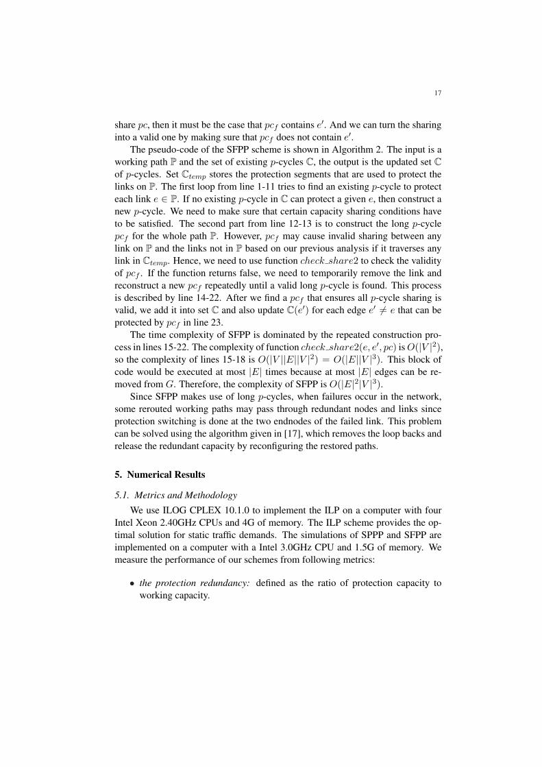
In Fig. 10, we show the performance of SPPP and SFPP in COST239 net-work. Again, SFPP uses less wavelength channels for protection than SPPP underall traffic loads. Specifically, SFPP achieves a 21.5%-24.5% reduction in wave-length usage over SPPP. The improvement of SFPP over SPPP is bigger than thatin SMALLNET network.
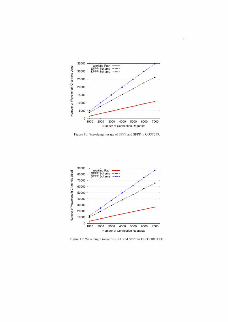
In Fig. 11, we show the performance of SPPP and SFPP in DISTRIBUTEDnetwork. Again, SFPP uses less wavelength channels for protection than SPPPunder all traffic loads. Specifically, SFPP achieves a 20.6%-24.2% reduction inwavelength usage over SPPP. We can also observe that the number of wavelengthchannels used is much higher than that used in SMALLNET and COST239 be-cause DISTRIBUTED is larger. With the increase of wavelength channels usedby the working path, the wavlength channels reserved by these p-Cycles will alsoincrease.
200
250
300
350
1000 2000 3000 4000 5000 6000 7000
Pro
tect
ion
Red
unda
ncy(
%)
Number of Connection Requests
SFPP Scheme
SPPP Scheme
Figure 12: Protection redundancy of SPPP and SFPP in SMALLNET.
Fig. 12, Fig. 13, and Fig. 14 compare the protection redundancy of SPPPand SFPP for SMALLNET, COST239 and DISTRIBUTED, respectively. Thesefigures show that the protection redundancy of SPPP and SFPP drop slightly as

23
200
250
300
350
1000 2000 3000 4000 5000 6000 7000
Pro
tect
ion
Red
unda
nce(
%)
Number of Connection Requests
SFPP Scheme
SPPP Scheme
Figure 13: Protection redundancy of SPPP and SFPP in COST239.
200
250
300
350
1000 2000 3000 4000 5000 6000 7000
Pro
tect
ion
Red
unda
nce(
%)
Number of Connection Requests
SFPP Scheme
SPPP Scheme
Figure 14: Protection redundancy of SPPP and SFPP in DISTRIBUTED.

24
the number of connections increases, which is consistent with the ILP results. Theredundancy of SFPP is much lower than that of SPPP. For SMALLNET, SFPPachieves 16.4%-18.3% reduction in redundancy over SPPP; For COST239, SFPPachieves 23.0% -24.5% reduction in redundancy over SPPP; For DISTRIBUTED,SFPP achieves 23% -24% reduction in redundancy over SPPP.
As shown in Table 3, we also study the efficiency of p-Cycles constructed bySFPP and SPPP under incremental traffic in three different networks. The p-Cycleefficiency of p-Cycle pci is defined as the ratio of working wavelength channelsprotected by pci over the wavelength channels reserved on p-Cycle pci. SFPP hasbetter efficiency performance than SPPP because SFPP tends to use longer p-cyclesthat can protect more straddling links. Thus, each p-cycle has higher capacityefficiency in average and this also explains why SFPP has lower redundancy.
Table 3: Comparison of p-Cycle EfficiencyNetworks SMALLNET COST239 DISTRIBUTEDSFPP Efficiency 0.75 0.78 0.71SPPP Efficiency 0.65 0.63 0.6
In the second set of simulations, we consider dynamic traffic. Each simulationhas 10 rounds and 5000 randomly generated connection requests are loaded to thenetwork in each round and the average reject ratio is recorded. The capacity of thenetwork link is set to 10 wavelengths.
In Fig 15, we compare the reject ratio of SFPP and SPPP under different trafficloads (in erlangs) in SMALLNET network. The results show that SFPP performsworse than SPPP when traffic load is low. This can be explained as follows. Whenthe traffic load is low, there is not enough connections to fully utilize the protectioncapacity provided by the long p-cycles. We also observe that the long p-cycles canbe fully utilized and they can provide more efficient protection than those p-cyclescreated by SPPP when the traffic load becomes high. According to our simulation,SFPP performs better than SPPP when traffic load is above 32 erlangs. However,the reject ratio is high and it is not practical.
In Fig 16, we compare the reject ratio of SFPP and SPPP under different trafficloads in COST239 network. Again, the results show that SFPP performs worsethan SPPP under low traffic loads. Similarly, SFPP will perform better than SPPPwhen the traffic load is above 30 erlangs.
In Fig 17, we compare the reject ratio of SFPP and SPPP under different trafficloads in DISTRIBUTED network. Again, the results show that SPPP performsmuch better than SFPP under low traffic loads. Which also shows that our SPPPhas good scalability performance.

25
0
0.01
0.02
0.03
0.04
0.05
0.06
0.07
1 2 3 4 5 6 7 8
Rej
ect R
atio
Traffic Load (Erlang)
SFPP Scheme
SPPP Scheme
Figure 15: Reject ratio of SPPP and SFPP in SMALLNET.
0
0.005
0.01
0.015
0.02
0.025
0.03
0.035
0.04
1 2 3 4 5 6 7 8 9
Rej
ect R
atio
Traffic Load (Erlang)
SFPP Scheme
SPPP Scheme
Figure 16: Reject ratio of SPPP and SFPP in COST239.

26
0
0.02
0.04
0.06
0.08
0.1
1 2 3 4 5 6 7
Rej
ect R
atio
Traffic Load (Erlang)
SFPP Scheme
SPPP Scheme
Figure 17: Reject ratio of SPPP and SFPP in DISTRIBUTED.
We also observe that the reject ratio is 0 in all of these three networks whenthere is no protection provided.
In Table 4, we compare the average computation time for a single demand us-ing SPPP and SFPP in two test networks. As the table shows, it only takes SPPP1.55 milliseconds on average to compute the p-Cycles for a demand in SMALL-NET. Meanwhile, SPPP runs faster than SFPP in both networks which correspondswell with previous time complexity analysis. SFPP just needs 2.45 milliseconds tocompute the p-Cycle in COST239. Thus, the proposed schemes are suitable fordynamic demands. Both algorithms need more run time in DISTRIBUTED, whichis expected because the DISTRIBUTED network has much more edges and nodes.
Table 4: Average Computation Time(milliseconds): 10 rounds, 5000 demands in each roundNetworks SMALLNET COST239 DISTRIBUTEDSPPP 1.55 1.9 39.86SFPP 2.1 2.45 69.56
5.4. Comparison of SPPP and the Algorithms in [9]
We compare SPPP with the three approaches–Method I, Method II, and MADPA–proposed in [9] as shown in Table 5. The network topology used is the 20-node32-link ARPANET network. Protection ratio is the percentage of double-link fail-ures that can be protected. Protection redundancy is the ratio of the total protection

27
Table 5: Comparison of Algorithms in ARPANETAlgorithm I II MADPA SPPPProtection ratio 100% 100% 98.8% 100%Protection redundancy 200% 200% 200% 259%XCmax with signaling 26 18 N/A 6XCavg with signaling 9.34 8.64 N/A 4.4XCmax w/o signaling N/A N/A 24 4XCavg w/o signaling N/A N/A 7.3 4
capacity to the total working capacity. XCmax and XCavg denote the worst-caseand average number of optical cross connects that need to be configured upon adouble-link failure. In [9], the authors assume the working capacity reserved oneach link is one unit such that the schemes proposed in the paper require fixedprotection capacity on each link, which equals 200%.
When a link fails, Methods I and II require that all nodes in the network are in-formed of the failure through signaling. However, this is not required for MADPA.SPPP can operate with or without signaling of the failure event. If, upon a link fail-ure, the traffic on the link is sent on both p-cycles simultaneously, then signaling isnot required. In this case, a total of 4 cross connections are needed to recover fromany double-link failure because the two endnodes of each failed link need config-ure their cross connects to direct the traffic onto the p-cycles. On the other hand, ifonly one p-cycle is used to restore the traffic upon a link failure, then signaling offailure is required and a total of 6 cross connections are needed to recover from adouble-link failure in the worst case.
The worst case occurs when the second failure affects the p-cycle used to pro-tect the first failure. In this case, when the first link fails, both endnodes configuretheir cross connects to direct the traffic onto the first p-cycle for this link. When thesecond link fails, the endnodes of the link configure their cross connects to directthe traffic onto one of the two p-cycles that is not affected by the first link failure.After the endnodes of the first failed link learn that the second failure affects thep-cycle being used, they reconfigure their cross connects to direct the traffic ontothe second p-cycle for this link. Thus, a total of 6 cross connections are needed.
The results in Table 5 show that while SPPP has higher protection redundancythan the other three methods, the number of cross connections required is muchless. Since p-cycles are pre-configured, SPPP requires only the endnodes of thefailed links to configure their cross connects. On the other hand, cross connectshave to be configured by every node along the protection path in the other threemethods. Thus, SPPP is much faster in restoration than the other methods. Basi-

28
cally, SPPP trades off protection redundancy for restoration speed. Compared withthe other methods, SPPP’s gain in restoration speed is much larger than its loss inprotection redundancy.
6. Conclusions
In this paper, we consider the problem of protecting connections against two-link failures. The basic idea is to protect each working link with two p-cycles withlink-disjoint protection segments. We present an ILP model to compute the opti-mal set of p-cycles for protecting a set of static demands. The ILP can providethe optimal solution for static demands and provide a baseline for evaluating theperformance of heuristic algorithms. Realizing that ILP is not suitable for onlineprovisioning process, we also propose two protection schemes – SPPP and SFPP– for dynamic demands. The numerical results show that SFPP is more capacityefficient than SPPP under incremental traffic. Under dynamic traffic, SPPP haslower blocking than SFPP in most practical cases. In addition to the time com-plexity analysis, we run simulations to show that the average computation timefor a single demand is at the milisecond-level. The time complexity analysis alsoshows the good scalability of our proposed SFPP and SPPP schemes. Comparedwith the algorithms proposed in [9], SPPP trades off protection redundancy for fastrestoration speed. In the future, we plan to develop heuristic algorithms to solvethe static traffic provisioning problem and design more efficient algorithms for dy-namic traffic in terms of running time and protection redundancy. We will alsoconsider multiple-link failure protection.
Acknowledgments
This work is supported by NSF ANI-0237592 and CNS-0626741.
References
[1] R. Yadav, R. S. Yadav, H. M. Singh, A review of survivable transport net-works based on p-cycles, in: International Journal of Computer Sciences andEngineering Systems, Vol. 1, 2007.
[2] W. Grover, D. Stamatelakis, Bridging the ring-mesh dichotomy with p-cycles,in: Proc. of DRCN Workshop, 2000.
[3] W. Grover, D. Stamatelakis, Cycle-oriented distributed preconfiguration:Ring-like speed with mesh-like capacity for self-planning network restora-tion, in: Proc. IEEE ICC’98, 1998, pp. pages 537–543.

29
[4] D. Schupke, C. Gruber, A. Autenrieth, Optimal configuration of p-cycles inwdm networks, in: Proc. of IEEE ICC, 2002.
[5] B. Wu, K. L. Yeung, S. Xu, Ilp formulation for p-cycle construction based onflow conservation, in: proceedings of the IEEE GLOBECOM, 2007.
[6] W. Grover, J. Doucette, Advances in optical network design with p-cycles:Joint optimization and preselection of candidate p-cycles, in: Proc. of IEELEOS Summer Topical Meeting, 2002.
[7] W. D. Grover, A. Kodian, Failure-independent path protection with p-cycles:Efficient, fast and simple protection for transparent optical networks, in: pro-ceedings of the ICTON, 2005, pp. 363–369.
[8] A. E. Kamal, 1+n network protection for mesh networks: Network coding-based protection using p-cycles, in: IEEE/ACM Transactions on Networking,Vol. 18, 2010, pp. 67–80.
[9] H. Choi, S. Subramaniam, H.-A. Choi, Loopback recovery from double-linkfailures in optical mesh networks, in: IEEE/ACM TRANSACTIONS ONNETWORKING, Vol. 12, 2004, pp. 1119–1130.
[10] D. Schupke, Multiple failure survivability in wdm networks with p-cycles, in:Proceedings of the International Symposium on Circuits and Systems, 2003.
[11] W. He, M. Sridharan, A. K. Somani, Capacity optimization for survivingdouble-link failures in mesh-restorable optical networks, Photonic NetworkCommunications 9 (1) (2005) 99–111.
[12] A. Kodian, W. D. Grover, Multiple-quality of protection classes includingdual-failure survivable services in p-cycle networks, in: proceedings of theBroadnets, 2005, pp. 231–240.
[13] H. Wang, H. T. Mouftah, P-cycles in multi-failure network survivability, in:Proceedings of International Conference on Transparent Optical Networks,2005.
[14] A. E. Kamal, 1+n protection against multiple faults in mesh networks, in:proceedings of the IEEE International Conference on Communications (ICC),2007.
[15] R. Bhandari, Survivable networks, algorithms for diverse routing, KluwerAcademic Publishers, Norwell, MA, USA, 1999.

30
[16] T. Feng, L. Ruan, W. Zhang, Intelligent p-cycle protection for multicast ses-sions in wdm networks, in: proceedings of the IEEE International Conferenceon Communications (ICC), 2008.
[17] R. Asthana, Y. Singh, Second phase reconfiguration of restored path for re-moval of loop back in p-cycle protection, in: Communications Letters, IEEE,Vol. 11, 2007, pp. 201–203.
[18] P. Baran, On distributed communications networks, in: IEEE Trans. Com-mun.,, Vol. COM-12, 1964, pp. 1–9.