Twin Low-cost Infrared Range Finders for Detecting Obstacles Using · PDF file ·...
4
Twin Low-cost Infrared Range Finders for Detecting Obstacles Using in Mobile Platforms Saman Kumpakeaw Abstract— The new approach to eliminate blind zone of an infrared range finder is introduced. Infrared sensors have normally limitations of each individual sensor type in terms of detection range and a wider range measurement of this sensor type costs certainly intensive. The idea to use multiple infrared sensors simultaneously, a short range and a long range one, is proposed to overcome this problem. This has been inspired by eyeglasses solutions to presbyopia, which have two lenses, one for near sight and one for seeing distant objects. Multiple sensors concept is used to span wider measuring range, even the cost remains low-budget, so that it can be used in educational research properly. The combination of a short range and a long range measurement can detect obstacles and measure distance continuously from distant (500 cm) to near field (20 cm) around it. Mobile platform in educational institutes can take these advantages for navigations and localization in indoor environments and also for obstacle avoidances. I. INTRODUCTION The discontinuous sight of presbyopia can be aided with eyeglasses that have two lenses, one for near sight and one for seeing distant objects. The most distance measuring sensors confront also the discontinuity according to their physical characteristic limitations. This results blind zone for detecting obstabcles in mobile robots and causes problems by navigations and avoidances in indoor environments. With the concept of eyeglasses for presbyopia, the multi-stage and multiple range finders are concerned in this approach to construct a low-cost, wide range, and continuous obstacle avoidance system for mobile platforms. A. Inspiration from eyeglasses for presbyopia Presbyopia is a vision disorder provoked by the aging eye condition. The helping aid are usually eyeglasses for presbyopia (Fig. 1), which have higher focusing power in the lower part of the lens. This allows reading ability through the lower part of the lens and see distant objects through the upper part of the lens clearly. In engineering research fields related with presbyopia, there are many approaches proposed in concept of artificial accommodation system to improve eyesight for presbyopia, mostly using thermoelectric or inductive elements implanted in the eyes to adjust prescription automatically [1], [2]. There are also a development for eyeglasses, which can adjust focus using EMG signal from presbyopia (mimic from face) [3] or detecting eye gaze movement to adjust focus automatically [4]. S. Kumpakeaw is with Department of Electronics Engineering Tech- nology, College of Industrial Technology, King Mongkut’s University of Technogloy North Bangkok, 10800 Bangsue, Bangkok, Thailand [email protected] Fig. 1. eyeglasses for presbyopia (source : Internet) TABLE I RANGE MEASUREMENT OF INFRARED SENSORS IR sensor type Distance measuring range output type GP2Y0A710K0F 100-550 cm analog (voltage) GP2Y0A02YK 20-150 cm analog (voltage) The aim for those researches is to make a continuous focusing for eye vision. The same problems that occur by presbyopia can be compared to range/ distance measurement sensors, which have limitation of sensing ranges. Although it is not impossible to produce a wide-range measurement sensor to cover all distances, but it costs intensive, so that the better solution is to deploy the multi-range sensors. B. Limitation of Range Finder in Mobile Robot Purposes for using infrared sensor in mobile robot is mainly because of low-cost and acceptable measurement in indoor environment. The most used infrared range finders in educational research and lectural are from the manu- facturer SHARP [5], [6], [7], [8], [9]. They are used in experimental platform to build maps for SLAM system and to avoid obstacles by navigations. Those researches use infrared sensors as fixed, not-turnable range sensors to detect and measure distance. The disadvantages of low-cost infrared sensors involve limited sensing accuracy, range, and computing abilities. II. INFRARED RANGE FINDER The characteristics of infrared range finder from SHARP are explained shortly. Some problems issues e.g. sensor limitations have to be known and in this way, the sensor deployment can be properly adapted in the later measurement system. A. Range Limitation The infrared range finder GP2Y0A02YK and GP2Y0A710K0F have limited range measurement as 978-1-4673-2126-6/12/$31.00 © 2012 IEEE
Transcript of Twin Low-cost Infrared Range Finders for Detecting Obstacles Using · PDF file ·...
Twin Low-cost Infrared Range Finders for Detecting Obstacles Using inMobile Platforms
Saman Kumpakeaw
Abstract— The new approach to eliminate blind zone ofan infrared range finder is introduced. Infrared sensors havenormally limitations of each individual sensor type in terms ofdetection range and a wider range measurement of this sensortype costs certainly intensive. The idea to use multiple infraredsensors simultaneously, a short range and a long range one,is proposed to overcome this problem. This has been inspiredby eyeglasses solutions to presbyopia, which have two lenses,one for near sight and one for seeing distant objects. Multiplesensors concept is used to span wider measuring range, even thecost remains low-budget, so that it can be used in educationalresearch properly. The combination of a short range and along range measurement can detect obstacles and measuredistance continuously from distant (500 cm) to near field (20cm) around it. Mobile platform in educational institutes cantake these advantages for navigations and localization in indoorenvironments and also for obstacle avoidances.
I. INTRODUCTION
The discontinuous sight of presbyopia can be aided witheyeglasses that have two lenses, one for near sight andone for seeing distant objects. The most distance measuringsensors confront also the discontinuity according to theirphysical characteristic limitations. This results blind zone fordetecting obstabcles in mobile robots and causes problemsby navigations and avoidances in indoor environments. Withthe concept of eyeglasses for presbyopia, the multi-stageand multiple range finders are concerned in this approachto construct a low-cost, wide range, and continuous obstacleavoidance system for mobile platforms.
A. Inspiration from eyeglasses for presbyopia
Presbyopia is a vision disorder provoked by the agingeye condition. The helping aid are usually eyeglasses forpresbyopia (Fig. 1), which have higher focusing power in thelower part of the lens. This allows reading ability throughthe lower part of the lens and see distant objects through theupper part of the lens clearly.
In engineering research fields related with presbyopia,there are many approaches proposed in concept of artificialaccommodation system to improve eyesight for presbyopia,mostly using thermoelectric or inductive elements implantedin the eyes to adjust prescription automatically [1], [2].There are also a development for eyeglasses, which canadjust focus using EMG signal from presbyopia (mimic fromface) [3] or detecting eye gaze movement to adjust focusautomatically [4].
S. Kumpakeaw is with Department of Electronics Engineering Tech-nology, College of Industrial Technology, King Mongkut’s Universityof Technogloy North Bangkok, 10800 Bangsue, Bangkok, [email protected]
Fig. 1. eyeglasses for presbyopia (source : Internet)
TABLE IRANGE MEASUREMENT OF INFRARED SENSORS
IR sensor type Distance measuring range output typeGP2Y0A710K0F 100-550 cm analog (voltage)GP2Y0A02YK 20-150 cm analog (voltage)
The aim for those researches is to make a continuousfocusing for eye vision. The same problems that occur bypresbyopia can be compared to range/ distance measurementsensors, which have limitation of sensing ranges. Althoughit is not impossible to produce a wide-range measurementsensor to cover all distances, but it costs intensive, so thatthe better solution is to deploy the multi-range sensors.
B. Limitation of Range Finder in Mobile Robot
Purposes for using infrared sensor in mobile robot ismainly because of low-cost and acceptable measurement inindoor environment. The most used infrared range findersin educational research and lectural are from the manu-facturer SHARP [5], [6], [7], [8], [9]. They are used inexperimental platform to build maps for SLAM systemand to avoid obstacles by navigations. Those researchesuse infrared sensors as fixed, not-turnable range sensors todetect and measure distance. The disadvantages of low-costinfrared sensors involve limited sensing accuracy, range, andcomputing abilities.
II. INFRARED RANGE FINDERThe characteristics of infrared range finder from SHARP
are explained shortly. Some problems issues e.g. sensorlimitations have to be known and in this way, the sensordeployment can be properly adapted in the later measurementsystem.
A. Range Limitation
The infrared range finder GP2Y0A02YK andGP2Y0A710K0F have limited range measurement as
978-1-4673-2126-6/12/$31.00 © 2012 IEEE
shown in Table I1. The GP2Y0A710K0F is concerned touse as a long range finder to detect obstacles in remotezone from 100-550 cm. In the distance shorter than 100 cm,there have to use another range finder to assure the obstacledetection in this zone. The GP2Y0A02YK is deployed tomeasure the distance between 20 cm and 150 cm. There isa overlapping zone between 100 cm and 150 cm.
Because the output measurement is done in analog, ithas to convert the measured output voltage to digital value,so that the programm in microcontroller can calculate thereal distances. The microcontroller board Arduino [12] has aanalog-to-digital conversion function with 10-bit resolution(210 resolutions) for the voltage range of 5V. The calculationfor conversion is then:
outputdigital = outputanalog ∗ (5V/210)= outputanalog ∗ (5/1024) (1)
B. Nonlinearity
The relation between the output voltage from sensorsand measured distances are unfortunately nonlinear. Fig 2shows the nonlinearity of infrared sensors GP2Y0A02 (left)and GP2Y0A710 (right) from SHARP. The most usefuloutput ranges according to datasheet are about 0.45-2.5V for GP2Y0A02 and about 1.4-2.5 V for GP2Y0A710.Others output values from graph change rapidly, so that themeasurement errors can be occured.
Fig. 2. Nonliearity of SHARP infrared range finders GP2Y0A02 (left) andGP2Y0A710 (right)
III. IMPLEMENTATION FOR OBSTACLEDETECTION USING INFRARED SENSORS
The aim of this approach is to develop a low-cost sen-sor prototype to detect obstacles and to build environmentmaps for mobile robot in indoor environment. The prototypemodel is shown in Fig. 3. Because the measurement withinfrared light can be disturbed by natural light, therefore theconditions for testing these sensors are limited in a roomwith the dimension of 5x5 meters. With the limitation ofdata transfer from microcontroller via serial communication,the indoor environments have to be static.
The twin sensors are mounted on a servo motor which canturn 180 degree. The assembled device is installed in the topmiddle of a mobile platform, which has a circumstance of30 cm. The short range infrared sensor can detect rangesbetween 20-150 cm and the long range measurement is
1due to datasheet [10], [11]
limited from 100 cm to 500 cm. There is a safety zonefor about 5 cm from platform body, before the platformhits obstacles and mechanical switches around platform areactivated as the last safety.
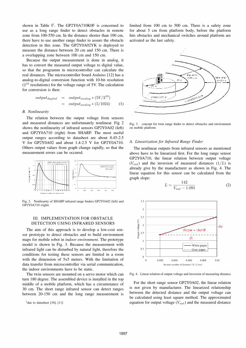
Fig. 3. concept for twin range finder to detect obstacles and environmenton mobile platform
A. Linearization for Infrared Range Finder
The nonlinear outputs from infrared sensors as mentionedabove have to be linearized first. For the long range sensorGP2Y0A710, the linear relation between output voltage(Vout) and the inversion of measured distances (1/L) isalready give by the manufacturer as shown in Fig. 4. Thelinear equation for this sensor can be calculated from thegraph slope:
L =142
Vout − 1.091(2)
Fig. 4. Linear relation of output voltage and inversion of measuring distance
For the short range sensor GP2Y0A02, the linear relationis not given by manufacturer. The linearized relationshipbetween the detected distance and the output voltage canbe calculated using least square method. The approximatedequation for output voltage (Vout) and the measured distance
(L) is in exponential form.
L = 65 ∗ (Vout)−1.10 (3)
B. Scan direction
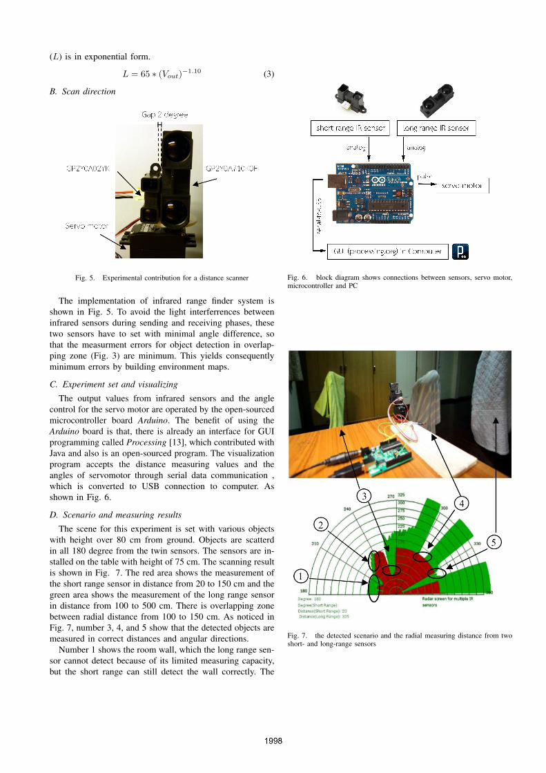
Fig. 5. Experimental contribution for a distance scanner
The implementation of infrared range finder system isshown in Fig. 5. To avoid the light interferrences betweeninfrared sensors during sending and receiving phases, thesetwo sensors have to set with minimal angle difference, sothat the measurment errors for object detection in overlap-ping zone (Fig. 3) are minimum. This yields consequentlyminimum errors by building environment maps.
C. Experiment set and visualizing
The output values from infrared sensors and the anglecontrol for the servo motor are operated by the open-sourcedmicrocontroller board Arduino. The benefit of using theArduino board is that, there is already an interface for GUIprogramming called Processing [13], which contributed withJava and also is an open-sourced program. The visualizationprogram accepts the distance measuring values and theangles of servomotor through serial data communication ,which is converted to USB connection to computer. Asshown in Fig. 6.
D. Scenario and measuring results
The scene for this experiment is set with various objectswith height over 80 cm from ground. Objects are scatterdin all 180 degree from the twin sensors. The sensors are in-stalled on the table with height of 75 cm. The scanning resultis shown in Fig. 7. The red area shows the measurement ofthe short range sensor in distance from 20 to 150 cm and thegreen area shows the measurement of the long range sensorin distance from 100 to 500 cm. There is overlapping zonebetween radial distance from 100 to 150 cm. As noticed inFig. 7, number 3, 4, and 5 show that the detected objects aremeasured in correct distances and angular directions.
Number 1 shows the room wall, which the long range sen-sor cannot detect because of its limited measuring capacity,but the short range can still detect the wall correctly. The
Fig. 6. block diagram shows connections between sensors, servo motor,microcontroller and PC
Fig. 7. the detected scenario and the radial measuring distance from twoshort- and long-range sensors

object in number 2 can be detected from both sensors but itshows that there is a measuring error because of the differentangle between two sensors.
IV. CONCLUSIONS AND FUTURE WORKS
A. Conclusions
This approach method for detecting obstacles with doubleinfrared range finders can assure the obstacle detectionin wider ranges, in which each minimum and maximumrange of each sensor cannot do. The method is inspiredfrom eyeglasses for presbyopia, who cannot see environmentcontinuously, but in near sight and long sight according tothe aging eye conditions. From the experimental results, thereare some distance measuring errors due to parallax detectionsfrom two infrared sensors with different measuring angles.This causes a blur zone in overlapping ranges. Nevertheless,the result also shows that the short range sensor can supportthe long range sensor to detect obstacles in circumstanceunder 100 cm around mobile platform, whereas the longrange sensor cannot detect.
B. Future Works
The future development of this multiple-sensor set isthe integration of the fuzzy decision, considering when todeployed which sensor values to detect the obstacles. Inaddition, the scan time has to be improve, which is relatedto the reading data rate from sensors and the angular speedof the servo motor.
REFERENCES
[1] J.A. Nagel, M. Krug, U. Gengenbach, H. Guth, G. Bretthauer, and R.F.Guthoff, ”Optimal Secondary Coil Design for Inductive Powering ofthe Artificial Accommodation System”, in International Conferenceon Engineering in Medicine and Biology Society, Boston, MA, USA,2011, pp. 2905-2908.
[2] J.A. Nagel, I. Sieber, U. Gengenbach, H. Guth, G. Bretthauer, andR.F. Guthoff, ”Investigation of a Thermoelectric Power Supply forthe Artificial Accommodation System”, in International Symposiumon Applied Sciences in Biomedical and Communication Technologies,Rome, Italy, 2010, pp. 1-5.
[3] K. Matsushita and H. Yokoi, ”Robotics Education: Development ofCheap and Creative EMG Prosthetic Applications”, in InternationalConference on Intelligent Robots and Systems, St. Louis, MO, USA,2009, pp. 2341-2346.
[4] T. Fujita, S. Sato, and M. Hagiwara, ”Design and Development ofAccommodation-Assistance Glasses for Presbyopia”, in InternationalConference on Systems, Man and Cybernetics, Yasmine Hammamet,Tunisia, 2002, pp. 153-158.
[5] G. Benet, F. Blanes, J.E. Simo, and P. Perez, ”Using Infrared Sensorsfor Distance Measurement in Mobile Robots”, Journal of Roboticsand Autonomous Systems, vol. 10, 2002, pp 255-266.
[6] H. Park, S. Baek and S. Lee, ”IR Sensor Array for a Mobile Robot”,in Proceeding of the 2005 IEEE/ASME International Conference onAdvanced Intelligent Mechatronics, Monterey, CA, USA, 2005, pp.928-933.
[7] Y.S.H. Khraisat, ”Design Intrared Radar System”, Contemporary En-gineering Sciences, vol. 5, 2012, pp. 111-117.
[8] C. M. Gifford, R. Webb, J. Bley, D. Leung, M. Calnon, J. Makarewicz,B. Banz, and A. Agah, ”Low-cost multi-robot exploration and map-ping”, in International Conference on Technologies for Practical RobotApplications, Lawrence, KS, USA, 2008, pp. 74-79.
[9] M. Peasgood, Ch. Clark, and J. McPhee, ”Localization of MultipleRobots with Simple Sensors”, in International Conference in Mecha-tronics and Automation, Niagara Falls, Canada, 2005, pp. 671-676.
[10] ”SHARP GP2Y0A710F Distance Measuring Sensor Unit”, Internet:http://www.sharpsma.com/webfm send/1490. [July 31, 2012 ].
[11] ”SHARP GP2Y0A02YK Long DistanceMeasuring Sensor”, Internet: http://sharp-world.com/products/device/lineup/data/pdf/datasheet/gp2y0a02 e.pdf.[July 31, 2012 ].
[12] ”Arduino”, Internet: http://www.arduino.cc. [July 31, 2012 ].[13] ”Processing”, Internet: http://www.processing.org. [July 31, 2012 ].