TWI CSWIP 3.0 Inspection of Fillet Welds
15
Copyright © 2004, TWI Ltd World Centre for Materials Joining Technology TWI CSWIP 3.0 INSPECTION OF FILLET WELDS
-
Upload
onur-altuntas -
Category
Documents
-
view
906 -
download
100
Transcript of TWI CSWIP 3.0 Inspection of Fillet Welds

Copyright © 2004, TWI Ltd World Centre for Materials Joining TechnologyWorld Centre for Materials Joining Technology
TWI CSWIP 3.0
INSPECTION OF FILLET WELDS
TWI CSWIP 3.0
INSPECTION OF FILLET WELDS

Copyright © 2004, TWI Ltd World Centre for Materials Joining TechnologyWorld Centre for Materials Joining Technology
Fillet Weld InspectionFillet Weld Inspection
CSWIP 3.0 Fillet Welded T Joint
Part of the CSWIP 3.0 examination is to inspect & assess a Fillet welded Tee for it’s size & visual acceptance to the applicable code.
F 123

Copyright © 2004, TWI Ltd World Centre for Materials Joining TechnologyWorld Centre for Materials Joining Technology
1. The plate reference number must be recorded in the top left hand corner of the report sheet, then the thickness of the plate must be measured and entered in the top right hand corner of the report sheet in the boxes provided.
Specimen Number F123 Material thickness: 6mm
Fillet Weld InspectionFillet Weld Inspection

Copyright © 2004, TWI Ltd World Centre for Materials Joining TechnologyWorld Centre for Materials Joining Technology
2) Both the Vertical and Horizontal fillet weld leg lengths must be measured to find the minimum and maximum size’s. These values are entered in the boxes provided on the report sheet.
Use the gauge as shown below:
Fillet Weld InspectionFillet Weld Inspection
Fillet Weld Leg Length:
The gauge may be used to measure fillet weld leg lengths up to a maximum of 25mm, as shown on left.

Copyright © 2004, TWI Ltd World Centre for Materials Joining TechnologyWorld Centre for Materials Joining Technology
3) The minimum and maximum throat thickness are measured and entered in the boxes provided on the report sheet.
These values are measured as shown below:
Fillet Weld InspectionFillet Weld Inspection
Fillet Weld Throat Thickness:
The small sliding pointer reads up to 20mm, or ¾ inch.
When measuring the throat it is supposed that the fillet weld has a nominal throat thickness, as an effective throat thickness cannot be measured in this manner.

Copyright © 2004, TWI Ltd World Centre for Materials Joining TechnologyWorld Centre for Materials Joining Technology
Having made all the above measurements they can be assessed to a set of values that may be simply calculated from the plate thickness.
Fillet Weld InspectionFillet Weld Inspection
a) The minimum leg length size is the plate thickness
b) The maximum leg length size is:The plate thickness + 3mm
c) The minimum throat thickness is:The plate thickness x 0.7
d) The maximum throat thickness is:The plate thickness + 0.5mm

Copyright © 2004, TWI Ltd World Centre for Materials Joining TechnologyWorld Centre for Materials Joining Technology
For example if the plate thickness is 6mm then the following will apply:
Fillet Weld InspectionFillet Weld Inspection
6mmF 123
a) The minimum leg length size is 6mm (Plate thickness)
b) The maximum leg length size is 9mm(Plate thickness + 3mm)
c) The minimum throat thickness is 4.2mm(Plate thickness x 0.7)
d) The maximum throat thickness is 6.5mm (Plate thickness + 0.5mm
Copyright © 2004, TWI Ltd World Centre for Materials Joining TechnologyWorld Centre for Materials Joining Technology
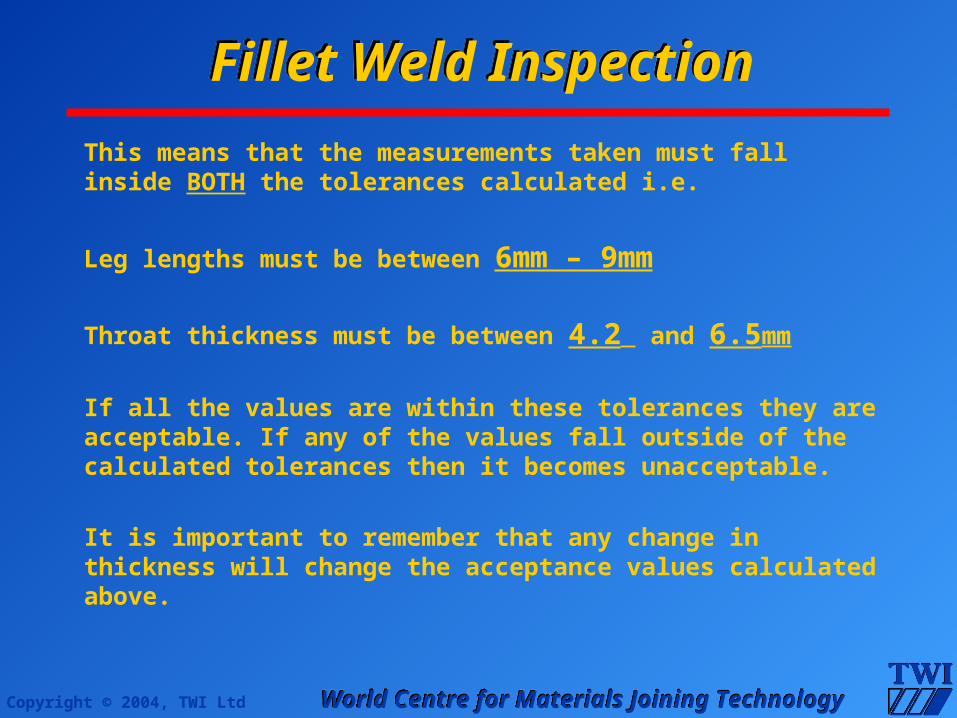
This means that the measurements taken must fall inside BOTH the tolerances calculated i.e.
Leg lengths must be between 6mm – 9mm
Throat thickness must be between 4.2 and 6.5mm
If all the values are within these tolerances they are acceptable. If any of the values fall outside of the calculated tolerances then it becomes unacceptable.
It is important to remember that any change in thickness will change the acceptance values calculated above.
Fillet Weld InspectionFillet Weld Inspection

Copyright © 2004, TWI Ltd World Centre for Materials Joining TechnologyWorld Centre for Materials Joining Technology
Vertical Leg LengthLowest leg measurement 7mmHighest leg measurement 8mm
Actual Throat ThicknessLowest throat measurement 4.5mmHighest throat measurement 8mm
Horizontal Leg LengthLowest leg measurement 5mmHighest leg measurement 10mm
Fillet Weld InspectionFillet Weld Inspection

Copyright © 2004, TWI Ltd World Centre for Materials Joining TechnologyWorld Centre for Materials Joining Technology
Practical Exam Report Sheet
Specimen Number F123 Material thickness: 6mm 1) Measure and record the following details: VERTICAL LEG LENGTH (Max & Min) = Max 8mm Min 7mm
HORIZONTAL LEG LENGTH (Max & Min) = Max 10mm Min 5mm
DESIGN THROAT THICKNESS (Max & Min) = Max 8mm Min 4.5mm
Fillet Weld InspectionFillet Weld Inspection

Copyright © 2004, TWI Ltd World Centre for Materials Joining TechnologyWorld Centre for Materials Joining Technology
2) Sentence the fillet weld dimensions using the following design criteria: MINIMUM LEG LENGTH: Material thickness (6mm)MAXIMUM LEG LENGTH: Material thickness + 3mm (9 mm) MINIMUM THROAT THICKNESS: Material thickness x 0.7 (4.2 mm)MAXIMUM THROAT THICKNESS: Material thickness + 0.5mm (6.5 mm)
The VERTICAL LEG LENGTH Please state: ACCEPT ACCEPT or REJECT?
The HORIZONTAL LEG LENGTH Please state: REJECT ACCEPT or
REJECT? The THROAT THICKNESSPlease state: REJECT ACCEPT or REJECT?
Fillet Weld InspectionFillet Weld Inspection

Copyright © 2004, TWI Ltd World Centre for Materials Joining TechnologyWorld Centre for Materials Joining Technology
Having assessed the weld for its size an inspection can then be made on the surface to locate any imperfections. Firstly; the report sheet requests the inspector to indicate the number of locations that the following imperfections occur, if any? 3) The number of places that they occur should now be entered in the box as follows: UNDERCUT APPEAR? 3 placesOVERLAP APPEAR? None LACK OF FUSION APPEAR? NoneCRACKS APPEAR? None POROSITY APPEAR? 2 AreasSOLID INCULSIONS? 1 Slag InclusionMISC: [ARC STRIKES etc] Spatter
Fillet Weld InspectionFillet Weld Inspection

Copyright © 2004, TWI Ltd World Centre for Materials Joining TechnologyWorld Centre for Materials Joining Technology
4) For the defects recorded state: MAXIMUM length (and DEPTH if applicable) of each defect
UNDERCUT: Length: 15 mm Depth:
Smooth 1.0mm OVERLAP: Length: -------- Depth: --------- LACK OF FUSION:Length: -------- Depth: --------- CRACKS: Length: -------- Depth: ---------
POROSITY: Length: 6mm Depth: Maximum Ø SOLID INCLUSIONS: Length: 4mm Depth: ---------
MISC:[ ARC STRIKES] Length: Spatter Depth: ---------
Fillet Weld InspectionFillet Weld Inspection
Copyright © 2004, TWI Ltd World Centre for Materials Joining TechnologyWorld Centre for Materials Joining Technology
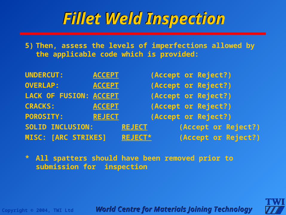
5) Then, assess the levels of imperfections allowed by the applicable code which is provided:
UNDERCUT: ACCEPT (Accept or
Reject?)OVERLAP: ACCEPT (Accept or
Reject?)LACK OF FUSION: ACCEPT (Accept or
Reject?)CRACKS: ACCEPT (Accept or Reject?)POROSITY: REJECT (Accept or Reject?)SOLID INCLUSION: REJECT (Accept or Reject?)MISC: [ARC STRIKES] REJECT* (Accept or Reject?)
* All spatters should have been removed prior to submission for inspection
Fillet Weld InspectionFillet Weld Inspection

Copyright © 2004, TWI Ltd World Centre for Materials Joining TechnologyWorld Centre for Materials Joining Technology
6) Finally accept or reject the weld used for your visual inspection as follows:
IS THE WELD ACCEPTABLE? NO YES/NO?
Signature: I C Plenty
Name: I C Plenty
Date: 01-01-04
This now completes the Fillet Welded T Joint Inspection Assessment.
Fillet Weld InspectionFillet Weld Inspection