
TW45B
84
ThyssenKrupp Aufzugswerke A company of ThyssenKrupp Elevator Operating Manual Machine TW45B
description
manual for elevator gear drive from ThyssenKrupp. Service information and dimensioning.
Transcript of TW45B

ThyssenKrupp AufzugswerkeA company
of ThyssenKrupp Elevator
Operating Manual Machine TW45B


ThyssenKrupp AufzugswerkeEin Unternehmen
von ThyssenKruppElevator
Anlageblatt zur Betriebsanleitung Maschine TW45B Appendix to instruction manual machine TW45B
Annexe aux instructions de service machine TW45B
Bremsansteuerung bei nicht TCM / TCI Brake control if not TCM / TCI Commande de frein en cas de non TCM / TCI
Anschluss TCM / TCI Steuerungen Connection TCM / TCI controls Raccordement manœuvres TCM / TCI
Betrifft: Änderung an den Bremsen 2x50Nm Subject: Modification of brakes 2x50Nm Objet: Modification des freines 2x50Nm
11.10.2007

an der Maschine (Bremsen) einbauen install at the machine (brakes) monter à la machine (freines)
an den Bremsen fixieren attach to the brakes fixer aux freines
Bremslüfthebel fixiert Fixed brake release leverLevier de desserrage de frein fixé
Rändelschraube festziehen Tighten knurled thumb screw Serrer vis moletée
Beide Bremslüfthebel sind angebracht Both brake release levers are fixed Tous les deux leviers de desserrage de frein sont fixés
einzelne Bremse lüften release single brake desserer frein séparément
Vor Einsatz des Bremslüfthebels Anlage ausschalten, Antrieb elektrisch stillsetzen Before use of the brake release lever switch off installation, stop drive electrically Avant l’usage du levier de desserrage de frein désactiver l’installation, arrêter l’entraînement électriquement
Betrifft: Neuer Bremslüfthebel für Bremse 2x50Nm Subject: New brake release lever for brake 2x50Nm Objet: Nouveau levier de desserrage de frein pour frein 2x50Nm
Bremslüfthebel spreizen Spread brake release lever Écarter levier de desserrage de frein
Beide Bremslüfthebel gleichmäßig in Richtung Handrad ziehen Pull both brake release levers equally to the handwinding wheel Tirer régulièrement tous les deux leviers de desserrage de frein vers le volant de dépannage
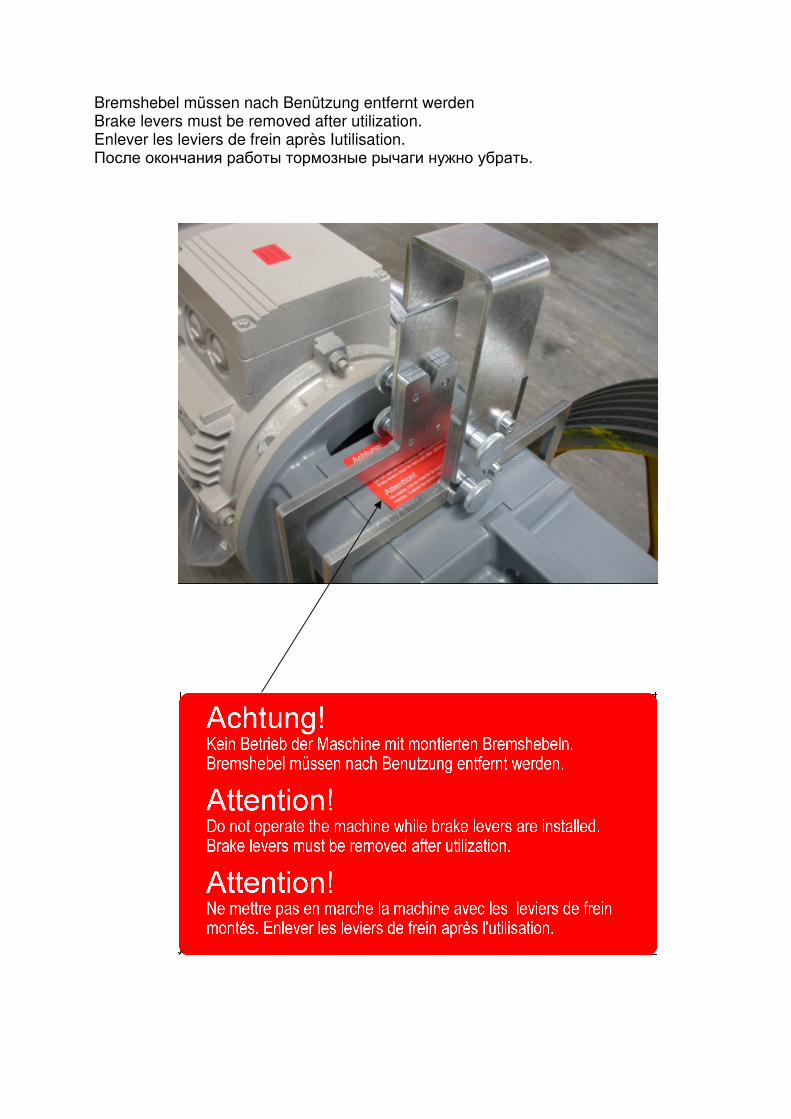
Bremshebel müssen nach Benützung entfernt werden Brake levers must be removed after utilization. Enlever les leviers de frein après Iutilisation. После окончания работы тормозные рычаги нужно убрать.

Anlageblatt zur Betriebsanleitung Maschine TW45B Appendix to instruction manual machine TW45B Annexe aux instructions de service machine TW45B Betrifft: Änderung Bremslüfthebel und el. Anschluss der Bremsen. Subject: Modification of brake release lever and electrical connection of brakes Objet: Modification du levier de desserrage de frein et raccordement électrique des freines Folgende Kapitel sind durch das Anlageblatt betroffen: The appendix refers to the following chapters: L’annexe fait référence aux chapitres suivants: 2.2 4.2 5.1 5.2 7.3 7.4

OPERATING INSTRUCTIONS
ThyssenKrupp Aufzugswerke GmbH
Imprint
All rights reserved © Copyright by: THYSSENKRUPP AUFZUGSWERKE GmbH
Postfach 23 03 70, D-70623 Stuttgart Printed in Germany These operating instructions may – even in extract form – only be reprinted or otherwise copied with the express written approval of THYSSENKRUPP AUFZUGSWERKE GmbH. All copying, distribution or saving in any form on data storage media which is not authorised by THYSSENKRUPP AUFZUGSWERKE GmbH constitutes a copyright infringement and will result in prosecution. We expressly reserve the right to carry out technical alterations which lead to an improvement of our products or increase the safety standard – also without special prior notice. The issuer responsible for the content: THYSSENKRUPP AUFZUGSWERKE GmbH
Preface
We are delighted that you have decided upon a quality product from the company THYSSENKRUPP AUFZUGSWERKE GmbH. These operating instructions will help you to get to know our products and to benefit from their intended applications. Important safety and hazard instructions will help you to operate our products safely and properly. Subject to technical alterations.


OPERATING MANUAL
ThyssenKrupp Aufzugswerke GmbH
Table of contents :
Machine TW45B PAGE
1. Safety 1.1 Explanation of symbols used 10 1.2 General safety information 11
2. Product description 2.1 Description of machine TW45B 14 2.2 Functional description 15 2.3 Dimensions 18 2.4 Technical data 24 2.5 Machine frame 28 2.6 Name plate 34 2.7 Lubrication 35
3. Transport and storage 37
4. Mounting of machine in machine room 40 4.1 Mounting of rope guard 42 4.2 Connection 43
5. Putting into service 5.1 Putting machine into service 46 5.2 Emergency operation 47
5.2.1 Drive for machine-room-less installation without emergency braking system NBS 5.2.2 Drive with emergency braking system NBS 5.2.3 Drive for machine in shaft with emergency braking system 5.2.4 (Optional) brake release levers for manual release
6. Servicing 6.1 Servicing of machine 50 6.2 Checking of drive brake 51 6.3 Checking of flank clearence 54 6.4 Checking of escaping grease / oil 55
7. Maintenance 7.1 Replacing of traction sheave - installation 57 7.2 Replacing of motor – installation 58 7.3 Replacing of brake with machine room version (TWR) 59 7.4 Replacing of brake with shaft version (MRL) 61
8. Annex 8.1 Tightening torque – mechanical strength 63 8.2 Blocking clamp 65 Manufacturer’s instruction brake / coupling
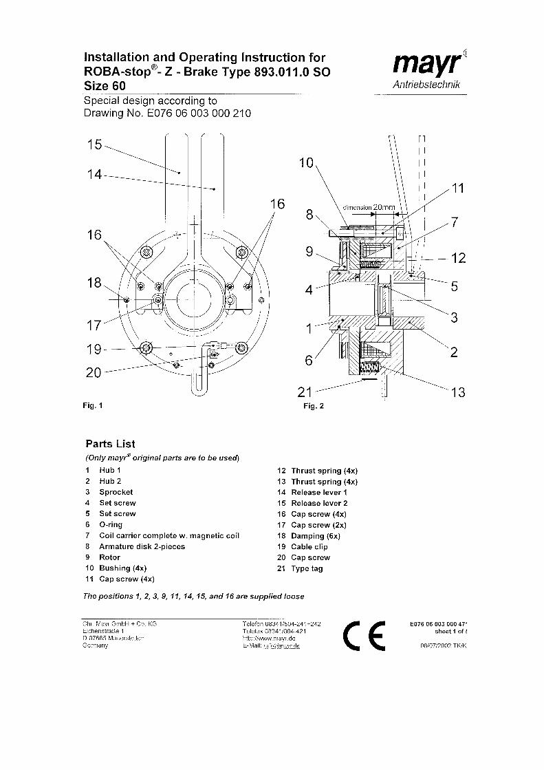
Single-disk brake – Mayr (TWR) Double-disk brake – Warner (MRL)
Encoder Manufacturer’s instruction sheets 1-3 - encoder Manufacturer’s instruction – product supplement - encoder Manufacturer’s instruction - motors
9 Version 05/2009
OPERATING MANUAL 1. SAFETY
ThyssenKrupp Aufzugswerke GmbH
1.1 Explanation of symbols used
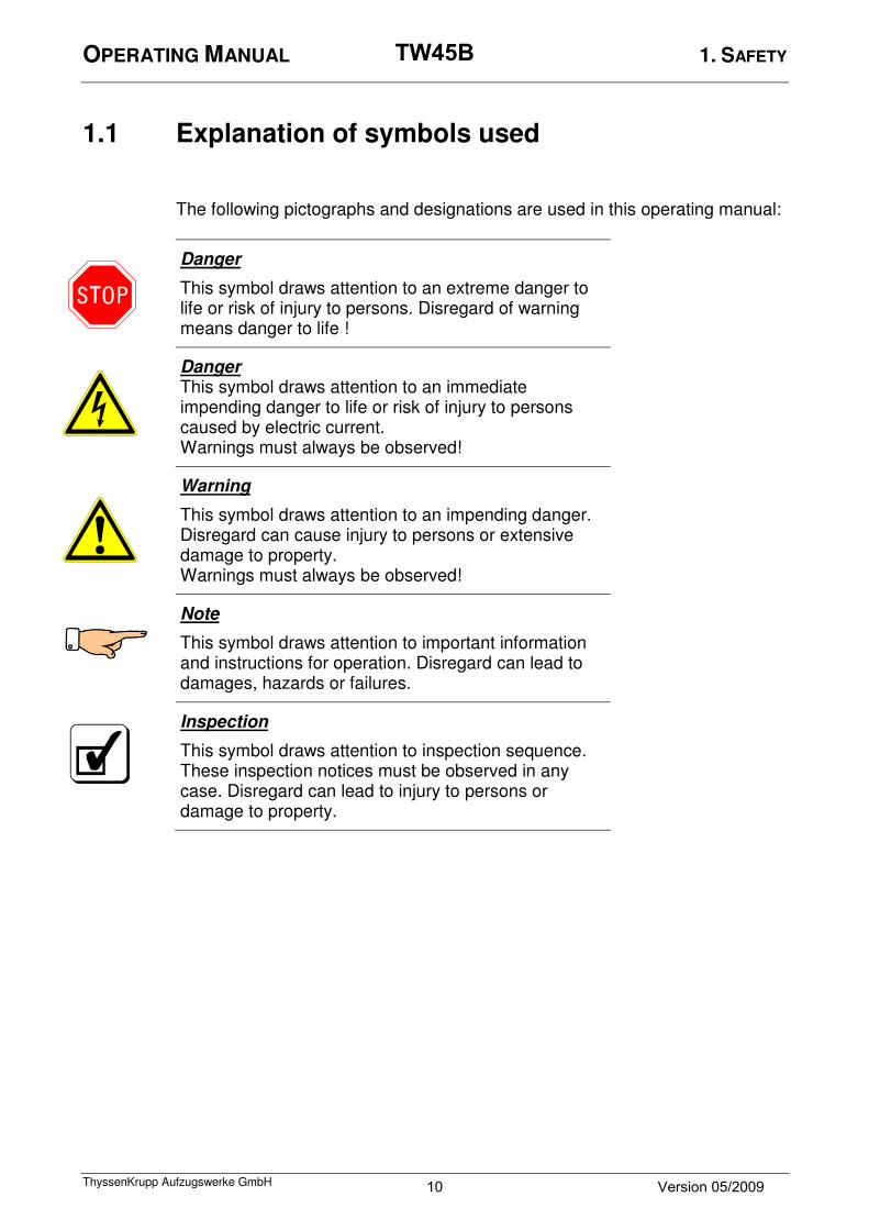
The following pictographs and designations are used in this operating manual:
Danger
This symbol draws attention to an extreme danger to life or risk of injury to persons. Disregard of warning means danger to life !
Danger This symbol draws attention to an immediate impending danger to life or risk of injury to persons caused by electric current. Warnings must always be observed!
Warning
This symbol draws attention to an impending danger. Disregard can cause injury to persons or extensive damage to property. Warnings must always be observed!
Note
This symbol draws attention to important information and instructions for operation. Disregard can lead to damages, hazards or failures.
Inspection
This symbol draws attention to inspection sequence. These inspection notices must be observed in any case. Disregard can lead to injury to persons or damage to property.
10 Version 05/2009
TW45B

OPERATING MANUAL 1. SAFETY
ThyssenKrupp Aufzugswerke GmbH
1.2 General safety information
Notes on the operating manual
Persons who perform work on the component must know the basic safety precautions to ensure safe use and failure-free operation of this component. This operating manual comprises the most important instructions how to safely use the component. The operating manual and, in particular, the safety instructions must be observed by all persons who perform any work on the component. In addition the rules and requirements concerning the regulations for prevention of accidents which apply to the installation location must be observed.
Duties of the owner and / or the installer
The owner and / or the installer ensure that work on the component shall only be performed by trained and qualified persons who
• observe the accident prevention regulations;
• have read the safety information and the warning notices in this operating manual.
Note: Check whether these instructions are observed in regular intervals.
Duties of the employees
Persons who perform work on the component must
• observe the accident prevention regulations and safety precautions;
• read the safety information and the warning notices in this operating manual prior before they start working.
Training of the employees
Work on this component shall not be performed by other than trained and qualified persons. These persons shall not perform any work other than the instructions given for putting into service, operation, maintenance and repair work.
Organizational measures
The owner or the installer must provide the necessary personal protective gear. All existing safety devices must be checked regularly in accordance with the maintenance plan.
11 Version 05/2009
TW45B
OPERATING MANUAL 1. SAFETY
ThyssenKrupp Aufzugswerke GmbH
Informal information about safety measures
• The operating manual must always be available at the location of the installation.
• In addition to the operating manual the general and local regulations for the prevention of accidents and environmental regulations must be made available and observed.
• Clearly and easily visible statutory safety instructions must be made available for the users.
• See to it that all information concerning safety and hazards is always visibly and legibly made available on the machine.
Use as intended
TW45B is exclusively designed in accordance with the state of the art and the recognized safety regulations. TW45B shall only
• be used for its intended purpose
• be used exclusively if safe operation is ensured.
TW45B drive shall exclusively be used as drive for lifts. Any other use or any use exceeding the scope of the above definitions is regarded as use outside of the intended purpose. THYSSENKRUPP AUFZUGSWERKE GmbH cannot be hold liable for any damages resulting from this and for any damages which are caused by any errors of procedure. Use within the scope of its intended purpose also comprises
• observance of all information of the operating manual
• fulfilment of the instructions applying to putting into service, installation description and inspection and repair work.
Guarantee and liability
The „General sales and delivery terms“ of THYSSENKRUPP AUFZUGSWERKE GmbH apply generally. Any claims for guarantee and liability are excluded in the case of injury to persons or damage to property resulting from one or several of the causes below:
• use of TW45B outside the scope of its intended purpose
• inexpert mounting, putting into service, operating and maintaining of
TW45B
• operating the TW45B with defective and/or non-operative safety and protective devices
• disregard of and instructions of the operating manual that apply to
transportation, storage, mounting, putting into service, operating and maintaining of TW45B
• unanauthorized constructional modifications of TW45B
• unauthorized modification of drive (performance etc.)
12 Version 05/2009
TW45B
OPERATING MANUAL 1. SAFETY
ThyssenKrupp Aufzugswerke GmbH
• unsatisfactory supervision of parts which are subject to wear
• inexpert repair work
• catastrophes caused by outside influence and Act of God.
Modifications of machine TW45B
TW45B is delivered factory-adjusted, pre-assembled and ready for operation. In the case of any modifications of the machine THYSSENKRUPP AUFZUGSWERKE GmbH cannot be hold liable. Attention : the machine is delivered with oil filled in ! Please check oil level using gauge glass before you start operation.
Use of TW45B and possible hazards
Traction sheave and handwheel of TW45 B do not have any protective cover. The drive shall only be operated in a closed machine room. See to it that the necessary safety distance to all revolving parts (marked yellow) is observed by persons working in the machine room. Note: danger of injury caused by objects (such as tools etc.) placed on the handwheel. In case of inexpert use there will be the risk of damage to the user or third parties or impairment of the component or material property. Failures which may affect safe operation must be eliminated immediately. Attention: works on the handwheel shall only be performed with the power supply switched off and the drive protected against unintentional switching on (e.g. by locking of key-operated switch or removing of power supply fuses). A warning sign to that effect must be provided at the control cabinet when performing works at the drive. Emergency brake NBS: installation sequence is different with emergency brake mounted on. The same applies to testing and setting. Observe notes in enclosed operating manual.
Attention: the model for placement in the shaft (MRL) is delivered without manual release. Handwheel operation is only possible using proper electrical accessories which are not part of the supply schedule. The manufacturer of the lift installation must provide proper measures:
a) to be able to operate the brake in cases of emergency (power failure).
b) to be able to lift the car when the safety gear is engaged. (For example rope device at car or counterweight.) c) to be able to check the two brake circuits separately.
13 Version 05/2009
TW45B

OPERATING MANUAL 2. PRODUCT DESCRIPTION
ThyssenKrupp Aufzugswerke GmbH
2.1 Description of machine TW45B
Machine TW45B (vertical motor position) consists of:
1 Handwinding wheel 7 Rope guard
2 Real value generator 8 Rope guard support
3 Motor 9 Gear
4 Transport eyebolt 10 Disk brake
5 Traction sheave 11 Brake release lever
6 Disk at traction sheave shaft 12 Motor connection
1
2
3
4
5
12
11
6
9
8 7
10
7
Fig. 1
4
Figure: TW45B, vertical motor position, machine in machine room
14 Version 05/2009
TW45B

OPERATING MANUAL 2. PRODUCT DESCRIPTION
ThyssenKrupp Aufzugswerke GmbH
Versions:
Two versions are available:
a) Vertical and horizontal motor position for machine in machine room (TWR)
b) Horizontal motor position for machine in shaft (MRL)
Compared to version with machine in machine room (TWR) the model of the machine for use in shaft (MRL) is equipped with two-surface disc brakes in tandem arrangement with higher braking torque but without mounted-on brake release levers and handwinding wheel. The following versions are available:
Drive rating Gear ratio Traction sheave version Traction sheave in left-hand and right-hand design with horizontal motor position (seen from motor to gear) Encoder version
An optionally mounted emergency braking system NBS prevents overspeed in upwards direction. It has an additional disk brake acting on the traction sheave shaft.
Note: It is not possible to retrofit an existing machine with an NBS emergency braking system !
2.2 Functional description
Machine TW45B is designed for driving lift cars with rated load 450 kg and
speed 1,0 ≤ v ≤ 1,25 m/s.
The gear (shaft) consists of a single-stage worm gear in monoblock housing with separated AS/BS bearing brackets. A flexible coupling transmits the power from motor to gear. A dual-circuit disc brake is installed between motor and gear. An overhung traction sheave is used. Tooth system operating in synthetic oil.
Attention: the gear can be considered self-locking for ratio > 25.5. Observe that this does not apply to lower ratio.
Different designs of drives are used dependent on the position of the flanged three-phase motor. The drive transmits power to the worm shaft and from there to the worm wheel, traction sheave shaft and traction sheave.
TW45B has flange-mounted motors (∅250 mm) in B5 / V1 design. Integrated posistors protect the motor against thermal overload. The thermal motor monitoring is connected in the motor terminal box. Details see chapter 2.4.
15 Version 05/2009
TW45B

OPERATING MANUAL 2. PRODUCT DESCRIPTION
ThyssenKrupp Aufzugswerke GmbH
Drive type: TW45B is available with frequency-controlled three-phase motor only. An encoder for speed monitoring is available optionally. It is mounted on the motor shaft. Technical data and manufacturer’s instrutions for available encoder versions see chapters 8.3 – 8.5 A mounted-on handwinding wheel is available with drives models with machine in machine room (TWR). Coupling: Worm wheel and rotor shaft of motor are connected through a flexible, maintenance-free coupling. The coupling half connected to the gear has a sprocket, which transmits the drive movement to the brake rotor of the disc brake. Brake:
Note: the brakes of the TW45B machine are intended for static applications as holding brakes. Any dynamic braking is restricted to emergency and test braking. Normal use will not lead to any noticeable wear of lining. These brakes can in no way replace the safety braking systems required for downwards travelling cars.
Function:
Two different operational brake designs are used with TW45B.
a) A two-surface disc brake with radial armature base plate designed for version with machine in machine room (TWR). Two independently operating radial armature base plates press onto the brake lining of the rotor. The disc moves on the hub, forces the friction lining onto the gear housing and is thus stopped.
b) A two-surface disk brake with two brake rotors in tandem arrangement for version with machine in shaft (MRL). Two independently operating armature base plates with preset spring resistance press onto the brake lining of the rotors. The two discs move on the coupling hub, force the friction lining onto the bearing cover and armature base plate and are thus stopped.
The torque of the two spring-operated brakes has been adjusted at the factory and shall not be re-adjusted. The braking force is adjusted in such a way that one brake shoe con stop the car loaded with full loading capacity. The disc brakes are released through electrically-operated magnetic clamps. Manual release of brake is only possible with machine in machine room (TWR). The brake release levers at transition motor-gear (fig. 1, pos. 11) must be operated. When the brake release levers are pressed, the armature base plate and the rotor are separated. (fig. 25, pos. 5) The rotor is connected to the motor and the worm shaft through a toothing system; the brake is released. Tooth system for vertical motor position Drawing and important manufacturer’s instructions related to installation and details see chapter 8.2.1.
16 Version 05/2009
TW45B

OPERATING MANUAL 2. PRODUCT DESCRIPTION
ThyssenKrupp Aufzugswerke GmbH
Note: TW45B machine for placement in shaft (MRL) does not have mounted-on brake release levers. Manual release of the brake is not possible!
Emergency braking system NBS:
The optional NBS emergency braking system protects the elevator car travelling upwards from overspeed. Description and details of the emergency braking system see operating manual NBS. Traction sheave:
The one-piece (rim and hub) traction sheave is fixed using a cone and a mounting plate overhanging the shaft drive. Further details see chapter 2.4 Technical data. Pulse generator: An overview of pulse encoders used incl. technical data see chapter 8.3 and manufacturer’s instructions in chapters 8.4 – 8.5. Environmental conditions:
Surrounding at the final site of the drive (humidity, temperature) shall comply with the requirements for machine rooms (between +5° and +40° C according to EN81.) Relative humidity of air shall not exceed 70%.
Attention: the torque of the two-surface disc brake can intensively drop by dewing in case of temperature around or under the freezing point. There is the danger that friction linings seize up at the friction surfaces in case of standstill for longer time. The user of the assembly must provide proper counter measures.
17 Version 05/2009
TW45B

OPERATING MANUAL 2. PRODUCT DESCRIPTION
ThyssenKrupp Aufzugswerke GmbH
2.3 Dimensions
Manual release mounting
TW45B vertical motor position (version for machine in machine room (TWR) with NBS)
Fig. 2
Fig. 3
200
approx. 991
Manual release operational brake
Motor connection Oil drain
Pulse generator
18 Version 05/2009
TW45B
OPERATING MANUAL 2. PRODUCT DESCRIPTION
ThyssenKrupp Aufzugswerke GmbH
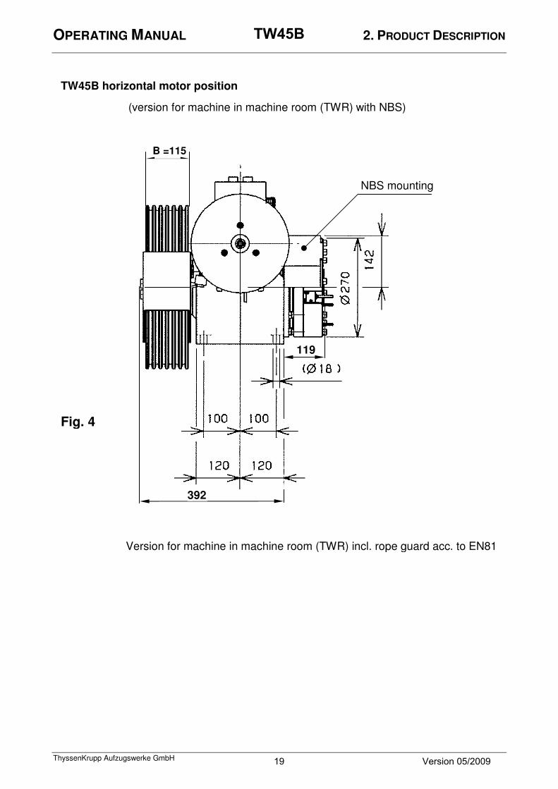
Fig. 4
TW45B horizontal motor position
B =115
NBS mounting
392
119
(version for machine in machine room (TWR) with NBS)
Version for machine in machine room (TWR) incl. rope guard acc. to EN81
19 Version 05/2009
TW45B

OPERATING MANUAL 2. PRODUCT DESCRIPTION
ThyssenKrupp Aufzugswerke GmbH
TW45B (TWR) vertical motor position
Fig. 5 Fig. 6
Oil level gauge glass
Oil drain
Brake release lever
Version for machine in machine room (TWR) incl. rope guard acc. to EN81
20 Version 05/2009
TW45B

OPERATING MANUAL 2. PRODUCT DESCRIPTION
ThyssenKrupp Aufzugswerke GmbH
Fig. 7
Fig. 8
21 Version 05/2009
TW45B
OPERATING MANUAL 2. PRODUCT DESCRIPTION
ThyssenKrupp Aufzugswerke GmbH
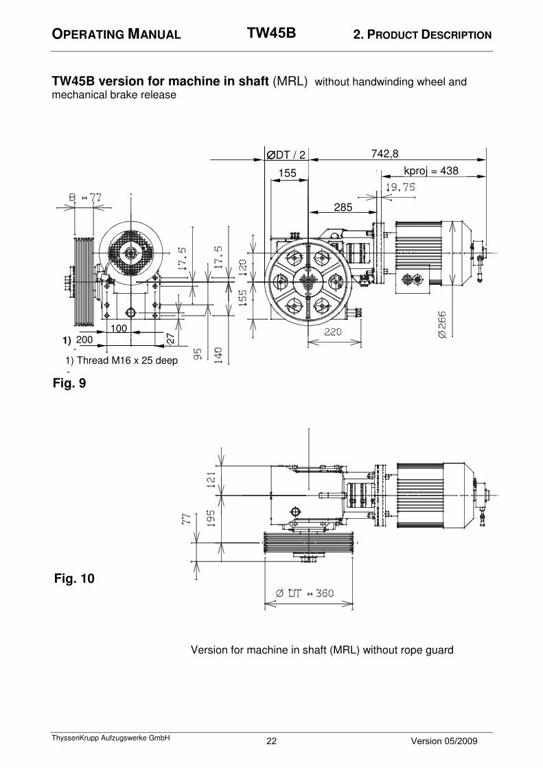
TW45B version for machine in shaft (MRL) without handwinding wheel and mechanical brake release
200
Fig. 10
∅∅∅∅DT / 2
155 kproj = 438
285
742,8
Fig. 9
100 200 1)
1) Thread M16 x 25 deep
27
Version for machine in shaft (MRL) without rope guard
22 Version 05/2009
TW45B

OPERATING MANUAL 2. PRODUCT DESCRIPTION
ThyssenKrupp Aufzugswerke GmbH
TW45B version for machine in shaft (MRL) rear view
Fig. 11
393
1)
1)
1) Thread M16 x 25 deep
1)
1)
1)
1)
23 Version 05/2009
TW45B

OPERATING MANUAL 2. PRODUCT DESCRIPTION
ThyssenKrupp Aufzugswerke GmbH
2.4 Technical data
Gear unit:
Gear type: TW45B
Manufacturer: ThyssenKrupp Aufzugswerke GmbH
Application: Machine room (TWR)
Shaft (MRL)
Axle distance: [mm] 120
Gear ratio: 46:1; 32:1 40:3
Oil filling: [liter] approx. 5,5
Type of oil: Synthetic gear oil (polyalkylenglycol)
Sort of oil: SM1 (TRIBOL 800 / ISO 460)
Circumferential
backlash:
[°] 0,03 ÷ 0,07
Weight (machine) [kg] approx. 105
Designed for use in installations with rated load of 450 kg and
vrat 1,0 ≤ vn ≤ 1,25 m/s
Permissible radial load of traction sheave: max. 26 kN Mass moment of inertia:
component gear motor hand wheel total
J1 [kgm²] 0.0045 0.018 0.01 0.0325
24 Version 05/2009
TW45B
OPERATING MANUAL 2. PRODUCT DESCRIPTION
ThyssenKrupp Aufzugswerke GmbH
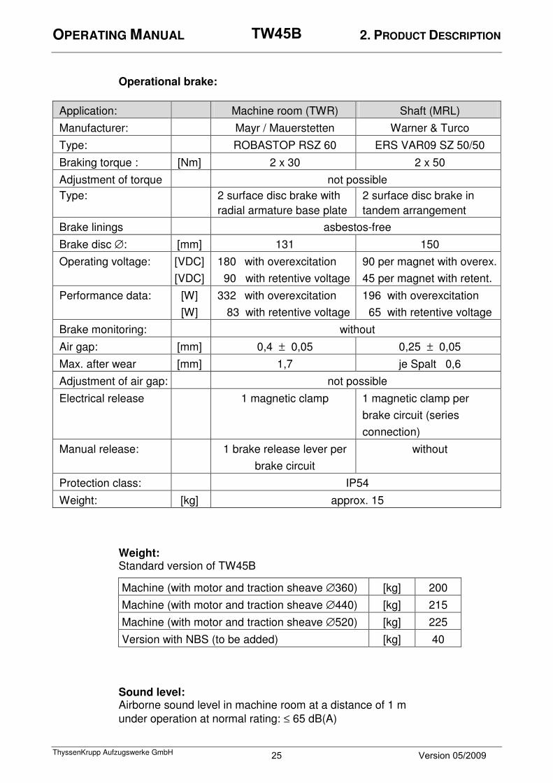
Operational brake:
Application: Machine room (TWR) Shaft (MRL)
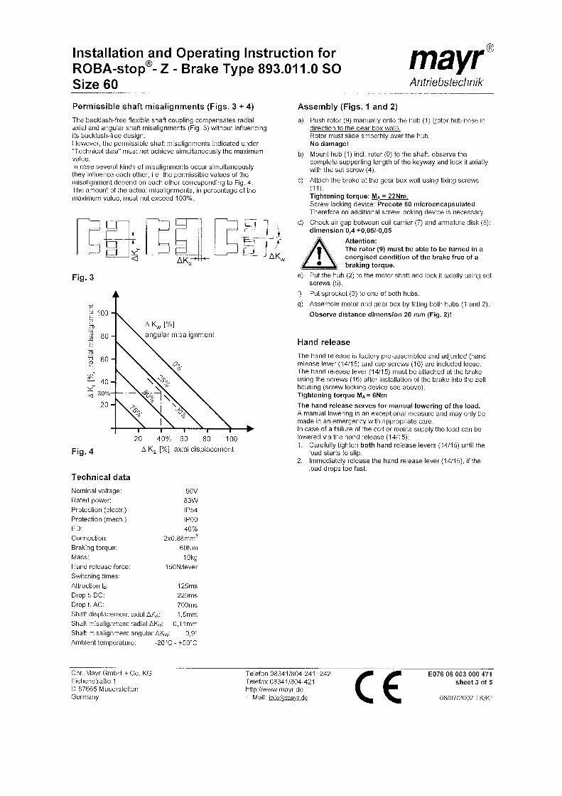
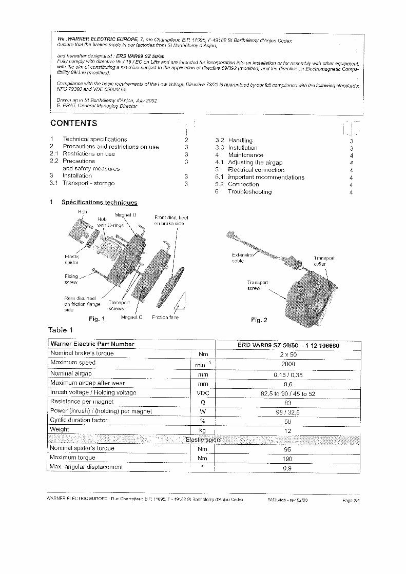
Manufacturer: Mayr / Mauerstetten Warner & Turco
Type: ROBASTOP RSZ 60 ERS VAR09 SZ 50/50
Braking torque : [Nm] 2 x 30 2 x 50
Adjustment of torque not possible
Type: 2 surface disc brake with
radial armature base plate
2 surface disc brake in
tandem arrangement
Brake linings asbestos-free
Brake disc ∅: [mm] 131 150
Operating voltage: [VDC]
[VDC]
180 with overexcitation
90 with retentive voltage
90 per magnet with overex.
45 per magnet with retent.
Performance data: [W]
[W]
332 with overexcitation
83 with retentive voltage
196 with overexcitation
65 with retentive voltage
Brake monitoring: without
Air gap: [mm] 0,4 ± 0,05 0,25 ± 0,05
Max. after wear [mm] 1,7 je Spalt 0,6
Adjustment of air gap: not possible
Electrical release 1 magnetic clamp 1 magnetic clamp per
brake circuit (series
connection)
Manual release: 1 brake release lever per
brake circuit
without
Protection class: IP54
Weight: [kg] approx. 15
Weight:
Standard version of TW45B
Machine (with motor and traction sheave ∅360) [kg] 200
Machine (with motor and traction sheave ∅440) [kg] 215
Machine (with motor and traction sheave ∅520) [kg] 225
Version with NBS (to be added) [kg] 40
Sound level:
Airborne sound level in machine room at a distance of 1 m
under operation at normal rating: ≤ 65 dB(A)
25 Version 05/2009
TW45B

OPERATING MANUAL 2. PRODUCT DESCRIPTION
ThyssenKrupp Aufzugswerke GmbH
Motor data:
VVVF three-phase motor in B5 design The following motor operational specifications apply to the use of TAW frequency converters of type CPI10; CPI15/15E; CPI26E.
Machine room (TWR) Application
Shaft (MRL)
Manufacturer: Siemens AG
Type: 1LA7130-4AA19Z 1LA7133-4AA19Z
Voltage / frequency: [V/Hz] 340 / 42
S5 – operational data 180 c/h – 50%ED
Speed range: [1/min] 1000 ⇒ 1249 1250 ⇒ 1800 1250 ⇒ 1415
Rating: [kW] 4,2 ⇒ 5,2 5,2 7
Torque range for speed: [Nm]
[1/min]
40
1000 ⇒ 1249
40 ⇒ 28
1250 ⇒ 1800
52 ⇒ 46
1250 ⇒ 1415
Rated current: [A] 12,5 16,5
Allowable starting
torque
[Nm] 70 70 ⇒ 63 88
Allowable starting
current:
[A] 20 32
Efficiency: 0,84 0,82
Design: IMB5/V1
Protection class: IP54
Ventilation: Integrated ventilator
Handwinding wheel: [mm] ∅ 270 (plastic) without 1)
kproj. ( see fig. 2 + 7) [mm] 485
Weight: [kg] 50 60
Real value generator
(standard)
WDG100-38-1024/4096 TTL
Real value generator
(special)
WDG100-38-1024 HTL
WDG100-38-1024 sine/cosine 1) For use in the shaft (MRL) The electrical data applies to the following environmental conditions:
• max. altitude 1000 m above sea level
• max. temperature + 40 °C at max. 50% air humidity
• max. relative humidity 70 % at 20 °C
If the conditions listed above are exceeded, derating as set out in VDE0530 applies.
The connecting cable at the real value generator is 10 m long. A connector is provided at the cable end of the standard generator (1024 TTL).
26 Version 05/2009
TW45B

OPERATING MANUAL 2. PRODUCT DESCRIPTION
ThyssenKrupp Aufzugswerke GmbH
Motor connection:
Motor connection see chapter 4.2. The terminal diagram is imprinted or enclosed at the inside of the terminal block . Traction sheave:
The monobloc traction sheaves overhanging the shaft drive are fixed using a cone. Groove type: seat or V-grooves
Hardened groove flanks as standard (≥ 50 HRc)
Application: Machine room Shaft
Diameter - DT [mm] 440 520 360
Rim width: [mm] 115 77
Max. grooves
– z ∗ d
[mm] 7 ∗ ∅ 8
6 ∗ ∅ 10
6 * ∅ 11
7 ∗ ∅ 8
6 ∗ ∅ 10
6 * ∅ 11
5 * ∅ 12
5 * ∅ 8
Groove type/
undercut angle:
[°] acc. to order
Weight: [kg] 45 55 30
Material: specially alloyed EN-GJL 250
(HB 190 to 230)
Note: Emergency braking system NBS see separate operating manual NBS.
27 Version 05/2009
TW45B

OPERATING MANUAL 2. PRODUCT DESCRIPTION
ThyssenKrupp Aufzugswerke GmbH
2.5 Machine frame TW45B (optional)
The machine base frame consists of brackets of plate edge construction with two welded face plates.
It is designed for use with machines with horizontal motor position.
A hole grid in the machine frame allows the machines with vertical motor
position to be moved in increments for customer-specific arrangement.
Standard models for machines in machine room and in shaft:
1. With deflection pulley, for direct rope departure to be used in: a) installations with 1:1 rope suspension for car – counterweight rope
distance ASL ≤ 620 mm and car – traction sheave rope distance
∅ 520 mm
b) installations with 2:1 rope suspension. See tables model 1, shown in fig. 12.
The frame is installed using impact soundproof elements.
2. With deflection pulley, frame with deflection pulley ∅ 360 or
∅ 450 mm and variable rope distance in left-hand or right-hand design used for installations with 1:1 rope suspension and
ASL : 608 ≤ ASL ≤ 833 mm. (depending on position of deflection pulley. See tables model 2, shown in fig. 13
Note: frames 2 have supports to house the deflection pulleys. Arrangement and dimensions shown in fig. 13 and table for model 2. Installation
Machine frames are installed in the machine room using soundproof elements. These elements differ depending on the installation:
a) Isolation elements 100 x 100 x 50 mm high without base. (60 309 01 14 0) To be used for installation of machine directly on the machine room floor without plaster floor or directly on the plaster floor.
b) Isolation elements as above, but with base 140 x 140 x 80 mm high. (60 300 04 37 0) To be used for installation of machine on plaster floor, base casted in plaster
floor. (covering thickness ≤ 60 mm)
28 Version 05/2009
TW45B

OPERATING MANUAL 2. PRODUCT DESCRIPTION
ThyssenKrupp Aufzugswerke GmbH
Frame mounting (frame without deflection pulley)
• Screw the frame delivered disassembled together in the machine room. See to it that the supports with additional (two) bore holes and the rope pulley are mounted on the proper side. (The side where the deflection pulley is to be arranged.)
• Mount and secure deflection pulley and axle to pulley support.
• Arrange and align frame on isolation elements in accordance with layout drawing.
• Tighten the fastening screws with the pre-set torque.
• Mount machine on frame using hoist, the traction sheave must be at the deflection pulley side.
• Laterally move machine on frame until the required ASL measure (rope distance car - counterweight at rope departure) is reached.
• Screw machine and frame together. Observe not to distort the machine housing. To ensure that the base is perfectly horizontal put enclosed metal plates under, if required.
• Align the rope grooves of the traction sheave so that they are in parallel line to the rope grooves of the deflection pulley.
• Tighten the fastening screws with the pre-set torque. See chapter 8.1.
• Align the rope departure so that it is in vertical line with the rope pulley at the car and/or the fastening at the car or counterweight.
Attention: in case of lateral or diagonal rope departure the gear box casing is to be secured against shifting using plates bolted to the machine frame.
Explanation of abbreviations:
ASL = parallel distance of ropes at rope departure (fig. 13)
∅DT = diameter of traction sheave
∅SR = diameter of deflection pulley
α = angle of wrap at traction sheave
With frame model 1, fig. 12 X1 = distance 1 between rope departure and outer edge of frame X2 = distance 2 between rope departure and outer edge of frame
With frame model 2 fig. 13 X1 = distance 1 between axle center of rope pulley and bearing surface
of frame support at machine frame X2 = distance 2 between rope departure and outer edge of frame support Y1 = vertical axle distance between traction sheave and deflection pulley Y2 = vertical distance between deflection pulley center and support bearing Z1 = distance 1 between center of rope departure and outer edge frame support at deflection pulley side 1) – 2) See remarks representation fig. 1 (fig. 12)
29 Version 05/2009
TW45B

OPERATING MANUAL 2. PRODUCT DESCRIPTION
ThyssenKrupp Aufzugswerke GmbH
Data machine frame model 1
Shown in fig. 12
Arrangement of machine
left right
Traction
sheave
diameter
DT x1 min x1 max x2 min x2 max
440 [mm] 52 342 52 342
520 [mm] 52 262 52 262
Weight: machine frame 1 without supports and deflection pulley approx. 50 kg
Note: left or right means that the machine 1) in right-hand design (traction sheave seen from motor towards machine) can be moved in respective direction to outer mounting holes in the frame.
x1 or x2 is the distance between rope departure and outer edge of machine
frame dependent on the traction sheave ∅.
30 Version 05/2009
TW45B

OPERATING MANUAL 2. PRODUCT DESCRIPTION
ThyssenKrupp Aufzugswerke GmbH
Data machine frame model 2 Shown in fig. 13
Rope distance measurements (ASL) and angle of wrap αααα
(Intermediate results for ASL measurements can be adjusted in increments of 40 mm in accordance with the mounting holes in frame)
Minimum rope distance car – counterweight and
Maximum angle of wrap
ASLmin [mm] and αmax [°]
With deflection pulley ∅SR [mm]
360 450
Traction sheave diameter
DT
[mm]
ASLmin αmax ASLmin αmax
440 582 167 566 168
520 662 167 616 170
Maximum rope distance car – counterweight and
Minimum angle of wrap
ASLmax [mm] and αmin [°]
with deflection pulley ∅SR [mm]
360 450
Traction sheave diameter
DT
[mm]
ASLmax αmin ASLmax αmin
440 832 149 776 150
520 832 154 776 157
Project planning dimensions see fig. 13
Deflection pulley
∅ SR [mm]
Measure x1
[mm]
Measure x2
[mm]
Measure y1
[mm]
Measure y2
[mm]
Measure z1
[mm]
360 130 61 645 190 245
450 231 116 600 235 255
Weight:machine frame model 2 incl. deflection pulley ∅ 360 approx .140 kg
incl. deflection pulley ∅ 450 approx.170 kg
31 Version 05/2009
TW45B

OPERATING MANUAL 2. PRODUCT DESCRIPTION
ThyssenKrupp Aufzugswerke GmbH
Model 1 Machine frame TW45B without deflection pulley
Remarks:
1) Machine with horizontal motor position / traction sheave right
2) Machine with horizontal motor position / traction sheave left
3) Machine with vertical motor position / traction sheave right
4) Machine with vertical motor position / traction sheave left
Fig.12
32 Version 05/2009
TW45B

OPERATING MANUAL 2. PRODUCT DESCRIPTION
ThyssenKrupp Aufzugswerke GmbH
Model 2 Machine frame TW45B with deflection pulley
Shown with rope pulley position in right-hand design (left-hand design mirror-inverted)
Explanation of remarks see version 1 fig. 12
Fig. 13
33 Version 05/2009
TW45B

OPERATING MANUAL 2. PRODUCT DESCRIPTION
ThyssenKrupp Aufzugswerke GmbH
2.6 Name plate of TW45B
The current model and the technical data are stated on the nameplate of the product.
1. Name plate of gear (ThyssenKrupp Aufzugswerke):
2. Name plate of gear (Lift Equip) 3. Name plate of motor (laterally fastened at the motor) 4. Name plate of operational brake:
(With vertical motor position fastened at motor flange below brake covering)
34 Version 05/2009
TW45B
OPERATING MANUAL 2. PRODUCT DESCRIPTION
ThyssenKrupp Aufzugswerke GmbH
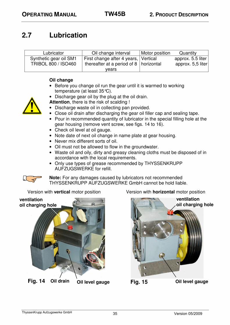
2.7 Lubrication
Lubricator Oil change interval Motor position Quantity Synthetic gear oil SM1 TRIBOL 800 / ISO460
First change after 4 years, thereafter at a period of 8
years
Vertical approx. 5.5 liter horizontal approx. 5,5 liter
Oil change
• Before you change oil run the gear until it is warmed to working temperature (at least 35°C).
• Discharge gear oil by the plug at the oil drain. Attention, there is the risk of scalding !
• Discharge waste oil in collecting pan provided.
• Close oil drain after discharging the gear oil filler cap and sealing tape.
• Pour in recommended quantity of lubricator in the special filling hole at the gear housing (remove vent screw, see figs. 14 to 16).
• Check oil level at oil gauge.
• Note date of next oil change in name plate at gear housing.
• Never mix different sorts of oil.
• Oil must not be allowed to flow in the groundwater.
• Waste oil and oily, dirty and greasy cleaning cloths must be disposed of in accordance with the local requirements.
• Only use types of grease recommended by THYSSENKRUPP AUFZUGSWERKE for refill.
Note: For any damages caused by lubricators not recommended THYSSENKRUPP AUFZUGSWERKE GmbH cannot be hold liable.
Version with vertical motor position Version with horizontal motor position
Fig. 15 Oil drain
ventilation
oil charging hole
ventilation
oil charging hole
Oil level gauge
Oil level gauge Fig. 14
35 Version 05/2009
TW45B
OPERATING MANUAL 2. PRODUCT DESCRIPTION
ThyssenKrupp Aufzugswerke GmbH
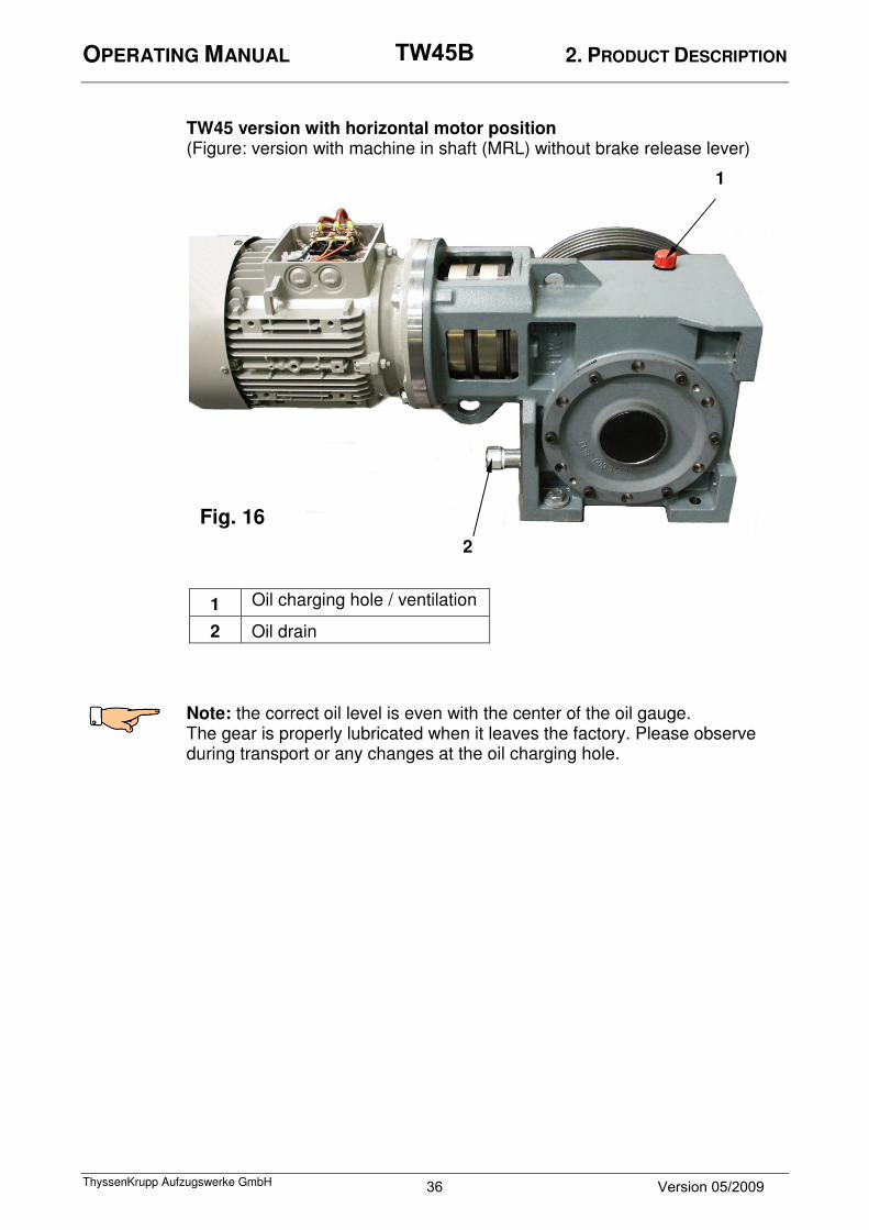
TW45 version with horizontal motor position
(Figure: version with machine in shaft (MRL) without brake release lever) Note: the correct oil level is even with the center of the oil gauge. The gear is properly lubricated when it leaves the factory. Please observe
during transport or any changes at the oil charging hole.
1
2
1 Oil charging hole / ventilation
2 Oil drain
Fig. 16
36 Version 05/2009
TW45B

OPERATING MANUAL 3. TRANSPORT AND STORAGE
ThyssenKrupp Aufzugswerke GmbH
3. Transport and storage
Packing: TW45B without frame is delivered securely mounted to a Europallet. The traction sheave is enclosed. Machines with frames are delivered with frame disassembled. Optionally the machine may be delivered completely assembled and aligned.
For transport by sea, machine and accessories are shipped in seaworthy crates. Transport:
The safety precautions are to be observed and the machine and frame must be perfectly horizontal, both in cross and lengthwise direction.
Attention: machine is filled with oil. Make sure that it is always
transported and stored in vertical position.
Transport by forklifts:
• Always lift the machine, not transport pallet ! Secure machine against tilting.
• Pay attention to projecting parts. Risk of injury to persons or damage to property !
Transport by crane:
• Do not stay below suspended loads!
• Lift machine without frame using transport eyebolts and rope. Hook bolts on the shaft are not suitable for handling the machine !
• Secure transport rope at frame in case of machine assembled on machine frame.
• Protect the machine against tilting.
Rope fastening: fasten transport rope at eyebolts in case of machine without machine frame. See fig. 17 or 18 Use transport eyebolts below motor with vertical motor position.
Protect handwinding wheel against damage. Ropes and chains shall not be adjacent to handwinding wheel during transport.
Vertical motor position
Fig. 17
37 Version 05/2009
TW45B

OPERATING MANUAL 3. TRANSPORT AND STORAGE
ThyssenKrupp Aufzugswerke GmbH
Use transport eyebolts at motor and gear box housing with motor in horizontal position.
Protect handwinding wheel against damage. Ropes or chaines shall not be close to handwinding wheel during transport.
Note the pictographs fastened on the packing or on other visible places.
Top Handle with care Keep dry
Do not expose to
heat
Do not use hand-
held grippers
Fasten here
Dimensions and weight
The weight is indicated on a sticker on the packing. For dimensions see delivery note. For rough data see 2.3 Technical data
Examination by customer on receipt of goods
Examine the delivered parts for completeness, damage or anything strange. Report and document shipping damage
After receipt of goods make sure that there is no damage caused during transport.
Fig. 18
Motoranordnung horizontal Horizontal motor position
38 Version 05/2009
TW45B

OPERATING MANUAL 3. TRANSPORT AND STORAGE
ThyssenKrupp Aufzugswerke GmbH
Information
• Immediately document the damaged noticed (drawing, photograph, description of damage).
• Send the respective documents immediately to THYSSENKRUPP AUFZUGSWERKE GmbH.
Unpacking
Information
• Dispose packing equipment in accordance with the environmental standards or make it available for further use.
• Special transport aids and transport contrivances shall not be sent back to THYSSENKRUPP AUFZUGSWERKE GmbH but remain at the customer.
Intermediate storage
• Even if the component is not mounted directly after delivery, it should be stored in dry places and protected with humidity-proof covering.
• Do not store the component in the open air. Parts without surface coating lack long-time preservation.
Note: do not damage surface coating and preservation ! Mechanical (scratches), chemical (acids, alkalines) or thermal (sparks, welding beads, heat) damages may cause corrosion and thus failure of surface protection.
Environmental conditions
Information
Surrounding at the final site of the machine (humidity, temperature) shall comply with the requirements for machine rooms. (Between +5° and +40° C according to EN 81)
39 Version 05/2009
TW45B

OPERATING MANUAL 4. MOUNTING OF MACHINE
ThyssenKrupp Aufzugswerke GmbH
4. Mounting of machine in machine room
General installation instructions:
Installation shall only be performed by trained and competent persons. Utmost care must be taken. ThyssenKrupp Aufzugswerke GmbH cannnot be hold liable for any damage caused by inexpert installation. Sufficient free area around the drive must be ensured for installation, maintenance and cleaning works. Sufficient lifting devices must be provided for installation works. Attention: do not perform any welding works at the drive. The drive is not suitable as connection to earth. Gear teething or bearing parts may be impaired.
Attention: use all mountings available. Mounting are subjected to respective design. Ensure that air supply for cooling the drive is not affected. It must be possible to check the oil level.
Place of installation / base:
Ensure that the place of installation is perfectly horizontal, with max. tolerance of 0.5 mm. The base must also be perfectly horizontal both in cross and lengthwise, verify that it is stable enough for the forces acting on the base. Installation (machine delivered without frame or disassembled): Remove packing, arrange machine on base. Remove surface coating at worm wheel shaft, connection and traction sheave bores.
Attention: do not touch shaft sealing ring when performing any cleaning works !
Ensure proper ventilation. Do not smoke.
Mount traction sheave to machine. (See chapter 7.1) Secure traction sheave by tightening the screws using torque wrench. Note tightening torque (75Nm). See chapter 8.1 Machines with machine frame and rope pulley are mounted in accordance with customer’s specification on supports, brackets, base or directly casted in plaster floor. Installation and mounting of frame supports see enclosed drawing and parts list.
Attention: Mount frame in accordance with drawing using enclosed mounting elements. Observe strength and respective tightening torque. See details in chapter 8.1
In order to comply with the requirements concerning noise reduction / structure-borne noise transmission insert the isolation elements delivered between frame support and floor.
40 Version 05/2009
TW45B

OPERATING MANUAL 4. MOUNTING OF MACHINE
ThyssenKrupp Aufzugswerke GmbH
The number of isolation elements depends on the overall weight load. The individual isolation element should be loaded between 7000 and 12 000 N / isolation element. Arrange the isolation elements in accordance with layout drawing.
Note: arrange the isolation elements in such a way that the load is distributed equally (the same applies to car suspended at rope pulley side). When the machine is mounted on plaster floor, coating thickness shall be
≤ 60 mm. Use isolation elements with base (80 mm high). The base part shall also be cast.
How to arrange the machine Arrange the machine in accordance with the layout drawing. Align the rope departure of the traction sheave acc. to the drawing so that it is in vertical line with the car mounting or the car rope pulley and the counterweight. When the ropes are tensioned, the machine must be arranged horizontally aligned at the base plate. Use metal plates to ensure that the base is perfectly horizontal. After roping mount the rope guards (chapter 4.1).
41 Version 05/2009
TW45B
OPERATING MANUAL 4. MOUNTING OF MACHINE
ThyssenKrupp Aufzugswerke GmbH
4.1 Mounting of rope guard
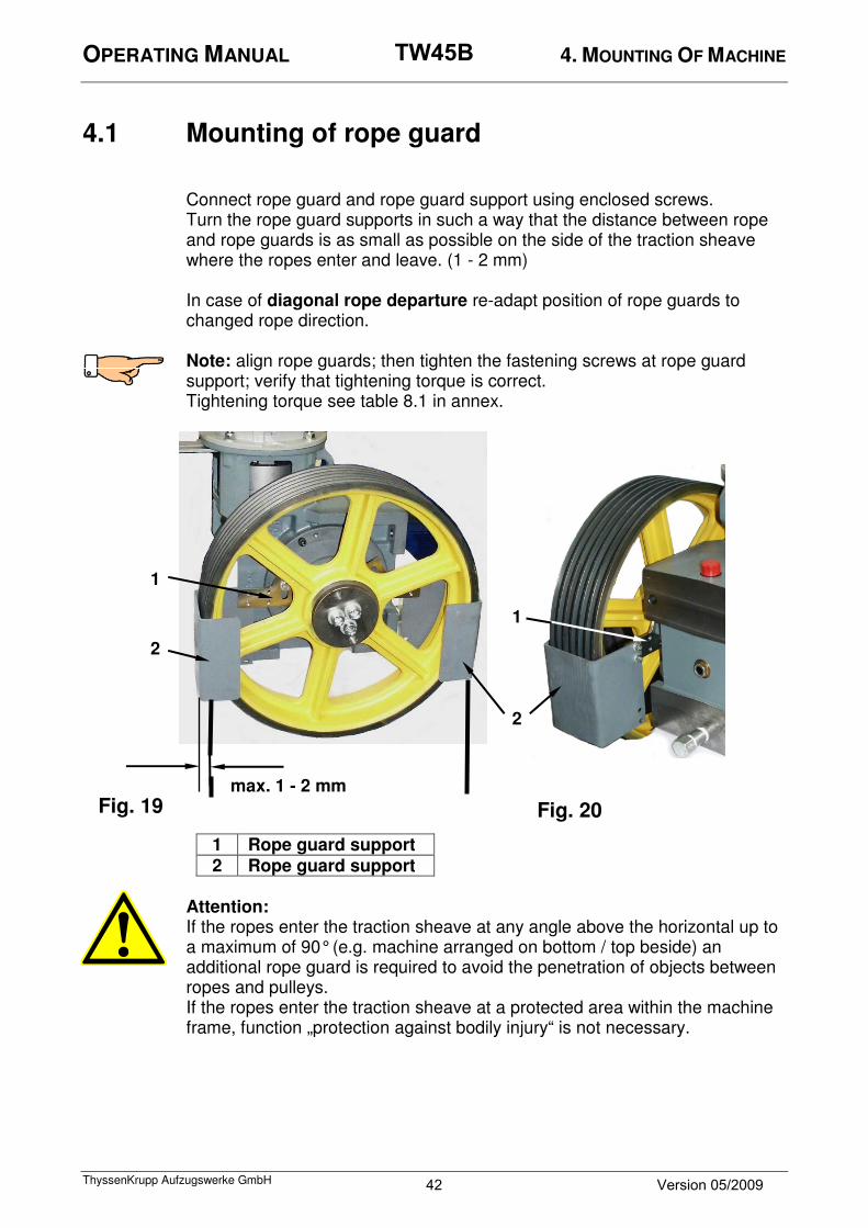
Connect rope guard and rope guard support using enclosed screws. Turn the rope guard supports in such a way that the distance between rope and rope guards is as small as possible on the side of the traction sheave where the ropes enter and leave. (1 - 2 mm) In case of diagonal rope departure re-adapt position of rope guards to changed rope direction. Note: align rope guards; then tighten the fastening screws at rope guard support; verify that tightening torque is correct. Tightening torque see table 8.1 in annex.
1 Rope guard support
2 Rope guard support
Attention: If the ropes enter the traction sheave at any angle above the horizontal up to a maximum of 90° (e.g. machine arranged on bottom / top beside) an additional rope guard is required to avoid the penetration of objects between ropes and pulleys. If the ropes enter the traction sheave at a protected area within the machine frame, function „protection against bodily injury“ is not necessary.
max. 1 - 2 mm
Fig. 19
1
1
2
2
Fig. 20
42 Version 05/2009
TW45B

OPERATING MANUAL 4. MOUNTING OF MACHINE
ThyssenKrupp Aufzugswerke GmbH
4.2 Connection
Motor connection: Observe terminal diagram at the cover of the motor connection box or terminal diagram in operating manual as well as the respective local requirements. Motor connection data see chapter 2.4 Technical data. Observe instructions of manufacturer in annex, chapter 8.6.
Fig. 21
1 2 3 4
9 8 7
6
5
1 W2
2 U2
3 Earth connection
4 V2
5 Posistor-temperature sensor
6 Posistor-temperature sensor
7 W1
8 V1
9 U1
43 Version 05/2009
TW45B

OPERATING MANUAL 4. MOUNTING OF MACHINE
ThyssenKrupp Aufzugswerke GmbH
Pulse encoder connection:
Connection and encoder data for encoder connection see chapters 8.3 – 8.5. Posistor- temperature sensor (motor – thermal element) connection:
To evaluate the posistor temperature sensor integrated in the motor a control unit (motor protection device) is required. This unit is to be connected to terminals in fig. 21, pos. 5 and 6. Holding brake for machine in machine room version (TWR), make Mayr:
The connecting line (approx. 1 m long) of the holding brake leaves the gear box at the gear flange side opposite the brake release levers. The magnet coils of the disc brake are to be connected to the black connecting line. The brake operates on a direct current supply. Polarity of the connecting coils (brown/blue) does not affect the way the brake operates. The coil voltage is indicated on the name plate.
Attention: there is the risk of wear when operating the brake at lower than intended connection voltage.
Further details see chapters 2.4 and 8.2.1
30 V!
30 V!
30 V!
44 Version 05/2009
TW45B

OPERATING MANUAL 4. MOUNTING OF MACHINE
ThyssenKrupp Aufzugswerke GmbH
Holding brake for machine in shaft (MRL) make Warner:
A 6 m long 4-core connecting line with socket at the line end is enclosed. This connector is to be connected to the connector at the connecting line. The two magnet coils are to be connected to the terminal block at the opposite line end. The line cores are identified each.
Cores 1 and 2 for magnetic coil C
Cores 3 and 4 for magnetic coil D
See fig. 26, pos. 19
The brake operates on a direct current supply. Polarity does not affect the way the brake operates. Correct coil voltage acc. to name plate.
Attention: verify that connecting voltage is correct. When operating the brake at lower than intended voltage the brake may fail to open completely. This may cause wear.
Further details see chapters 2.4 and 8.2.2 Note: there are two outputs for the brake coil connection to be able to operate each braking circuit individually. This is required for inspection by notified bodies (each brake circuit is tested separately or releasing the brakes step by step in cases of emergency such as rescue of passengers.
Attention: the drive is designed for installation in shaft and does not have any brake release levers. Please observe that the owner of the lift installation must ensure that the brake may be released step by step in case of power failure.
Emergency braking system NBS (optional) :
Description and details of emergency braking system see enclosed operating manual of NBS (if required).
Fig. 22
Coil C Coil D
Connector PHOENIX
6000
45 Version 05/2009
TW45B

OPERATING MANUAL 5. PUTTING INTO SERVICE
ThyssenKrupp Aufzugswerke GmbH
5.1 Putting into service
Before you start putting the machine into service the following works are to be performed:
• Check fastening of machine, traction sheave and frame
• Check whether rope guard is mounted and distance to traction sheave adjusted
• Check installation of machine, frame, base and rope departure
• Secure gear housing against moving in case of lateral or diagonal rope departure
• Tighten screws and secure with pre-set tightening torque (see table tightening torque 8.1)
• Check gear oil level
• Plastic plug in oil filling hole at gear housing removed and ventilation screw inserted and closed. Plastic plug at front side of housing removed and oil drain screw inserted and closed at height of traction sheave shaft (figures 14 to 16).
• Check supply terminals, earthing of motor, ventilation and brake magnets for correct connection and fusing
• Check connection (voltage, frequency) for compliance with manufacturer’s instructions
• Check monitoring devices (pulse generator, thermal element) for connection and correct functioning
• Check holding brake and emergency brake NBS (if available) for correct connection and functioning
• Check manual release of brake(s) for correct functioning (does not apply to machine in shaft)
• Check brake ventilation (for emergency evacuation, see chapter 1.2) mounted by the customer for correct functioning in case of machine in shaft (MRL)
• Visibly glue direction arrows (up/down) for respective travel direction at motor (adjacent to handwinding wheel)
• Remove safety, accessory and installation tools from danger zone Note: mount disassembled traction sheave using enclosed micro-encapsulated screws. See chapter 7.1 In case the machine is disassembled for reasons of weight, transport or space, re-assemble in original assembly condition and tighten fastening elements with respective tightening torque. See table tightening torque 8.1
Only use ThyssenKrupp Aufzugswerke mounting parts and components for installation and repairs. In case of disregard ThyssenKrupp Aufzugswerke GmbH cannot be hold liable.
46 Version 05/2009
TW45B
OPERATING MANUAL 5. PUTTING INTO SERVICE
ThyssenKrupp Aufzugswerke GmbH
5.2 Emergency operation
5.2.1 Drive with machine in machine room (TWR) without emergency
braking system NBS:
TW45B with machine in machine room is equipped with a handwinding wheel
and two brake release levers (one lever for each brake circuit).
When operating both brake release levers at the same time, the disc brake
opens.
To rescue passengers trapped in the car, it may be necessary to move the
car to the nearest landing by handwheel mechanism.
When the car is opened, the car may start suddenly dependent on the load.
Immediately stop turning the handwinding wheel and move the car by
carefully releasing the brake release levers (galloping brake).
Attention: persons operating the handwinding wheel (e. g. "lifting the car
from the moment of safety gear operation"), must work on a secure platform.
There is the risk of injury to persons when operating emergency operation
control at the same time.
5.2.2 Drive with emergency braking system NBS:
Note that emergency operation proceeding changes with emergency
braking system NBS mounted on.
Observe instructions in operating manual NBS!
Material No. of operating manual NBS: 65 990 01 86 0
Proceeding with emergency braking system see chapters 1.3 and 2.2!
5.2.3 Drive with machine in shaft and emergency braking system (machine-room-less variant without brake release levers attached and (optionally available) brake release levers
Corresponding counter measures are to be made by manufacturer of the elevator installation to be able to rescue passengers in the case of power failure.
Please note the following points:
• Carefully open the electrically operated brake
• Start car with weight of car / counterweight balanced and note that static friction of guides and automatic interlock of worm gear are to be overcome
• Check moving speed with the brakes open to avoid the risk of safety devices against overspeed being activated.
Further details on proceeding not possible as brake operation is subjected to respective design and version of elevator installation.
47 Version 05/2009
TW45B

OPERATING MANUAL 5. PUTTING INTO SERVICE
ThyssenKrupp Aufzugswerke GmbH
5.2.4 Optionally available brake release levers for manual release operation for drives equipped with tandem disc brakes from Warner (machine-room-less variant). Use of the lever mechanism necessitates the need of directly accessible drives. (e.g. machine in shaft pit)
1. Release of single brake: (e. g. manual brake test with one brake circuit
active)
Attach the narrow end pieces of the two brake release levers between
armature base plate and magnet coil carrier of brake. See fig. 23. Tighten both levers in direction of motor.
Fig. 23
48 Version 05/2009
TW45B

OPERATING MANUAL 5. PUTTING INTO SERVICE
ThyssenKrupp Aufzugswerke GmbH
2. Release of both brakes: (e. g. in case of emergency rescue)
Attach the two narrow end pieces of the release levers between armature
disc plate and magnet coil carriers at the brake. See fig. 24
Tighten both levers in direction of motor.
When operating both brake release levers at the same time, the two disc
brakes open.
Details on emergency rescue of trapped persons see proceeding in
chapter 5.2.1. Attention: remove brake release levers before the machine is switched on. Never start operation with the brake release levers attached!
Fig. 24
49 Version 05/2009
TW45B

OPERATING MANUAL 6. SERVICING
ThyssenKrupp Aufzugswerke GmbH
6.1 Servicing of machine
Servicing interval: servicing of the machine should be carried out at least once a year, preferably in the course of the general lift servicing.
Note: installation and servicing works shall only be carried out by trained and qualified personnel.
These persons must know and observe the respective regulations and requirements for lift installations as well as the accident prevention regulations.
For further information concerning proceeding, adjustment and data see chapter:
⇓⇓⇓⇓
• Check oil level and re-fill, if required 2.7
• Change oil at the end of oil change interval 2.7
• Clean ventilation screw and opening at gear housing 2.7
• Check gear and bearings for leakage
• Check brake and air gap (max. 1.7 mm with Mayr brake)
(max. 0.6 mm per air gap with Warner brake)
6.2
• Check holding brake and manual release for correct functioning 6.2
• Check brake deceleration 6.2
• Check worm toothing for wear
• Check circumferential flank clearance between worm shaft and
worm wheel; 0.05 mm to 0,12 mm at 20° C (max. 1.5 mm)
6.3
• Check traction sheave groove profile for damage and wear
• Check screws of traction sheave fastening for correct tightening 7.1 8.1
• Check machine, supports and rope pulley supports for correct
fastening with machine mounted on machine
2.5
• Check grooves of rope pulleys for damage and wear
• Check electrical connections for correct functioning and test for
safety
4.2
• Check protective and safety equipment and test for correct
functioning and adjustment
Notes on lubrication (oil change, quantity, oil change interval) see chapter 2.7
50 Version 05/2009
TW45B

OPERATING MANUAL 6. SERVICING
ThyssenKrupp Aufzugswerke GmbH
6.2 Checking of drive brake
Inspection interval: once a year in the course of the general lift servicing 1.) Functional test of holding brake
electrical test: power supply off ⇒ brake closed
power supply on ⇒ brake released mechanical test (only possible in case of machine in machine room (TWR):
press both release levers ⇒ brake released press each release lever
separately ⇒ brake closed When the brake opens, the armature disc moves away from the friction disc, and the air gap is closed. See fig. 24 / 26 2.) Inspection of wearing condition:
Wear at the friction linings of the rotor is caused by improper setting or defects. When wearing limit is reached, replace friction linings or disc brake.
Inspection of wearing condition by checking the air gap:
The maximum permissible air gap is:
1.7 mm for Mayr brake (TWR version)
2 x 0.6 mm for Warner brake (MRL version) Description of the inspection sequence see 7.2 3.) Inspection of deceleration
a) Test of one single brake circuit. To check the brake circuits for correct operation each brake circuit must be inspected separately. The brake shall be checked with one brake circuit effective only. Note: holding brake of lifts equipped with an emergency braking system
NBS can only be checked with the emergency braking system NBS out of service ! Description see operating manual Emergency braking system NBS.
51 Version 05/2009
TW45B
OPERATING MANUAL 6. SERVICING
ThyssenKrupp Aufzugswerke GmbH
Before testing:
• Inspection signs must be made available at the landing doors during inspection work at the lift.
• Close the doors acc. to the rules.
• Make sure that the car is empty.
• The car must be at least two landings below respective terminal landing (seen from run direction).
Car empty þ run direction up;
Car loaded with rated load þ run direction down.
• The single brake circuits are tested by energizing the single brake coils with 90 V / 45 V excitation / withstand voltage.
When a single circuit is tested, the brake of the 2. brake circuit must be released during the braking process. Therefore, the magnet coil of the 2. brake circuit is energized with withstand voltage.
Attention: should the lift move after release of one brake circuit or not decelerate sensibly during the braking process, the energized coil must be switched off immediately. The dual circuit braking function is not guaranteed. Check brake !
Test sequence: inspection of the brake deceleration to be made for each brake circuit individually
• Connect deceleration measuring device
• Activate normal run (brake to be tested is released)
• Activate emergency stop as soon as rated speed is reached (brake to be tested closes)
• Determine deceleration for 1. brake circuit using a measuring device
• Compare result of the measurement and reference value
• Remove continuous voltage supply at continuously open 2. brake circuit and connect to 1. brake circuit.
• Connect test terminal at deceleration measuring device to 2. brake circuit.
• Repeat test at 2. brake circuit. Deceleration values:
Minimum deceleration for one brake circuit 0.4 m/s²
Minimum deceleration for both brake circuits 1.0 m/s²
Attention: when the single brake test is terminated, the continuous control voltage at the 2. brake is to be removed, and the original condition established (operation of both brakes).
52 Version 05/2009
TW45B
OPERATING MANUAL 6. SERVICING
ThyssenKrupp Aufzugswerke GmbH
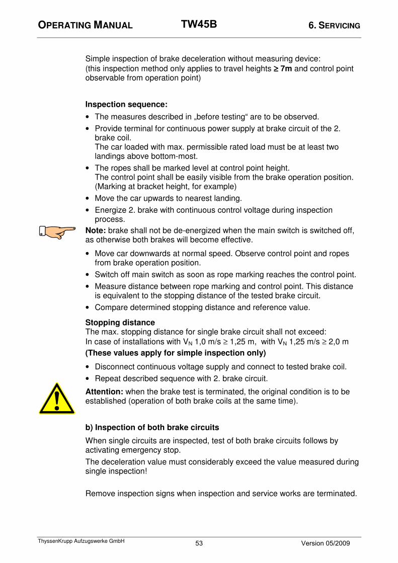
Simple inspection of brake deceleration without measuring device:
(this inspection method only applies to travel heights ≥≥≥≥ 7m and control point observable from operation point)
Inspection sequence:
• The measures described in „before testing“ are to be observed.
• Provide terminal for continuous power supply at brake circuit of the 2. brake coil. The car loaded with max. permissible rated load must be at least two landings above bottom-most.
• The ropes shall be marked level at control point height. The control point shall be easily visible from the brake operation position. (Marking at bracket height, for example)
• Move the car upwards to nearest landing.
• Energize 2. brake with continuous control voltage during inspection process.
Note: brake shall not be de-energized when the main switch is switched off, as otherwise both brakes will become effective.
• Move car downwards at normal speed. Observe control point and ropes from brake operation position.
• Switch off main switch as soon as rope marking reaches the control point.
• Measure distance between rope marking and control point. This distance is equivalent to the stopping distance of the tested brake circuit.
• Compare determined stopping distance and reference value.
Stopping distance The max. stopping distance for single brake circuit shall not exceed:
In case of installations with VN 1,0 m/s ≥ 1,25 m, with VN 1,25 m/s ≥ 2,0 m
(These values apply for simple inspection only)
• Disconnect continuous voltage supply and connect to tested brake coil.
• Repeat described sequence with 2. brake circuit.
Attention: when the brake test is terminated, the original condition is to be established (operation of both brake coils at the same time).
b) Inspection of both brake circuits
When single circuits are inspected, test of both brake circuits follows by activating emergency stop.
The deceleration value must considerably exceed the value measured during single inspection!
Remove inspection signs when inspection and service works are terminated.
53 Version 05/2009
TW45B
OPERATING MANUAL 6. SERVICING
ThyssenKrupp Aufzugswerke GmbH
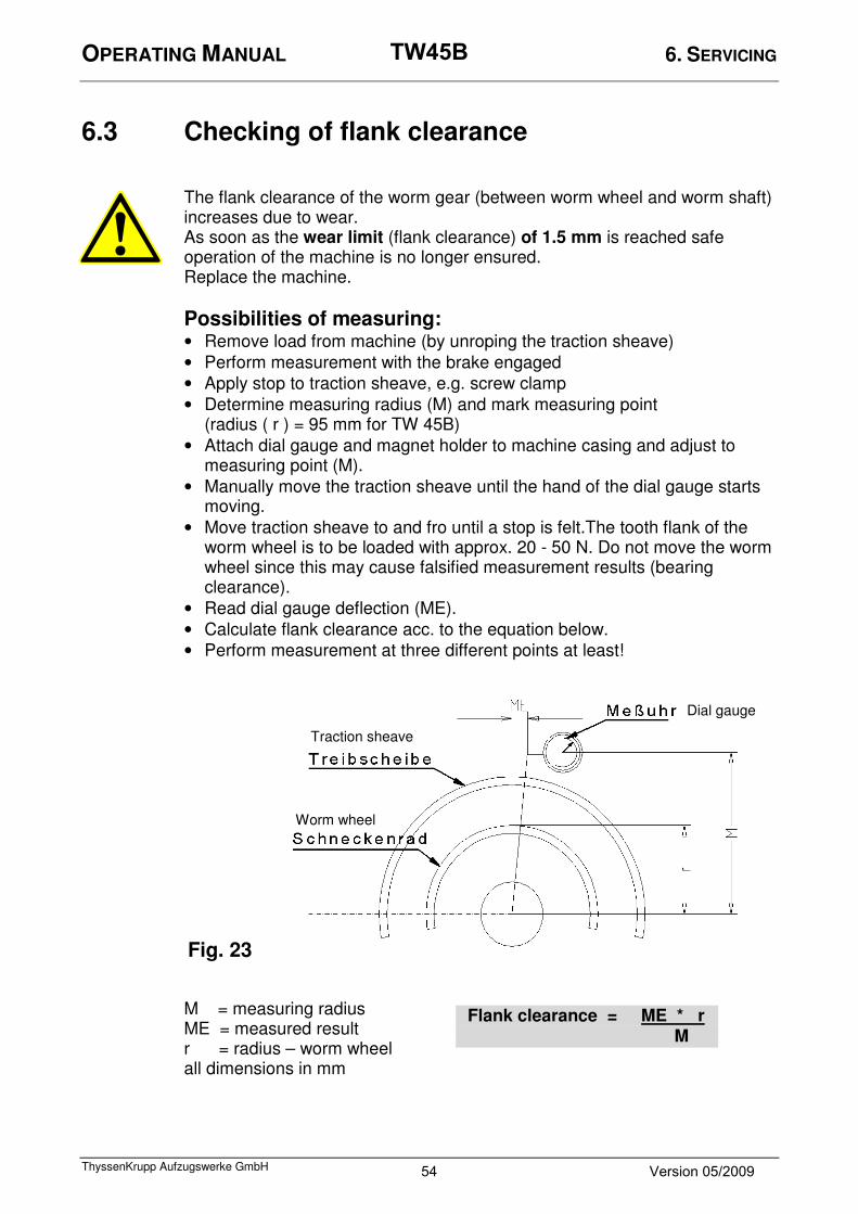
6.3 Checking of flank clearance
The flank clearance of the worm gear (between worm wheel and worm shaft) increases due to wear. As soon as the wear limit (flank clearance) of 1.5 mm is reached safe operation of the machine is no longer ensured. Replace the machine.
Possibilities of measuring:
• Remove load from machine (by unroping the traction sheave)
• Perform measurement with the brake engaged
• Apply stop to traction sheave, e.g. screw clamp
• Determine measuring radius (M) and mark measuring point (radius ( r ) = 95 mm for TW 45B)
• Attach dial gauge and magnet holder to machine casing and adjust to measuring point (M).
• Manually move the traction sheave until the hand of the dial gauge starts moving.
• Move traction sheave to and fro until a stop is felt.The tooth flank of the worm wheel is to be loaded with approx. 20 - 50 N. Do not move the worm wheel since this may cause falsified measurement results (bearing clearance).
• Read dial gauge deflection (ME).
• Calculate flank clearance acc. to the equation below.
• Perform measurement at three different points at least!
M = measuring radius ME = measured result r = radius – worm wheel all dimensions in mm
Flank clearance = ME * r
M
Dial gauge
Traction sheave
Worm wheel
Fig. 23
54 Version 05/2009
TW45B

OPERATING MANUAL 6. MAINTENANCE/ SERVICE
ThyssenKrupp Aufzugswerke GmbH
6.4 Checking for escaping grease / oil
Examine the areas around the brake disc and armature base plate for traces of oil.
Contamination level Procedure No escaping oil determined Check regularly within the
framework of maintenance Every 3 months (6 months if elevator used infrequently, < 50 000 runs per year)
If a large amount of escaping oil is determined or oil is escaping from the brake disc / brake linings
Clean the drive and, if necessary, the brake and carry out short-term repairs Before continuing operation until modification, run a brake test. If the braking effect is inadequate, shut down the installation.
Repair after 4 weeks at the latest
55 Version 05/2009
TW45B

OPERATING MANUAL 6. MAINTENANCE/ SERVICE
ThyssenKrupp Aufzugswerke GmbH
��Diagram of the horizontal version ������� ���������������� Fig. 6.4.1
ÖÖÖÖLLLL
FettFettFettFett�
�
�
Brake discs
Armature base plates
Bearing cover Shaft sealing ring
56 Version 05/2009
TW45B

OPERATING MANUAL 7. MAINTENANCE
ThyssenKrupp Aufzugswerke GmbH
7.1 Replacing of traction sheave - installation
Disassembly:
• Switch off power supply, secure car and counterweight.
• Remove rope guard plates.
• Remove load from traction sheave; discard ropes.
• Secure traction sheave with lifting device.
• Loosen screws on mounting disc of traction sheave; put screws in outer hole circle of disk and loosely screw in traction sheave hub.
• Place a washer approx. 5 – 10mm thick between shaft end and disk.
• Tlighten screws uniformly and remove traction sheave from motor shaft.
Assembly:
• Clean shaft end and traction sheave holes; never make any dimensional changes in featherkey, groove, shaft or drilled holes. Check whether the contact surfaces are free from visible damage.
• Never grease or oil shaft and holes.
• Carefully fit and screw new traction sheave to conical end of motor wheel shaft.
• Bring position of featherkey and groove in line.
• Push traction sheave on motor shaft.
• Screw-connect disk at inner hole circle using enclosed screws (micro-encapsulated) and detent edged washers. Tighten screws uniformly in several operations.
Attention danger: the traction sheave may work loose if assembled improperly.
• Observe screw strength 8.8 and tightening torque = 75 Nm !
• Remove securing devices at traction sheave with lifting device
• Replace ropes
• Mount and align rope guard plates
• Remove securing devices at car and counterweight
1
1 Fastening screws
2 Forcing screw / hole
3 Traction sheave
4 Mounting disk
5 Rope guard plate
2 3 4
5 2 5
Fig. 24
57 Version 05/2009
TW45B
OPERATING MANUAL 7. MAINTENANCE
ThyssenKrupp Aufzugswerke GmbH
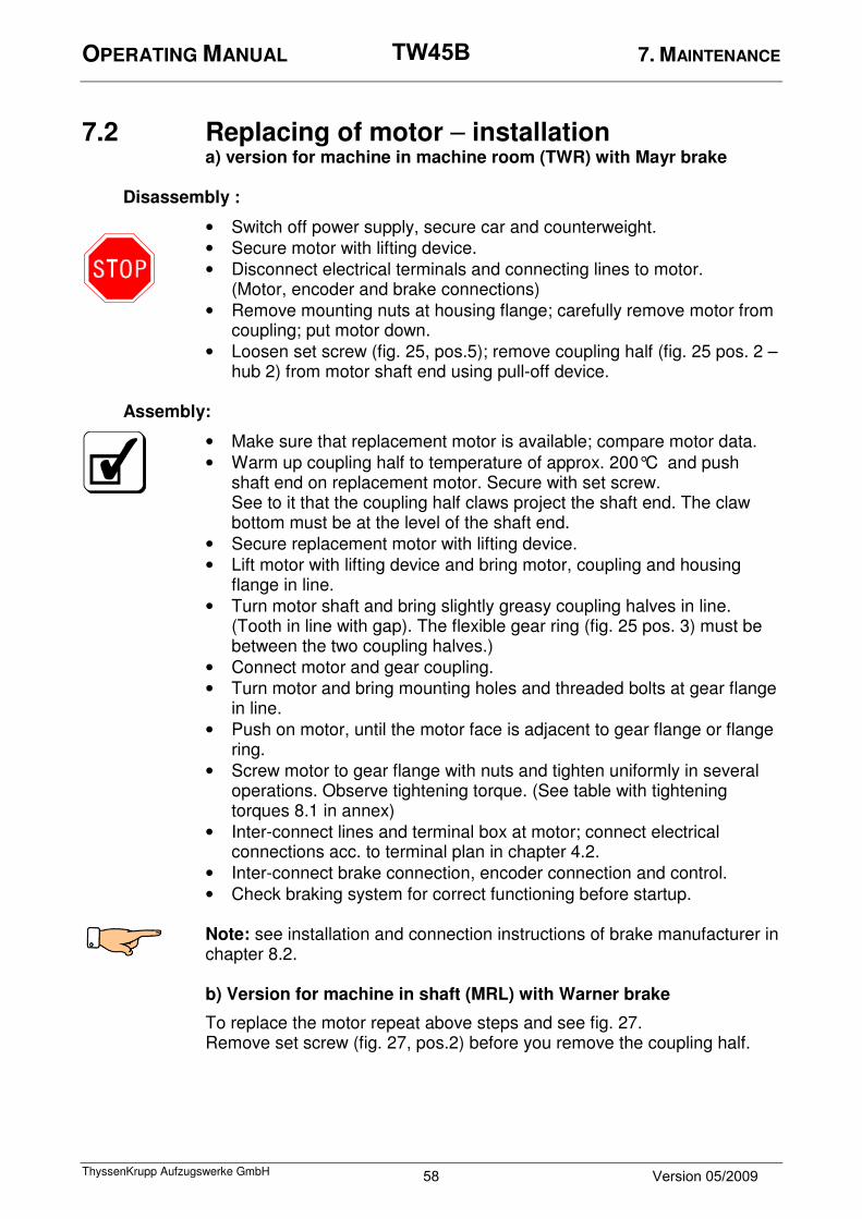
7.2 Replacing of motor – installation a) version for machine in machine room (TWR) with Mayr brake
Disassembly :
• Switch off power supply, secure car and counterweight.
• Secure motor with lifting device.
• Disconnect electrical terminals and connecting lines to motor. (Motor, encoder and brake connections)
• Remove mounting nuts at housing flange; carefully remove motor from coupling; put motor down.
• Loosen set screw (fig. 25, pos.5); remove coupling half (fig. 25 pos. 2 –hub 2) from motor shaft end using pull-off device.
Assembly:
• Make sure that replacement motor is available; compare motor data.
• Warm up coupling half to temperature of approx. 200°C and push shaft end on replacement motor. Secure with set screw. See to it that the coupling half claws project the shaft end. The claw bottom must be at the level of the shaft end.
• Secure replacement motor with lifting device.
• Lift motor with lifting device and bring motor, coupling and housing flange in line.
• Turn motor shaft and bring slightly greasy coupling halves in line. (Tooth in line with gap). The flexible gear ring (fig. 25 pos. 3) must be between the two coupling halves.)
• Connect motor and gear coupling.
• Turn motor and bring mounting holes and threaded bolts at gear flange in line.
• Push on motor, until the motor face is adjacent to gear flange or flange ring.
• Screw motor to gear flange with nuts and tighten uniformly in several operations. Observe tightening torque. (See table with tightening torques 8.1 in annex)
• Inter-connect lines and terminal box at motor; connect electrical connections acc. to terminal plan in chapter 4.2.
• Inter-connect brake connection, encoder connection and control.
• Check braking system for correct functioning before startup.
Note: see installation and connection instructions of brake manufacturer in chapter 8.2. b) Version for machine in shaft (MRL) with Warner brake
To replace the motor repeat above steps and see fig. 27. Remove set screw (fig. 27, pos.2) before you remove the coupling half.
58 Version 05/2009
TW45B

OPERATING MANUAL 7. MAINTENANCE
ThyssenKrupp Aufzugswerke GmbH
7.3 Replacing of brake with machine room version (TWR)
Replacing of dual-circuit disk brake (Mayr)
To replace brake proceed as follows:
• Remove motor as described in chapter 7.2
• Disconnect connecting cable (19)
• Remove screws (16), remove release levers (14) and (15)
• Remove gear ring (3)
• Remove screws (11), pull off brake
1 Hub 1 11 Cheese-head screw (4x)
2 Hub 2 12 Pressure spring (4x)
3 Gear ring 13 Pressure spring (4x)
4 Set screw 14 Release lever 1
5 Set screw 15 Release lever 2
6 O ring 16 Cheese-head screw (4x)
7 Coil carrier with magnet coil 17 Cheese-head screw (2x)
8 Two-piece armat.base plate 18 Damping elements (6x)
9 Rotor 19 Connect. cable appr. 1m long
10 Socket (4x) 20 Screw
Air gap Fig. 25
Measure
59 Version 05/2009
TW45B

OPERATING MANUAL 7. MAINTENANCE
ThyssenKrupp Aufzugswerke GmbH
• Loosen set screw (4), remove hub with rotor (9) from worm shaft
• Put hub 1 of new brake with mounted rotor onto worm shaft end (note mounting direction)
Attention: mechanical impacts onto the worm shaft will damage the rolling bearings.
• To assemble brake, repeat steps in reverse order
• Mount motor with mounted hub at drive, connect connections
See to it that:
• Tightening torque of screws fig. 25 pos. 11 : 22 Nm
• Tightening torque of screws fig. 25 pos. 16 : 6 Nm
• Secure screws (16) with Loctite 213
• Check air gap
• Check brake release (the rotor must be able to be turned in an energized condition of the brake free of brake torque using the handwinding wheel, fig. 26 pos. 2)
Note: the emergency braking device NBS must be released during testing. Screw release screws at NBS in. See operating manual NBS.
Air gap check: put a feeler gauge between armature disc (3) and magnet coil carrier (4) and check air gap (7). Repeat several times at the circumference. The brake magnets must be de-energized. (Brake de-energized).
The air gap of new linings should be 0.35-0.45 mm. See 6.2 Checking of drive brake
1 Gear housing
2 Rotor with brake linings
3 Armature disk
4 Magnet coil carrier
5 Brake release lever
6 Motor flange
7 Air gap
Fig. 26
5 4 6
7
2 3 1
60 Version 05/2009
TW45B

OPERATING MANUAL 7. MAINTENANCE
ThyssenKrupp Aufzugswerke GmbH
7.4 Replacing of brake with shaft version (MRL)
Brake (from Warner) without brake release levers and 2 rotors
1 Motor shaft 12 Rotor 2
2 Set screw 13 Bearing cover
3 Coupling half 14 Cheese-head screw (4x)
4 Armature disk D 15 Shaft sealing ring
5 Magnet coil carrier D 16 Gear housing
6 Cheese-head screw (3x) 17 O ring (3x)
7 Motor flange 18 Worm shaft
8 Flange ring 19 Brake connection
9 Rotor 1 20 Retaining washer
10 Magnet coil carrier C 21 Coupling hub
11 Armature disc C 22 Flexible gear ring
Air gap at coil carriers
1
7
5
6
8
4
3
2
9 10 11 12 13 14 15
17 18
Fig. 27
19 20
16
22 21
61 Version 05/2009
TW45B

OPERATING MANUAL 7. MAINTENANCE
ThyssenKrupp Aufzugswerke GmbH
Do not perform any work at the brake without observing the instructions of the manufacturer in chapter 8.2.2. Note: when the air gap reaches the maximum value (0.6 mm/gap) or the brake is defective, it must be completely replaced. Disassembly:
• Switch off power supply and secure drive against unintentional switching on; secure car and counterweight
• Disconnect brake and motor connections; remove motor
• Remove flexible coupling
• Remove retaining washer at worm shaft front (pos. 20)
• Secure brake package using enclosed lockings screws. The respective mounting holes are in the hole circle of the fastening screws.
Attention: before you loosen the fastening screws, secure brake unit with enclosed two screws M6 x 80 K8 with red screw head. Highly pre-tensioned pressure springs are installed between armature base plate and coil carrier. These parts may burst in case the brake unit is not secured.
• Unscrew cheese-head screws pos. 6.
• Remove secured brake unit incl. coupling hub from worm shaft (pos. 18) using pull-off device screw-connected to front coupling hub by two M5 screws.
Assembly:
• Pull new brake unit up onto worm shaft. Align borings with the brake energized (electrically released).
• Bring fastening screws and thread in bearing cover in line and loosely screw.
• Screw-connect coupling hub and worm shaft using retaining washer pos. 20, cheese-head screw M12 x 25 8.8 and retaining ring. (75 Nm)
• Lock fastening screws pos. 6 with Loctite 243 and tighten with required tightening torque. (9 Nm)
• Remove locking screws for brake assembly.
• Put flexible gear ring in coupling hub.
• Mount motor to gear housing; bring motor coupling and brake in line by turning the motor shaft.
• Tighten motor fastening screws, connect brake and motor. Check air gap between magnet coil carrier and armature base plates. Repeat several times at the circumference. Attention: check brake for correct functiong before it is released for lift operation.
62 Version 05/2009
TW45B
OPERATING MANUAL 8. ANNEX
ThyssenKrupp Aufzugswerke GmbH
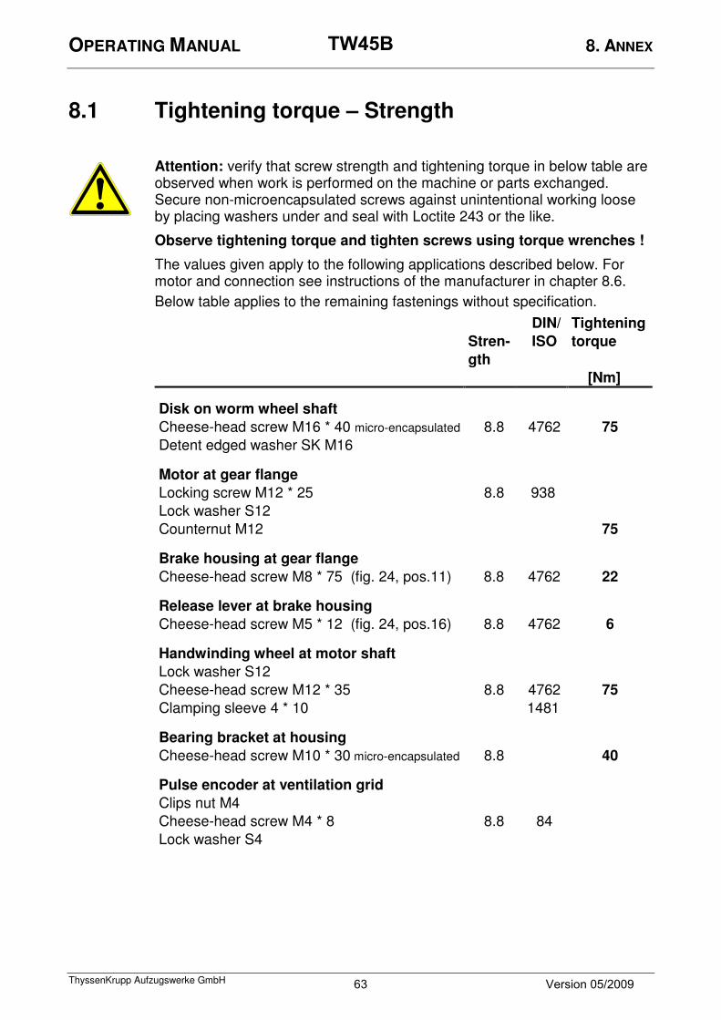
8.1 Tightening torque – Strength
Attention: verify that screw strength and tightening torque in below table are observed when work is performed on the machine or parts exchanged. Secure non-microencapsulated screws against unintentional working loose by placing washers under and seal with Loctite 243 or the like.
Observe tightening torque and tighten screws using torque wrenches !
The values given apply to the following applications described below. For motor and connection see instructions of the manufacturer in chapter 8.6.
Below table applies to the remaining fastenings without specification.
DIN/ Tightening
Stren-
gth
ISO torque
[Nm]
Disk on worm wheel shaft
Cheese-head screw M16 * 40 micro-encapsulated 8.8 4762 75
Detent edged washer SK M16
Motor at gear flange
Locking screw M12 * 25 8.8 938
Lock washer S12
Counternut M12 75
Brake housing at gear flange
Cheese-head screw M8 * 75 (fig. 24, pos.11) 8.8 4762 22
Release lever at brake housing
Cheese-head screw M5 * 12 (fig. 24, pos.16) 8.8 4762 6
Handwinding wheel at motor shaft
Lock washer S12
Cheese-head screw M12 * 35 8.8 4762 75
Clamping sleeve 4 * 10 1481
Bearing bracket at housing
Cheese-head screw M10 * 30 micro-encapsulated 8.8 40
Pulse encoder at ventilation grid
Clips nut M4
Cheese-head screw M4 * 8 8.8 84
Lock washer S4
63 Version 05/2009
TW45B

OPERATING MANUAL 8. ANNEX
ThyssenKrupp Aufzugswerke GmbH
Cheese-head screws ISO 4762 (DIN 912) Hexagon bolts ISO 4014 / 4017 (DIN 931 / 933)
Dimension Tightening torque MA (Nm)
Strength 8.8 10.9 12.9
M4 2,6
M5 5,3
M6 9 12 15
M8 23 30 35
M10 45 60 75
M12 75 110 130
M16 190 270 320
M20 370 520 620
M24 640 900 1100
Note: use micro-encapsulated screws once only.
Only use mounting parts and components from ThyssenKrupp Aufzugswerke GmbH. In case of disregard ThyssenKrupp Aufzugswerke GmbH cannot be hold liable.
64 Version 05/2009
TW45B

OPERATING MANUAL 8. ANNEX
ThyssenKrupp Aufzugswerke GmbH
8.2 Blocking clamp
Each machine is equipped with a blocking clamp corresponding to the respective traction sheave (rim width and design)
Use of blocking clamp:
Use the rope clamp to secure the ropes and prevent rope slip or secure the car / counterweight (release from safety gear operation). Note: install the two-piece rope clamp on the ropes. Clamp and tighten clamp screwing accordingly.
Rope clamp mounting at traction sheave
1 Traction sheave
2 Ropes
3 Pressure piece
4 Washer
5 Hexagon nut
6 Spacer
7 Clamp clip
Attention: remove blocking clamp when installation works are terminated. Disregard will damage the installation.
5
6
7 2
3
4
1
Fig. 28
65 Version 05/2009
TW45B


6000

Overview: the following encoders are available for TW45B 1. 1024 - (standard version) / 4096 - TTL (optional)
for v < 1.5 m/s with 1024 pulses material number 9950 000 6021
for v ≥ 1.5 m/s with 4096 pulses material number 9950 000 6022 Use cable of 10 m length, SUB-D 9 tab and locking lever acc. to DIN 46342 for connection Connector assignment Electrical data: Connection Pin Colour Power supply: 5 V DC
Minus 7 white Power consumpt.: max. 60 mA Plus 9 brown Output: push-pull Channel A 2 green Load: max. 40 mA Channel B 3 yellow Signal level at 20 mA:
H > 3.6 VDC
Zero pulse 5 grey L < 1.2 VDC Channel A inv. 1 red Pulse frequency: max. 200 kHz Channel B inv. 4 black Circuit protection: no Zero pulse inv. 6 violet Shield 8+housing black
Please note instructions of the manufacturer in chapters 8.4 – 8.5
2. 1024 HTL (optional)-
with 1024 pulses material number 00 990 16 03 0
Connection by insulated cable of 10 m length with end sleeves. Connector assignment Electrical data: Connection Colour Power supply: 10 - 30 V DC
Channel A green Power consump.: max. 60 mA Channel B yellow Channels: A, B, N, ABN inv. Channel N grey Output: HTL- differential driver Channel A inv. red Load: max. 40 mA Channel B inv. black Signal level: at 20 mA
Channel N inv. violet H > UB – 2,5 VDC
Mass yellow L > 2,5 VDC Plus 15 V brown Pulse frequency: max. 200 kHz Minus white Circuit protection:: yes Shield cord Control output: NPN OC, 10 mA Control output: rose Umax. = 30 VDC Cable length: max. 10 m Longer cables available. Please contact manufacturer.
Please note instructions of the manufacturer in chapters 8.4 – 8.5

3. 1024 – Sine / Cosine - HTL (optional)-
with 1024 pulses material number 00 990 19 03 0
Connection by insulated cable of 10 m length with end sleeves.
Connector assignment Electrical data: Connection Colour Power supply: 4.75– 5.5 V DC
Channel +A green Power consump.: max. 100 mA Channel +B grey without load Channel +N black Channels / output: sine, cosine, N Channel - A yellow Output load: min 120 Ohm Channel - B rose Terminal resistor between + and Channel - N violet - outputs. Plus 5 V brown Signal level: 1 Vss +/- 25 % Minus white Max. frequency (-3dB): 100 kHz Shield cord Circuit protection: no
Control output: conductive when defective
Cable length: max. 150m at <260pF/m Design acc. to DIN VDE 0160
Please note instructions of the manufacturer in chapters 8.4 – 8.5

Part No. 9950 000 6021 mit 1024 Imp.
Part No. 9950 000 6021 mit 4096 Imp.

Part No. 00 990 16 03 0 with 1024 pulses

Part No. 00 990 19 03 0 mit 1024 Imp.
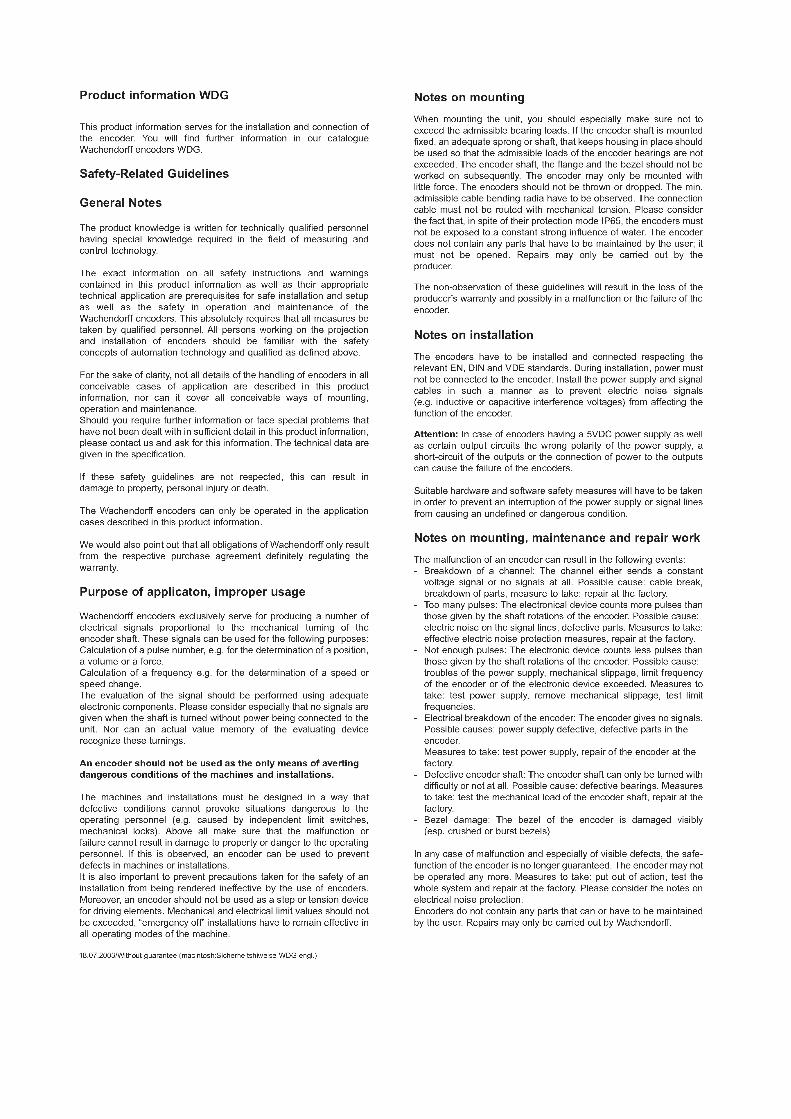

ThyssenKrupp Aufzugswerke GmbH
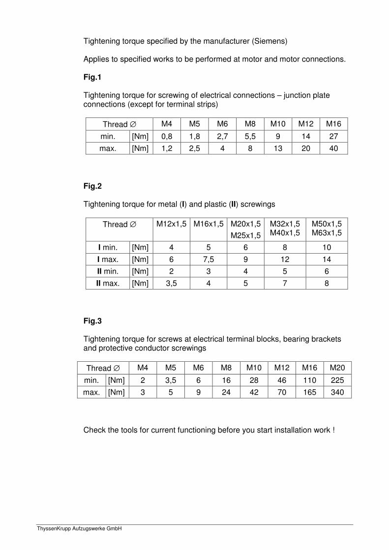
ThyssenKrupp Aufzugswerke GmbH
Tightening torque specified by the manufacturer (Siemens) Applies to specified works to be performed at motor and motor connections. Fig.1
Tightening torque for screwing of electrical connections – junction plate connections (except for terminal strips)
Thread ∅ M4 M5 M6 M8 M10 M12 M16
min. [Nm] 0,8 1,8 2,7 5,5 9 14 27
max. [Nm] 1,2 2,5 4 8 13 20 40
Fig.2
Tightening torque for metal (I) and plastic (II) screwings
Thread ∅ M12x1,5 M16x1,5 M20x1,5
M25x1,5
M32x1,5 M40x1,5
M50x1,5 M63x1,5
I min. [Nm] 4 5 6 8 10
I max. [Nm] 6 7,5 9 12 14
II min. [Nm] 2 3 4 5 6
II max. [Nm] 3,5 4 5 7 8
Fig.3
Tightening torque for screws at electrical terminal blocks, bearing brackets and protective conductor screwings
Thread ∅ M4 M5 M6 M8 M10 M12 M16 M20
min. [Nm] 2 3,5 6 16 28 46 110 225
max. [Nm] 3 5 9 24 42 70 165 340
Check the tools for current functioning before you start installation work !


Issu
e 0
5/20
09
Nr.
62 3
10 0
3 86
0 ThyssenKrupp Aufzugswerke GmbH
Ein Unternehmen von ThyssenKrupp Elevator Bernhäuser Strasse 45 73765 Neuhausen a. d. F. Deutschland Tel.: +49 7158/12-0 Fax: +49 7158/12-2585 E-Mail: [email protected] www.thyssenkrupp-aufzuege.de


