TVSS Lightning and Equipment Protection
28
TVSS Lightning and Equipment Protection Presented by Scott Peele PE
Transcript of TVSS Lightning and Equipment Protection

TVSS Lightning and Equipment Protection
Presented by
Scott Peele
PE

TVSS Lightning and Equipment Protection
What is a Surge or Lightning.Coupling on the electrical systemUnderstanding TVSS or SPD protectionGrounding for LightningRecommended Practices
What is a Surge?
A surge is a TransientA Transient can be classified into two categories, impulsive and oscillatory

Impulsive
This is the category that TVSS (Transient Voltage Surge Suppressor) SPD Surge Protection Device) equipment is designed to mitigate.
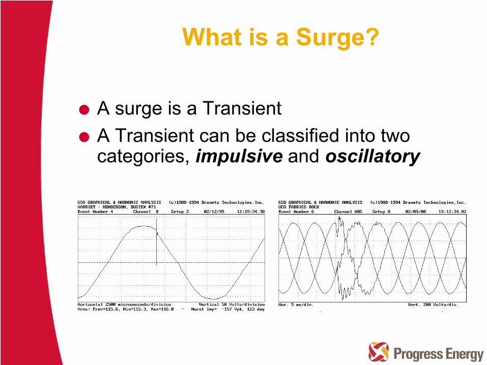
Sources of Transients
LightningStaticArc Welding
SwitchingcontactorrelaysSCR’s
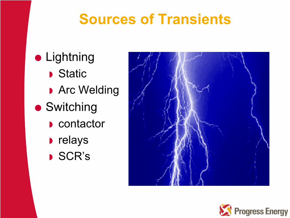
Key# of cloud to ground flashes per sq kM/year
1989-93 Ave Lightning Flash Density
http://Lightning Detection Network
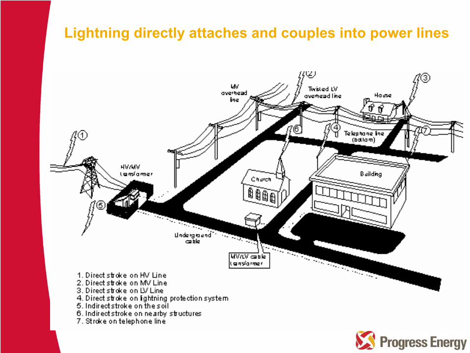
Lightning directly attaches and couples into power lines
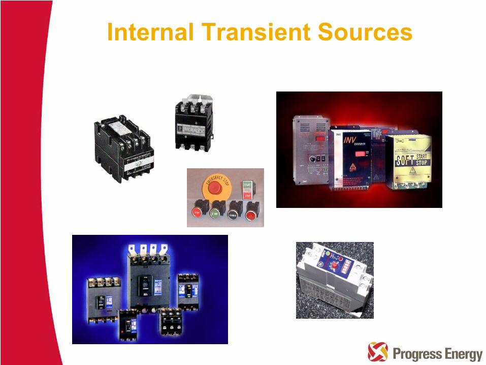
Internal Transient Sources

A B C
UndergroundService Connection
OverheadServiceConnection
A B C
IEEE C62.41 Cat. CIEEE C62.62IEEE C62.1/11
IEEE C62.41 Cat. BIEEE C62.62UL 1449
IEEE C62.41 Cat. AIEEE C62.62UL 1449
Applicable Standards for surge protection at locations A, B and C
Location Exposure Categories for Surge

0.001
0.01
0.1
0.5
1.0
61030
100
1000
10000
Cycles
Transient Suppressor Protection Relative Performance
106%87%
NominalVoltage
1
2
10
100
Seconds
300
200
100
0
Typical Energy Limitsof Suppressor
Clamping Level Determinedby Energy in Impulse andImpedance of Source
Lower Clamping Limit
Percent of NominalVoltage
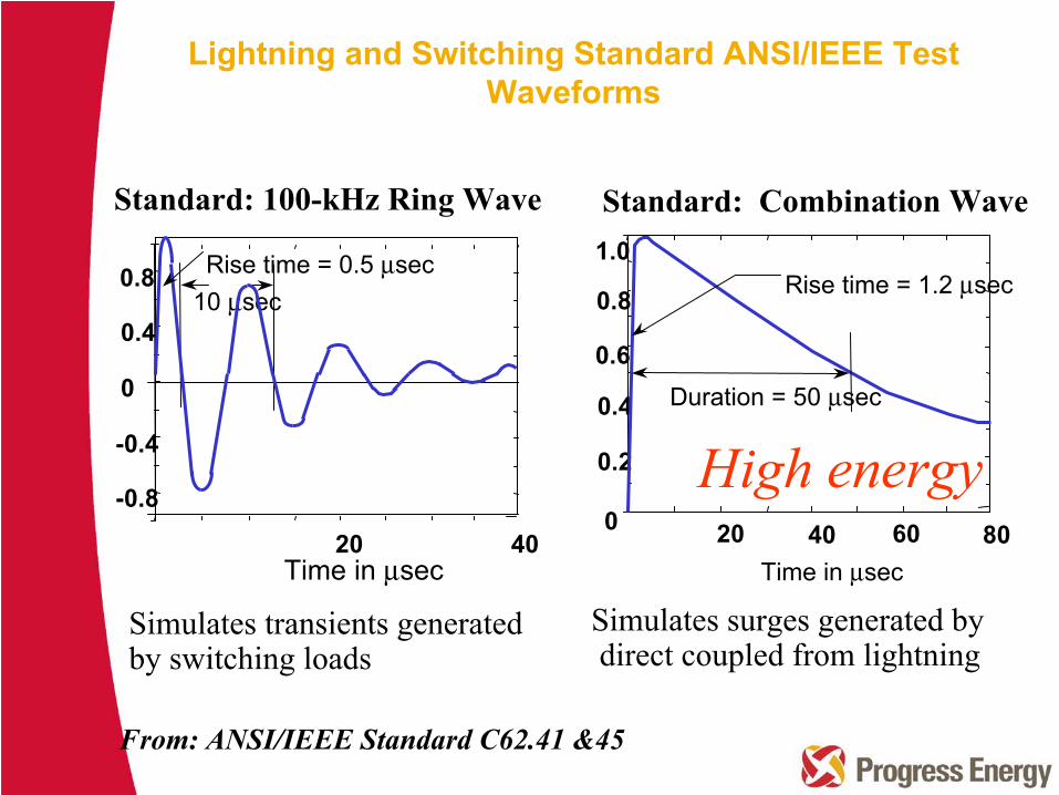
Standard: 100-kHz Ring Wave Standard: Combination Wave
Simulates transients generated by switching loads
0
0.2
0.4
0.6
40 80
0.8 Rise time = 1.2 μsec
Duration = 50 μsec
Time in μsec20 60
1.0
-0.8
-0.4
0
0.4
20 40
0.8 Rise time = 0.5 μsec10 μsec
Time in μsec
Simulates surges generated bydirect coupled from lightning
From: ANSI/IEEE Standard C62.41 &45
High energy
Lightning and Switching Standard ANSI/IEEE Test Waveforms
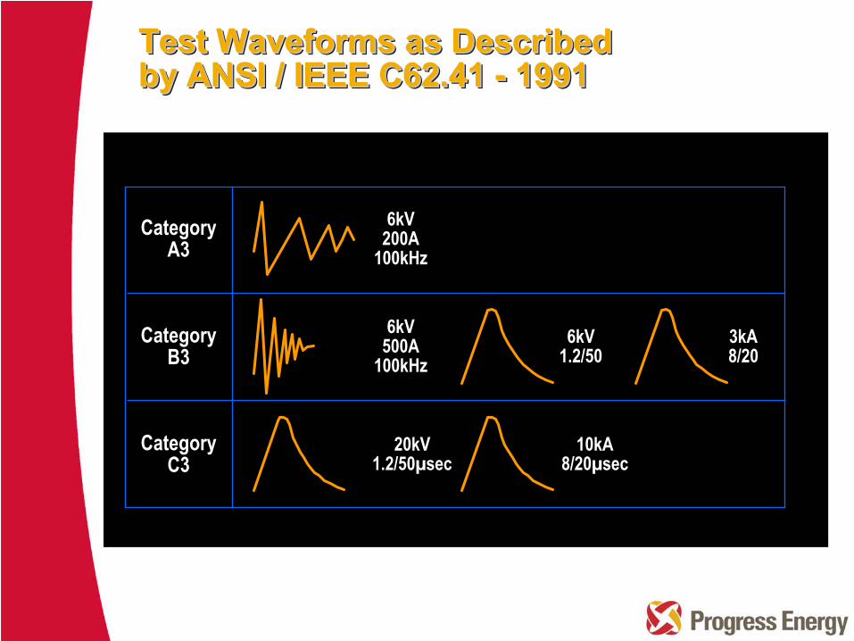
CategoryA3
CategoryB3
CategoryC3
6kV200A
100kHz
6kV500A
100kHz6kV
1.2/503kA8/20
20kV1.2/50µsec
10kA8/20µsec
Test Waveforms as Described by ANSI / IEEE C62.41 -
1991
Test Waveforms as Described Test Waveforms as Described by ANSI / IEEE C62.41 by ANSI / IEEE C62.41 --
19911991
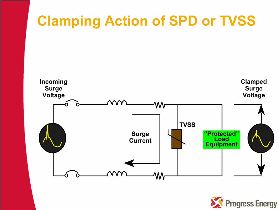
SurgeCurrent
TVSS
ClampedSurge
Voltage
“Protected”Load
Equipment
IncomingSurge
Voltage
Clamping Action of SPD or TVSS
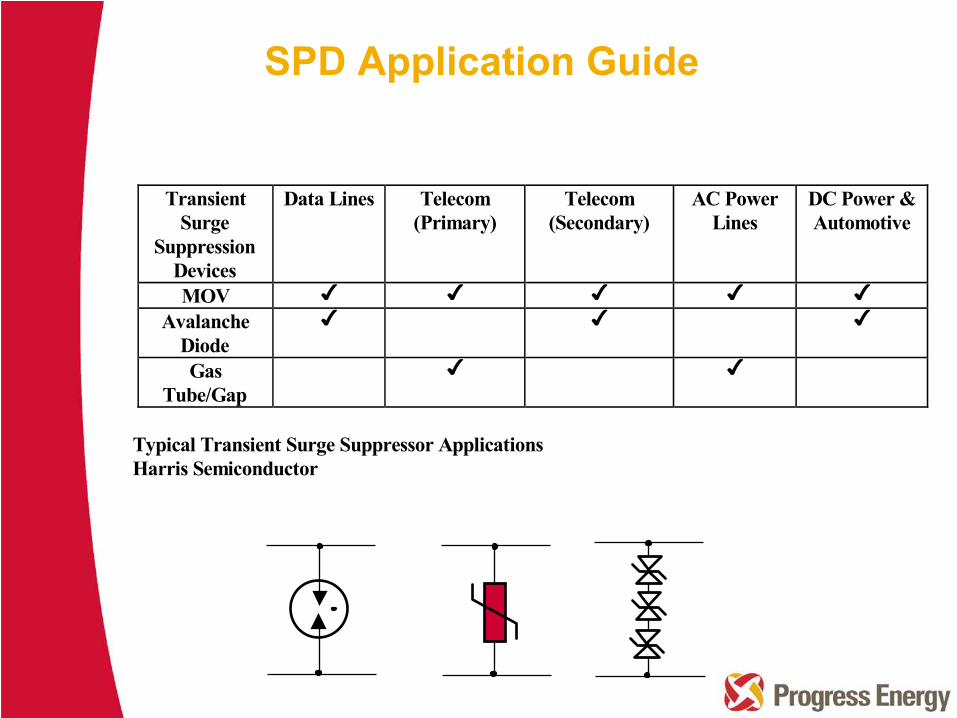
SPD Application Guide
TransientSurge
SuppressionDevices
Data Lines Telecom(Primary)
Telecom(Secondary)
AC PowerLines
DC Power &Automotive
MOVAvalanche
DiodeGas
Tube/Gap
Typical Transient Surge Suppressor Applications Harris Semiconductor
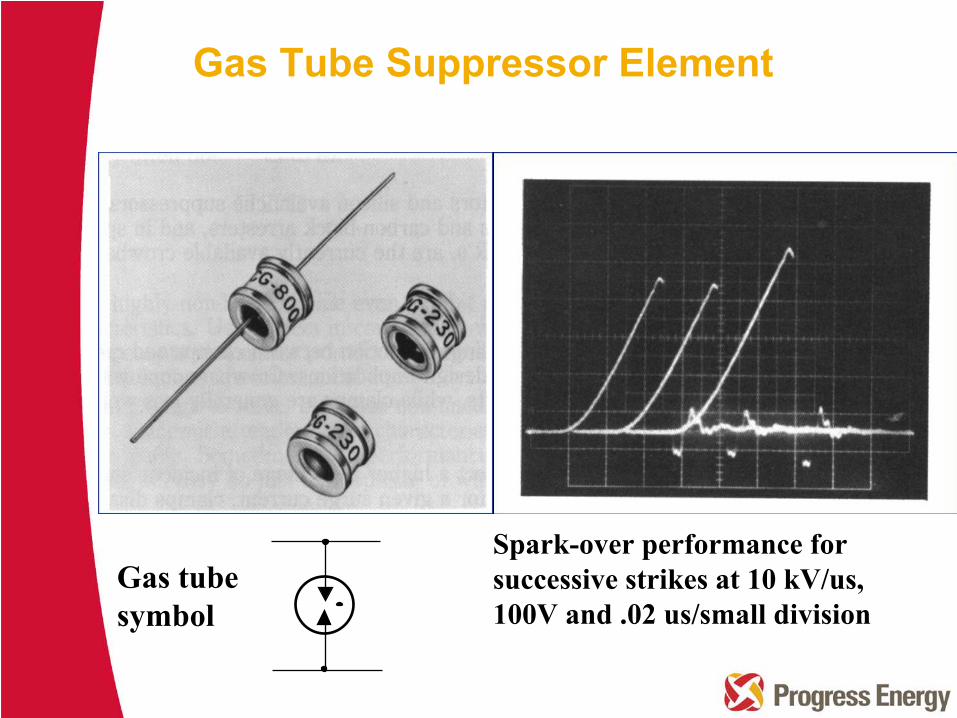
Gas tube symbol
Spark-over performance for successive strikes at 10 kV/us, 100V and .02 us/small division
Gas Tube Suppressor Element
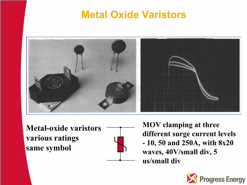
Metal-oxide varistorsvarious ratingssame symbol
MOV clamping at threedifferent surge current levels -
10, 50 and 250A, with 8x20
waves, 40V/small div, 5 us/small div
Metal Oxide Varistors
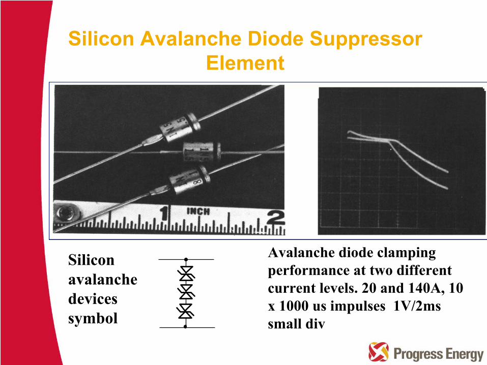
Silicon avalanchedevices symbol
Avalanche diode clamping performance at two different current levels. 20 and 140A, 10 x 1000 us impulses 1V/2ms small div
Silicon Avalanche Diode Suppressor Element
Interpretation for IEEE Std 1050- 1996
The caution that "the use of one or more isolated ground rods
as the
signal reference ground is a safety hazard and is not recommended"
is not explicitly explained in IEEE Std 1050-1996 since it is well
covered in the IEEE Green Book © (IEEE Std 142-1991) and the
IEEE Emerald Book © (IEEE Std 1100-1996).
The most basic safety hazard is that the isolated ground reference
does not have a direct connection back to the system source which
could prevent protective devices from operating because of the high
impedance that is introduced. Equipment damage from transients
such as lightning is also a real concern.
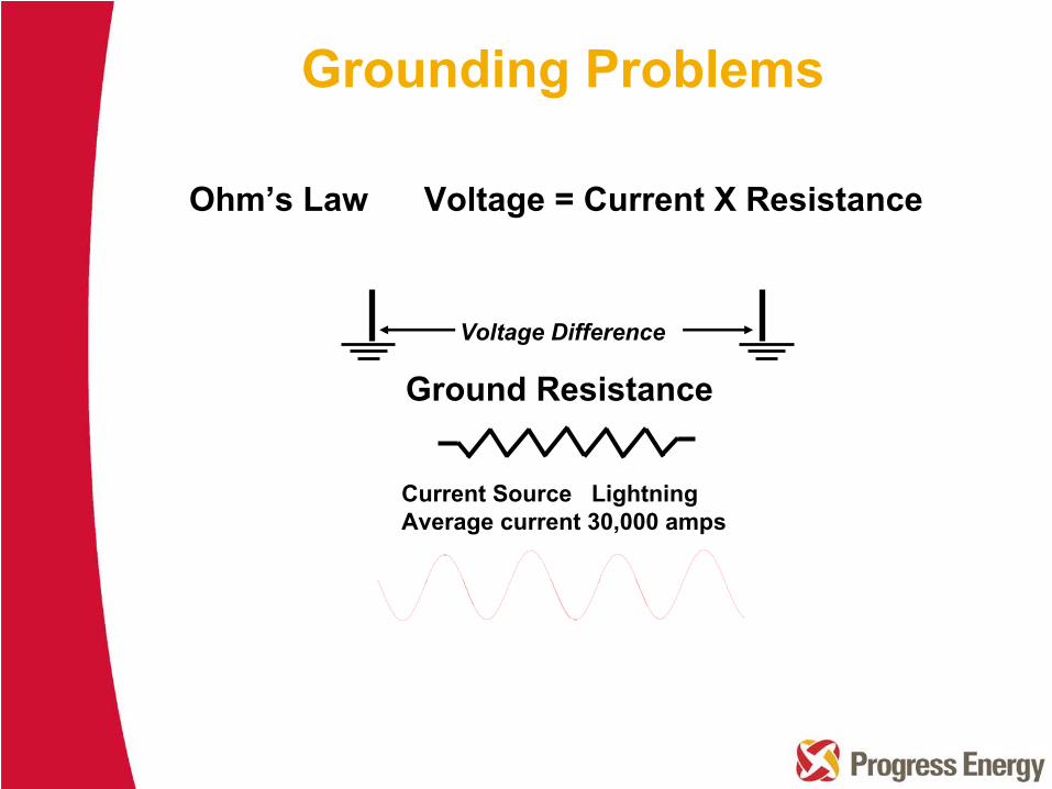
Grounding Problems
Current Source Lightning Average current 30,000 amps
Voltage Difference
Ground Resistance
Ohm’s Law Voltage = Current X Resistance
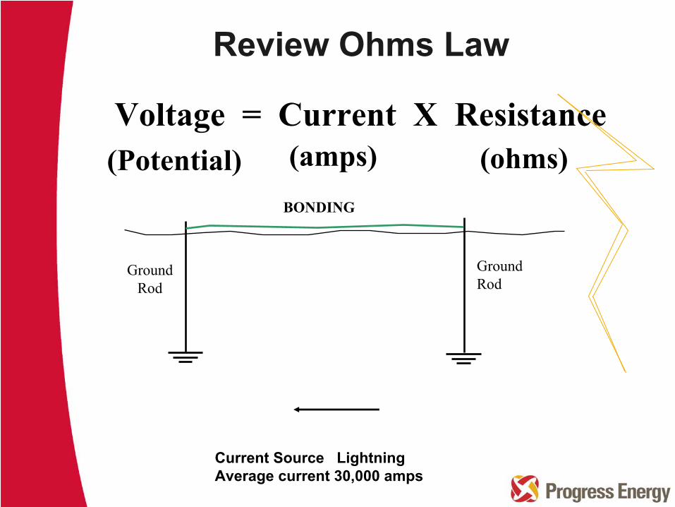
Review Ohms Law
Voltage = Current X Resistance(ohms)(Potential) (amps)
Develop VOLTAGEDevelop VOLTAGE
BONDING
GroundRod
GroundRod
Current Source Lightning Average current 30,000 amps
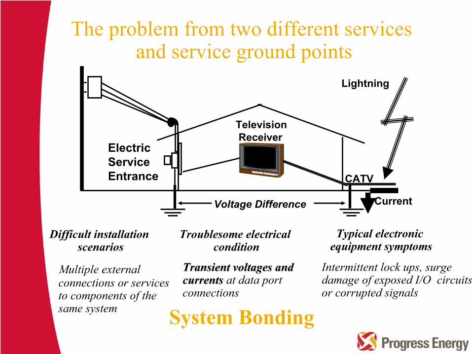
CATV
Electric ServiceEntrance
Television Receiver
Lightning
Voltage Difference Current
Difficult installationscenarios
Troublesome electricalcondition
Typical electronic equipment symptoms
Multiple external connections or services to components of the same system
Transient voltages and Transient voltages and currentscurrents
at data port connections
Intermittent lock ups, surge damage of exposed I/O circuits or corrupted signals
The problem from two different services and service ground points
System Bonding

Bonding and Grounding
Phone SystemCable SystemLAN SystemControl and Communication
TransducersSensors
Internal Interface
Communications
Fiber OpticOptical CouplingLast resort to float one end of the grounding this is usually not as successful.Radio communicationOne power source for all systems.
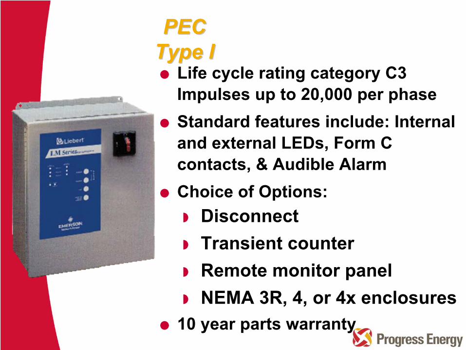
Life cycle rating category C3 Impulses up to 20,000 per phaseStandard features include: Internal and external LEDs, Form C contacts, & Audible AlarmChoice of Options:
DisconnectTransient counterRemote monitor panelNEMA 3R, 4, or 4x enclosures
10 year parts warranty
PEC PEC Type IType I
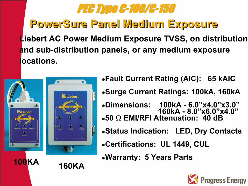
Liebert
AC Power Medium Exposure TVSS, on distribution and sub-distribution panels, or any medium exposure locations.
Fault Current Rating (AIC): 65 kAICSurge Current Ratings: 100kA, 160kADimensions: 100kA - 6.0”x4.0”x3.0”
160kA - 8.0”x6.0”x4.0”50 Ω EMI/RFI Attenuation: 40 dBStatus Indication: LED, Dry ContactsCertifications: UL 1449, CULWarranty: 5 Years Parts100KA 160KA
PowerSure
Panel Medium ExposurePowerSure
Panel Medium ExposurePEC Type CPEC Type C--100/C100/C--150150
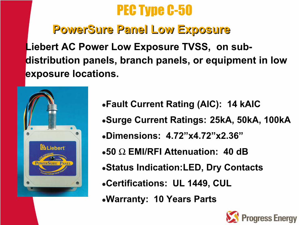
Fault Current Rating (AIC): 14 kAICSurge Current Ratings: 25kA, 50kA, 100kADimensions: 4.72”x4.72”x2.36”
50 Ω EMI/RFI Attenuation: 40 dBStatus Indication:LED, Dry ContactsCertifications: UL 1449, CULWarranty: 10 Years Parts
Liebert
AC Power Low Exposure TVSS, on sub- distribution panels, branch panels, or equipment in low
exposure locations.
PowerSure
Panel Low ExposurePowerSure
Panel Low ExposurePEC Type C-50

UL 1449 Suppressed Voltage Rating (Standard Voltage Rating)
L-N
L-G
L-L N-G
120/208
400
400
700 400
277/480
800
800
1500
800
240
700
800
480
1500
1500
Single Point Grounding of SystemsVisual check grounding system and system bonding point Conduct risk evaluation (identify vulnerable appliances, equipment, and telephone and computer systems)Surge protection of external servicesAdditional internal SPD at equipmentConductor length short to SPD
Recommended practices