TVA’s Grid Resiliency Direction - IEEE Standards …€™s Grid Resiliency Direction ... New...
51
TVA’s Grid Resiliency Direction Clayton Clem, Tennessee Valley Authority VP Transmission Engineering
Transcript of TVA’s Grid Resiliency Direction - IEEE Standards …€™s Grid Resiliency Direction ... New...
TVA’s Grid Resiliency Direction
Clayton Clem, Tennessee Valley Authority
VP Transmission Engineering

Tennessee Valley Authority
2
A federally-owned, self-financed corporation
Created in 1933 by the TVA Act
Mission: Provide navigation, flood control, & electric power in the Tennessee Valley region
Largest public power system
Service Area:
¾ Parts of 7 states
¾ 80,000 square miles
¾ 9 million people
Primarily a wholesaler of power serving distributors
TVA also sells power to direct served customers.

TVA’s Mission of Service
3
Aligning TVA’s Transmission Grid with the mission by providing the connectivity, flexibility and resiliency to serve the people of the Valley.
Energy Economic DevelopmentEnvironment

What We Manage
4
¾ 16,194 miles of lines
¾ 512 substations/switchyards
¾ 104,467 transmission structures on 237,528 right-of-way acres
¾ 1,293 individual interconnection & customer connection points
¾ 2,700-mile fiber network
¾ 33,500 MW peak load

Transmission Grid Resiliency
Resiliency- the capacity to adapt, withstand & recover quickly from disruptions; toughness
Resiliency is not new. It is and has been an essential element of being responsible custodians of the public trust as grid owners and operators.
¾ Traditional Key Elements have always involved:
¾ Design standards
¾ Operating procedures
¾ Emergency planning
¾ Emergency inventory
¾ Restoration Activities Critical
5

Transmission Grid Resiliency
6
Our industry has changed
¾ Public expectations have changed.
¾ Excess transmission capacity is largely gone.
¾ We don’t have the same workforce.
¾ Challenges to resiliency today are much broader.
As Hurricane Sandy and the Fukushima tsunami showed, natural or human events can cause much more severe damage in a densely developed infrastructure. Even if unlikely, these risks must be considered.
16 Critical Infrastructure Sectors: all depend on electricity.

Transmission Grid Resiliency
7
Hurricane KatrinaAugust 29, 2005

Transmission Grid Resiliency
8
Hurricane Sandy – October 2012
¾ Grid Resiliency became part of the national transmission dialog after Super Storm Sandy (hurricane impacting the northeast in 2012).
¾ New York Public Service Commission (PSC) has drafted an Emergency Response Performance Measures scorecard.
¾ Changes in Public Service Law (PSL) provide the PSC with authority to assess civil penalties against utilities.
¾ NY Draft Scorecard Components: Preparations (10%), Operational Response (60%), Communication (30%)
¾ Super storms and their impact have changed the reliability discussion forever. Traditional reliability measures do not cover events like these.
¾ Customer and political pressures are driving changes in emergency response expectations.
New Expectations- 90% damage assessment within 24 hours- 100% of crews available pre-event- Desire to have full recovery within 3 days
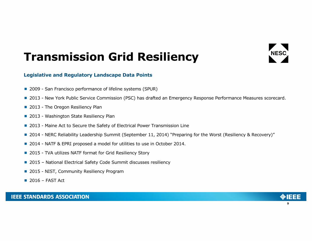
Transmission Grid ResiliencyLegislative and Regulatory Landscape Data Points
¾ 2009 - San Francisco performance of lifeline systems (SPUR)
¾ 2013 - New York Public Service Commission (PSC) has drafted an Emergency Response Performance Measures scorecard.
¾ 2013 - The Oregon Resiliency Plan
¾ 2013 - Washington State Resiliency Plan
¾ 2013 - Maine Act to Secure the Safety of Electrical Power Transmission Line
¾ 2014 - NERC Reliability Leadership Summit (September 11, 2014) “Preparing for the Worst (Resiliency & Recovery)”
¾ 2014 - NATF & EPRI proposed a model for utilities to use in October 2014.
¾ 2015 - TVA utilizes NATF format for Grid Resiliency Story
¾ 2015 – National Electrical Safety Code Summit discusses resiliency
¾ 2015 - NIST, Community Resiliency Program
¾ 2016 – FAST Act
9

Transmission Grid Resiliency
10
Connectivity: Everyone wants a grid with the connectivity to move power around & minimize environmental impacts.
Flexibility: That adapts to the changing picture of where generation can come from and maintains grid reliability.
Resiliency: To withstand extreme climatic events, major equipment failures, physical attacks, cyber-attacks, solar storms, etc.
To serve the needs of the public today
Our idea of resiliency and what the resiliency scope entails has expanded and continues to evolve.

Hazards / Threats
GMD EMP Physical Attack
Cyber Attack
Severe Weather
Reduced Workforce
Single Point
FailureOther?
Assess
Prevent / Harden
Detect / Monitor
Recover / Restore
North American Transmission Forum (NATF) / Electric Power Research Institute (EPRI) Format
11
Superior Practices / Research Topics

TVA’s Expanded Adaptation
12
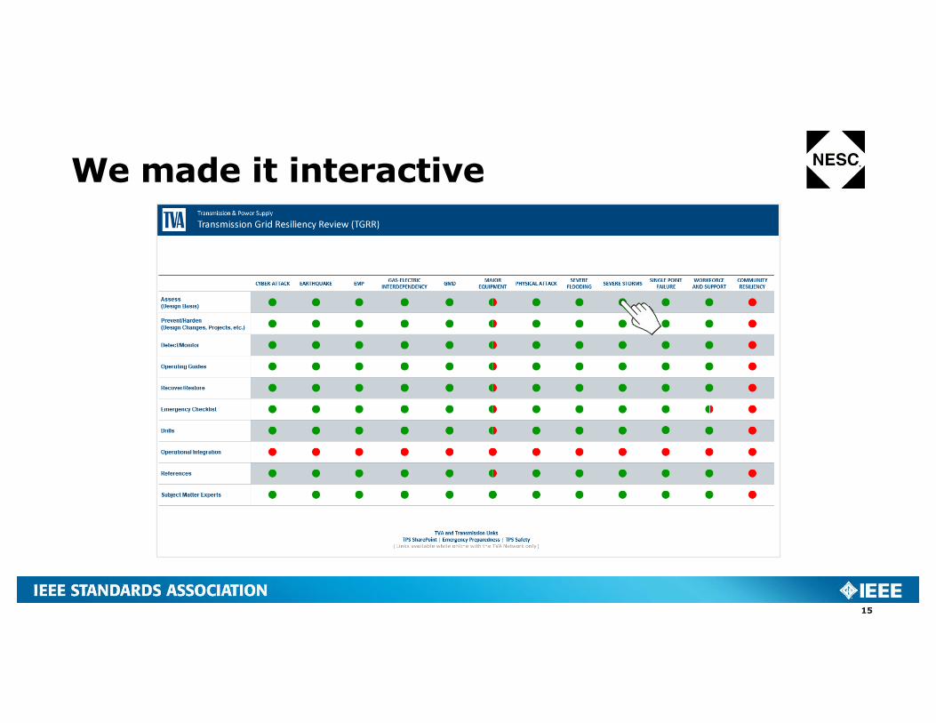
¾ We liked the NATF/EPRI model and TVA added to it by incorporating operating guides, emergency checklists, drills, references and subject matter experts.
¾ Wider range of risks – added earthquake, gas electric interdependency, major equipment, severe flooding, severe storms and workforce support.
¾ We made it interactive and linked reference material.
¾ We recognized the knowledge transfer value.

We made it interactive
13

We made it interactive
14
We made it interactive
15

We made it interactive
16

Yellow = out of serviceGreen = Returned to service
January 27, 2009 Kentucky Ice Storm System outage map at de-activation

TVA’s Expanded Adaptation
18
¾ Cyber Attack
¾ Earthquake
¾ EMP
¾ Gas-Electric Interdependency
¾ GMD
¾ Major Equipment
¾ Physical Attack
¾ Severe Flooding
¾ Severe Storms
¾ Single Point Failure
¾ Workforce and Support
¾ Community Resiliency
The risks cover a range from high to low probability.
Probability of man made events is unpredictable.
TVA resiliency planning is transitioning to a much wider view of potential severe risks.

Cyber Attack
19
Problem:
Potentially system-wide, unexpected loss of communication and control, possibility of equipment damage
Response:
¾ Defense in depth
¾ Procedures – CIP, NIST/FISMA
¾ Continuous internal monitoring 24/7
¾ External monitoring
¾ Recovery plan
¾ Drills
¾ Equipment reviews
¾ Audits, reassessment & revised protocols
¾ Partner with federal, state and local law enforcement & key industry security groups such as E-ISAC.
Reported attacks are escalating – energy sector is an obvious and strategic target

Cyber Attack – Growing & Evolving Threats
20
Some recent attacks in the news
¾ Sophisticated Cyber-Attack May Have Targeted the Joint Chiefs of Staff
¾ Cyber Attack at the White House
¾ Bank Regulators Warn of 'Armageddon' Cyber Attack
¾ Anthem Health Insurance Confirms Cyber Attack
¾ White House Takes Action After North Korea Cyber-Attack
¾ How Should U.S. Respond to Sony Cyber Attack?
¾ Office of Personnel Management (OPM) data breach is among the largest breaches of government data.
¾ Ukraine power outage, December 2015

Earthquake – New Madrid Seismic Zone
21
Problem:
Potentially widespread, unexpected, coincident damage (water, transport, injuries), involves equipment with long replacement times.
¾USGS estimates 1811-1812 event has a 7-10% probability in 50 years
¾M6 has a 25-40% probability in 50 years.
Response:
¾ Tie-down large power transformers
¾Structurally harden masonry switch houses.
¾Replace old equipment with seismically resistant.
¾Revise procurement specifications to require seismically qualified equipment.
¾Shake table tests on a 500-kV transformer bushing to determine resiliency and conductor slack for bus connection.
1811-12M7-8

Earthquake – Hardening the Switch Houses
22

Earthquake – Other Enhancements & Mitigation
23

EMP and IEMI
24
Problem:
Potentially very widespread, unexpected, coincident damage (water, transport, communications, injuries), many unknowns including ability to recognize what equipment is non-functional. Skills availability, crew support, nuclear plant shutdowns, are issues.
Response:
¾ Coordinate with industry evaluations
¾ Coordinate with State emergency actions
¾ Enhance black start and emergency plans with priorities for supply to new normal
¾ Use hydro and limited hardening as nucleus for rebuilding
¾ Restore older skills – manual restarts, ham radio
¾ Hardened Test Equipment & Communications equipment storage

EMP and IEMI
25
Changing Environment
New players with attack capabilities, evolving technology has increased vulnerability
New interest – EIS Council, Sen. Franks (Critical Infrastructure Protection Act), TVC Secure Grid Initiative, State Health Commissioners
EM Pulse E1-E2-E3
E2 and E3 already addressed with GMD and lightning protection
Planning
¾ Impossible to harden entire power grid
¾ Preserve core essentials as basis for system restart (black start generators & lines, communications)
¾ Short term: ensure ability to restart from basic resources
¾ Long term: harden key equipment (diesels, switch houses, relays), research unknowns

Gas-Electric Interdependency
26
Problem:
Gas supplies are vulnerable to source disturbance (Katrina), pipeline damage, alternative demand due to cold weather
¾ Importance to TVA:
¾ Gas generation (CC& CT) 9.95 GW capacity – most with dual fuel
¾ 10% of TVA energy in 2005, 23% in 2025
¾ 10 pipeline companies, 65 pumping stations (16 electric powered)
Response
¾ Use of firm delivery options
¾ Interaction studies – large generating plant loss (alternative fuel makeup), pipeline loss (pipeline redundancy, dual fuel, storage)
¾ Assess individual supply to electric-powered pumping stations, restoration priority

Gas-Electric Interdependency
27
Operational awareness used to prioritize restoration efforts

GMD
28
Problem:
¾ Potentially widespread injection of Geomagnetic Induced Current (near-dc) causing harmonics and overheating of transformers. There will be reasonable notice of impending storms. (new DSCOVR satellite)
Response:
¾ Operating procedures to ensure operator awareness
¾ Replaced vulnerable relays on capacitor banks
¾ Network of 12 Sunburst detectors plus magnetometer
¾ Researched blocking device design
¾ Assessment of 144 500-kV transformers for saturation and heating
¾ GIC system model and studies in anticipation of TPL-007
¾ Stepped operating response vs storm severity
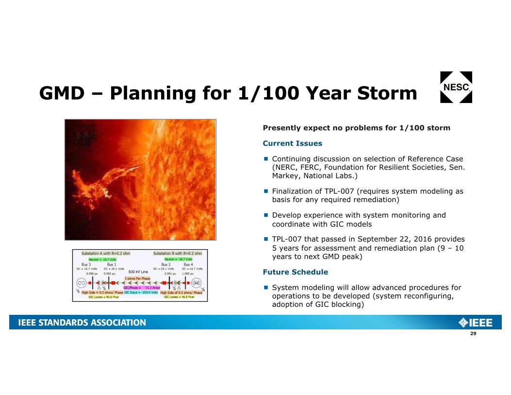
GMD – Planning for 1/100 Year Storm
29
Presently expect no problems for 1/100 storm
Current Issues
¾ Continuing discussion on selection of Reference Case (NERC, FERC, Foundation for Resilient Societies, Sen. Markey, National Labs.)
¾ Finalization of TPL-007 (requires system modeling as basis for any required remediation)
¾ Develop experience with system monitoring and coordinate with GIC models
¾ TPL-007 that passed in September 22, 2016 provides 5 years for assessment and remediation plan (9 – 10 years to next GMD peak)
Future Schedule
¾ System modeling will allow advanced procedures for operations to be developed (system reconfiguring, adoption of GIC blocking)

Major Equipment
30
Problem:
Large equipment is vulnerable to physical and electrical disturbances, difficult to relocate, requires a long time to repair and replace.
Response:¾ Appropriate seismic requirements specified for
major equipment per IEEE 693 (ex. power transformers, circuit breakers, instrument transformers)
¾ Wind loading requirements and regional ice loading requirements for specific major equipment and interconnected bus work and insulators.
¾ Provide slack in jumper connections to transformer bushings for seismic movements

Major Equipment
31
Problem:
Large equipment is vulnerable to physical and electrical disturbances, difficult to relocate, requires a long time to repair and replace.
Response:
¾Utilization of composite bushings for circuit breakers and housings for some instrument transformers
¾Foundations based on soil types and consistencies.
¾Equipment standardization and multiple suppliers for assurance of supply
CompositeShed Damage
Major Equipment
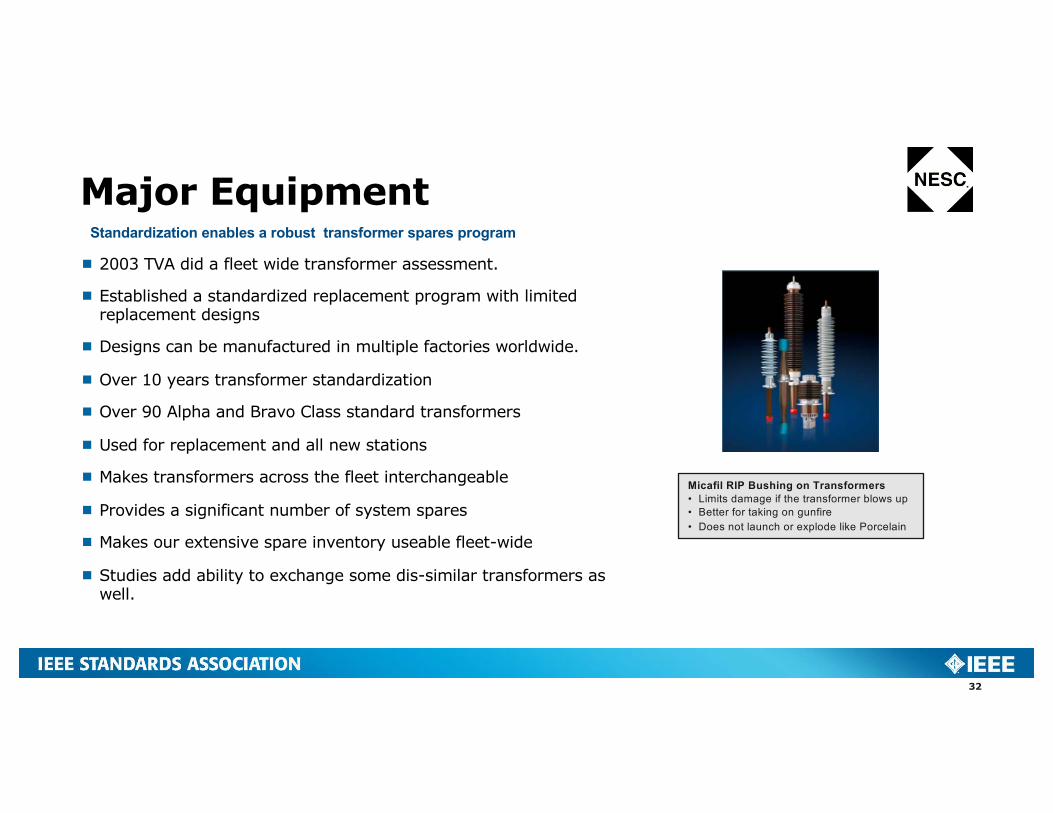
¾ 2003 TVA did a fleet wide transformer assessment.
¾ Established a standardized replacement program with limited replacement designs
¾ Designs can be manufactured in multiple factories worldwide.
¾ Over 10 years transformer standardization
¾ Over 90 Alpha and Bravo Class standard transformers
¾ Used for replacement and all new stations
¾ Makes transformers across the fleet interchangeable
¾ Provides a significant number of system spares
¾ Makes our extensive spare inventory useable fleet-wide
¾ Studies add ability to exchange some dis-similar transformers as well.
32
Micafil RIP Bushing on Transformers• Limits damage if the transformer blows up• Better for taking on gunfire • Does not launch or explode like Porcelain
Standardization enables a robust transformer spares program

Major Equipment
33
Standardization enables fast restoration after loss of 500-kV or 161-kV station.
¾ Simplifies Restoration Emergency Inventory– 500-kV Vertical Reach Switches– 500-kV Voltage Transformers (VT)– Coupling capacitor VT (CCVT)– Wavetraps– 161-kV Power VT (PVT) for station service– 4000 A, 0.22 ohm Reactors
¾ Temporary control houses in shipping containers
¾ Mobile transformers and mobile GIS switch gear
Physical Attack
34
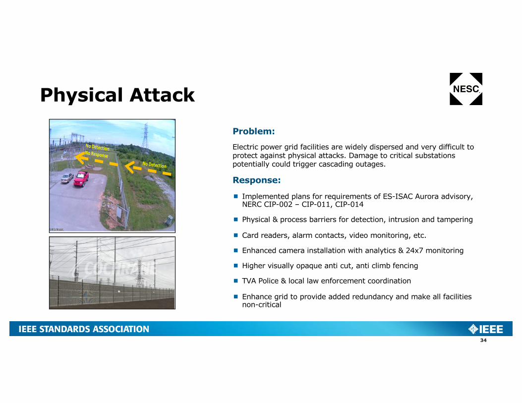
Problem:
Electric power grid facilities are widely dispersed and very difficult to protect against physical attacks. Damage to critical substations potentially could trigger cascading outages.
Response:
¾ Implemented plans for requirements of ES-ISAC Aurora advisory, NERC CIP-002 – CIP-011, CIP-014
¾ Physical & process barriers for detection, intrusion and tampering
¾ Card readers, alarm contacts, video monitoring, etc.
¾ Enhanced camera installation with analytics & 24x7 monitoring
¾ Higher visually opaque anti cut, anti climb fencing
¾ TVA Police & local law enforcement coordination
¾ Enhance grid to provide added redundancy and make all facilities non-critical

Physical Attack
CIP-014-2:
¾ Automation tools used to evaluate multiple methodologies to determine cascading scenarios.
¾ Each methodology simulated the total loss of a substation as a result of a physical attack in steady-state and dynamic analyses.– Three-phase faults at all voltage levels at a
substation isolated remotely with normal clearing– Single-phase faults at all voltage levels at a
substation isolated remotely with delayed clearing
¾ Instability & cascading criteria determined by internal analysis and industry benchmarking which align with NATF survey results.
¾ System upgrades can be implemented to remove sites from the critical list.

Flooding
36
Problem:
¾ Extreme weather can cause flooding and threaten grid equipment. Example: 15 inches of rain in 2 days of May 2010 caused a river crest 25.5 feet above flood stage.
Response:
¾ Transmission assets reviewed using FEMA flood data as layers in TVA GIS map
¾ Multiple Flood Hazard scenarios were considered including – 1% annual chance (100 year flood)– Regulatory floodway– Special floodway – 0.2% annual chance (500 year flood)– Future conditions 1% annual chance– TVA’s Zone A Probable Maximum Flood for the Tennessee River
¾ Relocate assets to areas that will not flood. In the example above, a 161-kV substation was relocated

Flooding – Nashville 2010
37

Flooding – TVA Substations Located Within FEMA Flood Zones
38

Storms
39
Problem:
¾ Extreme weather including tornadoes and ice storms can cause mechanical loads on substations and transmission structures to exceed design limits.
Response:
¾ Maintain and mobilize crews in advance, anticipate communication and support requirements (food, lodging) during restoration.
¾ Replace wood poles with steel for new construction and preventive maintenance, use robust alumoweld shield wire. Apply icing criteria to minimize faults when re-energizing.
¾ Developed steel inventory plan for restoration utilizing a limited number of standard TVA tower types to reduce inventory.
¾ Collaboration with the U.S. Army Cold Regions Research and Engineering Laboratory to create the Region 2 Ice Maps as basis for NESC 250D - Extreme Ice.

TVA Ice Storm Historical Data
40
1934
1951
1960
1974

February 8-12, 1994 Ice Storm
41
Strategic Steel Inventory
42
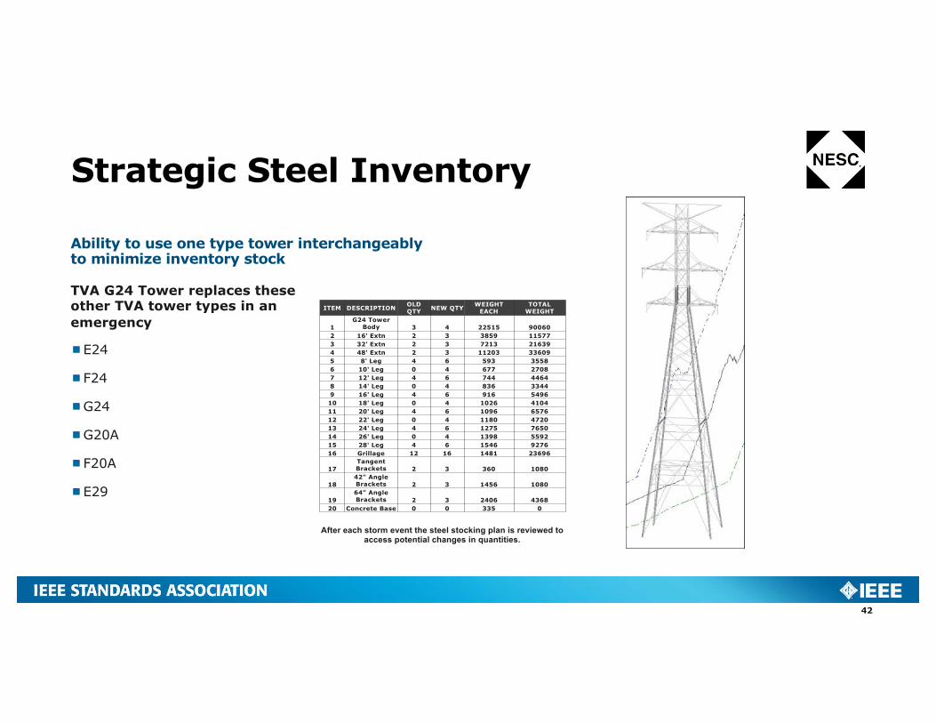
TVA G24 Tower replaces these other TVA tower types in an emergency
¾E24
¾F24
¾G24
¾G20A
¾F20A
¾E29
Ability to use one type tower interchangeably to minimize inventory stock
ITEM DESCRIPTION OLD QTY NEW QTY WEIGHT
EACHTOTAL
WEIGHT
1G24 Tower
Body 3 4 22515 900602 16' Extn 2 3 3859 115773 32' Extn 2 3 7213 216394 48' Extn 2 3 11203 336095 8' Leg 4 6 593 35586 10' Leg 0 4 677 27087 12' Leg 4 6 744 44648 14' Leg 0 4 836 33449 16' Leg 4 6 916 5496
10 18' Leg 0 4 1026 410411 20' Leg 4 6 1096 657612 22' Leg 0 4 1180 472013 24' Leg 4 6 1275 765014 26' Leg 0 4 1398 559215 28' Leg 4 6 1546 927616 Grillage 12 16 1481 23696
17Tangent Brackets 2 3 360 1080
1842" Angle Brackets 2 3 1456 1080
1964" Angle Brackets 2 3 2406 4368
20 Concrete Base 0 0 335 0
After each storm event the steel stocking plan is reviewed to access potential changes in quantities.
Transmission Restoration Material
43
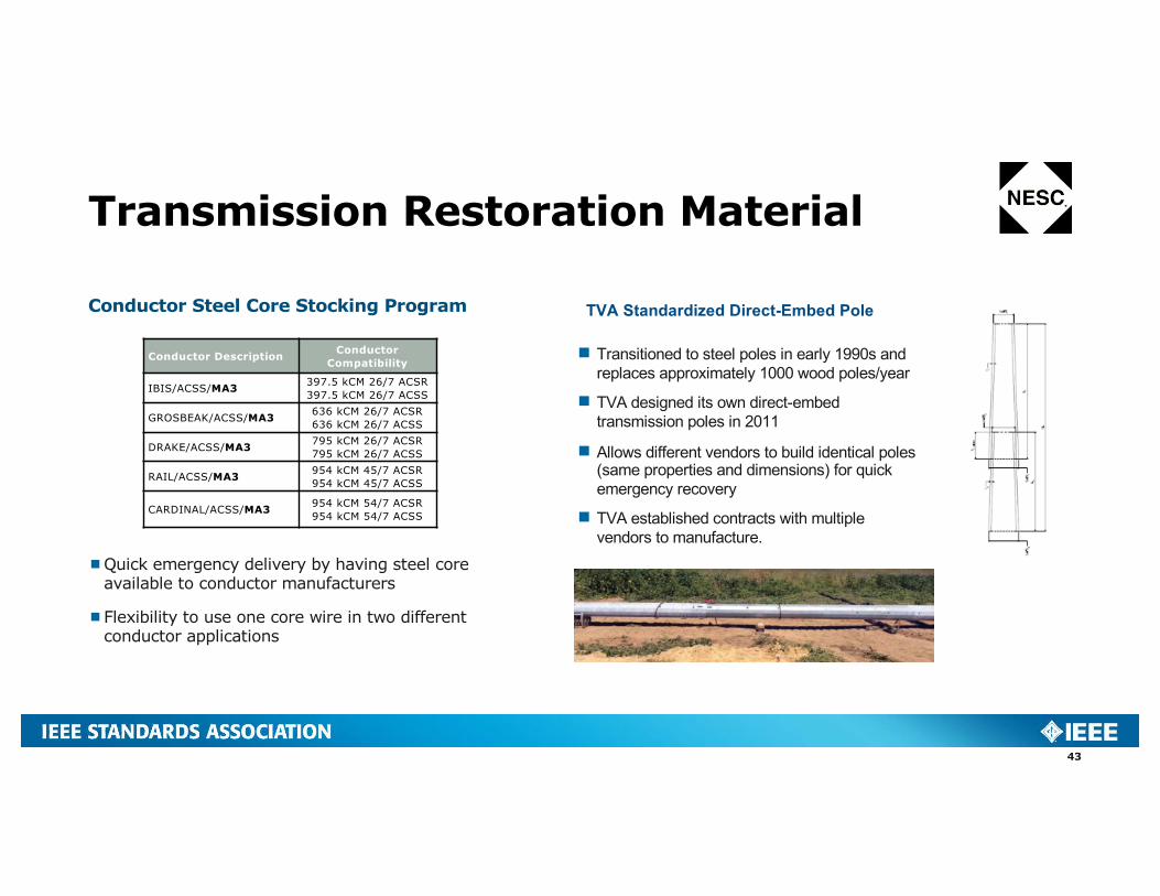
¾Quick emergency delivery by having steel core available to conductor manufacturers
¾Flexibility to use one core wire in two different conductor applications
Conductor Steel Core Stocking Program
Conductor Description Conductor Compatibility
IBIS/ACSS/MA3 397.5 kCM 26/7 ACSR 397.5 kCM 26/7 ACSS
GROSBEAK/ACSS/MA3 636 kCM 26/7 ACSR 636 kCM 26/7 ACSS
DRAKE/ACSS/MA3 795 kCM 26/7 ACSR 795 kCM 26/7 ACSS
RAIL/ACSS/MA3 954 kCM 45/7 ACSR 954 kCM 45/7 ACSS
CARDINAL/ACSS/MA3 954 kCM 54/7 ACSR 954 kCM 54/7 ACSS
TVA Standardized Direct-Embed Pole
¾ Transitioned to steel poles in early 1990s and replaces approximately 1000 wood poles/year
¾ TVA designed its own direct-embed transmission poles in 2011
¾ Allows different vendors to build identical poles (same properties and dimensions) for quick emergency recovery
¾ TVA established contracts with multiple vendors to manufacture.

Single Point Failure
44
Problem:
Protection System single point of failure that causes an adverse impact to the BES
Elements to consider include:
¾ DC Control Circuitry
¾ Station DC Supply
¾ Protective Relays (including auxiliary relays)
¾ Communication Systems
¾ AC Current & Voltage Inputs
Response:
¾ 2007 – IEEE PSRC developed white paper on Redundancy Considerations for Protective Relay Systems
¾ 2009 – NERC System Protection and Controls Subcommittee released a white paper on Protection System reliability
¾ 2012 – FERC Order 754 data request required the industry to provide statics for single point of failure vulnerability for Protection Systems.
¾ 2016 – TPL-001-4 clarified evaluation and mitigation for Protection System failure events.

Single Point Failure
45
TVA Actions¾TVA has revised design standards to address redundancy inadequacy for…
o Protection Systemso Non-redundant AC & voltage inputso Non-redundant DC control circuitryo Two independent DC supplies
¾TPL-001-4 evaluation determined the impact of Protection System failureso Mitigation required for P5 events impacting facility's assuming a single line to ground faulto Extreme events, 3-phase faults, require evaluation but not mitigationo TVA screening study process uses principles consistent with FERC Order 754o Final evaluation resulted in projects to enhance redundancy
¾TVA has made a significant effort in recent years to provide redundant Protection Systems on new installations and modifications to existing stations.
Next Steps¾ Walk downs on large generation sites and large customer loads.¾ Considering overall asset condition and establishing any needed corrective actions.
Influenced by FERC Order 754
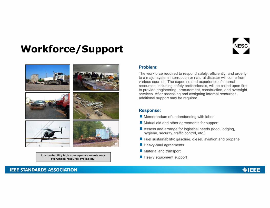
Workforce/SupportProblem:The workforce required to respond safely, efficiently, and orderly to a major system interruption or natural disaster will come from various sources. The expertise and experience of internal resources, including safety professionals, will be called upon first to provide engineering, procurement, construction, and oversight services. After assessing and assigning internal resources, additional support may be required.
Response:¾Memorandum of understanding with labor¾Mutual aid and other agreements for support¾Assess and arrange for logistical needs (food, lodging,
hygiene, security, traffic control, etc.)¾ Fuel sustainability: gasoline, diesel, aviation and propane¾Heavy-haul agreements¾Material and transport¾Heavy equipment supportLow probability high consequence events may
overwhelm resource availability.

§ Chemical§ Commercial facilities§ Communications§ Critical manufacturing§ Dams§ Defense industrial base§ Emergency services§ Energy§ Financial services§ Food & agriculture§ Government facilities§ Healthcare & public health§ Information technology§ Nuclear reactors, materials & waste§ Transportation systems§ Water & wastewater systems
Community Resiliency16 Critical Infrastructure Sectors – all depend on electricity.
(McAllister 2013)
Size & scope
of disaster &
recovery
efforts
National Disaster Recovery Framework recovery continuum (FEMA 2011)
Enhancing community resiliency requires coordination of multiple preparedness and emergency plans
Response:§ Integrate resiliency planning with LPCs and communities§ Mutual aid and other agreements for response to unusual disruptions –
communications, operations, engineering§ Strengthen TVA, LPC, and community body alignment using drill-based
scenarios
Problem:In the rare event of prolonged loss of supply, assigning priorities to supply restoration in an LPC system is complex and potentially difficult. TVA knowledge of LPC ability to respond to guidance of facilities management for extreme events or extended restoration times requires substantial preparation and resources.
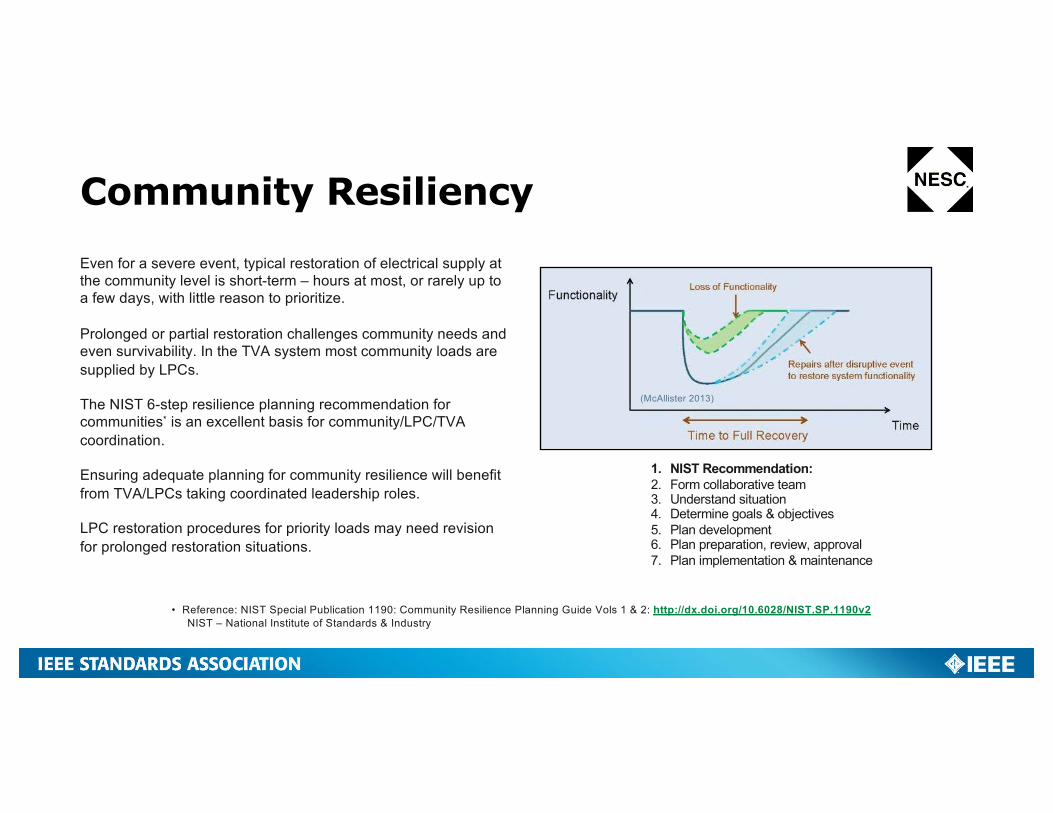
Community ResiliencyEven for a severe event, typical restoration of electrical supply at the community level is short-term – hours at most, or rarely up to a few days, with little reason to prioritize.
Prolonged or partial restoration challenges community needs and even survivability. In the TVA system most community loads are supplied by LPCs.
The NIST 6-step resilience planning recommendation for communities* is an excellent basis for community/LPC/TVA coordination.
Ensuring adequate planning for community resilience will benefit from TVA/LPCs taking coordinated leadership roles.
LPC restoration procedures for priority loads may need revision for prolonged restoration situations.
• Reference: NIST Special Publication 1190: Community Resilience Planning Guide Vols 1 & 2: http://dx.doi.org/10.6028/NIST.SP.1190v2NIST – National Institute of Standards & Industry
(McAllister 2013)
1. NIST Recommendation:2. Form collaborative team3. Understand situation4. Determine goals & objectives5. Plan development6. Plan preparation, review, approval7. Plan implementation & maintenance

Next Steps
¾ Continue enhancing TVA & State Emergency Services collaboration
¾ Working closer with local communities to support community resiliency planning
¾ Update Enterprise & Transmission Emergency Plans
¾ Incorporating National Incident Command System
¾ Grid resiliency activities are being factored into our Regional Strategy Plans connectivity, flexibility & capacity in the grid.
TVA is doing extensive grid planning to assure that we are providing the connectivity and flexibility to meet our mission and serve the 9 million residents of the Tennessee valley.
Resiliency considerations are being factored into our Regional Grid Planning Studies.
49

Questions?
50