TV TRANSMITTERS AND AMPLIFIERS - itelcast.com · summary of the tv equipments presented in the...
33
TV TRANSMITTERS AND AMPLIFIERS
-
Upload
phungnguyet -
Category
Documents
-
view
213 -
download
0
Transcript of TV TRANSMITTERS AND AMPLIFIERS - itelcast.com · summary of the tv equipments presented in the...

TV TRANSMITTERS AND AMPLIFIERS

SUMMARY OF THE TV EQUIPMENTS PRESENTED IN THE SITES
NAME OF THE EQUIPMENT COMPOSED OF: DESCRIPTION
VAM TV MODULATOR TIX U5 IF TO CHANNEL CONVERTER
TTU 1000 LD TAU 1000 LD
LD SERIES MEDIUM/HIGH POWER AMPLIFIER (1000 W) - UHF IV° AND V° BAND
VAM TV MODULATOR TIX U5 IF TO CHANNEL CONVERTER COMBINING UNIT TTU 2000 LD
2 units of TAU 1000 LD LD SERIES MEDIUM/HIGH POWER AMPLIFIER (1000 W) - UHF IV° AND V° BAND
VAM TV MODULATOR TIX U5 IF TO CHANNEL CONVERTER
TAU 25 LD SERIES LOW POWER AMPLIFIER (25 W) - UHF IV° AND V° BAND
COMBINING UNIT TTU 5000 LD
4 units of TAU 1500 LD LD SERIES MEDIUM/HIGH POWER AMPLIFIER (1500 W) - UHF IV° AND V° BAND

TTU 5000 LD AMPLIFIER

TTU 5000 LD FRONT VIEW

TTU 5000 LD AMPLIFIER SECTION BLOCK SCHEMATIC
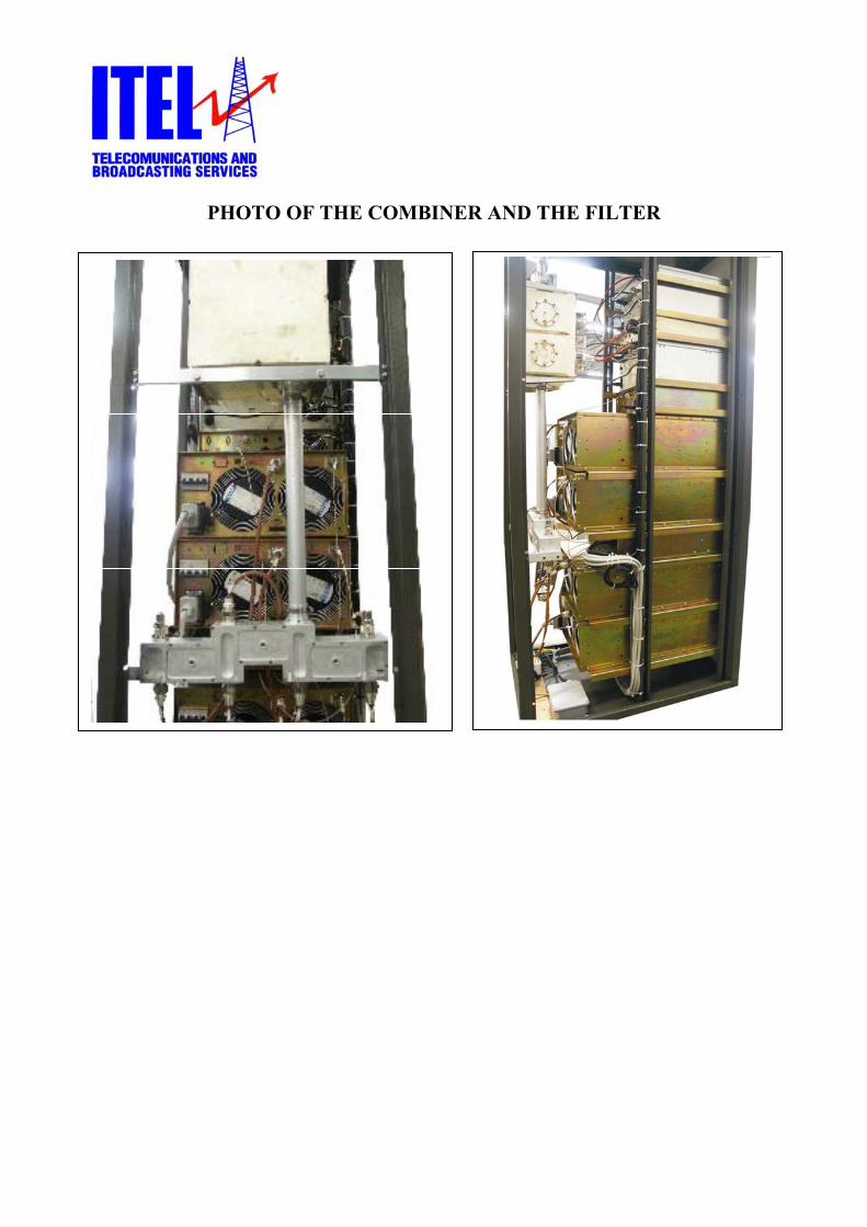
PHOTO OF THE COMBINER AND THE FILTER

VAM MODULATOR
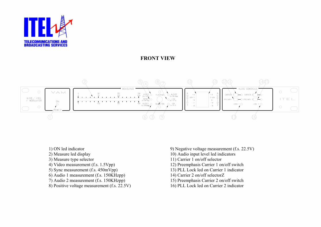
FRONT VIEW
1) ON led indicator 9) Negative voltage measurement (f.s. 22.5V) 2) Measure led display 10) Audio input level led indicators 3) Measure type selector 11) Carrier 1 on/off selector 4) Video measurement (f.s. 1.5Vpp) 12) Preemphasis Carrier 1 on/off switch 5) Sync measurement (f.s. 450mVpp) 13) PLL Lock led on Carrier 1 indicator 6) Audio 1 measurement (f.s. 150KHzpp) 14) Carrier 2 on/off selectorZ 7) Audio 2 measurement (f.s. 150KHzpp) 15) Preemphasis Carrier 2 on/off switch 8) Positive voltage measurement (f.s. 22.5V) 16) PLL Lock led on Carrier 2 indicator
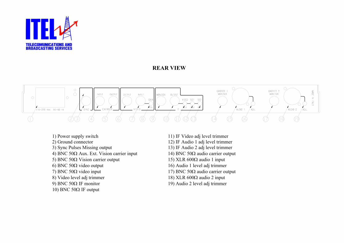
REAR VIEW
1) Power supply switch 11) IF Video adj level trimmer 2) Ground connector 12) IF Audio 1 adj level trimmer 3) Sync Pulses Missing output 13) IF Audio 2 adj level trimmer 4) BNC 50Ω Aux. Ext. Vision carrier input 14) BNC 50Ω audio carrier output 5) BNC 50Ω Vision carrier output 15) XLR 600Ω audio 1 input 6) BNC 50Ω video output 16) Audio 1 level adj trimmer 7) BNC 50Ω video input 17) BNC 50Ω audio carrier output 8) Video level adj trimmer 18) XLR 600Ω audio 2 input 9) BNC 50Ω IF monitor 19) Audio 2 level adj trimmer 10) BNC 50Ω IF output
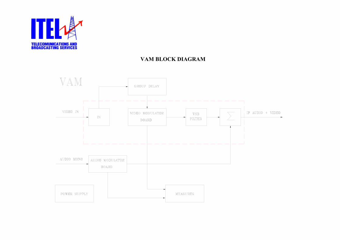
VAM BLOCK DIAGRAM
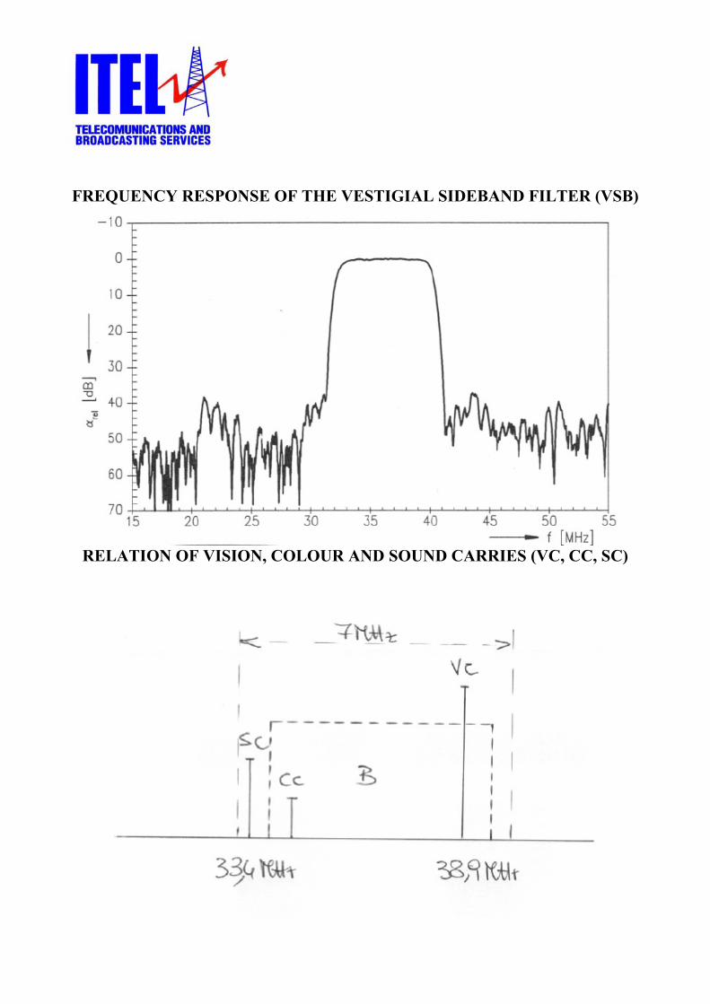
FREQUENCY RESPONSE OF THE VESTIGIAL SIDEBAND FILTER (VSB)
RELATION OF VISION, COLOUR AND SOUND CARRIES (VC, CC, SC)

PHOTO OF THE VAM MODULATOR INTERNAL VIEW

TIX IF CONVERTER
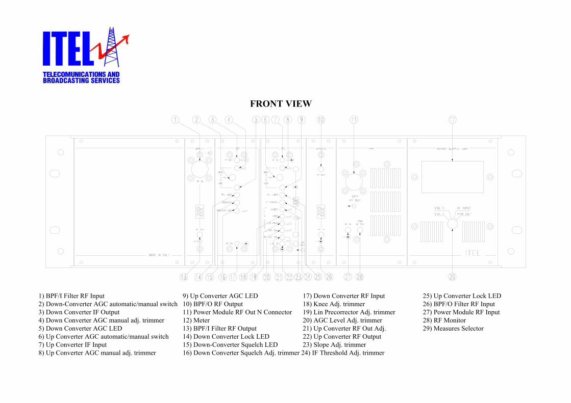
FRONT VIEW
1) BPF/I Filter RF Input 9) Up Converter AGC LED 17) Down Converter RF Input 25) Up Converter Lock LED 2) Down-Converter AGC automatic/manual switch 10) BPF/O RF Output 18) Knee Adj. trimmer 26) BPF/O Filter RF Input 3) Down Converter IF Output 11) Power Module RF Out N Connector 19) Lin Precorrector Adj. trimmer 27) Power Module RF Input 4) Down Converter AGC manual adj. trimmer 12) Meter 20) AGC Level Adj. trimmer 28) RF Monitor 5) Down Converter AGC LED 13) BPF/I Filter RF Output 21) Up Converter RF Out Adj. 29) Measures Selector 6) Up Converter AGC automatic/manual switch 14) Down Converter Lock LED 22) Up Converter RF Output 7) Up Converter IF Input 15) Down-Converter Squelch LED 23) Slope Adj. trimmer 8) Up Converter AGC manual adj. trimmer 16) Down Converter Squelch Adj. trimmer 24) IF Threshold Adj. trimmer

REAR VIEW
1) Mains fuse 2) IF Input SMB Connector 3) ON/OFF Main Switch

IF TO CHANNEL CONVERTER MODULE INTERCONNECTIONS
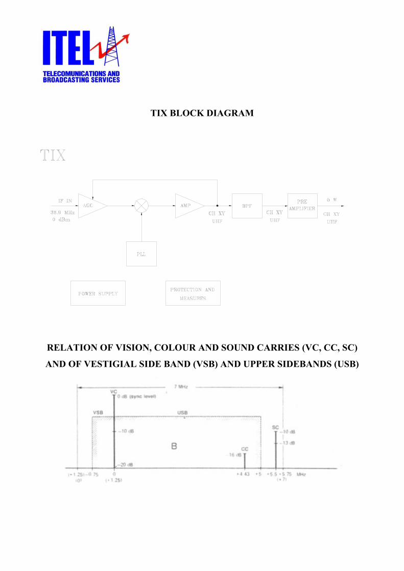
TIX BLOCK DIAGRAM
RELATION OF VISION, COLOUR AND SOUND CARRIES (VC, CC, SC)
AND OF VESTIGIAL SIDE BAND (VSB) AND UPPER SIDEBANDS (USB)

TTU 25 DRIVER

FRONT VIEW
1) RF Monitor BNC connector 6) Shut-down LED indicator 2) RF Input N connector 7) Power ON LED indicator 3) Overheat LED indicator 8) Measure Instrument 4) Overdrive LED indicator 9) Measure Select push button 5) VSWR LED indicator

TAU 1500 LD AMPLIFIER
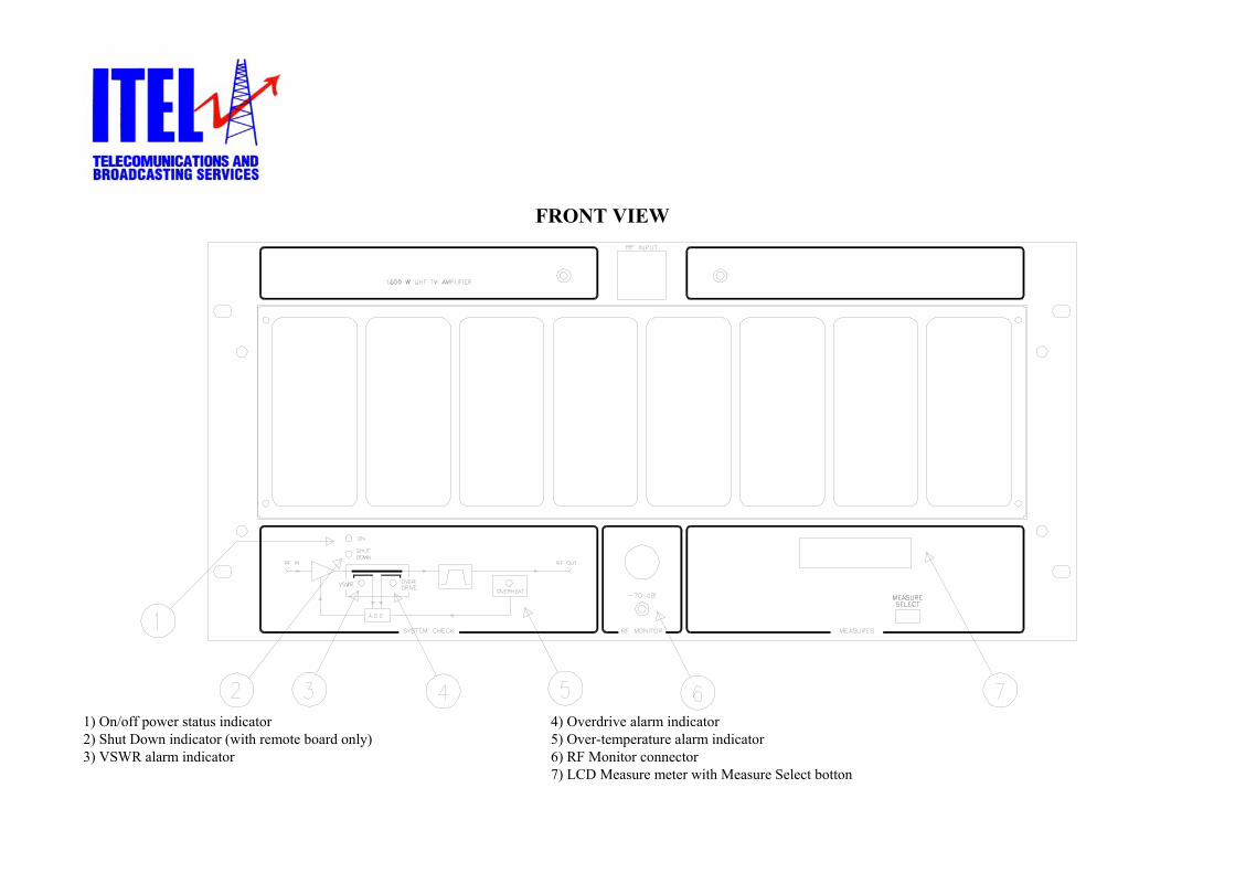
FRONT VIEW
1) On/off power status indicator 4) Overdrive alarm indicator 2) Shut Down indicator (with remote board only) 5) Over-temperature alarm indicator 3) VSWR alarm indicator 6) RF Monitor connector
7) LCD Measure meter with Measure Select botton

REAR VIEW
1) On-Off Authomatic Switch- 4) ENABLE connector 7) RF input N connector 2) Mains AC power supply connector 5) Remote control connector 8) RF output DIN 7/16” connector 3) GND 6) AGC OUT connector 9) AC to Driver connector

RF STAGE
1) LD-MOS amplifier modules 6) Output wilkinson coupler 2) Input wilkinson splitter 7) Input wilkinson splitter 3) Output connection point 8) Input hybrid splitter 4) Output wilkinson coupler 9) LD-MOS amplifier driver module
5) Output hybrid coupler 10) Input power limiter board

POWER SUPPLY STAGE
1) Switching power supply Nr.1 5) Protection board 2) LCD Meter board 6) Directional coupler board 3) Switching power supplys 7) Fuses 4) Remote control optional board

RF STAGE BLOCK DIAGRAM

PHOTO OF THE INTERNAL VIEW (RF STAGE)
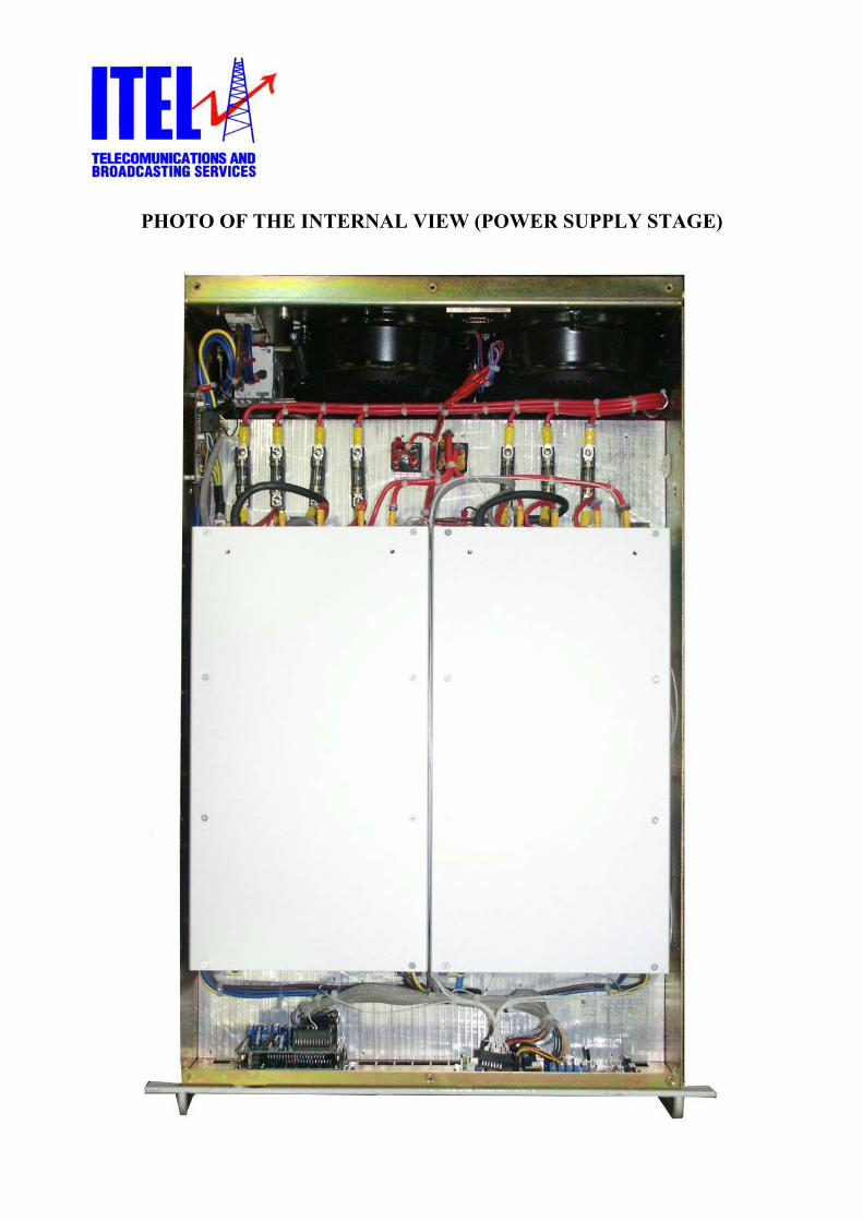
PHOTO OF THE INTERNAL VIEW (POWER SUPPLY STAGE)

TAU 1000 LD AMPLIFIER

TAU 1000 LD AMPLIFIER FRONT VIEW
1) RF Input N connector 6) Overdrive LED indicator 2) Measure Instrument 7) VSWR LED indicator 3) Measure Select push button 8) Shut-down LED indicator 4) RF Monitor BNC connector 9) ON/OFF Main LED indicator 5) Overheat LED indicator

TAU 1000 LD AMPLIFIER REAR VIEW
1) ON/OFF Mains Switch 6) RF Output DIN 7/16” connector 2) RF Input N connector 7) Fan 3) AUX DB9 connector (Optional) 8) Fan 4) REMOTE DB9 connector (Optional) 9) Mains Power Supply Connector 5) ENABLE DB9 connector (Optional)

TAU 1000 LD AMPLIFIER TOP VIEW
1) Fan 6) Output coupler 2) RF Output DIN 7/16” connector 7) LD-MOS amplifier module 3) RF Input filter DIN 7/16” connector 8) 20 W p.s. driver module 4) Fan 9) Input Splitter 5) Output Bandpass-notch filter 10) LD-MOS amplifier module

TAU 1000 LD AMPLIFIER BOTTOM VIEW
1) Switching Power Supply Nr.1 3) Protections and logic boards 2) Switching Power Supply Nr.2 4) Measure Instrument boards

TAU 1000 LD BLOCK DIAGRAM