-TV - americanradiohistory.com€¦ · KTSM Radio, 1380 KC and KTSM -TV, Channel 9, asked for our...
32
KTSM -TV Ranger Peak El Paso, Texas sr VOL. NO. 109 SEPTEMBER 1960 www.americanradiohistory.com
Transcript of -TV - americanradiohistory.com€¦ · KTSM Radio, 1380 KC and KTSM -TV, Channel 9, asked for our...

KTSM -TV Ranger Peak
El Paso, Texas
sr VOL. NO. 109 SEPTEMBER 1960
www.americanradiohistory.com

RCA's NEW
1KW FM
Transmitter ideai mice tor
truly economical
FM operation !
SINGLE TUBE POWER AMPLIFIER keeps operating costs low. Actually there are only three basic elements in this new 1 KW trans- mitter: the standard RCA FM exciter, the power supply, and the single PA stage. Com- bined with RCA's complete line of FM an- tennas, the BTF -1D should be your first choice for truly economical FM operation.
STEREO MULTIPLEXING or dual subchannel operations are economically obtained by add- ing RCA subcarrier generators. The BTF -1D always produces a full fidelity signal with low distortion and noise for both conventional and multiplex operation.
A BUILDING BLOCK UNIT, this new 1 KW transmitter can easily be expanded to 5, 10, or 20 KW just by adding higher power amplifiers.
YOUR NEAREST RCA BROADCAST REPRE- SENTATIVE will gladly help you select the best equipment for your installation. See him for the details, or write to RCA, Dept. KC -22. Broadcast and Television Equipment, Build- ing 15 -1, Camden, New Jersey.
EASY TO SERVICE: Easy access to all components from front and rear. The exciter unit tilts out as shown from the front to expose all components. All tuning controls are on the right front panel.
The Most Trusted Name in Electronics RADIO CORPORATION OF AMERICA
www.americanradiohistory.com

Vol. No. 109 September, 1960
BROADCAST NEWS published by
RADIO CORPORATION OF AMERICA BROADCAST & TELEVISION EQUIPMENT DIVISION
CAMDEN. NEW JERSEY
issued quarterly
in U.S.A. $4.00 for 4 issues PRICE
outride U.S.A. - - - $5.00 for 4 issues
C O N T E N T S
Page
KTSM -TV MOUNTAIN -TOP TRANSMITTER . 5
AUTOMATIC FILM SELECTOR AT WKRC -TV . 8
NEW 16 -INCH TURNTABLE 10
NEW SEMICONDUCTOR POWER SUPPLY . 12
THREE NEW TRANSMITTERS FOR THOMS RADIO . 13
NEW HIGH FIDELITY VOICE FOR KGBX . 13
KSTP -TV LAUNCHES MODERNIZATION PROGRAM 14
MOBILE TV TAPE OPENS NEW SALES FOR KRGV -TV . . 16
SKELTON RED -EO -TAPE MOBILE TV SYSTEM 18
COLOR TV MOVES FORWARD . . 22
REPLACEMENT PARTS DEPT. HELPS KEEP STATIONS ON -AIR . . 24
Copyright 190. all Rights R.serred
Trademarkls) Q Registered..11arralai Registraduisi Radio Corporation of Amerirn. Broadens, & Television Equipment Division. Camden, N. J.
p...reo a4r-
www.americanradiohistory.com

NEW Look! NEW Picture Quality! NEW 41/2 inch I.O.
... the First All -New TV Studio Camera in 8 Years! RCA's new monochrome television camera Type TK -12 is new in every sense of the word
. including startling new improvements in picture quality, significant new savings in operating costs and manpower, new features that help you sell!
41/2 INCH IMAGE ORTHICON. This new camera uses a larger image orthicon picture tube -4% inches in diameter. The 50 per cent greater tube size makes it possible to obtain far better picture detail than has been possible before.
FUNCTIONAL STYLING. A "new look" to identify this camera with the "new picture" has been given the TK -12, in the form of a distinguishing keystone shape. Functional in advantage, too, it provides space for an 8% inch view finder instead of the usual 5 or 7 inch.
NEW SAVINGS IN OPERATION. High stability and reliability coupled with a brand new control concept, permit a single video operator to handle as many as six cameras. For the normal run he need be concerned with only two operating controls per camera.
ONE MINUTE WARM -UP. Camera set -up is the easiest ever! Turn it on and in one minute the picture is there. Quality pictures "snap in" each time you turn on camera. THE BEST PICTURE IN TOWN! The extremely sharp picture, the beautiful rendition of gray scale and freedom from halo effect make this camera ideal for both "live" broadcast and TV tape recording.
Ask your RCA Representative for complete information. Or write to RCA, Broadcast and Television Equipment Division, Dept. H -264, Building 15-1, Camden, N.J.
The Most Trusted Name in Electronics RADIO CORPORATION OF AMERICA
www.americanradiohistory.com

MICROPHONES -a type for every requirement Check your microphone requirements, today. Do you have one for each purpose - remotes, an- nounce, interviews, boom, general purpose? Use the handy order coupon to order any microphones you need.
FINEST QUALITY MICROPHONE
Standard microphone of the industry, the
RCA 77 -DX offers full range frequency response
with a choice of three pickup patterns. Avail-
able in a satin chrome finish for radio and a
low gloss gray for TV, it will offer years of
rugged dependable service. $180
PERSONAL MICROPHONE
Ideal for Remotes
Wherever a small inconspicuous microphone is
needed the BK -6B can be used. This 2.3 ounce
unit offers excellent reproduction for every
speech application both in the studio and in
the field. $82.5°
HIGH -FIDELITY UTILITY MICROPHONES
General purpose BK -11A microphone is the
modern version of the very famous 44 -BX. It
is ideal for every studio use, especially live
music pickup. The BK -11A is an economical high performance unit designed for years of
rugged service. $125
NOISE -REDUCING BOOM MICROPHONE
Here is the highly directional BK -5A micro-
phone for TV boom use. Its pickup pattern
effectively reduces noise while offering full range highest quality pickup of the desired source. The BK -5A is also an excellent choice
for control room use. $165
COMMENTATOR MICROPHONE
The BK -lA is a fine microphone for interviews.
panel shows, and all general announce work.
Its rugged construction and insensitivity to wind and mechanical vibration make the BK -lA ideal for outdoor remotes. $75
ORDER NOW BY MAIL!
Order any of these five microphones for prompt delivery.
Send cheek or money order with your order and micro- phones will be shipped prepaid. Mail your order to RCA,
Audio Sales, Broadcast and Television Equipment Division, Building 15 -6, Camden, N.J. Use coupon below.
p PIThe Most Trusted Name viiikIn Electronics
7 RADIO CORPORATION OF AMERICA
RCA, Audio Sales, Broadcast and Television Equipment Division, Dept. MC -22 Building 15 -6, Camden, N.J.
Please send the units checked. Check enclosed
77 -DX BK -6B BK -11A BK -IA BK -5A
Send to
Address
City Zone State
Enclose remittance with order and save shipping charges.
www.americanradiohistory.com

COMPACT TT -11AH TRANSMITTER
Features of the RCA 11 KW VHF Transmitter that
have clicked with engineers and managers (features that make it easy to operate and improve performance)
1. UP TO 180,000 WATTS E.R.P. -when combined with an RCA high -gain antenna. Channels 7 -13. Or can be used as a driver to obtain higher power.
2. WALK -IN DESIGN ACCESSIBILITY- Improved walk -in design, introduced with the TT -2BL and TT -6AL Trans- mitters, is an invaluable feature of the TT -11AH. A wide aisle is provided inside the enclosure between the front -line racks and power supply components to the rear. All corn - ponents are readily accessible from this aisle.
3. TUNING SIMPLICITY -All tuning adjustments can be made from the front of the transmitter with power applied. Power amplifier cavity has been greatly simplified, and no change in frequency -determining components is required to tune to any high -band VHF channel.
4. WIDE AMBIENT TEMPERATURE RANGE - Operation over a wide ambient temperature range is provided by thermo- statically controlled cooling of all mercury-vapor recti- fier tubes.
5. QUIET OPERATION -All tubes and components, other than the mercury -vapor rectifier tubes, are cooled by one main blower in a sound -insulated enclosure.
6. OVERLOAD PROTECTION prevents extensive damage in case of circuit fault. If overload is momentary, operation is immediately restored while light remains on to indicate point of overload.
7. DESIGNED FOR REMOTE CONTROL- Provisions have been made for remote metering and control of all necessary functions from a remote point. These facilities may also be used to control the transmitter from a central point in the transmitter building.
8. FEWER TUBES AND COMPONENTS TO STOCK -Fewer spare tubes and components need be stocked since the same tube types are used in both aural and visual rf chains.
ILLUMINATED METERS -A row of large illuminated meters, mounted on a sloping -front panel for ease of reading, shows all important currents and voltages.
lo. IMPROVED COLOR PERFORMANCE - Built -in linearity correction, accurate intercarrier frequency control, and dc on power amplifier filaments are features included for out- standing color performance.
9.
Get the complete story from your RCA Broadcast representative; or write for descriptive literature to RCA, Dept. MD-22, Building 15 -1, Camden, N. J. In Canada: RCA VICTOR Company Limited, Montreal
RCA Broadcast and Television Equipment, Camden, N. J. J The Most Trusted Name in Television RADIO CORPORATION OF AMERICA
www.americanradiohistory.com

RANGER PEAK! North latitude 31 de- grees, 48 minutes, 18 seconds: West longi- tude 106 degrees, 28 minutes, 57 seconds. One mile northwest of El Paso, Texas and three miles north of Juarez, Old Mexico. A
rough, rocky pinnacle of the Franklin Mountains, elevation 5630 feet above sea level, approximately 1900 feet above aver- age terrain. To reach the top you climb - wearing good heavy shoes.
The above statistics were well known to the staff of KTSM -TV, Channel 9. El Paso and caused many hours of discussion con- cerning "How are we going to build our new transmitter building and erect a tower?" Yet, we knew we were going to do it, and we did.
It would be difficult to find a place that could impose more natural obstructions in the path of normal construction of any type of building. The peak rose at the apex of three rock "hog- back" ridges, with al- most sheer fall away on all sides. On this point the C.A.A. had installed a small tri- angular steel house approximately ten feet
FIG. 1. Transmitter building and tower of KTSM -TV. atop Ranger Peak, El Paso, Texas.
KTS M -TV MOUNTAIN -TOP
TRANSMITTER AT EL PASO
by DEAN SPIRES Transmitter Plant Supervisor, Tri -State Broadcasting Company
on each side, which supported an air -ways beacon, with little room left over.
For almost two years we had been draw- ing plans for the new transmitter building, trying to incorporate every possible con- venience and necessity, taking advantage of our experience in the old location. We were determined that we would allow no dirt or dust to enter the building, that noises from blowers and exhaust fans would be cut to the minimum, that ample heating and cooling equipment would be on hand, so that we could install, at any time, any type of amplifier we might decide on with- out moving any of the equipment in use. This we can do.
The engineers have been provided with every comfort and convenience. Sleeping facilities in case of a bad storm, kitchen with oven and grill, freezer compartment, hot water and survival ration in case one has to spend a few days and nights by himself and if this were not enough, he can enjoy the companionship of "Buford," a young black tom cat who has moved in with us and lives high on Ranger Peak.
Mr. Karl O. Wyler, Sr., President and Owner of Tri -State Broadcasting Company, KTSM Radio, 1380 KC and KTSM -TV, Channel 9, asked for our plans early this year and we were ready for him. After the smoke cleared away and after a few minor concessions on our part, we came to an agreement and our rough drafts were sub- mitted to the architect.
Briefly, the building was to be two stories, steel girder construction, stressed
to allow the addition of a third story, 32 feet wide, 36 feet in length, overhead clear- ance in the first floor minimum of 8 feet, overhead clearance of 12% feet on the second floor. An overhanging observation walkway extends around three sides of the building and affords a breath -taking view of El Paso, Juarez, surrounding smaller cities and almost a hundred miles in all directions, encompassing New Mexico, Texas, Arizona and Old Mexico.
Now we were getting somewhere, well almost, we needed room to erect a 300 foot Ideco self -supporting tower, base spread of 24 feet, 11 inches, three legged. It didn't require the services of a mathematical wizard for us to see that there was no room on Ranger Peak for such an installation as this but we were already committed so nothing to do but dig and gouge and blast off the top of the mountain, without benefit of heavy equipment and we could not use too much dynamite at a time because of one part of our project which was almost completed.
Most amazing and gratifying was the achievement of the Herron Engineering Company of Denver, Colorado, that de- signed and installed the aerial tramway. This was and is our sole means of trans- portation to the top of Ranger Peak. When we stop to realize that the pay load of the original work car was somewhere around 1800 pounds, it can be readily seen that construction of the building with the additional factor of transporting workmen took lots of time, so we set no speed records.
5
www.americanradiohistory.com

FIG. 2. Author Dean Spires, transmitter supervisor in control room of TT -10AH TV Transmitter, note official station mascot. "Buford."
There is no water on Ranger Peak, ex- cept that which is hauled up in 55 gallon drums and dumped into a 1000 gallon stor- age tank. A pressure pump system feeds the plumbing and toilet facilities for both engineering and visiting personnel.
Another item which consumed time was the digging, by hand (with an occasional half stick of dynamite to help) the holes in solid rock for the tower footings. So easy to write, so heartbreaking to watch, the
slow, laborious gouging out of rock as the men work in these holes -heat and rock dust their ever present companions. How- ever, as Horatio Alger said "Where there is a will there is a way," and the Ideco stands true and beautiful with its crowning glory, the RCA Traveling Wave Antenna, Type TW -9A9.
With the building almost finished and tower footings ready and cured, we awaited the arrival of Paul Tiner and crew from
FIG. 3. The peak of the mountain was blasted off to provide room for the building and tower.
FIG. 4. Typical construction scene while trans- mitter building was being constructed.
the Seago Construction Company, who were to erect the tower. These gentlemen were delayed somewhat, by a previous engage- ment and the intervening time was well put to use in finishing the building and installing our RCA Microwave link be- tween the studio and Ranger Peak, a nice clear shot, all down hill.
Paul Tiner and crew arrived and found a couple of small problems to overcome. The tower and antenna were 3000 feet away
www.americanradiohistory.com

FIG. 5. Radio services area of KTSM.
from the tower footings, down the side of the mountain. There was no way of getting a hoist on top of the mountain due to exces- sive weight and no place to put it if you could have managed to get it there. Again we witnessed the almost uncanny skill and ingenuity of men of such caliber as these.
The big winch was positioned alongside the tramway tower base station and a half inch line was pulled to the top, looped through the gin pole and associated gear and back down to the bottom. Additional pulleys were installed on the tramway run
cable to equalize weight, and tower sections were pulled to the top and erected by the use of the bottom winch and an intercom.
Considering the fact that these cables were at times in free space and at other times dragging through rock and sage brush down the side of the mountain it speaks well for the skill of men who can raise or drop a few thousand pounds to position them with only a "whoop- whoop" as their guide -they were unable to see the crew on top. Cold and high winds through- out erection did not help.
FIG. S. Riding through the sky to the KTSM transmitter. This tramway is the sole means of transpor- tation for water and other supplies. station personnel and visitors.
The antenna sections were hoisted sepa- rately, assembled at the tower base and hoisted as one section to the top of the tower and set in place, just as easy as pie, mind you, and from 3000 feet away, down- hill almost out of sight. What great credit Tiner and his crew deserve.
We were all set with an interim Trans- mitter, a TT -500B, our microwave working, program line ready to go and a new 50 -kw filterplexer waiting for the 65/s -inch trans- mission line and on December 13, 1959 we went on the air with programming from Ranger Peak.
Two days after regular programming with the TT -500B we started to dismantle the TT -10AH and by the combined efforts of all the engineering staff of KTSM we moved it up on the mountain, assembled it and went on the air with regular program- ming December 29, 1959.
Our coverage is exceeding expectations and we are proud that we can bring NBC to many areas within 200 miles of El Paso that have not had this service previously.
Mr. Karl O. Wyler, Sr., President and Mr. Karl O. "Bucko" Wyler, Jr., Vice President. who was the ramrod of "Project Ranger Peak," and the staff of KTSM -TV wish to thank all those who helped us in our planning and building of this new facility. RCA Personnel who have been most courteous and helpful are Jim Bar- clay, Bob Martin, Gene Clark, Cliff Ellis and many others.
7
www.americanradiohistory.com

AUTOMATIC FILM
SELECTOR by AL SALT Engineering
The Automatic Film Selector is designed to operate with an RCA TP -6C Film Pro- jector modified with the "Auto Cue" system and the continuous film loop attachment, see Fig. 1. The primary function of the selector is to count the number of film spots or events on the loop and by pre- selection determine the event to be stopped at the film gate. A total of nine spots can be accommodated by the system.
Description
The "Auto Film Selector" is comprised of three separate units (see Fig. 2):
1. A buffer relay unit (K -I ), 2. A remote control panel, and 3. A ten position stepper relay (K -2) .
The buffer relay unit consists of a slow - release relay, a manual -auto switch and a suitable terminal strip for external wiring.
The remote control unit has three con- trols plus the digital readout unit, see Fig.
ENABLES STATION TO PRE - SELECT SPOTS ON CONTINUOUS LOOP PROJECTOR
Staff, WKRC -TV, Taft Broadcasting Company, Cincinnati, Ohio
4. Reading from left to right: Item 3, S2
film selector, Item 2 digital readout, Item 10, S3 zero set, and Item 4, S4 the total film selector.
The ten position stepper relay, Item 1,
see Fig. 5, was chosen to go with the digital readout unit and after months of operation this choice has proved satisfac- tory. A bridge type rectifier was built (using Items 8 and 9) to supply voltage to energize the solenoid, and was mounted on dust cover of relay. This separate supply isolated the automatic control unit from the control circuits of the TP -6.
Installation The buffer relay unit is located to the
right of the pre -amp power supply in the base of the TP -6 Projector. (The slow release type of relay was chosen as the buffer relay to eliminate any chance of chattering due to faulty cue tape or cue sensing roller contacts and to further iso- late this automatic system.)
FIG. 1. Author, Al Salt, at Continuous Loop attachment of TP-6 Film Projector. The Continuous Loop of Film consists of a number of spots spliced together. Each spot can be called for separately by the system.
BUFFER RELAY UNIT K-I
The remote control panel is located near the master control console. It provides com- plete control of the film selector.
The stepper relay is installed within several feet of the remote control unit. This nearness cuts down loss in the multiple wire cable between these two units.
Operation The film for the continuous loop attach-
ment is prepared in the normal manner, having a metallic cue tape several frames in front of the start of each separate film event. An additional cue tape is placed in the interval between the end of the last film and the first cue tape. This additional tape advances the stepper relay to the zero position after a full rotation of the loop.
As each metallic cue tape makes contact with the cue sensing roller, the buffer relay (K -1) is energized and thru its contacts 1 and 2 applies 24 volts dc to the rotor contacts of decks A and B of the stepper relay (K -2), see Fig. 2. Contacts 3 and 4 of K -1 complete the circuit of the K -2
solenoid putting the stepper relay in cocked position. The auto /manual switch also re- ceives this pulse of energy from the cue
STEPPER RELAY UNIT K-2
CUE TAPE
AUTO
TB-101
S -I
MANUAL
S-2
150V.AC MIN. 250V.AC MAX.
C
2 3 4 5 e 7 B
9 o
DIGITAL READOUT
REMOTE CONTROL UNIT FIG. 2. Schematic diagram of the Automatic Continuous Loop Film Selector System.
www.americanradiohistory.com
ORIGINAL WIRING e 24V0 O C 0TD 101
OC CUE SENSING OF ROLLER CONTACTS TP -6C
*24V DC
AUTOMATIC WIRING
51
-24VDC
AUTO TB-101-4
ANUAL
32
oho á '
FILM SELECTOR
CONTACTS ON STEPPER RELAY DECKS A t B
FIG. 3. Simplified drawing of wiring changes to accommodate Automatic Selector in the Continuous Loop System.
sensing roller and can either return the circuit to normal (the on or closed position manual) or automatic (the off or opened position) .
As the tape leaves the sensing roller as- sembly, K -1 and K -2 are deenergized, causing K -2 to step (or rotate) to next position. As each step is made the proper number appears on the digital readout through contacts on deck "C" of stepper relay.
When coincidence. between the number of the film event selected and number of steps K -2 has taken, arrives once again the circuit is complete to operate the brake system of the projector.
Note on Fig. 2 that the rotor or common contact of decks D and E return to the self -interruptor contacts of K -2. 'Thus. when S3 is pressed the stepper rotates until the circuit is broken at the tenth or zero position of the stepper relay.
The film selector limit switch S4 works in the same manner as above. S4. however, selects the number of events or steps to be by- passed to bring the counter back to zero.
FIG. This
4. Remote Control Unit for the Automatic Film Selector. remote panel is Installed in master control console.
Set -Up Procedure
The complete procedure for setting up the TP -6 Projector with Continuous Loop attachment for Automatic Film Selection is as follows:
I. Load projector normally, seeing that the stop tape of film No. 1 is outside the contacts of the Cue Sensing Roller Assembly. Add an extra stop tape after the last film on the loop.
2. "Zero Set" by pressing S2 on Remote Control Panel. Zero will show on digi- tal readout.
3. Set the Film Selector Limit (S4) on Control Panel for total number of events on loop (maximum of nine).
4. Select the event to be shown first (1 thru 9) by rotating Film Selector Control (S2) to proper number.
5. Manually roll projector. It will stop on proper film and the number of this film will show on readout.
6. As first selected film comes to a stop, the next event should be selected. If the next spot is not selected at this time the projector will stop automati-
FIG. 5. Ten position stepper relay employed with digital readout unit of Automatic Film Selector. This relay is installed near the remote control unit.
E Q U I P M E N T L I S T
Item Description
1 Ten position spring loaded stepper relay (Automatic SPW- 56400.1
2 Digital Readout Model SGS -101 made by I.D.E.A., Inc.
3 Single Pole -Ten Position Rotary Switch (CentraLab)
4 Ten Position Progressively Shorting Rotory Switch (CentraLab)
.5 Isolation Transformer (Stancor) 115V. Pri. -250V. Sec.
6 Buffer Relay -Slow Release Type (Automatic Relay íPE- 116 -B31)
7 Single Pole Single Throw Toggle Switch
8 Transformer 115V. Pri. -30V. Sec.
9 Bridge Rectifier (Selenium)
10 Single Pole Momentary Switch
cally with next stop tape. This is a safety feature, for if the unit is not supplied each time with new or differ- ent information the projector would run for a full revolution needlessly.
Saves Time and Film
The Automatic Film Selector has now been in operation at WKRC -TV for several months. Results have proved the effective- ness of the installation. It enables the Con- tinuous Loop System to handle as many as nine commercials, requiring only one print of each for repeat showings. Thus, it saves film prints as well as a great deal of time and effort on behalf of station personnel.
9
www.americanradiohistory.com

NEW 16 -INCH TURNTABLE FEATURES IMPROVED IDLER ARM ASSEMBLY
FOR SMOOTHER AND FASTER STARTING
The BQ -2C Transcription Turntable, new- est in the RCA series is a three -speed, rim -drive type mechanism. It meets all the requirements of the broadcaster for a dependable, quiet operating, professional turntable. It will handle all types of disc recordings -331/3, 45, and 78 rpm -up to 16 inches in diameter. Fast starting and speed switching make the BQ -2C ideal for fast -paced radio programming -where highest quality reproduction is demanded.
Improved Performance Many new performance features put the
BQ -2C far ahead of most similar turn- table units. Only two controls are used a three -position speed selection switch, which
by ROBERT REYNOLDS Broadcast Audio Marketing
may be changed to any of the three speeds even with the turntable running, and an "On -Off" selector switch which controls the motor and engages or disengages the idler wheels. Extensive adjustments of idler arm tension springs and idler wheel alignments are not required. A snap -up spindle is located at the center of the sturdy 14 -pound turntable platter for 45 rpm operation, thus assuring ease of record handling and proper centering. Custom installations are easy, since the entire mechanism is contained on a single metal plate. 18 inches square. A mounting tem- plate for this purpose is provided with each unit.
Distinctive Feature The new model while retaining all the
desirable features of its predecessors, has an improved idler arm assembly which as- sures extremely smooth starts, so necessary when playing microgroove records. The new idler arms have stop adjustments fastened to them, that permit the idler puck arms to be aligned individually, with the cap- stan shaft. In addition, the puck arms have tension applied at all times by springs.
Rugged Mechanism The heart of the BQ -2C is the heavy -
duty hysteresis- synchronous motor with its one piece, three -step diameter motor capstan shaft. This method of capstan construction practically eliminates all pos- sibility of flutter, usually associated with multi -piece capstan shafts. Large size idler wheels, made of a special compound for trouble -free life, engage the capstan shaft and the platter rim in the play position. In the off position, the idlers are disengaged thus avoiding "flats". Since turntable speed
10
FIG. 1. Heavy cast aluminum platter of the BQ- 2C is supported by this mounting plate that also supports the drive motor.
FIG. 2. The BQ -2C housed in its rugged fabrikoid covered cabinet. All operating controls of the 13Q-2C are conveniently mounted for easy opera- tion. Space is provided for mounting a BA -26A Transistor Preamplifier and its control can be seen just below the pickup.
www.americanradiohistory.com

FIG. 3. Typical Installation of several BQ -2C's gives a custom look to the studio.
is determined only by the ratio of diameter between the motor capstan and the platter rim, speed will not vary in this turntable even when continuous wear reduces the size of the idler wheels. Full speed is reached within one -half turn at 33'/1 and 45 rpm, and within three- quarters of a turn at 78 rpm.
Accessible Cabinet
An attractive modern cabinet is provided to house the BQ -2C. This wooden console
has a durable, two -tone umber gray fabri- koid covering on the sides and a cigarette - proof linoleum top. Any type of standard broadcast tone arms may be easily mounted on the cabinet and adequate space is avail- able for mounting two tone arms for various types of pickups. The BA -26A transistorized, equalizer- preamplifier is also readily accommodated in this cabinet.
Updating Previous Models
A modification kit. MI- 11440, containing
three of the new "C" idler arm assemblies plus the necessary instructions is available to those who wish to update earlier models. Owners of previous models may obtain these kits on a no- charge basis, F.O.B. Camden, New Jersey by simply sending the serial number of each BQ -2A or BQ -2B turntable and mailing it to the nearest RCA Broadcast Equipment Representa- tive. Or the information may be sent di- rectly to RCA, Broadcast Audio Sales, Building 15 -6, Camden, New Jersey.
FIG. 4. Close -up of the new idler wheel assem bly. Tension springs have been designed to oper- ate with little or no adjustment.
11
www.americanradiohistory.com

NEW SEMICONDUCTOR POWER SUPPLY IS SPACE
AND POWER SAVER Significant reductions in space, power and heat dissipation are now possible in a new Semiconductor Power Supply, Type WP- 16. The chassis occupies only seven inches of rack space, so that eleven power supplies can be mounted in a standard cabinet rack. No blower is included in the power supply; the small amount of heat generated being carried away by convection cooling in a large heat sink. The equipment is rated at 1600 milliamperes and serves as a power source for almost any equipment requiring regulated 280 volt d -c power.
Single Unit Powers Complete Monochrome Camera Chain
The V1' -16 can be used as a direct re- placement for existing power supplies with a substantial saving in space, weight, power consumption and heat dissipation. Current requirements of an entire monochrome
Complete short circuit protection is also provided. If a short circuit occurs in the load, both voltage and current drop to zero and remain thus until the short is cleared, at which time the current and voltage are automatically restored to normal. A fuse in the primary of the power transformer is provided to protect the power supply from internal shorts.
Voltage -Regulating Power Transformer The heavy duty power transformer is
of the regulating type so that the voltage input to the rectifier is constant for a range of line voltage from 95 to 130 volts. An auxiliary winding which may be connected in series with the primary of the trans- former permits operation over a line volt- age range of 190 to 260 volts. The fre- quency tolerance is 60 cycles plus or minus 1 cycle per second.
FIG. 1. Compact new semicon- ductor power supply, type WP -16. occupies only 7 inches of rack space, provides 1600 milliamps. regulated 280 volt d -c output.
FIG. 2. Chart showing current capacity and mounting arrangement of WP-16 power supply as compared with earlier model WP -15 and WP -33B supplies.
camera chain, live or film, including the master monitor are accommodated by one WP -16 power supply. Two supplies per- form similar functions for color studio or color film camera chains.
Protection Circuits
Since a semiconductor power supply would normally make output voltage avail- able the instant the a -c power switch was thrown, a time delay relay is provided in the WP -16 to prevent the application of the plate voltage until the filaments of the powered equipment reach operating tem- perature. Should momentary power failure occur, the relay does not recycle; however, it will recycle and reintroduce time delay for failures of more than several seconds.
12
Plug -In Units for Centering and Unregulated Voltage Outputs
Centering current and unregulated volt- age are supplied by means of plug -in sub - chassis units which are powered by sepa- rate, non -regulating secondary windings of the power transformer. These units are normally required only when the WP -16 is used with a camera chain and need not be purchased when the supply is to be used for applications requiring only the regu- lated voltage output.
The Centering Current Plug -in Unit is used for supplying centering current for film and live cameras and master monitors. Current is adjustable between 300 and 1200 ma. by means of a control located on the front panel of the power supply.
The Unregulated Voltage Plug -in Unit is used for those applications requiring a higher voltage than that provided by the regulated voltage output, i.e., the deflection circuits of cameras and some types of master monitors. The plug -in unit and basic power supply are factory wired for an un- regulated d -c voltage output of 400 volts. Taps are provided on the power trans- former which can be connected to provide unregulated output voltages of 360, 380, 420 and 460 volts.
Power Supply of Many Uses The WP -16 is a rugged, high efficiency,
lightweight source of precisely regulated voltage capable of supplying current loads up to 1600 milliamperes. It weighs only 47 pounds, is 7 inches high, 19 inches wide, and 13/ inches deep. When used in tele- vision stations and closed- circuit installa- tions to replace existing power supplies, substantial savings in space, weight, power consumption and heat dissipation results.
W.16 POWER SUPPLY
N..1
No. 3
No. 3
No. 4
N.. 5
No. 6
No. r
N.. R
No. 9
N.. 10
No. 11
WP-15 POWER SUPPLY
REGULATOR N.. 1
REGULATOR N.. 1
REGULATOR Ne. S
REGULATOR No. 4
REGULATOR N.. S
RECTIFIER No. I
RECTIPIER No 3
RECTIFIER No. 3
RECTIFIER N. 4
RECTIFIER No. 5
MOUNTS I I IN SINGLE RACK NEAT DISSIPATION LIMITS S TO RACK
17,600 MA CAPACITY 7.500 MA CAPACITY
WP431 POWER SUPPLY
No. 1
N.. 2
N.. ]
N.. 4
No. S
MOUNTS S PER RACK
3M MA CAPACITY
www.americanradiohistory.com

3 NEW 5KW TRANSMITTERS FOR THOMS RADIO GROUP
Three stations owned by Thorns Radio - TV Enterprises, Inc., are now on the air with new type BTA -5R Transmitters. WCOG in Greensboro, N. C.. is operating its BTA-SR under the supervision of chief engineer Ansel Atkins. WAYS, Charlotte. N. C. went on the air under the direction of L. I. Dekle, chief engineer. All installa- tions were controlled by the skilled hands of John Randolph. technical director of Thorns Enterprises and chief engineer of WISE in Asheville, North Carolina.
Thorns Enterprises also owns WEAK, Arlington, Va., WMSJ, Sylva, N. C.; WKLM, Wilmington, N. C.; and WISE - TV in Asheville, N. C. Harold H. Thorns. president of the organization has recognized the need for transmission of the highest possible quality to the millions of listeners served by his stations. For most depend- able operation BTA -5R transmitters were selected. This choice was supported by all three chief engineers, each of whom has over 15 years of service with his station.
Chief Engineer L. I. Dekle of WAYS. Charlotte.
Chief Engineer Ansel Atkins of WCOG, Greensboro.
John Randolph. Chief Engineer of WISE, Asheville is also Technical Director for the Thorns Radio -TV Enterprises.
! .. J,irfìLlibt! ., .,
NEW HIGH FIDELITY VOICE KGBX Installs a New
5 KW Transmitter
On June 22 power was applied to a new BTA -5R Transmitter by Mayor David Scott of Springfield. Missouri. Don C. Dailey, General Manager of KGBX, dedi- cated the transmitter to community service.
With the new transmitter KGBX ex- pects to add many new listeners in Spring- field and the surrounding Ozarks. Like most modern stations KGBX provides strong high fidelity signal to every listener. KGBX now has a modern transmitter that is an ideal combination with the modern program format of the station.
FOR THE OZARKS
Present at the RGBX Dedication were left to righ : KGBX Program Director Jerry Higley. Chamber of Commerce Manager Ralph Powell, Chief Engineer Richard Bowman, Mayor David Scott and Springfield's City Manager Tom Chenoweth.
13
www.americanradiohistory.com

KSTP -TV LAUNCHES COMPREHENSIVE MODERNIZATION PROGRAM
Most Advanced Television Equipment, Including
Full Color Facilities, Installed at Central Location,
Promises New Era of Efficiency and Effectiveness
KSTP -TV, television broadcasting pio- neer and a recognized leader in the indus- try, has launched a broad range program to give the Minneapolis -St. Paul station a full array of the latest technical equipment housed in expanded quarters.
Stanley E. Hubbard, KSTP President, has announced that KSTP -TV plans call for an RCA "package" of the most ad- vanced television broadcasting equipment. This includes a station break automation system, TV tape recorders, complete color facilities, transistorized switching equip- ment and mobile production facilities capa- ble of handling both color or black -and- white remote programs.
Centralization of Equipment for Operations Efficiency
Working closely with the KSTP-TV engi- neering staff, RCA engineers helped draw up plans for an integrated layout which features the centralization of all equipment, including master control, studio, film and transmitter, in one area for greater operat- ing efficiency.
KSTP -TV was one of the first major television stations on the air, serving the Twin City area since 1948. Since then, the expansion of broadcasting activities was accompanied by the same sort of technical growing pains experienced by many sta- tions. As new equipment was needed and
acquired, it had to be placed where space was available. The end result was a loose - knit operation with master control in one room, film handling equipment in another and so on.
RCA system specialists were asked to work with the KSTP engineering staff to develop a master plan for overcoming the obvious inefficiencies of the previous setup. It was determined that, by centralization of technical equipment in an expanded facility, the station would be able to oper- ate at a far higher level of efficiency. De- tails of this centralized technical operation should prove of interest to other broad- casters, who may face a similar situation.
14
www.americanradiohistory.com
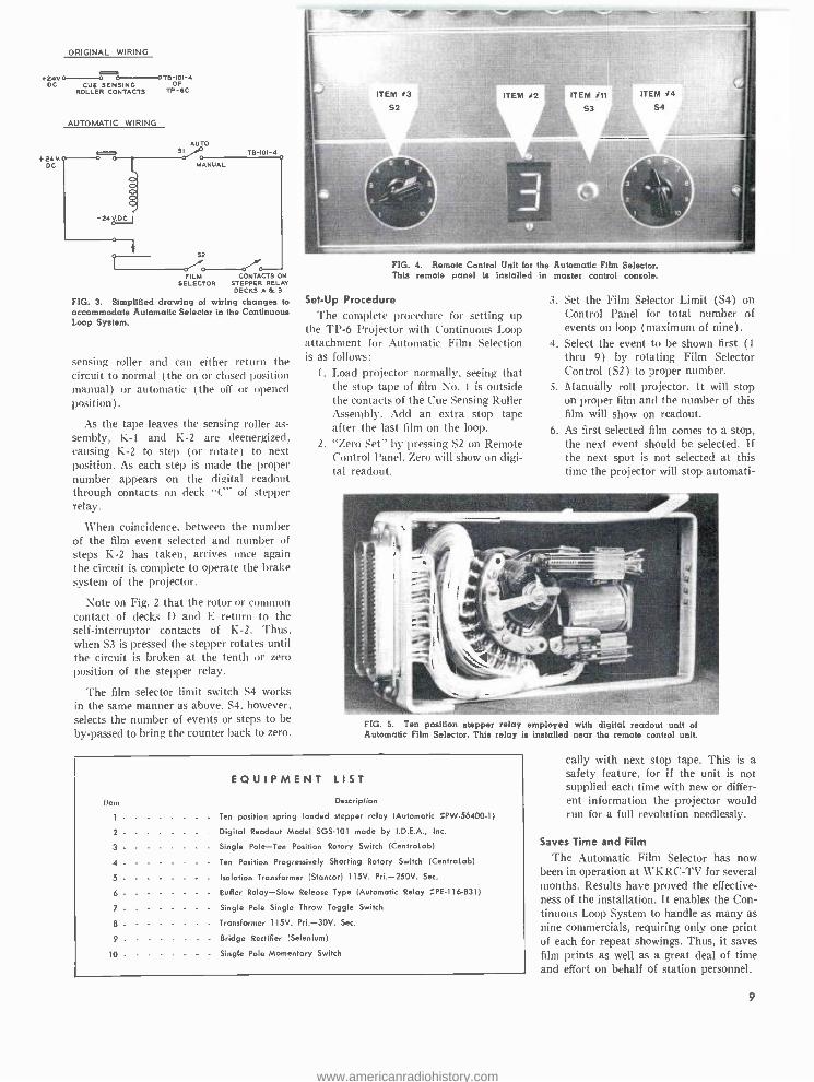
Equipment Central and Studios
The KSTP -TV "equipment central" will be a 60 by 80 -foot room in a new addition to the present station building. Ground has been broken for this addition which also will house a 40 by 60 -foot color studio. This is designed for a live audience, with air conditioning to take care of 200 people and 100,000 watts of lighting.
The studio is of sufficient height and equipped with catwalks for flying scenery, handling spots and so forth. It contains special acoustic paneling which serves the additional purpose of housing color moni- tors and high fidelity speakers.
The floor is of a new composition ter- razzo with acoustical concrete base. It will be noiseless and present no problems in cleaning. Underneath the studio floor is special steel trenching for carrying camera cables to various parts of the studio to avoid camera cables across the floor.
The new addition is to be equipped with electronic air filters to keep the operating area dust free and to reduce maintenance. The transmitter area will be on a closed-' air cycle with 32 tons of refrigeration so as to provide uniform temperature throughout the year. From preliminary tests it was determined that tube life could be extended 50 per cent by completely air conditioning the transmitter. The air conditioning will have a 100 per cent spare in case of failure of one unit.
The station modernization plan also calls for re- equipping the existing 50 by 60 -foot "Studio F." Special studio facilities to stage closed circuit TV presentations for audiences up to 300 persons will be in- cluded. Strategically located monitors will bring each individual within easy viewing range.
Station -Break Automation System
KSTP -TV will use an RCA Type TSA -2 automation system for handling up to a dozen events during a station break period. Activated by push button control, the auto- mation unit calls cameras, projectors, TV tape recorders and other equipment into play at the proper instant, according to a pre- determined sequence. This system takes pressure off studio personnel during the high -activity station break period, and as- sures the sponsor of dependable service.
The automation equipment will control a TS -40 transistor video switcher and an audio relay switcher which are located in master control. Two additional TS -40 switching systems will be installed in con- trol rooms for the individual studios.
Move to Live Color Addition of two TK -41 live color cam-
eras will implement KSTP -TV's film and network color schedule. The cameras will be equipped with new high- sensitivity image orthicons. These make possible fine color pictures with less studio lighting than heretofore possible.
Already equipped with film and slide units plus facilities to relay network color - casts, KSTP -TV will use the new cameras to engage in all forms of color TV pro- gramming. In addition, TV Tape Recorders at the station are equipped to handle color.
Color TV Mobile Units
Two KSTP-TV color cruisers are the latest design in mobile units. Equipped to accommodate four monochrome and two color cameras, the units are 35 feet long, 8 feet wide with full 7 -foot 2 -inch head room inside. Built -in microwave facilities, for color or monochrome, will relay remote pickups back to the station.
KSTP engineers have employed a unique cooling system in their mobile units. A chilled water system makes possible 72- degree inside temperature when the air out- side is 100 degrees and when five camera units and their attendant equipment is in operation. The use of chilled water elimi- nates the necessity for bulky air ducts saving considerable space. The cooling and heating is taken care of by three convector units installed out of the way in the ceiling. The heat transfer is accomplished by the use of three Trane convector units in- stalled in the ceiling. The mobile cruisers are fully insulated and the same convector units are used for heating in the winter time with below zero weather.
The mobile unit to house these facilities has already been completed, see Fig. 1. An accompanying mobile unit will contain the power plant and a battery of search -lights to illuminate disaster scenes or the sites of spot news developments. This contains 5 kw Kohler emergency generators which will take care of air conditioning and warm- ing of equipment and lighting the cruiser. Thus equipped. KSTP -TV will be able to further pursue their vigorous news, docu- mentary, and special events coverage of the Minneapolis -St. Paul scene.
New Monochrome Cameras
KSTP -TV also plans to use new RCA TK -12 monochrome cameras. with 4% -inch image orthicon pickup tubes to produce pictures of increased resolution and better gray scale rendition. Capable of producing high quality multiple generation tape copies. these new cameras will substantially improve TV tape production facilities.
Latest Design Transmitting Equipment
The KSTP -'TV transmitter will be mod- ernized by installing a new TT -6 driver unit for the RCA 25 kilowatt amplifier.
Measures have been taken to circumvent all possibilities of broadcast service inter- ruption. For example, the tower is equipped with two antennas and spare coaxial feed - lines so in case of an antenna failure an automatic transfer switch switches antennas in less than one second. Also, an RCA TT -2AL 2 kilowatt transmitter is main- tained in standby readiness at all times and will be automatically switched into service within two seconds should the main trans- mitter fail. Electrical service is received from two independent sources. Automatic power transfer switches will transfer the KSTP -TV load between the sources in 2/10 of a second.
Finest Service to Viewing Audience
The KSTP -TV engineering program represents an investment of $1,700,000. With this extensive equipment package in- stalled under the master plan prepared by station engineers and RCA, KSTP -TV will be in a position to provide finest tv broad- casting service to its viewing audience.
FILM AVAILABLE ON RCA TV TAPE RECORDER
Just released is a 16nun color movie show- ing the RCA TV Tape Recorder in action. This 1000 foot film describes RCA's con- clusive features and explains the resulting owner benefits. Moreover, it demonstrates exactly how the Tape Recorder should be operated.
Much of the film was shot in the RCA TV Tape demonstration area, Camden, N. J. Engineers who designed the recorder have also collaborated to explain the design advantages and demonstrate the proper use of the machine.
The art of making precision magnetic heads for tape recorders is given consider- able treatment. In addition, assembly and test procedures are shown. TV Tape splic- ing is graphically described in a sequence that reveals the techniques employed. Representative mobile and station instal- lations are portrayed in action.
The film is available for showing by RCA representatives to broadcasters, tv program and commercial producers, agen- cies. educational. and other potential users of TV Tape.
15
www.americanradiohistory.com

MOBILE TV TAPE UNIT OPENS UP NEW SALES WORLD FOR KRGV-TV
by HANK PAGE Sales Promotion Manager, KRGV -TV
For Television Station KRGV -TV, Rio Grande Valley, Weslaco, Texas . . . TV Tape has come through with an increasing number of answers to local television's pro- duction and sales problems.
By combining one of electronic's newest marvels with one of the world's first inven- tions ... the wheel ... KRGV-TV has become the first station in the Southwest to have a mobile tape unit and in doing so has created a vital force that is stimulating sales, improving production and adding an entire new dimension to local commercials and special event coverage.
Located in a 100,000 set, two station market, KRGV -TV has made its one RCA TV Tape Recorder do the job of two units.
Mobility A Must From the time KRGV -TV started think-
ing about tape, mobility seemed to be the only answer to the maze of problems spawned in the sprawling market of four counties and eighty communities comprised of some 400,000 people. After much re- search and study it was decided to put the RCA TV Tape Recorder in a trailer that could roll swiftly over the Valley's 1,700 miles of paved highways right to the client's door and to the far -flung sights of the area's many parades, celebrations and special events.
Custom Designed Trailer Unit
The specially designed and custom built trailer meets the requirements of allowing operators enough room to work and at the same time compacting equipment so that the trailer might be parked in a part of the station prop room where it can serve as a TV Tape room adjacent to the studio pro- jection room.
The trailer is of steel construction mounted on two aircraft wheels and axles. Each wheel is rated at a maximum of 5000 pounds; so no overweight problem is en- countered. The unit measures 10 feet long by 8 feet wide by 7 feet high. Three and one -half tons of air -conditioning are in- stalled and aided by two fans for effective air circulation. The equipment racks of the RCA recorder are located so that only 250 pounds loading is actually pushing down on the trailer hitch. When not in use, the mobile unit is jacked up on four corners in order to lighten the load on the wheels.
Saves Time and Expense on Remotes Time, demanding monster that it is in
broadcasting, is a key factor in setting up a remote taping session. Experience has proven that the actual set -up time is fan- tastically short. After arrival on the remote location, the tape unit is operative and re- cording in only 15 minutes. To anyone who ever worked on a remote microwave crew, building towers, making equipment alignments, etc. -this new method merits praise.
FIG. 1. The mobile TV tape unit, center, complements KRGV -TV's mobile television facili- ties making possible on the spot commercials throughout the station's service area. This point of sale convenience has attracted many new advertising accounts for the station.
16
The quality is outstanding and the over- all cost of mobile taping is less than a remote because of the elimination of the microwave hook -up.
The remote bus and cameras are "hot" and the first commercial rehearsed before the tape trailer arrives on location. This. of course, saves time, effort and MONEY.
FIG. 2. New tape spot business has resulted from installation of RCA TV Tape. Here the mobile unit is serving in its dual roll. pulled up outside the station projection room.
On- The -Spot Commercials Are Practical and Profitable
Judicious planning has made Mobile Tape location shooting of "on- the -spot" commercials ... both practical and profit- able. By planning ahead and leaving the studio at 5:00 a.m., KRGV -TV has thus far prevented themselves from being caught "with their tape pants down." The station is always ready to go live should the emer- gency arise; and since television managed to make it on a "live" basis for several years before Tape, the chance of doing it again is certainly anything but hazardous.
The spread -out geographical nature of the Rio Grande Valley, comprising the four southern -most counties of Texas has al- ways made it difficult and expensive for remote pick -ups because of the necessity of a microwave tower. KRGV -TV's Mobile Tape unit has now made frequent remotes possible.
www.americanradiohistory.com

Tape Commercials On- Location Bring in New Clients
The advantages of the Mobile Tape con- cept are many -fold and amazing. The sta- tion's account list has already grown because the new clients saw the first remote spots on the air and liked them. The key factor in the superiority of on- location commercials is . . , "PRESENCE" .. , the feeling of being right in the store, right at the moment the spot is airing. Then there is the added impact of the fact that a local station can do this at a cost the local mer- chant can afford.
KRGV -TV believes their location com- mercials have an increased believability, viewer acceptance and buyer association; and therefore do a better selling job for Valley business -men. Clients are impressed with the "authentic" nature of their com- mercials. Most important, the viewer -cus- tomer notices the commercials and goes out of his way to mention that he saw it.
It is pleasing to see the client reactions (especially the numerous employees who never participate in the buy) when the crews swarm over the place of business for
TWO COLOR TV TAPE INCREASE
3 to 4 hours literally taking over the place. They always ... without exception . . .
gain a healthier respect for TV people, the cost of TV recording and the complexities that are involved in putting together what they had regarded as a simple announce- ment. Clients are also impressed by the instantaneous play -back, especially when they take part in the commercial them- selves. Clients who have used Mobile Tape commercials have an understanding and appreciation of television that has never been possible before. They also have a de- sire to spend more.
RECORDERS With ith the addition of two new RCA Color TV Tape Recorders, WFBM -TV, Indian- apolis, has been able to step up its color - casting schedule by 30 per cent during the first six months of 1960.
WFBM-TV COLORCASTS
FIG. 1. Director of Engineering, Robert Flanders, punches the start button on one of WFBM -TV's two new RCA Color Television Tape Machines. Bob Brockway, Chief Engineer -Technical, who supervised the installation of the machines, looks on.
TvB TO INSTALL TAPE IN NEW OFFICES
As a service to its members, advertisers, and agencies, the Television Bureau of Ad- vertising will install an RCA Color TV Tape Recorder at its new offices at One Rockefeller Plaza in New York.
Highlighted among the new facilities which give TvB double the space it form- erly occupied is a TV Tape room soon to be completed. This room will be available for member use in screening hometown programs, commercials, and market pre-
sentations for admen in New York. It will also be used by TvB's own salesmen for making sales presentations to advertisers and agencies.
1'he TV Tape Recorder will feed a closed- circuit system with color receivers placed at various points throughout the offices. The main presentation area is a 13 by 18 foot conference room which ac- commodates up to 30 people and may be divided into two rooms when desired.
Color highlights of this period included daily "Trackside" telecasts from the Indi- anapolis Motor Speedway during the entire month of May. More than a dozen 15- minute color shows were taped at the track for playback later in the evening. Also colorcast were highlights of the $50,000 Golf Tournament edited from complete color tape coverage of the three -day event.
The addition of color TV Tape completes the full color facilities of Indiana's pioneer color station -including live and film origi- nation and TV Tape Recording. WFBM - TV is the second TV station, exclusive of networks, to have in service two RCA Color TV Tape Recorders.
According to Eldon Campbell, General Manager and Vice President: "TV Tape has allowed us to increase our color pro- grams. Color taping has become routine. Reproduction is `live' quality."
FIG. I. Charles H. Colledge, Vice President, Broadcast and Television Equipment Division, and Norman E. Cash, President, Television Bureau of Advertising sign contracts for TvB's acquisition of Color TV Tape.
17
www.americanradiohistory.com

FIG. 1. Three Skelton RED-EC-TAPE Mobile Units. Control room bus is at left foreground. and the recording unit di- rectly behind. The power and equipment storage bus is at right.
SKELTON RED-EO-TAPE MOBILE TV SYSTEM Employs RCA Color and Monochrome TV Cameras Color Film Chain with 35 and 16mm Projectors
Transistorized Switching and Special Effects System
Built at a cost of $1,000,000, the most advanced mobile television units in exist- ence were displayed August 18 by Red Skelton. the genial comedian, at his Studios in Hollywood, Calif. The units comprise a complete and large -scale television studio on wheels, employing color, as well as monochrome, tape and film. Conceived by Skelton and engineered by Robert Cobler, Chief Engineer, and Rupert Goodspeed. Studio Director of Technical Operations, the units will not only serve Skelton Studios, but can travel virtually anywhere for location shooting.
The RED -EO -TAPE system consists of three units, each constructed in a 40 -foot
18
bus chassis custom built by Crown Coach Corporation of Los Angeles. The first unit is like the master control room in a tele- vision station. It is here that video and audio control, switching, special effects, and remote control are performed.
Facilities of the first unit include con- trols for three TK -41 live color cameras and three TK -11 monochrome cameras, and one TK -26 color film camera. There are also three color monitors and four mono- chrome monitors. In this unit, the switch- ing between cameras and insertion of film and tape sequences are accomplished. Also, special effects can be added to the show. Well over 100 effects can be created, in-
cluding fades, lap dissolves, wipes and color mattes.
The second mobile unit contains two tape recorders together with editing and splicing facilities. A complete film system is in- stalled for insertion of films and slides in the program. Included are 16 and 35mm film projectors, and a slide projector. They are remotely operated from the control room (Unit No. 1).
The third unit completes the RED -EO- TAPE system. In it are two 85,000 watt generators to supply all necessary power. In addition, there is storage space for color and monochrome cameras, cables, micro- phones, tripods. etc. A complete shop is
www.americanradiohistory.com

located in this unit to handle repairs when on location.
The three buses, constructed of alumi- num, are 40 feet long, 8 feet wide and 11 feet high. Each weighs, fully equipped, from 38,600 to 42,000 pounds. Featured in the buses are 12 -speed transmissions with special Crown air controls, and power steering. The units are completely air - conditioned both for personnel and elec- tronic equipment.
With the RED-ED-TAPE units, a com- plete television production can be recorded on tape from any location, without de- pendence on external equipment or per- sonnel. This "completeness" extends to such details as editing, sound dubbing, integration of film portions and titles.
FIG. 2. Ribbon cutting ceremony at Skelton Studios as RED-EC-TAPE units were put on dis- play for first time. Left to right: Ed Hilley, studio manager; Valentina Skelton; Mrs. Georgia Skel- ton; Charles Luftig, executive vice -president: and the genial comedian, Red Skelton.
FIG. 3. Red Skelton receives congratulations from Warren Charles, RCA representative in Hollywood. Between them is the TK -91 Color TV Camera installed in Skelton's mobile tape units. Three of these famous cameras make it possible for Skelton to tape color programs.
19
www.americanradiohistory.com
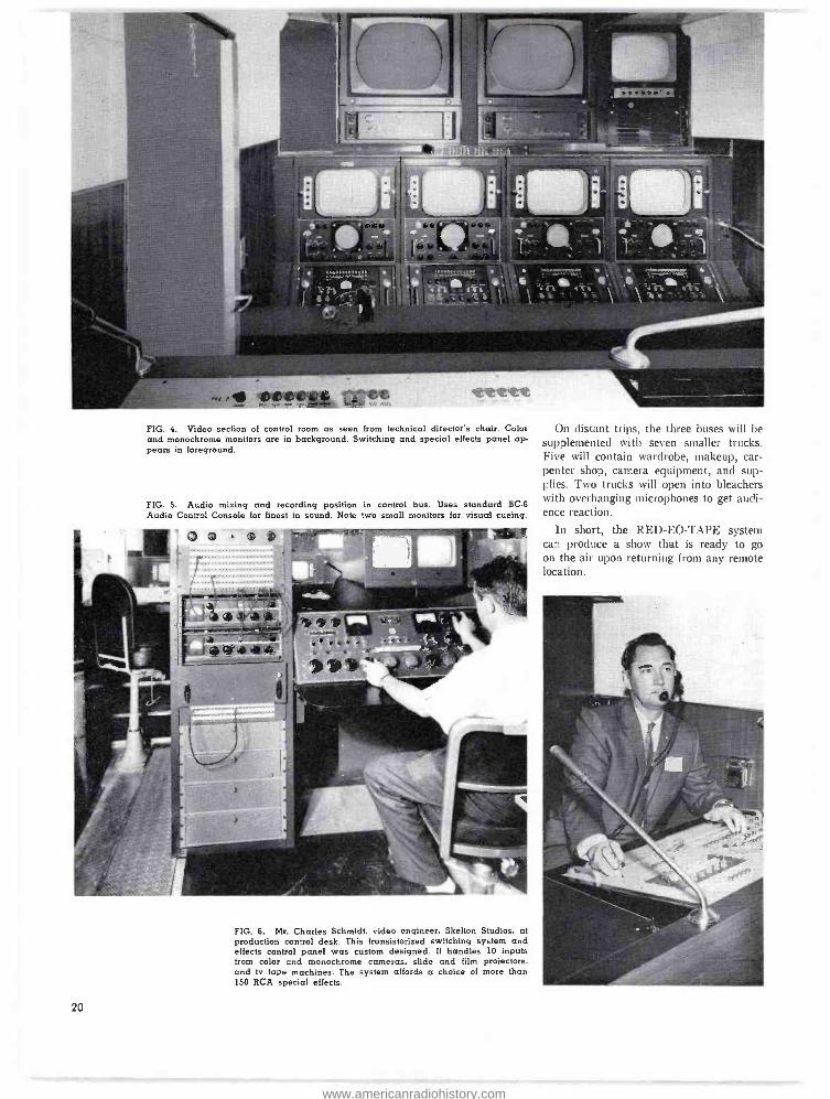
FIG. 4. Video section of control room as seen from technical director's chair. Colo! and monochrome monitors are in background. Switching and special effects panel ap- pears in foreground.
FIG. 5. Audio mixing and recording position in control bus. Uses standard BC -6
Audio Control Console for finest in sound. Note two small monitors for visual cueing.
On distant trips, the three buses will be supplemented with seven smaller trucks. Five will contain wardrobe, makeup, car- penter shop, camera equipment, and sup- plies. Two trucks will open into bleachers with overhanging microphones to get audi- ence reaction.
In short, the RED -EO -TAPE system can produce a show that is ready to go on the air upon returning from any remote location.
FIG. 6. Mr. Charles Schmidt, video engineer, Skelton Studios, at production control desk. This transistorized switching system and effects control panel was custom designed. It handles 10 inputs from color and monochrome cameras, slide and film projectors, and tv tape machines. The system at fords a choice of more than 150 RCA special effects.
20
www.americanradiohistory.com

FIG. 7. Note TK -4l Color Camera on hydraulically operated lift -gate. Cameras can also be hoisted to roof by means of built -in hydraulic hoist.
FIG. 8. Storage for television cameras, cables, and accessories. Note three TK -11 monochrome camera heads stacked at right.
FIG. 9. Complete color and monochrome film system is installed. This includes 35mm film projector, 16mm film projector, and a slide projector. Thus, stock footages and special film shots can be inserted into tv tapes. Equipment is remotely operated from control room.
21
www.americanradiohistory.com

Things are happening on the color tele- vision front. Receiver sales are well ahead of last year. Color programming is on the increase. Research data are showing the measure of color superiority, providing opportunities for many more advertisers. Development of the new high -sensitivity I.O. tube makes possible night telecasts in color.
NBC Expands Color Schedule
When 1960 comes to a close, NBC tele- vision will have carried well over 1000 hours of color programming, an increase of about 50 per cent over the previous year. NBC's Fall 1960 schedule will show even greater color expansion. There will be 32 hours of color programming weekly -com- pared to 18 hours in 1959 -an increase of 78 per cent.
New programs, or newly- colorized pro- grams, will, of course, account for these increased hours. The weekly color schedule for Fall 1960 follows:
DAYTIME
Monday through Friday Continental Classroom Play Your Hunch* Price Is Right It Could Be You The Jan Murray Show* Saturday Howdy Doody King Leonardo*
EVENING
Monday Jack Paar* Tuesday Specials Jack Paar* Wednesday Price Is Right Perry Como Jack Paar* Thursday Tennessee Ernie Ford Jack Paar* Friday AT &T Music Specials* alternating weekly with other specials Saturday Bonanza Sunday Meet The Press* Shirley Temple Show* Dinah Shore Show
The extensive increase in NBC -TV net- work color is being paralleled on the local level. Locally originated color programs will be seen this Fall in Cincinnati, Char- lotte, Philadelphia, Indianapolis, Fort
* New color program.
22
COLOR TV
MOVES FORWARD
ON ALL
FRONTS FIG. 1. Increase in network color programming. NBC Fall color schedule expands to 32 hours weekly. This is a 78 per cent increase over the previous year.
Worth, New Orleans, Miami, Washington, Oklahoma City, Chicago, Omaha, Boston, Jacksonville, and San Francisco. Together with the NBC color programs, this will give the viewers in major markets a wide choice of color programs.
TV Receiver Sales Spurt Television dealers are jumping on the
Color TV bandwagon these days in increas- ing numbers.
For example, the number of "key" color dealers increased by nearly four times in a single month. "Key" dealers are those who
display four or more color sets on their sales floors.
This trend to color has resulted in a nationwide increase of 300 per cent in dealer orders for the 1961 line as com- pared to a year ago. In some markets, the increase is more amazing. Take the Boston area for example. Nearly 100 new dealers signed up for color, and orders zoomed 528 per cent over June 1959. In Los Angeles, orders were up 1000 per cent. Furthermore, major department stores are joining the color ranks.
www.americanradiohistory.com

An expanded line of color receivers has helped to spur the color sales. Other rea- sons are: Excellent sales successes of dealers promoting color, increased color schedules, and evidence of a growing ad- vertiser and consumer interest in color.
The exceptional increase in orders and rapid use in number of color retailers should augur well for the entire TV industry.
Color Equipments Pace Color Surge Broadcasters are encouraged to move
into color at an accelerated pace because the kind of equipments developed tend to stabilize the technique of color telecast- ing. A complete color TV package has evolved over the past few years with each of the equipments matched to work in a system. Moreover, all the elements of the system -from cameras and tape recorders, through switching and special effects, to transmitters --have a history of success- ful operation.
The TV broadcaster can enter the field of color programming on a full scale or he can move ahead in three successive stages. First, relay network color; second.
add color film and slide units; and third, procure live color equipment for local pro- grams and commercials. In either case, he can go ahead with the assurance that his equipment will be fully compatible and will constitute a matched color system.
New TV Tube Evokes Color Programming
Newest development for Color TV is the high- sensitivity RCA -4401 I.O. Camera tube. It is directly interchangeable with types 5820, 6474 and 7513 in existing cam- eras. This tube makes possible operations
under low -level light and makes possible night telecasts of sporting and other events. In the studio it means that color programs can be put on with normal monochrome lighting. Hence, the new tube will substan- tially reduce power requirements for light- ing and air conditioning.
Under extremely adverse lighting condi- tions. the 4401 can be operated below the knee of the characteristic curve. Tests have indicated that 40 footcandles can he used with a lens stop of 115.6. Features of the 4401 are: High -gain multiplier. high -sensi-
FIG. 2. Color set sales show sensational spurt. Dealer orders for 1961 color receivers have in- creased 300 per cent over a year ago. Dealer floor demonstrations are multiplying at a rapid rate.
FIG. 3. Local colorcasts are on the up. Here. for example, station WFBM -TV telecasts Indianapolis speedway activities in color. An RCA Color TV mobile unit was used for 20 colorcasts from the capital of motor racing.
tivity photocathode, and dynodes which permit higher voltage operation.
Perfection of the RCA 4401 led directly to the decision by NBC to present "The Jack Paar Show" in color. Tests indicate that Paar will be able to continue broad- casting from his present studio, using the same light intensity.
Cameras equipped with the new tube were used to originate the WHDH cover- age in color of a night game at Fenway Park between the Red Sox and the White Sox. WGN has a camera equipped with the tube for colorcasting baseball games in Chicago. NBC has ordered 4401's for night sports programming in color, including baseball, football and trotting races.
The high- sensitivity I.O. has been under development for nearly a year by a team of engineers at RCA's plant in Lancaster, Pa. It is another of the significant devel- opments that encourage broadcasters to enter the color area.
23
www.americanradiohistory.com

REPLACEMENT PARTS HELP KEEP STATIONS ON -AIR
Fast 24 -Hour Service and Undiminished Stock
Keep RCA Equipment in Operation
by A. PETTIT
RCA Parts and Accessories Department
United
FIG. I. Fast air shipments are made in emergencies. Here a transformer for a 50 kw transmitter is being loaded on a United Airlines cargo plane.
24
Botection of equipment after the sale is an important function, and at RCA an entire Parts and Accessories Department provides exact replacement parts for all types of equipment now in use. To keep stations on the air a 24 -hour emergency service is also available.
The Parts Department is a business in itself, employing approximately 200 people and occupying 140,000 square feet of floor space. Today, the parts and accessories line encompasses over 45,000 different stock numbers, covering 6,000,000 units ranging in size from a / watt resistor to a 50 kw modulation transformer. Shelf quantities vary from one to 30,000 units per stock number. This extensive stock protects vir- tually all RCA equipment now in use.
Fast Processing
Customers can wire orders directly to RCA Parts and Accessories via TWX and Western Union Telegraph. Incoming mail facilities include a special post office box, at which mail orders are picked up many times each day to assure prompt processing.
Punched cards are used for the prepara- tion of shipping papers and invoices. This mechanical processing of paper work in filling orders results in faster service and less chance for error. As an order is re- ceived it is given an RCA internal identifi- cation number, and this number should be used by the customer in all correspondence regarding the order.
Exact Replacements If a part has been superseded by a
superior replacement, this will be indicated on the customers invoice. Only exact re- placements are ever substituted. Substitu- tions are only made when the original item is no longer available or when one part will take the place of many others.
Prompt Shipping l'arts are packaged in containers which
identify them as genuine replacements for RCA products. The inventory of the 45,000 cataloged items are stored in numerical se- quence to expedite the filling of orders. Orders which require special handling are so marked and preference is given to orders of this type. Orders are shipped in accord- ance with the routings recommended by RCA traffic department unless specified instructions are received from the customer.
Emergency Service
A 24 -hour, 365 -day standby service is maintained to satisfy customer require- ments of an emergency nature- particu- larly broadcast stations that require parts to maintain their operations. Orders of this
www.americanradiohistory.com

WEMP
Mr. Alan B. Jester RCA Merchandise Mort Chicago 54, Illinois
Dear Alan:
q(1/(40II1Q, 43---sJ (,Pt June I7 1960
Occasionally something happens in this broadcasting business that make such an impression that a letter such as this seems to be o natural reaction.
I'm referring to the lost delivery of transmitter ports. Recently, while at our St. Louis station, KWIC. we ordered o snare modu- lation transformer, and because we thought it advisable to get it without delay, we coiled your office and requested emergency handling of the order.
We 'phoned the order to your Chicago office approximately five o'clock in the afternoon, and the transformer was de'ivered from Camden before we got to the office the next morning. This i, real service.
This is one of the reasons we're glad we bought from RCA.
Yours truly.
"The Station with o PERSONALITY"
614,o..k Rolland E. Poske. Chief Engineer
REP'jk
FIG. 2. Typical of emergency service is thi letter from WEMP.
nature take precedence over all orders in the house and are specially carried through the various operations. If a part is not in inventory, the emergency service men pull out all stops in an effort to obtain the needed part. At times equipment in produc-
tion has been disassembled in order to take care of emergency requirements.
Upon placing an emergency order the customer usually indicates when delivery is required, as well as how it should be shipped. If requested, the Parts Depart- ment will call the customer after the order has been shipped to give the name of the carrier, waybill number, and time of arrival. This service eliminates the possibility of losing the urgently needed items.
Maintaining Stocks One of the problems of the Parts and
Accessories business is maintaining a com- prehensive stock of parts. Thousands of relatively inactive items are kept on the shelves in order to satisfy customer re- quirements. Parts must be kept on hand for the life expectancy of the equipment. While inventories are under constant scrutiny to find ways to either eliminate or reduce them, work is performed under one basic principle; no saving can be considered a saving unless it results in a net improve- ment to the customer in both service and parts.
Improved Service In the last three years, expenditures were
made for systems studies and improved product handling techniques in an effort to provide maximum service with minimum cost. Complete rearrangements were made to expedite customers orders; conveyors,
standard trays for conveyor operations, im- proved storage facilities. The latest methods of product packing were reviewed and changes made to improve service. The shipping cycle for regular orders has been reduced 50 per cent over this period from an average of 3.2 days in 1957 to a current average of 1.6 days. Emergency orders, of course, receive same day service.
These improvements were made so that the ultimate in service could be given to the RCA customer. The Parts and Acces- sories Department has geared itself to this objective and will continue to aggressively exploit opportunities for even better service in the future.
TO ORDER RCA REPLACEMENT PARTS
REGULAR ORDERS Send to RCA Service Parts, P.O. Box 654
Camden I, N. J.
WARRANTY ORDERS Send to -Your RCA Broadcast Salesman
EMERGENCY ORDERS .Telephone- Camden, N. J., WOodlawn 3 -8000
Day, Ext. PF -634 - Night, Ext. PF -567
*Telegraph -RCA Emergency Service, Bldg. 60 Camden, N. J.
*TWX- Camden, N. J. -442 *Specify if under warranty.
FIG. 3. All 45.000 replacement parts are stored in row FIG. 4. Here an emergency service man makes after row of bins in numerical order to expedite shipping. a special delivery of urgently needed parts.
23
www.americanradiohistory.com

for peak broadcasting performance...
Use RCA's Quarter -Century of
BROADCAST SERVICE EXPERIENCE With RCA Broadcast Service you'll control your
maintenance costs and be assured of ...
COMPLETE MAINTENANCE SERVICE
from microphone to antenna
HERE'S A PARTIAL LIST
OF RCA SERVICES:
TRANSMITTER PERFORMANCE MEASUREMENTS
Test and tabulation of performance data for mono-
chrome or color, visual and aural transmitters.
ANTENNA SYSTEM MEASUREMENTS
Impedance or VSWR and resistance measurements
for evaluating performance.
COMPLETE ANTENNA INSPECTION
Mechanical inspection plus impedance, resistance
and high voltage measurements.
MICROWAVE SERVICE
Signal to noise, frequency response, phase shift measurements and path alignment.
INSTALLATION SUPERVISION
Transmitters, studio equipment and antennas.
EQUIPMENT REPAIR SERVICE
TV cameras, microphones, pick -ups, consoles and related broadcast equipment.
TV PROJECTOR SERVICE
Scheduled preventive maintenance contract service.
GENERAL SERVICE
Adjustment and repair of studio and transmitting equipment.
BROADCAST SERVICE RCA SERVICE COMPANY
A Division of Radio Corporation of America Tmk(s) ® Camden 8, New Jersey
FOR THIS COMPLETE BROADCAST SERVICE,
CONTACT ANY OF THE RCA SERVICE
COMPANY OFFICES:
Pennsauken 8, New Jersey 6710 Westfield Avenue Telephone: NOrmandy 3 -8101
Hollywood 38, California 909 N. Orange Drive Telephone: OLdfield 4.0880
Atlanta 13, Georgia 160 14th Street, N.W. Telephone: TRinity 4 -4543
Cherry Hill, Camden 8, New Jersey Telephone: WOodlawn 3-8000 Extension PY -5101
Chicago 5, Illinois 1322 S. Wabash Avenue Telephone: WEbster 9-6117
www.americanradiohistory.com

MIS
Power Savings of 15,000 KW Hours Yearly...
with New 5 NW High-Performance AM Transmitter!
NEW BTA -5T
Bnandr-cult $: Y
>Q
This new transmitter incorporates the only significant development in Class "C" power amplifier design in 20 years. A new circuit provides a plate efficiency of approximately 90%.
With continuous operation, savings of approximately 15,000 kilowatt hours per year are realized. Only 1 PA tube is needed.
Other improvements, including all silicon rectifiers and improved protection circuits, enhance performance and extend operating life.
Functional styling provides a choice of red or grey doors to suit station decor and add a harmonious note.
Your RCA Broadcast Representative will gladly provide further particulars about this new transmitter. Or write to RCA. Dept. M -22, Building 15 -1, Camden, N.J. In Canada: RCA VICTOR Company Limited, Montreal.
Some of the fine features of the NEW BTA -5T
1. FEWER TUBES -a total of twelve -save on replacement cost. Only one 5762 PA Tube for lower operating cost.
2. QUIET- OPERATING BLOWER -Very low plate dissipation in the output stages reduces heat within the transmitter, and also permits use of a slow -speed blower for quiet operation.
3. SILICON RECTIFIERS -All silicon hermetically sealed recti- fiers of proven reliability are ideal for remote control.
4. OVERLOAD PROTECTION -Complete overload protection is provided for all circuits. All line breakers carry an instan- taneous over -current protection, while main breakers retain
instantaneous and thermal protection. Remaining circuits are protected by fast- acting overload relays with provision for external indicators.
5. REMOTE CONTROL PROVISION -Built -in provision is made for remote control and conversion to Conelrad, power cut -back and a carrier off monitor.
6. FCC OK -Meets oll new FCC Spurious Emission require- ments.
7. SPACE SAVING -New style cabinets offer excellent acces-
sibility to all components and allow a great saving in
floor space.
RCA BROADCAST AND TELEVISION EQUIPMENT- CAMDEN, N.J.
The Most Trusted Name in Radio RADIO CORPORATION OF AMERICA
www.americanradiohistory.com

Says Maury Ferguson of Maury Ferguson Associates, agency for Fred Jones Ford, Oklahoma City, "With taped commercials, I can make my pitch at off - periods and get top quality with least effort .
and you can't boat RCA TV Tope for picture quality."
SALES ARE UP AT KWTV.. .
since they installed RCA TV Tape Equipment "We're glad we waited for RCA," says Edgar T. Bell, General Manager of KWTV, and well -known pioneer in the Broadcast Industry. "The use of RCA TV Tape has up- graded our station's entire production because it affords the best opportunity for talent and crew to view their work critically and to improve it. Sales are up ... the equipment is booked solid .. .
and advertisers are pleased with the superb quality they are getting in their Tape commercials."
Says Mr. Bell: "In tape recording, the quality of the picture is all important ... and we wanted to make sure that KWTV taping facilities provided all the clarity, sharpness and realism of `live' production. Being fully RCA -equipped, we felt confident that
Get the facts on TV Tape! Check with Edgar Bell and other proud new own- ers ... see your RCA representative. He can show you how to profit most with this advanced new equipment.
RCA would offer superior features in its machine . . .
and we weren't disappointed. In fact, our first RCA Recorder proved so popular with advertisers that we have had to install a second."
This is the kind of acclaim RCA TV Tape has been getting in the ever -growing number of stations where it has been installed. Station managers find that once advertisers have seen results, they become enthu- siastic Tape users. They find a convenience in opera- tion that is unparalleled, and service after the sale of a kind that only RCA with its broad background in television can perform.
RCA Broadcast and Television Rquipment Camden, N.J.
The Most Trusted Name in Electronics RADIO CORPORATION OF AMERICA
www.americanradiohistory.com
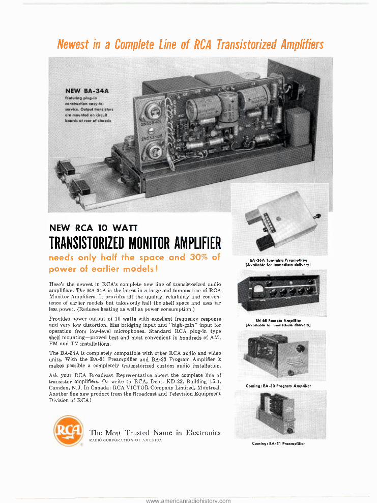
Newest in a Complete Line of RCA Transistorized Amplifiers
NEW BA -34A featuring plug -in construction easy -to- service. Output transistors are mounted on circuit boards at rear of chassis
NEW RCA 10 WATT
TRANSISTORIZED MONITOR AMPLIFIER needs only half the space and 30% of power of earlier models !
Here's the newest in RCA's complete new line of transistorized audio amplifiers. The BA-34A is the latest in a large and famous line of RCA Monitor Amplifiers. It provides all the quality, reliability and conven- ience of earlier models but takes only half the shelf space and uses far less power. (Reduces heating as well as power consumption.)
Provides power output of 10 watts with excellent frequency response and very low distortion. Has bridging input and "high- gain" input for operation from low -level microphones. Standard RCA plug -in type shelf mounting - proved best and most convenient in hundreds of AM, FM and TV installations.
The BA-34A is completely compatible with other RCA audio and video units. With the BA -31 Preamplifier and BA -33 Program Amplifier it makes possible a completely transistorized custom audio installation.
Ask your RCA Broadcast Representative about the complete line of transistor amplifiers. Or write to RCA, Dept. KD -22, Building 15 -1, Camden, N.J. In Canada: RCA VICTOR Company Limited, Montreal. Another fine new product from the Broadcast and Television Equipment Division of RCA!
The Most Trusted Name in Electronics RADIO CORPORATION or AMERICA
BA -26A Turntable Preamplifier (Available for immediate delivery)
BN -6B Remote Amplifier (Available for immediate delivery)
Coming: BA -33 Program Amplifier
Coming: BA -31 Preamplifier
www.americanradiohistory.com

To add "atmosphere" to the sales pitch... RCA Special Effects !
French chef sprite is electronically ...
fitted into a backyard scene
One of a aeries on "HOW ADVERTISERS ARE SOLD"
Form 3.14036
Products of your local sponsors can be given that "distinctive" appeal with intri- guing traveling matte effects. Using RCA Special Effects equipment, exciting slide or film backdrops can easily be inserted into commercials. You can place an animated figure into a moving background or add "atmosphere" details that give results, very simply. The system will accept signals from several sources to produce a variety of effects. In addition to traveling matte backgrounds, RCA can provide modules for 154 special effects, including wipes, split screens, block, wedge, circular and multiple frequency patterns. Any ten effects may be preselected- simply plug ten modules into the control panel. You get the right effect to add that extra sell to your pro- grams and commercials every time! Your RCA Special Effects will sell itself to advertisers and give your station a competitive edge. See your RCA Representative. Or write to RCA, Broadcast and Television Equipment, ..
Dept. JD -278, Building 15 -1, Camden, N. J. for descriptive booklet. In Canada: RCA VICTOR Company Limited, Montreal. RCA Broadcast and Television Equipment Camden, N. J.
The Most Trusted Name in Electronics RADIO CORPORATION OF AMERICA
Tmk(s) ®
RCA Special Effects Panel
Printed in U.S.A.
www.americanradiohistory.com