
tutorial_0_skwe_plate
6
Tutorial 0 - Skew Plate Contents 1 Physical introduction to the problem 2 Prerequisites 3 Objectives 3.1 Didattic objectives: 3.2 Software objectives: 4 Creating a part 4.1 Geometry 4.2 Loc al Coordinate System ( CSYS) 4.3 Property 4.4 Material 4.5 Section 4.6 Assigning material orientation 4.7 Assigning section 5 Creating the Assembly 5.1 Meshing 6 Creating the Step & Launc hing the Job 6.1 Assigning Boundary Conditions 6.2 Creating Step 6.3 Assigning Loads 6.4 Data Check and Job 7 Conclusions fig. repre sentation of t he item tha t we want to realise with this tutorial: 3D view. Physical introductio n to the problem The first tutorial shows you how to simulate a pressure job on a composite made plate. The plate is built-in at on e end, and is constrained to mov e on rails parallel to the plate axis at the other end. You will be dete rmining the midsp an deflection when the plate carries a uniform pre ssure. You will a lso as sess wh ether a linear analysis is valid for this problem . You w ill be pe rfor ming an anal ysis using Abaqus/St andard. Prerequisites No particular prerequisite is required for this tutorial #0. Anyway a bas ic knowl edge of ABAQUS may be help ful. Objectives Didattic objectiv es: comprehend the meaning of different sections and the way to chose them. to model a composite structure. Software objectives: Comprehend the conception of this software in: 1. Being able to use basic i nstrum ents of ABAQUS in order t o create a part . 2. Under standing the use of Coordinate Syst ems' usage. (Import ance in Orientation, BCs, Material definit ion, Outp ut) 3. Comprehending a stan dard str uctu re and proced ure t o realise a project in ABAQUS: Part, Material, Section, Assembly, Step , etc...
-
Upload
cen1510353 -
Category
Documents
-
view
217 -
download
0
Transcript of tutorial_0_skwe_plate
8/7/2019 tutorial_0_skwe_plate
http://slidepdf.com/reader/full/tutorial0skweplate 1/6
Tutorial 0 - Skew Plate
Contents
1 Physical introduction to the problem
2 Prerequisites
3 Objectives
3.1 Didattic objectives:
3.2 Software objectives:
4 Creating a part
4.1 Geometry
4.2 Local Coordinate System (CSYS)
4.3 Property
4.4 Material
4.5 Section
4.6 Assigning material orientation
4.7 Assigning section
5 Creating the Assembly
5.1 Meshing
6 Creating the Step & Launching the Job
6.1 Assigning Boundary Conditions
6.2 Creating Step
6.3 Assigning Loads
6.4 Data Check and Job
7 Conclusions
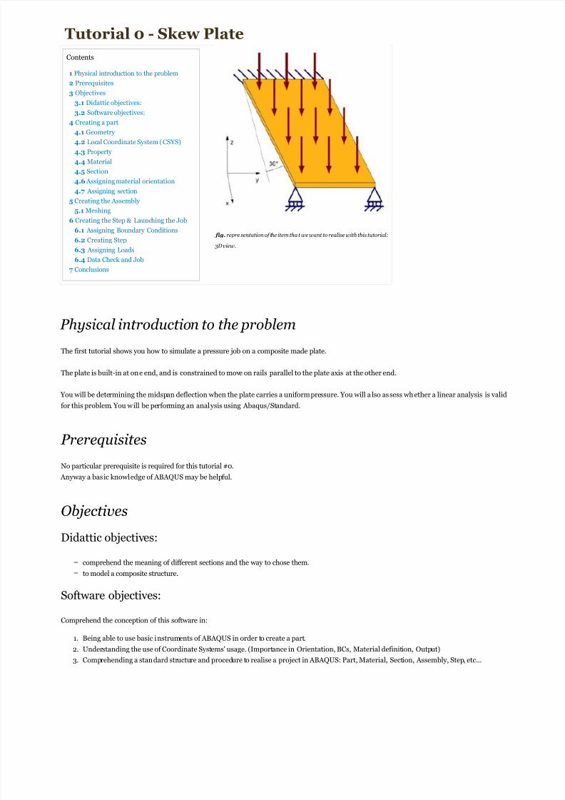
fig. repre sentation of the item tha t we want to realise with this tutorial:
3D view.
Physical introduction to the problem
The first tutorial shows you how to simulate a pressure job on a composite made plate.
The plate is built-in at one end, and is constrained to move on rails parallel to the plate axis at the other end.
You will be determining the midspan deflection when the plate carries a uniform pressure. You will a lso assess whether a linear analysis is valid
for this problem. You will be performing an analysis using Abaqus/Standard.
Prerequisites
No particular prerequisite is required for this tutorial #0.
Anyway a basic knowledge of ABAQUS may be helpful.
Objectives
Didattic objectives:
comprehend the meaning of different sections and the way to chose them.
to model a composite structure.
Software objectives:
Comprehend the conception of this software in:
1. Being able to use basic instruments of ABAQUS in order to create a part.
2. Understanding the use of Coordinate Systems' usage. (Importance in Orientation, BCs, Material definition, Output)
3. Comprehending a standard structure and procedure to realise a project in ABAQUS: Part, Material, Section, Assembly, Step, etc...

8/7/2019 tutorial_0_skwe_plate
http://slidepdf.com/reader/full/tutorial0skweplate 2/6
fig. 0.1- "Creating part" windows
fig. 0.2- multiple selection
fig. 0.3- finished sketch
Creating a part
Our plate is a parallelogram based prism. It is skewed 30° to the global
1-axis, and its thickness is 0.8 cm.
The skew plate is made of a composite material whose fibres are
oriented in a only direction, parallel to the longest segment.
This segment will be also the x-a xis of our local coordinate system,
because of the following simplicity assigning the material property and
interpreting results. As matter of fact, may be insignificant to read
results in the global system because of the angle with fibre orientation.
In this guide you will be conducted step-by-step to the part creation, in
order to let you approach easily to the software. For the next tutorials a
lot of steps will be assumed as learned by user and so will be omitted.
Geometry
Start Abaqus/CAE, double click on Parts in the main menu on the left of the page. The create part
windows (fig 0.1) will appear. Create a three-dimensional, deformable body with a planar shell base
feature. Name the part Plate, and specify an approximate part size of 4.0.
A suggested approach to creating the part geometry is outlined in the following procedure:
1. Create an arbitrary rectangle using the Create Lines: Rectangle (4 Lines) tool .
Once created a rectangle, you have to set the dimension and the desired geometry.
As you can see, there are default constraints in the created rectangle: the right angles and the
horizontal line . A deletion of these constraints to customize the geometry is in order.
2. Click on Delete tool button and select Constrains as the scope of operation in the prompt
area .
3. using Shift on your keyboard select all constraints in the figure. The selected item should become
red coloured. (fig 0.2)
4. Click Done in the prompt area to submit the operation .Now you ha ve to set new constraints: a fixed vertical edge and the couples of opposite edges as
parallel. In this way you should obtain a parallelogram in which only top and bottom edge could
rotate.
5. Click on Constraints button and the Add Constraints dialog box will appear.
Select Vertical and click on the right edge to apply the vertical constraint. Click Done in the prompt
panel.
6. Select Parallel in the Add Constraints dialog box and select both the top and bottom edge
using Shift+Click . Click Done in the prompt panel.
7. Leaving the selection on Parallel, Shift+Click on the left and right edge to select them. Click
Done in the prompt panel.
At this point you have to dimension the edges and the angle.
8. Select the Dimension tool button and then select the left edge. Click in a point at the left of
the left edge to fix the dimension and enter 0.4 in the prompt area. Click Done.
9. Select both the left and the right edges in consequence then click on a point under the
bottom line and the horizontal distance dimension will be appear. Set the horizontal distance
value to 1.0 in the prompt area and click Done.
10.Select both the lef t and the bottom edge in consequence, click on a point to fix the angle
dimension and set the value to 60° in the prompt area then click Done.
11. Click to exit the dimension editor.
At this point you should have created a model similar to the (fig. 0.3).
Now you may have finished to customize the part geometry, so click Done in the prompt area until
you will be exit by the sketch editor.

8/7/2019 tutorial_0_skwe_plate
http://slidepdf.com/reader/full/tutorial0skweplate 3/6
Importance of local CSYS
There are many advantages in using local CSYS
sometimes.
During the part creation, it should not be easy to
orientate a material in the part, because usually
you can find fibre orientation that could not be
parallel to a global axis. It should be also difficult to
orientate a load or a constraint: imagine the skew
plate considered in this tutorial, if the problem
asserts to set a condition that excludes the
displacements according to the longest edge
direction, using the global CSYS, you have to
exclude displacement on the direction y+1.73205
x, that is approximated and not so elegant. If you
set a local CSYS on the longest edge, you have only
to exclude X (local) displacement and that is all!
Another important way to comprehend the
importance of local CSYS is to compare the output
files of two works, one done with local CSYS, the
other with global CSYS. You will be noting that theresults of second work will not be
"human readable" because is insignificant to have
outputs which results are in function of Sines and
Cosines (the contributions of both the axis).
Pay attention!
Doing a sketch, it is important to make a good part quotation.
The quotes are the customized dimension and constraints of the sketch, and you have to set correct number of quotes.
Abaqus/CAE help you doing this colouring the elements of the part.
When some elements with quotes are violet, you have to delete some constraints or quote because these are too much. When these are withe coloured, it
means that is all right.
example:
fig. 0.4 - Correct q uotation fig. 0.5 - Over-qu otation fig. 0.6- Wrong q uotation
fig. 1 - Correctly quoted sketch: An horizontal edge, three right angles (it must be a parallelogram, a rectangle exactly) two edge dimensions.
fig. 2 - Over-quoted sketch: one between the three quotes/constraints in purple should be deleted.
fig. 3 - Wrong quoted sketch: the two dimension and the right angles are in contradiction because the right angle make of this part a rectangle and it is no
possible to have two opposite different edge. So you must delete a right angle or a dimension.
Local Coordinate System (CSYS)
One of the most important tools in ABAQUS/CAE is the possibility to set customized coordinates' systems.
You now will set a local CSYS according to the fibres' orientation of the composite in order
to have significant results at the end.
This orientation is parallel to our longer side of the plate, and will be the X-Axis of local
system. So the Y-Axis will stay in the plane of the surface.
1. In order to do this cl ick at long on the Create Datum CSYS button , a
selection of buttons wil l appear, select Create Datum CSYS: 2 Lines button
.
Notice that the buttons with a black triangle in the bottom
right angle, if pressed at long, will open a selection of other
related buttons.
2. The Create Datum CSYS dialog box will appear, set the name as
Customized CSYS 1 and accept Rectangular as system type.
3. As the prompt area suggest, select the line to be the X-axis, in this case select the
bottom edge, then select the right line to be in the X-Y plane.
Notice that the CSYS has been created without your
confirmation. You only have to fill out the Create Datum
CSYS dialog box that will appear to return to the part.
Property
Now you wil l create the proprieties without assigning these to the part.
Material
The plate is made of 1-layer composite material,
Create the material definition:
1. Double click on Materials in the main menu, in the Edit Material dialog box that will appear set the name toComposite

8/7/2019 tutorial_0_skwe_plate
http://slidepdf.com/reader/full/tutorial0skweplate 4/6
Material and click on Mechanical menu and Elasticity , Elastic in succession. Set the Type value to Lamina and the
values in Data module according to the following way:
Young's modulus in fibres' orientation: E 1 = 132.38 GPa
Young's modulus perpendicular to fibres' orientation: E2 = 10.756 GPa
Poisson's ratio in fibres' planes: ν12 = ν13 = 0.24
Poisson's ratio in the normal to fibres plane: ν13 = 0.49
Shear modulus in fibres' planes: G23 = 3.606 GPa
Shear modulus ratio in the normal to fibres plane: G12 = G13 = 5.6537 GPa
Notice that setting the proprieties of the material, you have to omit the units of
measurement and to convert the orders of magnitude in power of ten.
For example, instead of E1 = 132.38 GPa you have to set the E1 value as 132.28e9 that
minds 132.38 x 10⁹ or 132,380,000,000.
2. Click OK to apply changes.
Now you have created the material but it hasn't been applied to the part.
Section
In order to assign the material to the part, we can create a section.
In the section we can specify not only material settings bus a lso other proprieties of the part.
1. Double click on Sections in the main menu, in the Create Section that will appear setComposite Section as Name, Shell
as Category and Composite as Type.
2. Click Continue and the Edit Section dialog box will appear.
3. Set Before A nalysis Section Integration and in the Basic tab click on the second row with the right button of mouse and
select Delete Rows because in this part you will consider a single layer composite section.
4. Set the "Composite Material" that you created as Material of the layer, 0.008 as Thickness value (see the quotes in the main
figure at the top), 0 as Orientation Angle (because you will s pecify after the section orientation) and Level 1 as Ply Name.
5. Click OK .
Now you have created the section but it hasn't been applied to the part.
Assigning material orientation
1. Click on Assign in the menu bar of ABAQUS and select Material Orientation.
2. As the prompt area suggests, cl ick on a point in the centre of the part to select the area, then click Done.IMPORTANT! During this step you will assign the orientation to the material (that is not isotropic material!)
3. In the prompt area click on Datum CSYS List... and select the created CSYS named Customized CSYS 1.
4. Click OK and then accept the custom defaults in the the dialog box that wil l appear.
Assigning section
1. Click on Assign in the menu bar of ABAQUS and select Section.
2. As the prompt area suggests, cl ick on a point in the centre of the part to select the area, then click Done.
3. Click OK to accept the default settings and assign the created section to the part.
Creating the Assembly
1. Click on the "+" near Assembly to expand the assembly menu in the main menu.
2. Double click on Instance and the Create Instance dialog box will appear.
3. Set Independent as Instance Type ans click OK to apply and exit.
By default the software will create a supplementary CSYS similar to the Global one. If you expand the Features menu in main menu
you will find the created CSYS. You can click with the right button of the mouse and delete it.
Meshing

8/7/2019 tutorial_0_skwe_plate
http://slidepdf.com/reader/full/tutorial0skweplate 5/6
Before meshing the part, it's important to impose some rules to obtain a good mesh. This will be the definition of size and shape of the
elements as well as mesh pattern.
1. Select Mesh from the Module menu that you can find just up the part view.
2. In the menu bar of Abaqus will appear the Seeds menu. Here select Instance and accept the default settings in the Global
Seeds dialog box that will appear.
Notice that if you can not find Instance in the Seeds menu, probably Part is selected
in the Object form just up the part view. Select Assembly and try again.
3. Click Done in the prompt area to apply the seeding.
Now proceed in meshing the part.
4. In Mesh menu in menu bar, select Instance and click Yes in the prompt area to mesh the part. The part will become cyan
coloured.
Notice that in order to view the mesh, select the Render Model: Wireframebutton
in the main bar. You should also have been selected the Show Native Mesh button
.
Creating the Step & Launching the Job
Why to create a step before assigning boundary conditions and loads?
Because the simulation is made of multiple steps. In this case the load application to the plate is only a step of your job. You can find in future
more steps with different loads as subsequence of the job.
The initial step contains the boundary conditions, a pplied before starting the job.
You have now to create the boundary conditions both on the left and the right edges of the plate and apply the pressure load.
Assigning Boundary Conditions
1. In the model three double click on BCs, set the name as Fix Left Side and select Mechanical Displacement/Rotation in the
Create Boundary Condition dialg box will appear.
2. Click Contine.. and select the left edge in the part view then click Done in the prompt area.
3. In the Edit Boundary Contidion dialog box that will appear click Edit to customize the CSYS and select the created Customized
CSYS 1.
4. Select all the possible displacement to fix the left side of the plate and click OK .
5. In the model three double click on BCs, set the name as Fix Right Side and select Mechanical Displacement/Rotation in
the Create Boundary Conditiondialg box will appear.
6. Click Contine.. and select the right edge in the part view then click Done in the prompt area.
7. In the Edit Boundary Contidion dialog box that will appear click Edit to customize the CSYS and select the created Customized
CSYS 1.
8. Select all the possible displacement but not U1 and click OK .
Creating Step
1. In the model three double click on Steps, set the name as Apply Pressure and accept the Static, General procedure type then
click Continue..
2. Click OK accepting the default settings.
Assigning Loads
1. In the model three double click on Load, set the name as Pressure and select Mechanical Pressure in the Create Load dialg
box that will appear.
2. Select Apply Pressure as Step and click Continue..
3. Click in the centre of the part to select the surface for the load and click Done in the prompt area.
4. Select Brown in the prompt area to apply the load on the top surface of the plate.
5. In the Edit Load dialog box that will appear select Uniform as Distribution an set20000 as Magnitude (It is the value of the
presure: 20 KPa).
6. Click OK .

8/7/2019 tutorial_0_skwe_plate
http://slidepdf.com/reader/full/tutorial0skweplate 6/6
Data Check and Job
1. In the model three double click on Jobs and click Continue..
2. Select OK to accept the default settings.
3. Expand the Jobs menu in the model three and click on Job-1 with the right mouse button to select Data Check .
4. If Data Checks report no error in the prompt area, you can select Submit from the right button menu of Job-1 and wait the output
Submitted Successful in the prompt area.
Conclusions
Once terminated the job you can see the results of analysis by clicking on Results in the right button menu of Job-1.
The results view will appear. Here you can see the deformation and stress coloured entity by playing with view buttons.
For any question or suggestion, contact [email protected]. Thank you.


