Tutorial SIMARIS Design 8 En
114
SIMARIS design T utorial SIMARIS design Software for efficient dimensioning of power distribution systems 1 Introduction 2 Getting Started 3 Network Design 4 Dimensioning 5 Project Output 6 More about SIMARIS
-
Upload
kalyanmalla -
Category
Documents
-
view
239 -
download
0
Transcript of Tutorial SIMARIS Design 8 En

8/19/2019 Tutorial SIMARIS Design 8 En
http://slidepdf.com/reader/full/tutorial-simaris-design-8-en 1/114
SIMARIS design Tutorial
SIMARIS design
Software for efficient dimensioningof power distribution systems
1 Introduction
2 Getting Started
3 Network Design
4 Dimensioning
5 Project Output
6 More about SIMARIS
8/19/2019 Tutorial SIMARIS Design 8 En
http://slidepdf.com/reader/full/tutorial-simaris-design-8-en 2/114
Page 2
Software for efficient dimensioningof power distribution systems
SIMARIS design
SIMARIS design Tutorial
1 Introduction
2 Getting Started
3 Network Design
4 Dimensioning
5 Project Output
6 More about SIMARIS
1 2 3 4 5 6Start
SIMARIS planning tools
SIMARIS design
Additional functions in SIMARIS design professional
1 Introduction

8/19/2019 Tutorial SIMARIS Design 8 En
http://slidepdf.com/reader/full/tutorial-simaris-design-8-en 3/114
Restricted © Siemens AG 2014 All rights reserved.
March 2014Page 3 SIMARIS design1 2 3 4 5 6Start
SIMARIS planning tools
The SIMARIS planning tools provide efficient support for dimensioning an electric power distribution
system and determining the equipment and distribution boards for it.
• SIMARIS design for network calculation and dimensioning
• SIMARIS project for determining the space requirements of distribution boards and the budget,
and for generating specifications (bills of quantities)
• SIMARIS curves to display tripping characteristics, as well as cut-off current characteristics
and let-through energy curves
The advantages of SIMARIS planning tools:
• Intuitive and easy handling with user-friendly documentation options for the planning results
• End-to-end planning for all devices and systems from the medium-voltage level to the power
consumer
• Automatic selection of matching components and distribution board systems
• High degree of planning reliability plus flexibility in the planning and implementation process
1. Introduction

8/19/2019 Tutorial SIMARIS Design 8 En
http://slidepdf.com/reader/full/tutorial-simaris-design-8-en 4/114
Restricted © Siemens AG 2014 All rights reserved.
March 2014Page 4 SIMARIS design1 2 3 4 5 6Start
SIMARIS design
SIMARIS design enables electric networks to be dimensioned which are based on real products ranging
from the medium-voltage down to the load level including automatic selection of suitable equipment.
• Busbar trunking systems for power transmission and distribution can also be integrated in your
planning.
• The equipment is dimensioned according to the accepted rules of good installation practice and all
applicable standards (VDE, IEC).
• Network operating modes and switching conditions can be defined as desired.
• Parallel cables in feed-in circuits can be separately protected.
• Functional endurance, if required, can be factored into the calculation.
• It is possible to consider lightning and surge protection, if required.
• As a result, you will receive a calculation of the short-circuit, load flow, voltage drop, and an energy
report which takes into account the necessary protection against personal injury, short-circuit and
overload.
• To document results, a wide variety of output options is provided.
• One useful output variant is the export file of your project for further processing in SIMARIS project.
This facilitates determining the space requirements for the distribution boards and makes it easy for
you to create a basis for budget finding.
1. Introduction
8/19/2019 Tutorial SIMARIS Design 8 En
http://slidepdf.com/reader/full/tutorial-simaris-design-8-en 5/114
Restricted © Siemens AG 2014 All rights reserved.
March 2014Page 5 SIMARIS design1 2 3 4 5 6Start
Additional functions in SIMARIS design professional
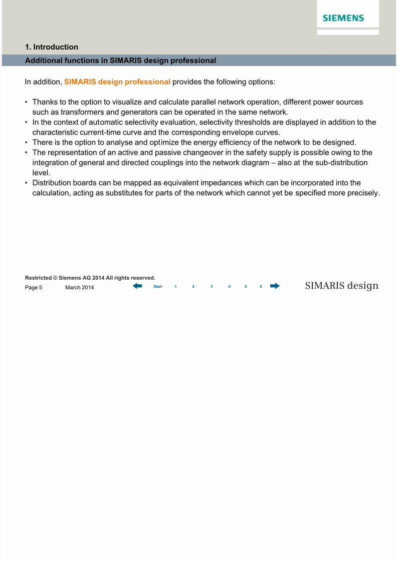
In addition, SIMARIS design professional provides the following options:
• Thanks to the option to visualize and calculate parallel network operation, different power sources
such as transformers and generators can be operated in the same network.
• In the context of automatic selectivity evaluation, selectivity thresholds are displayed in addition to the
characteristic current-time curve and the corresponding envelope curves.
• There is the option to analyse and optimize the energy efficiency of the network to be designed.
• The representation of an active and passive changeover in the safety supply is possible owing to the
integration of general and directed couplings into the network diagram – also at the sub-distribution
level.
• Distribution boards can be mapped as equivalent impedances which can be incorporated into the
calculation, acting as substitutes for parts of the network which cannot yet be specified more precisely.
1. Introduction

8/19/2019 Tutorial SIMARIS Design 8 En
http://slidepdf.com/reader/full/tutorial-simaris-design-8-en 6/114
Page 6
Software for efficient dimensioningof power distribution systems
SIMARIS design
SIMARIS design Tutorial
1 Introduction
2 Getting Started
3 Network Design
4 Dimensioning
5 Project Output
6 More about SIMARIS
1 2 3 4 5 6Start
2 Getting Started
Project definition
Introduction to network design
8/19/2019 Tutorial SIMARIS Design 8 En
http://slidepdf.com/reader/full/tutorial-simaris-design-8-en 7/114
Restricted © Siemens AG 2014 All rights reserved.
March 2014Page 7 SIMARIS design1 2 3 4 5 6Start
Project definition
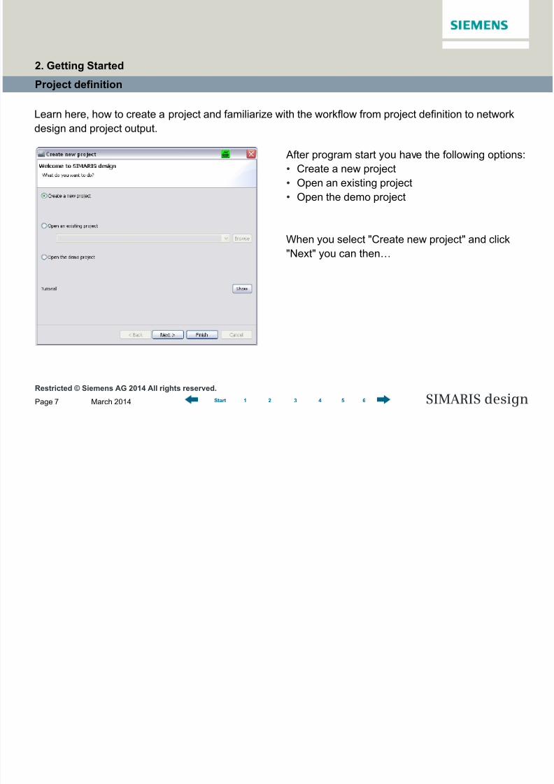
Learn here, how to create a project and familiarize with the workflow from project definition to network
design and project output.
After program start you have the following options:
• Create a new project
• Open an existing project
• Open the demo project
When you select "Create new project" and click
"Next" you can then…
2. Getting Started

8/19/2019 Tutorial SIMARIS Design 8 En
http://slidepdf.com/reader/full/tutorial-simaris-design-8-en 8/114
Restricted © Siemens AG 2014 All rights reserved.
March 2014Page 8 SIMARIS design1 2 3 4 5 6Start
Project definition
… enter master data for the project …
2. Getting Started
8/19/2019 Tutorial SIMARIS Design 8 En
http://slidepdf.com/reader/full/tutorial-simaris-design-8-en 9/114
Restricted © Siemens AG 2014 All rights reserved.
March 2014Page 9 SIMARIS design1 2 3 4 5 6Start
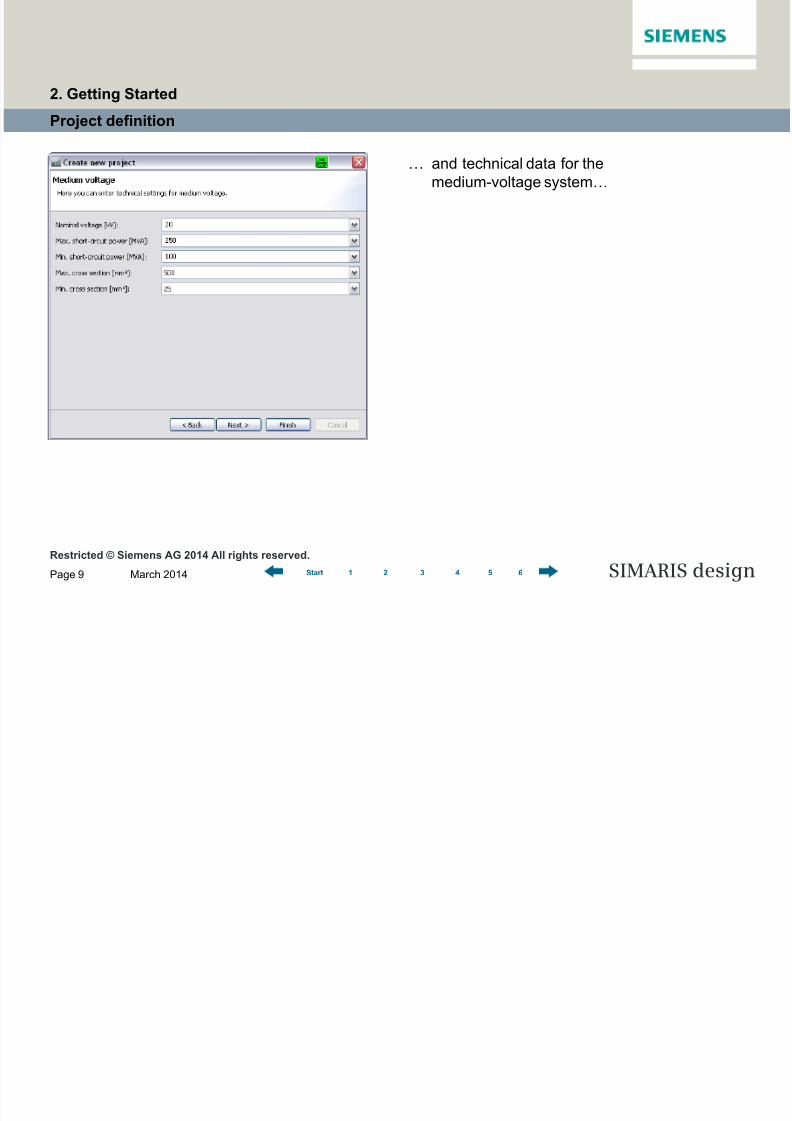
Project definition
… and technical data for the
medium-voltage system…
2. Getting Started
8/19/2019 Tutorial SIMARIS Design 8 En
http://slidepdf.com/reader/full/tutorial-simaris-design-8-en 10/114
Restricted © Siemens AG 2014 All rights reserved.
March 2014Page 10 SIMARIS design1 2 3 4 5 6Start
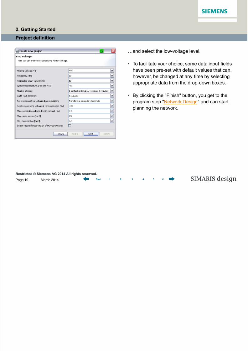
Project definition
…and select the low-voltage level.
• To facilitate your choice, some data input fields
have been pre-set with default values that can,
however, be changed at any time by selecting
appropriate data from the drop-down boxes.
• By clicking the "Finish" button, you get to the
program step "Network Design" and can start
planning the network.
2. Getting Started

8/19/2019 Tutorial SIMARIS Design 8 En
http://slidepdf.com/reader/full/tutorial-simaris-design-8-en 11/114
Restricted © Siemens AG 2014 All rights reserved.
March 2014Page 11 SIMARIS design1 2 3 4 5 6Start
Project definition
Clicking the program steps on the
navigation bar allows you to go to another
step at any time you choose, while you are
editing a project.
2. Getting Started
8/19/2019 Tutorial SIMARIS Design 8 En
http://slidepdf.com/reader/full/tutorial-simaris-design-8-en 12/114
Restricted © Siemens AG 2014 All rights reserved.
March 2014Page 12 SIMARIS design1 2 3 4 5 6Start
Project definition
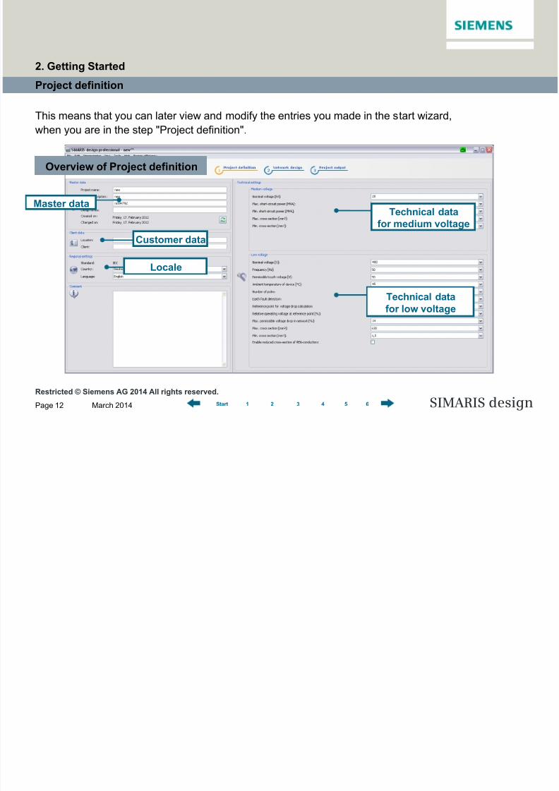
This means that you can later view and modify the entries you made in the start wizard,
when you are in the step "Project definition".
Overview of Project definition
Master data
Customer data
Locale
Technical data
for medium voltage
Technical datafor low voltage
2. Getting Started

8/19/2019 Tutorial SIMARIS Design 8 En
http://slidepdf.com/reader/full/tutorial-simaris-design-8-en 13/114
Restricted © Siemens AG 2014 All rights reserved.
March 2014Page 13 SIMARIS design1 2 3 4 5 6Start
Project definition
In this context, please note that the edited network must be redimensioned after
every change in the technical settings.
In addition, you can "localise" the Regional settings made in the Project definition
step, i.e. choose the country-specific product portfolio relevant for your planning by
selecting a country and a language matching this country, or English as the project
language.
All settings defined in this step – this includes both technical data and country andlanguage settings – will be automatically saved for future projects, but can be
changed again if necessary, which greatly facilitates working and collaborating at
international projects.
2. Getting Started

8/19/2019 Tutorial SIMARIS Design 8 En
http://slidepdf.com/reader/full/tutorial-simaris-design-8-en 14/114
Restricted © Siemens AG 2014 All rights reserved.
March 2014Page 14 SIMARIS design1 2 3 4 5 6Start
Introduction to network design
Graphics window
Library, favourites
graphic/symbols
Tool bar
Hints
Properties circuit
Properties of equipment
Network Design – Overview
2. Getting Started

8/19/2019 Tutorial SIMARIS Design 8 En
http://slidepdf.com/reader/full/tutorial-simaris-design-8-en 15/114
Restricted © Siemens AG 2014 All rights reserved.
March 2014Page 15 SIMARIS design1 2 3 4 5 6Start
Introduction to network design
The Library (top left) provides all elements
required for creating a network diagram. You can
either rely on Favourites, or integrate symbols into
the network diagram.
In the "Network design" step, there are the following sections:
The network diagram is built up in the graphics
window (on the right of the screen display) from
Library elements and/or Favourites.
2. Getting Started

8/19/2019 Tutorial SIMARIS Design 8 En
http://slidepdf.com/reader/full/tutorial-simaris-design-8-en 16/114
Restricted © Siemens AG 2014 All rights reserved.
March 2014Page 16 SIMARIS design1 2 3 4 5 6Start
Introduction to network design
Hints and tips how to edit the network, and the
Properties of the elements marked on thegraphics, i.e. circuits and equipment, can be found
below the Library on the left.
Thus you can easily and quickly view the most
important information about the network diagram
elements you are editing.
The tool bar above the graphics window contains
all important functions for editing the network
diagram.
…
…
2. Getting Started
8/19/2019 Tutorial SIMARIS Design 8 En
http://slidepdf.com/reader/full/tutorial-simaris-design-8-en 17/114
Restricted © Siemens AG 2014 All rights reserved.
March 2014Page 17 SIMARIS design1 2 3 4 5 6Start
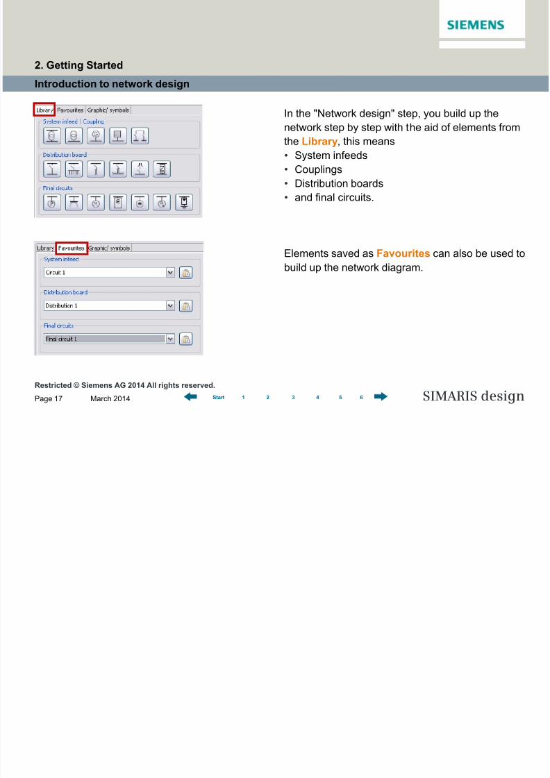
Introduction to network design
In the "Network design" step, you build up the
network step by step with the aid of elements from
the Library, this means
• System infeeds
• Couplings
• Distribution boards
• and final circuits.
Elements saved as Favourites can also be used to
build up the network diagram.
2. Getting Started

8/19/2019 Tutorial SIMARIS Design 8 En
http://slidepdf.com/reader/full/tutorial-simaris-design-8-en 18/114
Restricted © Siemens AG 2014 All rights reserved.
March 2014Page 18 SIMARIS design1 2 3 4 5 6Start
Introduction to network design
It is also possible to add graphic elements,
symbols and annotations to structure the network
diagram and add suitable captions and labels.
Various editing options for the network diagram,
which can be called up
• using the tool bar,
• the menu,• and sometimes the context menu
(right mouse click) as well,
support you in creating and editing a
network diagram.
…
…
Tool bar
2. Getting Started

8/19/2019 Tutorial SIMARIS Design 8 En
http://slidepdf.com/reader/full/tutorial-simaris-design-8-en 19/114
Restricted © Siemens AG 2014 All rights reserved.
March 2014Page 19 SIMARIS design1 2 3 4 5 6Start
Introduction to network design
Please also refer to the sections "How to create network elements" and "Working in
the network diagram" in “Network Design”.
In the "Network Design" step, the components shown on the network diagram are
automatically or manually dimensioned. More about this in "Dimensioning".
2. Getting Started
8/19/2019 Tutorial SIMARIS Design 8 En
http://slidepdf.com/reader/full/tutorial-simaris-design-8-en 20/114
Page 20
Software for efficient dimensioningof power distribution systems
SIMARIS design
SIMARIS design Tutorial
1 Introduction
2 Getting Started
3 Network Design
4 Dimensioning
5 Project Output
6 More about SIMARIS
1 2 3 4 5 6Start
Working in the network diagram
> Properties
> Moving and aligning network elements
> Copying and pasting
> Favourites
How to create network elements
> System infeeds
> Distribution board
> Loads> Separate networks
> Busbar systems and loads
> Annotations and graphic elements
> Search options
Couplings
> General couplings
> Unidirectional couplings
> Unidirectional coupling at the sub-distribution board level
3 Network Design
8/19/2019 Tutorial SIMARIS Design 8 En
http://slidepdf.com/reader/full/tutorial-simaris-design-8-en 21/114
Restricted © Siemens AG 2014 All rights reserved.
March 2014Page 21 SIMARIS design1 2 3 4 5 6Start
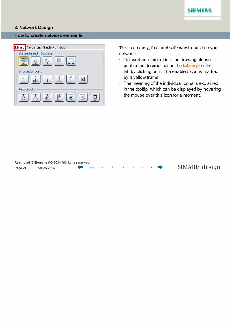
How to create network elements
This is an easy, fast, and safe way to build up your
network:
• To insert an element into the drawing please
enable the desired icon in the Library on the
left by clicking on it. The enabled icon is marked
by a yellow frame.
• The meaning of the individual icons is explained
in the tooltip, which can be displayed by hovering
the mouse over this icon for a moment.
3. Network Design
8/19/2019 Tutorial SIMARIS Design 8 En
http://slidepdf.com/reader/full/tutorial-simaris-design-8-en 22/114
Restricted © Siemens AG 2014 All rights reserved.
March 2014Page 22 SIMARIS design1 2 3 4 5 6Start
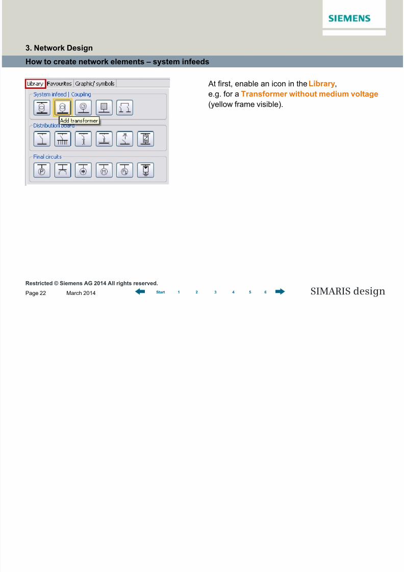
How to create network elements – system infeeds
At first, enable an icon in the Library,
e.g. for a Transformer without medium voltage
(yellow frame visible).
3. Network Design

8/19/2019 Tutorial SIMARIS Design 8 En
http://slidepdf.com/reader/full/tutorial-simaris-design-8-en 23/114
Restricted © Siemens AG 2014 All rights reserved.
March 2014Page 23 SIMARIS design1 2 3 4 5 6Start
How to create network elements – system infeeds
Then you can click on the first element, which
should always be an infeed, to place it on the
network diagram, which means that you now
create it.
• Provided that you have set automatic
consideration of lightning and surge protection, a
screen will be opened where you can make your
selections.
After clicking "Finish", you will see another
dialog where you can specify parameters for
the new element.
3. Network Design

8/19/2019 Tutorial SIMARIS Design 8 En
http://slidepdf.com/reader/full/tutorial-simaris-design-8-en 24/114
Restricted © Siemens AG 2014 All rights reserved.
March 2014Page 24 SIMARIS design1 2 3 4 5 6Start
How to create network elements – system infeeds
Result shown in the network diagram, when a
transformer (without medium voltage) is created:
3. Network Design
8/19/2019 Tutorial SIMARIS Design 8 En
http://slidepdf.com/reader/full/tutorial-simaris-design-8-en 25/114
Restricted © Siemens AG 2014 All rights reserved.
March 2014Page 25 SIMARIS design1 2 3 4 5 6Start
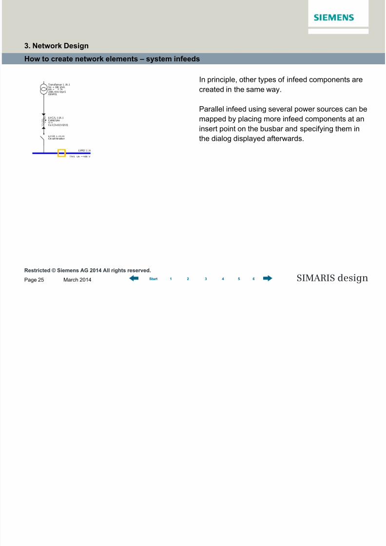
How to create network elements – system infeeds
In principle, other types of infeed components are
created in the same way.
Parallel infeed using several power sources can be
mapped by placing more infeed components at an
insert point on the busbar and specifying them in
the dialog displayed afterwards.
3. Network Design

8/19/2019 Tutorial SIMARIS Design 8 En
http://slidepdf.com/reader/full/tutorial-simaris-design-8-en 26/114
Restricted © Siemens AG 2014 All rights reserved.
March 2014Page 26 SIMARIS design1 2 3 4 5 6Start
How to create network elements – system infeeds
The result for linking infeed components is
shown here.
A detailed description on how to create couplings
can be found in the "Couplings" section.
3. Network Design

8/19/2019 Tutorial SIMARIS Design 8 En
http://slidepdf.com/reader/full/tutorial-simaris-design-8-en 27/114
Restricted © Siemens AG 2014 All rights reserved.
March 2014Page 27 SIMARIS design1 2 3 4 5 6Start
How to create network elements – distribution boards
Distribution boards are created in the same way:
At first enable an icon in the Library,
e.g. for a sub-distribution board (yellow frame
visible).
3. Network Design

8/19/2019 Tutorial SIMARIS Design 8 En
http://slidepdf.com/reader/full/tutorial-simaris-design-8-en 28/114
Restricted © Siemens AG 2014 All rights reserved.
March 2014Page 28 SIMARIS design1 2 3 4 5 6Start
How to create network elements – distribution boards
• Possible insert points in the network diagram are
marked by a yellow rectangle, when hovering the
mouse over it.
• You can find insert points on the graphs
representing distribution boards (blue lines)
and the busbar trunking systems (green lines).
• To add elements, left-click such an insert point,
keep the mouse key pressed and drag the
mouse away from the insert point at a right angle
to the blue or green line.
• After you release the mouse button, another
dialog is automatically displayed, where you can
specify parameters of the element that was just
placed.
3. Network Design

8/19/2019 Tutorial SIMARIS Design 8 En
http://slidepdf.com/reader/full/tutorial-simaris-design-8-en 29/114
Restricted © Siemens AG 2014 All rights reserved.
March 2014Page 29 SIMARIS design1 2 3 4 5 6Start
How to create network elements – distribution boards
Depending on the selected setting regarding
lightning and overvoltage protection, more
information is required.
3. Network Design

8/19/2019 Tutorial SIMARIS Design 8 En
http://slidepdf.com/reader/full/tutorial-simaris-design-8-en 30/114
Restricted © Siemens AG 2014 All rights reserved.
March 2014Page 30 SIMARIS design1 2 3 4 5 6Start
How to create network elements – distribution boards
Result in the network diagram In principle, other distribution boards are created in
the same way. A detailed description on how to add
busbar trunking systems can be found in the
"Busbar systems and loads" section.
3. Network Design
8/19/2019 Tutorial SIMARIS Design 8 En
http://slidepdf.com/reader/full/tutorial-simaris-design-8-en 31/114
Restricted © Siemens AG 2014 All rights reserved.
March 2014Page 31 SIMARIS design1 2 3 4 5 6Start
How to create network elements – loads
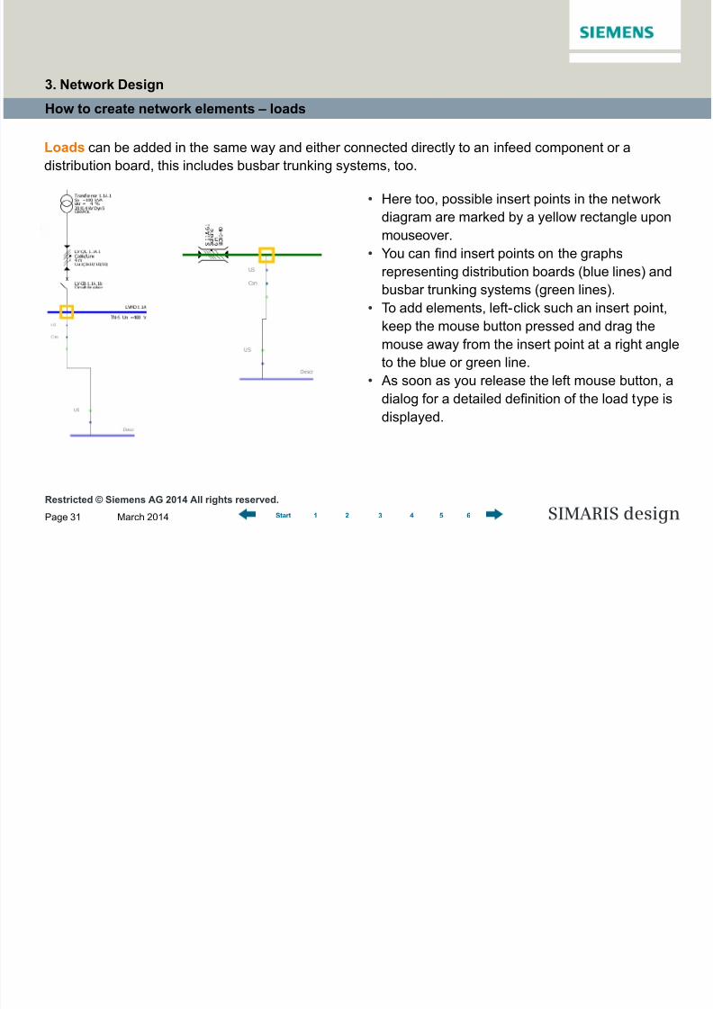
Loads can be added in the same way and either connected directly to an infeed component or a
distribution board, this includes busbar trunking systems, too.
• Here too, possible insert points in the network
diagram are marked by a yellow rectangle upon
mouseover.
• You can find insert points on the graphsrepresenting distribution boards (blue lines) and
busbar trunking systems (green lines).
• To add elements, left-click such an insert point,
keep the mouse button pressed and drag the
mouse away from the insert point at a right angle
to the blue or green line.
• As soon as you release the left mouse button, adialog for a detailed definition of the load type is
displayed.
3. Network Design

8/19/2019 Tutorial SIMARIS Design 8 En
http://slidepdf.com/reader/full/tutorial-simaris-design-8-en 32/114
Restricted © Siemens AG 2014 All rights reserved.
March 2014Page 32 SIMARIS design1 2 3 4 5 6Start
How to create network elements – loads
To add a stationary load, you must at first enable
the corresponding icon in the Library again.
3. Network Design

8/19/2019 Tutorial SIMARIS Design 8 En
http://slidepdf.com/reader/full/tutorial-simaris-design-8-en 33/114
Restricted © Siemens AG 2014 All rights reserved.March 2014Page 33 SIMARIS design1 2 3 4 5 6Start
How to create network elements – loads
When the element is placed at a suitable insert
point on the network diagram, a dialog for
specifying technical data for connecting the load
circuit is displayed.
3. Network Design
8/19/2019 Tutorial SIMARIS Design 8 En
http://slidepdf.com/reader/full/tutorial-simaris-design-8-en 34/114
Restricted © Siemens AG 2014 All rights reserved.March 2014Page 34 SIMARIS design1 2 3 4 5 6Start
How to create network elements – loads
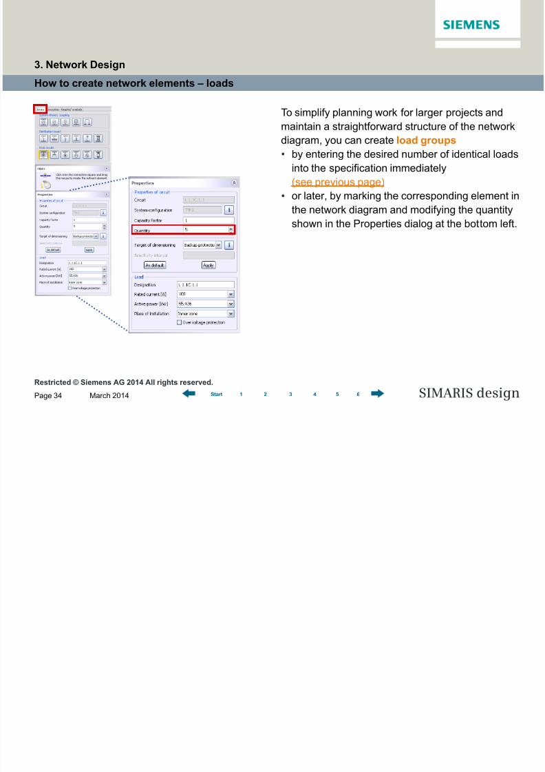
To simplify planning work for larger projects and
maintain a straightforward structure of the network
diagram, you can create load groups
• by entering the desired number of identical loads
into the specification immediately
(see previous page)
• or later, by marking the corresponding element inthe network diagram and modifying the quantity
shown in the Properties dialog at the bottom left.
3. Network Design
8/19/2019 Tutorial SIMARIS Design 8 En
http://slidepdf.com/reader/full/tutorial-simaris-design-8-en 35/114
Restricted © Siemens AG 2014 All rights reserved.March 2014Page 35 SIMARIS design1 2 3 4 5 6Start
How to create network elements – loads
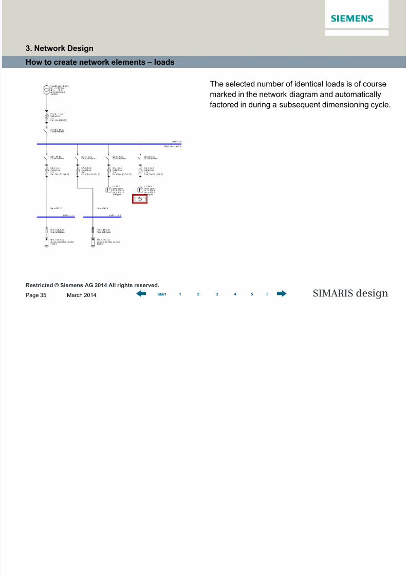
The selected number of identical loads is of course
marked in the network diagram and automatically
factored in during a subsequent dimensioning cycle.
3. Network Design

8/19/2019 Tutorial SIMARIS Design 8 En
http://slidepdf.com/reader/full/tutorial-simaris-design-8-en 36/114
Restricted © Siemens AG 2014 All rights reserved.March 2014Page 36 SIMARIS design1 2 3 4 5 6Start
How to create network elements – loads
If the data for the load circuits to be planned is not
known in detail, you can still create them on the
network diagram as cumulated or dummy loads.
3. Network Design
8/19/2019 Tutorial SIMARIS Design 8 En
http://slidepdf.com/reader/full/tutorial-simaris-design-8-en 37/114
Restricted © Siemens AG 2014 All rights reserved.March 2014Page 37 SIMARIS design1 2 3 4 5 6Start
How to create network elements – loads
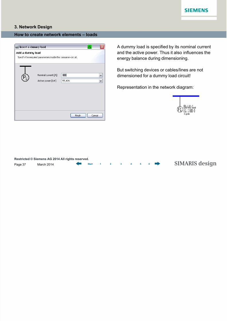
A dummy load is specified by its nominal current
and the active power. Thus it also influences the
energy balance during dimensioning.
But switching devices or cables/lines are not
dimensioned for a dummy load circuit!
Representation in the network diagram:
3. Network Design

8/19/2019 Tutorial SIMARIS Design 8 En
http://slidepdf.com/reader/full/tutorial-simaris-design-8-en 38/114
Restricted © Siemens AG 2014 All rights reserved.March 2014Page 38 SIMARIS design1 2 3 4 5 6Start
How to create network elements – loads
The “Motor” icon allows a motor or a motor group
(several identical motors) to be connected to a
main or sub-distribution board.
3. Network Design

8/19/2019 Tutorial SIMARIS Design 8 En
http://slidepdf.com/reader/full/tutorial-simaris-design-8-en 39/114
Restricted © Siemens AG 2014 All rights reserved.March 2014Page 39 SIMARIS design1 2 3 4 5 6Start
How to create network elements – loads
Besides mapping simple standard motor
protection, you can also select and dimension
motor starter combinations which are protected
by circuit-breakers or fuses.
3. Network Design

8/19/2019 Tutorial SIMARIS Design 8 En
http://slidepdf.com/reader/full/tutorial-simaris-design-8-en 40/114
Restricted © Siemens AG 2014 All rights reserved.March 2014Page 40 SIMARIS design1 2 3 4 5 6Start
How to create network elements – loads
If "Motor starter combination" was selected, the
next dialog (Starting mode) allows to choose
between
• Direct-on-line starter
• Starter for reversing mode
• Star-delta starter
• Soft starter.
Representation of a star-delta starter on the
network diagram:
3. Network Design
8/19/2019 Tutorial SIMARIS Design 8 En
http://slidepdf.com/reader/full/tutorial-simaris-design-8-en 41/114
Restricted © Siemens AG 2014 All rights reserved.March 2014Page 41 SIMARIS design1 2 3 4 5 6Start
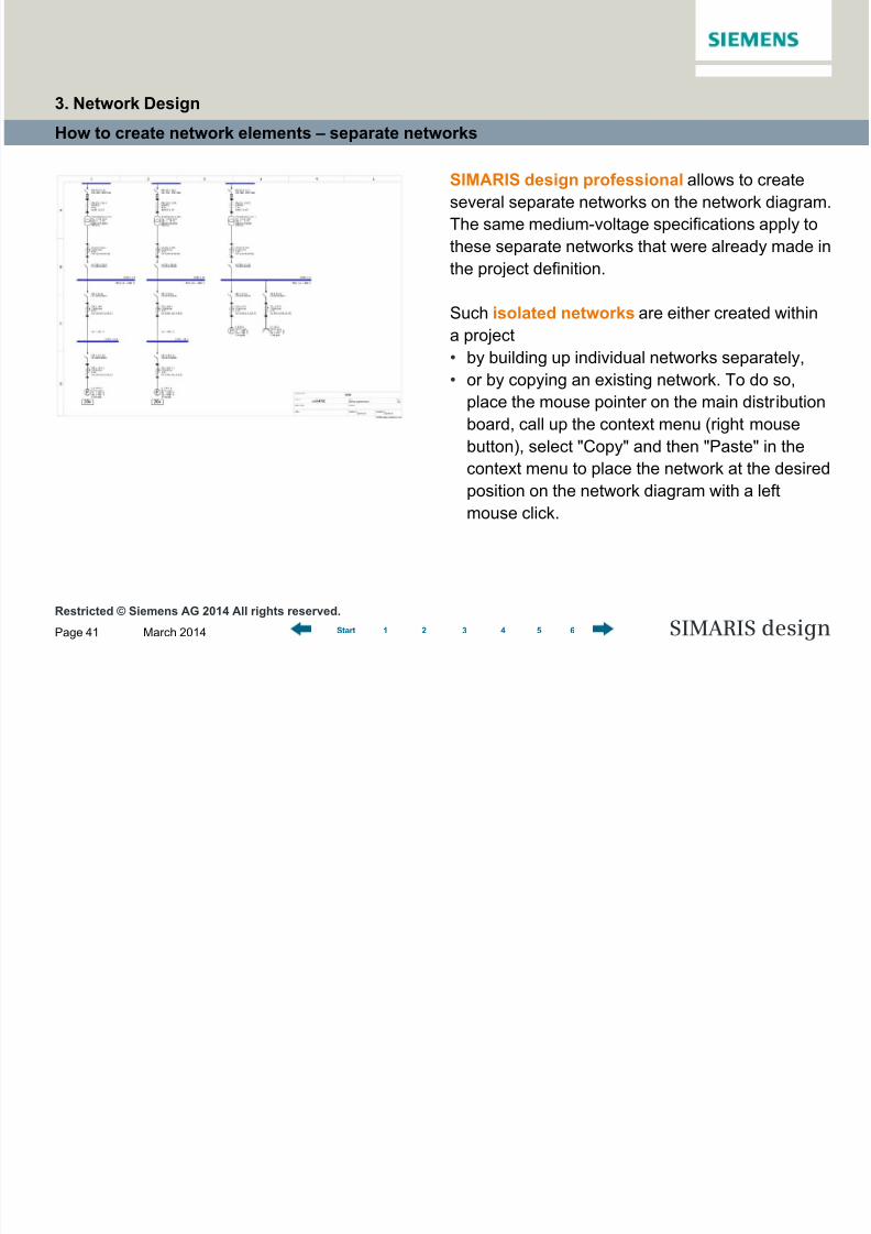
How to create network elements – separate networks
SIMARIS design professional allows to create
several separate networks on the network diagram.
The same medium-voltage specifications apply to
these separate networks that were already made in
the project definition.
Such isolated networks are either created withina project
• by building up individual networks separately,
• or by copying an existing network. To do so,
place the mouse pointer on the main distribution
board, call up the context menu (right mouse
button), select "Copy" and then "Paste" in the
context menu to place the network at the desired
position on the network diagram with a left
mouse click.
3. Network Design

8/19/2019 Tutorial SIMARIS Design 8 En
http://slidepdf.com/reader/full/tutorial-simaris-design-8-en 42/114
Restricted © Siemens AG 2014 All rights reserved.March 2014Page 42 SIMARIS design1 2 3 4 5 6Start
How to create network elements – busbar systems and loads
SIMARIS design also helps you integrate busbar systems for power transmission and distribution into
your planning concept and displays them on the network diagram.
First, enable the "Busbar trunking system" icon in the Library,
• place the system at a suitable connection/insert point,
• specify the data that is still missing
and select the matchingbusbar system.
3. Network Design
8/19/2019 Tutorial SIMARIS Design 8 En
http://slidepdf.com/reader/full/tutorial-simaris-design-8-en 43/114
Restricted © Siemens AG 2014 All rights reserved.March 2014Page 43 SIMARIS design1 2 3 4 5 6Start
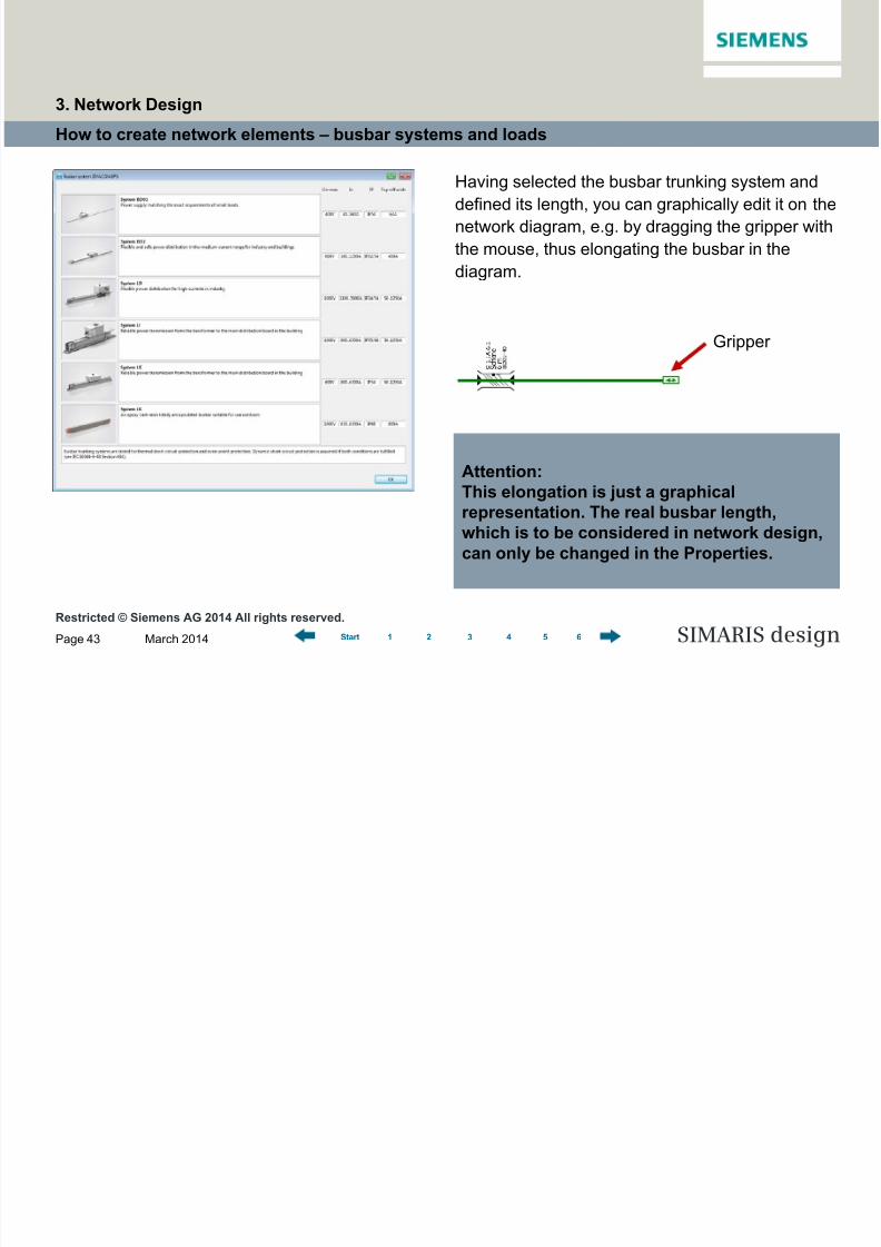
How to create network elements – busbar systems and loads
Having selected the busbar trunking system and
defined its length, you can graphically edit it on the
network diagram, e.g. by dragging the gripper with
the mouse, thus elongating the busbar in the
diagram.
Gripper
Attention:This elongation is just a graphical
representation. The real busbar length,
which is to be considered in network design,
can only be changed in the Properties.
3. Network Design

8/19/2019 Tutorial SIMARIS Design 8 En
http://slidepdf.com/reader/full/tutorial-simaris-design-8-en 44/114
Restricted © Siemens AG 2014 All rights reserved.March 2014Page 44 SIMARIS design1 2 3 4 5 6Start
How to create network elements – busbar systems and loads
More busbar properties, such as degree of
protection and mounting type, can be modified at
any time.
To do so, position the mouse pointer on the item of
equipment to be edited, e.g. the busbar, so that
• you can either change the equipment propertiesdirectly which are displayed on screen to the
bottom left of the network diagram,
• or call up detailed properties using the context
menu (right-click) and make the desired changes
in the dialog now displayed according to project
requirements.
3. Network Design
8/19/2019 Tutorial SIMARIS Design 8 En
http://slidepdf.com/reader/full/tutorial-simaris-design-8-en 45/114
Restricted © Siemens AG 2014 All rights reserved.March 2014Page 45 SIMARIS design1 2 3 4 5 6Start
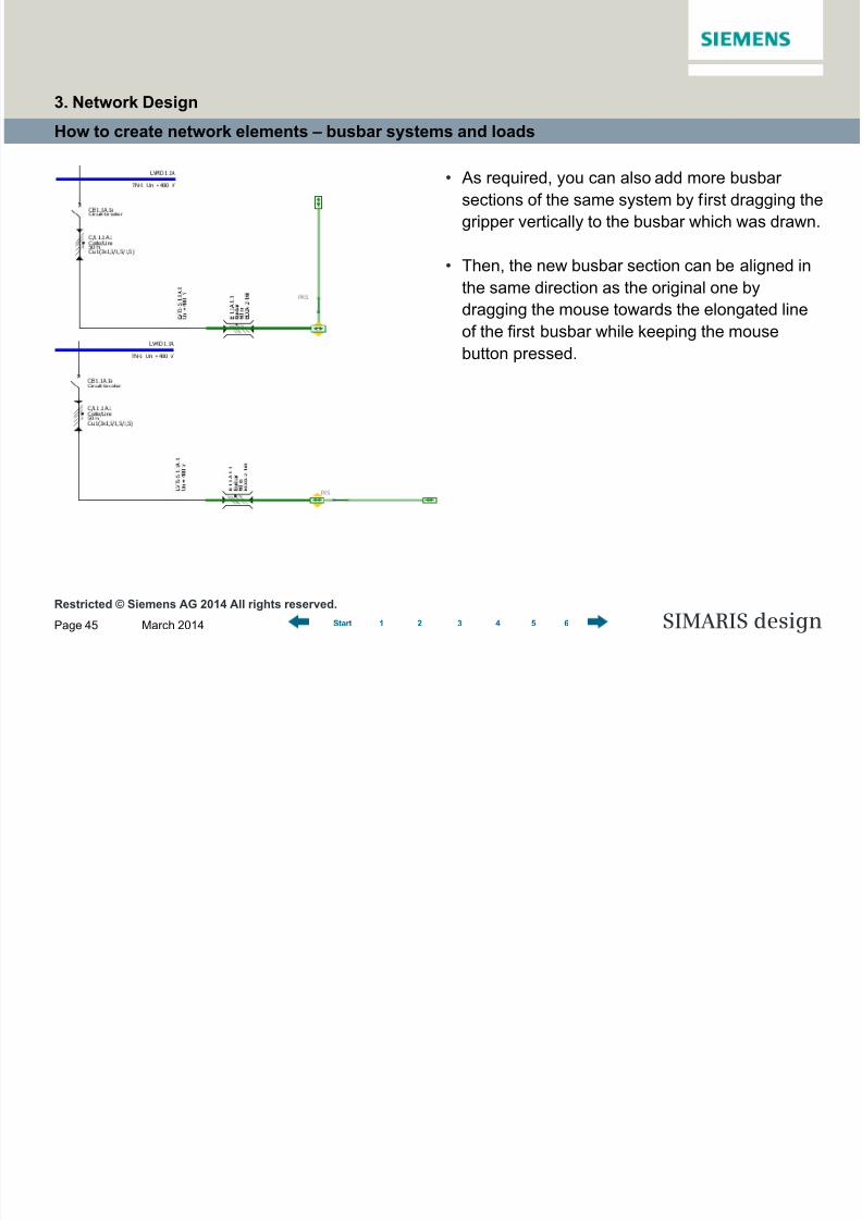
How to create network elements – busbar systems and loads
• As required, you can also add more busbar
sections of the same system by first dragging the
gripper vertically to the busbar which was drawn.
• Then, the new busbar section can be aligned in
the same direction as the original one by
dragging the mouse towards the elongated lineof the first busbar while keeping the mouse
button pressed.
3. Network Design

8/19/2019 Tutorial SIMARIS Design 8 En
http://slidepdf.com/reader/full/tutorial-simaris-design-8-en 46/114
Restricted © Siemens AG 2014 All rights reserved.March 2014Page 46 SIMARIS design1 2 3 4 5 6Start
How to create network elements – busbar systems and loads
Having clicked "Finish", the
following image can be seen on the
network diagram.
• As soon as the new busbar section has been
created and properly positioned on the diagram
by releasing the mouse button, the length of the
new busbar section must be specified.
3. Network Design

8/19/2019 Tutorial SIMARIS Design 8 En
http://slidepdf.com/reader/full/tutorial-simaris-design-8-en 47/114
Restricted © Siemens AG 2014 All rights reserved.March 2014Page 47 SIMARIS design1 2 3 4 5 6Start
How to create network elements – busbar systems and loads
• If you wish to change the type of a busbar
system already drawn on the network diagram at
a later stage in the planning process, because
requirements have changed in the meantime,
you can do so in the drop-down menu of the
properties displayed at the bottom left on screen
if you have marked the respective busbar(yellow line) in the graphics window.
3. Network Design
8/19/2019 Tutorial SIMARIS Design 8 En
http://slidepdf.com/reader/full/tutorial-simaris-design-8-en 48/114
Restricted © Siemens AG 2014 All rights reserved.March 2014Page 48 SIMARIS design1 2 3 4 5 6Start
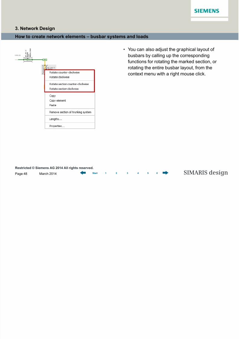
How to create network elements – busbar systems and loads
• You can also adjust the graphical layout of
busbars by calling up the corresponding
functions for rotating the marked section, or
rotating the entire busbar layout, from the
context menu with a right mouse click.
3. Network Design

8/19/2019 Tutorial SIMARIS Design 8 En
http://slidepdf.com/reader/full/tutorial-simaris-design-8-en 49/114
Restricted © Siemens AG 2014 All rights reserved.March 2014Page 49 SIMARIS design1 2 3 4 5 6Start
How to create network elements – busbar systems and loads
• After you have added and specified busbar
trunking systems, load circuits can be connected
to the busbars in the manner described above.
• If you connect more than one load circuit, the
distance of circuits from the starting point of the
busbar section must be defined for every load
circuit.
3. Network Design
8/19/2019 Tutorial SIMARIS Design 8 En
http://slidepdf.com/reader/full/tutorial-simaris-design-8-en 50/114
Restricted © Siemens AG 2014 All rights reserved.March 2014Page 50 SIMARIS design1 2 3 4 5 6Start
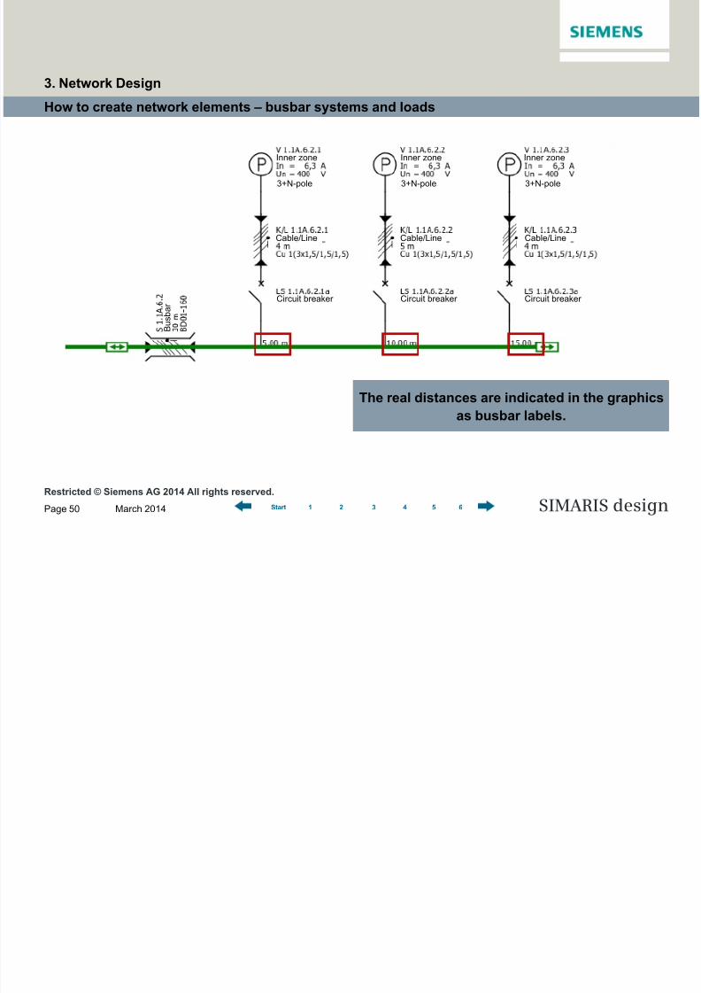
How to create network elements – busbar systems and loads
The real distances are indicated in the graphics
as busbar labels.
Circuit breakerCircuit breakerCircuit breaker
Inner zoneInner zoneInner zone
3+N-pole 3+N-pole 3+N-pole
Cable/Line Cable/Line Cable/Line
B u s b a r
3. Network Design
8/19/2019 Tutorial SIMARIS Design 8 En
http://slidepdf.com/reader/full/tutorial-simaris-design-8-en 51/114
Restricted © Siemens AG 2014 All rights reserved.March 2014Page 51 SIMARIS design1 2 3 4 5 6Start
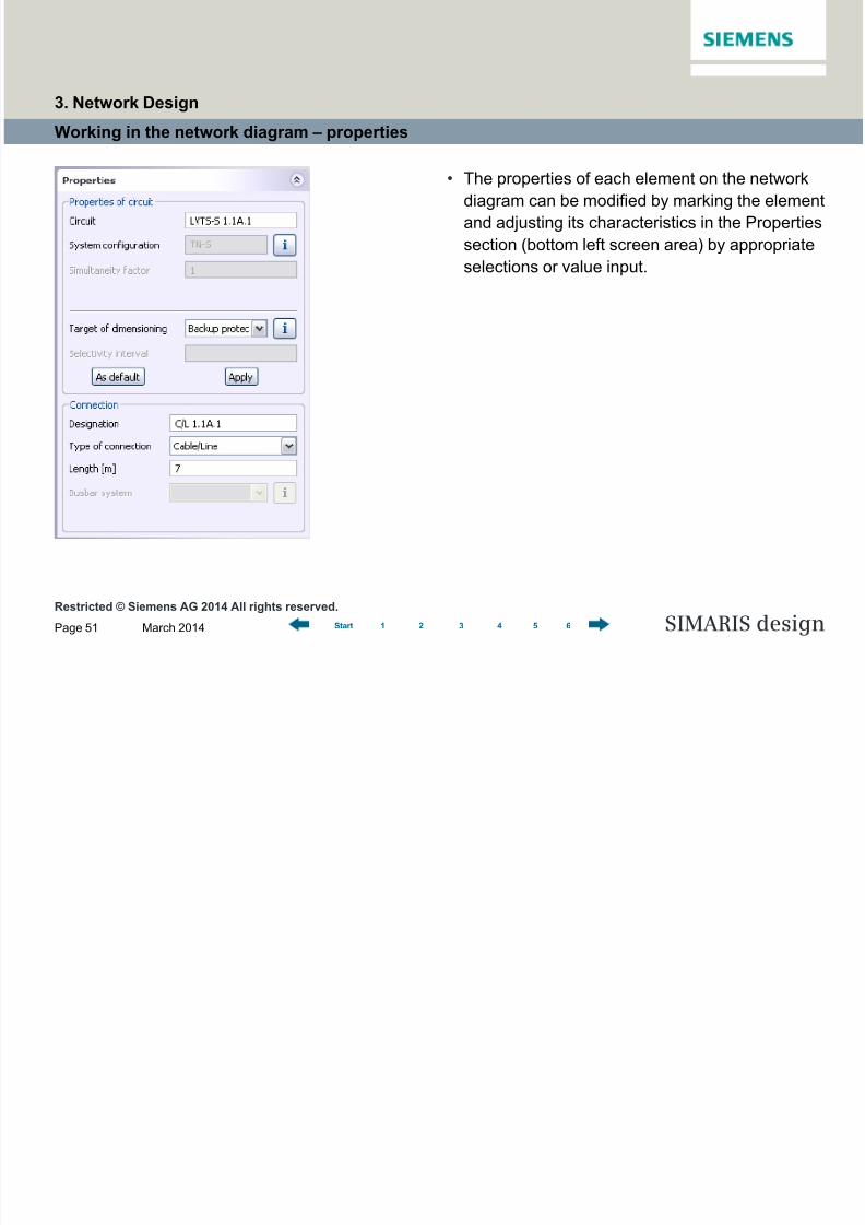
Working in the network diagram – properties
• The properties of each element on the network
diagram can be modified by marking the element
and adjusting its characteristics in the Properties
section (bottom left screen area) by appropriate
selections or value input.
3. Network Design

8/19/2019 Tutorial SIMARIS Design 8 En
http://slidepdf.com/reader/full/tutorial-simaris-design-8-en 52/114
Restricted © Siemens AG 2014 All rights reserved.March 2014Page 52 SIMARIS design1 2 3 4 5 6Start
Working in the network diagram – properties
Another possibility is opening the "Properties"
window by marking the element on the network
diagram and selecting "Properties" from the context
menu (right mouse button).
• This option is available both for switching
devices and fuses, that also applies to busbars
and cables/wires, for examples.• This allows to choose a different specification for
devices and items of equipment that have
already been specified in the automatic
dimensioning process.
3. Network Design
8/19/2019 Tutorial SIMARIS Design 8 En
http://slidepdf.com/reader/full/tutorial-simaris-design-8-en 53/114
Restricted © Siemens AG 2014 All rights reserved.March 2014Page 53 SIMARIS design1 2 3 4 5 6Start
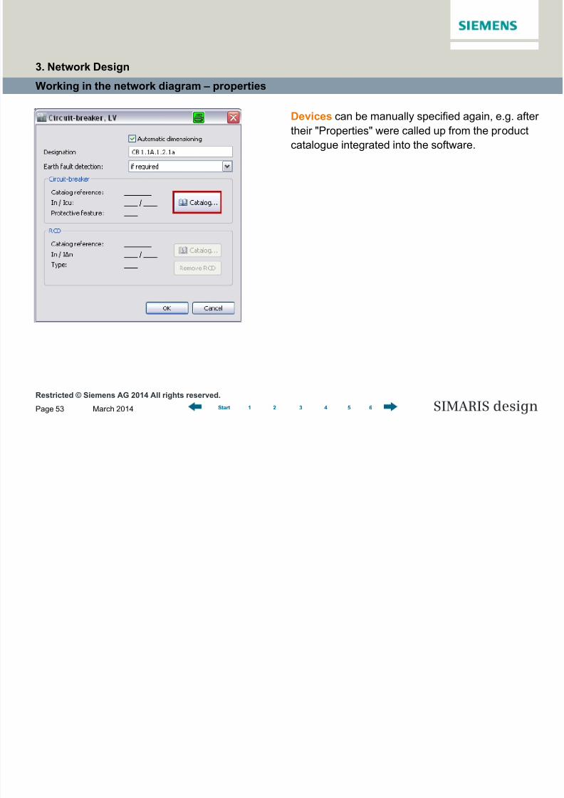
Working in the network diagram – properties
Devices can be manually specified again, e.g. after
their "Properties" were called up from the product
catalogue integrated into the software.
3. Network Design

8/19/2019 Tutorial SIMARIS Design 8 En
http://slidepdf.com/reader/full/tutorial-simaris-design-8-en 54/114
Restricted © Siemens AG 2014 All rights reserved.
March 2014Page 54 SIMARIS design1 2 3 4 5 6Start
Working in the network diagram – properties
In the product catalogue, a specification is made
based on the technical data that can be selected
on the right.
If the order number of the desired device is known,
the Product tree can also be searched directly
using the Search function at the top left of thedisplay.
3. Network Design
8/19/2019 Tutorial SIMARIS Design 8 En
http://slidepdf.com/reader/full/tutorial-simaris-design-8-en 55/114
Restricted © Siemens AG 2014 All rights reserved.
March 2014Page 55 SIMARIS design1 2 3 4 5 6Start
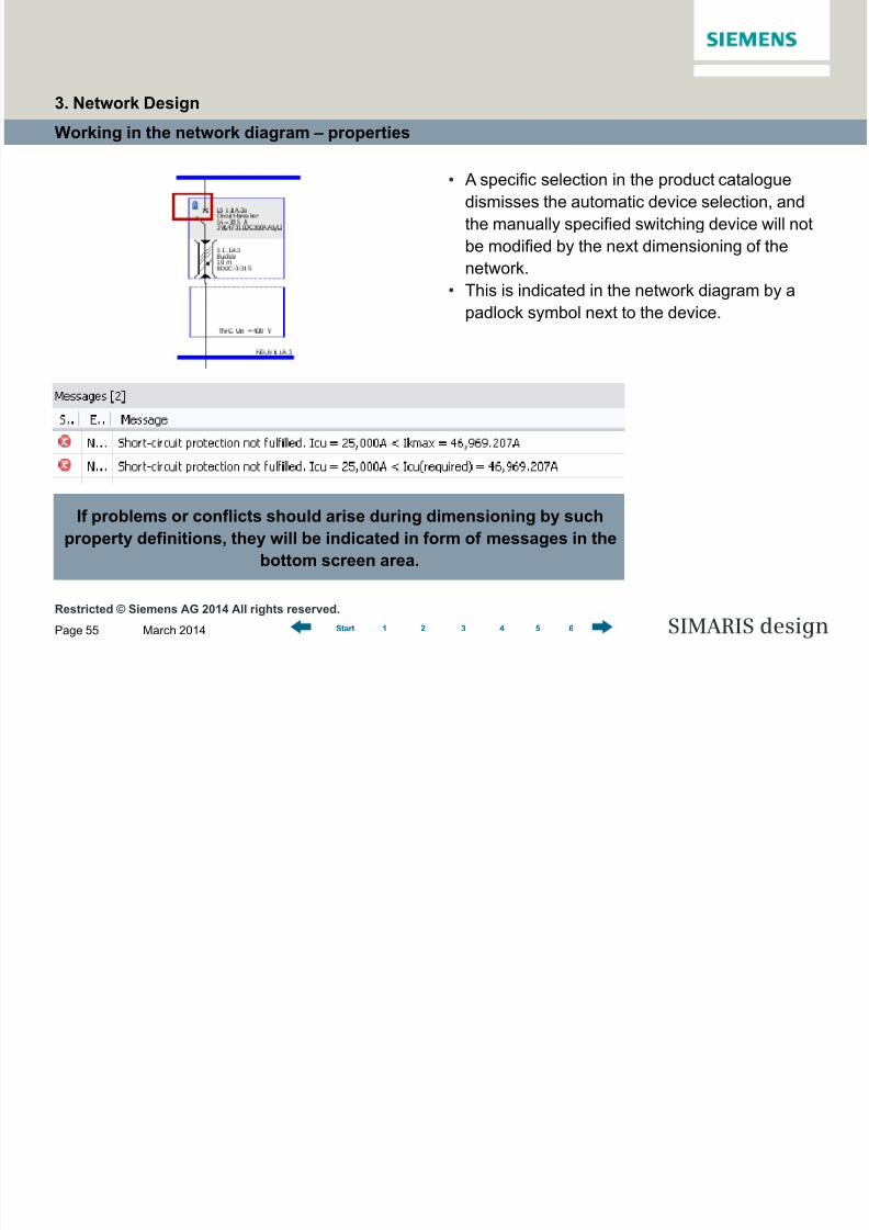
Working in the network diagram – properties
If problems or conflicts should arise during dimensioning by such
property definitions, they will be indicated in form of messages in the
bottom screen area.
• A specific selection in the product catalogue
dismisses the automatic device selection, and
the manually specified switching device will not
be modified by the next dimensioning of the
network.
• This is indicated in the network diagram by a
padlock symbol next to the device.
3. Network Design
8/19/2019 Tutorial SIMARIS Design 8 En
http://slidepdf.com/reader/full/tutorial-simaris-design-8-en 56/114
Restricted © Siemens AG 2014 All rights reserved.
March 2014Page 56 SIMARIS design1 2 3 4 5 6Start
Working in the network diagram – moving and aligning network elements
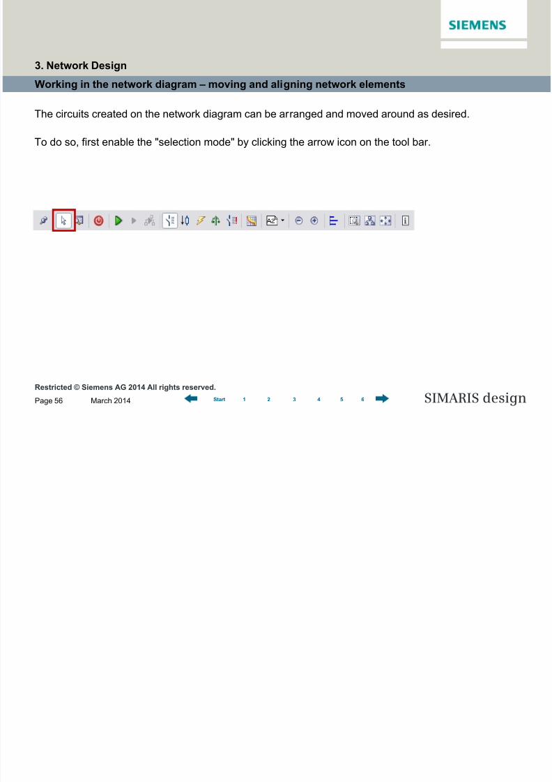
The circuits created on the network diagram can be arranged and moved around as desired.
To do so, first enable the "selection mode" by clicking the arrow icon on the tool bar.
3. Network Design

8/19/2019 Tutorial SIMARIS Design 8 En
http://slidepdf.com/reader/full/tutorial-simaris-design-8-en 57/114
Restricted © Siemens AG 2014 All rights reserved.
March 2014Page 57 SIMARIS design1 2 3 4 5 6Start
Working in the network diagram – moving and aligning network elements
• Another click into the marking (blue frame) while
keeping the mouse button pressed movesaround the entire circuit in the graphics.
• The connection lines to the other parts of the
network will be automatically redrawn after the
move operation.
• Now mark a circuit or a busbar trunking system
by left-clicking the circuit(= blue/green line turns yellow, mouse pointer
changes into crosshairs inside the marking).
……
3. Network Design
8/19/2019 Tutorial SIMARIS Design 8 En
http://slidepdf.com/reader/full/tutorial-simaris-design-8-en 58/114
Restricted © Siemens AG 2014 All rights reserved.
March 2014Page 58 SIMARIS design1 2 3 4 5 6Start
Working in the network diagram – moving and aligning network elements
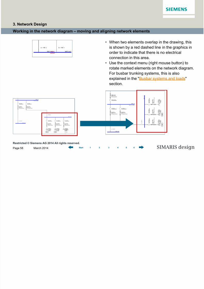
• When two elements overlap in the drawing, this
is shown by a red dashed line in the graphics in
order to indicate that there is no electrical
connection in this area.
• Use the context menu (right mouse button) to
rotate marked elements on the network diagram.
For busbar trunking systems, this is alsoexplained in the "Busbar systems and loads"
section.
3. Network Design
8/19/2019 Tutorial SIMARIS Design 8 En
http://slidepdf.com/reader/full/tutorial-simaris-design-8-en 59/114
Restricted © Siemens AG 2014 All rights reserved.
March 2014Page 59 SIMARIS design1 2 3 4 5 6Start
Working in the network diagram – moving and aligning network elements
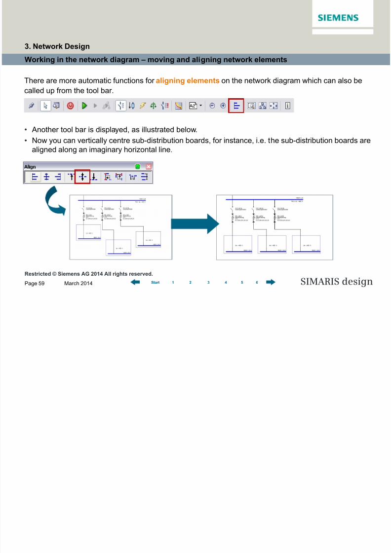
There are more automatic functions for aligning elements on the network diagram which can also be
called up from the tool bar.
• Another tool bar is displayed, as illustrated below.
• Now you can vertically centre sub-distribution boards, for instance, i.e. the sub-distribution boards arealigned along an imaginary horizontal line.
3. Network Design

8/19/2019 Tutorial SIMARIS Design 8 En
http://slidepdf.com/reader/full/tutorial-simaris-design-8-en 60/114
Restricted © Siemens AG 2014 All rights reserved.
March 2014Page 60 SIMARIS design1 2 3 4 5 6Start
Working in the network diagram – moving and aligning network elements
Or you can align elements to the left, by marking the respective elements and performing the align action.
3. Network Design

8/19/2019 Tutorial SIMARIS Design 8 En
http://slidepdf.com/reader/full/tutorial-simaris-design-8-en 61/114
Restricted © Siemens AG 2014 All rights reserved.
March 2014Page 61 SIMARIS design1 2 3 4 5 6Start
Working in the network diagram – copying and pasting
If you wish to place several identical elements at different positions on the network diagram, you can use
the Copy function.
For example, it can be called up
• by clicking the right mouse button,
• or by using the Windows-typical icons on the tool bar,
• or using keyboard shortcuts.
Please note that you have the option to copy entire
circuits (e.g. load circuits or sub-distribution
systems) and insert them at another position into
the network by
• first copying the element to be duplicated onto
the clipboard using the context menu(right mouse button),
• and enabling the copied element with another
right click and selecting "Paste"...
3. Network Design
8/19/2019 Tutorial SIMARIS Design 8 En
http://slidepdf.com/reader/full/tutorial-simaris-design-8-en 62/114
Restricted © Siemens AG 2014 All rights reserved.
March 2014Page 62 SIMARIS design1 2 3 4 5 6Start
Working in the network diagram – copying and pasting
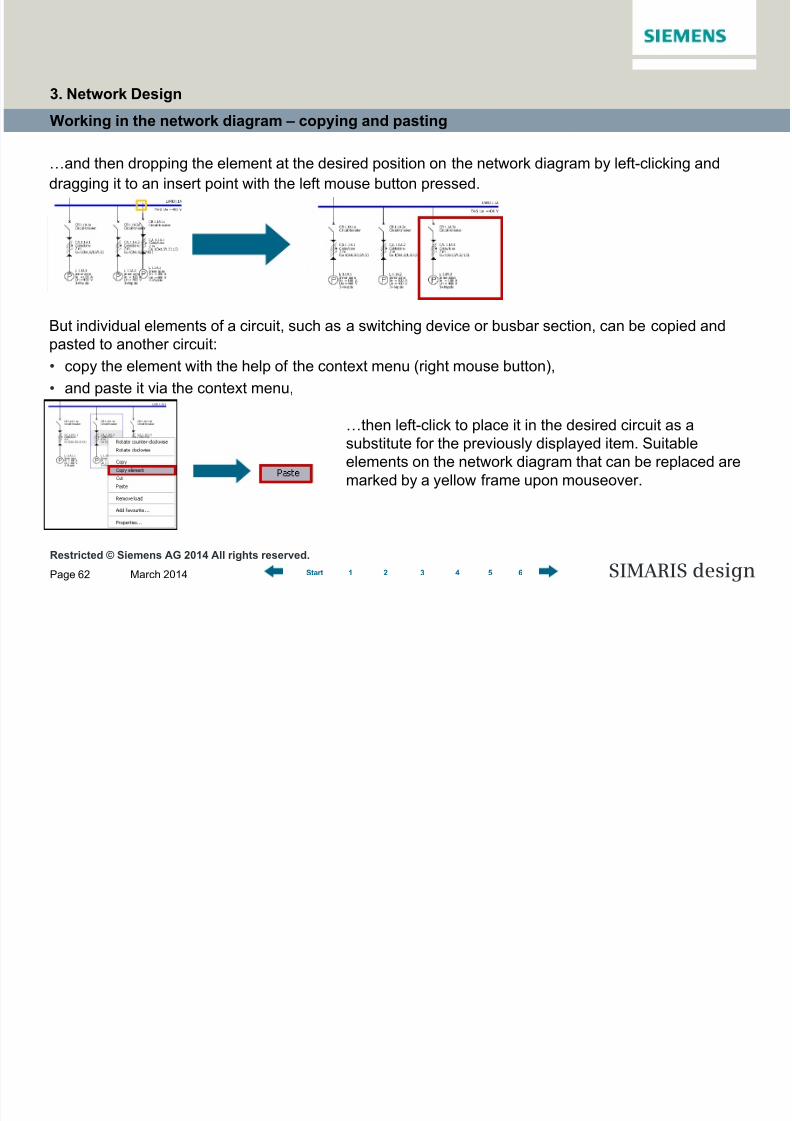
…and then dropping the element at the desired position on the network diagram by left-clicking and
dragging it to an insert point with the left mouse button pressed.
But individual elements of a circuit, such as a switching device or busbar section, can be copied and
pasted to another circuit:
• copy the element with the help of the context menu (right mouse button),
• and paste it via the context menu,
…then left-click to place it in the desired circuit as asubstitute for the previously displayed item. Suitable
elements on the network diagram that can be replaced are
marked by a yellow frame upon mouseover.
3. Network Design

8/19/2019 Tutorial SIMARIS Design 8 En
http://slidepdf.com/reader/full/tutorial-simaris-design-8-en 63/114
Restricted © Siemens AG 2014 All rights reserved.
March 2014Page 63 SIMARIS design1 2 3 4 5 6Start
Working in the network diagram – copying and pasting
…Then left-click to place it in the desired circuit as a substitute for the previously displayed item.
Suitable elements on the network diagram that can be replaced are marked by a yellow frame upon
mouseover.
Licensed users of SIMARIS design professional also have the option to copy entire networks, see
"Separate networks".
3. Network Design
8/19/2019 Tutorial SIMARIS Design 8 En
http://slidepdf.com/reader/full/tutorial-simaris-design-8-en 64/114
Restricted © Siemens AG 2014 All rights reserved.
March 2014Page 64 SIMARIS design1 2 3 4 5 6Start
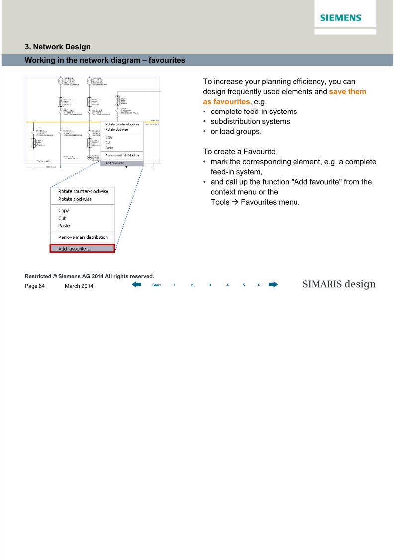
Working in the network diagram – favourites
To increase your planning efficiency, you can
design frequently used elements and save them
as favourites, e.g.
• complete feed-in systems
• subdistribution systems
• or load groups.
To create a Favourite
• mark the corresponding element, e.g. a complete
feed-in system,
• and call up the function "Add favourite" from the
context menu or the
Tools Favourites menu.
3. Network Design

8/19/2019 Tutorial SIMARIS Design 8 En
http://slidepdf.com/reader/full/tutorial-simaris-design-8-en 65/114
Restricted © Siemens AG 2014 All rights reserved.
March 2014Page 65 SIMARIS design1 2 3 4 5 6Start
Working in the network diagram – favourites
An input dialog is displayed where you can save a name and a description.
• Clicking "OK" saves the Favourite and
automatically sorts it into the matching category
as system infeed, distribution board or final
circuit.
• To reuse the Favourite, you must select the
Favourites tab instead of the Library.
3. Network Design
8/19/2019 Tutorial SIMARIS Design 8 En
http://slidepdf.com/reader/full/tutorial-simaris-design-8-en 66/114
Restricted © Siemens AG 2014 All rights reserved.
March 2014Page 66 SIMARIS design1 2 3 4 5 6Start
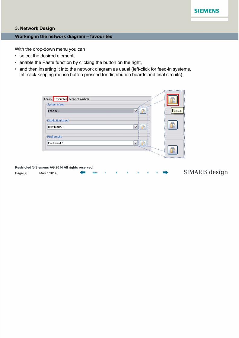
Working in the network diagram – favourites
With the drop-down menu you can
• select the desired element,
• enable the Paste function by clicking the button on the right,
• and then inserting it into the network diagram as usual (left-click for feed-in systems,
left-click keeping mouse button pressed for distribution boards and final circuits).
3. Network Design
8/19/2019 Tutorial SIMARIS Design 8 En
http://slidepdf.com/reader/full/tutorial-simaris-design-8-en 67/114
Restricted © Siemens AG 2014 All rights reserved.
March 2014Page 67 SIMARIS design1 2 3 4 5 6Start
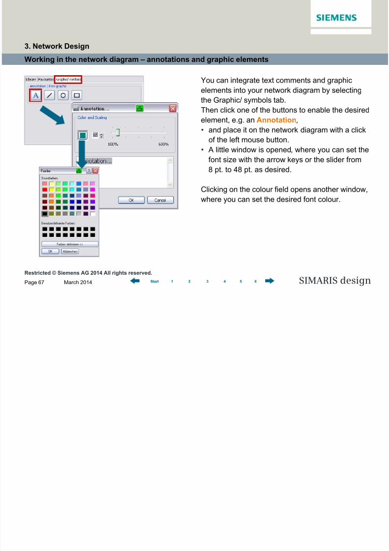
Working in the network diagram – annotations and graphic elements
You can integrate text comments and graphic
elements into your network diagram by selecting
the Graphic/ symbols tab.
Then click one of the buttons to enable the desired
element, e.g. an Annotation,
• and place it on the network diagram with a click
of the left mouse button.• A little window is opened, where you can set the
font size with the arrow keys or the slider from
8 pt. to 48 pt. as desired.
Clicking on the colour field opens another window,
where you can set the desired font colour.
3. Network Design

8/19/2019 Tutorial SIMARIS Design 8 En
http://slidepdf.com/reader/full/tutorial-simaris-design-8-en 68/114
Restricted © Siemens AG 2014 All rights reserved.
March 2014Page 68 SIMARIS design1 2 3 4 5 6Start
Working in the network diagram – annotations and graphic elements
• When all settings are made, the annotation is
placed on the network diagram at the previously
selected position, as soon as you click "OK".
• If you would like to re-edit the annotation later,
open the above dialog again from the context
menu (right mouse button) and select "Editannotation".
3. Network Design

8/19/2019 Tutorial SIMARIS Design 8 En
http://slidepdf.com/reader/full/tutorial-simaris-design-8-en 69/114
Restricted © Siemens AG 2014 All rights reserved.
March 2014Page 69 SIMARIS design1 2 3 4 5 6Start
Working in the network diagram – annotations and graphic elements
In a similar way, you can add lines, circles/
ellipses and rectangles .
• When you select the appropriate icon, the cursor
turns into crosshairs as soon as it is moved into
the network diagram.
• Left-clicking places the graphic symbol in the
network diagram. It can be zoomed up bydragging the mouse with the left mouse button
pressed.
Once it is placed, the graphic element can still be
readjusted by
• marking it,
• moving the mouse onto one of the little yellow
boxes
• and then dragging it into one of the directions
indicated by the arrow, keeping the left mouse
button pressed.
3. Network Design
8/19/2019 Tutorial SIMARIS Design 8 En
http://slidepdf.com/reader/full/tutorial-simaris-design-8-en 70/114
Restricted © Siemens AG 2014 All rights reserved.
March 2014Page 70 SIMARIS design1 2 3 4 5 6Start
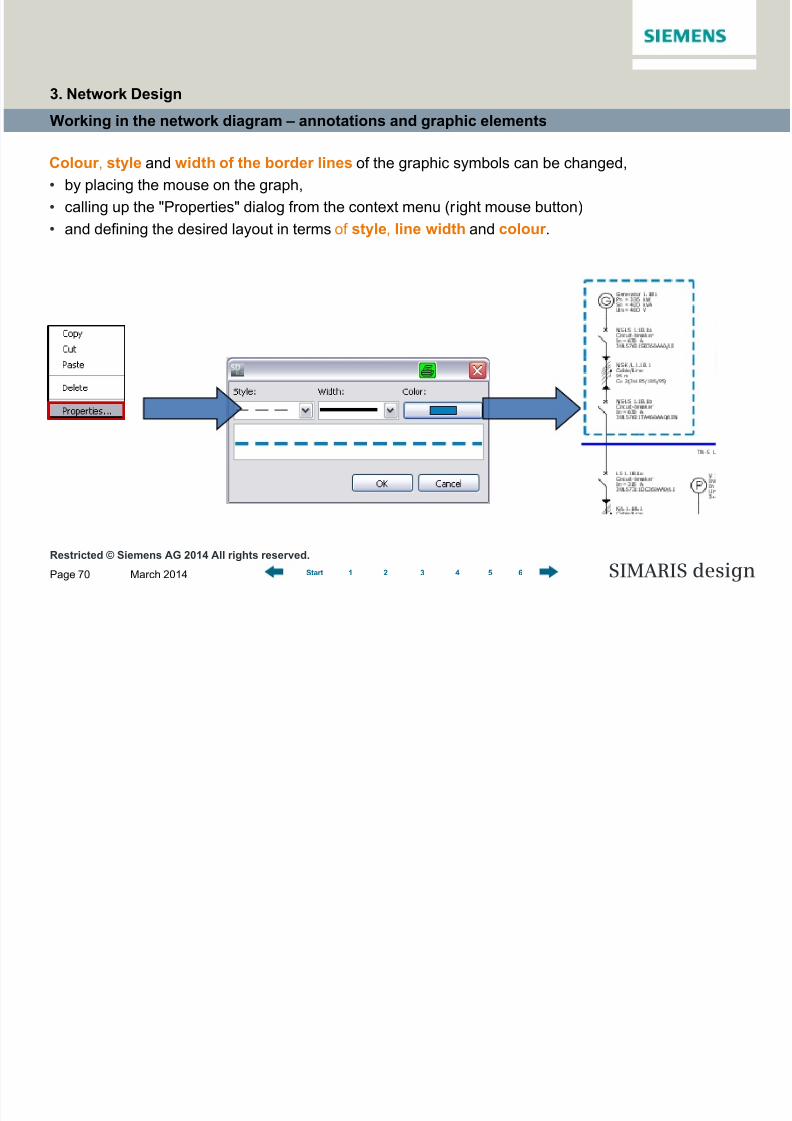
Working in the network diagram – annotations and graphic elements
Colour , style and width of the border lines of the graphic symbols can be changed,
• by placing the mouse on the graph,
• calling up the "Properties" dialog from the context menu (right mouse button)
• and defining the desired layout in terms of style, line width and colour .
3. Network Design
8/19/2019 Tutorial SIMARIS Design 8 En
http://slidepdf.com/reader/full/tutorial-simaris-design-8-en 71/114
Restricted © Siemens AG 2014 All rights reserved.
March 2014Page 71 SIMARIS design1 2 3 4 5 6Start
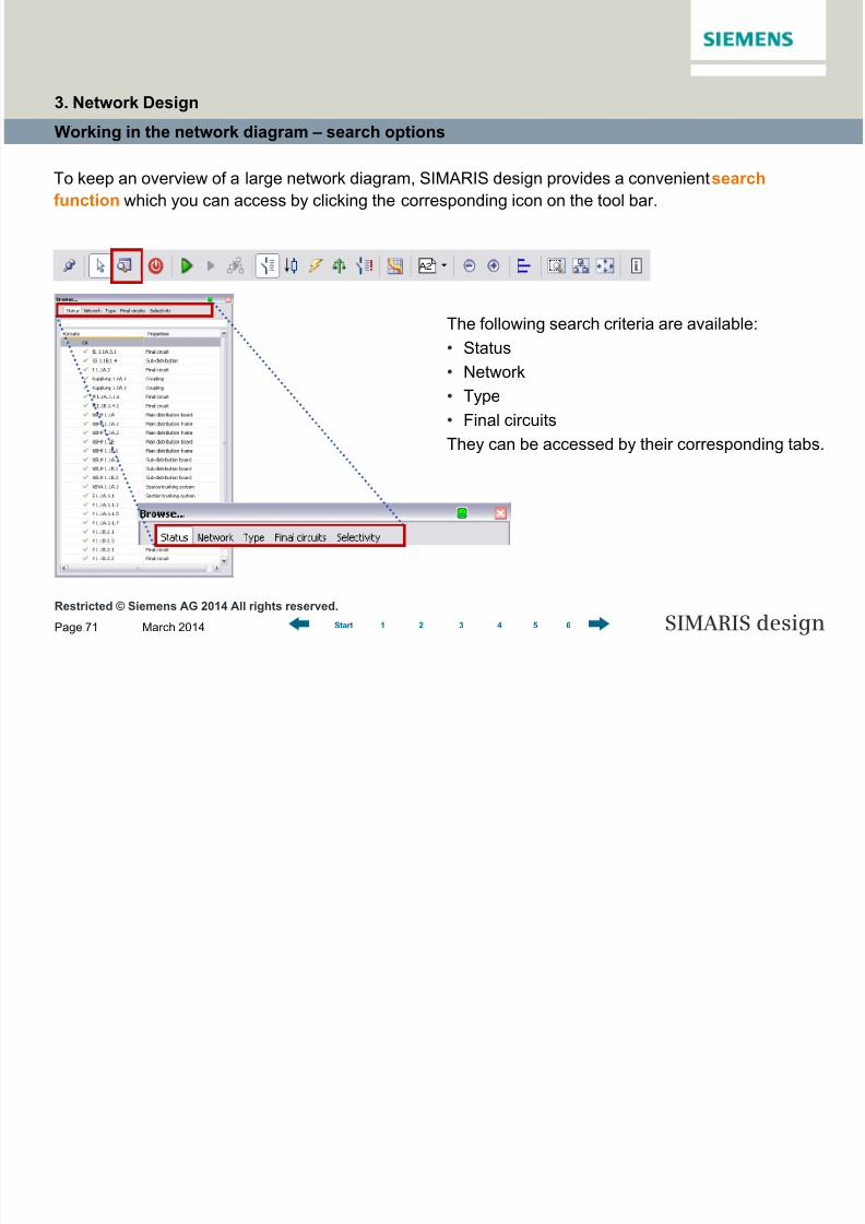
Working in the network diagram – search options
To keep an overview of a large network diagram, SIMARIS design provides a convenient search
function which you can access by clicking the corresponding icon on the tool bar.
The following search criteria are available:
• Status
• Network
• Type
• Final circuits
They can be accessed by their corresponding tabs.
3. Network Design

8/19/2019 Tutorial SIMARIS Design 8 En
http://slidepdf.com/reader/full/tutorial-simaris-design-8-en 72/114
Restricted © Siemens AG 2014 All rights reserved.
March 2014Page 72 SIMARIS design1 2 3 4 5 6Start
Working in the network diagram – search options
• The Status tab lists all circuits and sorts them
according to the criterion whether they are still
subject to errors or not, or whether there are still
info messages/notes linked to them.
• When you mark a circuit in the list view with the
cursor, it is marked in the graphics window as well
(blue frame).
3. Network Design

8/19/2019 Tutorial SIMARIS Design 8 En
http://slidepdf.com/reader/full/tutorial-simaris-design-8-en 73/114
Restricted © Siemens AG 2014 All rights reserved.
March 2014Page 73 SIMARIS design1 2 3 4 5 6Start
Working in the network diagram – search options
The Network tab displays all
elements of the network diagram
in a tree structure, also marking
faulty elements as such.
You can search for circuits
according to Type.
Final circuits may be used
as search criterion as well.
3. Network Design

8/19/2019 Tutorial SIMARIS Design 8 En
http://slidepdf.com/reader/full/tutorial-simaris-design-8-en 74/114
Restricted © Siemens AG 2014 All rights reserved.
March 2014Page 74 SIMARIS design1 2 3 4 5 6Start
Working in the network diagram – search options
In addition, you have the option as user of
SIMARIS design professional to search you
network diagram according to the Selectivity
criterion.
3. Network Design

8/19/2019 Tutorial SIMARIS Design 8 En
http://slidepdf.com/reader/full/tutorial-simaris-design-8-en 75/114
Restricted © Siemens AG 2014 All rights reserved.
March 2014Page 75 SIMARIS design1 2 3 4 5 6Start
Working in the network diagram – search options
Another search option is the entry of an element name – possibly adapted by you
(in our example a motor group).
3. Network Design

8/19/2019 Tutorial SIMARIS Design 8 En
http://slidepdf.com/reader/full/tutorial-simaris-design-8-en 76/114
Restricted © Siemens AG 2014 All rights reserved.
March 2014Page 76 SIMARIS design1 2 3 4 5 6Start
Couplings
Mapping couplings in the network diagram is possible, both for
• general couplings, where bidirectional energy flow is possible,
• and for unidirectional couplings, where energy flow has been defined in one direction only.
You are able to map both normal and emergency power supply.
Note:
In order to be able to dimension such a complex feed-in system using couplings, you must define theoperating modes for the feed-in system first.
This must be done after the complete feed-in system has been created. Use the "Operating modes"
icon on the tool bar. For more detailed information, please refer to "Dimensioning".
3. Network Design
8/19/2019 Tutorial SIMARIS Design 8 En
http://slidepdf.com/reader/full/tutorial-simaris-design-8-en 77/114
Restricted © Siemens AG 2014 All rights reserved.
March 2014Page 77 SIMARIS design1 2 3 4 5 6Start
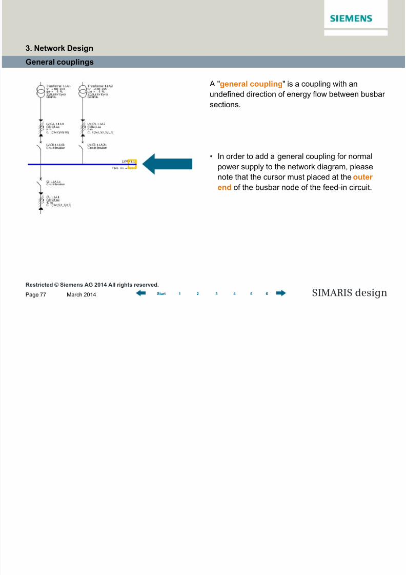
General couplings
A "general coupling" is a coupling with an
undefined direction of energy flow between busbar
sections.
• In order to add a general coupling for normal
power supply to the network diagram, please
note that the cursor must placed at the outer
end of the busbar node of the feed-in circuit.
3. Network Design
8/19/2019 Tutorial SIMARIS Design 8 En
http://slidepdf.com/reader/full/tutorial-simaris-design-8-en 78/114
Restricted © Siemens AG 2014 All rights reserved.
March 2014Page 78 SIMARIS design1 2 3 4 5 6Start
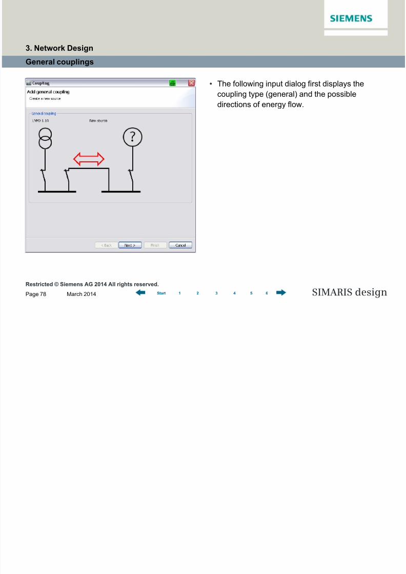
General couplings
• The following input dialog first displays the
coupling type (general) and the possible
directions of energy flow.
3. Network Design
8/19/2019 Tutorial SIMARIS Design 8 En
http://slidepdf.com/reader/full/tutorial-simaris-design-8-en 79/114
Restricted © Siemens AG 2014 All rights reserved.
March 2014Page 79 SIMARIS design1 2 3 4 5 6Start
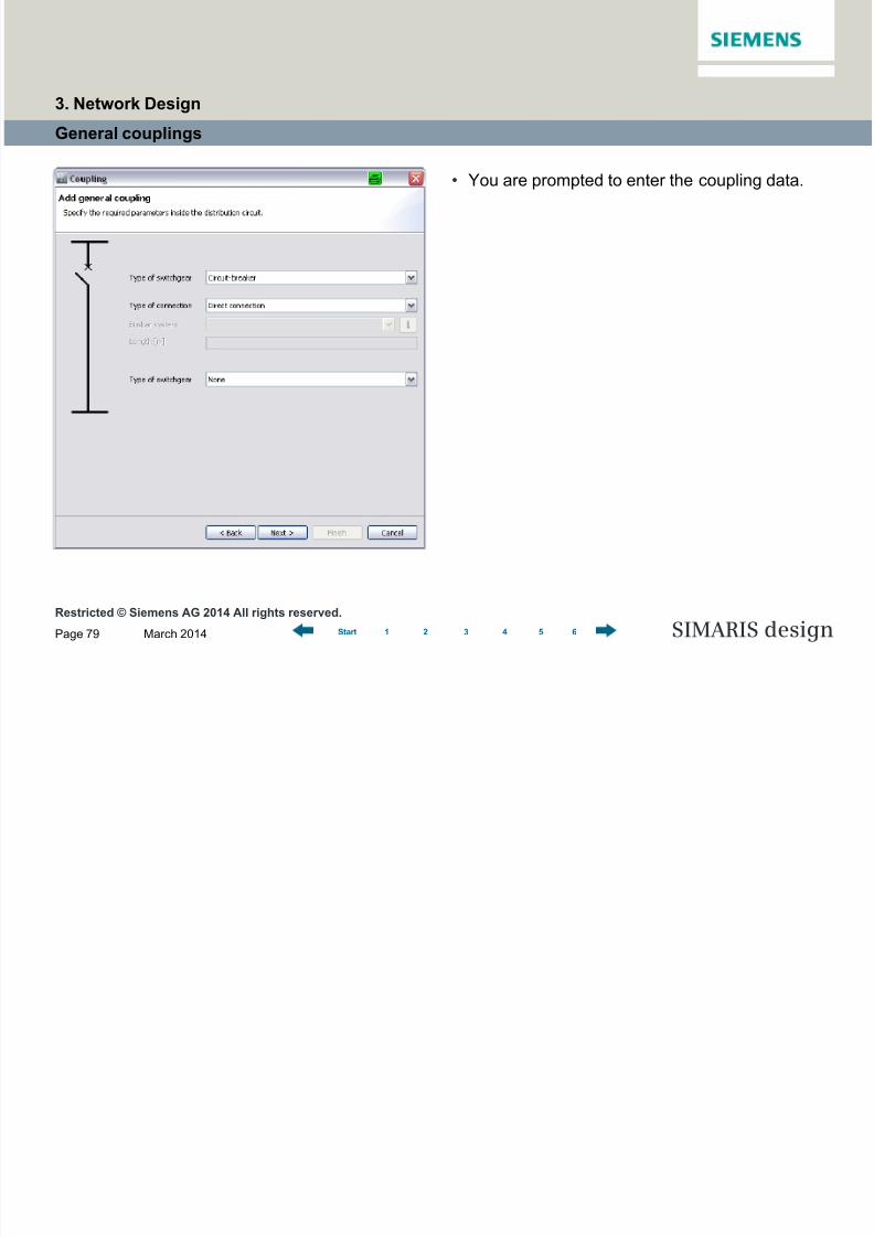
General couplings
• You are prompted to enter the coupling data.
3. Network Design
8/19/2019 Tutorial SIMARIS Design 8 En
http://slidepdf.com/reader/full/tutorial-simaris-design-8-en 80/114
Restricted © Siemens AG 2014 All rights reserved.
March 2014Page 80 SIMARIS design1 2 3 4 5 6Start
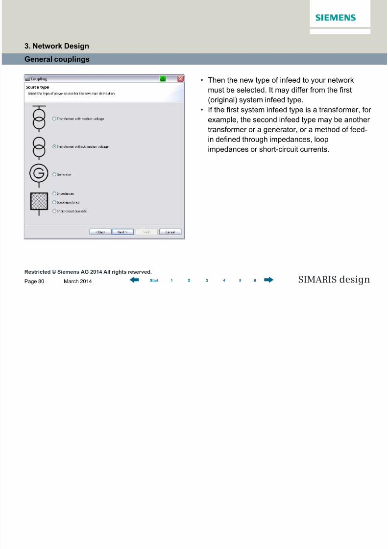
General couplings
• Then the new type of infeed to your network
must be selected. It may differ from the first
(original) system infeed type.
• If the first system infeed type is a transformer, for
example, the second infeed type may be another
transformer or a generator, or a method of feed-
in defined through impedances, loopimpedances or short-circuit currents.
3. Network Design

8/19/2019 Tutorial SIMARIS Design 8 En
http://slidepdf.com/reader/full/tutorial-simaris-design-8-en 81/114
Restricted © Siemens AG 2014 All rights reserved.
March 2014Page 81 SIMARIS design1 2 3 4 5 6Start
General couplings
• Now you must define the data required for the
selected type of second infeed, in this case it is a
transformer without medium voltage.
3. Network Design
8/19/2019 Tutorial SIMARIS Design 8 En
http://slidepdf.com/reader/full/tutorial-simaris-design-8-en 82/114
Restricted © Siemens AG 2014 All rights reserved.
March 2014Page 82 SIMARIS design1 2 3 4 5 6Start
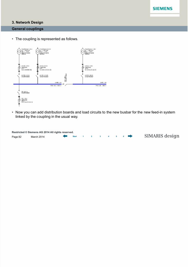
General couplings
• The coupling is represented as follows.
• Now you can add distribution boards and load circuits to the new busbar for the new feed-in system
linked by the coupling in the usual way.
3. Network Design

8/19/2019 Tutorial SIMARIS Design 8 En
http://slidepdf.com/reader/full/tutorial-simaris-design-8-en 83/114
Restricted © Siemens AG 2014 All rights reserved.
March 2014Page 83 SIMARIS design1 2 3 4 5 6Start
Unidirectional couplings
• In a unidirectional coupling, the direction of
energy flow between busbar section has been
defined.
• This can be employed to map combinations of
normal and emergency/safety power supply
(e.g. between transformer- and generator-
supplied networks).• Please note that the cursor for adding a coupling
to the network diagram must not be placed at the
outer busbar end, but at one of the inner insert
points of the busbar for the infeed circuit.
3. Network Design

8/19/2019 Tutorial SIMARIS Design 8 En
http://slidepdf.com/reader/full/tutorial-simaris-design-8-en 84/114
Restricted © Siemens AG 2014 All rights reserved.
March 2014Page 84 SIMARIS design1 2 3 4 5 6Start
Unidirectional couplings
• In the following input dialog, you must define which of the feed-in systems is the emergency supply
circuit. This way, you also determine the direction of energy flow.
3. Network Design

8/19/2019 Tutorial SIMARIS Design 8 En
http://slidepdf.com/reader/full/tutorial-simaris-design-8-en 85/114
Restricted © Siemens AG 2014 All rights reserved.
March 2014Page 85 SIMARIS design1 2 3 4 5 6Start
Unidirectional couplings
• You are prompted to enter or select more
technical data for the coupling.
3. Network Design
8/19/2019 Tutorial SIMARIS Design 8 En
http://slidepdf.com/reader/full/tutorial-simaris-design-8-en 86/114
Restricted © Siemens AG 2014 All rights reserved.
March 2014Page 86 SIMARIS design1 2 3 4 5 6Start
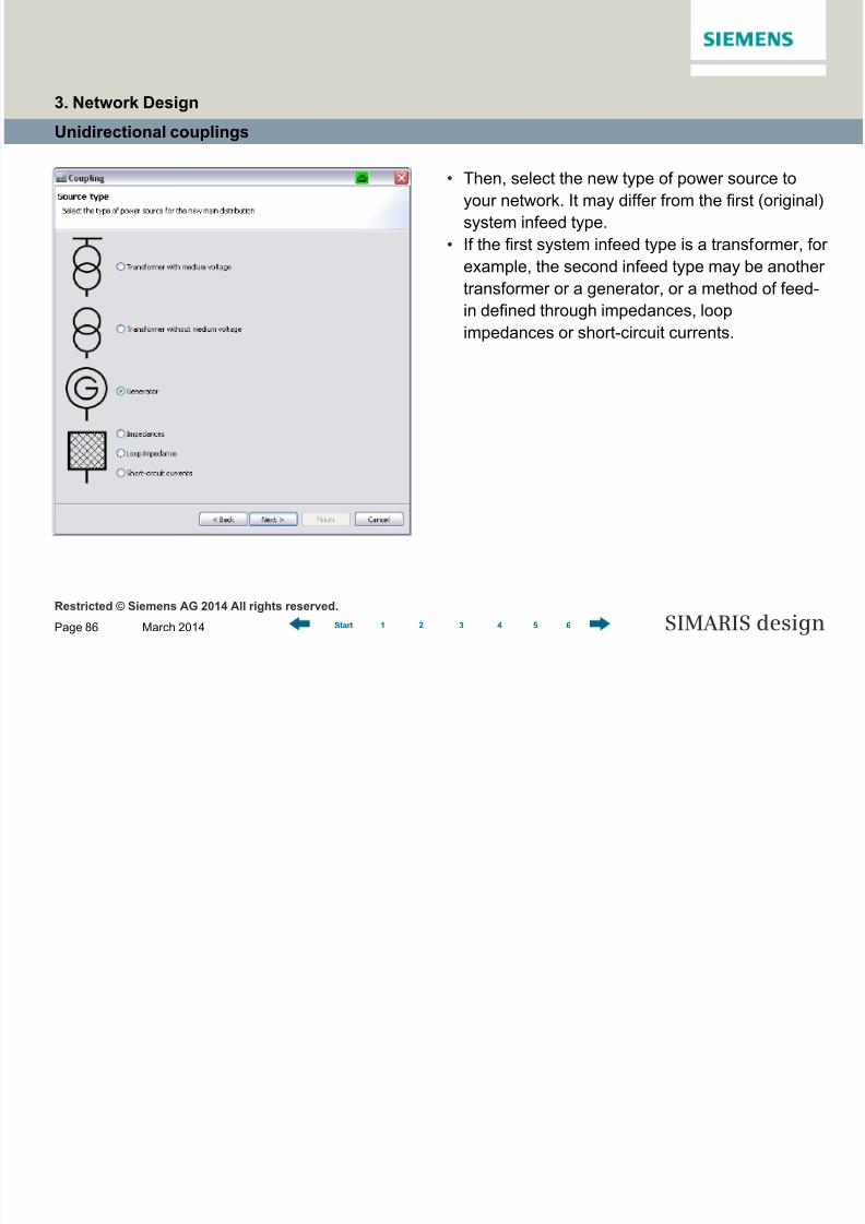
Unidirectional couplings
• Then, select the new type of power source to
your network. It may differ from the first (original)
system infeed type.
• If the first system infeed type is a transformer, for
example, the second infeed type may be another
transformer or a generator, or a method of feed-
in defined through impedances, loopimpedances or short-circuit currents.
3. Network Design

8/19/2019 Tutorial SIMARIS Design 8 En
http://slidepdf.com/reader/full/tutorial-simaris-design-8-en 87/114
Restricted © Siemens AG 2014 All rights reserved.
March 2014Page 87 SIMARIS design1 2 3 4 5 6Start
Unidirectional couplings
• Now you must define the data required for the
selected type of second infeed, in this case it is
a generator.
3. Network Design

8/19/2019 Tutorial SIMARIS Design 8 En
http://slidepdf.com/reader/full/tutorial-simaris-design-8-en 88/114
Restricted © Siemens AG 2014 All rights reserved.
March 2014Page 88 SIMARIS design1 2 3 4 5 6Start
Unidirectional couplings
• The coupling is represented as follows. The direction of energy flow is indicated by little arrows.
• Now you can add distribution boards and load circuits to the busbar for the new feed-in system linked
by the coupling in the usual way.
3. Network Design
8/19/2019 Tutorial SIMARIS Design 8 En
http://slidepdf.com/reader/full/tutorial-simaris-design-8-en 89/114
Restricted © Siemens AG 2014 All rights reserved.
March 2014Page 89 SIMARIS design1 2 3 4 5 6Start
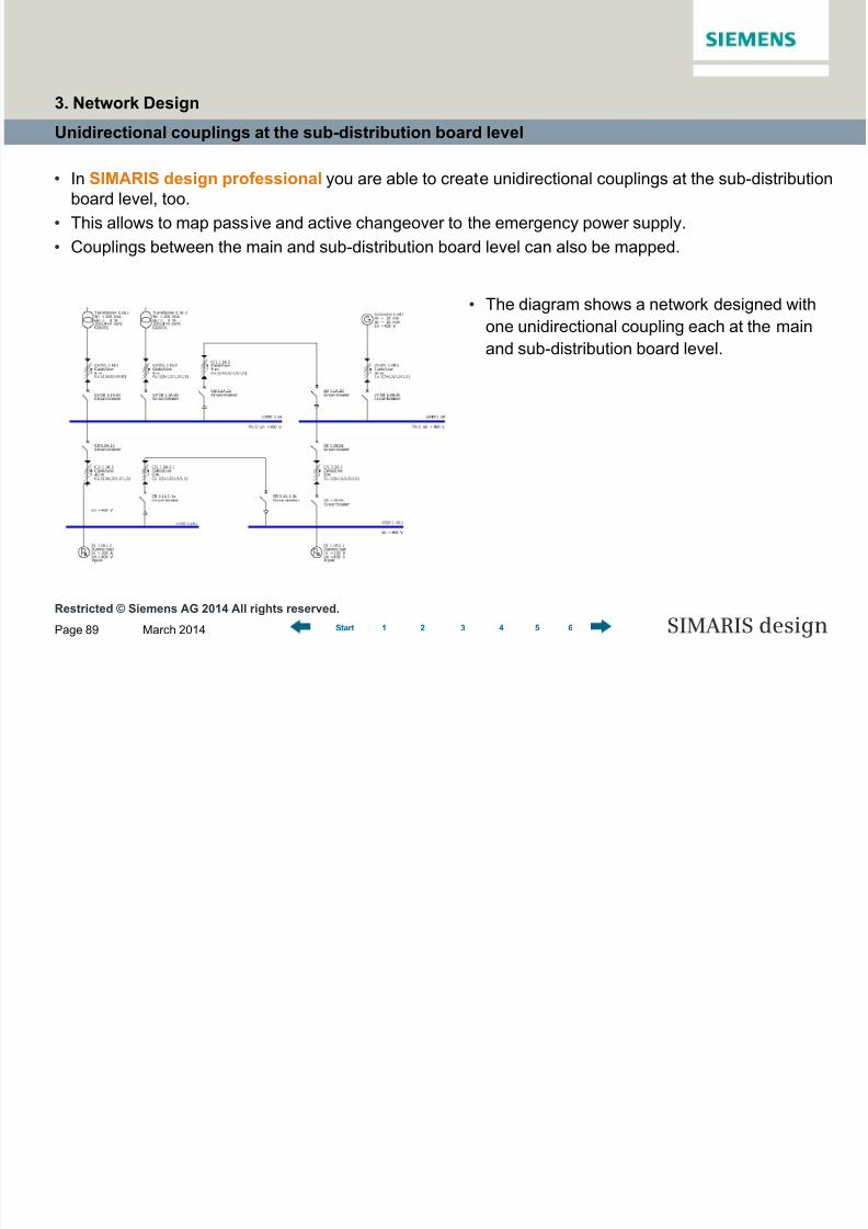
Unidirectional couplings at the sub-distribution board level
• The diagram shows a network designed with
one unidirectional coupling each at the main
and sub-distribution board level.
• In SIMARIS design professional you are able to create unidirectional couplings at the sub-distribution
board level, too.
• This allows to map passive and active changeover to the emergency power supply.
• Couplings between the main and sub-distribution board level can also be mapped.
3. Network Design
8/19/2019 Tutorial SIMARIS Design 8 En
http://slidepdf.com/reader/full/tutorial-simaris-design-8-en 90/114
Page 90
Software for efficient dimensioningof power distribution systems
SIMARIS design
SIMARIS design Tutorial
1 Introduction
2 Getting Started
3 Network Design
4 Dimensioning
5 Project Output
6 More about SIMARIS
1 2 3 4 5 6Start
Defining operating modesStarting calculations
Parallel network operation (pro)
Displaying characteristic curves
Automatic selectivity evaluation (pro)
4 Dimensioning

8/19/2019 Tutorial SIMARIS Design 8 En
http://slidepdf.com/reader/full/tutorial-simaris-design-8-en 91/114
Restricted © Siemens AG 2014 All rights reserved.
March 2014Page 91 SIMARIS design1 2 3 4 5 6Start
Defining operating modes
• SIMARIS design enables you to dimension individual circuits, a subnetwork or the whole network.
• An optimal dimensioning result can be attained by considering only those operating states or switch
positions in the calculation and device selection that are necessary for operating the switchgear
installation safely.
• This means that the prerequisite for proper network dimensioning is the definition of network operating
modes and the corresponding switch positions.
• When the "operating modes" function is called up via the tool bar, a display of the feeder supply
management is opened, where the required operating modes are graphically represented and can be
further defined in terms of their switch positions.
4. Dimensioning

8/19/2019 Tutorial SIMARIS Design 8 En
http://slidepdf.com/reader/full/tutorial-simaris-design-8-en 92/114
Restricted © Siemens AG 2014 All rights reserved.
March 2014Page 92 SIMARIS design1 2 3 4 5 6Start
Defining operating modes
• At first, only the structure of the configured infeed
system is displayed. The switch position required
for this particular operating mode can still be set
by clicking on the switch symbol (open – closed).
4. Dimensioning
8/19/2019 Tutorial SIMARIS Design 8 En
http://slidepdf.com/reader/full/tutorial-simaris-design-8-en 93/114
Restricted © Siemens AG 2014 All rights reserved.
March 2014Page 93 SIMARIS design1 2 3 4 5 6Start
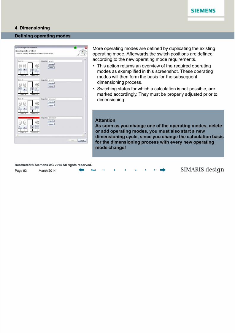
Defining operating modes
Attention:
As soon as you change one of the operating modes, deleteor add operating modes, you must also start a new
dimensioning cycle, since you change the calculation basis
for the dimensioning process with every new operating
mode change!
More operating modes are defined by duplicating the existing
operating mode. Afterwards the switch positions are defined
according to the new operating mode requirements.
• This action returns an overview of the required operating
modes as exemplified in this screenshot. These operating
modes will then form the basis for the subsequent
dimensioning process.
• Switching states for which a calculation is not possible, are
marked accordingly. They must be properly adjusted prior to
dimensioning.
4. Dimensioning
8/19/2019 Tutorial SIMARIS Design 8 En
http://slidepdf.com/reader/full/tutorial-simaris-design-8-en 94/114
Restricted © Siemens AG 2014 All rights reserved.
March 2014Page 94 SIMARIS design1 2 3 4 5 6Start
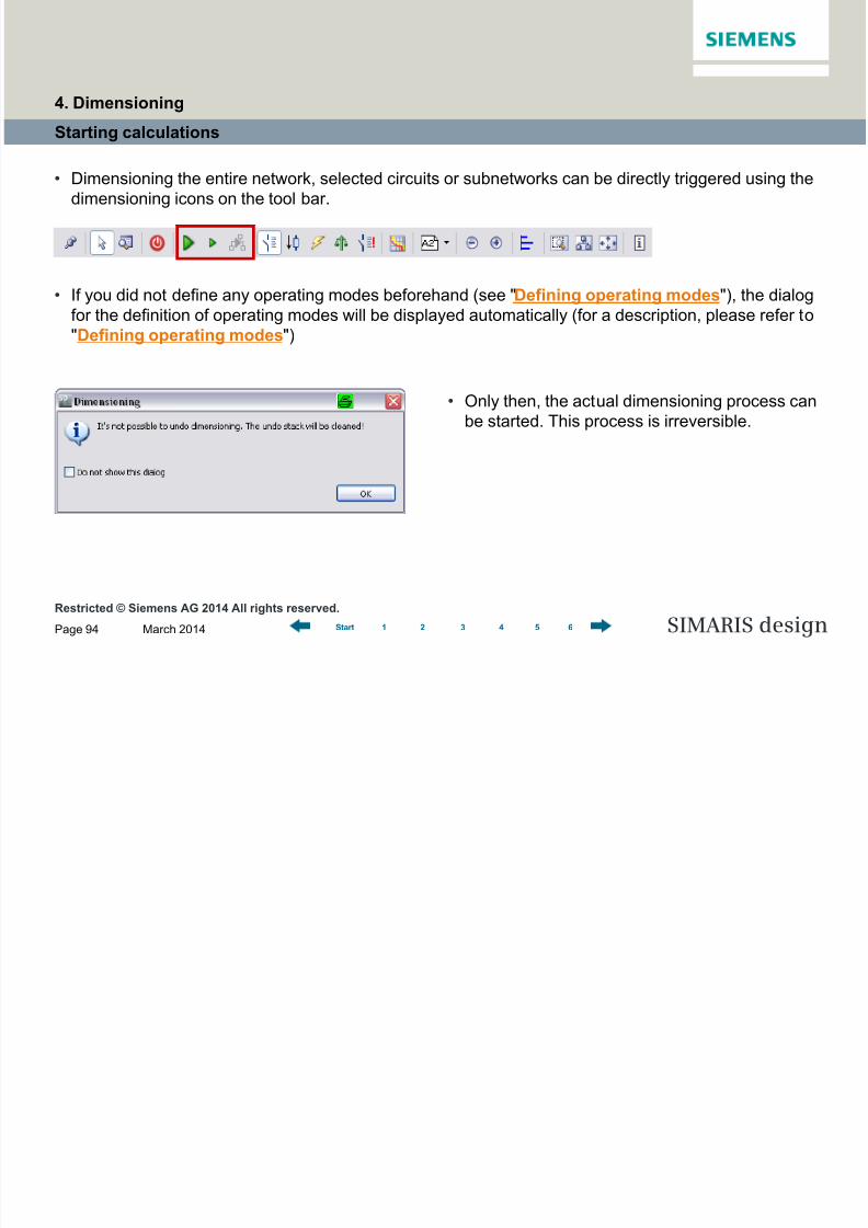
Starting calculations
• Dimensioning the entire network, selected circuits or subnetworks can be directly triggered using the
dimensioning icons on the tool bar.
• If you did not define any operating modes beforehand (see "Defining operating modes"), the dialog
for the definition of operating modes will be displayed automatically (for a description, please refer to"Defining operating modes")
• Only then, the actual dimensioning process can
be started. This process is irreversible.
4. Dimensioning
8/19/2019 Tutorial SIMARIS Design 8 En
http://slidepdf.com/reader/full/tutorial-simaris-design-8-en 95/114
Restricted © Siemens AG 2014 All rights reserved.
March 2014Page 95 SIMARIS design1 2 3 4 5 6Start
Starting calculations
• Dimensioning and the resulting device selection are performed according to defined operating
constellations. Thus an optimized dimensioning result is attained.
• SIMARIS design calculates the minimum and maximum short-circuit currents from all defined
operating modes, this calculation forms the basis for dimensioning the entire network.
•
Complex network configurations can be easily implemented with the aid of tie breakers or buscouplers, also see "Couplings".
4. Dimensioning

8/19/2019 Tutorial SIMARIS Design 8 En
http://slidepdf.com/reader/full/tutorial-simaris-design-8-en 96/114
Restricted © Siemens AG 2014 All rights reserved.
March 2014Page 96 SIMARIS design1 2 3 4 5 6Start
Starting calculations
4. Dimensioning
• If errors should occur during the dimensioning process, e.g. owing to default devices which do not
meet the requirements for the defined operating modes, info and error messages will be displayed
below the network diagram.
• If one of the messages is selected with the cursor (now highlighted in grey), the corresponding device
is marked in yellow on the network diagram so that a correlation can always be created between
messages and items of equipment in the network diagram.
8/19/2019 Tutorial SIMARIS Design 8 En
http://slidepdf.com/reader/full/tutorial-simaris-design-8-en 97/114
Restricted © Siemens AG 2014 All rights reserved.
March 2014Page 97 SIMARIS design1 2 3 4 5 6Start
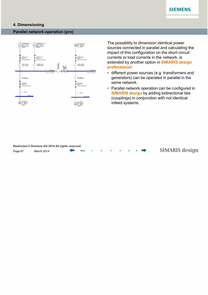
Parallel network operation (pro)
The possibility to dimension identical power
sources connected in parallel and calculating the
impact of this configuration on the short-circuit
currents or load currents in the network, is
extended by another option in SIMARIS design
professional:
• different power sources (e.g. transformers and
generators) can be operated in parallel in thesame network.
• Parallel network operation can be configured in
SIMARIS design by adding bidirectional ties
(couplings) in conjunction with not identical
infeed systems.
4. Dimensioning

8/19/2019 Tutorial SIMARIS Design 8 En
http://slidepdf.com/reader/full/tutorial-simaris-design-8-en 98/114
Restricted © Siemens AG 2014 All rights reserved.
March 2014Page 98 SIMARIS design1 2 3 4 5 6Start
Parallel network operation (pro)
• In the following example, the 4th defined
operating mode (red frame) represents such
parallel network operation.
4. Dimensioning
8/19/2019 Tutorial SIMARIS Design 8 En
http://slidepdf.com/reader/full/tutorial-simaris-design-8-en 99/114
Restricted © Siemens AG 2014 All rights reserved.
March 2014Page 99 SIMARIS design1 2 3 4 5 6Start
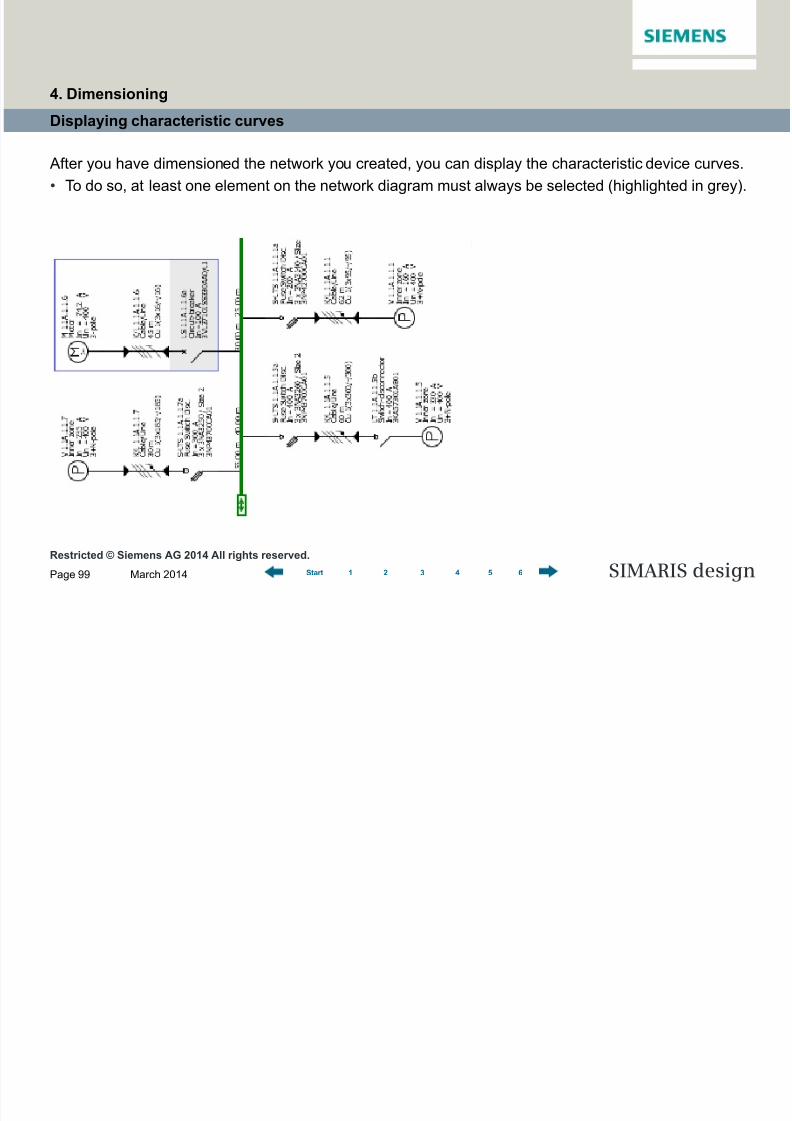
Displaying characteristic curves
After you have dimensioned the network you created, you can display the characteristic device curves.
• To do so, at least one element on the network diagram must always be selected (highlighted in grey).
4. Dimensioning
8/19/2019 Tutorial SIMARIS Design 8 En
http://slidepdf.com/reader/full/tutorial-simaris-design-8-en 100/114
Restricted © Siemens AG 2014 All rights reserved.
March 2014Page 100 SIMARIS design1 2 3 4 5 6Start
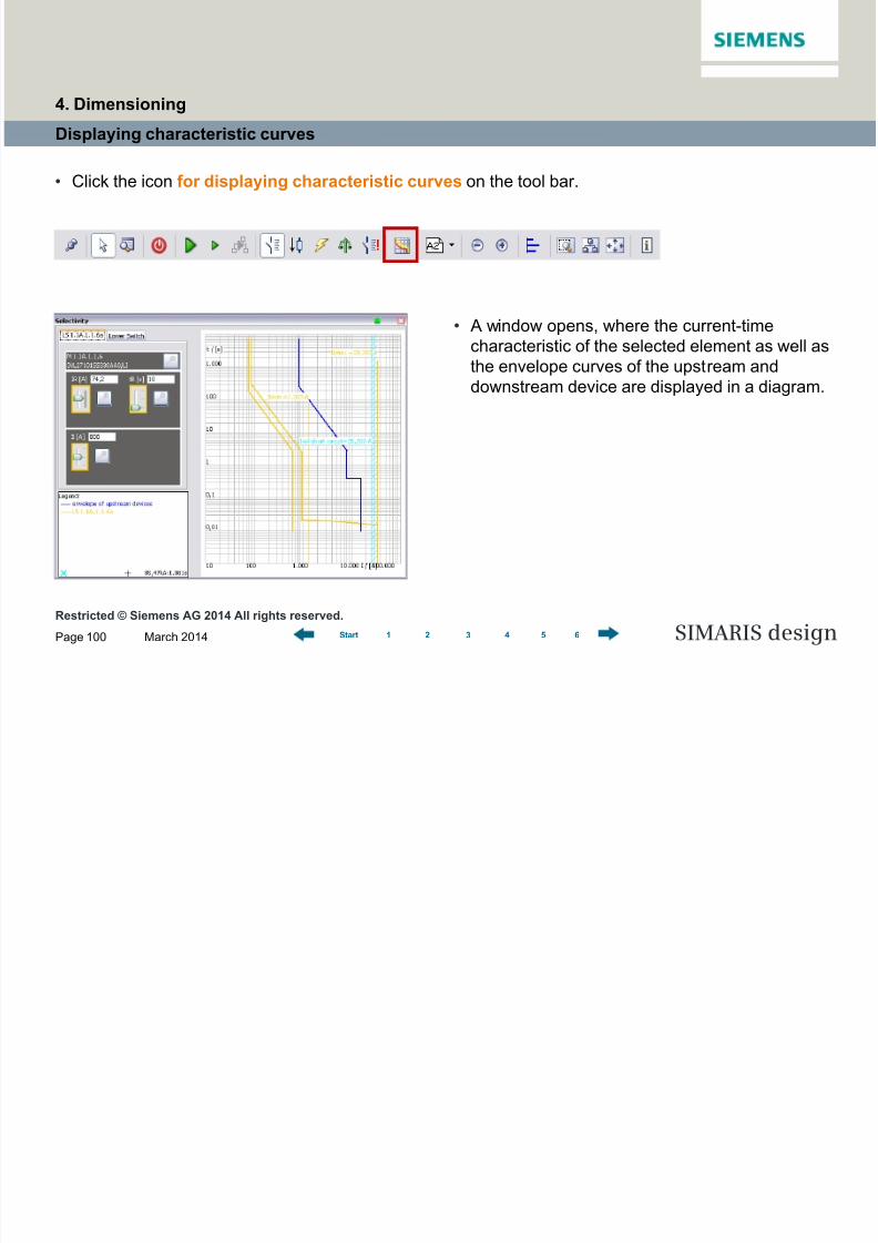
Displaying characteristic curves
• Click the icon for displaying characteristic curves on the tool bar.
• A window opens, where the current-timecharacteristic of the selected element as well as
the envelope curves of the upstream and
downstream device are displayed in a diagram.
4. Dimensioning

8/19/2019 Tutorial SIMARIS Design 8 En
http://slidepdf.com/reader/full/tutorial-simaris-design-8-en 101/114
Restricted © Siemens AG 2014 All rights reserved.
March 2014Page 101 SIMARIS design1 2 3 4 5 6Start
Displaying characteristic curves
• If there is the option for entering parameters of
the selected device, they can now be set with
sliders.
• The effects of these new settings on the current-
time characteristic are simultaneously shown in
the diagram on the right, where the device curve
is adjusted accordingly.
• A click on the key icon of one or all switcheslocks your settings.
• They won't be changed any more in any
subsequent redimensioning process.
• Such devices are identified by a key on the
network diagram as well.
• Any conflicts resulting from the defined setting
are indicated in form of messages below the
network diagram.
4. Dimensioning

8/19/2019 Tutorial SIMARIS Design 8 En
http://slidepdf.com/reader/full/tutorial-simaris-design-8-en 102/114
Restricted © Siemens AG 2014 All rights reserved.
March 2014Page 102 SIMARIS design1 2 3 4 5 6Start
Displaying characteristic curves
• Diagram output with characteristic curves
Program step "Project output"
4. Dimensioning
8/19/2019 Tutorial SIMARIS Design 8 En
http://slidepdf.com/reader/full/tutorial-simaris-design-8-en 103/114
Restricted © Siemens AG 2014 All rights reserved.
March 2014Page 103 SIMARIS design1 2 3 4 5 6Start
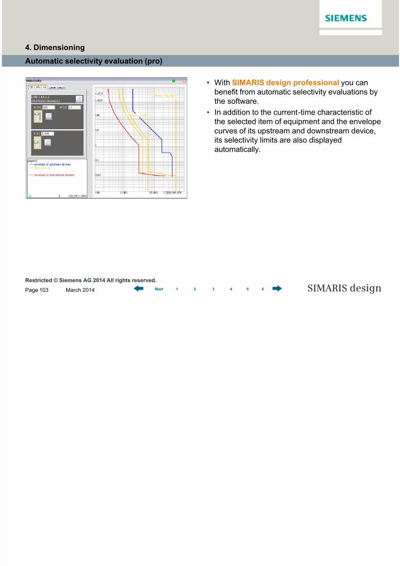
Automatic selectivity evaluation (pro)
• With SIMARIS design professional you can
benefit from automatic selectivity evaluations by
the software.
• In addition to the current-time characteristic of
the selected item of equipment and the envelope
curves of its upstream and downstream device,
its selectivity limits are also displayed
automatically.
4. Dimensioning

8/19/2019 Tutorial SIMARIS Design 8 En
http://slidepdf.com/reader/full/tutorial-simaris-design-8-en 104/114
Restricted © Siemens AG 2014 All rights reserved.
March 2014Page 104 SIMARIS design1 2 3 4 5 6Start
Automatic selectivity evaluation (pro)
• In addition, each switching device is colour-
marked in the entire network diagram as follows,
when selectivity evaluation was enabled:
Green: item is fully selective
Yellow: item is partially selective
Grey: item cannot be evaluated
4. Dimensioning

8/19/2019 Tutorial SIMARIS Design 8 En
http://slidepdf.com/reader/full/tutorial-simaris-design-8-en 105/114
Page 105
Software for efficient dimensioningof power distribution systems
SIMARIS design
SIMARIS design Tutorial
1 Introduction
2 Getting Started
3 Network Design
4 Dimensioning
5 Project Output
6 More about SIMARIS
1 2 3 4 5 6Start
5 Project Output
Overview
Project documentation
Selectivity documentation
Transfer file

8/19/2019 Tutorial SIMARIS Design 8 En
http://slidepdf.com/reader/full/tutorial-simaris-design-8-en 106/114
Restricted © Siemens AG 2014 All rights reserved.
March 2014Page 106 SIMARIS design1 2 3 4 5 6Start
Overview
• In the step "Project output",
you can see the network
diagram you designed on the
right. It cannot be modified
any more in this program step.
5. Project Output
Overview of project output options

8/19/2019 Tutorial SIMARIS Design 8 En
http://slidepdf.com/reader/full/tutorial-simaris-design-8-en 107/114
Restricted © Siemens AG 2014 All rights reserved.
March 2014Page 107 SIMARIS design1 2 3 4 5 6Start
Overview
• In the screen area on the left, you can define the
output type of your project by clicking the
appropriate check box. Below you can select the
options linked to that output type.
5. Project Output
8/19/2019 Tutorial SIMARIS Design 8 En
http://slidepdf.com/reader/full/tutorial-simaris-design-8-en 108/114
Restricted © Siemens AG 2014 All rights reserved.
March 2014Page 108 SIMARIS design1 2 3 4 5 6Start
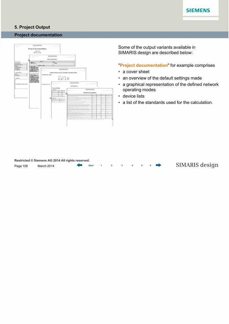
Project documentation
Some of the output variants available in
SIMARIS design are described below:
"Project documentation" for example comprises
• a cover sheet
• an overview of the default settings made
•a graphical representation of the defined networkoperating modes
• device lists
• a list of the standards used for the calculation.
5. Project Output
8/19/2019 Tutorial SIMARIS Design 8 En
http://slidepdf.com/reader/full/tutorial-simaris-design-8-en 109/114
Restricted © Siemens AG 2014 All rights reserved.
March 2014Page 109 SIMARIS design1 2 3 4 5 6Start
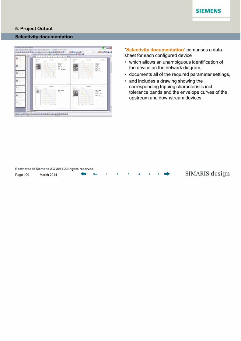
Selectivity documentation
"Selectivity documentation" comprises a data
sheet for each configured device
• which allows an unambiguous identification of
the device on the network diagram,
• documents all of the required parameter settings,
• and includes a drawing showing the
corresponding tripping characteristic incl.
tolerance bands and the envelope curves of the
upstream and downstream devices.
5. Project Output

8/19/2019 Tutorial SIMARIS Design 8 En
http://slidepdf.com/reader/full/tutorial-simaris-design-8-en 110/114
Restricted © Siemens AG 2014 All rights reserved.
March 2014Page 110 SIMARIS design1 2 3 4 5 6Start
Selectivity documentation (professional)
• In addition, users of the professional version
are provided with a selectivity evaluation of
every device and the selectivity limits for the
device are shown on the graphics.
5. Project Output

8/19/2019 Tutorial SIMARIS Design 8 En
http://slidepdf.com/reader/full/tutorial-simaris-design-8-en 111/114
Restricted © Siemens AG 2014 All rights reserved.
March 2014Page 111 SIMARIS design1 2 3 4 5 6Start
Transfer file for SIMARIS project (professional)
• In SIMARIS design professional users are also able to create a transfer file (.sx) to hand over project
data to SIMARIS project *.
* SIMARIS project is a software tool for determining the space requirements of electric power distribution systems and
budgeting them. In addition, it can automatically create tender specification texts for the configured switchgear.
SIMARIS project is currently available for the following countries: Germany, Austria, Switzerland, Poland.
5. Project Output

8/19/2019 Tutorial SIMARIS Design 8 En
http://slidepdf.com/reader/full/tutorial-simaris-design-8-en 112/114
Page 112
Software for efficient dimensioningof power distribution systems
SIMARIS design
SIMARIS design Tutorial
1 Introduction
2 Getting Started
3 Network Design
4 Dimensioning
5 Project Output
6 More about SIMARIS
1 2 3 4 5 6Start
6 More about SIMARIS

8/19/2019 Tutorial SIMARIS Design 8 En
http://slidepdf.com/reader/full/tutorial-simaris-design-8-en 113/114
Restricted © Siemens AG 2014 All rights reserved.
March 2014Page 113 SIMARIS design1 2 3 4 5 6Start
In the SIMARIS design software, you will find more useful information about how to familiarize with the
program and how to handle it efficiently. Click the menu item "Help" to access
• the Help file
• the Technical Manual for SIMARIS design and SIMARIS project.
More information about SIMARIS design and the other tools of the SIMARIS family…
• SIMARIS project for determining the space requirements of distribution boards and the budget, and
for generating specifications (bills of quantities)
• SIMARIS curves for displaying characteristic device curves and visualising parameter settings
can be found at: www.siemens.com/simaris
This website offers you a lot more information and interesting news about the SIMARIS planning tools as
well as the contact data for your local point of contact.
6. More about SIMARIS
8/19/2019 Tutorial SIMARIS Design 8 En
http://slidepdf.com/reader/full/tutorial-simaris-design-8-en 114/114
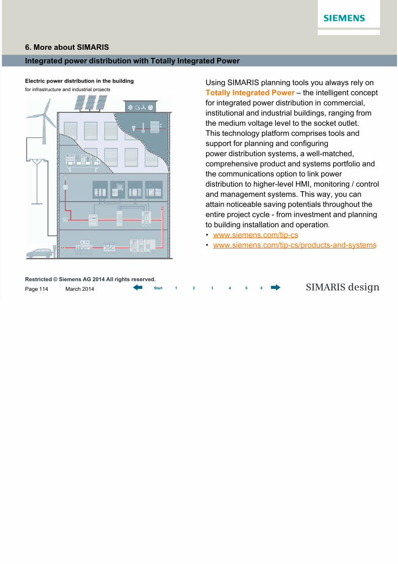
Integrated power distribution with Totally Integrated Power
Using SIMARIS planning tools you always rely on
Totally Integrated Power – the intelligent concept
for integrated power distribution in commercial,
institutional and industrial buildings, ranging from
the medium voltage level to the socket outlet.
This technology platform comprises tools and
support for planning and configuring
power distribution systems, a well-matched,
comprehensive product and systems portfolio and
the communications option to link power
distribution to higher-level HMI, monitoring / control
and management systems. This way, you can
attain noticeable saving potentials throughout the
entire project cycle - from investment and planningto building installation and operation.
• www.siemens.com/tip-cs
• www.siemens.com/tip-cs/products-and-systems
Electric power distribution in the building
for infrastructure and industrial projects
6. More about SIMARIS