Tutorial: Operating with a GPS Unit - · PDF filepage 2 Operating with a GPS Unit Before...
16
Operating with a GPS Unit in TNTmips ® TNTedit ™ TNTview ® G P S Tutorial
Transcript of Tutorial: Operating with a GPS Unit - · PDF filepage 2 Operating with a GPS Unit Before...

Operating witha GPS Unit
in
TNTmips®
TNTedit™
TNTview®
GPS
Tutorial

page 2
Operating with a GPS Unit
Before Getting Started
It may be difficult to identify the important points in some illustrations withouta color copy of this booklet. You can print or read this booklet in color fromMicroImages’ Web site. The Web site is also your source for the newesttutorial booklets on other topics. You can download an installation guide,sample data, and the latest version of TNTlite:
http://www.microimages.com
This booklet introduces techniques for using input from Global Positioning Sys-tem (GPS) receivers in TNTmips®, TNTedit®, and TNTview®. Single GPS coor-dinates can be used to locate discrete features and as control points togeoreference project materials. Streaming GPS coordinates can be used to traceroutes and boundaries. The TNT products let you use direct input from GPSdevices, or use GPS log files that contain GPS output collected previously.
Prerequisite Skills This booklet assumes that you have completed the exercisesin the tutorials Displaying Geospatial Data and Navigation. The exercises inthose booklets present basic skills and techniques that are not covered againhere. Please consult those booklets for any review you need. You should also befamiliar with the concepts of map coordinates and georeference control, whichare part of the study in the tutorial booklet Georeferencing.
Sample Data The exercises presented in this booklet use sample data that isdistributed with the TNT products. If you do not have access to a TNT prod-ucts CD, you can download the data from MicroImages’ Web site. In particu-lar, this booklet uses objects in the GPS data collection. The TNT productsinstallation process makes a read-write copy of these files on your hard drive;you may encounter problems if you work directly with the read-only sample dataon the CD-ROM.
More Documentation This booklet is intended only as an introduction to usingGPS. Consult the TNT Reference Manual for more information.
TNTmips and TNTlite™ TNTmips comes in two versions: the professionalversion and the free TNTlite version. This booklet refers to both versions as“TNTmips.” If you did not purchase the professional version (which requiresa software authorization key), TNTmips operates in TNTlite mode, which lim-its object size.
Support for GPS input is available in TNTmips, TNTedit, and TNTview. All theexercises can be completed in TNTlite using the sample geodata.
Keith Ghormley, 30 April 2005
page 3
Operating with a GPS Unit
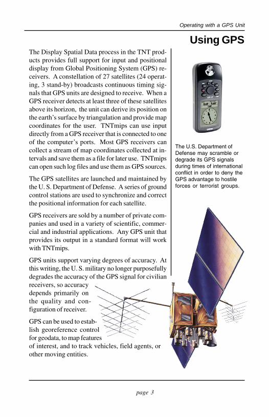
Using GPSThe Display Spatial Data process in the TNT prod-ucts provides full support for input and positionaldisplay from Global Positioning System (GPS) re-ceivers. A constellation of 27 satellites (24 operat-ing, 3 stand-by) broadcasts continuous timing sig-nals that GPS units are designed to receive. When aGPS receiver detects at least three of these satellitesabove its horizon, the unit can derive its position onthe earth’s surface by triangulation and provide mapcoordinates for the user. TNTmips can use inputdirectly from a GPS receiver that is connected to oneof the computer’s ports. Most GPS receivers cancollect a stream of map coordinates collected at in-tervals and save them as a file for later use. TNTmipscan open such log files and use them as GPS sources.
The GPS satellites are launched and maintained bythe U. S. Department of Defense. A series of groundcontrol stations are used to synchronize and correctthe positional information for each satellite.
GPS receivers are sold by a number of private com-panies and used in a variety of scientific, commer-cial and industrial applications. Any GPS unit thatprovides its output in a standard format will workwith TNTmips.
GPS units support varying degrees of accuracy. Atthis writing, the U. S. military no longer purposefullydegrades the accuracy of the GPS signal for civilianreceivers, so accuracydepends primarily onthe quality and con-figuration of receiver.
GPS can be used to estab-lish georeference controlfor geodata, to map featuresof interest, and to track vehicles, field agents, orother moving entities.
The U.S. Department ofDefense may scramble ordegrade its GPS signalsduring times of internationalconflict in order to deny theGPS advantage to hostileforces or terrorist groups.
page 4
Operating with a GPS Unit
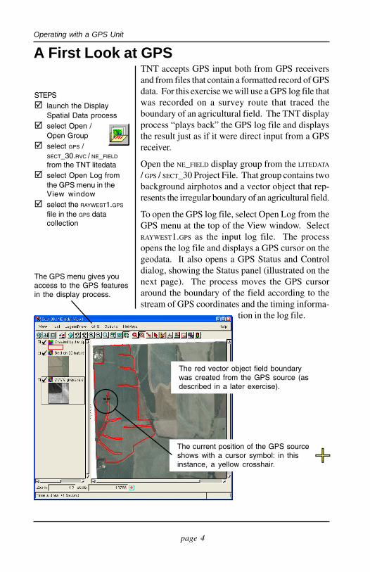
A First Look at GPSTNT accepts GPS input both from GPS receiversand from files that contain a formatted record of GPSdata. For this exercise we will use a GPS log file thatwas recorded on a survey route that traced theboundary of an agricultural field. The TNT displayprocess “plays back” the GPS log file and displaysthe result just as if it were direct input from a GPSreceiver.
Open the NE_FIELD display group from the LITEDATA
/ GPS / SECT_30 Project File. That group contains twobackground airphotos and a vector object that rep-resents the irregular boundary of an agricultural field.
To open the GPS log file, select Open Log from theGPS menu at the top of the View window. SelectRAYWEST1.GPS as the input log file. The processopens the log file and displays a GPS cursor on thegeodata. It also opens a GPS Status and Controldialog, showing the Status panel (illustrated on thenext page). The process moves the GPS cursoraround the boundary of the field according to thestream of GPS coordinates and the timing informa-
tion in the log file.
STEPS launch the Display
Spatial Data process select Open /
Open Group select GPS /
SECT_30.RVC / NE_FIELD
from the TNT litedata select Open Log from
the GPS menu in theView window
select the RAYWEST1.GPS
file in the GPS datacollection
The current position of the GPS sourceshows with a cursor symbol: in thisinstance, a yellow crosshair.
The red vector object field boundarywas created from the GPS source (asdescribed in a later exercise).
The GPS menu gives youaccess to the GPS featuresin the display process.
page 5
Operating with a GPS Unit
Configuring Your GPS DeviceThe TNT products can accept GPS input from GPSreceivers and from log files. In the previous exer-cise, a GPS log file was used to trace the outline ofan agricultural field. In this exercise, you will con-figure your receiver for use with the TNT products.
The first thing to do is to set up your GPS unit ac-cording to the manufacturer’s instructions. Turn iton and make sure it is working correctly before youconnect it to your computer.
After your receiver is on and working correctly, at-tach it to your computer. Commonly, this involvesconnecting a cable from the receiver to one of thecomputer’s serial ports.
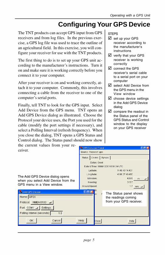
Finally, tell TNT to look for the GPS input. SelectAdd Device from the GPS menu. TNT opens anAdd GPS Device dialog as illustrated. Choose theProtocol your device uses, the Port you used for thecable (modify the port settings if necessary), andselect a Polling Interval (refresh frequency). Whenyou close the dialog, TNT opens a GPS Status andControl dialog. The Status panel should now showthe current values from your re-ceiver.
STEPS set up your GPS
receiver according tothe manufacturer’sinstructions
verify that your GPSreceiver is workingcorrectly
connect the GPSreceiver’s serial cableto a serial port on yourcomputer
select Add Device fromthe GPS menu in theView window
choose device settingsin the Add GPS Devicedialog
compare the readout inthe Status panel of theGPS Status and Controlwindow to the displayon your GPS receiver
The Add GPS Device dialog openswhen you select Add Device from theGPS menu in a View window.
The Status panel showsthe readings comingfrom your GPS receiver.
page 6
Operating with a GPS Unit
Prerequisite GeoreferenceFor your GPS input to display correctly with yourother project materials, those materials must begeoreferenced. TNT automatically reconciles dif-fering map projections, coordinate systems and da-tums, so you can use a variety of georeference con-trol. Refer to the tutorial booklet Georeferencing.
Three factors affect the accuracy you will get fromusing GPS receivers. First, the accuracy of yourGPS receiver. If your GPS input is accurate to 30meters, then you will notice some mis-registration ifyour reference materials have 3 meter accuracy.
The second factor is the accuracy of yourgeoreference control. The cell size of your refer-ence imagery may be 3 meters, but if yourgeoreference control is taken from reference sourcesthat have only 70-meter accuracy, then your GPS
mis-registration difficulties willcompound.
The third factor is the accuracy ofyour project materials. You mayhave 1 meter GPS accuracy, but ifyour reference imagery is 30-metersatellite data, then the GPS accu-racy will not show in the display.
In sum, a casual approach togeoreferencing can result in un-wanted difficulties and reducedusefulness of GPS input. Be surethat the use you intend to make ofyour project materials is supportedby the accuracy of yourgeoreference control.
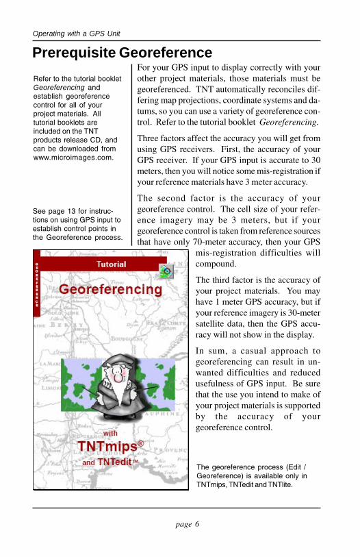
Refer to the tutorial bookletGeoreferencing andestablish georeferencecontrol for all of yourproject materials. Alltutorial booklets areincluded on the TNTproducts release CD, andcan be downloaded fromwww.microimages.com.
The georeference process (Edit /Georeference) is available only inTNTmips, TNTedit and TNTlite.
See page 13 for instruc-tions on using GPS input toestablish control points inthe Georeference process.

page 7
Operating with a GPS Unit
GPS Cursor ModesThe GPS cursor in the View window automaticallyswitches between three cursor modes: Moving,Stopped, and Out-of-View.
The Out-of-View cursor (illustrated below) alwaysappears along the edge of a View closest to the GPSlocation and points towards the source. If the GPSsource moves into the extents of the view, then thecursor automatically changes to the Moving cursorsymbol. The Out-of-View cursor symbol cannot bechanged.
The Moving and Stopped cursor symbols can beselected from any existing point symbol or createdwith the symbol editor. Refer to the companion tu-torial booklet Creating and Using Styles.
For this exercise, change the Moving symbol. Se-lect the Symbol panel in the GPS Status and Controldialog. Click the Styles button and open the SECT_30/ GPSSTYLES object. Select Moving from the SymbolFor option button. Select PointSymbol from the Point Type:option button. Select the planesymbol and choose a color andsize for it.
As soon as you choose a sym-bol, it appears in the View win-dow. Since the GPS Status andControl dialog stays open whilethe GPS source is active, youdo not close the dialog to ap-ply style changes.
STEPS keep the RAYWEST1.GPS
log file open and playing(see page 4)
select the Symbol tab inthe GPS Status andControl dialog
click the Styles... buttonand select the GPS /SECT_30 / GPSSTYLES
object select Moving from the
Symbol For optionbutton
select Point Symbolfrom the Point Typeoption button
choose the PLANE pointsymbol
The out-of-viewcursor appearswhenever the GPS
source is beyond the extents ofthe geodata in the group.
The Symbol panel lets youchoose separate pointsymbols for Moving andStopped cursor modes.
page 8
Operating with a GPS Unit
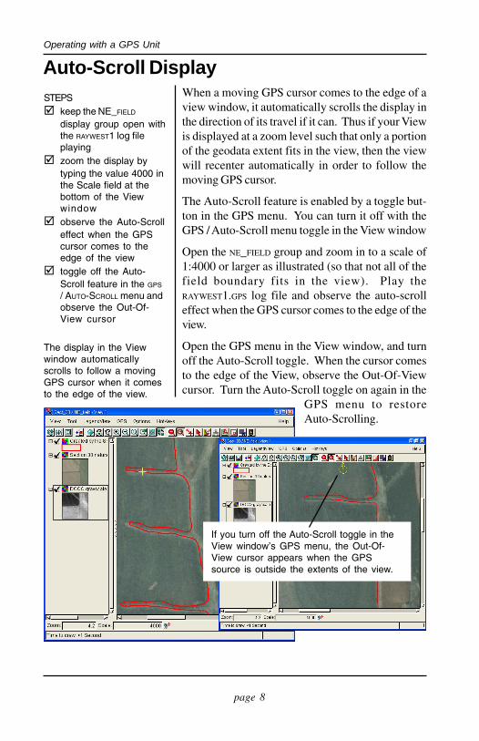
Auto-Scroll DisplayWhen a moving GPS cursor comes to the edge of aview window, it automatically scrolls the display inthe direction of its travel if it can. Thus if your Viewis displayed at a zoom level such that only a portionof the geodata extent fits in the view, then the viewwill recenter automatically in order to follow themoving GPS cursor.
The Auto-Scroll feature is enabled by a toggle but-ton in the GPS menu. You can turn it off with theGPS / Auto-Scroll menu toggle in the View window
Open the NE_FIELD group and zoom in to a scale of1:4000 or larger as illustrated (so that not all of thefield boundary fits in the view). Play theRAYWEST1.GPS log file and observe the auto-scrolleffect when the GPS cursor comes to the edge of theview.
Open the GPS menu in the View window, and turnoff the Auto-Scroll toggle. When the cursor comesto the edge of the View, observe the Out-Of-Viewcursor. Turn the Auto-Scroll toggle on again in the
GPS menu to restoreAuto-Scrolling.
STEPS keep the NE_FIELD
display group open withthe RAYWEST1 log fileplaying
zoom the display bytyping the value 4000 inthe Scale field at thebottom of the Viewwindow
observe the Auto-Scrolleffect when the GPScursor comes to theedge of the view
toggle off the Auto-Scroll feature in the GPS
/ AUTO-SCROLL menu andobserve the Out-Of-View cursor
If you turn off the Auto-Scroll toggle in theView window’s GPS menu, the Out-Of-View cursor appears when the GPSsource is outside the extents of the view.
The display in the Viewwindow automaticallyscrolls to follow a movingGPS cursor when it comesto the edge of the view.

page 9
Operating with a GPS Unit
Directional Cursor SymbolsThe GPS cursor can be chosen from symbols thatshow travel direction. Thus, A vehicle, airplane, orarrow symbol can be selected for the moving cursormode, and the symbol dynamically orients itself topoint in the direction of travel. The plane symbolyou selected on page 7 shows travel direction.
TNT interpolates the travel direction from the streamof recent points. If the recent points are very closetogether, the cursor may occasionally show erraticorientation.
Your style object may contain a symbol importedfrom TrueType character whose orientation is in-correct. That is, TNT sets the orientation of a direc-tional cursor symbol in reference to the symbol’sbase point defined in the TNT Symbol Editor. If youneed to establish or change the orientation of a di-rectional cursor symbol, edit the symbol in the TNTSymbol Editor (Edit / Styles).
You define the orientationof a symbol in the TNTSymbol Editor by placing theOrigin point at the base (tailend) of the symbol. Referto the tutorial Creating andUsing Styles.
STEPS use the NE_FIELD group
and the RAYWEST1.GPS
source click the Styles... button
in the Symbol panel ofthe GPS Status andControl dialog
select the SECT_30.RVC /GPSSTYLES style object
select Moving from theSymbol For optionbutton
change Point Type: toPoint Symbol
select the FOCUS symbol
The Moving GPS cursor symbol can beselected from symbols that show adirection of travel. The cursor adjusts itsorientation dynamically according to inputfrom the GPS source.
Change theinitial orientationof a symbolwith the Angle:value.
page 10
Operating with a GPS Unit
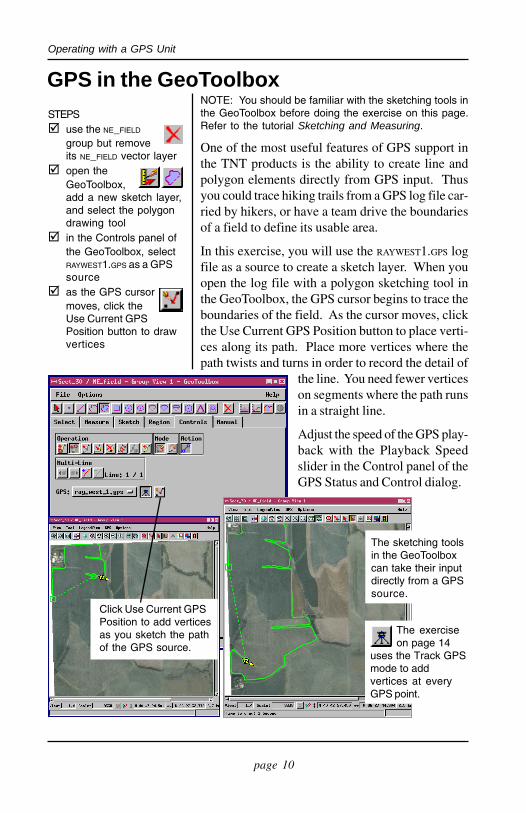
GPS in the GeoToolboxNOTE: You should be familiar with the sketching tools inthe GeoToolbox before doing the exercise on this page.Refer to the tutorial Sketching and Measuring.
One of the most useful features of GPS support inthe TNT products is the ability to create line andpolygon elements directly from GPS input. Thusyou could trace hiking trails from a GPS log file car-ried by hikers, or have a team drive the boundariesof a field to define its usable area.
In this exercise, you will use the RAYWEST1.GPS logfile as a source to create a sketch layer. When youopen the log file with a polygon sketching tool inthe GeoToolbox, the GPS cursor begins to trace theboundaries of the field. As the cursor moves, clickthe Use Current GPS Position button to place verti-ces along its path. Place more vertices where thepath twists and turns in order to record the detail of
the line. You need fewer verticeson segments where the path runsin a straight line.
Adjust the speed of the GPS play-back with the Playback Speedslider in the Control panel of theGPS Status and Control dialog.
STEPS use the NE_FIELD
group but removeits NE_FIELD vector layer
open theGeoToolbox,add a new sketch layer,and select the polygondrawing tool
in the Controls panel ofthe GeoToolbox, selectRAYWEST1.GPS as a GPSsource
as the GPS cursormoves, click theUse Current GPSPosition button to drawvertices
Click Use Current GPSPosition to add verticesas you sketch the pathof the GPS source.
The sketching toolsin the GeoToolboxcan take their inputdirectly from a GPSsource.
The exerciseon page 14
uses the Track GPSmode to addvertices at everyGPS point.
page 11
Operating with a GPS Unit
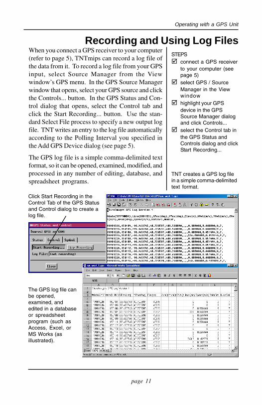
Recording and Using Log FilesWhen you connect a GPS receiver to your computer(refer to page 5), TNTmips can record a log file ofthe data from it. To record a log file from your GPSinput, select Source Manager from the Viewwindow’s GPS menu. In the GPS Source Managerwindow that opens, select your GPS source and clickthe Controls... button. In the GPS Status and Con-trol dialog that opens, select the Control tab andclick the Start Recording... button. Use the stan-dard Select File process to specify a new output logfile. TNT writes an entry to the log file automaticallyaccording to the Polling Interval you specified inthe Add GPS Device dialog (see page 5).
The GPS log file is a simple comma-delimited textformat, so it can be opened, examined, modified, andprocessed in any number of editing, database, andspreadsheet programs.
The GPS log file canbe opened,examined, andedited in a databaseor spreadsheetprogram (such asAccess, Excel, orMS Works (asillustrated).
TNT creates a GPS log filein a simple comma-delimitedtext format.
Click Start Recording in theControl Tab of the GPS Statusand Control dialog to create alog file.
STEPS connect a GPS receiver
to your computer (seepage 5)
select GPS / SourceManager in the Viewwindow
highlight your GPSdevice in the GPSSource Manager dialogand click Controls...
select the Control tab inthe GPS Status andControls dialog and clickStart Recording...

page 12
Operating with a GPS Unit
Multiple Inputs: The Source Manager
STEPS open a view with the
raster object GPS /OTOE.RVC / OTOE
use the Open Logselection on the Viewwindow’s GPS menu toadd SOUTH.GPS, HOME.GPS,and NORTH.GPS in turn
use the GPS Status andControl dialog for eachlog file to selectdifferent symbols andcolors for each source
Since most desktop computers provide only a coupleof serial ports that can be used for connecting GPSreceivers, configuring your hardware for multiplesimultaneous GPS inputs is not a trivial exercise.That is, you can easily watch a truck or two, butwithout a customized configuration, you won’t seeevery vehicle in the fleet in real time. You are morelikely to use the multiple-source capability of theTNT products to play back multiple log files. Prop-erly synchronized, multiple inputs can offer a strongtool for visualization and analysis.
To synchronize GPS inputs from multiple log files,use their GPS Status and Control dialogs. Pauseeach GPS cursor at the starting point you want withthe playback buttons in the Control tab. When youhave each GPS input paused at the “starting point”you want for it, click the Play button in the Controlstab to start them.
Use the GPS Source Managerto open and manage multiplelog files and GPS devicessimultaneously.
Left: Three GPS log files playsimultaneously in the Viewwindow. Each input has beenassigned a different cursorsymbol.

page 13
Operating with a GPS Unit
GPS in the Georeference ProcessGPS receivers provide an excellent way to collectprecise control points for georeferencing yourproject materials. Thus, if you have an airphoto togeoreference, you could visit the site with a GPSunit, and record map coordinates for several well-distributed features that show in the image. In thisscenario, you would simply make a list of featuresand their coordinates in a notebook, and enter thecoordinates in the georeference process when youreturn to your desk.
Another method would be to take a portable com-puter to the site and use your GPS device for directinput. Since GPS input is enabled only for viewsthat have some existing georeference, you need somekind of initial reference object. One approach wouldbe to draw a simple rectangle in TNT’s GeospatialEditor, and assign its corners to map coordinates sothat your airphoto site is contained within it. Thenyou can load that “frame” object in the field to es-tablish your general geospatial location, and useyour GPS input to drop vertices in a new sketchobject. Back at your desk, you can use your sketchas a reference object in the georeference process.
Create a “frame” objectand assign map coordi-nates to its corners suchyour airphoto is containedwithin it.
In the field, use GPS inputover the frame to create asketch object that containsfeatures visible in theairphoto.
Use the sketch as yourreference object in the TNTgeoreference process.
Refer to theGeoreferencing tutorial andestablish georeferencecontrol for all of yourproject materials. All tutorialbooklets are included on theTNT products release CD,and can be downloadedfromwww.microimages.com.
The sketching tools in theGeoToolbox can take theirinput directly from a GPSsource. Refer to page 10for information about usingGPS input to create asketch object.

page 14
Operating with a GPS Unit
GPS in the Geospatial EditorUsing GPS input in the editor is similar to using GPSinput for sketch objects in the display process (seepage 10). You will choose to use the editor insteadof the sketch tool when you want to work on morecomplex combinations of geodata. The editor letsyou have several objects of different types openfor editing simultaneously, and it provides featuresthat the sketch tool does not.
As it draws a line or polygon, the editor can addvertices in two ways: it can add a vertex at everyGPS point, or it can add a vertex only when you tellit to. In the sketch exercise on page 10, you usedthe Use Current GPS button to add vertices explic-itly. For this exercise, use the Track GPS button sothat every point in the GPS log is used as a vertex inthe new polygon element.
If you are not familiar with the geospatial editor,refer to the tutorial Editing Vector Geodata for moreinformation.
Turn off the Auto-Repeattoggle in the Control panel ofthe GPS Status and Controlwindow and wait for theGPS playback to finish.Then add the whole polygonat once.
STEPS launch the Edit / Spatial
Data process
add a referencelayer with theraster object GPS /OTOE.RVC / OTOE
create a newvector object
use the Open Logselection on the Viewwindow’s GPS menu toadd HOME.GPS
select the editor’sAdd Polygon tool
select the HOME.GPS
source and theTrack GPS mode in theLine/Polygon EditControls
when the playback iscomplete, add thepolygon
Use the Track GPSbutton to get a vertexat every GPS point.
Select theHOME.GPS
source.
page 15
Operating with a GPS Unit
GPS in SML and APPLIDATsSupport for GPS devices is found throughout all theprocesses of TNTmips. You can use the GPS tech-niques introduced in this booklet in any processthat has a view window. For example, you can useGPS input or log files in the Feature Mapping pro-cess (Process / Raster / Interpret / Feature Map) tocheck the classifications you make against groundtruth that is coordinated with GPS points.
GPS input can also be manipulated in custom pro-cesses that you develop with TNTsdk or with thegeospatial scripting language (SML). All the func-tions you need for polling and reading GPS inputsare found in the functions and libraries provided.
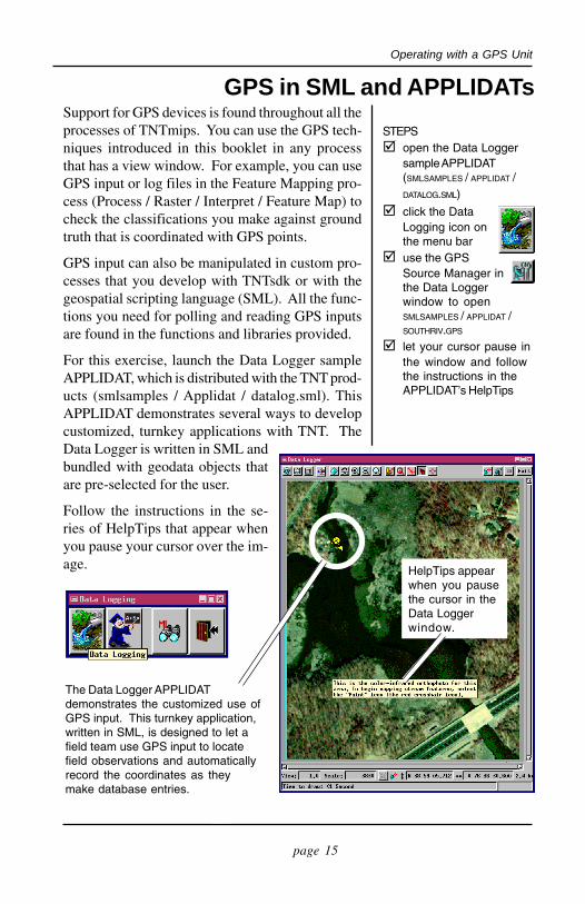
For this exercise, launch the Data Logger sampleAPPLIDAT, which is distributed with the TNT prod-ucts (smlsamples / Applidat / datalog.sml). ThisAPPLIDAT demonstrates several ways to developcustomized, turnkey applications with TNT. TheData Logger is written in SML andbundled with geodata objects thatare pre-selected for the user.
Follow the instructions in the se-ries of HelpTips that appear whenyou pause your cursor over the im-age.
The Data Logger APPLIDATdemonstrates the customized use ofGPS input. This turnkey application,written in SML, is designed to let afield team use GPS input to locatefield observations and automaticallyrecord the coordinates as theymake database entries.
STEPS open the Data Logger
sample APPLIDAT(SMLSAMPLES / APPLIDAT /DATALOG.SML)
click the DataLogging icon onthe menu bar
use the GPSSource Manager inthe Data Loggerwindow to openSMLSAMPLES / APPLIDAT /SOUTHRIV.GPS
let your cursor pause inthe window and followthe instructions in theAPPLIDAT’s HelpTips
HelpTips appearwhen you pausethe cursor in theData Loggerwindow.

MicroImages, Inc.
Advanced Software for Geospatial Analysis GPS
email: [email protected]: www.microimages.com
Voice: (402)477-9554FAX (402) 817-0151
MicroImages, Inc. publishes a complete line of professional software for advancedgeospatial data visualization, analysis, and publishing. Contact us or visit our web site fordetailed product information.
TNTmips TNTmips is a professional system for fully integrated GIS, image analysis,CAD, TIN, desktop cartography, and geospatial database management.
TNTedit TNTedit provides interactive tools to create, georeference, and edit vector, image,CAD, TIN, and relational database project materials in a wide variety of formats.
TNTview TNTview has the same powerful display features as TNTmips and is perfect forthose who do not need the technical processing and preparation features of TNTmips.
TNTatlas TNTatlas lets you publish and distribute your spatial project materials on CD-ROM at low cost. TNTatlas CDs can be used on any popular computing platform.
TNTserver TNTserver lets you publish TNTatlases on the Internet or on your intranet.Navigate through geodata atlases with your web browser and the TNTclient Java applet.
TNTlite TNTlite is a free version of TNTmips for students and professionals with smallprojects. You can download TNTlite from MicroImages’ web site, or you can orderTNTlite on CD-ROM.
accuracy .............................................. 6add GPS device dialog ......................... 5APPLIDATs ..................................... 15auto-scroll ........................................... 8configure receiver ................................ 5cursor modes ....................................... 7DataLogger ........................................ 15directional cursors ............................... 9editor ................................................. 14Feature Mapping .............................. 15georeference .................................. 6, 13geospatial editor ................................ 14GeoToolbox ...................................... 10
Indexlog file ........................................... 4, 11multiple inputs ................................. 12out-of-view ......................................... 7polling interval .............................. 5, 11receivers .............................................. 3recording a log file ............................. 11sample data ......................................... 2signal degradation ................................ 3sketch from GPS input ..................... 10SML .................................................. 15source manager ............................ 11, 12status and control dialog ................. 3, 4status panel ......................................... 5