
Tutorial Oficina de Fisica IFGW 2007 - Portal IFGW · 1 Laser Communications Prof. Hugo L. Fragnito...
55
1 Laser Communications Laser Communications Prof. Hugo L. Fragnito Centro de Pesquisa em Óptica e Fotônica da Unicamp Projeto KyaTera Tel. (xx55-19) 3521-5430 [email protected] UNICAMP-IFGW Instituto de Física Gleb Wataghin, Campinas, 13083-970, SP, Brazil www.kyatera.fapesp.br XX Oficina de Física IFGW, 24 –Nov-2007
Transcript of Tutorial Oficina de Fisica IFGW 2007 - Portal IFGW · 1 Laser Communications Prof. Hugo L. Fragnito...

1
Laser CommunicationsLaser Communications
Prof. Hugo L. Fragnito
Centro de Pesquisa em Óptica e Fotônica da UnicampProjeto KyaTera
Tel. (xx55-19) [email protected]
UNICAMP-IFGWInstituto de Física Gleb Wataghin, Campinas, 13083-970, SP, Brazil
www.kyatera.fapesp.br
XX Oficina de FísicaIFGW, 24 –Nov-2007
2
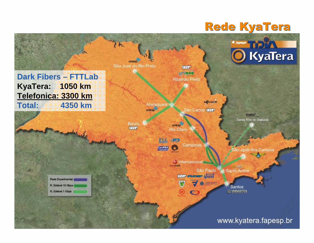
Rede KyaTeraRede KyaTera
Dark Fibers – FTTLabKyaTera: 1050 kmTelefonica: 3300 kmTotal: 4350 km
333 H. Fragnito H. Fragnito H. Fragnito CePOFCePOFCePOF ––– UNICAMPUNICAMPUNICAMP
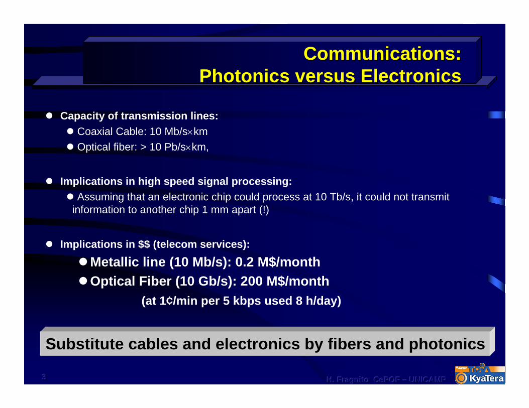
Communications: Communications: Photonics versus ElectronicsPhotonics versus Electronics
Capacity of transmission lines:Coaxial Cable: 10 Mb/s×kmOptical fiber: > 10 Pb/s×km,
Implications in high speed signal processing:Assuming that an electronic chip could process at 10 Tb/s, it could not transmit
information to another chip 1 mm apart (!)
Implications in $$ (telecom services):
Metallic line (10 Mb/s): 0.2 M$/monthOptical Fiber (10 Gb/s): 200 M$/month
(at 1¢/min per 5 kbps used 8 h/day)
Substitute cables and electronics by fibers and photonics

4
System conceptsSystem conceptsElements of transmission systems
MultiplexingModulation Formats
Optically amplified systemsWDM systems

555 H. Fragnito H. Fragnito H. Fragnito CePOFCePOFCePOF ––– UNICAMPUNICAMPUNICAMP
Elements of a Communication SystemElements of a Communication System
Tx
Transmitter
Transmission Line Rx
Receiver
Input Output
Laser + modulator
Optical fiberPhotodiode +Filter + clock recovery + ...
Tx Fiber PairElectrical
Input
RxOutput
Transceiver
RxInputTx
Electrical Output
TransceiverInput
666 H. Fragnito H. Fragnito H. Fragnito CePOFCePOFCePOF ––– UNICAMPUNICAMPUNICAMP
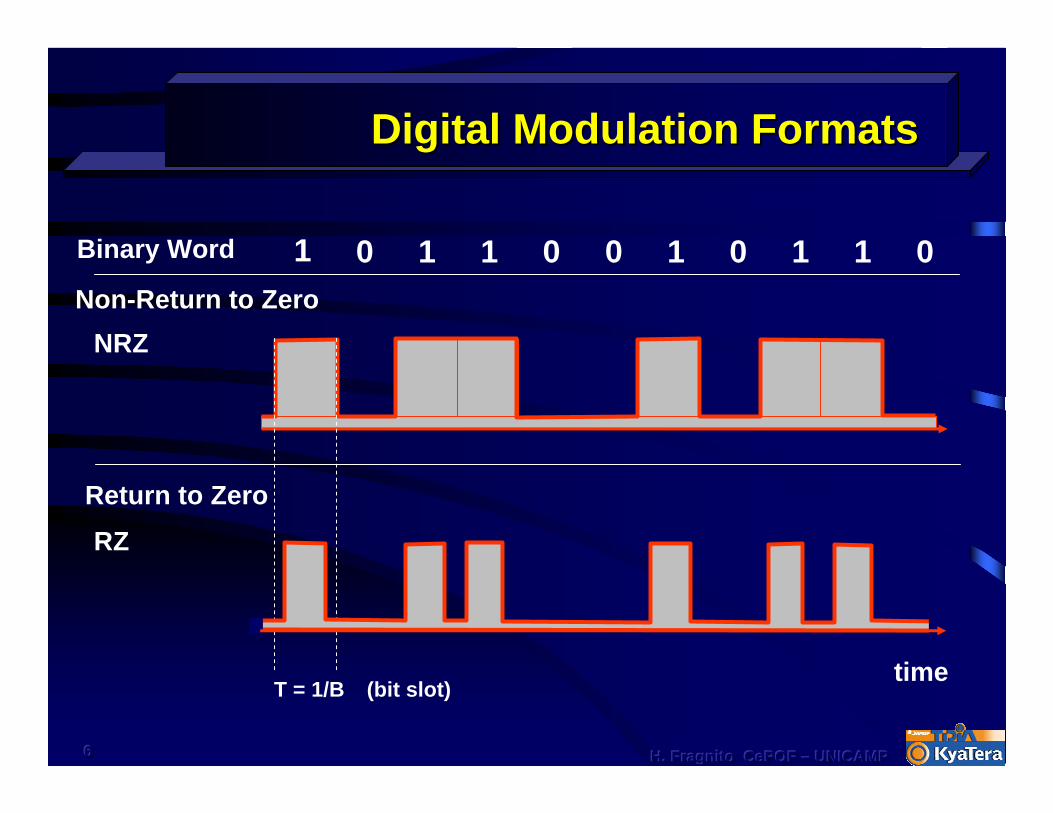
Digital Modulation FormatsDigital Modulation Formats
1 0 1 0 1 1 01 0 0 1
NRZNon-Return to Zero
Binary Word
time(bit slot)T = 1/B
RZ
Return to Zero

777 H. Fragnito H. Fragnito H. Fragnito CePOFCePOFCePOF ––– UNICAMPUNICAMPUNICAMP
Traditional Optical Communication SystemTraditional Optical Communication System
Tx
Timing & Shapingcircuits
Transmitter Repeater
Rx
Receiver
Laser
Optoelectronic repeater
Photodiode
Optical fiber (20-50 km)
Loss compensation: Repeaters at every 20-50 km
Capacity limited by speed of electronic circuits. Timing circuits are specific for a given bit rate, protocol coding, format,…
Capacity limited by speed of electronic circuits. Timing circuits are specific for a given bit rate, protocol coding, format,…
3R
3R = Retiming, Reshaping &Regeneration

888 H. Fragnito H. Fragnito H. Fragnito CePOFCePOFCePOF ––– UNICAMPUNICAMPUNICAMP
Optically Amplified SystemsOptically Amplified Systems
Photodiode
EDFA
Laser
EDFAEDFA EDFA
Signal (1.55 µm)
WDM
Erbium Doped Fiber (10-50 m)Amplified
Signal
Pump Lasers (1.48 µm or 980 nm)
isolatorWDM
Booster Pre-AmpFiber (20-100 km)
Bits continue in photonic format
EDFA = Erbium Doped Fiber Amplifier
Transparent to bit rate (< 4 Tb/s), protocol, format,…
999 H. Fragnito H. Fragnito H. Fragnito CePOFCePOFCePOF ––– UNICAMPUNICAMPUNICAMP
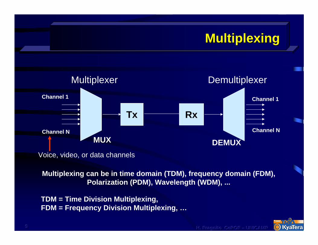
MultiplexingMultiplexing
MultiplexerChannel 1
Channel N
Voice, video, or data channels
Demultiplexer
Channel 1
Channel N
MUX DEMUX
Tx Rx
Multiplexing can be in time domain (TDM), frequency domain (FDM), Polarization (PDM), Wavelength (WDM), ...
TDM = Time Division Multiplexing, FDM = Frequency Division Multiplexing, …

101010 H. Fragnito H. Fragnito H. Fragnito CePOFCePOFCePOF ––– UNICAMPUNICAMPUNICAMP
DWDM SystemsDWDM Systems
Transmitters (Bit rate = B)Optical Amplifiers
λ1
λ2
λN
Receivers
λ1
λ2
λN
MUX
DeM
UX
Pow
erde
nsity
Frequency, ν (THz)192.8 193.0 193.1192.9
∆ν ∆ν = 100 GHz, 50 GHz, (up to 40 Gb/s) DWDM
25 GHz, or 12.5 GHz(up to 10 Gb/s) UDWDM (Ultra Dense)
[100 GHz : 0.8 nm]
DWDM = Dense Wavelength Division MultiplexingDWDM = Dense Wavelength Division Multiplexing
ITU gridνn = ν0 + n∆ν
ν0 = 193.1 THz(1552.52 nm)
(n = 0, ±1, ±2, ...)
CWDM = Coarse WDM:∆λ = 20 nm
Cheaper than DWDM
Some System Components and Some System Components and DevicesDevices
Optical fibersFiber Couplers
Fiber ConnectorsLasers and Detectors
Optical AmplifiersDWDM MUX/DeMUX
Modulators

121212 H. Fragnito H. Fragnito H. Fragnito CePOFCePOFCePOF ––– UNICAMPUNICAMPUNICAMP
Optical FibersOptical Fibers
Optical fibers are cylindrical dielectric waveguidesCore (Ge, Al,.. doped silica)
Cladding (pure silica)
n1 (n1 > n2)2a2b
Typical dimensionsCore diameter 2a = 9 to 62.5 µmCladding diameter 2b = 125 µm
Typical values of refractive indices
Core: n1 = 1.446Cladding: n2 = 1.445
n2

131313 H. Fragnito H. Fragnito H. Fragnito CePOFCePOFCePOF ––– UNICAMPUNICAMPUNICAMP
n1
n2
∆n
Index profileIndex profile
Protection claddingPlastic (250 µm)
Claddingpure silica (125 µm)
CoreDoped silica (9 – 62.5 µm)
Index step typical values:∆n = 0.001 - 0.01
141414 H. Fragnito H. Fragnito H. Fragnito CePOFCePOFCePOF ––– UNICAMPUNICAMPUNICAMP
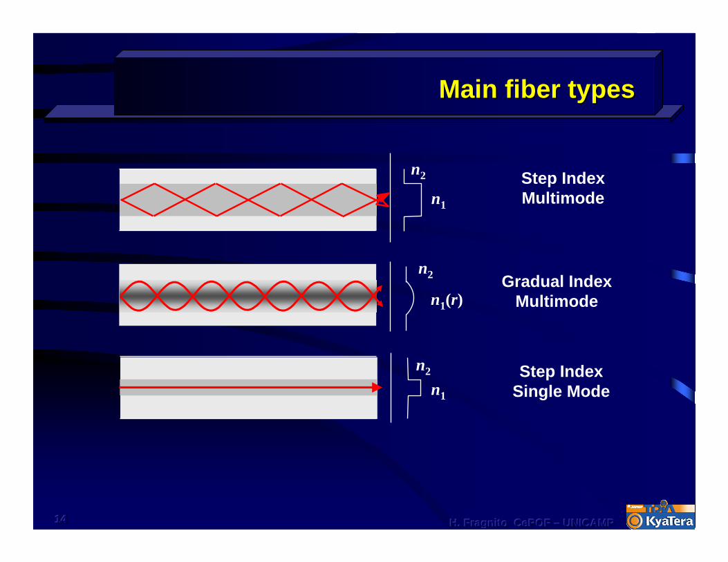
Main fiber typesMain fiber types
Step IndexMultimode
Step IndexSingle Mode
Gradual IndexMultimode
n1
n2
n1
n2
n2
n1(r)

151515 H. Fragnito UNICAMP H. Fragnito UNICAMP H. Fragnito UNICAMP ––– IFGWIFGWIFGWSwiecaSwiecaSwieca 200220022002
Fiber connectorsFiber connectors
• Various Types• FC/PC, SC, LC, SMA, ST
• Polishing quality • SPC (Super), UPC (Ultra)
PC = Physical ContactInsertion loss 0.2 dBBack reflection –20 dB
APC = Angled Physical ContactInsertion loss 0.2 dBBack reflection –40 dB
8°
Fiber
Alumina ferrule

161616 H. Fragnito H. Fragnito H. Fragnito CePOFCePOFCePOF ––– UNICAMPUNICAMPUNICAMP
Optical CablesOptical Cables
Patch cords
171717 H. Fragnito H. Fragnito H. Fragnito CePOFCePOFCePOF ––– UNICAMPUNICAMPUNICAMP
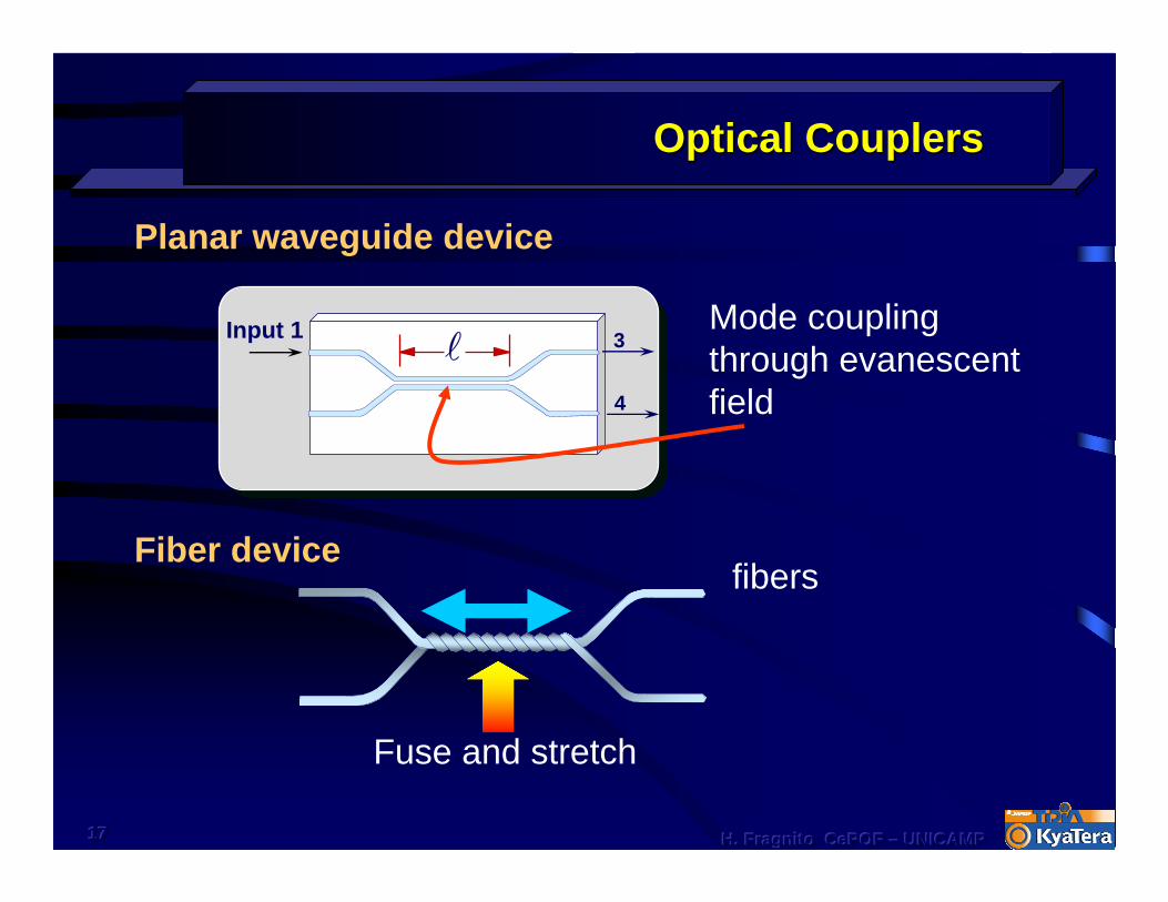
Optical CouplersOptical Couplers
Mode coupling through evanescent field
3
4
Input 1
Planar waveguide device
Fiber device
Fuse and stretch
fibers
18
Attenuationand
Dispersion
Attenuationand
Dispersion

191919 H. Fragnito H. Fragnito H. Fragnito CePOFCePOFCePOF ––– UNICAMPUNICAMPUNICAMP
Decibel unitsDecibel units
System
Input power Output power
Pin Pout
System Transmission: T = Pout/Pin
TdB = 10 log(Pout/Pin) -10 dB means Pout = Pin /10-3 dB means Pout = Pin /2-40 dB means Pout = 10-4 Pin
dBm: Power in dB relative to 1 mW
PdBm = 10 log (P/mW) -10 dBm means P = 0.1 mW3 dBm means P = 2 mW40 dBm means P = 10 W
TdB = Pout - Pin (Pin and Pout in dBm)
202020 H. Fragnito H. Fragnito H. Fragnito CePOFCePOFCePOF ––– UNICAMPUNICAMPUNICAMP
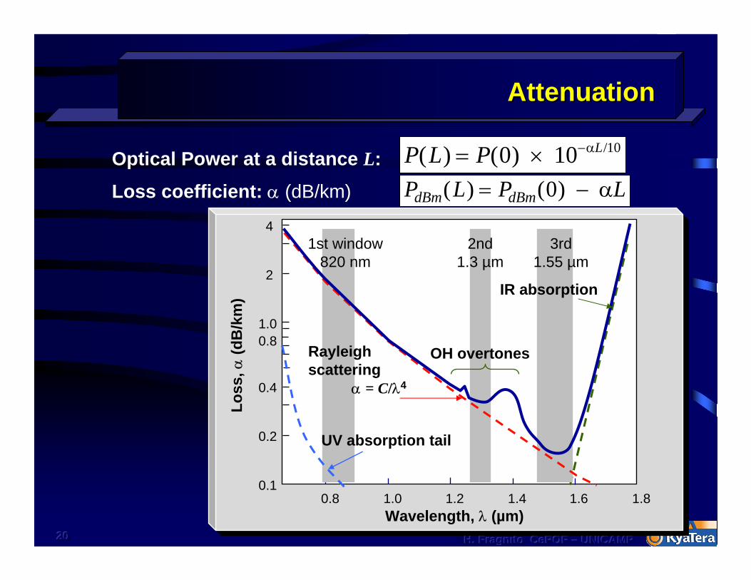
AttenuationAttenuation
Loss
, α(d
B/k
m)
Wavelength, λ (µm)
Optical Power at a distance L: P L P L( ) ( ) /= × −0 10 10 α
Loss coefficient: α (dB/km)
0.1
0.2
0.4
0.81.0
0.8 1.0 1.2 1.4 1.6 1.8
2
4
UV absorption tail
Rayleigh scattering
α = C/λ4
OH overtones
1st window820 nm
2nd1.3 µm
3rd1.55 µm
IR absorption
P L P LdBm dBm( ) ( )= −0 α
212121 H. Fragnito H. Fragnito H. Fragnito CePOFCePOFCePOF ––– UNICAMPUNICAMPUNICAMP
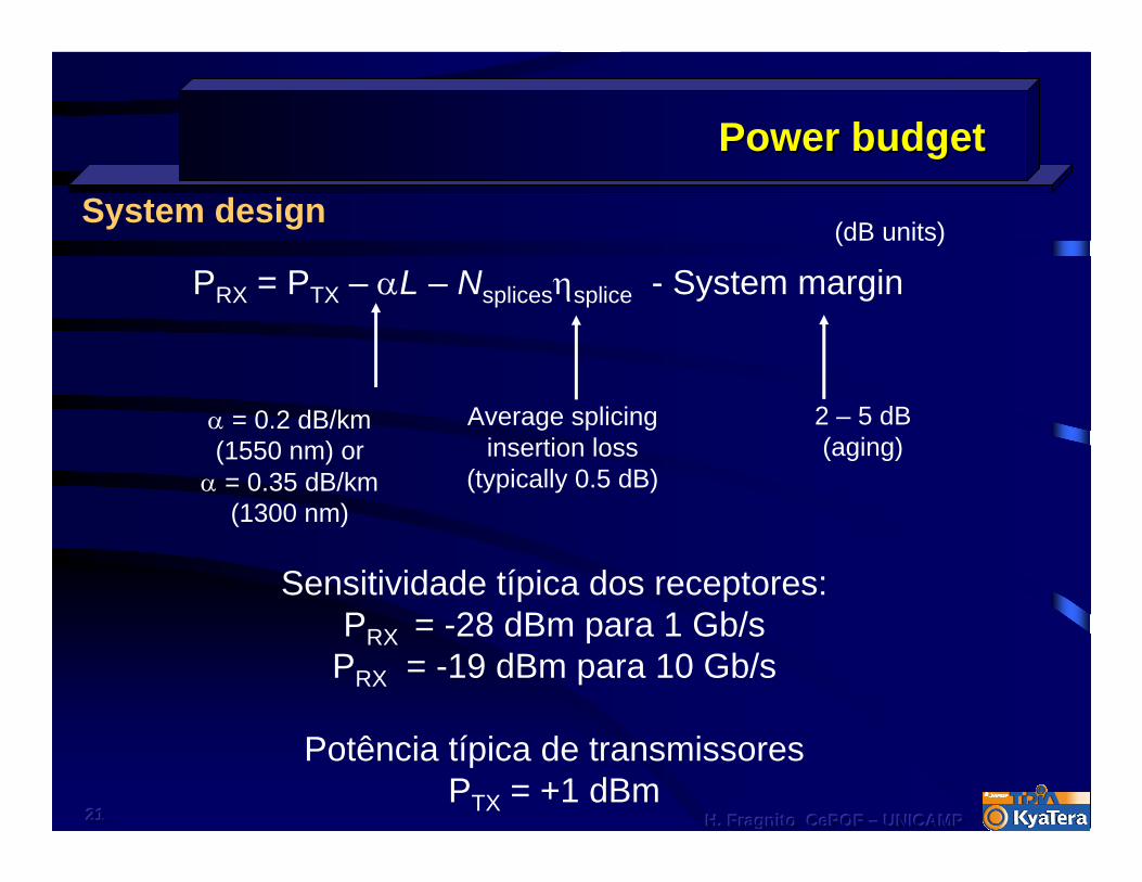
Power budgetPower budget
PRX = PTX – αL – Nsplicesηsplice - System margin(dB units)
Average splicing insertion loss
(typically 0.5 dB)
2 – 5 dB(aging)
Sensitividade típica dos receptores:PRX = -28 dBm para 1 Gb/s
PRX = -19 dBm para 10 Gb/s
Potência típica de transmissoresPTX = +1 dBm
System design
α = 0.2 dB/km (1550 nm) or
α = 0.35 dB/km (1300 nm)
222222 H. Fragnito H. Fragnito H. Fragnito CePOFCePOFCePOF ––– UNICAMPUNICAMPUNICAMP
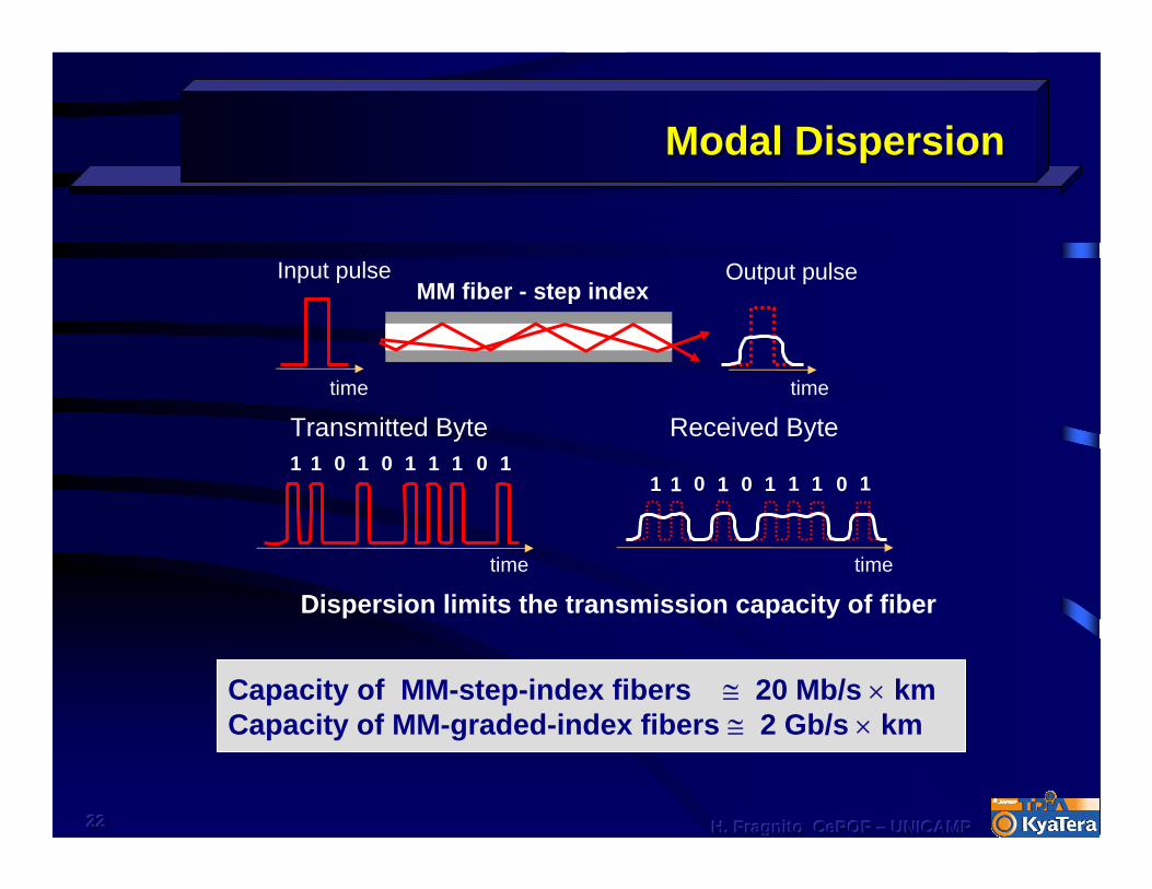
Modal DispersionModal Dispersion
time
1 1 0 1 0 1 1 1 10Transmitted Byte
time
1 1 0 1 0 1 1 1 10
Received Byte
Input pulse Output pulse
timetime
MM fiber - step index
Dispersion limits the transmission capacity of fiber
Capacity of MM-step-index fibers ≅ 20 Mb/s × kmCapacity of MM-graded-index fibers ≅ 2 Gb/s × km

232323 H. Fragnito H. Fragnito H. Fragnito CePOFCePOFCePOF ––– UNICAMPUNICAMPUNICAMP
Material dispersionMaterial dispersion
FIR IR VIS UV
01
n(ω)
Frequency, ω
α(ω)
Vibrational bands
Electronic transitions
Rotational bands (gases & liquids)
\\hugo\cursos\F641\dispers.org 18-apr-95
0.4 0.6 0.8 1.0 1.2 1.4 1.6 1.81.43
1.44
1.45
1.46
1.47
1.48
1.49Silica glass
λ (µm)
Refractive index,n( λ)

242424 H. Fragnito H. Fragnito H. Fragnito CePOFCePOFCePOF ––– UNICAMPUNICAMPUNICAMP
Dispersion parameterDispersion parameter
Measurement of Group Velocity Dispersion (GVD):
Received pulsesInput pulses(different wavelength)
time
Single mode fiber, length L δτ
λλ
λ + δλλ + δλ
DL
=1 δτ
δλDispersion parameter [ps/nm/km]
time

252525 H. Fragnito H. Fragnito H. Fragnito CePOFCePOFCePOF ––– UNICAMPUNICAMPUNICAMP
Chromatic dispersionChromatic dispersion
D = DM + DW
Group velocity (vg) depends on λ
Dispersion parameter:
DM (Material Dispersion):n depends on λ
DW (Waveguide Dispersion): vg depends on waveguide geometry
D (total)
DM
DW
λ0
0
D(p
s/nm
/km
)
-20
20
1.2 1.4 1.6
Zero dispersion wavelength
standard SMF (ITU G.652)
17 ps/nm/km @ 1550 nm
26
Some system componentsSome system components
Diode LasersDetectors
ModulatorsIntegrated optics: Mux
Amplifiers
272727 H. Fragnito H. Fragnito H. Fragnito CePOFCePOFCePOF ––– UNICAMPUNICAMPUNICAMP
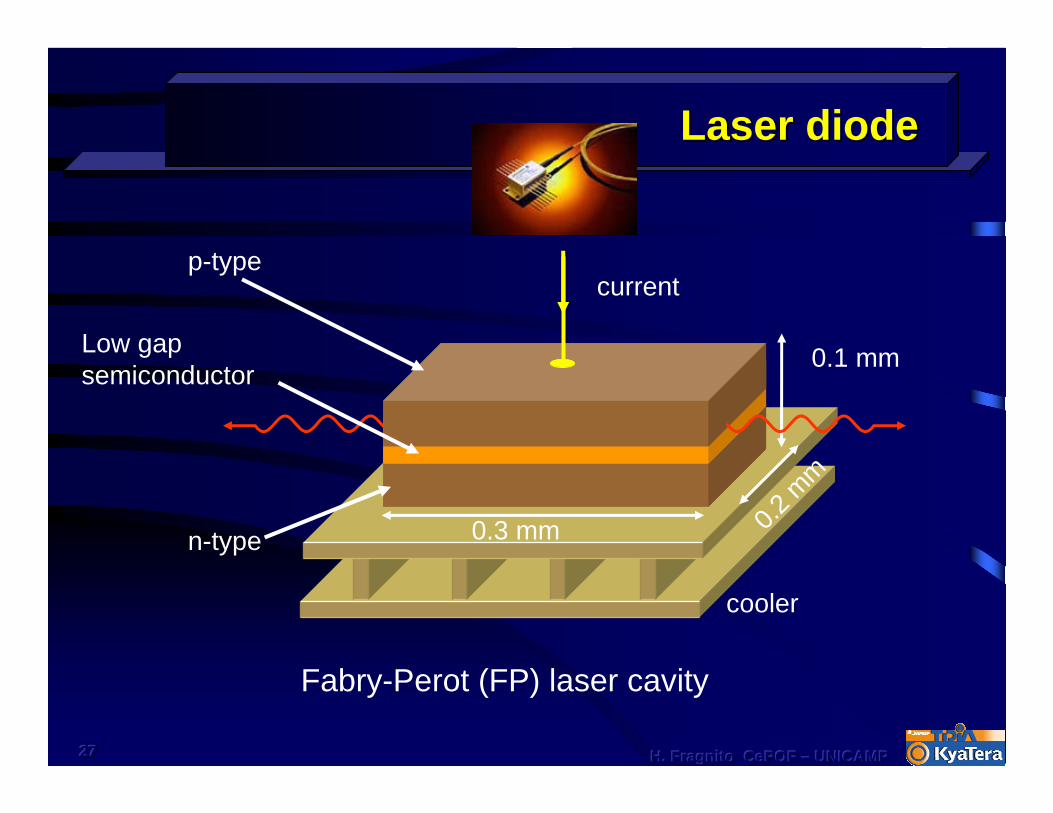
p-type
Low gap semiconductor
n-type
current
0.3 mm 0.2 m
m
0.1 mm
cooler
Laser diodeLaser diode
Fabry-Perot (FP) laser cavity
282828 H. Fragnito H. Fragnito H. Fragnito CePOFCePOFCePOF ––– UNICAMPUNICAMPUNICAMP
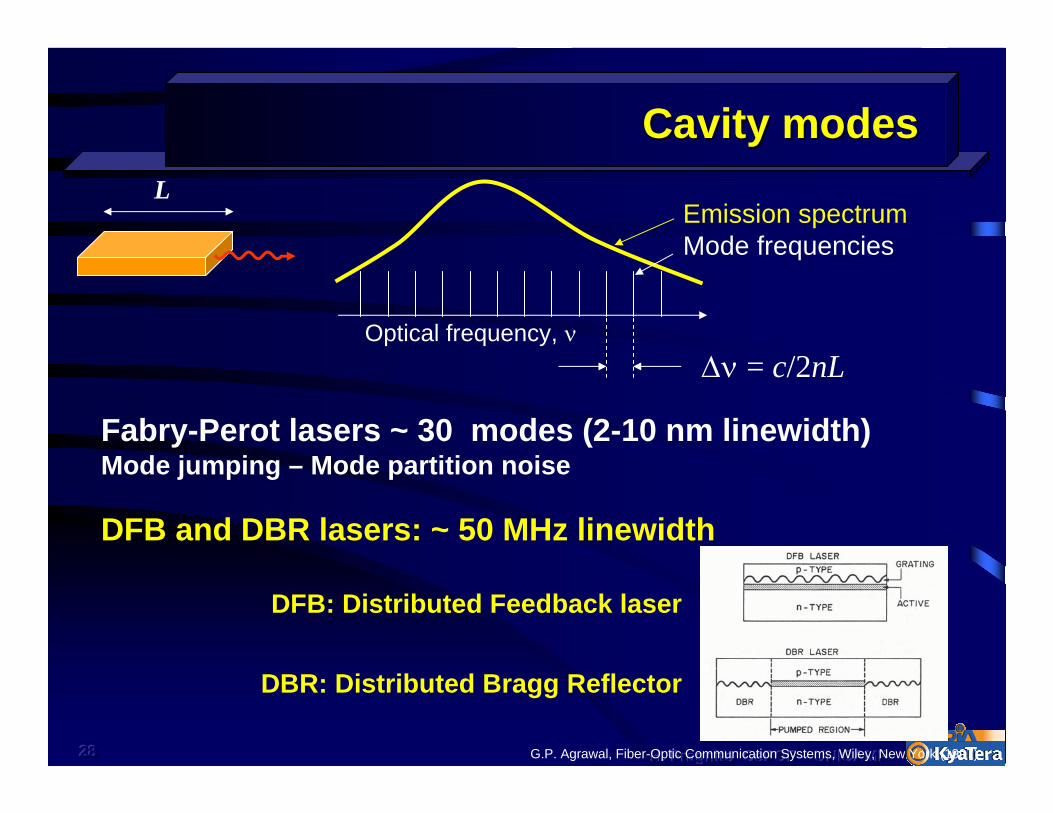
Cavity modesCavity modes
Emission spectrumMode frequencies
∆ν = c/2nL
L
Fabry-Perot lasers ~ 30 modes (2-10 nm linewidth) Mode jumping – Mode partition noise
DFB: Distributed Feedback laser
DBR: Distributed Bragg Reflector
DFB and DBR lasers: ~ 50 MHz linewidth
G.P. Agrawal, Fiber-Optic Communication Systems, Wiley, New York (1997)
Optical frequency, ν
292929 H. Fragnito H. Fragnito H. Fragnito CePOFCePOFCePOF ––– UNICAMPUNICAMPUNICAMP
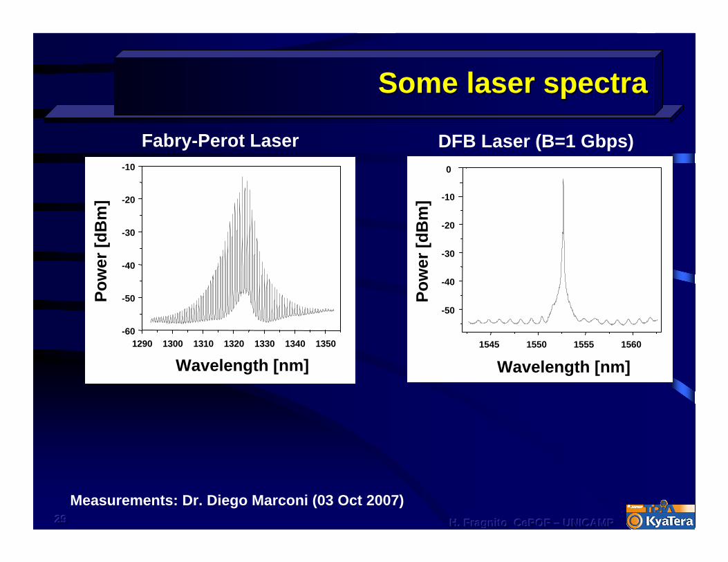
Some laser spectraSome laser spectra
Wavelength [nm]
Pow
er[d
Bm
]
1545 1550 1555 1560
-50
-40
-30
-20
-10
0
1290 1300 1310 1320 1330 1340 1350-60
-50
-40
-30
-20
-10
Wavelength [nm]
Pow
er[d
Bm
]
Fabry-Perot Laser
Measurements: Dr. Diego Marconi (03 Oct 2007)
DFB Laser (B=1 Gbps)
303030 H. Fragnito H. Fragnito H. Fragnito CePOFCePOFCePOF ––– UNICAMPUNICAMPUNICAMP
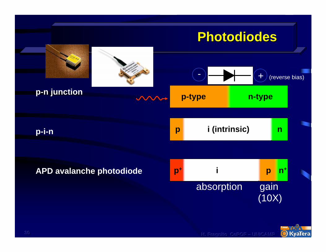
PhotodiodesPhotodiodes
p-n junction
p-i-n
APD avalanche photodiode
p-type n-type
p+ i p n+
i (intrinsic)p n
absorption gain(10X)
+ (reverse bias)-
313131 H. Fragnito H. Fragnito H. Fragnito CePOFCePOFCePOF ––– UNICAMPUNICAMPUNICAMP
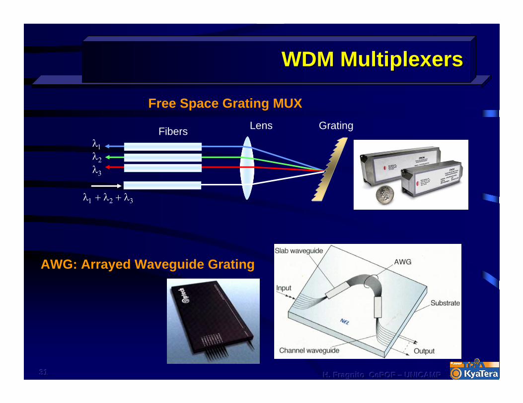
WDM MultiplexersWDM Multiplexers
AWG: Arrayed Waveguide Grating
Free Space Grating MUXGratingLensFibers
λ1 + λ2 + λ3
λ3
λ2
λ1

323232 H. Fragnito H. Fragnito H. Fragnito CePOFCePOFCePOF ––– UNICAMPUNICAMPUNICAMP
V
0
ModulatorsModulators
• Mach-Zehnder• Switching voltage: 5 - 8 V• Up to 60 Gb/s• Integrated optics• Fiber pigtail
LiNbO3 substrate
Waveguide (Ti in-diffused)
Waveguide Electro-Optic Switch (KyaTera)

333333 H. Fragnito H. Fragnito H. Fragnito CePOFCePOFCePOF ––– UNICAMPUNICAMPUNICAMP
Electroabsorption modulatorElectroabsorption modulator
Franz-Keldysh effect: energy gap of semiconductors depends on applied electric field
Effect is enhanced in Multiple Quantum Wells
50 GHz, 2V
Integrated with laser in the same chip
absorbing MQW layers
p-con
tact
p-type
n-type
n-typ
e sub
strate
343434 H. Fragnito H. Fragnito H. Fragnito CePOFCePOFCePOF ––– UNICAMPUNICAMPUNICAMP
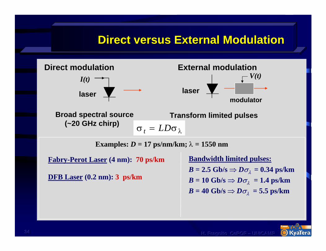
Direct versus External ModulationDirect versus External Modulation
Broad spectral source (~20 GHz chirp)
Bandwidth limited pulses:B = 2.5 Gb/s ⇒ Dσλ = 0.34 ps/kmB = 10 Gb/s ⇒ Dσλ = 1.4 ps/kmB = 40 Gb/s ⇒ Dσλ = 5.5 ps/km
Transform limited pulses
σ σ λt LD=
Fabry-Perot Laser (4 nm): 70 ps/km
DFB Laser (0.2 nm): 3 ps/km
External modulationDirect modulation
Examples: D = 17 ps/nm/km; λ = 1550 nm
I(t)
laser
V(t)
lasermodulator
353535 H. Fragnito H. Fragnito H. Fragnito CePOFCePOFCePOF ––– UNICAMPUNICAMPUNICAMP
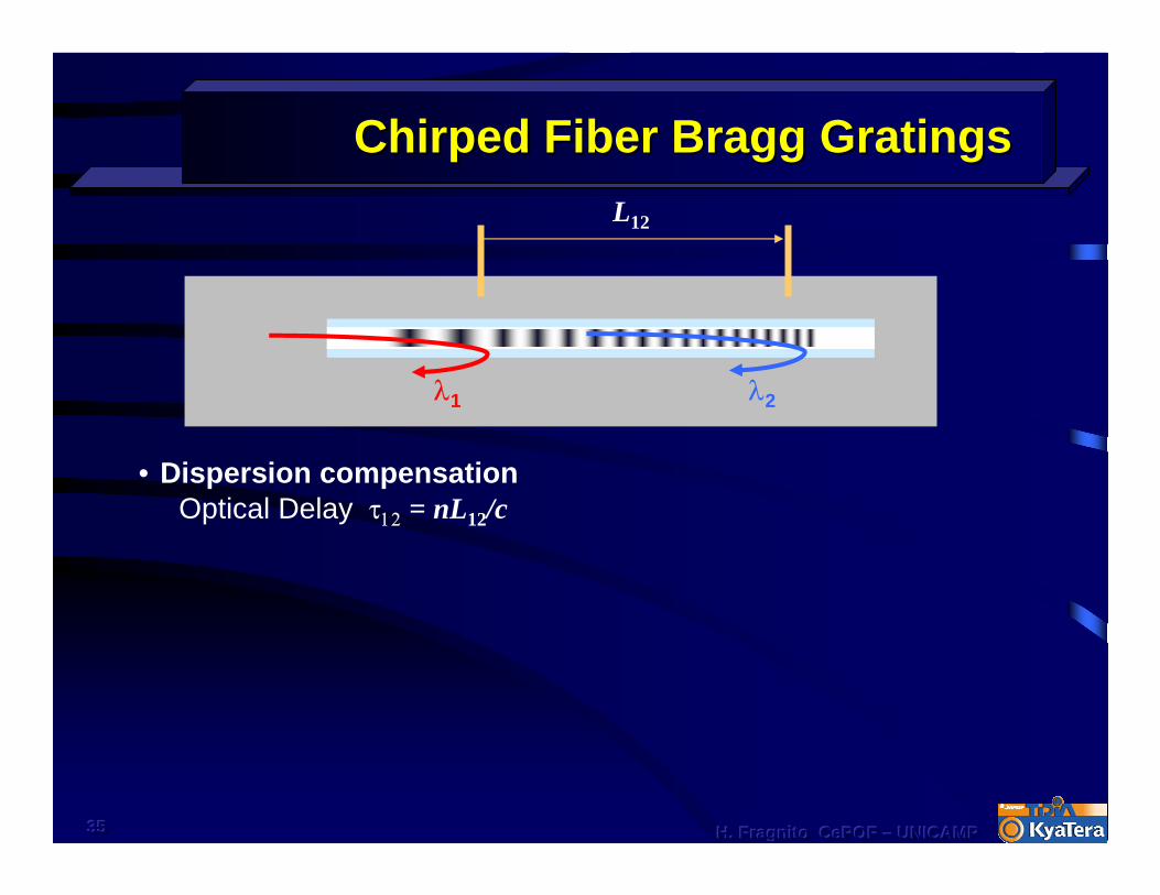
Chirped Fiber Bragg GratingsChirped Fiber Bragg Gratings
λ1 λ2
L12
• Dispersion compensationOptical Delay τ12 = nL12/c
36
Optical AmplifiersOptical Amplifiers
373737 H. Fragnito H. Fragnito H. Fragnito CePOFCePOFCePOF ––– UNICAMPUNICAMPUNICAMP
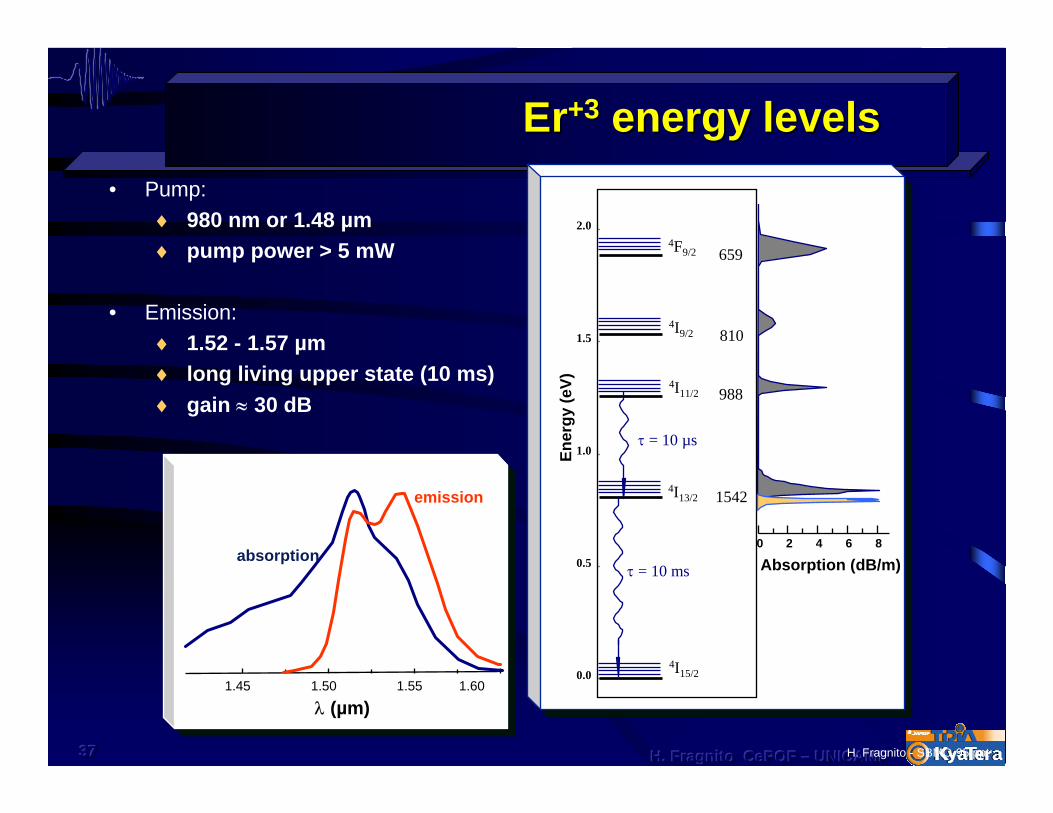
ErEr+3+3 energy levelsenergy levels• Pump:
♦ 980 nm or 1.48 µm ♦ pump power > 5 mW
• Emission:♦ 1.52 - 1.57 µm♦ long living upper state (10 ms)♦ gain ≈ 30 dB
Absorption (dB/m)
4F9/2
0.0
0.5
1.0
1.5
2.0
1542
988
810
659
τ = 10 msEn
ergy
(eV)
0 2 4 6 8
λ (nm)
4I9/2
4I11/2
4I13/2
4I15/2
τ = 10 µs
1.45 1.50 1.55 1.60
absorption
emission
λ (µm)
H. Fragnito - SBMO-95.ppt

383838 H. Fragnito H. Fragnito H. Fragnito CePOFCePOFCePOF ––– UNICAMPUNICAMPUNICAMP
Characteristics of EDFA based SystemsCharacteristics of EDFA based Systems
Bandwidth > 4 THzdepends on glass host(100 nm in Telurite glass)
Low noise
Optical power > 100 mWlarger distance between EDFAs
Transparent to bit rate, modulation format, and bit coding (transmission protocol)
Ideal for WDM (Wavelength Division Multiplexing)
15
20
30
Gai
n (d
B)
Wavelength (nm)1500 1520 1540 1560 1580
35 nm
393939 H. Fragnito H. Fragnito H. Fragnito CePOFCePOFCePOF ––– UNICAMPUNICAMPUNICAMP
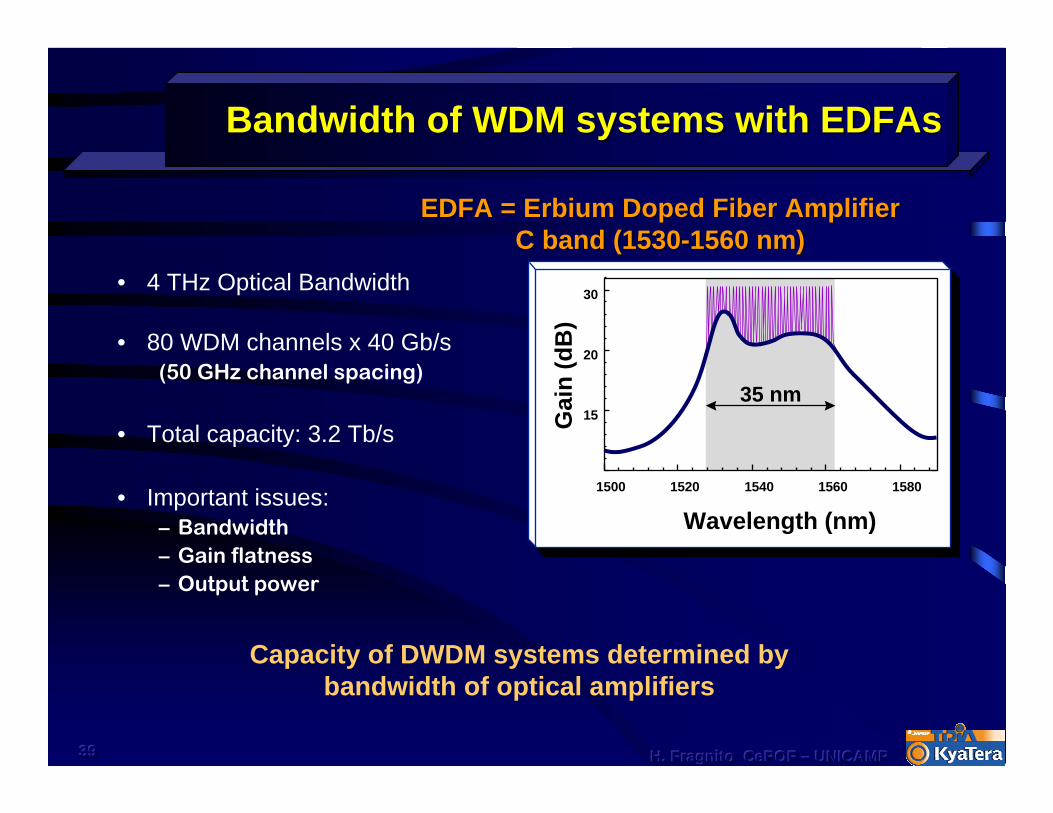
Bandwidth of WDM systems with Bandwidth of WDM systems with EDFAsEDFAs
• 4 THz Optical Bandwidth
• 80 WDM channels x 40 Gb/s(50 GHz channel spacing)
• Total capacity: 3.2 Tb/s
• Important issues:– Bandwidth– Gain flatness– Output power
15
20
30
Gai
n (d
B)
Wavelength (nm)1500 1520 1540 1560 1580
35 nm
EDFA = Erbium Doped Fiber AmplifierEDFA = Erbium Doped Fiber AmplifierC band (1530C band (1530--1560 nm)1560 nm)
Capacity of DWDM systems determined by bandwidth of optical amplifiers

404040 H. Fragnito H. Fragnito H. Fragnito CePOFCePOFCePOF ––– UNICAMPUNICAMPUNICAMP
Optical Amplifiers for DWDMOptical Amplifiers for DWDM
EDFA (1510-1620 nm) Erbium
TDFA (1440-1510 nm) Thulium
SOA (60 nm bandwidth) Semiconductor Optical Amplifier
Raman Amplifiers (40 nm bandwidth; choice of spectral region)
1520 1540 1560 1580 1600 1620 16400
10
20
30
40
Gai
n (d
B)
Wavelength (nm)
C-band L-bandEDFAs
90 nm
Ram
an G
ain,
dB
Signal Wavelength, nm1460 1500 1540 1580 16200
5
10
15
20
Raman Gain

414141 H. Fragnito H. Fragnito H. Fragnito CePOFCePOFCePOF ––– UNICAMPUNICAMPUNICAMP
Gain Flattening Filter Gain Flattening Filter –– GFFGFF
λ1 λ2
Grating with varying index modulation depth
M. Guy and F. Trépanier, WDM, March 2001

42
The FutureThe Future
Niels Bohr1922 Nobel Prize in Physics
“Prediction is very difficult, especially
if it’s about the future.”

43
Internet in the futureInternet in the future20 years ago
Telephony network64 kb/s per voice circuitPassive user
Today Network with variety of uses/services (voice, data, video, radio,…) User generated content (wikis, youtubes, blogs, mushups,…)Mb/s per user> 1 billion internautsCost per bit reduced by one million
But, a jungle of technologies (with different languages) – Tower of Babel100 billion spam/day, viruses, insecure, vulnerable, fragileIncreasing socioeconomic dependence of the Internet
TomorrowInfinity of applications and contentSuper high resolution video5 billion users – Gb/s per user (and we humans will be minority…)FTTHSecure, robust, inexpensive broadband Internet, convergence of technologies
Which scientific advances will enable such future?
100 to 1000 increase in capacity in 20 years
Metropolis, Fritz Lang (1927)

44
100 to 1000 times the present capacity?100 to 1000 times the present capacity?
Grand challenges for optical communications:1. Technology Problem:
● DWDM today 40 channels – does it scale to 4000 channels? ● Today’s amplifier technology does not scale● Electronic routing technology does not scale
2. Real state problem3. Energy consumption problem4. Costs: big problem
Perceived paths:● Optical amplifiers for the whole high-transparency window of
silica● Integrated optical circuits (hundred lasers in a chip)● All optical networking● …
45
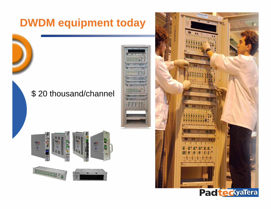
DWDM equipment today
$ 20 thousand/channel
46
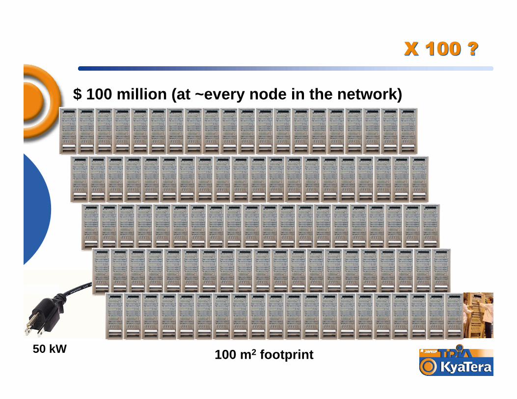
50 kW
X 100 ?X 100 ?
100 m2 footprint
$ 100 million (at ~every node in the network)
47
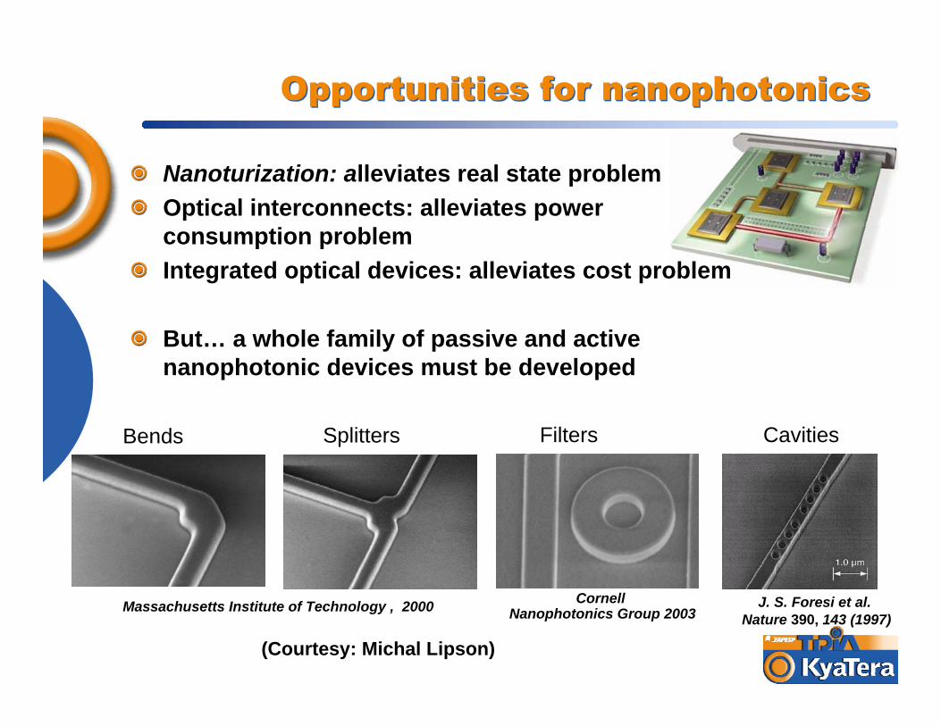
Opportunities for nanophotonicsOpportunities for nanophotonics
Nanoturization: alleviates real state problemOptical interconnects: alleviates power consumption problemIntegrated optical devices: alleviates cost problem
But… a whole family of passive and active nanophotonic devices must be developed
Massachusetts Institute of Technology , 2000
Bends Splitters CavitiesFilters
Cornell Nanophotonics Group 2003
J. S. Foresi et al. Nature 390, 143 (1997)
(Courtesy: Michal Lipson)

48
10 DWDM transmitters/receivers in an InP chip (Infinera)
4 mm
The real state problemThe real state problem
49
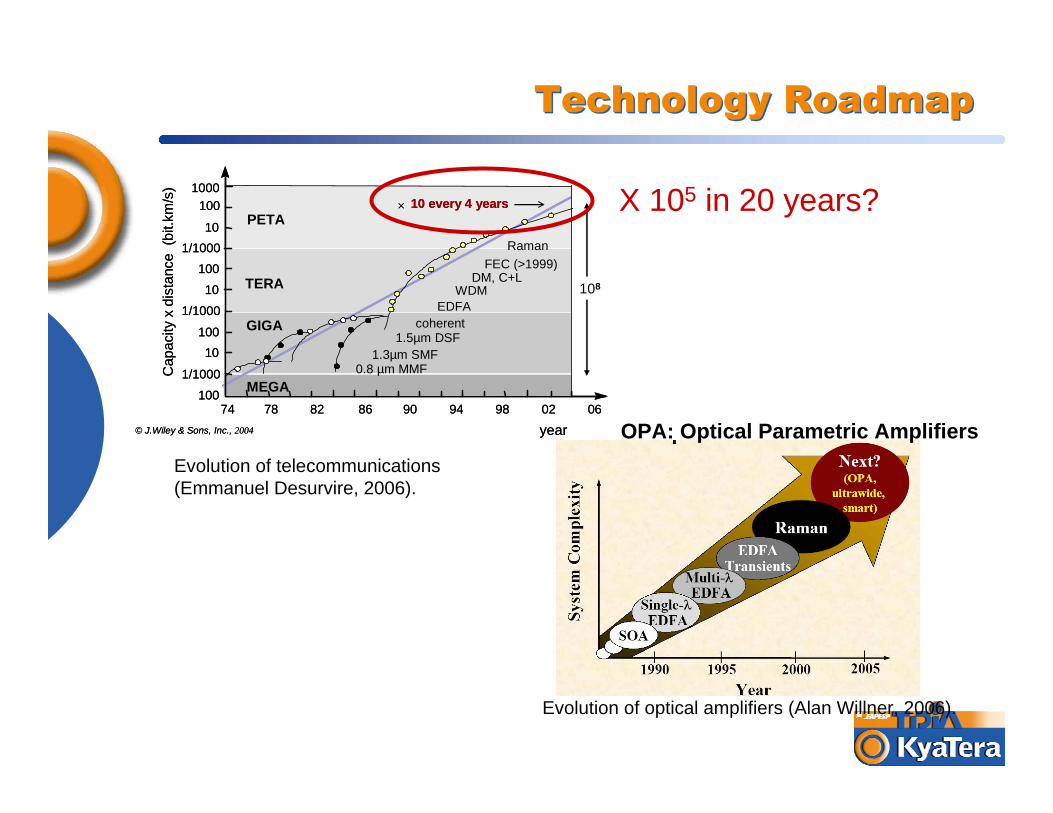
Technology RoadmapTechnology Roadmap
74 78 82 86 90 94 98 02 06
101/1000
10010
1/1000
10010
1/1000100
Cap
acity
x di
stan
ce (
bit.k
m/s
)
year
PETA
TERA
GIGA
MEGA
FEC (>1999)
0.8 µm MMF1.3µm SMF
1.5µm DSFcoherent
100
108
10 every 4 years×
EDFAWDM
DM, C+L
1000
© J.Wiley & Sons, Inc., 2004
Raman
74 78 82 86 90 94 98 02 06
101/1000
10010
1/1000
10010
1/1000100
Cap
acity
x di
stan
ce (
bit.k
m/s
)
year
PETA
TERA
GIGA
MEGA
FEC (>1999)
0.8 µm MMF1.3µm SMF
1.5µm DSFcoherent
100
108
10 every 4 years× 10 every 4 years×
EDFAWDM
DM, C+L
1000
© J.Wiley & Sons, Inc., 2004
Raman
Evolution of telecommunications (Emmanuel Desurvire, 2006).
OPA: Optical Parametric Amplifiers
Evolution of optical amplifiers (Alan Willner, 2006).
X 105 in 20 years?
505050 H. Fragnito H. Fragnito H. Fragnito CePOFCePOFCePOF ––– UNICAMPUNICAMPUNICAMP
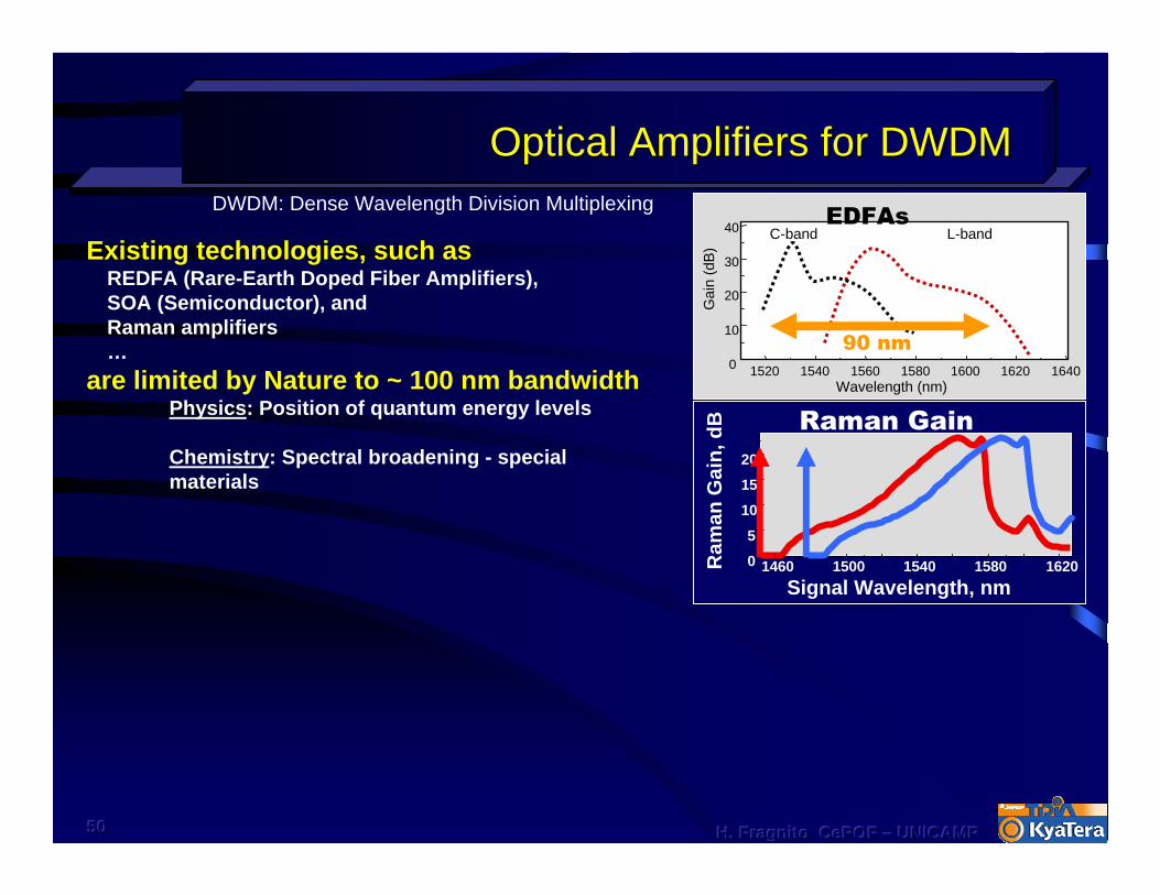
Optical Amplifiers for DWDMOptical Amplifiers for DWDM
Existing technologies, such asREDFA (Rare-Earth Doped Fiber Amplifiers), SOA (Semiconductor), andRaman amplifiers…
are limited by Nature to ~ 100 nm bandwidthPhysics: Position of quantum energy levels
Chemistry: Spectral broadening - special materials
1520 1540 1560 1580 1600 1620 16400
10
20
30
40
Gai
n (d
B)
Wavelength (nm)
C-band L-bandEDFAs
90 nm
Ram
an G
ain,
dB
Signal Wavelength, nm1460 1500 1540 1580 16200
5
101520
Raman Gain
DWDM: Dense Wavelength Division Multiplexing

515151 H. Fragnito H. Fragnito H. Fragnito CePOFCePOFCePOF ––– UNICAMPUNICAMPUNICAMP
FOPAsFOPAs
Existing technologies, such asREDFA (Rare-Earth Doped Fiber Amplifiers), SOA (Semiconductor), andRaman amplifiers…
are limited by Nature to ~ 100 nm bandwidthPhysics: Position of quantum energy levels
Chemistry: Spectral broadening - special materials
1520 1540 1560 1580 1600 1620 16400
10
20
30
40
Gai
n (d
B)
Wavelength (nm)
C-band L-bandEDFAs
90 nm
Ram
an G
ain,
dB
Signal Wavelength, nm1460 1500 1540 1580 16200
5
101520
Raman Gain
FOPAs – Fiber Optic Parametric AmplifiersBandwidth and spectral region can be engineered by choosing waveguide dispersion
… controllable by waveguide design
J. M. Chavez Boggio, J. D. Marconi, S. R. Bickham, and H. L. Fragnito, Optics Express 15, 5288-5309, 2007.
DWDM: Dense Wavelength Division Multiplexing
Wavelength (nm)
Gai
n(d
B) 115 nm
λ1 λ2
λ0
1450 1500 1550 1600 16500
4
8
12
16
20
24
28
Wavelength (nm)
Gai
n(d
B) 115 nm
λ1 λ2
λ0
1450 1500 1550 1600 16500
4
8
12
16
20
24
28
Wavelength (nm)
Gai
n(d
B) 115 nm
λ1 λ2
λ0
1450 1500 1550 1600 16500
4
8
12
16
20
24
28

525252 H. Fragnito H. Fragnito H. Fragnito CePOFCePOFCePOF ––– UNICAMPUNICAMPUNICAMP
FOPAsFOPAsFOPAs
• Based on nonlinear refractive index
• Pump laser near zero dispersion wavelength
• Idler wave generated – can be used as wavelength converter
• Typical pump power, fiber length, gain, bandwidth:– P = 0.1 – 1 W, but few mW in nanophotonic waveguides– L = 0.2 – 5 km, but few cm in nanophotonic waveguides– G = 20 – 40 dB (up to 70 dB demonstrated) – ∆λ3dB = 20 – 60 nm ( > 100 nm demonstrated)
Fiber-Optic Parametric Amplifiers
ωp ωsωi
ωi = 2ωp - ωs
signal
pump
idler
535353 H. Fragnito H. Fragnito H. Fragnito CePOFCePOFCePOF ––– UNICAMPUNICAMPUNICAMP
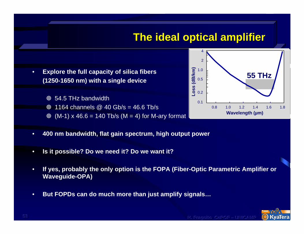
The ideal optical amplifierThe ideal optical amplifier
• Explore the full capacity of silica fibers (1250-1650 nm) with a single device
54.5 THz bandwidth1164 channels @ 40 Gb/s = 46.6 Tb/s(M-1) x 46.6 = 140 Tb/s (M = 4) for M-ary format
• 400 nm bandwidth, flat gain spectrum, high output power
• Is it possible? Do we need it? Do we want it?
• If yes, probably the only option is the FOPA (Fiber-Optic Parametric Amplifier or Waveguide-OPA)
• But FOPDs can do much more than just amplify signals…Lo
ss (d
B/k
m)
Wavelength (µm)0.8 1.0 1.2 1.4 1.6 1.8
0.1
0.2
0.5
1.0
2
4
55 THz
545454 H. Fragnito H. Fragnito H. Fragnito CePOFCePOFCePOF ––– UNICAMPUNICAMPUNICAMP
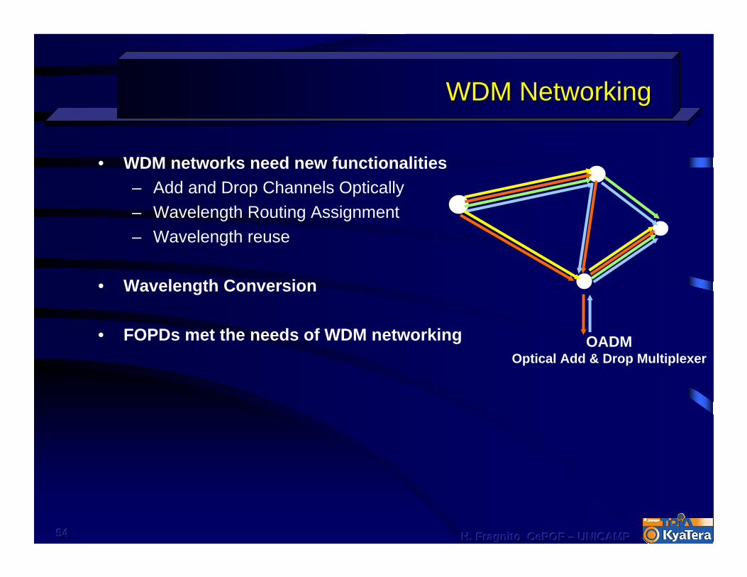
WDM NetworkingWDM Networking
• WDM networks need new functionalities– Add and Drop Channels Optically– Wavelength Routing Assignment– Wavelength reuse
• Wavelength Conversion
• FOPDs met the needs of WDM networking OADMOptical Add & Drop Multiplexer

55
Questions?Questions?