Tutorial: Mapping Adhesion Forces and Calculating … · other than physics, such as biomedical...
8
Microscopy and Analysis 20(2):S5-S8 (UK), 2006 Tutorial: Mapping Adhesion Forces and Calculating Elasticity in Contract – Mode AFM Marco Salerno and Ivan Bykov 1. NBNL-CNR, Lecce, Italy 2. NT-MDT, Moscow, Russia BIOGRAPHY Marco Salerno is currently a researcher at the National Nanotechnolgy Lab of Lecce. After receiving his MSe from the University of Pisa in 1993 for atomic microscopy investigations of surface friction, he worked on the development of a neural network- driven AFM (1997, Elba Island). He received his PhD from the University of Graz, Austria, in 2002 for a near-field scanning optical microscopy study of plasmons and then worked as a postdoc in Modena where he used electrochemical scanning tunnelling microscopy to study biomoiecules. ABSTRACT Over the past ten years the atomic force microscope has developed more and more into a spectroscopic tool rather than a simple microscope. Still, for most non-expert users corning from fields other than physics, such as biomedical scientists, dealing with the advanced spectroscopic AFM techniques beyond imaging is not so simple. This tutorial answers some how-to-do-it questions concerning the most common operations in AFM force-spectroscopy, namely mapping adhesion or more general force distributions, and calculating Young's modulus. KEYWORDS tutorial, scanning probe microscopy, atomic force microscopy, force-distance curve, force-volume, adhesion, Young's modulus ACKNOWLEDGEMENTS The authors thank the National Nanotech-nology Lab of Lecce and in particular Pro¬fessor G. Gigli for providing access to the AFM equipment. AUTHOR DETAILS Dr Marco Salerno, National Nanotechnology Lab of Lecce, via per Arnesano km 5, 73100 Lecce, Italy. Tel: +39 0832 29 8236 Email: [email protected] INTRODUCTION Scanning probe microscopes (SPMs) have been providing investigators with a resolution far beyond the diffraction limit of optical microscopy for more than two decades. Today, the atomic force microscope (AFM) is the most widespread type of SPM due to the variety of available combinations of environment (air, vacuum, liquid) and types of samples (semiconductor, organic, biological) that it can investigate. The AFM is so versatile that any kind of interaction between its probe and the sample can be sensed, as long as it generates a force that can be measured by the elastic cantilever beam holding the tip. Measurement of the vertical interaction force in AFM is a key task, both to obtain high-quality artifact- free topographical imaging and to gather independent information on the physical and chemical properties of the tip-sample interaction resulting from the compositional and structural properties of the sample [1]. The aim of this tutorial is to show how to use the AFM to acquire images of tip-sample adhesion and to determine the local sample compliance with sub-micrometre resolution. SCOPE AND LIMITATIONS
Transcript of Tutorial: Mapping Adhesion Forces and Calculating … · other than physics, such as biomedical...

Microscopy and Analysis 20(2):S5-S8 (UK), 2006
Tutorial: Mapping Adhesion Forces and Calculating Elasticity in Contract – Mode AFM
Marco Salerno and Ivan Bykov 1. NBNL-CNR, Lecce, Italy 2. NT-MDT, Moscow, Russia
BIOGRAPHY
Marco Salerno is currently a researcher at the National Nanotechnolgy Lab of Lecce. After receiving his MSe from the University of Pisa in 1993 for atomic microscopy investigations of surface friction, he worked on the development of a neural network-driven AFM (1997, Elba Island). He received his PhD from the University of Graz, Austria, in 2002 for a near-field scanning optical microscopy study of plasmons and then worked as a postdoc in Modena where he used electrochemical scanning tunnelling microscopy to study biomoiecules.
ABSTRACT Over the past ten years the atomic force microscope has developed more and more into a spectroscopic tool rather than a simple microscope. Still, for most non-expert users corning from fields other than physics, such as biomedical scientists, dealing with the advanced spectroscopic AFM techniques beyond imaging is not so simple. This tutorial answers some how-to-do-it questions concerning the most common operations in AFM force-spectroscopy, namely mapping adhesion or more general force distributions, and calculating Young's modulus. KEYWORDS tutorial, scanning probe microscopy, atomic force microscopy, force-distance curve, force-volume, adhesion, Young's modulus ACKNOWLEDGEMENTS The authors thank the National Nanotech-nology Lab of Lecce and in particular Pro¬fessor G. Gigli for providing access to the AFM equipment. AUTHOR DETAILS Dr Marco Salerno, National Nanotechnology Lab of Lecce, via per Arnesano km 5, 73100 Lecce, Italy. Tel: +39 0832 29 8236 Email: [email protected] INTRODUCTION Scanning probe microscopes (SPMs) have been providing investigators with a resolution far beyond the diffraction limit of optical microscopy for more than two decades. Today, the atomic force microscope (AFM) is the most widespread type of SPM due to the variety of available combinations of environment (air, vacuum, liquid) and types of samples (semiconductor, organic, biological) that it can investigate. The AFM is so versatile that any kind of interaction between its probe and the sample can be sensed, as long as it generates a force that can be measured by the elastic cantilever beam holding the tip. Measurement of the vertical interaction force in AFM is a key task, both to obtain high-quality artifact-free topographical imaging and to gather independent information on the physical and chemical properties of the tip-sample interaction resulting from the compositional and structural properties of the sample [1]. The aim of this tutorial is to show how to use the AFM to acquire images of tip-sample adhesion and to determine the local sample compliance with sub-micrometre resolution. SCOPE AND LIMITATIONS

We will focus on static contact-mode AFM (i.e. we will not discuss tapping mode and force modulation) and consider only vertical forces (no lateral force techniques). Therefore, nei¬ther the viscous behaviour nor the friction of the tip-sample interface will be addressed, respectively, as these topics are large enough to merit a separate tutorial. Note that the AFM as a force sensor only measures an interaction force, and little is known a priori about the nature of this interaction; it is up to the researcher to carefully consider its origin and quantify its properties. Further, the bare force-distance curves cannot be directly compared to force-distance theoretical functions representing the physical model of interaction; during measurement of the interaction the deflection of the cantilever is also modifying the actual tip-sample distance, and consequently the force-curve has to be corrected (by algebraically adding the deflection D to the scanner Z position). CONTACT MODE In contact-mode AFM, equilibrium between the tip-sample interaction force Fand the cantilever restoring force Fk, exists when F = -fk = kD, where k is the cantilever spring constant and D is its deflection (Hooke's law). An image of sample topographical height Ah is obtained from the vertical movement Az of a piezoelectric actuator which is necessary to keep D (and thus F) constant at a given set-point DSP, while scanning horizontally on an (x,y) grid under the action of feedback loop electronics (this is constant-force operation). If no tip indentation (i.e. sample deformation) occurs, Д/i = AD = -Az and F(x,y) = FSP -/cAz(x,y), where FSP = /cDSP. Obviously, the apparent topography Ah(x,y) = [F(x,y) - Fsp]+k includes also the local differences in interaction force F. While this can be seen as an artifact for morphological imaging, it can be used to map F(x,y) in force imaging; this is particularly straightforward in the case of a flat, featureless sample, for which Ah(x,y) = 0. The determination of F relies on the knowledge of both the spring constant of the cantilever k, and the conversion factor of the deflection detecting system of the AFM. TOPIC 1: HOW TO DETERMINE THE SPRING CONSTANT OF THE CANTILEVER The spring constant k can be assigned a value in (nano)newtons per (nano)meter in one of the following ways.
A. Use the nominal value k° given by themanufacturer This is usually affected by a large uncertainty (±50%) due to fluctuations in the micro-fabrication processes. However, expensive can¬tilevers with accurate k values are available, which have been individually characterized by the manufacturer. B. Calculate k from the theory of elasticity [3] Given the nominal values of the cantilever geometrical parameters and the material of the beam (see Table 1), k can be determined by the general expression in Eq. 1a (Table 1), where £ is Young's modulus. Common can¬tilevers are made of silicon, silicon nitride
Figure I: Resonant frequency fre' of a contact-mode cantilever (CSGIO from Ш-MDl see fable Ij determined by tapping-mode software, [be deviation of frK' from the nominal ralue f,K° (yellow vertical line) can be used to correct the nominal spring constant k° (see Topic 1, method) (Si3N4) or silicon coated with gold or magnetic alloys; the metal coatings have little effect on cantilever elasticity. A practical formula for silicon cantilevers is given by Eq. 1b. Similarly, by

calculation using a finite element method mechanical analysis, a k can be determined that also accounts for the mass of the probe tip. In any case, whereas the dimensions of both cantilever and tip can be accurately determined by optical and electron microscopy, the exact properties of the material are hardly known, such that the uncertainty of this method can be estimated to ± 15%. C. Determine k indirectly from the resonantfrequency of the cantilever As the cantilever beam is an elastic spring that can be modelled as an harmonic oscillator, k is related to the resonant frequency fres by Eq. 2, where m* is the equivalent mass of the cantilever-tip assembly. fres can be measured with high accuracy by means of a spectrum analyzer, an electronic tool that measures the mechanical response of the cantilever to a white (flat frequency) thermal noise excitation. The main difficulty is here in estimating m*. However, at first approximation the tip can be neglected and, as long as the cantilever is new, no extra load is present due to contamination from sample and environment. If p is the density of the cantilever material (so that its mass m = pw/t), due to its distribution along the length of the cantilever, m is roughly equivalent to a concentrated mass m*, equal to about one fourth of m, placed at the end of the beam [4]. Therefore, on inversion of Eq. 2 the general expression in Eq. За can be obtained for k, and hence the corresponding practical formula (Eq. 3b) for silicon cantilevers. D. Correct the nominal /r° value from themanufacturer with respect to measured fres Although an expensive tool, the spectrum analyzer can be efficiently replaced by an AFM controller enabled with tapping (semicontact) mode capability. These electronics contain either a lock-in amplifier or a peak detector, which makes it possible to find the resonant frequency of tapping-mode cantilevers. The same function can also be used for contact-mode cantilevers, the only difference being a much lower fres, as well as k. In this case, the problem associated with the uncertainty of m*is somewhat circumvented by assuming that, compared to the nominal geometrical dimen¬sions, the overall deviations do not greatly affect the cantilever volume V = Iwt. There¬fore, the effective mass is still m* » pV^-4 and the measurement of a resonant frequency r"res' different from the nominal value r"res’ can be directly correlated with a difference in spring constant from k° to k', as expressed in Eq. 4. Method D is the best as it is easy and fast and is affected by the smallest error; actually it takes into account both the theoretical and the experimental knowledge available, namely the experience of the manufacturer on lots of cantilevers and users' observations of their cantilever. More methods exist, such as calibrating k versus a known force (or cantilever), or adding a known mass to the can¬tilever and measuring the deviation in k from the observed deviation in fres. However, these methods require known standards and are generally not very practical. After having evaluated k, to determine F in physical units (nN) from the corresponding D value in units of the detection system (n A from the photocells) one needs to calibrate the detection system. As a prerequisite for this, the reader is supposed to know the general prop¬erties of a force-distance AFM curve. An exam¬ple of a force curve is shown in Figure 2 in which a few typical features are pointed out: region of no tip-sample interaction (0-1), jump-to-contact (1-2), contact regions in both approach and retraction branches (2-3 and 4-5, respectively), and jump-off contact (5-6). For further details see [5].

TOPIC 2: HOW TO CALIBRATE THE DEFLECTION DETECTING SYSTEM An AFM deflection D is typically detected via the angular deviation of a laser beam reflected from the back of the cantilever (optical lever method). The laser spot is incident on a multiple segment photodiode, and the sensitivity S of the detector is defined in terms of nanometres of change in D for a given change in the detected signal of photocurrent /, that is S = AD-^ A/. Proper adjustment of the spot close to the end of the cantilever is critical for high sensitivity. S is determined when the tip and sample are in contact and no significant indentation of the sample surface is observed, which is most often the case for non-biological samples. In these conditions along the contact region of the force-curve the Z movement of the cantilever base is transferred one-to-one into cantilever deflection D (i.e. Az = AD), and the slope of this straight segment is S (see Figure 2). As the first step, one (or more) force-curves must be acquired. First, engage the AFM in contact mode and collect an image of the sample. Then, select the spectroscopic mode of the software. Set the independent quantity to be scanned to the Z position, and the dependent quantity detected and plotted as a function of the former to deflection. Then set the acquisition mode to an individual force curve at a given point (x,y). Fill in the scan limits (min and max are the values in nm between which the Z position is ramped, defined positive as moving tip and sample away from each other, with zero being the Z position of engaged contact at setpoint; min = 0 and max = 730 in Figure 2). In order not to overcome a fixed force value, a limit on the maximum deflection can usually be set, such that the approach is stopped if during the ramp this D value is reached. Finally, select with the mouse the point of the previously acquired image where you want the force-curve to be taken. A flat region, at least 1 urn away from any edge, should always be chosen for a clear interpretation of the measurements. The reproducibility should also be checked by acquiring several curves at the same point. Select the window containing the acquired force curves, and after checking that they all look similar, pick one for processing. In the plot window, select only the approach or retract branch of the curve. Select the segment tracing tool and pick up two distant points on the positive side of the straight contact part of the curve (e.g. 3 and 4 in Figure 2). The software will show the increments of the plotted quantities (Ax in nm and Ay in nA), such that the sensitivity S of the system can be calculated (S = Ay-^ Ax). TOPIC 3: EXTRACTING QUANTITIES FROM A FORCE CURVE Apart from the sensitivity of the detection system, the following fundamental information can be obtained from a typical force curve. The actual working deflection (i.e. force) used for imaging This is the difference between the deflection setpoint DSP set in the system before engagement, and the D value at which the zero force level (the horizontal white line in Figure 2) intercepts the D axis. In Figure 2, for example, the zero force level does not correspond to 0 deflection signal, as the photocells were obviously not centred (-0.5 nA initial offset, with setpoint DSP = 0 nA). Therefore, the actual deflection is AD + 0.5 nA (and F = Fsf+ /cAD). This offset helps work in the central region of the photocells to maximize the dynamic range of the detector. However, on approach, deviations from the original offset can occur, so it is a good idea to check this by means of the force curve. Hysteresis of the Z piezo actuator As shown in Figure 2, in the contact region a significant difference between the approach and retract branches of the curve shows up, which is clearly an artifact due to piezo hysteresis in Z. Actually, the blue retract trace should also cross the zero-force level at point 3. As a measure of this effect, the

horizontal difference between the intercepts of the approach and retract branches of the curve with the zero-force level can be taken. Tip-sample adhesion This is associated with another hysteretic behaviour of the force curve that, unlike the previous one, is due to a property of the tip-sample interface and not to imperfect performance of the system. A strong adhesion is clear when a high difference in horizontal (Z) position of the jump-to-contact and jump-off-contact points (2 and 6 in Figure 2) shows up. In normal imaging this effect is usually checked to estimate the cleanliness of the tip, and should be minimized. However, it can be used to provide a quantitative evaluation of adhesion. The area enclosed in the force loop (in the absence of Z piezo hysteresis) represents the work done in the approach-retract cycle by the tip-sample interaction. In particular, the amount of force just before the jump-off-contact gives a measurement of the maximum tip-sample adhesion. The user should keep in mind that, as a dynamic mechanism due to viscous behaviour, the measured adhesion depends on the time scale of the retraction, i.e. the faster the curve, the lower the adhesion. A reasonable time for the retract curve is around 0.3 seconds. The value of the maximum adhesion force on retraction is probably the most significant property that can be extracted from a force curve. In fact, in air most of this adhesion is due to the capillary force forming at the meniscus between the wet or contaminated tip and the sample, so is not a real property of the sample or the tip-sample interface. However, in vacuum or in liquids, capillary forces are largely removed, and real adhesion forces can be measured from the force curve, and related to specific tip-sample interactions. For example, the formation and rupture of chemical bonds can be observed, as in the unfolding of proteins or the mapping of ligands (or receptors) by means of tips functionalized with the respective receptors (or ligands) [6]. All the quantities mentioned in Topic 3 can in principle be mapped on the sample surface. In the following section we describe how to map one of these quantities, namely the tip-sample adhesion force. TOPIC 4: EXTRACTING ADHESION IMAGE FROM FORCE CURVES When one wants to build a whole image of adhesion-force values corresponding to dif¬ferent positions on a sample, the following procedure applies. A 2D array of force curves has first to be acquired on the surface of interest; this is called a force volume. Collection of this data set is simply repetitive acquisition of an individual force curve, with the option for a 2D set of curves checked in the control software. The sampling step between adjacent points in the considered area has to be set. The force curves in the force volume should be somewhat synchronized, so that from each force curve in the map the same information can be extracted and plotted along with all the others (a process called setting a trigger). For example, in the present case of an adhesion map, the Z position at which the jump-off contact occurs is in general different for force curves in different (x,y) positions on the sample. Calculation of the proper adhesion value can be made by identification of the point at which the retract branch of the force curve presents a minimum (either unique or absolute) at a given Z position. It is up to the acquisition and/or postprocessing software of the AFM to provide the logical and mathematical tools for identification of the trigger Z point.

When no trigger is set, the whole 3D set of force curves is acquired and stored for subsequent processing. This force volume can then be cut into slices to see an image of the plotted quantity (usually deflection) as a function of the (x,y) position at a given height above the sample. This allows the mapping of force fields above the sample, at different distances from it (a kind of force tomography), that allows one to identify specific types of forces depending on the distance domain of action (for example, long-range electrostatic or magnetic forces). On the other hand, when no force field exists out of the sample, the contact part of the force volume can be used to provide qualitative information on sample elasticity. For example, in Figure 4 a few force-volume slices are shown representing the reaction of fibroblast cytoplasm to compression. Figure 4a is the constant force topography (D = Dsp). Starting from the corresponding Z position, an extra approach has been performed, increasing from left to right in Figures 4b, 4c and 4d. All the fibres are seen in 4b, which is a constant-height topography image quite similar to the constant force topography in 4a. In 4c and 4d, by contrast, only some criss-crossing fibres appear, which shows that the contrast depends on the Z-slicing position due to the complex elastoplastic response of the net of fibres. TOPIC 5: EXTRACTING YOUNG'S MODULUS FROM A FORCE CURVE From an individual force curve, the Young's modulus f of the sample material at any given position can also be extracted. However, unlike the quantities considered in Topic 2, the derivation of f is not straightforward but requires some complicated processing. With a new tip, first acquire a force curve from a flat, clean, hard substrate. A piece of silicon wafer or hard oxide film is recom¬mended, but for soft samples (biological or organic) a glass slide will work fine as well. This force curve will be the blank reference for the calculations. The curve has to be exported to an ASCII file, to be plotted using any advanced graphics software. From the acquired force curve only the approach branch has to be considered, and from this only the portion in the contact region which starts from the zero-level force on to the lowest Z position in the cycle (end of approach). Note that in the presence of adhe¬sion this point is not the jump-to-contact, but is closer to the lowest Z-position point (which makes the useful curve portion shorter). The blank hard substrate is then replaced with the sample, and first a topographic image of the area of interest is acquired using contact mode. This allows one to skip regions that do not represent the sample properly due to either topographic boundaries or material heterogeneities. On a flat area, a new force curve is then acquired. Repeat the acquisition of the force curve at several points to check its uniformity. The selected curve is then exported to an ASCII file, opened in the dedicated plotting soft¬ware, and cropped in the same way as described at point 2 for the reference curve. The two remaining parts of the force curves (from the reference and sample) have to be shifted towards each other on the horizontal axis (Z position) so that the right end point will coincide; it should read (0,0) for both, as we define the origin of Z movement from the point of contact at zero force. The selected portions of the curves, plotted together from the two respective data point worksheets, will now look like Figure 5a. The problem in comparing these curves is that in general the end points are not at the same Z position, and the sampling steps are different. Therefore, first the longest curve has to be cropped down to the same horizontal axis (Z position) range as the other. Then the vertical
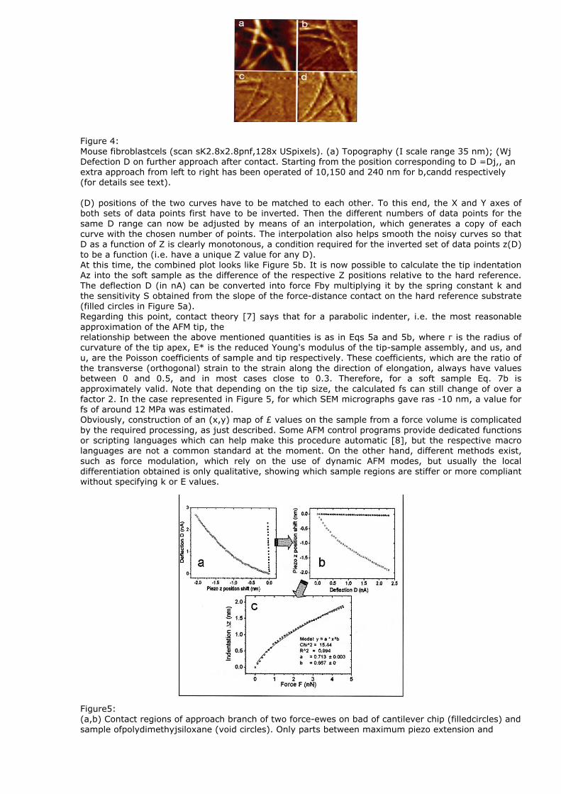
Figure 4: Mouse fibroblastcels (scan sK2.8x2.8pnf,128x USpixels). (a) Topography (I scale range 35 nm); (Wj Defection D on further approach after contact. Starting from the position corresponding to D =Dj,, an extra approach from left to right has been operated of 10,150 and 240 nm for b,candd respectively (for details see text). (D) positions of the two curves have to be matched to each other. To this end, the X and Y axes of both sets of data points first have to be inverted. Then the different numbers of data points for the same D range can now be adjusted by means of an interpolation, which generates a copy of each curve with the chosen number of points. The interpolation also helps smooth the noisy curves so that D as a function of Z is clearly monotonous, a condition required for the inverted set of data points z(D) to be a function (i.e. have a unique Z value for any D). At this time, the combined plot looks like Figure 5b. It is now possible to calculate the tip indentation Az into the soft sample as the difference of the respective Z positions relative to the hard reference. The deflection D (in nA) can be converted into force Fby multiplying it by the spring constant k and the sensitivity S obtained from the slope of the force-distance contact on the hard reference substrate (filled circles in Figure 5a). Regarding this point, contact theory [7] says that for a parabolic indenter, i.e. the most reasonable approximation of the AFM tip, the relationship between the above mentioned quantities is as in Eqs 5a and 5b, where г is the radius of curvature of the tip apex, E* is the reduced Young's modulus of the tip-sample assembly, and us, and u, are the Poisson coefficients of sample and tip respectively. These coefficients, which are the ratio of the transverse (orthogonal) strain to the strain along the direction of elongation, always have values between 0 and 0.5, and in most cases close to 0.3. Therefore, for a soft sample Eq. 7b is approximately valid. Note that depending on the tip size, the calculated fs can still change of over a factor 2. In the case represented in Figure 5, for which SEM micrographs gave ras -10 nm, a value for fs of around 12 MPa was estimated. Obviously, construction of an (x,y) map of £ values on the sample from a force volume is complicated by the required processing, as just described. Some AFM control programs provide dedicated functions or scripting languages which can help make this procedure automatic [8], but the respective macro languages are not a common standard at the moment. On the other hand, different methods exist, such as force modulation, which rely on the use of dynamic AFM modes, but usually the local differentiation obtained is only qualitative, showing which sample regions are stiffer or more compliant without specifying k or E values. Figure5: (a,b) Contact regions of approach branch of two force-ewes on bad of cantilever chip (filledcircles) and sample ofpolydimethyjsiloxane (void circles). Only parts between maximum piezo extension and

intercept with zero-level force have been selected, (s) Original plots, (b) Same plots after inverting X and Y axes, and making D range and data sam¬pling uniform, (c) Tip Mentation Az/hto tested sample surface, derived from b, plotted as a function of the applied force F, (including fit). CONCLUSIONS This tutorial has shown how to determine the forces involved in AFM measurements, and some peculiar quantities thereof (most importantly adhesion maps and individual local values of Young's modulus). The quasi-piconew-ton sensitivity of the AFM makes it possible to investigate a number of processes determined by intermolecular forces, both in the field of biomedical research (e.g. the replication of DNA, synthesis of proteins, and drug delivery) and of materials science and nanotechnology (e.g. the viscoelastic characterization of novel materials and of fundamental processes in new techniques such as soft lithography and dewetting). All of these make force-distance imaging techniques a real kind of spec-troscopy, with a bright future. REFERENCES
1. Israelachvili, ]. Intermotecular and Surface Forces, AcademicPress, London (2nd Edn), 1991. 2. Solver P47H-PRO, data sheet:
http:llntmdt.comlProductslScanningJrobe_Microscopeslproduct13.html. 3. Young, I/I/. C. Koark's formulas for stress and strain, McGraw-Hill, 6th Edn, 1991. 4. Sam/, D. Scanning force Microscopy, Oxford Series onOptical Sciences, 1991. 5. Cappella, B. and Dietler, G. Surf. Sci. Rep. 34:1,1999. 6. Revenko, I. Dl-Veeco extended application note, 2000; Ales-andrini, A. andfacci, P. Meas. Sci,
Technol. 16Щ 2005. 7. Hertz, H.J.ReineAngew. Math. 92:156, mi;Sneddon,I.N. Int. J.Eng. Sci. 3:47,1965. 8. Automated SPM measurements, NT-MDIapplication note,
2005,wm.ntmdtrulDocumentsl246jutomatedSPM.pdf
§2006 John Wiley & Sons, Ltd