Tutorial for ATENA Science GiD Construction Process
39
Červenka Consulting s.r.o. Na Hrebenkach 55 150 00 Prague Czech Republic Phone: +420 220 610 018 E-mail: [email protected] Web: http://www.cervenka.cz ATENA Program Documentation Part 4-8 ATENA Science – GiD Construction Process Tutorial Step by step guide for modeling construction process with ATENA and GiD Written by Tereza Sajdlová Prague, May 5, 2016
Transcript of Tutorial for ATENA Science GiD Construction Process
Červenka Consulting s.r.o. Na Hrebenkach 55 150 00 Prague Czech Republic Phone: +420 220 610 018 E-mail: [email protected] Web: http://www.cervenka.cz
ATENA Program Documentation Part 4-8 ATENA Science – GiD Construction Process Tutorial Step by step guide for modeling construction
process with ATENA and GiD
Written by
Tereza Sajdlová
Prague, May 5, 2016

Trademarks:
ATENA is registered trademark of Vladimir Cervenka.
GiD is registered trademark of CIMNE of Barcelona, Spain.
Microsoft and Microsoft Windows are registered trademarks of Microsoft Corporation.
Other names may be trademarks of their respective owners.
Copyright © 2015-2016 Červenka Consulting s.r.o.

ATENA Science – Construction Process Tutorial i
CONTENTS
1. INTRODUCTION ............................................................................................................ 1
2. BRIEF OVERVIEW.......................................................................................................... 2
3. MODEL DESCRIPTION ................................................................................................... 4 3.1 Model Geometry ............................................................................................................................. 5
4. CONSTRUCTION PROCESS.............................................................................................. 9 4.1 Material Definition ......................................................................................................................... 9
4.1.1. Shell elements ....................................................................................................................................................... 10 4.1.2. Prestressed cables and reinforcement bars ................................................................................................ 16
4.2 Load Definition ............................................................................................................................. 22 4.2.1. Interval no.1 – casting phase CP0................................................................................................................... 22 4.2.2. Interval no.2 – casting phase CP1................................................................................................................... 24 4.2.3. Interval no.3 – casting phase CP2................................................................................................................... 27 4.2.4. Interval no.4 – loading by casting vehicle ................................................................................................... 28 4.2.5. Interval no.5 – loading up to the failure ....................................................................................................... 30
5. CALCULATION ........................................................................................................... 32
6. CONCLUSION............................................................................................................. 33
7. PROGRAM DISTRIBUTORS AND DEVELOPERS.................................................................. 34
8. LITERATURE .............................................................................................................. 35


ATENA Science – Construction Process Tutorial 1
1. INTRODUCTION In many cases (bridges, multi-storey buildings), it is important to analyze structure not as a whole but to consider its construction process. Structure is gradually loaded in accordance with construction. At the end of construction, the structure is exposed to the given combination of the load cases until it reaches its ultimate limit state.
ATENA software in combination with GiD provides possibility to model construction process of different structures. ATENA-GiD is a finite element based software system specifically developed for the nonlinear analysis of reinforced concrete structures. This tutorial contains a step by step explanation on how to model construction process of the bridge similar to Figure 1 using the programs ATENA and GiD.
Tutorial is targeted for intermediate ATENA-GiD users who have already finished the basic ATENA and GiD tutorial. The preparation of the model is not described in detail, as it can be done according to the basic ATENA-GiD tutorial. This document is focused just on the construction process.
Figure 1: Bridge construction
2
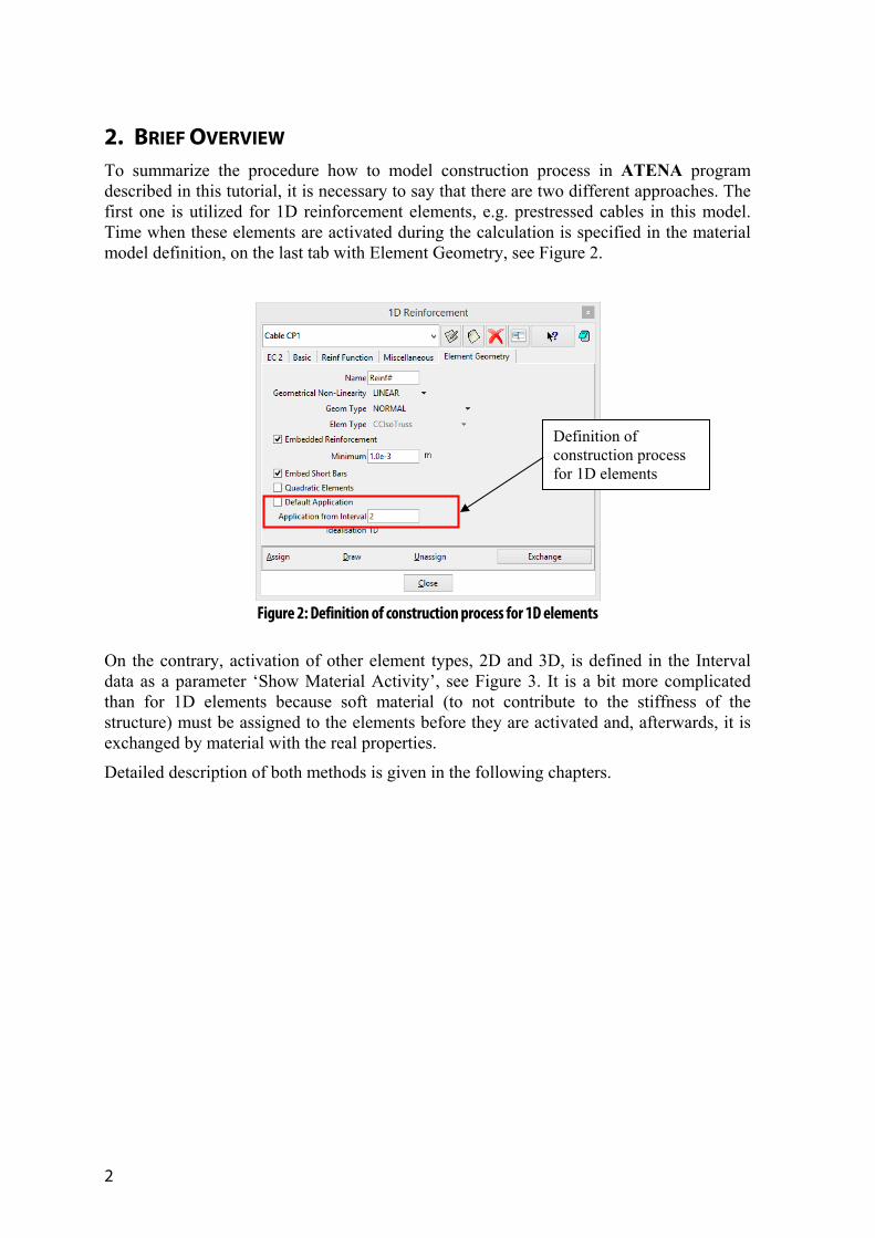
2. BRIEF OVERVIEW To summarize the procedure how to model construction process in ATENA program described in this tutorial, it is necessary to say that there are two different approaches. The first one is utilized for 1D reinforcement elements, e.g. prestressed cables in this model. Time when these elements are activated during the calculation is specified in the material model definition, on the last tab with Element Geometry, see Figure 2.
Figure 2: Definition of construction process for 1D elements
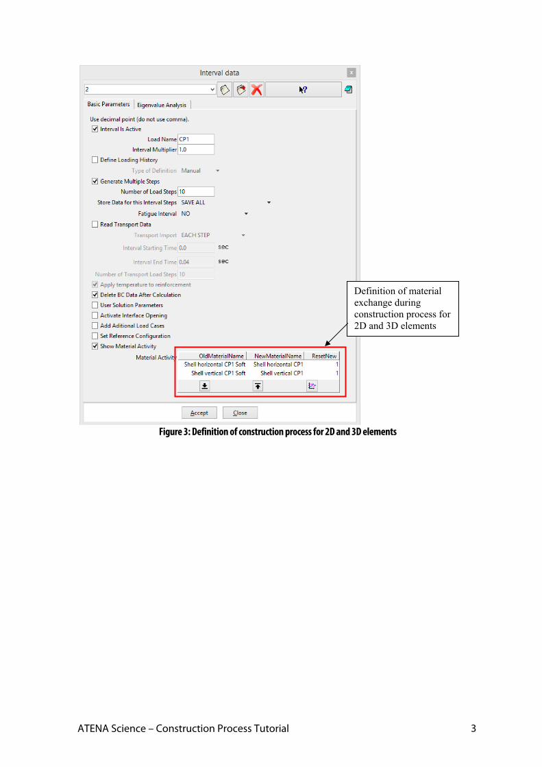
On the contrary, activation of other element types, 2D and 3D, is defined in the Interval data as a parameter ‘Show Material Activity’, see Figure 3. It is a bit more complicated than for 1D elements because soft material (to not contribute to the stiffness of the structure) must be assigned to the elements before they are activated and, afterwards, it is exchanged by material with the real properties.
Detailed description of both methods is given in the following chapters.
Definition of construction process for 1D elements
ATENA Science – Construction Process Tutorial 3
Figure 3: Definition of construction process for 2D and 3D elements
Definition of material exchange during construction process for 2D and 3D elements
4
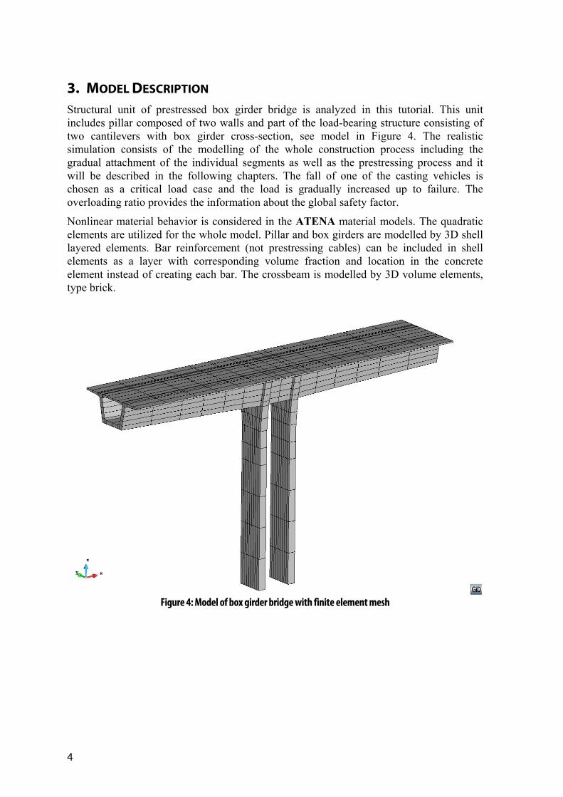
3. MODEL DESCRIPTION Structural unit of prestressed box girder bridge is analyzed in this tutorial. This unit includes pillar composed of two walls and part of the load-bearing structure consisting of two cantilevers with box girder cross-section, see model in Figure 4. The realistic simulation consists of the modelling of the whole construction process including the gradual attachment of the individual segments as well as the prestressing process and it will be described in the following chapters. The fall of one of the casting vehicles is chosen as a critical load case and the load is gradually increased up to failure. The overloading ratio provides the information about the global safety factor.
Nonlinear material behavior is considered in the ATENA material models. The quadratic elements are utilized for the whole model. Pillar and box girders are modelled by 3D shell layered elements. Bar reinforcement (not prestressing cables) can be included in shell elements as a layer with corresponding volume fraction and location in the concrete element instead of creating each bar. The crossbeam is modelled by 3D volume elements, type brick.
Figure 4: Model of box girder bridge with finite element mesh

ATENA Science – Construction Process Tutorial 5
3.1 Model Geometry Geometry of the model is prepared in the file: %Public%\ Documents\ATENA Examples\Science\GiD\Tutorial.ConstructionProcess3D\Bridge_ConstructionProcess_3D.gid that can be opened by selecting Files | Open in GiD. User must have installed programs GiD and ATENA to start nonlinear analysis using the ATENA-GiD system. If you do not have installed the above mentioned programs yet, you can install them following the instructions from the ATENA-GiD manual [2].
The prepared model contains geometry of the structural unit of the bridge and finite element mesh as shown in Figure 4. The model is divided into individual parts to create nice mesh. If we look at the cross-section of the bridge, it consists of 18 parts, see Figure 5. All parts are quadrilateral in order to achieve prismatic volume in 3D. Each volume has common surface with the adjacent volume. It means that there is no need to model fixed contacts (Master-Slave) between individual elements. The only fixed contact is between the box girder and pillars, see Figure 6.
Figure 5: Cross-section of the model
Figure 6: Fixed contacts between pillars and box girder
6
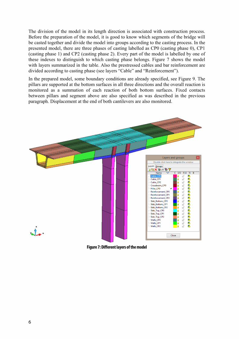
The division of the model in its length direction is associated with construction process. Before the preparation of the model, it is good to know which segments of the bridge will be casted together and divide the model into groups according to the casting process. In the presented model, there are three phases of casting labelled as CP0 (casting phase 0), CP1 (casting phase 1) and CP2 (casting phase 2). Every part of the model is labelled by one of these indexes to distinguish to which casting phase belongs. Figure 7 shows the model with layers summarized in the table. Also the prestressed cables and bar reinforcement are divided according to casting phase (see layers “Cable” and “Reinforcement”).
In the prepared model, some boundary conditions are already specified, see Figure 9. The pillars are supported at the bottom surfaces in all three directions and the overall reaction is monitored as a summation of each reaction of both bottom surfaces. Fixed contacts between pillars and segment above are also specified as was described in the previous paragraph. Displacement at the end of both cantilevers are also monitored.
Figure 7: Different layers of the model

ATENA Science – Construction Process Tutorial 7
Figure 8: Prestressed cables and bar reinforcement
Figure 9: Prepared boundary conditions
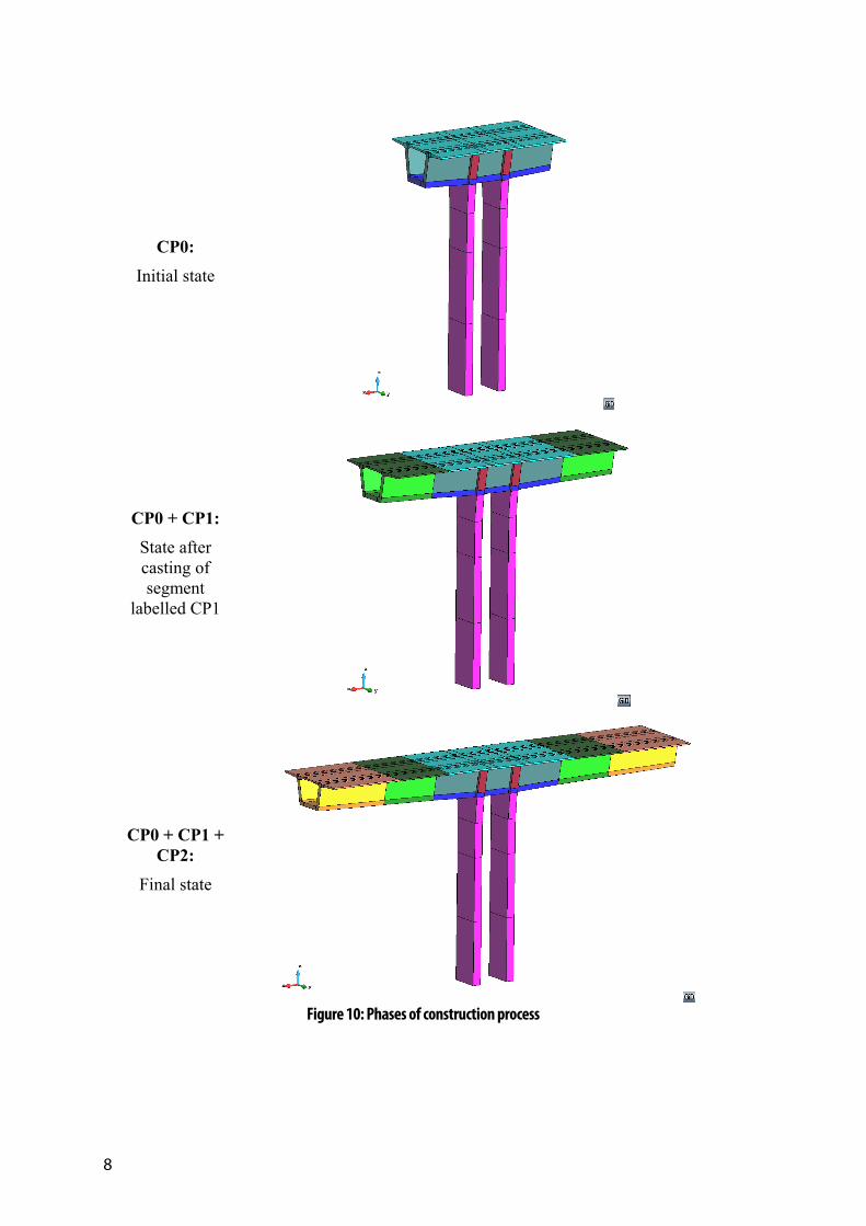
In the following chapters the construction process of the bridge structural unit will be described. It consists of three phases shown in Figure 10. In the first phase, the pillar, the segment above and the first part of cantilevers are casted (see first picture in Figure 10) and loaded by its self-weight. The cables passing through this part of bridge are prestressed. The second phase includes casting of the next part of segment labelled “CP1” and prestressing of corresponding cables. During the third stage, the structural unit is finished and the last part of the segment (CP2) is casted and prestressed.
After the construction process, the structure is loaded by the casting vehicle just at one side to simulate the fall of the second vehicle. This load is gradually increased up to the failure.
Fixed contact (Master-Slave) Monitor for
displacement
Monitor for displacement
Supports and monitor for reaction
8
CP0:
Initial state
CP0 + CP1:
State after casting of segment
labelled CP1
CP0 + CP1 + CP2:
Final state
Figure 10: Phases of construction process
ATENA Science – Construction Process Tutorial 9
4. CONSTRUCTION PROCESS This chapter contains a step by step explanation how to define construction process in the model created in ATENA-GiD software. Definition of materials is described in the first part of the chapter. Loading as a self-weight of concrete or casting vehicle and prestressing of cables is defined in the second part.
Gradual casting of bridge segments is defined by exchange of materials during the interval specification. User have to prepare material model for concrete and model for soft material that is used for the segments before they are casted. All the segments are in the model throughout whole calculation. At the time they are casted, only the material properties are changed. Before casting, these elements have very low Young´s modulus and they do not contribute to the structural stiffness. Displacements of the finite element nodes follow the deflection of the already casted part which is in good accordance with the expected behavior. After the casting of the next part of the bridge, corresponding elements are removed and added again with the new material properties.
Gradual prestressing of cables is created in different way. In the material model for reinforcement, the user can choose from which interval the reinforcement will be applied.
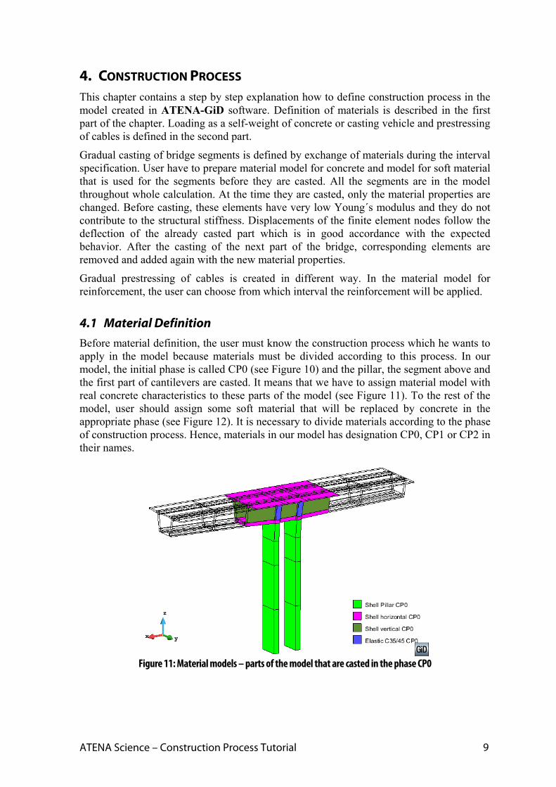
4.1 Material Definition Before material definition, the user must know the construction process which he wants to apply in the model because materials must be divided according to this process. In our model, the initial phase is called CP0 (see Figure 10) and the pillar, the segment above and the first part of cantilevers are casted. It means that we have to assign material model with real concrete characteristics to these parts of the model (see Figure 11). To the rest of the model, user should assign some soft material that will be replaced by concrete in the appropriate phase (see Figure 12). It is necessary to divide materials according to the phase of construction process. Hence, materials in our model has designation CP0, CP1 or CP2 in their names.
Figure 11: Material models – parts of the model that are casted in the phase CP0

10
Figure 12: Material models – parts of the model that will be casted in following phases
4.1.1. Shell elements
Shell layered elements are used for the concrete parts as pillars and the segments. Only elastic crossbeam is made of volume elements. There are three types of shell materials in our model, first one is utilized for pillars, the second for horizontal parts of the segments and third for vertical parts. The shell materials must be divided due to the different orientation of local coordinate system and different thickness. However, the base material for shell elements should be the same because the whole structure is made of concrete corresponding to strength class C35/45. User must prepare this material in ATENA-GiD program.
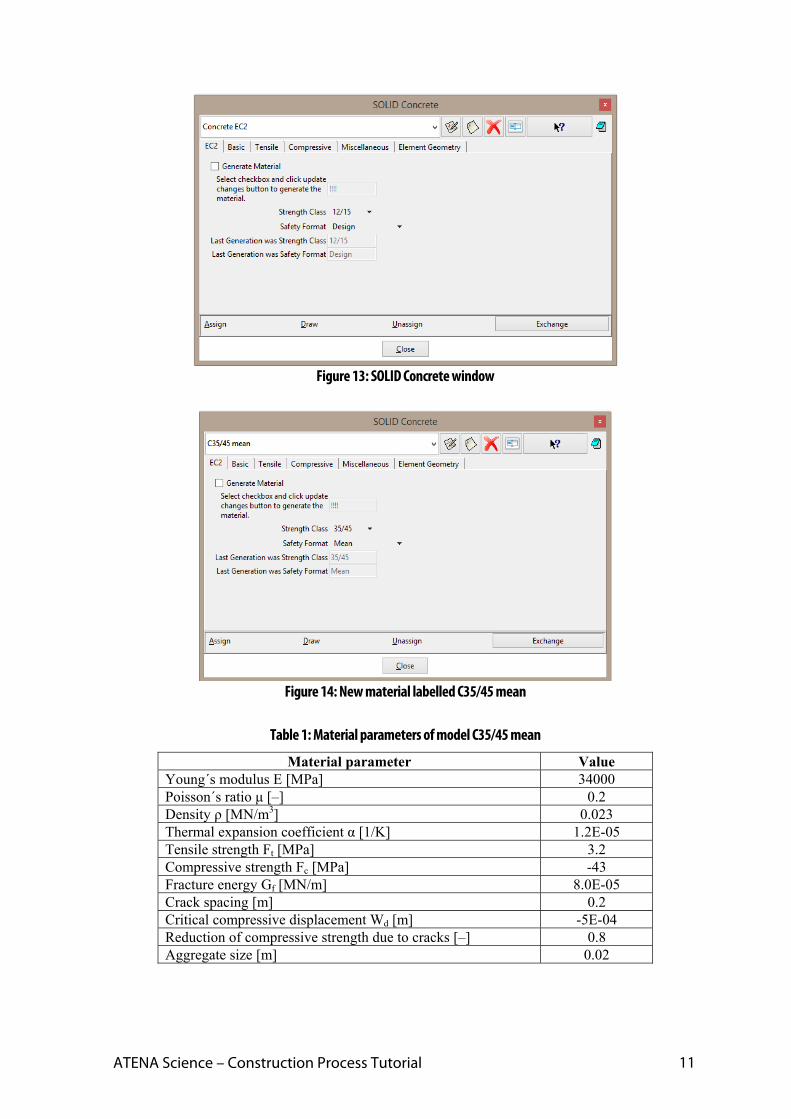
The input for SOLID Concrete material should be opened by clicking on the icon . Afterwards, window for generating the material will appear, see Figure 13. The model labelled Concrete EC2 will be used. The new material based on Concrete EC2 can be
created by clicking on the icon , the new name can be C35/45 mean and then it can be modified according to the user´s needs. On the first tab the class “35/45” and format “Mean” should be chosen. By selecting checkbox “Generate material” and clicking the
button (“update changes”), the material will be generated. Generated material parameters are summarized in Table 1.
ATENA Science – Construction Process Tutorial 11
Figure 13: SOLID Concrete window
Figure 14: New material labelled C35/45 mean
Table 1: Material parameters of model C35/45 mean
Material parameter Value Young´s modulus E [MPa] 34000 Poisson´s ratio μ [–] 0.2 Density ρ [MN/m3] 0.023 Thermal expansion coefficient α [1/K] 1.2E-05 Tensile strength Ft [MPa] 3.2 Compressive strength Fc [MPa] -43 Fracture energy Gf [MN/m] 8.0E-05 Crack spacing [m] 0.2 Critical compressive displacement Wd [m] -5E-04 Reduction of compressive strength due to cracks [–] 0.8 Aggregate size [m] 0.02

12
After the generation of the base material, material model for shell elements must be
prepared and it can be done by clicking on the icon . Using the same icon as was described in the previous paragraph, the new shell material will be created. At first, it is possible to make material for pillars so the material is called Shell Pillar CP0. The local coordinate system must be modified according to the orientation of shell elements. Local Z axis should be perpendicular to the plane of the shell element as it is presented in the blue part of the Figure 15. It means that local axis Z must be equal to global axis X in case of the pillars that’s why vector (1;0;0) is used for the definition of local Z. Local axis X can be define manually or automatic detection can be utilized. In this case, we chose definition by vector. The local axis X goes against the direction of global axis Z. Manual definiton of local axis X is important in the case when there are more shell elements with different orientation and user wants to have the same orientation of the X axis in shell elements.
Figure 15: Definition of shell local coordinate system
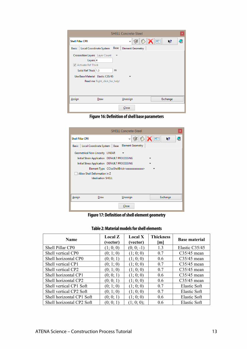
Other shell parameters are specified in tab ‘Base’, see Figure 16. User must enter the number of layers (4 layers are used in this calculation) and reference thickness which should be absolute thickness or average of variable thickness. It does not have to be specified. Afterwards, the actual shell thickness in integration points is used instead. Finally, the base material must be chosen on this tab, it is elastic material labelled Elastic C35/45 for pillars. Pillars are modelled by elastic material because the damage is expected at the upper part of the bridge, not at the pillars. The last tab is dedicated to element geometry (see Figure 17). Default settings of all parameters will be used.
According to the described properties in the previous paragraphs, other shell materials must be prepared. It is necessary to create materials that are divided by phases of construction process. Before the part of the model is casted, it is made of some soft material so user has to prepare also this type of material. All shell materials that are used in the model are summarized in Table 2. Parameters that varies between each models are shown, other parameters are the same as in the model ‘Shell Pillar CP0’ that was described before in more detail (see Figure 16 and Figure 17).
ATENA Science – Construction Process Tutorial 13
Figure 16: Definition of shell base parameters
Figure 17: Definition of shell element geometry
Table 2: Material models for shell elements
Name Local Z (vector)
Local X (vector)
Thickness [m]
Base material
Shell Pillar CP0 (1; 0; 0) (0; 0; -1) 1.3 Elastic C35/45 Shell vertical CP0 (0; 1; 0) (1; 0; 0) 0.7 C35/45 mean Shell horizontal CP0 (0; 0; 1) (1; 0; 0) 0.6 C35/45 mean Shell vertical CP1 (0; 1; 0) (1; 0; 0) 0.7 C35/45 mean Shell vertical CP2 (0; 1; 0) (1; 0; 0) 0.7 C35/45 mean Shell horizontal CP1 (0; 0; 1) (1; 0; 0) 0.6 C35/45 mean Shell horizontal CP2 (0; 0; 1) (1; 0; 0) 0.6 C35/45 mean Shell vertical CP1 Soft (0; 1; 0) (1; 0; 0) 0.7 Elastic Soft Shell vertical CP2 Soft (0; 1; 0) (1; 0; 0) 0.7 Elastic Soft Shell horizontal CP1 Soft (0; 0; 1) (1; 0; 0) 0.6 Elastic Soft Shell horizontal CP2 Soft (0; 0; 1) (1; 0; 0); 0.6 Elastic Soft

14
Parameters of elastic material ‘Elastic C35/45’ and ‘Elastic Soft’, which are used as a base material for some shell elements, are shown in the Table 3 and Table 4. ‘Elastic C35/45’ replaces nonlinear concrete in the pillars hence the parameters correspond to concrete C35/45. Material ‘Elastic Soft’ is applied in the parts of the bridge before they are casted in casting phase CP1 and CP2. Young´s modulus is very low, 10 MPa, and other parameters correspond to concrete C35/45.
Table 3: Material parameters of model Elastic C35/45
Material parameter Value Young´s modulus E [MPa] 34000 Poisson´s ratio μ [–] 0.2 Density ρ [MN/m3] 0.023 Thermal expansion coefficient α [1/K] 1.2E-05
Table 4: Material parameters of model Elastic Soft
Material parameter Value Young´s modulus E [MPa] 10 Poisson´s ratio μ [–] 0.2 Density ρ [MN/m3] 0.023 Thermal expansion coefficient α [1/K] 1.2E-05
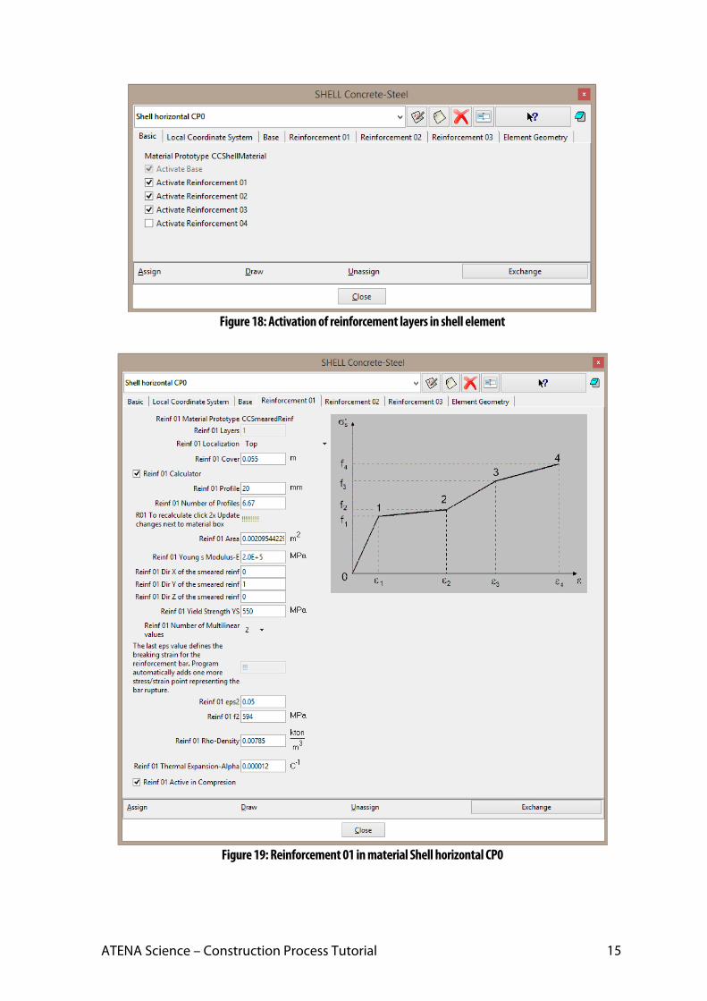
Shell models with concrete as a base material should be reinforced by ordinary reinforcement. It can be done by separate bars but it is favorable to insert reinforcement directly in shell material which is less time-consuming. On the first tab ‘Basic’ reinforcement must be activated. In presented model, three different types of reinforcement are used, see Figure 18. Definition of the first type is depicted in Figure 19. Position, reinforcement cover, area and material properties are specified here. ‘Reinforcement 01’ is top reinforcement in direction Y with cover 55 mm. The area should be calculated per unit length and it corresponds to bars with diameter 20 mm with distance 150 mm between each bar.
Other types of reinforcement vary in position, cover and area and they are summarized in Table 6. Material parameters presented in Table 5 are the same for every reinforcement in shell elements.
ATENA Science – Construction Process Tutorial 15
Figure 18: Activation of reinforcement layers in shell element
Figure 19: Reinforcement 01 in material Shell horizontal CP0

16
Table 5: Material parameters of reinforcement in shell elements
Material parameter Value Young´s modulus E [MPa] 200000 Yield strength [MPa] 550 Ultimate strength [MPa] 594 Strain at ultimate strength [-] 0.05 Density ρ [MN/m3] 0.0785 Thermal expansion coefficient α [1/K] 1.2E-05
Table 6: Reinforcement in shell elements
Name Reinforcement 01 Reinforcement 02 Reinforcement 03 Shell vertical CP0 Shell vertical CP1 Shell vertical CP2
Top, Direction Y Cover 55 mm
Area 0.002095 m2
Bottom, Direction Y Cover 55 mm
Area 0.001027 m2
Top and Bottom, Dir. X Cover 75 mm
Area 0.001341 m2
Shell horizontal CP0 Top, Direction Y
Cover 55 mm Area 0.002095 m2
Bottom, Direction Y Cover 55 mm
Area 0.002095 m2
Top and Bottom, Dir. X Cover 75 mm
Area 0.005890 m2
Shell horizontal CP1 Top, Direction Y
Cover 55 mm Area 0.002095 m2
Bottom, Direction Y Cover 55 mm
Area 0.001027 m2
Top and Bottom, Dir. X Cover 75 mm
Area 0.003142 m2
Shell horizontal CP2 Top, Direction Y
Cover 55 mm Area 0.002095 m2
Bottom, Direction Y Cover 55 mm
Area 0.001027 m2
Top and Bottom, Dir. X Cover 75 mm
Area 0.001341 m2
4.1.2. Prestressed cables and reinforcement bars
Prestressed cables and reinforcement bars are labelled in the same way as shell elements described in the previous chapter, i.e. according to construction phase in which they should be activated. Cables and bars activated during construction phase CP0 are shown in the Figure 20 and the rest of the reinforcement applied in the following phases CP1 and CP2 is in Figure 21.
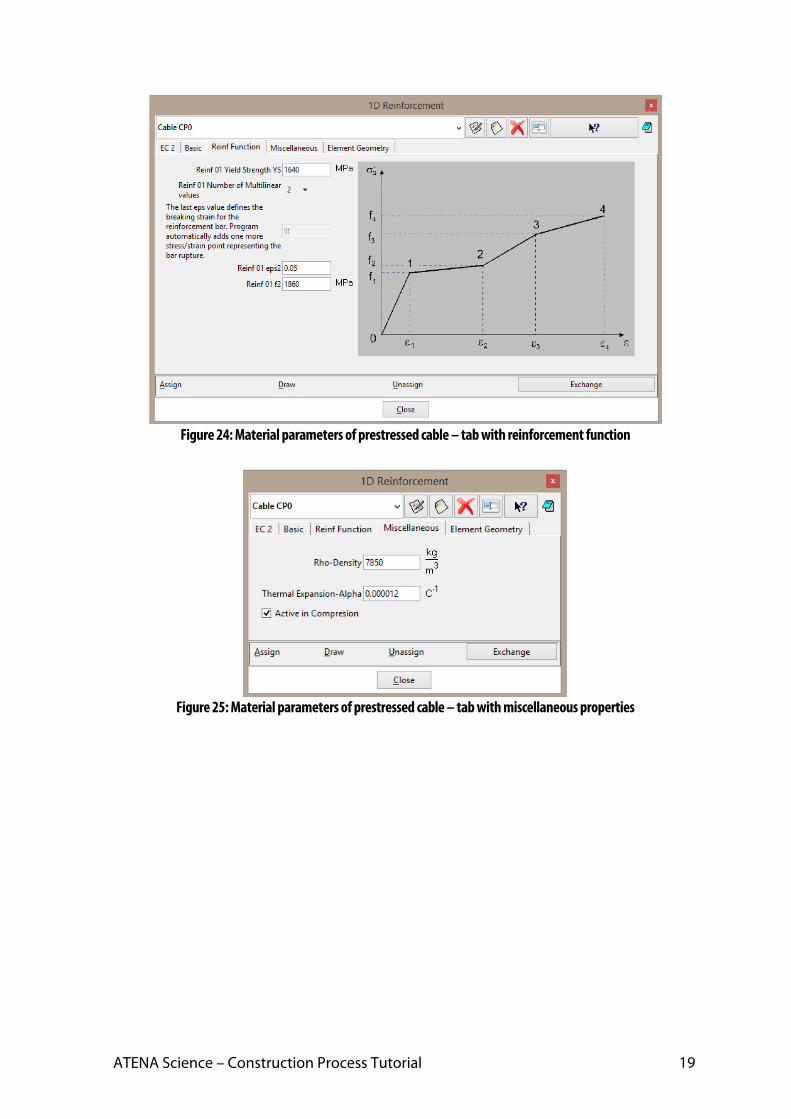
Material characteristics for cables are depicted in the Figure 22 to Figure 26 and parameters for bars can be found in the Figure 27 to Figure 30. Young´s modulus of cables is 195 GPa and yield strength is 1640 MPa. One cable consists of 18 profiles with diameter 25 mm. Bar reinforcement has Young´s modulus 200 GPa, yield strength 550 MPa and diameter 16 mm.
As a contrary to the concrete parts, here is special material property that allows us to define the construction process directly in the material model. This property is on the tab ‘Element geometry’, see Figure 26, and it is called ‘Application from Interval’. Cables and bars that belong to the initial construction phase CP0 should be applied from the interval 1 (Default Application). For reinforcement activated in construction phase CP1, the checkbox Default application cannot be selected and Application from Interval 2 must be used instead. The Application from Interval 3 is used for the reinforcement activated in CP2 as well.
All the prestressed cables have the same parameters and differ only in the Application from Interval as well as reinforcement bars.

ATENA Science – Construction Process Tutorial 17
Figure 20: Cables and reinforcement that are activated in the first interval (phase CP0)
Figure 21: Cables and reinforcement that are activated in the following intervals (phase CP1 and CP2)

18
Figure 22: Material parameters of prestressed cable – tab with properties according to EC 2
Figure 23: Material parameters of prestressed cable – tab with basic properties
ATENA Science – Construction Process Tutorial 19
Figure 24: Material parameters of prestressed cable – tab with reinforcement function
Figure 25: Material parameters of prestressed cable – tab with miscellaneous properties

20
Figure 26: Material parameters of prestressed cable – tab with element geometry
Figure 27: Material parameters of reinforcement – tab with basic properties
ATENA Science – Construction Process Tutorial 21
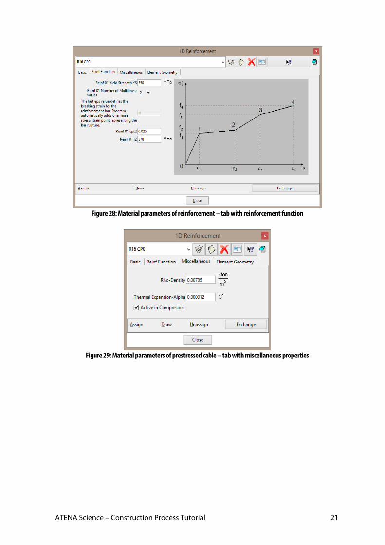
Figure 28: Material parameters of reinforcement – tab with reinforcement function
Figure 29: Material parameters of prestressed cable – tab with miscellaneous properties
22
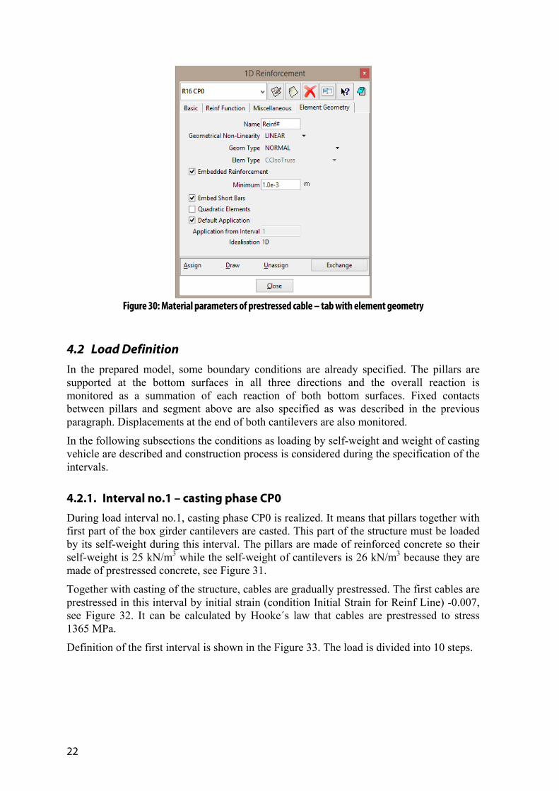
Figure 30: Material parameters of prestressed cable – tab with element geometry
4.2 Load Definition In the prepared model, some boundary conditions are already specified. The pillars are supported at the bottom surfaces in all three directions and the overall reaction is monitored as a summation of each reaction of both bottom surfaces. Fixed contacts between pillars and segment above are also specified as was described in the previous paragraph. Displacements at the end of both cantilevers are also monitored.
In the following subsections the conditions as loading by self-weight and weight of casting vehicle are described and construction process is considered during the specification of the intervals.
4.2.1. Interval no.1 – casting phase CP0
During load interval no.1, casting phase CP0 is realized. It means that pillars together with first part of the box girder cantilevers are casted. This part of the structure must be loaded by its self-weight during this interval. The pillars are made of reinforced concrete so their self-weight is 25 kN/m3 while the self-weight of cantilevers is 26 kN/m3 because they are made of prestressed concrete, see Figure 31.
Together with casting of the structure, cables are gradually prestressed. The first cables are prestressed in this interval by initial strain (condition Initial Strain for Reinf Line) -0.007, see Figure 32. It can be calculated by Hooke´s law that cables are prestressed to stress 1365 MPa.
Definition of the first interval is shown in the Figure 33. The load is divided into 10 steps.

ATENA Science – Construction Process Tutorial 23
Figure 31: Self-weight applied on the elements casted during construction phase CP0
Figure 32: Cables prestressed during construction phase CP0

24
Figure 33: Definition of interval no. 1
4.2.2. Interval no.2 – casting phase CP1
The second interval ‘CP1’ contains casting of the other segments of box girder bridge according to casting of the real structures shown in Figure 34. These segments are loaded by their self-weight together with prestressing of cables passing through this part, see Figure 35 and Figure 36.
At this time, it is important to define exchange of materials in the segments that are casted during this interval CP1. Initial soft material must be replaced by concrete. This is done by selecting checkbox ‘Show Material Activity’ at the tab with interval definition, see Figure 37. When the checkbox is selected, the table with material activity appears. In the first column, user have to type name of the material that should be replaced and, in the second column, name of the new material that will be used instead of initial material. The third column is labelled ‘ResetNew’ and it should contain value 0 or 1. Value 1 means that all internal forces in elements, where materials are replaced, will be reset.
The second interval contains 10 steps.

ATENA Science – Construction Process Tutorial 25
Figure 34: Construction process of box girder bridge
Figure 35: Self-weight applied on the elements casted during construction phase CP1
26
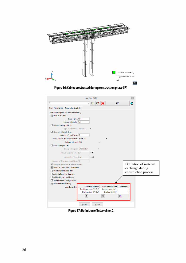
Figure 36: Cables prestressed during construction phase CP1
Figure 37: Definition of interval no. 2
Definition of material exchange during construction process
ATENA Science – Construction Process Tutorial 27
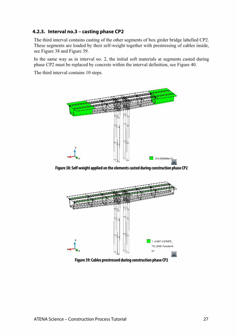
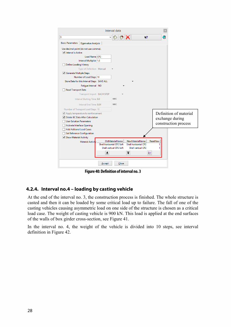
4.2.3. Interval no.3 – casting phase CP2
The third interval contains casting of the other segments of box girder bridge labelled CP2. These segments are loaded by their self-weight together with prestressing of cables inside, see Figure 38 and Figure 39.
In the same way as in interval no. 2, the initial soft materials at segments casted during phase CP2 must be replaced by concrete within the interval definition, see Figure 40.
The third interval contains 10 steps.
Figure 38: Self-weight applied on the elements casted during construction phase CP2
Figure 39: Cables prestressed during construction phase CP2
28
Figure 40: Definition of interval no. 3
4.2.4. Interval no.4 – loading by casting vehicle
At the end of the interval no. 3, the construction process is finished. The whole structure is casted and then it can be loaded by some critical load up to failure. The fall of one of the casting vehicles causing asymmetric load on one side of the structure is chosen as a critical load case. The weight of casting vehicle is 900 kN. This load is applied at the end surfaces of the walls of box girder cross-section, see Figure 41.
In the interval no. 4, the weight of the vehicle is divided into 10 steps, see interval definition in Figure 42.
Definition of material exchange during construction process

ATENA Science – Construction Process Tutorial 29
Figure 41: Loading by the casting vehicle
Figure 42: Definition of interval no. 4
30
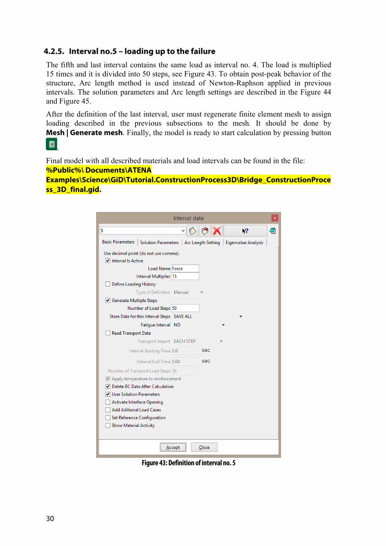
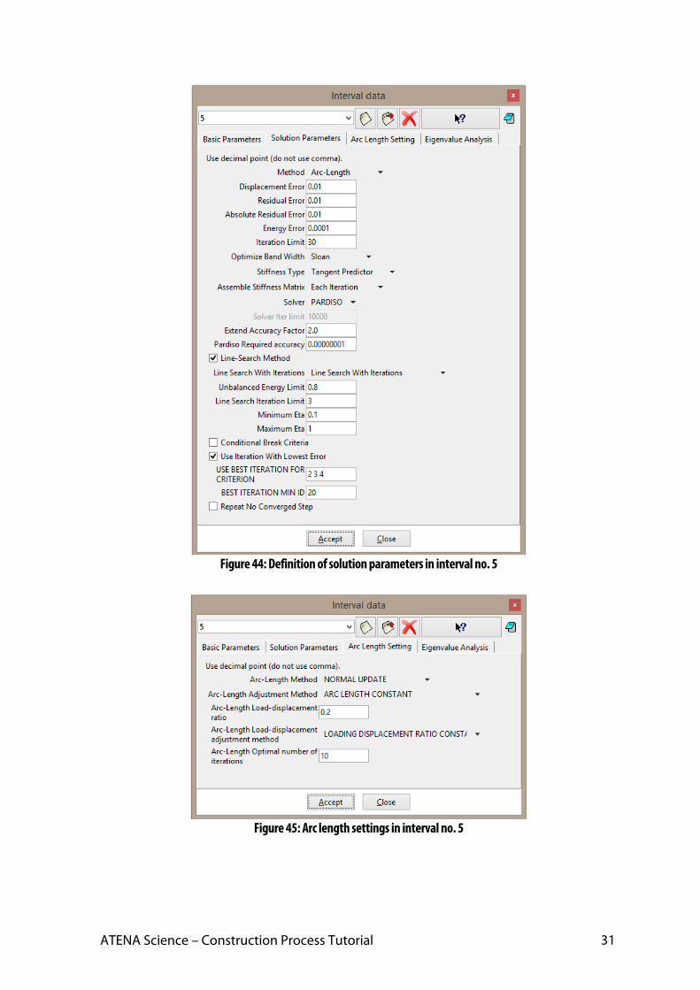
4.2.5. Interval no.5 – loading up to the failure
The fifth and last interval contains the same load as interval no. 4. The load is multiplied 15 times and it is divided into 50 steps, see Figure 43. To obtain post-peak behavior of the structure, Arc length method is used instead of Newton-Raphson applied in previous intervals. The solution parameters and Arc length settings are described in the Figure 44 and Figure 45.
After the definition of the last interval, user must regenerate finite element mesh to assign loading described in the previous subsections to the mesh. It should be done by Mesh | Generate mesh. Finally, the model is ready to start calculation by pressing button
.
Final model with all described materials and load intervals can be found in the file: %Public%\ Documents\ATENA Examples\Science\GiD\Tutorial.ConstructionProcess3D\Bridge_ConstructionProcess_3D_final.gid.
Figure 43: Definition of interval no. 5
ATENA Science – Construction Process Tutorial 31
Figure 44: Definition of solution parameters in interval no. 5
Figure 45: Arc length settings in interval no. 5

32
5. CALCULATION After the material and interval definition described in previous chapters, the calculation is started and user can control load displacement diagram, deformed shape and for example crack widths during the calculation, see Figure 46.
Figure 46: Running calculation

ATENA Science – Construction Process Tutorial 33
6. CONCLUSION This tutorial provides a step by step instructions how to model construction process in ATENA-GiD interface. Different methods are applied for gradual casting of individual segments and for prestressing of the cables. Gradual casting is modelled by exchange of materials specified during the interval definition while the gradual prestressing is defined as a parameter in the material model.
For more information about the program the user should consult the ATENA documentation (e.g. [1], [2], [4] or [4]) or contact the program distributor or developers. Our team is ready to answer your questions and help you to resolve your problems.

34
7. PROGRAM DISTRIBUTORS AND DEVELOPERS
Program developer: Červenka Consulting s.r.o.
Na Hrebenkach 55, 150 00 Prague 5, Czech Republic
phone: +420 220 610 018
fax: +420 220 612 227
website: www.cervenka.cz
email: [email protected]
The current list of our distributors can be found on our websites: http://www.cervenka.cz/company/distributors/

ATENA Science – Construction Process Tutorial 35
8. LITERATURE
[1] ATENA Program Documentation, Part 4-6, ATENA Science – GiD Tutorial, CERVENKA CONSULTING, 2016
[2] ATENA Program Documentation, Part 8, User’s Manual for ATENA-GiD Interface, CERVENKA CONSULTING, 2015
[3] ATENA Program Documentation, Part 12, User’s Manual for ATENA Studio, CERVENKA CONSULTING, 2016
[4] ATENA Program Documentation, Part 1, ATENA Theory Manual, CERVENKA CONSULTING, 2015
[5] ATENA Program Documentation, Part 11, ATENA Troubleshooting Manual, CERVENKA CONSULTING, 2016
[6] fib Model Code 2010 - Final draft, Volume 1., Lausanne: International Federation for Structural Concrete (fib), 2012