Tutorial: Calculation of a planetary gear train - MESYS · Tutorial: Calculation of a planetary...
11
Tutorial: Calculation of a planetary gear train This tutorial shows the usage of MESYS shaft calculation with shaft systems. A two-stage planetary gear stage is defined using the program. Please start with the tutorial for shaft calculation to see how to introduce geometry and supports for single shafts. The model is built in two steps. In the first step, only one planetary stage is build, in the second step the second planetary stage is added. As this tutorial should be easy to use, shaft geometry and gear data is kept as simple as possible. System Data We do not need to change anything on the first page for system data.
Transcript of Tutorial: Calculation of a planetary gear train - MESYS · Tutorial: Calculation of a planetary...

Tutorial: Calculation of a planetary gear train
This tutorial shows the usage of MESYS shaft calculation with shaft systems. A two-stage planetary
gear stage is defined using the program. Please start with the tutorial for shaft calculation to see how
to introduce geometry and supports for single shafts.
The model is built in two steps. In the first step, only one planetary stage is build, in the second step
the second planetary stage is added. As this tutorial should be easy to use, shaft geometry and gear
data is kept as simple as possible.
System Data
We do not need to change anything on the first page for system data.
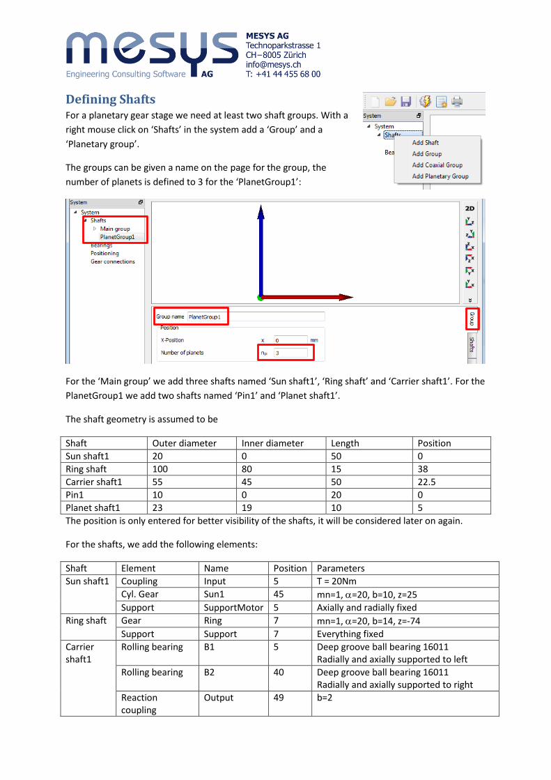
Defining Shafts For a planetary gear stage we need at least two shaft groups. With a
right mouse click on ‘Shafts’ in the system add a ‘Group’ and a
‘Planetary group’.
The groups can be given a name on the page for the group, the
number of planets is defined to 3 for the ‘PlanetGroup1’:
For the ‘Main group’ we add three shafts named ‘Sun shaft1’, ‘Ring shaft’ and ‘Carrier shaft1’. For the
PlanetGroup1 we add two shafts named ‘Pin1’ and ‘Planet shaft1’.
The shaft geometry is assumed to be
Shaft Outer diameter Inner diameter Length Position
Sun shaft1 20 0 50 0
Ring shaft 100 80 15 38
Carrier shaft1 55 45 50 22.5
Pin1 10 0 20 0
Planet shaft1 23 19 10 5
The position is only entered for better visibility of the shafts, it will be considered later on again.
For the shafts, we add the following elements:
Shaft Element Name Position Parameters
Sun shaft1 Coupling Input 5 T = 20Nm
Cyl. Gear Sun1 45 mn=1, =20, b=10, z=25
Support SupportMotor 5 Axially and radially fixed
Ring shaft Gear Ring 7 mn=1, =20, b=14, z=-74
Support Support 7 Everything fixed
Carrier shaft1
Rolling bearing B1 5 Deep groove ball bearing 16011 Radially and axially supported to left
Rolling bearing B2 40 Deep groove ball bearing 16011 Radially and axially supported to right
Reaction coupling
Output 49 b=2
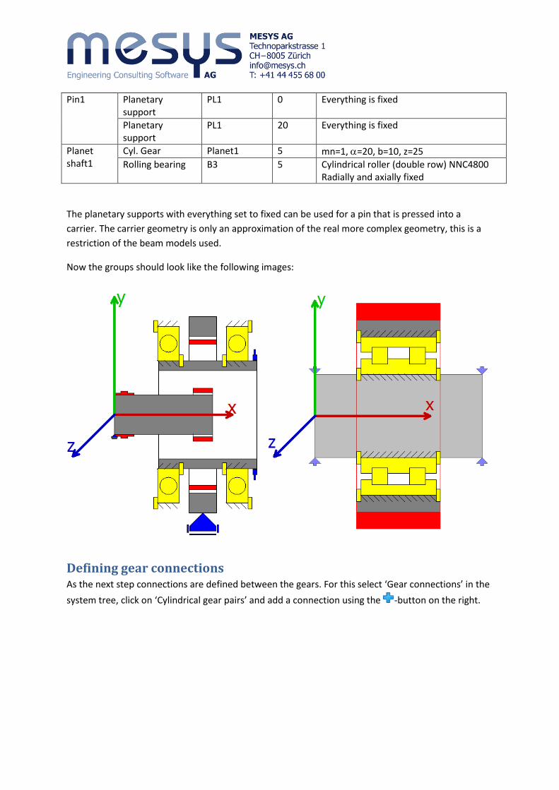
Pin1 Planetary support
PL1 0 Everything is fixed
Planetary support
PL1 20 Everything is fixed
Planet shaft1
Cyl. Gear Planet1 5 mn=1, =20, b=10, z=25
Rolling bearing B3 5 Cylindrical roller (double row) NNC4800 Radially and axially fixed
The planetary supports with everything set to fixed can be used for a pin that is pressed into a
carrier. The carrier geometry is only an approximation of the real more complex geometry, this is a
restriction of the beam models used.
Now the groups should look like the following images:
Defining gear connections As the next step connections are defined between the gears. For this select ‘Gear connections’ in the
system tree, click on ‘Cylindrical gear pairs’ and add a connection using the -button on the right.
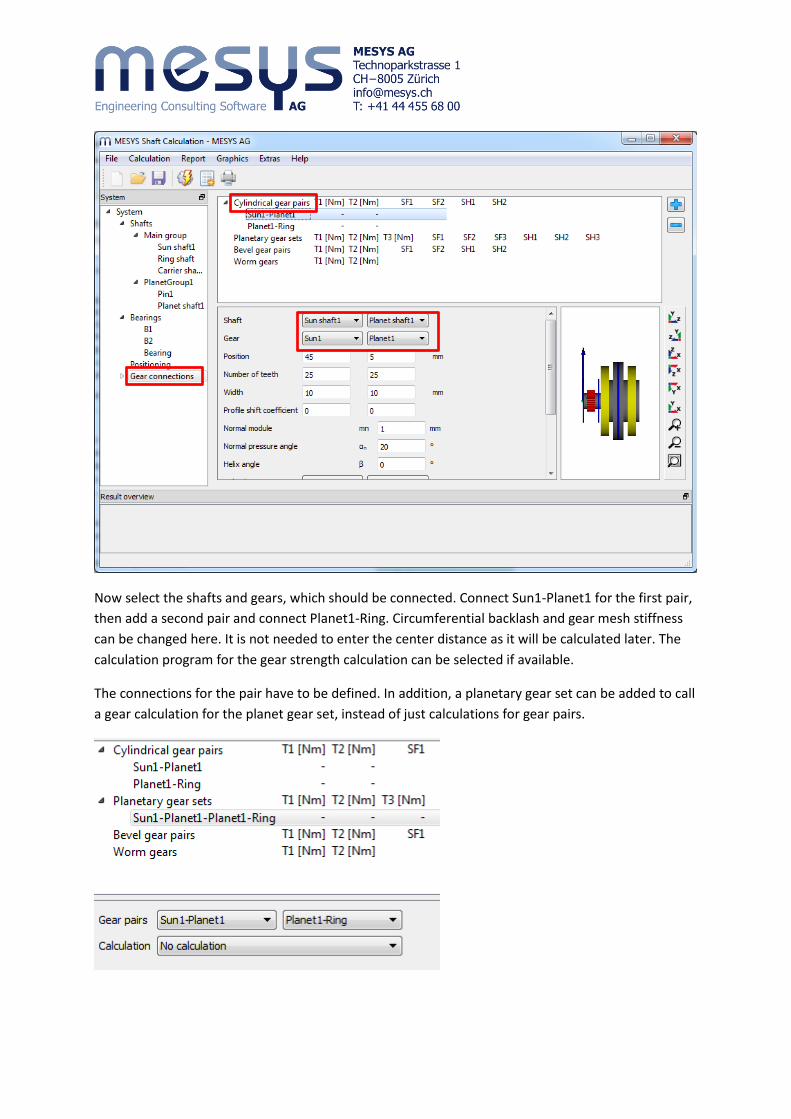
Now select the shafts and gears, which should be connected. Connect Sun1-Planet1 for the first pair,
then add a second pair and connect Planet1-Ring. Circumferential backlash and gear mesh stiffness
can be changed here. It is not needed to enter the center distance as it will be calculated later. The
calculation program for the gear strength calculation can be selected if available.
The connections for the pair have to be defined. In addition, a planetary gear set can be added to call
a gear calculation for the planet gear set, instead of just calculations for gear pairs.
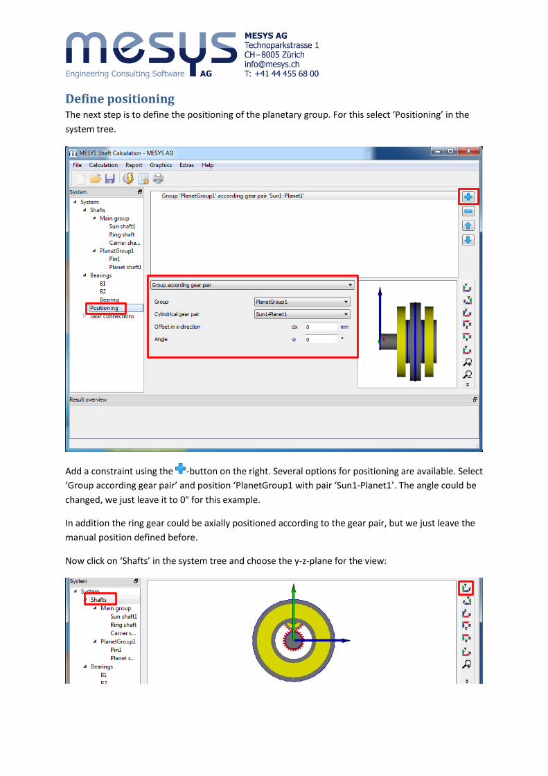
Define positioning The next step is to define the positioning of the planetary group. For this select ‘Positioning’ in the
system tree.
Add a constraint using the -button on the right. Several options for positioning are available. Select
‘Group according gear pair’ and position ‘PlanetGroup1 with pair ‘Sun1-Planet1’. The angle could be
changed, we just leave it to 0° for this example.
In addition the ring gear could be axially positioned according to the gear pair, but we just leave the
manual position defined before.
Now click on ‘Shafts’ in the system tree and choose the y-z-plane for the view:

Running the calculation Before running the calculation we have to define the
speed for the system. Enter a speed of 2000rpm for
‘Sun1’.
For all other shafts the flag behind the input of speed
should not be set as the speed is calculated by the
program. A speed for the ring could be set, if it is not
equal zero.
After running the calculation the results overview should look similar to the following:
The safety factors for the gears depend on the
selected program for gear calculations. We also did
not enter any details for the gear calculations.
Minimum bearing life is 3200h, static bearing safety
is 3.4. Therefore bearings could be ok, dependent on
the needs for life. Minimum gear safety is 1.10 for
the flank and 1.8 for the root stresses, so gears
should also be ok.
After running the calculation also all three planets
are shown.
This can now be used to detail the shaft geometry
and optimize the gears.
Gear calculations For gear calculations the ‘Required Life’ on page ‘System’ should be defined. Also either ‘Consider
gears as stiffness’ should be set which results in an automatic increase of shaft diameter according to
the gears, or you should consider the gear stiffness in the shaft geometry yourself.
The gear calculation can be opened by selecting the gear pair in the system
tree. Dependent on the gear calculation program it is opened within the
shaft calculation program or as an extra window. Gear parameters can be
changed and are read back on closing the gear calculation. Here we have
three entries for calculations. Two gear pair calculations and one planet gear calculation.

On the page ‘Gear connections’ the torque for each gear is shown and its safety factors. Selecting
‘Cylindrical gear pairs’ an overview for gear pair data is shown in a table.
Here only safety factors are shown for the planetary gear stage as no calculation program is selected
for the pairs. Note that for the gear pairs the torque is shown for one contact, the sum of all contacts
is used for the planetary gear sets.

Graphics for gear pairs Two graphics for gear pairs are available so far. The line load and the gap width.
The line load showns the loading of all three contacts. The small difference is because of the weight
of the shafts. The gap width shows the gap between the flank if the contact would be just on one
point. So in this case a flank line correction of 0.3m could be made, but this small value can be
ignored. Gear mesh stiffness, shaft and bearing stiffness have an influence to these diagrams. But
also manufacturing errors and housing stiffness have an influence on the real gearbox.

Adding a second stage For the second stage, a copy is made for sun shaft and carrier
shaft first. Click on the shaft using the right mouse button and
select ‘Duplicate’. Then rename the shafts ‘Sun shaft2’ and
‘Carrier shaft2’ and move them to positions 60 and 82.5.
Replace the support of ‘Sun shaft2’ with a general constraint to
couple it with carrier1 and remove the coupling ‘Input’.
Rename ‘Sun1’ to ‘Sun2’ and clear the flag for input of speed.
For ‘Carrier1’ remove the coupling for reaction moment.
For ‘Carrier2’ rename the bearings to ‘B4’ and ‘B5’.
We change the geometry of the ring shaft using a start
position of 20 and add a second ring gear to it with same
geometry:
Instead of one support we use two supports on the ring
gear to avoid deformations.
Then we add a new planetary group named
‘PlanetGroup2’. We duplicate the shafts ‘Pin1’ and
‘PlanetShaft2’ and move the copies to the new group
clicking with the right mouse button and choosing ‘Move to group’.
Then we rename the force and support elements in the new group and connect the pin2 to ‘Carrier
shaft2’ under ’Supports’. The bearing for the planet had to be connected with ‘Pin2’ for the outer
ring.
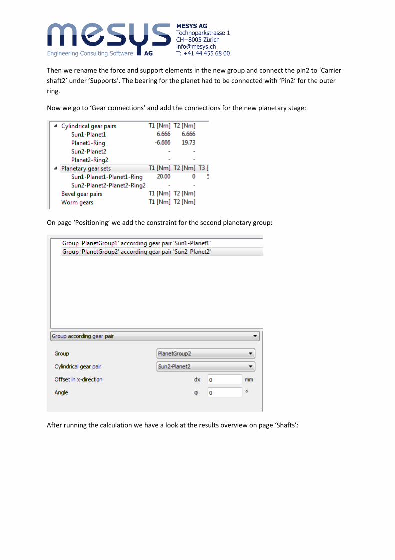
Now we go to ‘Gear connections’ and add the connections for the new planetary stage:
On page ‘Positioning’ we add the constraint for the second planetary group:
After running the calculation we have a look at the results overview on page ‘Shafts’:
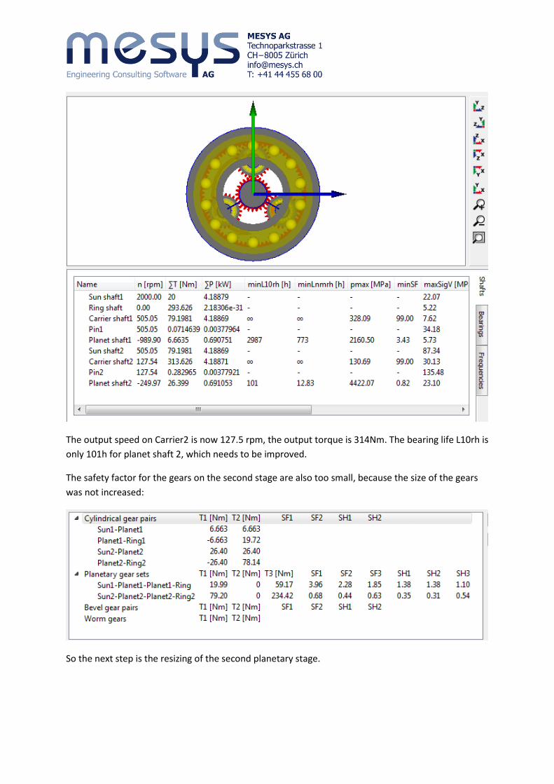
The output speed on Carrier2 is now 127.5 rpm, the output torque is 314Nm. The bearing life L10rh is
only 101h for planet shaft 2, which needs to be improved.
The safety factor for the gears on the second stage are also too small, because the size of the gears
was not increased:
So the next step is the resizing of the second planetary stage.