Turning Full Slides
36
© R. Jerz 1 2/24/2006 Chapter 23 Machining Processes Used to Produce Round Shapes: Turning and Hole Making
-
Upload
anonymous-mkdafwif -
Category
Documents
-
view
226 -
download
3
description
Turning
Transcript of Turning Full Slides
© R. Jerz 1 2/24/2006
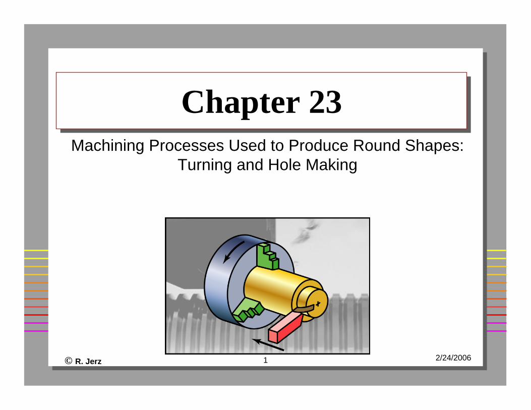
Chapter 23Chapter 23Machining Processes Used to Produce Round Shapes:
Turning and Hole Making
© R. Jerz 2 2/24/2006
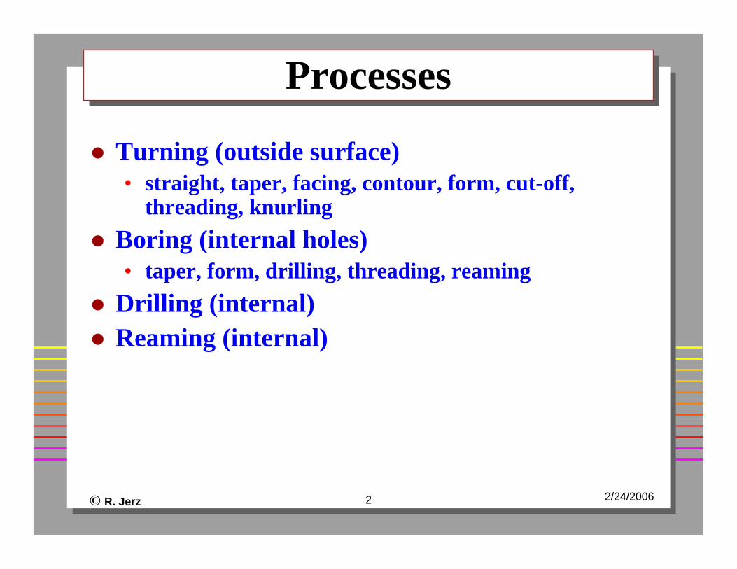
ProcessesProcesses
Turning (outside surface)• straight, taper, facing, contour, form, cut-off,
threading, knurlingBoring (internal holes)• taper, form, drilling, threading, reaming
Drilling (internal)Reaming (internal)
© R. Jerz 3 2/24/2006
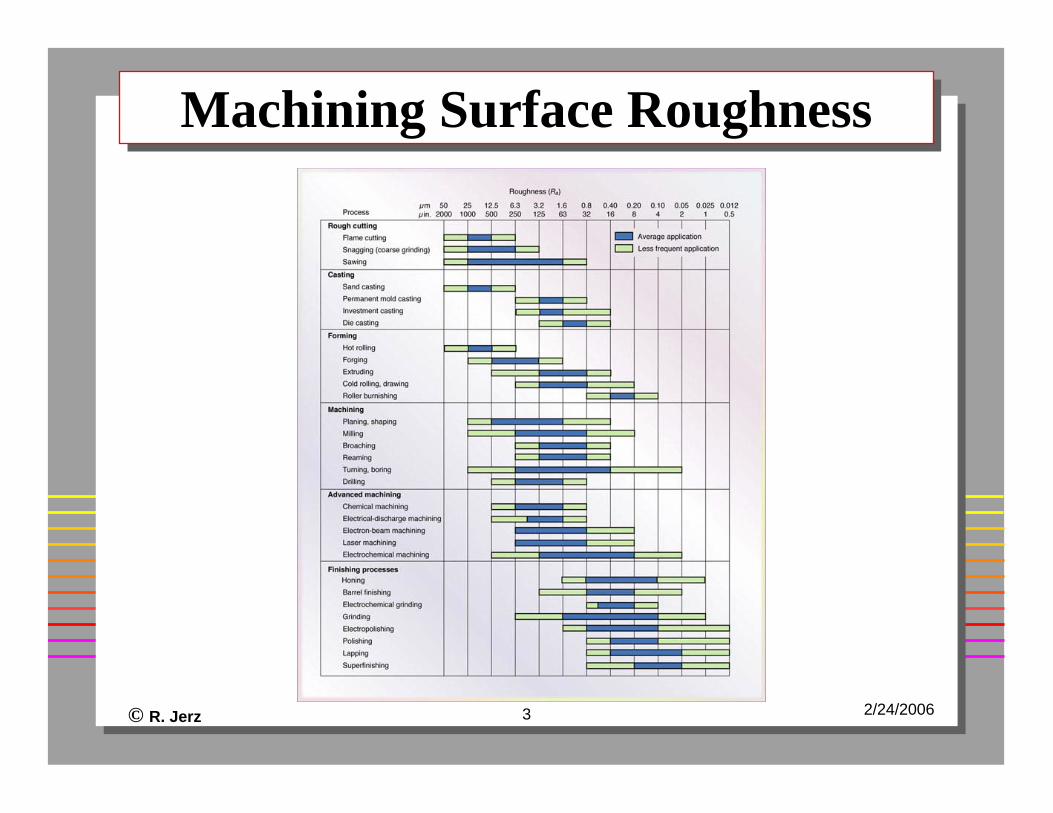
Machining Surface RoughnessMachining Surface Roughness
© R. Jerz 4 2/24/2006
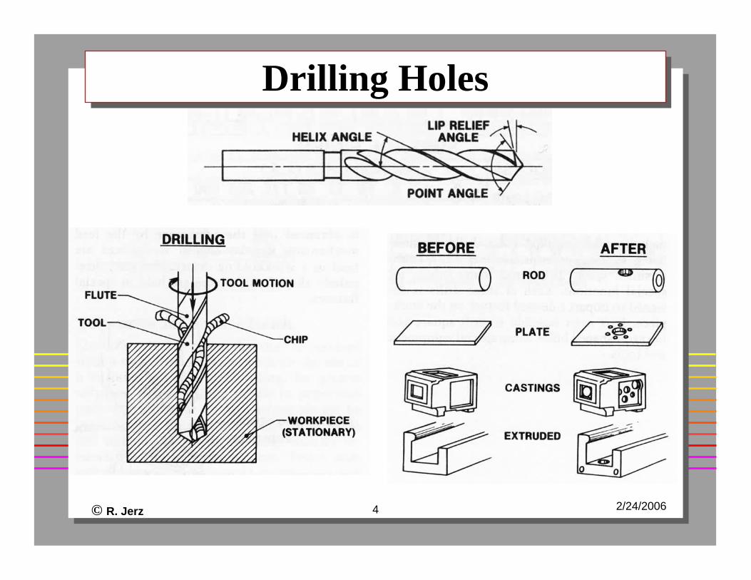
Drilling HolesDrilling Holes
© R. Jerz 5 2/24/2006
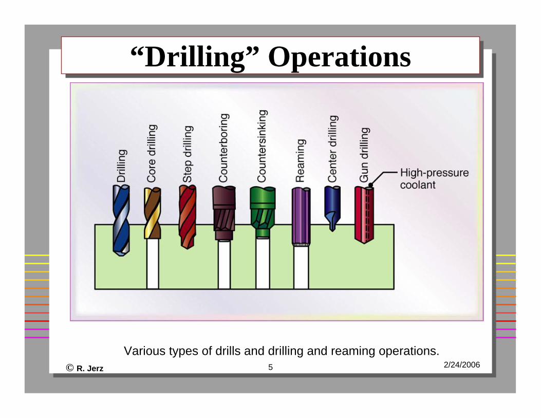
“Drilling” Operations“Drilling” Operations
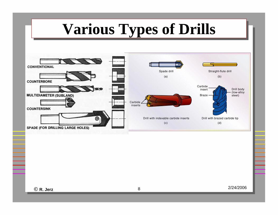
Various types of drills and drilling and reaming operations.
© R. Jerz 6 2/24/2006
Drilling VideoDrilling Video
© R. Jerz 7 2/24/2006
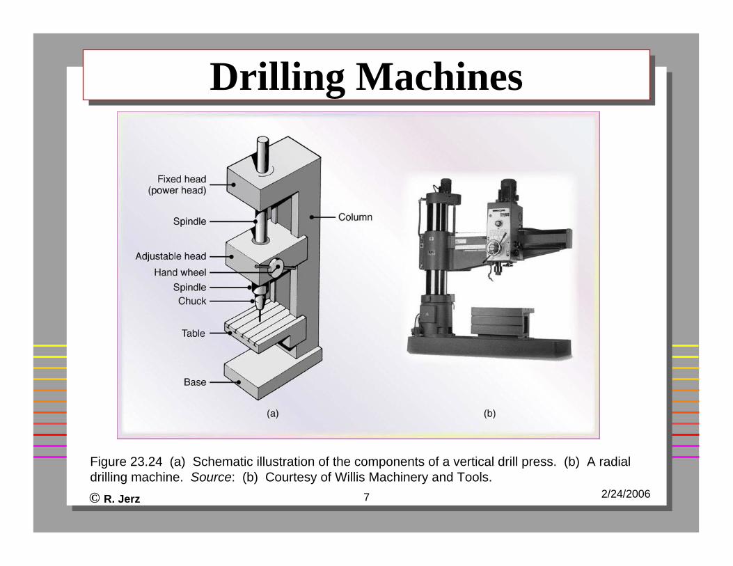
Drilling MachinesDrilling Machines
Figure 23.24 (a) Schematic illustration of the components of a vertical drill press. (b) A radial drilling machine. Source: (b) Courtesy of Willis Machinery and Tools.
© R. Jerz 8 2/24/2006
Various Types of DrillsVarious Types of Drills
© R. Jerz 9 2/24/2006
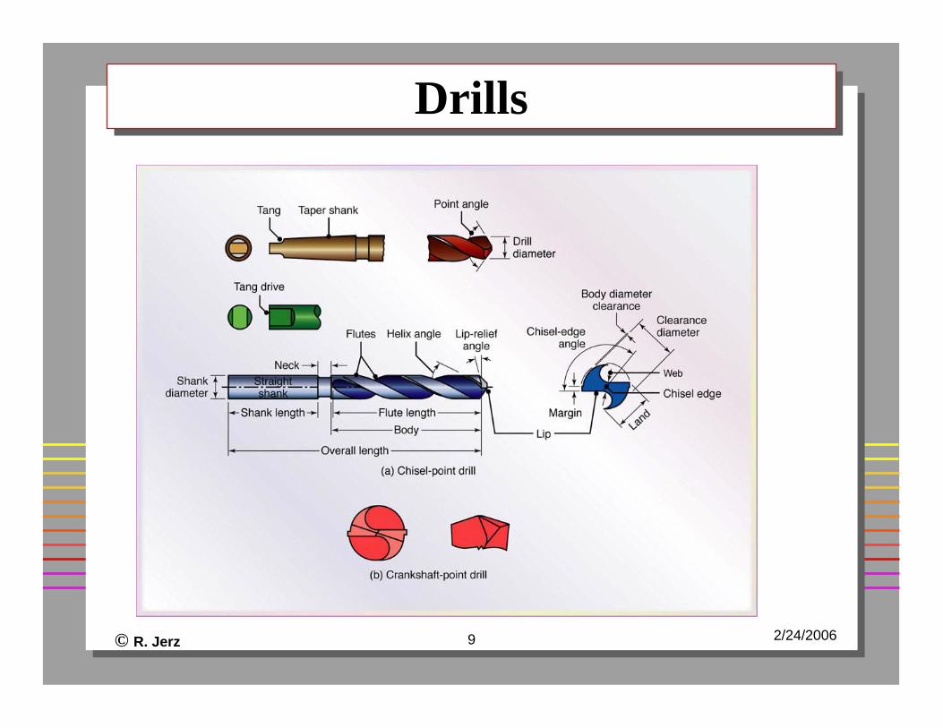
DrillsDrills
© R. Jerz 10 2/24/2006
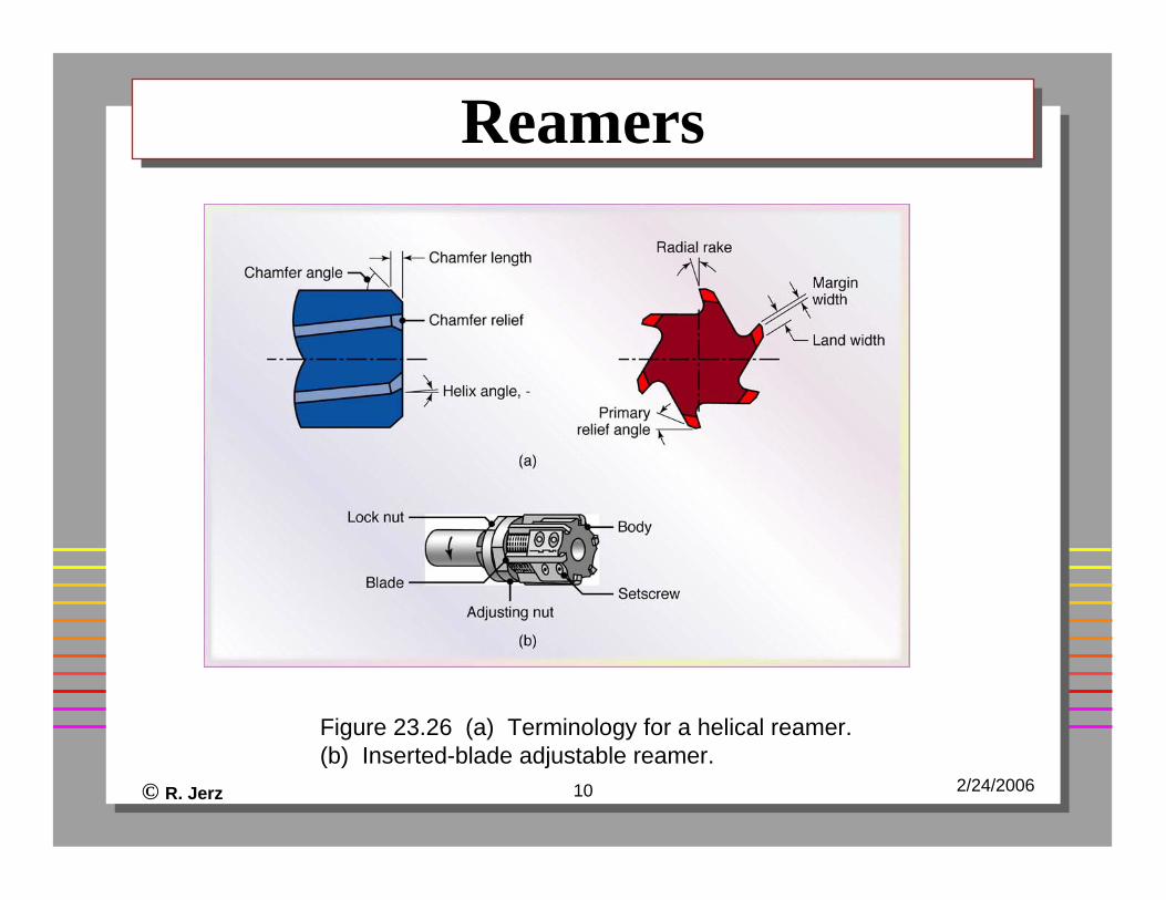
ReamersReamers
Figure 23.26 (a) Terminology for a helical reamer. (b) Inserted-blade adjustable reamer.
© R. Jerz 11 2/24/2006
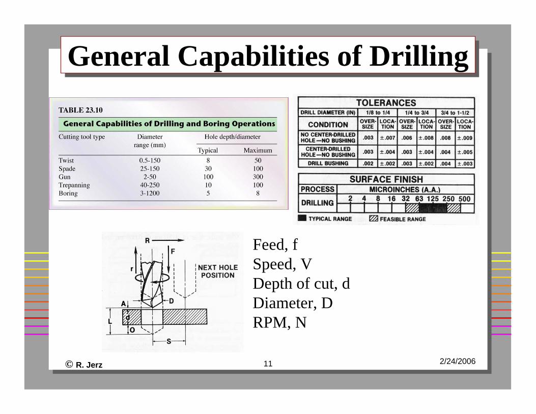
General Capabilities of DrillingGeneral Capabilities of Drilling
Feed, fSpeed, VDepth of cut, dDiameter, DRPM, N
© R. Jerz 12 2/24/2006
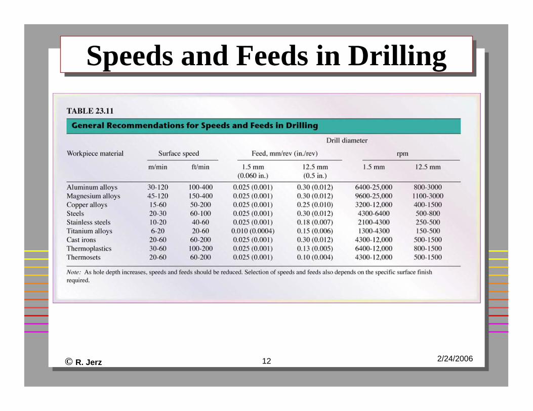
Speeds and Feeds in DrillingSpeeds and Feeds in Drilling
© R. Jerz 13 2/24/2006
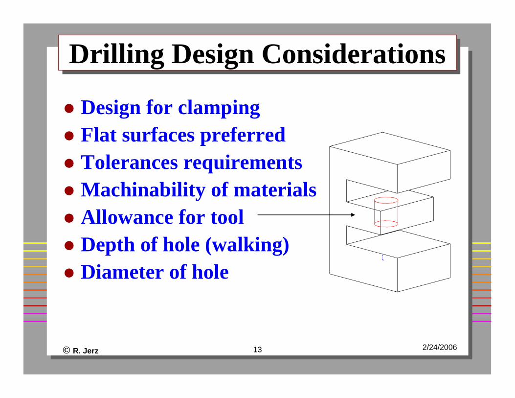
Drilling Design ConsiderationsDrilling Design Considerations
Design for clampingFlat surfaces preferredTolerances requirementsMachinability of materialsAllowance for toolDepth of hole (walking)Diameter of hole
© R. Jerz 14 2/24/2006
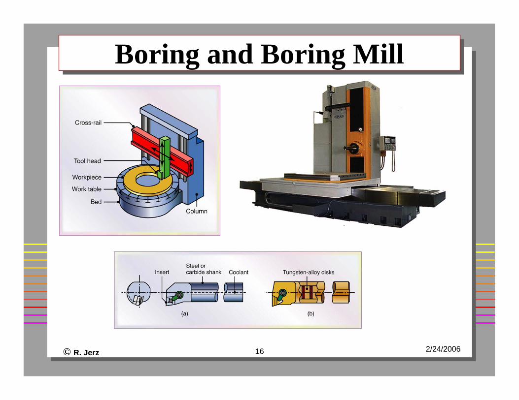
Boring Process CharacteristicsBoring Process Characteristics
Single point toolEnlarges or straightens an existing holeProduces accurate holes (better tolerances than drilling)Able to produce large internal holesCan be performed on a lathe, boring mill, or jig bore machine tools
© R. Jerz 15 2/24/2006
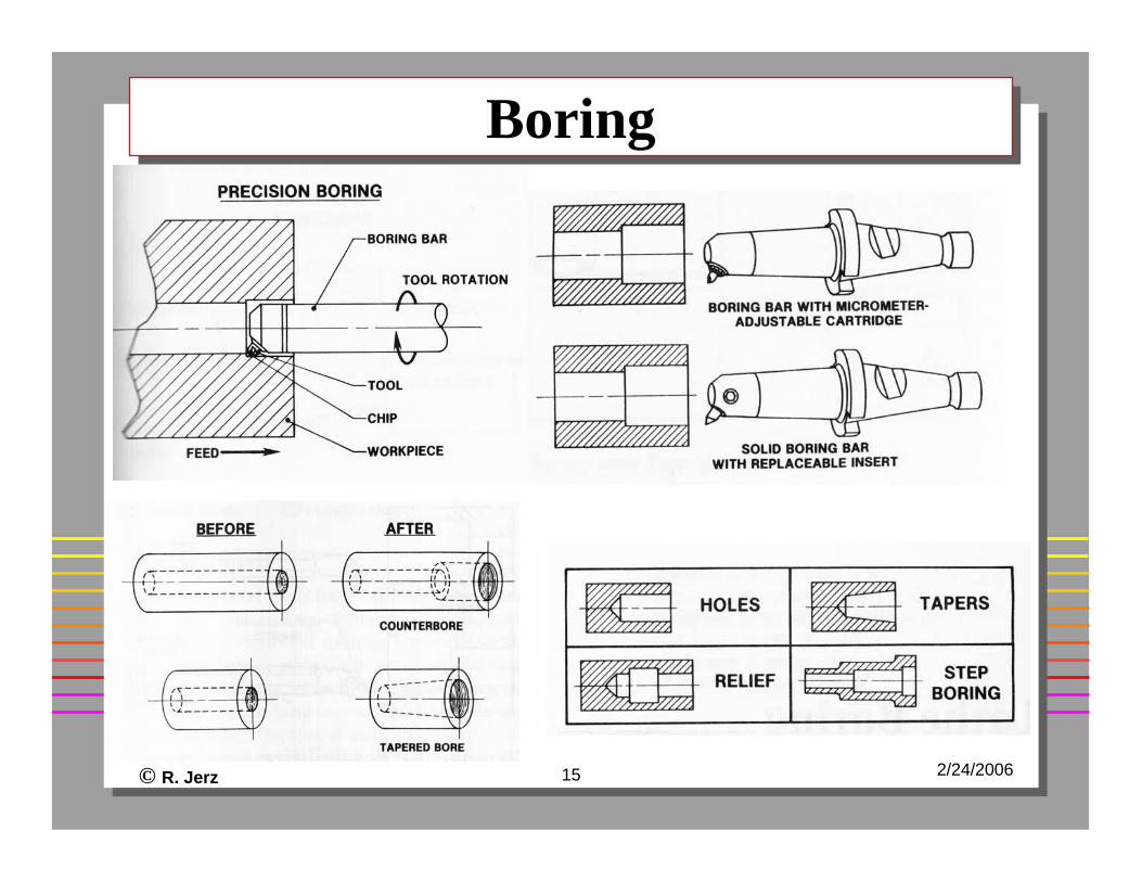
BoringBoring
© R. Jerz 16 2/24/2006
Boring and Boring MillBoring and Boring Mill
© R. Jerz 17 2/24/2006
Boring Design ConsiderationsBoring Design Considerations
Through holes, not blind holesGreater length to diameter more difficultAvoid intermittent cuts
© R. Jerz 18 2/24/2006
Turning ProcessTurning Process
Creates cylindrical external or internal shapesCreates flat surfaces on part ends (faces)Uses a single point toolWide variety of shapesThe machine tool is called a “lathe”
© R. Jerz 19 2/24/2006
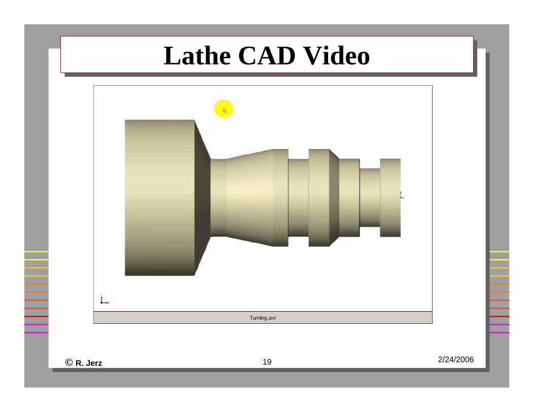
Lathe CAD VideoLathe CAD Video
© R. Jerz 20 2/24/2006
Video – Lathe/TurningVideo – Lathe/Turning
© R. Jerz 21 2/24/2006
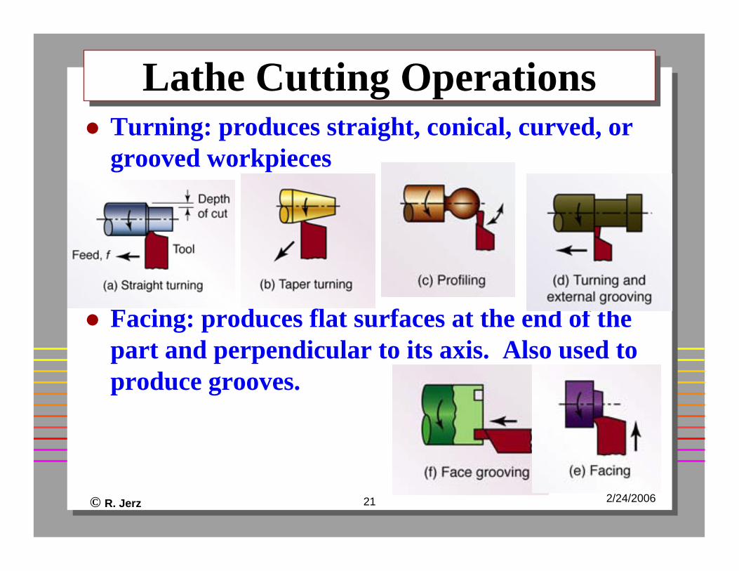
Lathe Cutting Operations Lathe Cutting Operations Turning: produces straight, conical, curved, or grooved workpieces
Facing: produces flat surfaces at the end of the part and perpendicular to its axis. Also used to produce grooves.
© R. Jerz 22 2/24/2006
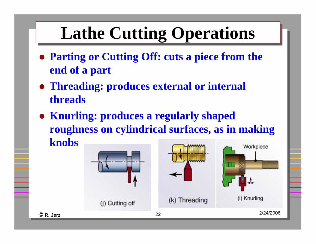
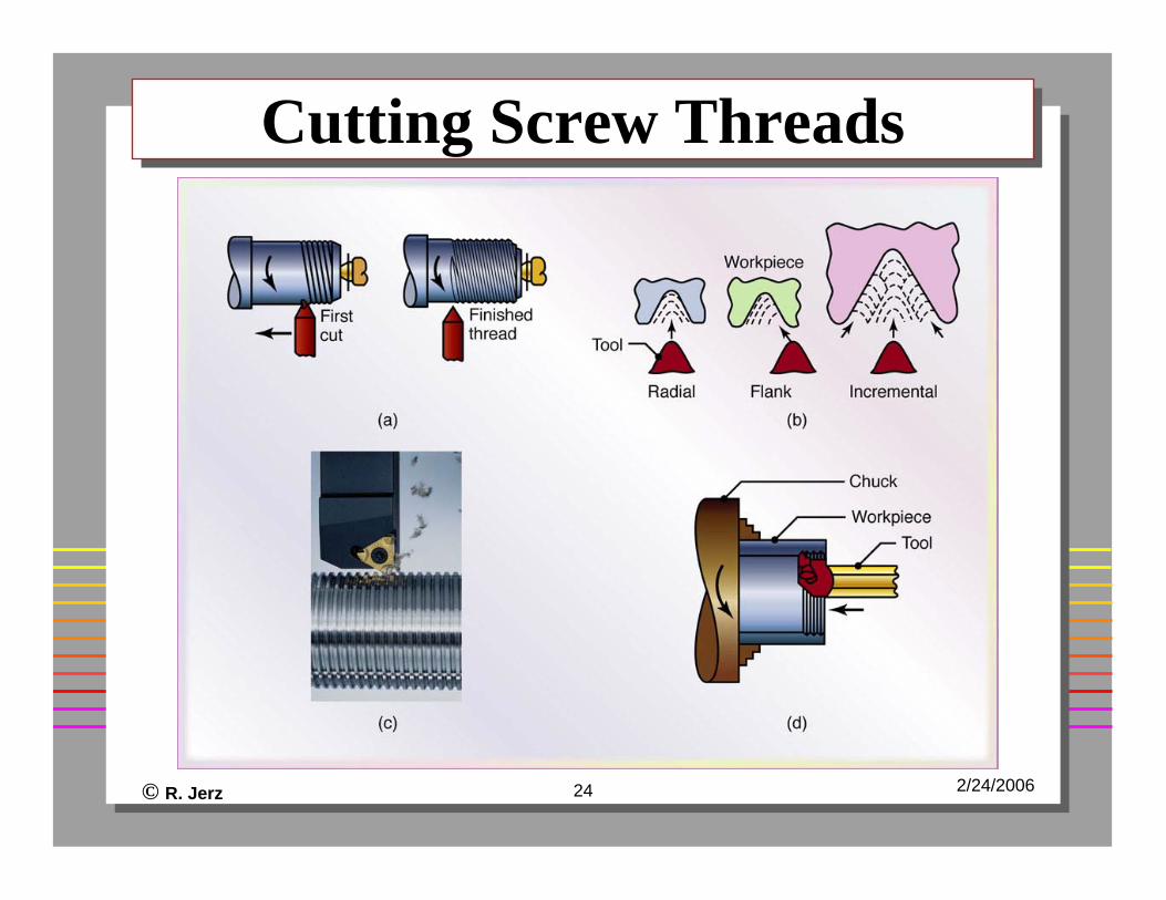
Lathe Cutting OperationsLathe Cutting OperationsParting or Cutting Off: cuts a piece from the end of a partThreading: produces external or internal threadsKnurling: produces a regularly shaped roughness on cylindrical surfaces, as in making knobs
© R. Jerz 23 2/24/2006
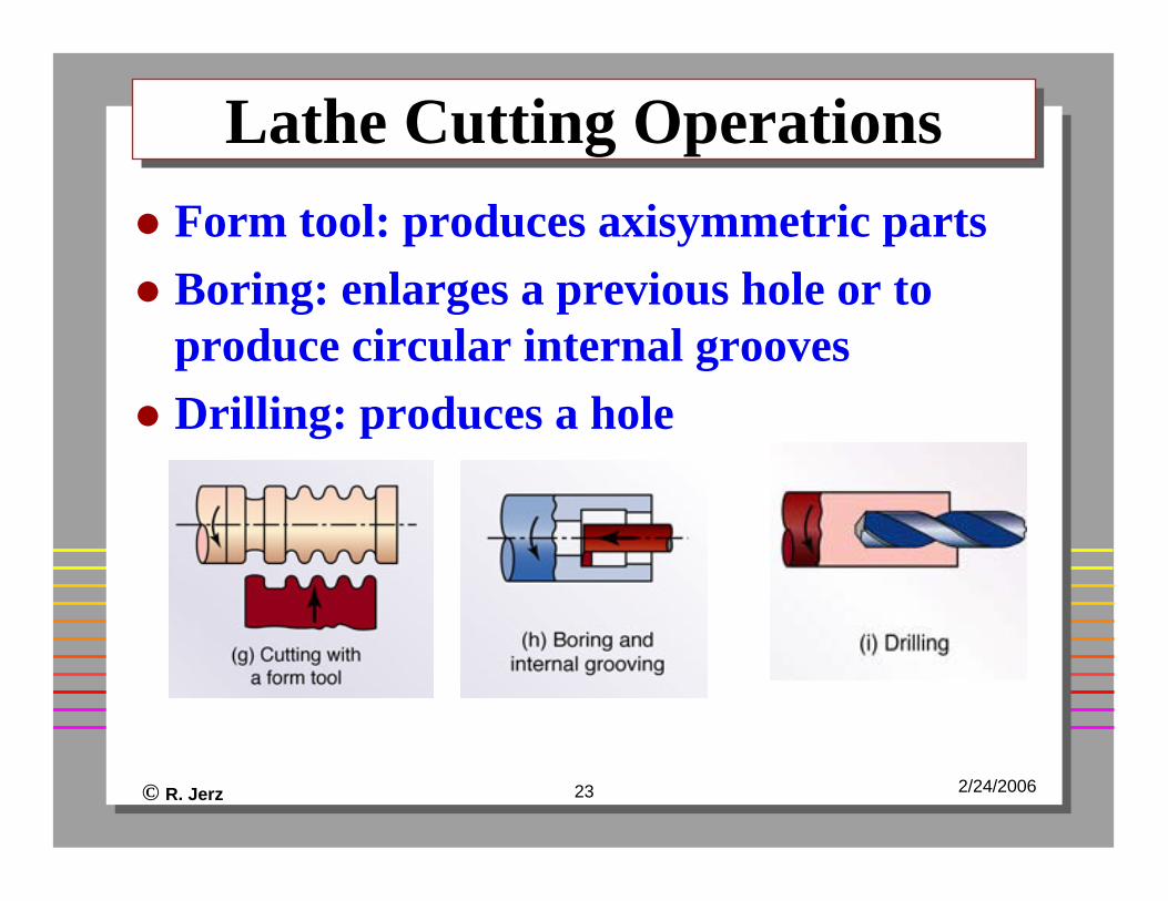
Lathe Cutting OperationsLathe Cutting OperationsForm tool: produces axisymmetric partsBoring: enlarges a previous hole or to produce circular internal groovesDrilling: produces a hole
© R. Jerz 24 2/24/2006
Cutting Screw ThreadsCutting Screw Threads
© R. Jerz 25 2/24/2006
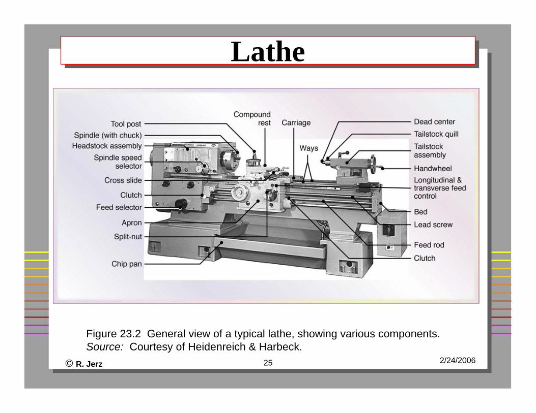
LatheLathe
Figure 23.2 General view of a typical lathe, showing various components. Source: Courtesy of Heidenreich & Harbeck.
© R. Jerz 26 2/24/2006
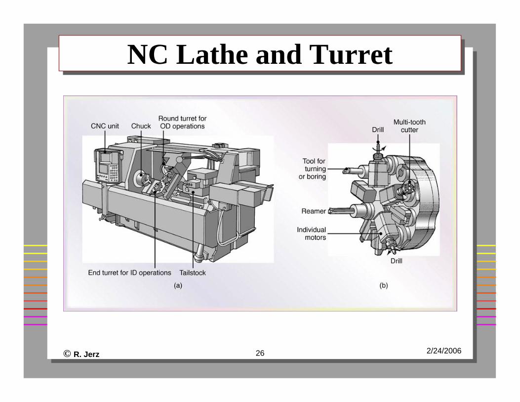
NC Lathe and TurretNC Lathe and Turret
© R. Jerz 27 2/24/2006
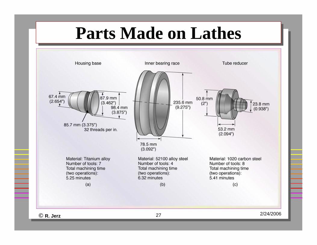
Parts Made on LathesParts Made on Lathes
© R. Jerz 28 2/24/2006
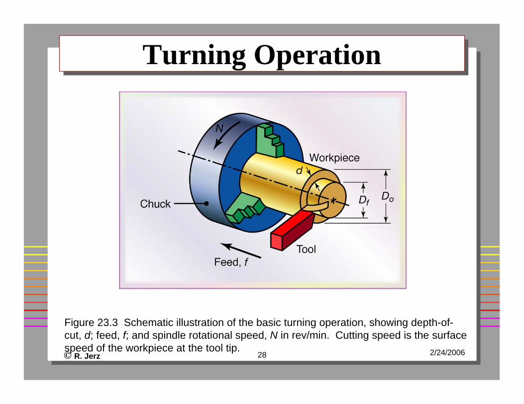
Turning OperationTurning Operation
Figure 23.3 Schematic illustration of the basic turning operation, showing depth-of-cut, d; feed, f; and spindle rotational speed, N in rev/min. Cutting speed is the surface speed of the workpiece at the tool tip.
© R. Jerz 29 2/24/2006
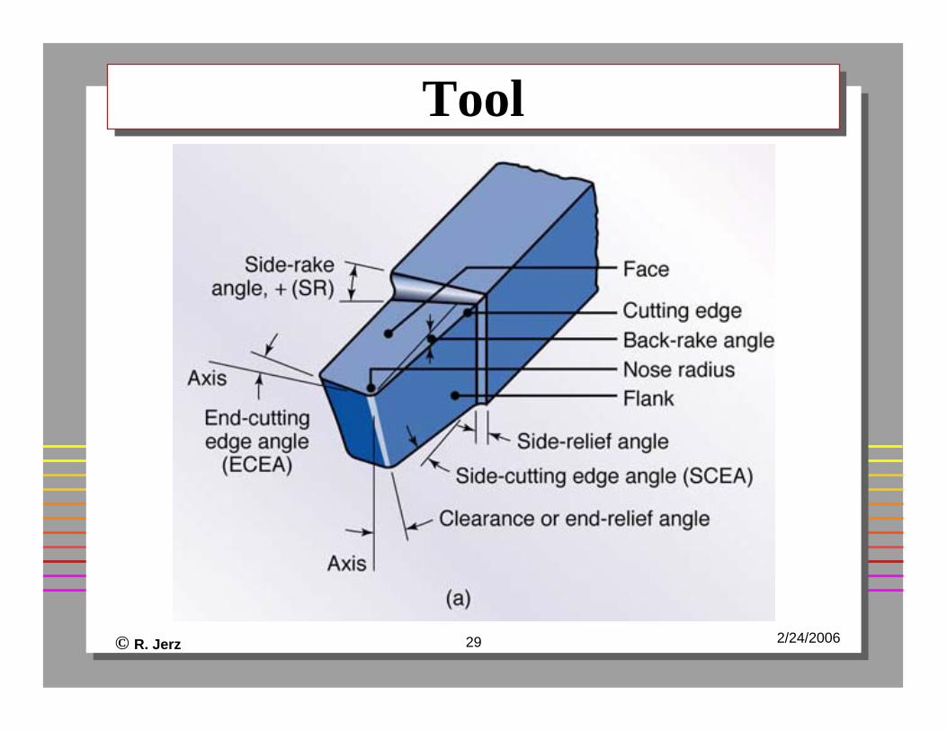
ToolTool
© R. Jerz 30 2/24/2006
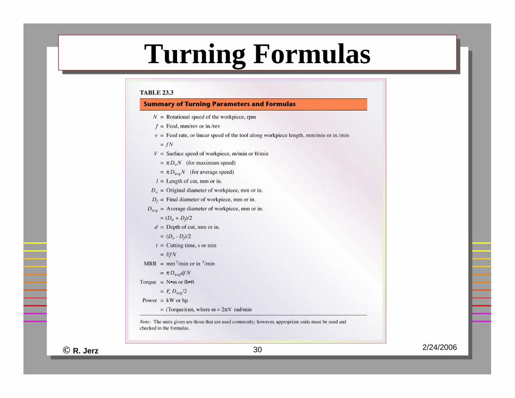
Turning FormulasTurning Formulas
© R. Jerz 31 2/24/2006
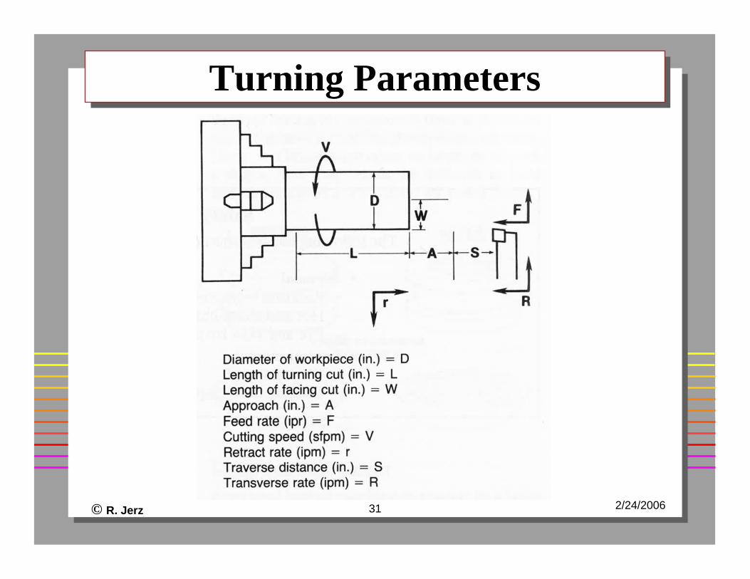
Turning ParametersTurning Parameters
© R. Jerz 32 2/24/2006
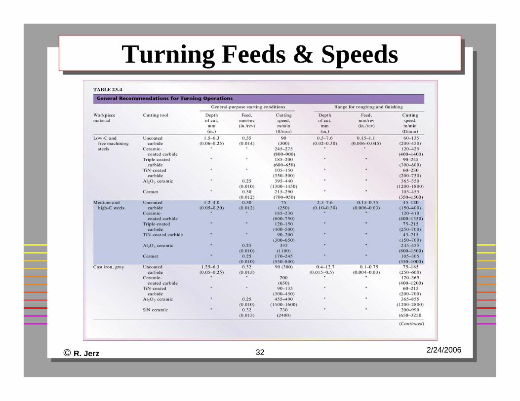
Turning Feeds & SpeedsTurning Feeds & Speeds
© R. Jerz 33 2/24/2006
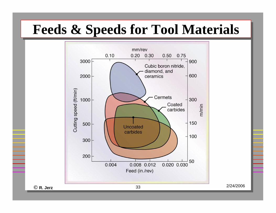
Feeds & Speeds for Tool MaterialsFeeds & Speeds for Tool Materials
© R. Jerz 34 2/24/2006
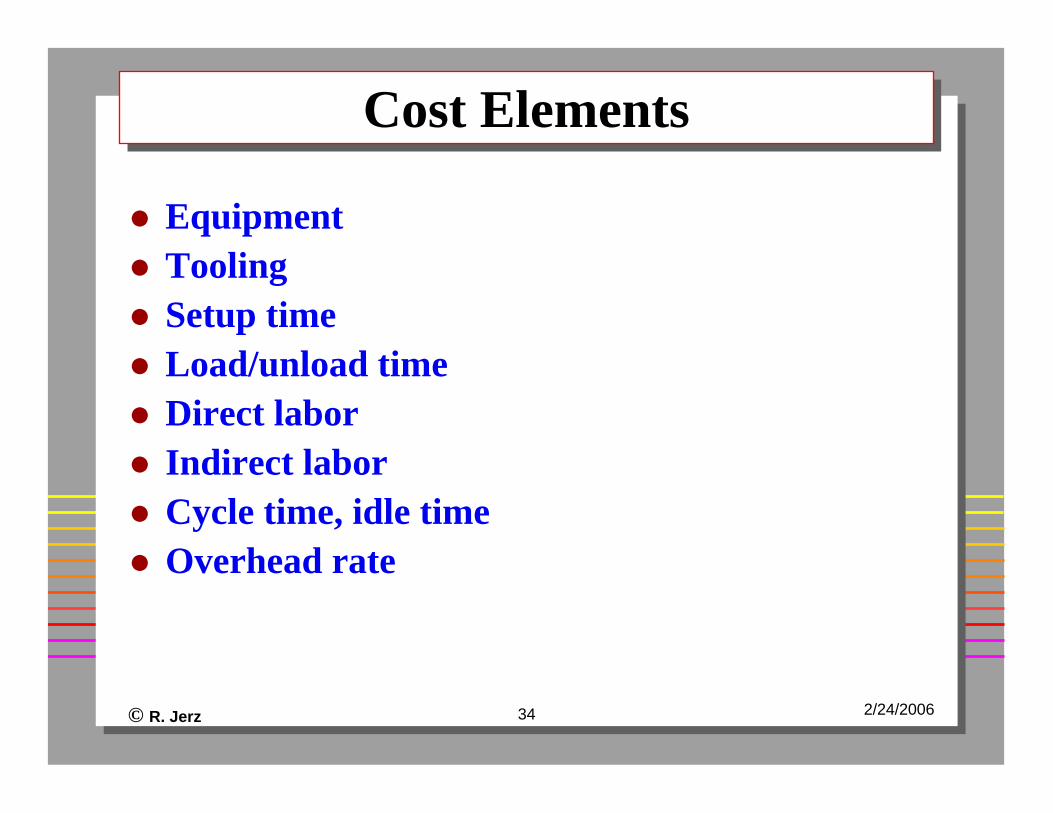
Cost ElementsCost Elements
EquipmentToolingSetup timeLoad/unload timeDirect laborIndirect laborCycle time, idle timeOverhead rate
© R. Jerz 35 2/24/2006
Safety FactorsSafety Factors
Rotating parts or toolsHot, sharp chipsEye and skin irritation from cutting fluids
© R. Jerz 36 2/24/2006
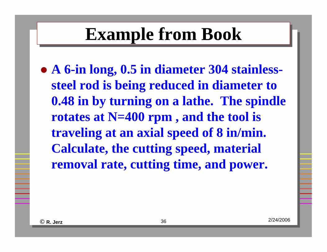
Example from BookExample from Book
A 6-in long, 0.5 in diameter 304 stainless-steel rod is being reduced in diameter to 0.48 in by turning on a lathe. The spindle rotates at N=400 rpm , and the tool is traveling at an axial speed of 8 in/min. Calculate, the cutting speed, material removal rate, cutting time, and power.