Turn Up a Network - · PDF fileChapter 5 Turn Up a Network ... Step 3 Verify that the SW...
40
CHAPTER 5-1 Cisco ONS 15454 Procedure Guide, R8.0 78-17697-01 5 Turn Up a Network This chapter explains how to turn up and test Cisco ONS 15454 networks, including point-to-point networks, linear add-drop multiplexers (ADMs), path protection configurations, and bidirectional line switched rings (BLSRs). Before You Begin This section lists the chapter procedures (NTPs). Turn to a procedure for applicable tasks (DLPs). 1. NTP-A35 Verify Node Turn-Up, page 5-2—Complete this procedure before beginning network turn-up. 2. NTP-A124 Provision a Point-to-Point Network, page 5-3—Complete as needed. 3. NTP-A173 Point-to-Point Network Acceptance Test, page 5-4—Complete this procedure after you provision a point-to-point network. 4. NTP-A38 Provision a Linear ADM Network, page 5-6—Complete as needed. 5. NTP-A174 Linear ADM Network Acceptance Test, page 5-8—Complete this procedure after you provision a linear ADM. 6. NTP-A40 Provision BLSR Nodes, page 5-10—Complete this procedure to provision ONS 15454 nodes in a two-fiber or four-fiber BLSR. 7. NTP-A126 Create a BLSR, page 5-12—Complete this procedure after you provision the BLSR nodes. 8. NTP-A175 Two-Fiber BLSR Acceptance Test, page 5-12—Complete this procedure after you create a two-fiber BLSR. 9. NTP-A176 Four-Fiber BLSR Acceptance Test, page 5-14—Complete this procedure after you create a four-fiber BLSR. 10. NTP-A178 Provision a Traditional BLSR Dual-Ring Interconnect, page 5-17—As needed, complete this procedure after you provision a BLSR. 11. NTP-A179 Provision an Integrated BLSR Dual-Ring Interconnect, page 5-19—As needed, complete this procedure after you provision a BLSR. 12. NTP-A44 Provision Path Protection Nodes, page 5-20—Complete as needed. 13. NTP-A177 Path Protection Acceptance Test, page 5-22—Complete this procedure after you create a path protection. 14. NTP-A216 Provision a Traditional Path Protection Dual-Ring Interconnect, page 5-24—As needed, complete this procedure after you provision a path protection.
Transcript of Turn Up a Network - · PDF fileChapter 5 Turn Up a Network ... Step 3 Verify that the SW...

78-17697-01
C H A P T E R5
Turn Up a NetworkThis chapter explains how to turn up and test Cisco ONS 15454 networks, including point-to-point networks, linear add-drop multiplexers (ADMs), path protection configurations, and bidirectional line switched rings (BLSRs).
Before You BeginThis section lists the chapter procedures (NTPs). Turn to a procedure for applicable tasks (DLPs).
1. NTP-A35 Verify Node Turn-Up, page 5-2—Complete this procedure before beginning network turn-up.
2. NTP-A124 Provision a Point-to-Point Network, page 5-3—Complete as needed.
3. NTP-A173 Point-to-Point Network Acceptance Test, page 5-4—Complete this procedure after you provision a point-to-point network.
4. NTP-A38 Provision a Linear ADM Network, page 5-6—Complete as needed.
5. NTP-A174 Linear ADM Network Acceptance Test, page 5-8—Complete this procedure after you provision a linear ADM.
6. NTP-A40 Provision BLSR Nodes, page 5-10—Complete this procedure to provision ONS 15454 nodes in a two-fiber or four-fiber BLSR.
7. NTP-A126 Create a BLSR, page 5-12—Complete this procedure after you provision the BLSR nodes.
8. NTP-A175 Two-Fiber BLSR Acceptance Test, page 5-12—Complete this procedure after you create a two-fiber BLSR.
9. NTP-A176 Four-Fiber BLSR Acceptance Test, page 5-14—Complete this procedure after you create a four-fiber BLSR.
10. NTP-A178 Provision a Traditional BLSR Dual-Ring Interconnect, page 5-17—As needed, complete this procedure after you provision a BLSR.
11. NTP-A179 Provision an Integrated BLSR Dual-Ring Interconnect, page 5-19—As needed, complete this procedure after you provision a BLSR.
12. NTP-A44 Provision Path Protection Nodes, page 5-20—Complete as needed.
13. NTP-A177 Path Protection Acceptance Test, page 5-22—Complete this procedure after you create a path protection.
14. NTP-A216 Provision a Traditional Path Protection Dual-Ring Interconnect, page 5-24—As needed, complete this procedure after you provision a path protection.
5-1Cisco ONS 15454 Procedure Guide, R8.0

Chapter 5 Turn Up a NetworkNTP- A35 Verify Node Turn-Up
15. NTP-A217 Provision an Integrated Path Protection Dual-Ring Interconnect, page 5-26—As needed, complete this procedure after you provision a path protection.
16. NTP-A180 Provision a Traditional BLSR/Path Protection Dual-Ring Interconnect, page 5-27—As needed, complete this procedure after you provision a path protection and BLSR.
17. NTP-A209 Provision an Integrated BLSR/Path Protection Dual-Ring Interconnect, page 5-30—As needed, complete this procedure after you provision a path protection and BLSR.
18. NTP-A224 Provision an Open-Ended Path Protection, page 5-31—As needed, complete this procedure after you provision a path protection.
19. NTP-A225 Open-Ended Path Protection Acceptance Test, page 5-33—As needed, complete this procedure after you provision an open-ended path protection.
20. NTP-A46 Subtend a Path Protection from a BLSR, page 5-36—Complete as needed.
21. NTP-A47 Subtend a BLSR from Path Protection, page 5-36—Complete as needed.
22. NTP-A48 Subtend a BLSR from a BLSR, page 5-37—Complete as needed.
23. NTP-A172 Create a Logical Network Map, page 5-39—Complete as needed.
NTP-A35 Verify Node Turn-Up
Step 1 Complete the “DLP-A60 Log into CTC” task on page 17-60 on the network you will test. If you are already logged in, continue with Step 2.
Step 2 Click the Alarms tab.
a. Verify that the alarm filter is not on. See the “DLP-A227 Disable Alarm Filtering” task on page 19-18 as necessary.
b. Verify that no unexplained alarms appear on the network. If alarms appear, investigate and resolve them before continuing. Refer to the Cisco ONS 15454 Troubleshooting Guide for procedures.
Step 3 Verify that the SW Version and Defaults shown in the node view status area match the software version and NE defaults shown in your site plan. If either is not correct, complete the following procedures as needed:
• If the software is not the correct version, install the correct version from the Cisco ONS 15454 software CD. Upgrade procedures are located in a release-specific software upgrade document. TCC2/TCC2P cards can also be ordered with the latest software release.
• If the node defaults are not correct, import the network element defaults. Refer to the “Network Element Defaults” appendix in the Cisco ONS 15454 Reference Manual.
Purpose This procedure verifies that an ONS 15454 is ready for network turn-up before adding it to a network.
Tools/Equipment None
Prerequisite Procedures Chapter 4, “Turn Up a Node”
Required/As Needed Required
Onsite/Remote Onsite
Security Level Provisioning or higher
5-2Cisco ONS 15454 Procedure Guide, R8.0
78-17697-01

Chapter 5 Turn Up a NetworkNTP- A124 Provision a Point-to-Point Network
Step 4 Click the Provisioning > General tabs. Verify that all general node information settings match the settings of your site plan. If not, see the “NTP-A81 Change Node Management Information” procedure on page 11-2.
Step 5 Click the Provisioning > Timing tabs. Verify that timing settings match the settings of your site plan. If not, see the “NTP-A85 Change Node Timing” procedure on page 11-6.
Step 6 Click the Provisioning > Network tabs. Ensure that the IP settings and other CTC network access information is correct. If not, see the “NTP-A201 Change CTC Network Access” procedure on page 11-2.
Step 7 Click the Provisioning > Protection tabs. Verify that all protection groups have been created according to your site plan. If not, see the “NTP-A203 Modify or Delete Card Protection Settings” procedure on page 11-5.
Step 8 Click the Provisioning > Security tabs. Verify that all users have been created and their security levels and policies match the settings indicated by your site plan. If not, see the “NTP-A205 Modify Users and Change Security” procedure on page 11-7.
Step 9 If Simple Network Management Protocol (SNMP) is provisioned on the node, click the Provisioning > SNMP tabs. Verify that all SNMP settings match the settings of your site plan. If not, see the “NTP-A87 Change SNMP Settings” procedure on page 11-7.
Step 10 Provision the network using the applicable procedure shown in the “Before You Begin” section on page 5-1.
Stop. You have completed this procedure.
NTP-A124 Provision a Point-to-Point Network
Step 1 Complete the “DLP-A60 Log into CTC” task on page 17-60 on an ONS 15454 in the network where you want to provision a point-to-point configuration. If you are already logged in, continue with Step 2.
Step 2 Click the Provisioning > Protection tabs. Verify that 1+1 protection is created for the OC-N cards. Complete the “DLP-A73 Create a 1+1 Protection Group” task on page 17-76 if protection has not been created.
Step 3 Repeat Steps 1 and 2 for the second point-to-point node.
Step 4 Verify that the working and protect cards in the 1+1 protection groups correspond to the physical fiber connections between the nodes, that is, verify that the working card in one node connects to the working card in the other node, and that the protect card in one node connects to the protect card in the other node.
Purpose This procedure provisions two ONS 15454s in a 1+1 point-to-point (terminal) network.
Tools/Equipment None
Prerequisite Procedures NTP-A35 Verify Node Turn-Up, page 5-2
Required/As Needed As needed
Onsite/Remote Onsite
Security Level Provisioning or higher
5-3Cisco ONS 15454 Procedure Guide, R8.0
78-17697-01

Chapter 5 Turn Up a NetworkNTP- A173 Point-to-Point Network Acceptance Test
Step 5 Complete the “DLP-A377 Provision Section DCC Terminations” task on page 20-68 for the working OC-N port on both point-to-point nodes. Alternatively, if additional bandwidth is needed for CTC management, complete the “DLP-A378 Provision Line DCC Terminations” task on page 20-70.
Note DCC terminations are not provisioned on the protect ports.
Note If the point-to-point nodes are not connected to a LAN, you will need to create the DCC terminations using a direct (craft) connection to the node. Remote provisioning is possible only after all nodes in the network have DCC terminations provisioned to in-service OC-N ports.
Step 6 Complete the “DLP-A214 Change the Service State for a Port” task on page 19-9 to put the protect card in-service.
Step 7 As needed, complete the “DLP-A380 Provision a Proxy Tunnel” task on page 20-76.
Step 8 As needed, complete the “DLP-A381 Provision a Firewall Tunnel” task on page 20-77.
Step 9 As needed, complete the “DLP-A367 Create a Provisionable Patchcord” task on page 20-50.
Step 10 Verify that timing is set up at both point-to-point nodes. If not, complete the “NTP-A28 Set Up Timing” procedure on page 4-11 for one or both of the nodes. If a node uses line timing, make its working OC-N card the timing source. The system will automatically choose the corresponding protect OC-N card as the protect timing source. This will be visible in the Maintenance > Timing tab.
Step 11 Complete the “NTP-A173 Point-to-Point Network Acceptance Test” procedure on page 5-4.
Stop. You have completed this procedure.
NTP-A173 Point-to-Point Network Acceptance Test
Caution This procedure might be service affecting if performed on a node carrying traffic.
Step 1 Complete the “DLP-A60 Log into CTC” task on page 17-60 at one of the point-to-point nodes. The node (default) view appears. If you are already logged in, continue with Step 2.
Step 2 From the View menu, choose Go to Network View.
Step 3 Click the Alarms tab.
a. Verify that the alarm filter is not on. See the “DLP-A227 Disable Alarm Filtering” task on page 19-18 as necessary.
Purpose This procedure tests a point-to-point network.
Tools/Equipment Test set and cables appropriate to the test circuit you will create
Prerequisite Procedures NTP-A124 Provision a Point-to-Point Network, page 5-3
Required/As Needed As needed
Onsite/Remote Onsite
Security Level Provisioning or higher
5-4Cisco ONS 15454 Procedure Guide, R8.0
78-17697-01

Chapter 5 Turn Up a NetworkNTP- A173 Point-to-Point Network Acceptance Test
b. Verify that no unexplained alarms appear on the network. If unexplained alarms appear, resolve them before continuing. Refer to the Cisco ONS 15454 Troubleshooting Guide if necessary.
c. Complete the “DLP-A532 Export CTC Data” task on page 22-32 to export alarm data.
Step 4 Click the Conditions tab.
a. Verify that no unexplained conditions appear on the network. If unexplained conditions appear, resolve them before continuing. Refer to the Cisco ONS 15454 Troubleshooting Guide if necessary.
b. Complete the “DLP-A532 Export CTC Data” task on page 22-32 to export the condition information.
Step 5 On the network map, double-click a point-to-point node to open it in node view.
Step 6 Create a test circuit from the login node to the other point-to-point node:
• For DS-1 circuits, complete the “NTP-A181 Create an Automatically Routed DS-1 Circuit” procedure on page 6-7. When you set the circuit state, choose IS and check the Apply to drop ports check box.
• For DS-3 circuits, complete the “NTP-A184 Create an Automatically Routed DS-3 or EC-1 Circuit” procedure on page 6-19. When you set the circuit state, choose IS and check the Apply to drop ports check box.
• For OC-N circuits, complete the “NTP-A343 Create an Automatically Routed Optical Circuit” procedure on page 6-40. When you set the circuit state, choose IS and check the Apply to drop ports check box.
Step 7 Configure the test set for the test circuit type you created:
• DS-1—If you are testing a DS-1 that is not multiplexed, you must have a DSX-1 panel or a direct DS-1 interface to the ONS 15454. Set the test set for DS-1. For information about configuring your test set, consult your test set user guide.
• DS-3—If you are testing a clear channel DS-3, you must have a DSX-3 panel or a direct DS-3 interface to the ONS 15454. Set the test set for clear channel DS-3. For information about configuring your test set, consult your test set user guide.
• DS3XM—If you are testing a DS-1 circuit on a DS3XM-6 or DS3XM-12 card you must have a DSX-3 panel or a direct DS-3 interface to the ONS 15454. Set the test set for a multiplexed DS-3. Next, choose the DS-1 to test on the multiplexed DS-3. For information about configuring your test set, consult your test set user guide.
• OC-N—If you are testing an OC-N circuit, set the test set for the applicable circuit size. For information about configuring your test set, consult your test set user guide.
Step 8 Verify the integrity of all patch cables that will be used in this test by connecting one end to the test set transmit (Tx) connector the other to the test set receive (Rx) connector. If the test set does not run error-free, check the cable for damage and check the test set to make sure it is set up correctly before going to Step 9.
Step 9 Create a physical loopback at the circuit destination card. To do so, attach one end of a patch cable to the destination port’s Tx connector; attach the other end to the port’s Rx connector.
Step 10 At the circuit source card:
a. Connect the Tx connector of the test set to the Rx connector on the circuit source card.
b. Connect the test set Rx connector to the circuit Tx connector on the circuit source card.
Step 11 Verify that the test set has a clean signal. If a clean signal is not present, repeat Steps 6 through 10 to make sure the test set and cabling are configured correctly.
5-5Cisco ONS 15454 Procedure Guide, R8.0
78-17697-01

Chapter 5 Turn Up a NetworkNTP- A38 Provision a Linear ADM Network
Step 12 If a node fails any test, repeat the test while verifying correct setup and configuration. If the test fails again, refer to the next level of support.
Step 13 Inject BIT errors from the test set. Verify that the errors appear at the test set, indicating a complete end-to-end circuit.
Step 14 Complete the “DLP-A356 TCC2/TCC2P Card Active/Standby Switch Test” task on page 20-39.
Step 15 Complete the “DLP-A255 Cross-Connect Card Side Switch Test” task on page 19-37.
Step 16 Complete the “DLP-A88 Optical 1+1 Protection Test” task on page 17-80.
Step 17 Set up and complete a bit error rate (BER) test. Use the existing configuration and follow your site requirements for the specified length of time. Record the test results and configuration.
Step 18 Remove any loopbacks, switches, or test sets from the nodes after all testing is complete.
Step 19 From the View menu, choose Go to Network View.
Step 20 Click the Alarms tab.
a. Verify that the alarm filter is not on. See the “DLP-A227 Disable Alarm Filtering” task on page 19-18 as necessary.
b. Verify that no unexplained alarms appear on the network. If unexplained alarms appear, resolve them before continuing. Refer to the Cisco ONS 15454 Troubleshooting Guide if necessary.
c. Complete the “DLP-A532 Export CTC Data” task on page 22-32 to export the alarms information.
Step 21 Repeat Steps 9 through 20 for the other point-to-point node.
Step 22 If a node fails any test, repeat the test while verifying correct setup and configuration. If the test fails again, refer to the next level of support.
Step 23 Delete the test circuit. See the “DLP-A333 Delete Circuits” task on page 20-20.
After all tests are successfully completed and no alarms exist in the network, the network is ready for service application.
Stop. You have completed this procedure.
NTP-A38 Provision a Linear ADM Network
Step 1 Complete the “DLP-A60 Log into CTC” task on page 17-60 at an ONS 15454 where you want to provision in a linear ADM network. If you are already logged in, continue with Step 2.
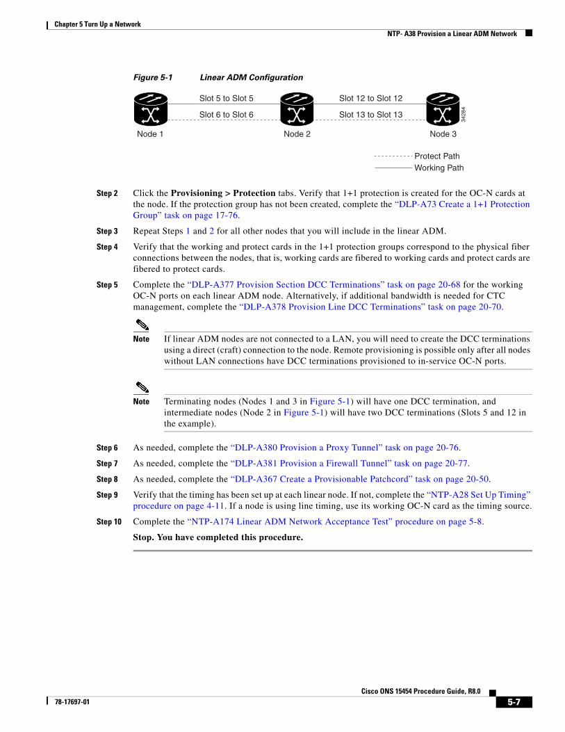
Figure 5-1 shows three ONS 15454s in a linear ADM configuration. In this example, working traffic flows from Slot 5/Node 1 to Slot 5/Node 2, and from Slot 12/Node 2 to Slot 12/Node 3. Slots 6 and 13 contain the protect OC-N cards. Slots 5 and 6 and Slots 12 and 13 are in 1+1 protection.
Purpose This procedure provisions three or more ONS 15454s in a linear add-drop multiplexer (ADM) configuration.
Tools/Equipment None
Prerequisite Procedures NTP-A35 Verify Node Turn-Up, page 5-2
Required/As Needed As needed
Onsite/Remote Onsite
Security Level Provisioning or higher
5-6Cisco ONS 15454 Procedure Guide, R8.0
78-17697-01
Chapter 5 Turn Up a NetworkNTP- A38 Provision a Linear ADM Network
Figure 5-1 Linear ADM Configuration
Step 2 Click the Provisioning > Protection tabs. Verify that 1+1 protection is created for the OC-N cards at the node. If the protection group has not been created, complete the “DLP-A73 Create a 1+1 Protection Group” task on page 17-76.
Step 3 Repeat Steps 1 and 2 for all other nodes that you will include in the linear ADM.
Step 4 Verify that the working and protect cards in the 1+1 protection groups correspond to the physical fiber connections between the nodes, that is, working cards are fibered to working cards and protect cards are fibered to protect cards.
Step 5 Complete the “DLP-A377 Provision Section DCC Terminations” task on page 20-68 for the working OC-N ports on each linear ADM node. Alternatively, if additional bandwidth is needed for CTC management, complete the “DLP-A378 Provision Line DCC Terminations” task on page 20-70.
Note If linear ADM nodes are not connected to a LAN, you will need to create the DCC terminations using a direct (craft) connection to the node. Remote provisioning is possible only after all nodes without LAN connections have DCC terminations provisioned to in-service OC-N ports.
Note Terminating nodes (Nodes 1 and 3 in Figure 5-1) will have one DCC termination, and intermediate nodes (Node 2 in Figure 5-1) will have two DCC terminations (Slots 5 and 12 in the example).
Step 6 As needed, complete the “DLP-A380 Provision a Proxy Tunnel” task on page 20-76.
Step 7 As needed, complete the “DLP-A381 Provision a Firewall Tunnel” task on page 20-77.
Step 8 As needed, complete the “DLP-A367 Create a Provisionable Patchcord” task on page 20-50.
Step 9 Verify that the timing has been set up at each linear node. If not, complete the “NTP-A28 Set Up Timing” procedure on page 4-11. If a node is using line timing, use its working OC-N card as the timing source.
Step 10 Complete the “NTP-A174 Linear ADM Network Acceptance Test” procedure on page 5-8.
Stop. You have completed this procedure.
Node 1 Node 3Node 2
Slot 5 to Slot 5
Slot 6 to Slot 6
Slot 12 to Slot 12
Slot 13 to Slot 13
Working PathProtect Path
3428
4
5-7Cisco ONS 15454 Procedure Guide, R8.0
78-17697-01

Chapter 5 Turn Up a NetworkNTP- A174 Linear ADM Network Acceptance Test
NTP-A174 Linear ADM Network Acceptance Test
Step 1 Complete the “DLP-A60 Log into CTC” task on page 17-60 on a node in the linear ADM network you are testing. If you are already logged in, continue with Step 2.
Step 2 From the View menu, choose Go to Network View.
Step 3 Click the Alarms tab.
a. Verify that the alarm filter is not on. See the “DLP-A227 Disable Alarm Filtering” task on page 19-18 as necessary.
b. Verify that no unexplained alarms appear on the network. If unexplained alarms appear, resolve them before continuing. Refer to the Cisco ONS 15454 Troubleshooting Guide if necessary.
c. Complete the “DLP-A532 Export CTC Data” task on page 22-32 to export the alarm information.
Step 4 Click the Conditions tab.
a. Verify that no unexplained conditions appear on the network. If unexplained conditions appear, resolve them before continuing. Refer to the Cisco ONS 15454 Troubleshooting Guide if necessary.
b. Complete the “DLP-A532 Export CTC Data” task on page 22-32 to export the conditions information.
Step 5 On the network map, double-click the linear ADM node you are testing to open it in node view.
Step 6 Create a test circuit from that node to an adjacent linear ADM node.
• For DS-1 circuits, complete the “NTP-A181 Create an Automatically Routed DS-1 Circuit” procedure on page 6-7. When you set the circuit state, choose IS and check the Apply to drop ports check box.
• For DS-3 circuits, complete the “NTP-A184 Create an Automatically Routed DS-3 or EC-1 Circuit” procedure on page 6-19. When you set the circuit state, choose IS and check the Apply to drop ports check box.
• For OC-N circuits, complete the “NTP-A343 Create an Automatically Routed Optical Circuit” procedure on page 6-40. When you set the circuit state, choose IS and check the Apply to drop ports check box.
Step 7 Configure the test set for the test circuit type you created:
• DS-1 card—If you are testing a DS-1 that is not multiplexed, you must have a DSX-1 panel or a direct DS-1 interface into the ONS 15454. Set the test set for DS-1. For information about configuring your test set, consult your test set user guide.
• DS-3—If you are testing a clear channel DS-3, you must have a DSX-3 panel or a direct DS-3 interface into the ONS 15454. Set the test set for clear channel DS-3. For information about configuring your test set, consult your test set user guide.
Purpose This procedure tests a linear ADM network.
Tools/Equipment Test set and cables appropriate to the test circuit you will create.
Prerequisite Procedures NTP-A38 Provision a Linear ADM Network, page 5-6
Required/As Needed As needed
Onsite/Remote Onsite
Security Level Provisioning or higher
5-8Cisco ONS 15454 Procedure Guide, R8.0
78-17697-01

Chapter 5 Turn Up a NetworkNTP- A174 Linear ADM Network Acceptance Test
• DS3XM—If you are testing a DS-1 circuit on a DS3XM-6 or DS3XM-12 card you must have a DSX-3 panel or a direct DS-3 interface to the ONS 15454. Set the test set for a multiplexed DS-3, then choose the DS-1 to test on the multiplexed DS-3. For information about configuring your test set, consult your test set user guide.
• OC-N—If you are testing an OC-N circuit, set the test set for the applicable circuit size. For information about configuring your test set, consult your test set user guide.
Step 8 Verify the integrity of all patch cables that will be used in this test by connecting one end to the test set Tx connector and the other end to the test set Rx connector. If the test set does not run error-free, check the cable for damage and check the test set to make sure it is set up correctly before going to the next step.
Step 9 Create a physical loopback at the circuit destination card. To do so, attach one end of a patch cable to the destination port’s Tx connector; attach the other end to the destination port’s Rx connector.
Step 10 At the circuit source card:
a. Connect the Tx connector of the test set to the circuit Rx connector.
b. Connect the test set Rx connector to the circuit Tx connector.
Step 11 Verify that the test set shows a clean signal. If a clean signal does not appear, repeat Steps 6 through 10 to make sure the test set and cabling are configured correctly.
Step 12 Inject BIT errors from the test set. Verify that the errors appear at the test set, indicating a complete end-to-end circuit.
Step 13 Complete the “DLP-A356 TCC2/TCC2P Card Active/Standby Switch Test” task on page 20-39.
Step 14 Complete the “DLP-A255 Cross-Connect Card Side Switch Test” task on page 19-37.
Step 15 Complete the “DLP-A88 Optical 1+1 Protection Test” task on page 17-80 to test the OC-N port protection group switching.
Step 16 Set up and complete a BER test. Use the existing configuration and follow your site requirements for length of time. Record the test results and configuration.
Step 17 Remove any loopbacks, switches, or test sets from the nodes after all testing is complete.
Step 18 In network view, click the Alarms tab.
a. Verify that the alarm filter is not on. See the “DLP-A227 Disable Alarm Filtering” task on page 19-18 as necessary.
b. Verify that no unexplained alarms appear on the network. If unexplained alarms appear, resolve them before continuing. Refer to the Cisco ONS 15454 Troubleshooting Guide if necessary.
Step 19 Delete the test circuit. See the “DLP-A333 Delete Circuits” task on page 20-20.
Step 20 Repeat Steps 6 through 19 for the next linear ADM node you are testing.
Step 21 If a node fails any test, repeat the test while verifying correct setup and configuration. If the test fails again, refer to the next level of support.
After all tests are successfully completed and no alarms exist in the network, the network is ready for service application.
Stop. You have completed this procedure.
5-9Cisco ONS 15454 Procedure Guide, R8.0
78-17697-01

Chapter 5 Turn Up a NetworkNTP- A40 Provision BLSR Nodes
NTP-A40 Provision BLSR Nodes
Step 1 Complete the “DLP-A44 Install Fiber-Optic Cables for BLSR Configurations” task on page 17-47, verifying that the following rules are observed:
• Verify that the east port at one node is connected to the west port on an adjacent node, and this east-to-west port connection is used at all BLSR nodes, similar to Figure 5-2. In the figure, the OC-N drop card on the left side of the shelf is the west port, and the drop card on the right side of the shelf is considered the east port.
Figure 5-2 Four-Node, Two-Fiber BLSR Fiber Connection Example
• For four-fiber BLSRs, verify that the same east port to west port connection is used for the working and protect fibers, similar to Figure 5-3. Verify that the working and protect card connections are not mixed. The working cards are the cards where you will provision the DCC terminations.
Purpose This procedure provisions ONS 15454 nodes for a BLSR.
Tools/Equipment None
Prerequisite Procedures NTP-A35 Verify Node Turn-Up, page 5-2
Required/As Needed As needed
Onsite/Remote Onsite
Security Level Provisioning or higher
5529
7
Node 1
West East
West East
West East
West East
Slot 5
TxRx
Slot 12
TxRx
Node 4
Slot 5
TxRx
Slot 12
TxRx
Node 2
Slot 5
TxRx
Slot 12
TxRx
Node 3
Slot 5
TxRx
Slot 12
TxRx
5-10Cisco ONS 15454 Procedure Guide, R8.0
78-17697-01

Chapter 5 Turn Up a NetworkNTP- A40 Provision BLSR Nodes
Figure 5-3 Four-Node, Four-Fiber BLSR Fiber Connection Example
Step 2 Log into an ONS 15454 that you want to configure in a BLSR. See the “DLP-A60 Log into CTC” task on page 17-60. If you are already logged in, continue with Step 3.
Step 3 Complete the “DLP-A377 Provision Section DCC Terminations” task on page 20-68. Provision the two ports/cards that will serve as the BLSR ports at the node. For four-fiber BLSRs, provision the DCC terminations on the OC-N cards that will carry the working traffic, but do not provision DCCs on the protect cards.
Note If an ONS 15454 is not connected to a corporate LAN, DCC provisioning must be performed through a direct (craft) connection to the node. Remote provisioning is possible only after all nodes in the network have DCCs provisioned to IS-NR OC-N ports.
Step 4 For four-fiber BLSRs, complete the “DLP-A214 Change the Service State for a Port” task on page 19-9 to put the protect OC-N cards/ports in service.
Step 5 Repeat Steps 2 through 4 at each node that will be in the BLSR. Verify that the EOC (DCC Termination Failure) and LOS (Loss of Signal) are cleared after DCCs are provisioned on all nodes in the ring.
Step 6 As needed, complete the “DLP-A380 Provision a Proxy Tunnel” task on page 20-76.
Step 7 As needed, complete the “DLP-A381 Provision a Firewall Tunnel” task on page 20-77.
Step 8 As needed, complete the “DLP-A367 Create a Provisionable Patchcord” task on page 20-50.
Step 9 If a BLSR span passes through third-party equipment that cannot transparently transport the K3 byte, complete the “DLP-A89 Remap the K3 Byte” task on page 17-82. This task is not necessary for most users.
Step 10 Complete the “NTP-A126 Create a BLSR” procedure on page 5-12.
6195
8
Node 1
West East
West East
West East
West East
Slot5
Slot12
Node 4
Slot5
Slot12
Node 2
Slot5
Slot12
Node 3
Slot5
Slot12
TxRx
Slot6
Slot13
TxRx
Slot6
Slot13
TxRx
Slot6
Slot13
TxRx
Slot6
Slot13
Working fibersProtect fibers
5-11Cisco ONS 15454 Procedure Guide, R8.0
78-17697-01

Chapter 5 Turn Up a NetworkNTP- A126 Create a BLSR
Stop. You have completed this procedure.
NTP-A126 Create a BLSR
Step 1 Complete the “DLP-A60 Log into CTC” task on page 17-60 at a node on the network where you will create the BLSR.
Step 2 Complete one of the following tasks:
• DLP-A328 Create a Two-Fiber BLSR Using the BLSR Wizard, page 20-16 – Use this task to create a two-fiber BLSR using the CTC BLSR wizard. The BLSR wizard checks to see that each node is ready for BLSR provisioning, then provisions all the nodes at once. Using the BLSR wizard is recommended.
• DLP-A362 Create a Four-Fiber BLSR Using the BLSR Wizard, page 20-45—Use this task to create a four-fiber BLSR using the CTC BLSR wizard. The BLSR wizard checks to see that each node is ready for BLSR provisioning, then provisions all the nodes at once. Using the BLSR wizard is recommended.
• DLP-A329 Create a Two-Fiber BLSR Manually, page 20-18— Use this task to provision a two-fiber BLSR manually at each node that will be in the BLSR.
• DLP-A363 Create a Four-Fiber BLSR Manually, page 20-46—Use this task to provision a four-fiber BLSR manually at each node that will be in the BLSR.
Step 3 Complete the “NTP-A175 Two-Fiber BLSR Acceptance Test” procedure on page 5-12 or the “NTP-A176 Four-Fiber BLSR Acceptance Test” procedure on page 5-14.
Stop. You have completed this procedure.
NTP-A175 Two-Fiber BLSR Acceptance Test
Purpose This procedure creates a BLSR at each BLSR-provisioned node.
Tools/Equipment None
Prerequisite Procedures NTP-A40 Provision BLSR Nodes, page 5-10
Required/As Needed As needed; required to complete BLSR provisioning
Onsite/Remote Onsite or remote
Security Level Provisioning or higher
Purpose This procedure tests a two-fiber BLSR.
Tools/Equipment Test set and cables appropriate for the test circuit
Prerequisite Procedures NTP-A40 Provision BLSR Nodes, page 5-10
NTP-A126 Create a BLSR, page 5-12
Required/As Needed As needed
5-12Cisco ONS 15454 Procedure Guide, R8.0
78-17697-01

Chapter 5 Turn Up a NetworkNTP- A175 Two-Fiber BLSR Acceptance Test
Note This procedure requires that you create test circuits and perform ring switches around the ring. For clarity, “Node 1” refers to the login node where you begin the procedure. “Node 2” refers to the node connected to the east OC-N trunk (span) card of Node 1.
Step 1 Complete the “DLP-A60 Log into CTC” task on page 17-60 at one of the ONS 15454s on the BLSR you are testing. (This node will be called Node 1.) If you are already logged in, continue with Step 2.
Step 2 From the View menu, choose Go to Network View.
Step 3 Click the Alarms tab.
a. Verify that the alarm filter is not on. See the “DLP-A227 Disable Alarm Filtering” task on page 19-18 as necessary.
b. Verify that no unexplained alarms appear on the network. If unexplained alarms appear, resolve them before continuing. Refer to the Cisco ONS 15454 Troubleshooting Guide if necessary.
c. Complete the “DLP-A532 Export CTC Data” task on page 22-32 to export the alarm information.
Step 4 Click the Conditions tab.
a. Verify that no unexplained conditions appear on the network. If unexplained conditions appear, resolve them before continuing. Refer to the Cisco ONS 15454 Troubleshooting Guide if necessary.
b. Complete the “DLP-A532 Export CTC Data” task on page 22-32 to export the conditions information.
Step 5 On the network view, double-click Node 1.
Step 6 Complete the “DLP-A217 BLSR Exercise Ring Test” task on page 19-10.
Step 7 Create a test circuit from Node 1 to the node connected to the east OC-N trunk (span) card of Node 1. (This node will be called Node 2.)
• For DS-1 circuits, complete the “NTP-A181 Create an Automatically Routed DS-1 Circuit” procedure on page 6-7. When you set the circuit state, choose IS and check the Apply to drop ports check box.
• For DS-3 circuits, complete the “NTP-A184 Create an Automatically Routed DS-3 or EC-1 Circuit” procedure on page 6-19. When you set the circuit state, choose IS and check the Apply to drop ports check box.
• For OC-N circuits, complete the “NTP-A343 Create an Automatically Routed Optical Circuit” procedure on page 6-40. When you set the circuit state, choose IS and check the Apply to drop ports check box.
Step 8 Configure the test set for the test circuit type you created:
• DS-1—If you are testing a DS-1 that is not multiplexed, you must have a DSX-1 panel or a direct DS-1 interface into the ONS 15454. Set the test set for DS-1. For information about configuring your test set, consult your test set user guide.
• DS-3—If you are testing a clear channel DS-3, you must have a DSX-3 panel or a direct DS-3 interface into the ONS 15454. Set the test set for clear channel DS-3. For information about configuring your test set, consult your test set user guide.
Onsite/Remote Onsite
Security Level Provisioning or higher
5-13Cisco ONS 15454 Procedure Guide, R8.0
78-17697-01

Chapter 5 Turn Up a NetworkNTP- A176 Four-Fiber BLSR Acceptance Test
• DS3XM—If you are testing a DS-1 circuit on a DS3XM-6 or DS3XM-12 card you must have a DSX-3 panel or a direct DS-3 interface to the ONS 15454. Set the test set for a multiplexed DS-3, then choose the DS-1 to test on the multiplexed DS-3. For information about configuring your test set, consult your test set user guide.
• OC-N—If you are testing an OC-N circuit, set the test set for the applicable circuit size. For information about configuring your test set, consult your test set user guide.
Step 9 Verify the integrity of all patch cables that will be used in this test by connecting the test set Tx connector to the test set Rx connector. If the test set does not run error-free, check the cable for damage and check the test set to make sure it is set up correctly before going to the next step.
Step 10 Create a physical loopback at the circuit destination card. To do so, attach one end of a patch cable to the destination port’s Tx connector; attach the other end to the port’s Rx connector.
Step 11 At the circuit source card:
a. Connect the Tx connector of the test set to the circuit Rx connector.
b. Connect the test set Rx connector to the circuit Tx connector.
Step 12 Verify that the test set shows a clean signal. If a clean signal does not appear, repeat Steps 7 through 11 to make sure the test set and cabling are configured correctly.
Step 13 Inject BIT errors from the test set. Verify that the errors appear at the test set, verifying a complete end-to-end circuit.
Step 14 Complete the “DLP-A356 TCC2/TCC2P Card Active/Standby Switch Test” task on page 20-39.
Step 15 Complete the “DLP-A255 Cross-Connect Card Side Switch Test” task on page 19-37.
Although a service interruption under 60 ms might occur, the test circuit should continue to work before, during, and after the switches. If the circuit stops working, do not continue. Contact your next level of support.
Step 16 Complete the “DLP-A91 BLSR Switch Test” task on page 17-82 at Node 1.
Step 17 Set up and complete a BER test on the test circuit. Use the existing configuration and follow your site requirements for length of time. Record the test results and configuration.
Step 18 Complete the “DLP-A333 Delete Circuits” task on page 20-20 for the test circuit.
Step 19 Repeating Steps 5 through 18 for Nodes 2 and higher, work your way around the BLSR, testing each node and span in the ring. Create test circuits between every two consecutive nodes.
Step 20 After you test the entire ring, remove any loopbacks and test sets from the nodes.
Step 21 If a node fails any test, repeat the test while verifying correct setup and configuration. If the test fails again, refer to the next level of support.
After all tests are successfully completed and no alarms exist in the network, the network is ready for service application. Continue with Chapter 6, “Create Circuits and VT Tunnels.”
Stop. You have completed this procedure.
NTP-A176 Four-Fiber BLSR Acceptance Test
Purpose This procedure tests a four-fiber BLSR.
Tools/Equipment Test set and cables appropriate to the test circuit you will create
5-14Cisco ONS 15454 Procedure Guide, R8.0
78-17697-01

Chapter 5 Turn Up a NetworkNTP- A176 Four-Fiber BLSR Acceptance Test
Caution This procedure might be service affecting if performed on a node carrying traffic.
Note This procedure requires that you create test circuits and perform a ring switch. For clarity, “Node 1” refers to the login node where you begin the procedure. “Node 2” refers to the node connected to the east OC-N trunk (span) card of Node 1, “Node 3” refers to the node connected to the east OC-N trunk card of Node 2, and so on.
Step 1 Complete the “DLP-A60 Log into CTC” task on page 17-60 on the BLSR you are testing. (This node will be called Node 1.) If you are already logged in, continue with Step 2.
Step 2 From the View menu, choose Go to Network View.
Step 3 Click the Alarms tab.
a. Verify that the alarm filter is not on. See the “DLP-A227 Disable Alarm Filtering” task on page 19-18 as necessary.
b. Verify that no unexplained alarms appear on the network. If unexplained alarms appear, resolve them before continuing. Refer to the Cisco ONS 15454 Troubleshooting Guide if necessary.
c. Complete the “DLP-A532 Export CTC Data” task on page 22-32 to export the alarm information.
Step 4 Click the Conditions tab.
a. Verify that no unexplained conditions appear on the network. If unexplained conditions appear, resolve them before continuing. Refer to the Cisco ONS 15454 Troubleshooting Guide if necessary.
b. Complete the “DLP-A532 Export CTC Data” task on page 22-32 to export the conditions information.
Step 5 On the network map, double-click Node 1.
Step 6 Complete the “DLP-A92 Four-Fiber BLSR Exercise Span Test” task on page 17-86.
Step 7 Complete the “DLP-A217 BLSR Exercise Ring Test” task on page 19-10.
Step 8 Create a test circuit between Node 1 and Node 2.
• For DS-1 circuits, complete the “NTP-A181 Create an Automatically Routed DS-1 Circuit” procedure on page 6-7. When you set the circuit state, choose IS and check the Apply to drop ports check box.
• For DS-3 circuits, complete the “NTP-A184 Create an Automatically Routed DS-3 or EC-1 Circuit” procedure on page 6-19. When you set the circuit state, choose IS and check the Apply to drop ports check box.
• For OC-N circuits, complete the “NTP-A343 Create an Automatically Routed Optical Circuit” procedure on page 6-40. When you set the circuit state, choose IS and check the Apply to drop ports check box.
Step 9 Configure the test set for the test circuit type you created:
Prerequisite Procedures NTP-A40 Provision BLSR Nodes, page 5-10
NTP-A126 Create a BLSR, page 5-12
Required/As Needed As needed
Onsite/Remote Onsite
Security Level Provisioning or higher
5-15Cisco ONS 15454 Procedure Guide, R8.0
78-17697-01

Chapter 5 Turn Up a NetworkNTP- A176 Four-Fiber BLSR Acceptance Test
• DS-1—If you are testing a DS-1 that is not multiplexed, you must have a DSX-1 panel or a direct DS-1 interface into the ONS 15454. Set the test set for DS-1. For information about configuring your test set, consult your test set user guide.
• DS-3—If you are testing a clear channel DS-3, you must have a DSX-3 panel or a direct DS-3 interface into the ONS 15454. Set the test set for clear channel DS-3. For information about configuring your test set, consult your test set user guide.
• DS3XM—If you are testing a DS-1 circuit on a DS3XM-6 or DS3XM-12 card you must have a DSX-3 panel or a direct DS-3 interface to the ONS 15454. Set the test set for a multiplexed DS-3, then choose the DS-1 to test on the multiplexed DS-3. For information about configuring your test set, consult your test set user guide.
• OC-N—If you are testing an OC-N circuit, set the test set for the applicable circuit size. For information about configuring your test set, consult your test set user guide.
Step 10 Verify the integrity of all patch cables that will be used in this test by connecting one end of the cable to the test set Tx connector and the other end of the cable to the test set Rx connector. If the test set does not run error-free, check the cable for damage and check the test set to make sure it is set up correctly before continuing.
Step 11 Create a physical loopback at the circuit destination card. To do so, attach one end of a patch cable to the destination port’s Tx connector; attach the other end to the port’s Rx connector.
Step 12 At the circuit source card:
a. Connect the Tx connector of the test set to the circuit Rx connector.
b. Connect the test set Rx connector to the circuit Tx connector.
Step 13 Verify that the test set shows a clean signal. If a clean signal does not appear, repeat Steps 6 through 12 to make sure the test set and cabling are configured correctly.
Step 14 Inject global BIT errors from the test set. Verify that the errors appear at the test set, verifying a complete end-to-end circuit.
Step 15 Complete the “DLP-A356 TCC2/TCC2P Card Active/Standby Switch Test” task on page 20-39.
Step 16 Complete the “DLP-A255 Cross-Connect Card Side Switch Test” task on page 19-37.
Step 17 Complete the “DLP-A91 BLSR Switch Test” task on page 17-82 to test the BLSR protection switching at Node 1.
Step 18 Complete the “DLP-A93 Four-Fiber BLSR Span Switching Test” task on page 17-88 at Node 1.
Step 19 Set up and complete a BER test on the test circuit between Node 1 and 2. Use the existing configuration and follow your site requirements for length of time. Record the test results and configuration.
Step 20 Complete the “DLP-A333 Delete Circuits” task on page 20-20 for the test circuit.
Step 21 At Node 2, repeat Steps 5 through 20, creating a test circuit between Node 2 and the node connected to the east OC-N trunk (span) card of Node 2, which is Node 3. Work your way around the BLSR creating test circuits between every two consecutive nodes.
Step 22 After you test the entire ring, remove any loopbacks and test sets from the nodes.
Step 23 Click the Alarms tab.
a. Verify that the alarm filter is not on. See the “DLP-A227 Disable Alarm Filtering” task on page 19-18 as necessary.
b. Verify that no unexplained alarms appear. If unexplained alarms appear, resolve them before continuing. Refer to the Cisco ONS 15454 Troubleshooting Guide if necessary.
c. Complete the “DLP-A532 Export CTC Data” task on page 22-32 to export the alarm information.
5-16Cisco ONS 15454 Procedure Guide, R8.0
78-17697-01

Chapter 5 Turn Up a NetworkNTP- A178 Provision a Traditional BLSR Dual-Ring Interconnect
Step 24 Click the Conditions tab.
a. Verify that no unexplained conditions appear. If unexplained conditions appear, resolve them before continuing. Refer to the Cisco ONS 15454 Troubleshooting Guide if necessary.
b. Complete the “DLP-A532 Export CTC Data” task on page 22-32 to export the conditions information.
Step 25 If a node fails any test, repeat the test while verifying correct setup and configuration. If the test fails again, refer to the next level of support.
After all tests are successfully completed and no alarms exist in the network, the network is ready for service application. Continue with Chapter 6, “Create Circuits and VT Tunnels.”
Stop. You have completed this procedure.
NTP-A178 Provision a Traditional BLSR Dual-Ring Interconnect
Note To route circuits on the DRI, you must check the Dual Ring Interconnect check box during circuit creation.
Step 1 Complete the “DLP-A60 Log into CTC” task on page 17-60. If you are already logged in, continue with Step 2.
Step 2 Complete the following steps if you have not provisioned the BLSRs that you will interconnect in a BLSR DRI. If the BLSRs are created, go to Step 3.
a. Complete the “NTP-A40 Provision BLSR Nodes” procedure on page 5-10 to provision the BLSRs.
b. Complete the “NTP-A126 Create a BLSR” procedure on page 5-12 to create the BLSRs.
c. Complete the “NTP-A175 Two-Fiber BLSR Acceptance Test” procedure on page 5-12 to test two-fiber BLSRs.
d. Complete the “NTP-A176 Four-Fiber BLSR Acceptance Test” procedure on page 5-14 to test four-fiber BLSRs.
Step 3 Verify that the BLSR DRI interconnect nodes have OC-N cards installed and have fiber connections to the other interconnect nodes:
• The OC-N cards that will connect the BLSRs must be installed at the interconnect nodes.
• The interconnect nodes must have fiber connections. Figure 5-4 shows an example of fiber connections for a traditional two-fiber BLSR DRI.
Purpose This procedure provisions BLSRs in a traditional dual-ring interconnect (DRI) topology. DRIs interconnect two or more BLSRs to provide an additional level of protection. Two-fiber and four-fiber BLSRs can be mixed in a traditional BLSR DRI network.
Tools/Equipment None
Prerequisite Procedures NTP-A35 Verify Node Turn-Up, page 5-2
Required/As Needed As needed
Onsite/Remote Onsite
Security Level Provisioning or higher
5-17Cisco ONS 15454 Procedure Guide, R8.0
78-17697-01

Chapter 5 Turn Up a NetworkNTP- A178 Provision a Traditional BLSR Dual-Ring Interconnect
Figure 5-4 Traditional Two-Fiber BLSR DRI Fiber Connection Example
Stop. You have completed this procedure.
Node 1
West East
West East
West East
West
West
West
West
West East
East
East
East
East
Slot 5
TxRx
Slot 12
TxRx
Node 4
Slot 1
TxRx
Slot 12
TxRx
Node 2
Slot 5
TxRx
Slot 12
TxRx
Node 3
Slot 1
TxRx
Slot 5
TxRx
1152
56
Node 5
Slot 1
TxRx
Slot 5
TxRx
Node 8
Slot 5
TxRx
Slot 12
TxRx
Node 6
Slot 1
TxRx
Slot 5
TxRx
Slot 12
TxRx
Slot 12
TxRx
Slot 5
TxRx
Slot 12
TxRx
Node 7
Slot 5
TxRx
Slot 12
TxRx
5-18Cisco ONS 15454 Procedure Guide, R8.0
78-17697-01

Chapter 5 Turn Up a NetworkNTP- A179 Provision an Integrated BLSR Dual-Ring Interconnect
NTP-A179 Provision an Integrated BLSR Dual-Ring Interconnect
Step 1 Complete the “DLP-A60 Log into CTC” task on page 17-60 at a node in the BLSR DRI network. If you are already logged in, continue with Step 2.
Step 2 Complete the following steps if you have not provisioned the BLSRs that you will interconnect in a BLSR DRI. If the BLSRs are created, go to Step 3.
a. Complete the “NTP-A40 Provision BLSR Nodes” procedure on page 5-10 to provision the BLSRs.
b. Complete the “NTP-A126 Create a BLSR” procedure on page 5-12 to create the BLSRs.
c. Complete the “NTP-A175 Two-Fiber BLSR Acceptance Test” procedure on page 5-12 to test two-fiber BLSRs.
d. Complete the “NTP-A176 Four-Fiber BLSR Acceptance Test” procedure on page 5-14 to test four-fiber BLSRs.
Step 3 Verify that the BLSR DRI node has OC-N cards installed and has fiber connections to the other interconnect node:
• The OC-N cards that will connect the BLSRs must be installed at the two interconnect nodes.
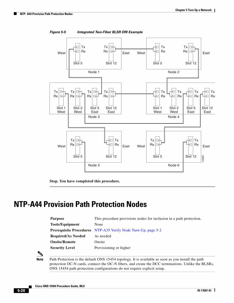
• The two interconnect nodes must have the correct fiber connections. Figure 5-5 shows an example of an integrated two-fiber BLSR DRI configuration.
Purpose This procedure provisions BLSRs in an integrated DRI topology.
Tools/Equipment None
Prerequisite Procedures NTP-A35 Verify Node Turn-Up, page 5-2
Required/As Needed As needed
Onsite/Remote Onsite
Security Level Provisioning or higher
5-19Cisco ONS 15454 Procedure Guide, R8.0
78-17697-01
Chapter 5 Turn Up a NetworkNTP- A44 Provision Path Protection Nodes
Figure 5-5 Integrated Two-Fiber BLSR DRI Example
Stop. You have completed this procedure.
NTP-A44 Provision Path Protection Nodes
Note Path Protection is the default ONS 15454 topology. It is available as soon as you install the path protection OC-N cards, connect the OC-N fibers, and create the DCC terminations. Unlike the BLSRs, ONS 15454 path protection configurations do not require explicit setup.
Node 1
West East
West
West
West East
East
East
Slot 5
TxRx
Slot 12
TxRx
Node 3
Slot 2West
TxRx
Slot 1West
TxRx
Slot 12East
TxRx
Node 2
Slot 5
TxRx
Slot 12
TxRx
Node 4
Slot 1West
TxRx
Slot 2West
TxRx
1152
57
Node 5
Slot 5
TxRx
Slot 12
TxRx
Slot 5East
TxRx
Slot 5East
TxRx
Slot 12East
TxRx
Node 6
Slot 5
TxRx
Slot 12
TxRx
Purpose This procedure provisions nodes for inclusion in a path protection.
Tools/Equipment None
Prerequisite Procedures NTP-A35 Verify Node Turn-Up, page 5-2
Required/As Needed As needed
Onsite/Remote Onsite
Security Level Provisioning or higher
5-20Cisco ONS 15454 Procedure Guide, R8.0
78-17697-01

Chapter 5 Turn Up a NetworkNTP- A44 Provision Path Protection Nodes
Step 1 Verify that the fiber is correctly connected to the path protection trunk (span) OC-N cards similar to Figure 5-6. See the “DLP-A43 Install Fiber-Optic Cables for Path Protection Configurations” task on page 17-44.
Figure 5-6 Path Protection Fiber Connection Example
Step 2 Log into an ONS 15454 in the path protection you are turning up. See the “DLP-A60 Log into CTC” task on page 17-60. If you are already logged in, continue with Step 3.
Step 3 Complete the “DLP-A377 Provision Section DCC Terminations” task on page 20-68 for the two cards/ports that will serve as the path protection ports on the node, for example, Slot 5 (OC-48)/Node 1 and Slot 12 (OC-48)/Node 1. (Alternatively, if additional bandwidth is needed for CTC management, complete the “DLP-A378 Provision Line DCC Terminations” task on page 20-70.)
Note If an ONS 15454 is not connected to a corporate LAN, DCC or LDCC provisioning must be performed through a direct (craft) connection. Remote provisioning is possible only after all nodes in the network have DCC or LDCC terminations provisioned to in-service OC-N ports.
Step 4 Repeat Steps 2 and 3 for each node in the path protection.
Step 5 As needed, complete the “DLP-A380 Provision a Proxy Tunnel” task on page 20-76.
Step 6 As needed, complete the “DLP-A381 Provision a Firewall Tunnel” task on page 20-77.
Step 7 As needed, complete the “DLP-A367 Create a Provisionable Patchcord” task on page 20-50.
Step 8 Complete the “NTP-A177 Path Protection Acceptance Test” procedure on page 5-22.
Stop. You have completed this procedure.
6812
0
Node 1
Slot 5
TxRx
Slot 12
TxRx
Node 4
Slot 5
TxRx
Slot 12
TxRx
Node 2
Slot 5
TxRx
Slot 12
TxRx
Node 3
Slot 5
TxRx
Slot 12
TxRx
5-21Cisco ONS 15454 Procedure Guide, R8.0
78-17697-01

Chapter 5 Turn Up a NetworkNTP- A177 Path Protection Acceptance Test
NTP-A177 Path Protection Acceptance Test
Caution This procedure might be service affecting if performed on a node carrying traffic.
Step 1 Complete the “DLP-A60 Log into CTC” task on page 17-60 at one of the ONS 15454s on the path protection you are testing. If you are already logged in, continue with Step 2.
Step 2 From the View menu, choose Go to Network View.
Step 3 Click the Alarms tab.
a. Verify that the alarm filter is not on. See the “DLP-A227 Disable Alarm Filtering” task on page 19-18 as necessary.
b. Verify that no unexplained alarms appear on the network. If unexplained alarms appear, resolve them before continuing. Refer to the Cisco ONS 15454 Troubleshooting Guide if necessary.
c. Complete the “DLP-A532 Export CTC Data” task on page 22-32 to export the alarm information.
Step 4 Click the Conditions tab.
a. Verify that no unexplained conditions appear on the network. If unexplained conditions appear, resolve them before continuing. Refer to the Cisco ONS 15454 Troubleshooting Guide if necessary.
b. Complete the “DLP-A532 Export CTC Data” task on page 22-32 to export the conditions information.
Step 5 On the network map, double-click the node that you logged into in Step 1.
Step 6 Create a test circuit from that node to the next adjacent path protection node.
• For DS-1 circuits, complete the “NTP-A181 Create an Automatically Routed DS-1 Circuit” procedure on page 6-7. When you set the circuit state, choose IS and check the Apply to drop ports check box.
• For DS-3 circuits, complete the “NTP-A184 Create an Automatically Routed DS-3 or EC-1 Circuit” procedure on page 6-19. When you set the circuit state, choose IS and check the Apply to drop ports check box.
• For OC-N circuits, complete the “NTP-A343 Create an Automatically Routed Optical Circuit” procedure on page 6-40. When you set the circuit state, choose IS and check the Apply to drop ports check box.
Step 7 Configure the test set for the test circuit type you created:
• DS-1—If you are testing a DS-1 that is not multiplexed, you must have a DSX-1 panel or a direct DS-1 interface into the ONS 15454. Set the test set for DS-1. For information about configuring your test set, consult your test set user guide.
Purpose This procedure tests a path protection.
Tools/Equipment Test set and cables appropriate to the test circuit you will create.
Prerequisite Procedures NTP-A44 Provision Path Protection Nodes, page 5-20
Required/As Needed As needed
Onsite/Remote Onsite
Security Level Provisioning or higher
5-22Cisco ONS 15454 Procedure Guide, R8.0
78-17697-01
Chapter 5 Turn Up a NetworkNTP- A177 Path Protection Acceptance Test
• DS-3—If you are testing a clear channel DS-3, you must have a DSX-3 panel or a direct DS-3 interface into the ONS 15454. Set the test set for clear channel DS-3. For information about configuring your test set, consult your test set user guide.
• DS3XM—If you are testing a DS-1 circuit on a DS3XM-6 or a DS3XM-12 card you must have a DSX-3 panel or a direct DS-3 interface to the ONS 15454. Set the test set for a multiplexed DS-3, then choose the DS-1 to test on the multiplexed DS-3. For information about configuring your test set, consult your test set user guide.
• OC-N—If you are testing an OC-N circuit, set the test set for the applicable circuit size. For information about configuring your test set, consult your test set user guide.
Step 8 Verify the integrity of all patch cables that will be used in this test by connecting one end to the test set Tx connector and the other end to the test set Rx connector. If the test set does not run error-free, check the cable for damage and check the test set to make sure it is set up correctly before continuing.
Step 9 Create a physical loopback at the circuit destination card:
a. Attach one end of a patch cable to the destination port’s Tx connector.
b. Attach the other end to the port’s Rx connector.
Step 10 At the circuit source card:
a. Connect the Tx connector of the test set to the circuit Rx connector.
b. Connect the test set Rx connector to the circuit Tx connector.
Step 11 Verify that the test set has a clean signal. If a clean signal does not appear, repeat Steps 6 through 10 to make sure the test set and cabling are configured correctly.
Step 12 Inject BIT errors from the test set. To verify that you have a complete end-to-end circuit, verify that the errors appear at the test set.
Step 13 Complete the “DLP-A356 TCC2/TCC2P Card Active/Standby Switch Test” task on page 20-39.
Step 14 Complete the “DLP-A255 Cross-Connect Card Side Switch Test” task on page 19-37.
Step 15 From the View menu, choose Go to Network View.
Step 16 Click one of the two spans leaving the circuit source node.
Step 17 Complete the “DLP-A94 Path Protection Protection Switching Test” task on page 17-90 to test the path protection switching function on this span.
Step 18 In network view, click the other circuit source span and repeat Step 17.
Step 19 Set up and complete a BER test. Use the existing configuration and follow your site requirements for the length of time. Record the test results and configuration.
Step 20 Complete the “DLP-A333 Delete Circuits” task on page 20-20 for the test circuit.
Step 21 Remove any loopbacks, switches, or test sets from the nodes after all testing is complete.
Step 22 Click the Alarms tab.
a. Verify that the alarm filter is not on. See the “DLP-A227 Disable Alarm Filtering” task on page 19-18 as necessary.
b. Verify that no unexplained alarms appear on the network. If unexplained alarms appear, resolve them before continuing. Refer to the Cisco ONS 15454 Troubleshooting Guide if necessary.
c. Complete the “DLP-A532 Export CTC Data” task on page 22-32 to export the alarm information.
Step 23 Click the Conditions tab.
a. Verify that no unexplained conditions appear on the network. If unexplained conditions appear, resolve them before continuing. Refer to the Cisco ONS 15454 Troubleshooting Guide if necessary.
5-23Cisco ONS 15454 Procedure Guide, R8.0
78-17697-01

Chapter 5 Turn Up a NetworkNTP- A216 Provision a Traditional Path Protection Dual-Ring Interconnect
b. Complete the “DLP-A532 Export CTC Data” task on page 22-32 to export the conditions information.
Step 24 Repeat Steps 5 through 23 for each node on the network.
Step 25 If a node fails any test, repeat the test while verifying correct setup and configuration. If the test fails again, refer to the next level of support.
After all tests are successfully completed and no alarms exist in the network, the network is ready for service application. Continue with Chapter 6, “Create Circuits and VT Tunnels.”
Stop. You have completed this procedure.
NTP-A216 Provision a Traditional Path Protection Dual-Ring Interconnect
Note To route circuits on the DRI, you must check the Dual Ring Interconnect check box during circuit creation.
Step 1 Complete the “DLP-A60 Log into CTC” task on page 17-60. If you are already logged in, continue with Step 2.
Step 2 Complete the following steps if you have not provisioned the path protection configurations that you will interconnect in a path protection DRI. If the path protection configurations are created, go to Step 3.
a. Complete the “NTP-A44 Provision Path Protection Nodes” procedure on page 5-20 to provision the path protection configurations.
b. Complete the “NTP-A177 Path Protection Acceptance Test” procedure on page 5-22 to test the path protection configurations.
Note All path protection configurations that will be interconnected must have the same OC-N rate.
Step 3 Verify that the path protection DRI interconnect nodes have OC-N cards installed and have fiber connections to the other interconnect node:
• The OC-N cards that will connect the path protection configurations must be installed at the interconnect nodes. The OC-N cards in the path protection nodes and the interconnect nodes must be the same type.
Purpose This procedure provisions path protection configurations in a traditional DRI topology. DRIs interconnect two or more path protection configurations to provide an additional level of protection.
Tools/Equipment None
Prerequisite Procedures NTP-A35 Verify Node Turn-Up, page 5-2
Required/As Needed As needed
Onsite/Remote Onsite
Security Level Provisioning or higher
5-24Cisco ONS 15454 Procedure Guide, R8.0
78-17697-01

Chapter 5 Turn Up a NetworkNTP- A216 Provision a Traditional Path Protection Dual-Ring Interconnect
• The interconnect nodes must have fiber connections. An example is shown in Figure 5-7. This example shows a path protection DRI with two rings, Nodes 1 through 4 and 5 through 8. In the example, an additional OC-N is installed in Slot 13 at Node 4 and connected to an OC-N in Slot 6 at Node 6. Nodes 3 and 5 are interconnected with OC-N cards in Slot 6 (Node 3) and Slot 13 (Node 5).
Figure 5-7 Traditional Path Protection DRI Fiber Connection Example
Stop. You have completed this procedure.
Node 1
Slot 5
TxRx
Slot 12
TxRx
Node 3
Slot 5
TxRx
Slot 12
TxRx
Node 2
Slot 5
TxRx
Slot 12
TxRx
Node 4
Slot 5
TxRx
Slot 12
TxRx
8349
9
Node 5
Slot 5
TxRx
Slot 12
TxRx
Node 7
Slot 5
TxRx
Slot 12
TxRx
Node 6
Slot 5
TxRx
Slot 6
TxRx
Slot 13
TxRx
Slot 13
TxRx
Slot 6
TxRx
Slot 12
TxRx
Node 8
Slot 5
TxRx
Slot 12
TxRx
5-25Cisco ONS 15454 Procedure Guide, R8.0
78-17697-01

Chapter 5 Turn Up a NetworkNTP- A217 Provision an Integrated Path Protection Dual-Ring Interconnect
NTP-A217 Provision an Integrated Path Protection Dual-Ring Interconnect
Step 1 Complete the “DLP-A60 Log into CTC” task on page 17-60 at a node in the path protection DRI network. If you are already logged in, continue with Step 2.
Step 2 Complete the following steps if you have not provisioned the path protection configurations that you will interconnect in a path protection DRI. If the path protection configurations are created, continue with Step 3.
a. Complete the “NTP-A44 Provision Path Protection Nodes” procedure on page 5-20 to provision the path protection configurations.
b. Complete the “NTP-A177 Path Protection Acceptance Test” procedure on page 5-22 to test the path protection configurations.
Note All path protection configurations that will be interconnected must have the same OC-N rate.
Step 3 Verify that the path protection DRI interconnect nodes have OC-N cards installed and have fiber connections to the other interconnect node:
• The OC-N cards that will connect the path protection configurations must be installed at the interconnect nodes. The OC-N cards in the path protection nodes and the interconnect nodes must be the same type.
• The interconnect nodes must have the correct fiber connections. An example is shown in Figure 5-8. This example shows a path protection DRI with two rings.
Purpose This procedure provisions path protection configurations in an integrated DRI topology. In the integrated DRI, the path protection OC-N trunk cards for both path protection configurations are installed on the same shelf.
Tools/Equipment None
Prerequisite Procedures NTP-A35 Verify Node Turn-Up, page 5-2
Required/As Needed As needed
Onsite/Remote Onsite
Security Level Provisioning or higher
5-26Cisco ONS 15454 Procedure Guide, R8.0
78-17697-01

Chapter 5 Turn Up a NetworkNTP- A180 Provision a Traditional BLSR/Path Protection Dual-Ring Interconnect
Figure 5-8 Integrated Path Protection DRI Example
Stop. You have completed this procedure.
NTP-A180 Provision a Traditional BLSR/Path Protection Dual-Ring Interconnect
Node 1
Node 3
Node 2
Node 4
Slot5
Slot12
TxRx
Slot5
Slot12
TxRx
Slot6
Slot13
Slot5
Slot12
TxRx
Slot5
Slot12
TxRx
Slot6
Slot13
Node 5 Node 6
Slot5
Slot12
TxRx
Slot5
Slot12
TxRx
8350
0
Purpose This procedure provisions a BLSR and a path protection in a traditional DRI topology. DRIs interconnect ring topologies to provide an additional level of protection.
Tools/Equipment None
Prerequisite Procedures NTP-A35 Verify Node Turn-Up, page 5-2
Required/As Needed As needed
Onsite/Remote Onsite
Security Level Provisioning or higher
5-27Cisco ONS 15454 Procedure Guide, R8.0
78-17697-01

Chapter 5 Turn Up a NetworkNTP- A180 Provision a Traditional BLSR/Path Protection Dual-Ring Interconnect
Note To route circuits on the DRI, you must check the Dual Ring Interconnect check box during circuit creation.
Step 1 Complete the “DLP-A60 Log into CTC” task on page 17-60. If you are already logged in, continue with Step 2.
Step 2 Complete the following steps if you have not provisioned the BLSR and path protection that you will interconnect in a traditional DRI. If the BLSR and path protection are created, go to Step 3.
a. To provision and test the BLSR, complete the following procedures:
• NTP-A40 Provision BLSR Nodes, page 5-10
• NTP-A126 Create a BLSR, page 5-12
• NTP-A175 Two-Fiber BLSR Acceptance Test, page 5-12
• NTP-A176 Four-Fiber BLSR Acceptance Test, page 5-14
b. To provision and test the path protection, complete the following procedures:
• NTP-A44 Provision Path Protection Nodes, page 5-20
• NTP-A177 Path Protection Acceptance Test, page 5-22
Step 3 Verify that the DRI interconnect nodes have OC-N cards installed and have fiber connections to the other interconnect node:
• The OC-N cards that will connect the BLSR and path protection must be installed at the interconnect nodes. The OC-N cards in the path protection nodes and the interconnect nodes must be the same type.
• The interconnect nodes must have fiber connections. An example is shown in Figure 5-9.
5-28Cisco ONS 15454 Procedure Guide, R8.0
78-17697-01

Chapter 5 Turn Up a NetworkNTP- A180 Provision a Traditional BLSR/Path Protection Dual-Ring Interconnect
Figure 5-9 Traditional BLSR to Path Protection DRI Fiber Connection Example
Stop. You have completed this procedure.
Node 1
West East
West East
West East
West
West
West
West
West East
East
BLSR Ring
Ring
East
East
East
Slot 5
TxRx
Slot 12
TxRx
Node 4
Slot 1
TxRx
Slot 12
TxRx
Node 2
Slot 5
TxRx
Slot 12
TxRx
Node 3
Slot 1
TxRx
Slot 5
TxRx
1152
69
Node 5
Slot 5
TxRx
Slot 6
TxRx
Node 8
Slot 5
TxRx
Slot 12
TxRx
Node 6
Slot 5
TxRx
Slot 5
TxRx
Slot 12
TxRx
Slot 12
TxRx
Slot 6
TxRx
Slot 12
TxRx
Node 7
Slot 5
TxRx
Slot 12
TxRx
5-29Cisco ONS 15454 Procedure Guide, R8.0
78-17697-01

Chapter 5 Turn Up a NetworkNTP- A209 Provision an Integrated BLSR/Path Protection Dual-Ring Interconnect
NTP-A209 Provision an Integrated BLSR/Path Protection Dual-Ring Interconnect
Step 1 Complete the “DLP-A60 Log into CTC” task on page 17-60 at a node in the BLSR and path protection DRI network. If you are already logged in, continue with Step 2.
Step 2 Complete the following steps if you have not provisioned the BLSR and path protection that you will interconnect in an integrated DRI. If the BLSR and path protection are created, continue with Step 3.
a. To provision and test the BLSR, complete the following procedures:
• NTP-A40 Provision BLSR Nodes, page 5-10
• NTP-A126 Create a BLSR, page 5-12
• NTP-A175 Two-Fiber BLSR Acceptance Test, page 5-12
• NTP-A176 Four-Fiber BLSR Acceptance Test, page 5-14
b. To provision and test the path protection, complete the following procedures:
• NTP-A44 Provision Path Protection Nodes, page 5-20
• NTP-A177 Path Protection Acceptance Test, page 5-22
Step 3 Verify that the BLSR and path protection DRI interconnect nodes have OC-N cards installed and have fiber connections to the other interconnect node:
• The OC-N cards that will connect the BLSR and path protection must be installed at the interconnect nodes. The OC-N cards in the path protection nodes and the interconnect nodes must be the same type.
• The interconnect nodes must have the correct fiber connections. An example is shown in Figure 5-10.
Purpose This procedure provisions a BLSR and a path protection in an integrated DRI topology.
Tools/Equipment None
Prerequisite Procedures NTP-A35 Verify Node Turn-Up, page 5-2
Required/As Needed As needed
Onsite/Remote Onsite
Security Level Provisioning or higher
5-30Cisco ONS 15454 Procedure Guide, R8.0
78-17697-01

Chapter 5 Turn Up a NetworkNTP- A224 Provision an Open-Ended Path Protection
Figure 5-10 Integrated BLSR to Path Protection DRI Example
Stop. You have completed this procedure.
NTP-A224 Provision an Open-Ended Path Protection
Node 1
West WestEast
WestEast
East
West East
BLSR Ring
Ring
Node 4
Node 2
Node 3
Slot 5 Slot 12
TxRx
Slot 2Slot 1 Slot 5
TxRx
Slot 12
Slot 5 Slot 12
TxRx
Slot 1
TxRx
Slot 2 Slot 5 Slot 12
Node 1 Node 2
Slot 5 Slot 12
TxRx
TxRx
TxRx
Slot 5 Slot 12
TxRx
TxRx
TxRx
1152
74
Purpose This procedure provisions ONS 15454 nodes in an open-ended path protection connected to a third-party vendor network. This topology allows you to route a circuit from one ONS 15454 network to another ONS 15454 network through the third-party network.
Tools/Equipment None
Prerequisite Procedures NTP-A35 Verify Node Turn-Up, page 5-2
Required/As Needed As needed
Onsite/Remote Onsite
Security Level Provisioning or higher
5-31Cisco ONS 15454 Procedure Guide, R8.0
78-17697-01

Chapter 5 Turn Up a NetworkNTP- A224 Provision an Open-Ended Path Protection
Step 1 Verify that the fiber is correctly connected to the path protection trunk (span) OC-N cards at each open-ended path protection node. Figure 5-11 shows an example. Node 1 is connected to ONS 15454 Nodes 2 and 3 through Slots 12 and 5. Trunk cards at Nodes 2 and 3 are connected to the third-party vendor equipment.
Figure 5-11 ONS 15454 Open-Ended Path Protections Fiber Connection Example
Step 2 Verify that the third-party cards to which the ONS 15454 trunk cards are connected are the same OC-N rate as the ONS 15454 trunk cards. The third-party time slots must match the ONS 15454 card time slots to which they are connected. For example, if your trunk card is an OC-48, the third-party vendor card or unit must have STSs 1 to 48 available.
Step 3 Log into an ONS 15454 in the path protection you are turning up. See the “DLP-A60 Log into CTC” task on page 17-60. If you are already logged in, continue with Step 4.
Step 4 Complete the “DLP-A377 Provision Section DCC Terminations” task on page 20-68 for the ONS 15454 cards/ports that are connected to another ONS 15454. (Alternatively, if additional bandwidth is needed for CTC management, complete the“DLP-A378 Provision Line DCC Terminations” task on
9648
8
Node 2
Slot 5
TxRx
Slot 12
TxRx
Node 1
Slot 5
TxRx
Slot 12
TxRx
Node 6
Slot 5
TxRx
Slot 12
TxRx
Node 4
Slot 5
TxRx
Slot 12
TxRx
Node 3
Slot 5
TxRx
Slot 12
TxRx
Node 5
Slot 5
TxRx
Slot 12
TxRx
Third PartyNetwork
5-32Cisco ONS 15454 Procedure Guide, R8.0
78-17697-01

Chapter 5 Turn Up a NetworkNTP- A225 Open-Ended Path Protection Acceptance Test
page 20-70.) Do not create DCC or LDCC terminations for the card/port that connects to the third-party equipment. For example in Figure 5-11 on page 5-32, DCC terminations are created at the following cards/ports:
• Nodes 1 and 6: Slot 5 and Slot 12
• Node 2 and 5: Slot 12
• Node 3 and 4: Slot 5
Note If an ONS 15454 is not connected to a corporate LAN, DCC or LDCC provisioning must be performed through a direct (craft) connection. Remote provisioning is possible only after all nodes in the network have DCC or LDCC terminations provisioned to in-service OC-N ports.
Step 5 Repeat Steps 3 and 4 for each node in the path protection.
Step 6 As needed, complete the “DLP-A380 Provision a Proxy Tunnel” task on page 20-76.
Step 7 As needed, complete the “DLP-A381 Provision a Firewall Tunnel” task on page 20-77.
Step 8 Following the documentation provided by the third-party vendor, provision the optical loop leading from the ONS 15454 connection at one end to the ONS 15454 connection at the other end. In other words, you will create an open-ended path protection using procedures for the third-party equipment.
Step 9 Complete the “NTP-A225 Open-Ended Path Protection Acceptance Test” procedure on page 5-33.
Stop. You have completed this procedure.
NTP-A225 Open-Ended Path Protection Acceptance Test
Caution This procedure might be service affecting if performed on a node carrying traffic.
Step 1 Complete the “DLP-A60 Log into CTC” task on page 17-60 at the node that will be the source node for traffic traversing the third-party network. If you are already logged in, continue with Step 2.
Step 2 From the View menu, choose Go to Network View.
Step 3 Click the Alarms tab.
a. Verify that the alarm filter is not on. See the “DLP-A227 Disable Alarm Filtering” task on page 19-18 as necessary.
b. Verify that no unexplained alarms appear on the network. If unexplained alarms appear, resolve them before continuing. Refer to the Cisco ONS 15454 Troubleshooting Guide if necessary.
c. Complete the “DLP-A532 Export CTC Data” task on page 22-32 to export the alarm information.
Purpose This procedure tests an open-ended path protection.
Tools/Equipment Test set and cables appropriate to the test circuit you will create.
Prerequisite Procedures NTP-A224 Provision an Open-Ended Path Protection, page 5-31
Required/As Needed As needed
Onsite/Remote Onsite
Security Level Provisioning or higher
5-33Cisco ONS 15454 Procedure Guide, R8.0
78-17697-01

Chapter 5 Turn Up a NetworkNTP- A225 Open-Ended Path Protection Acceptance Test
Step 4 Click the Conditions tab.
a. Verify that no unexplained conditions appear on the network. If unexplained conditions appear, resolve them before continuing. Refer to the Cisco ONS 15454 Troubleshooting Guide if necessary.
b. Complete the “DLP-A532 Export CTC Data” task on page 22-32 to export the conditions information.
Step 5 On the network map, double-click the node that you logged into in Step 1.
Step 6 Create a test circuit from that node to the OC-N trunk (span) cards on the nodes that connect to the third-party network. For example, in Figure 5-11 on page 5-32, a circuit is created from Node 1 to the Slot 5 OC-N card at Node 2, and a secondary circuit destination is created on the Slot 12 OC-N card at Node 3. For circuit creation procedures, complete one of the following:
• For DS-1 circuits, complete the “NTP-A181 Create an Automatically Routed DS-1 Circuit” procedure on page 6-7. When you set the circuit state, choose IS and check the Apply to drop ports check box.
• For DS-3 circuits, complete the “NTP-A184 Create an Automatically Routed DS-3 or EC-1 Circuit” procedure on page 6-19. When you set the circuit state, choose IS and check the Apply to drop ports check box.
• For OC-N circuits, complete the “NTP-A343 Create an Automatically Routed Optical Circuit” procedure on page 6-40. When you set the circuit state, choose IS and check the Apply to drop ports check box.
Step 7 Create a circuit within the third-party network from ONS 15454 connection ports to the second set of ONS 15454 connection ports on both path protection spans. Refer to the third-party equipment documentation for circuit creation procedures.
Step 8 Repeat Step 6 to create a second circuit at the terminating node on the other side of the third-party network. In Figure 5-11, this is Node 6. However, this circuit will have two sources, one at Node 4/Slot 12, and one at Node 5/Slot 5. The destination will be a drop card on Node 6.
Step 9 Configure the test set for the test circuit type you created:
• DS-1—If you are testing a DS-1 that is not multiplexed, you must have a DSX-1 panel or a direct DS-1 interface into the ONS 15454. Set the test set for DS-1. For information about configuring your test set, consult your test set user guide.
• DS-3—If you are testing a clear channel DS-3, you must have a DSX-3 panel or a direct DS-3 interface into the ONS 15454. Set the test set for clear channel DS-3. For information about configuring your test set, consult your test set user guide.
• DS3XM—If you are testing a DS-1 circuit on a DS3XM-6 or DS3XM-12 card you must have a DSX-3 panel or a direct DS-3 interface to the ONS 15454. Set the test set for a multiplexed DS-3, then choose the DS-1 to test on the multiplexed DS-3. For information about configuring your test set, consult your test set user guide.
• OC-N—If you are testing an OC-N circuit, set the test set for the applicable circuit size. For information about configuring your test set, consult your test set user guide.
Step 10 Verify the integrity of all patch cables that will be used in this test by connecting one end to the test set Tx connector and the other end to the test set Rx connector. If the test set does not run error-free, check the cable for damage and check the test set to make sure it is set up correctly before continuing.
Step 11 Create a physical loopback at the circuit destination card:
a. Attach one end of a patch cable to the destination port’s Tx connector.
b. Attach the other end to the port’s Rx connector.
5-34Cisco ONS 15454 Procedure Guide, R8.0
78-17697-01

Chapter 5 Turn Up a NetworkNTP- A225 Open-Ended Path Protection Acceptance Test
Step 12 At the circuit source card:
a. Connect the Tx connector of the test set to the circuit Rx connector.
b. Connect the test set Rx connector to the circuit Tx connector.
Step 13 Verify that the test set shows a clean signal. If a clean signal does not appear, repeat Steps 6 through 12 to make sure the test set and cabling are configured correctly.
Step 14 Inject BIT errors from the test set. To verify that you have a complete end-to-end circuit, verify that the errors appear at the test set.
Step 15 Complete the “DLP-A356 TCC2/TCC2P Card Active/Standby Switch Test” task on page 20-39.
Step 16 Complete the “DLP-A255 Cross-Connect Card Side Switch Test” task on page 19-37.
Although a service interruption under 60 ms might occur, the test circuit should continue to work before, during, and after the switches. If the circuit stops working, do not continue. Contact your next level of support.
Step 17 From the View menu, choose Go to Network View.
Step 18 Click one of the two spans leaving the circuit source node.
Step 19 Complete the “DLP-A94 Path Protection Protection Switching Test” task on page 17-90 to test the path protection switching function on this span.
Step 20 In network view, click the other circuit source span and repeat Step 19.
Step 21 Set up and complete a BER test. Use the existing configuration and follow your site requirements for the length of time. Record the test results and configuration.
Step 22 Complete the “DLP-A333 Delete Circuits” task on page 20-20 for the test circuit.
Step 23 Remove any loopbacks, switches, or test sets from the nodes after all testing is complete.
Step 24 In network view, click the Alarms tab.
a. Verify that the alarm filter is not on. See the “DLP-A227 Disable Alarm Filtering” task on page 19-18 as necessary.
b. Verify that no unexplained alarms appear on the network. If unexplained alarms appear, resolve them before continuing. Refer to the Cisco ONS 15454 Troubleshooting Guide if necessary.
c. Complete the “DLP-A532 Export CTC Data” task on page 22-32 to export the alarm information.
Step 25 In network view, click the Conditions tab.
a. Verify that no unexplained conditions appear on the network. If unexplained conditions appear, resolve them before continuing. Refer to the Cisco ONS 15454 Troubleshooting Guide if necessary.
b. Complete the “DLP-A532 Export CTC Data” task on page 22-32 to export the conditions information.
Step 26 Repeat Steps 6 through 25 for each node that will be a source or destination for circuits traversing the third-party network.
Step 27 If a node fails any test, repeat the test while verifying correct setup and configuration. If the test fails again, refer to the next level of support.
After all tests are successfully completed and no alarms exist in the network, the network is ready for service application. Continue with Chapter 6, “Create Circuits and VT Tunnels.”
Stop. You have completed this procedure.
5-35Cisco ONS 15454 Procedure Guide, R8.0
78-17697-01

Chapter 5 Turn Up a NetworkNTP- A46 Subtend a Path Protection from a BLSR
NTP-A46 Subtend a Path Protection from a BLSR
Note Path Protection is the default ONS 15454 topology. It is available as soon as you install the path protection OC-N cards, connect the OC-N fibers, and create the DCC terminations. Unlike the BLSRs, ONS 15454 path protections do not require explicit setup.
Step 1 In the node that will subtend the path protection , install the two OC-N cards that will serve as the path protection trunk (span) cards (Node 3, Slots 6 and 13). See the “NTP-A16 Install Optical Cards and Connectors” procedure on page 2-7. If they are already installed, continue with Step 2.
Step 2 Attach fibers from these cards to the path protection trunk cards on the neighbor path protection node or nodes. Complete the “DLP-A60 Log into CTC” task on page 17-60 at the ONS 15454 that will subtend the path protection (Node 3 in the example).
Step 3 Complete the “DLP-A377 Provision Section DCC Terminations” task on page 20-68 for each OC-N card that will carry the path protection. Alternatively, if additional bandwidth is needed for CTC management, complete the“DLP-A378 Provision Line DCC Terminations” task on page 20-70.
Step 4 Log into a path protection node that connects to the node in Step 2.
Step 5 Complete the “DLP-A377 Provision Section DCC Terminations” task on page 20-68 for each OC-N card that will carry the path protection. Alternatively, if additional bandwidth is needed for CTC management, complete the“DLP-A378 Provision Line DCC Terminations” task on page 20-70.
Step 6 Repeat Step 5 for each node in the path protection.
Step 7 As needed, complete the “DLP-A380 Provision a Proxy Tunnel” task on page 20-76.
Step 8 As needed, complete the “DLP-A381 Provision a Firewall Tunnel” task on page 20-77.
Step 9 From the View menu, choose Go To Network View to view the subtending rings.
Step 10 Complete the “NTP-A177 Path Protection Acceptance Test” procedure on page 5-22.
Stop. You have completed this procedure.
NTP-A47 Subtend a BLSR from Path Protection
Purpose This procedure subtends a path protection from an existing BLSR.
Tools/Equipment One BLSR node must have OC-N cards and fibers to carry the path protection.
Prerequisite Procedures NTP-A175 Two-Fiber BLSR Acceptance Test, page 5-12 or NTP-A176 Four-Fiber BLSR Acceptance Test, page 5-14
Required/As Needed As needed
Onsite/Remote Onsite
Security Level Provisioning or higher
Purpose This procedure subtends a BLSR from an existing path protection.
Tools/Equipment One path protection node must have OC-N cards and fibers to carry the BLSR
5-36Cisco ONS 15454 Procedure Guide, R8.0
78-17697-01

Chapter 5 Turn Up a NetworkNTP- A48 Subtend a BLSR from a BLSR
Step 1 In the path protection node that will subtend the BLSR, install the two OC-N cards that will serve as the BLSR trunk (span) cards See the “NTP-A16 Install Optical Cards and Connectors” procedure on page 2-7.
Step 2 Attach fibers from the cards in Step 1 to the BLSR trunk cards on another BLSR node or nodes. In Slot 5/Node 3 connects to Slot 12/Node 2, and Slot 12/Node 3 connects to Slot 5/Node 1.
Step 3 Log into the ONS 15454 that will subtend the BLSR (the node in Step 1). See the “DLP-A60 Log into CTC” task on page 17-60. If you are already logged in, continue with Step 4.
Step 4 Create the DCCs on both OC-N trunk cards (east and west) that will carry the BLSR. See the “DLP-A377 Provision Section DCC Terminations” task on page 20-68. Alternatively, if additional bandwidth is needed for CTC management, complete the “DLP-A378 Provision Line DCC Terminations” task on page 20-70.
Step 5 Create the subtending BLSR:
a. Complete the “NTP-A40 Provision BLSR Nodes” procedure on page 5-10 for each node that will be in the BLSR. If you have already provisioned the BLSR, perform this procedure for the subtending node only.
b. Complete the “NTP-A126 Create a BLSR” procedure on page 5-12. Include the node in Step 3 (the node that will subtend the BLSR) in the BLSR.
Step 6 From the View menu, choose Go to the Network View to see the subtending ring.
Stop. You have completed this procedure.
NTP-A48 Subtend a BLSR from a BLSR
Note This procedure assumes that all nodes are configured for the BLSR. If you need to add a node to a BLSR, see the “NTP-A350 Add a BLSR Node” procedure on page 14-1.
Step 1 Complete the “DLP-A60 Log into CTC” task on page 17-60 at the node that will subtend the BLSR (Node 4 in Figure 5-12). If you are already logged in, continue with Step 2.
Prerequisite Procedures NTP-A177 Path Protection Acceptance Test, page 5-22
Required/As Needed As needed
Onsite/Remote Onsite
Security Level Provisioning or higher
Purpose This procedure subtends a BLSR from an existing BLSR.
Tools/Equipment One BLSR node must have OC-N cards and fibers needed to carry the second BLSR.
Prerequisite Procedures None
Required/As Needed As needed
Onsite/Remote Onsite
Security Level Provisioning or higher
5-37Cisco ONS 15454 Procedure Guide, R8.0
78-17697-01

Chapter 5 Turn Up a NetworkNTP- A48 Subtend a BLSR from a BLSR
Step 2 Install the OC-N cards that will serve as the BLSR trunk (span) cards if they are not already installed. See the “NTP-A16 Install Optical Cards and Connectors” procedure on page 2-7.
Figure 5-12 shows two BLSRs shared by one ONS 15454. Ring 1 runs on Nodes 1, 2, 3, and 4. Ring 2 runs on Nodes 4, 5, 6, and 7 and represents the subtending ring added by this procedure. Two BLSR rings, Ring 1 and Ring 2, are provisioned on Node 4. Ring 1 uses cards in Slots 5 and 12, and Ring 2 uses cards in Slots 6 and 13.
Figure 5-12 BLSR Subtended from a BLSR
Step 3 Attach fibers from the trunk cards in the subtending node to the BLSR trunk cards on its two neighboring BLSR nodes. In Figure 5-12, Node 4/Slot 6 connects to Node 7/Slot 13, and Node 4/Slot 13 connects to Node 5/Slot 6. See the “DLP-A44 Install Fiber-Optic Cables for BLSR Configurations” task on page 17-47.
Step 4 Create the DCCs on the first OC-N card that will carry the BLSR. See the “DLP-A377 Provision Section DCC Terminations” task on page 20-68. Alternatively, if additional bandwidth is needed for CTC management, complete the“DLP-A378 Provision Line DCC Terminations” task on page 20-70.
Step 5 Repeat Step 4 for the second OC-N trunk card that will carry the BLSR.
Step 6 Complete the “NTP-A40 Provision BLSR Nodes” procedure on page 5-10 for each node that will be in the BLSR. If you have already provisioned the BLSR, perform this procedure for the subtending node only.
Step 7 If the subtending BLSR is not already created, complete the “NTP-A126 Create a BLSR” procedure on page 5-12 to provision the new BLSR. The subtending BLSR must have a ring name that differs from the ring name of the first BLSR.
Note The subtending node can have one Node ID that is used in both BLSRs, or a different Node ID for each BLSR. For example, the same node can be Node 4 in BLSR 1 and Node 2 in BLSR 2.
Step 8 From the View menu, choose Go to Network View to see the subtending ring.
Figure 5-13 shows an example of two subtending BLSRs.
5529
8
Node 5
Slot 6West
EastSlot 13
Node 7
Slot 13East
Slot 6West
Slot 6West
Slot 13East
Node 6
Node 1
Slot 5West
Slot 5West
Slot 12East
Slot 12East
Node 3
Slot 12East
Slot 5West
Node 2
Slot 5West
Slot 12East
Slot 13East
Slot 6West
Node 4
BLSRRing 1
BLSRRing 2
5-38Cisco ONS 15454 Procedure Guide, R8.0
78-17697-01
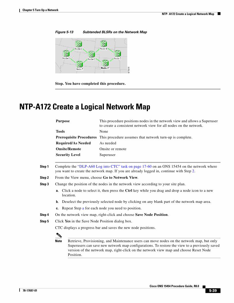
Chapter 5 Turn Up a NetworkNTP- A172 Create a Logical Network Map
Figure 5-13 Subtended BLSRs on the Network Map
Stop. You have completed this procedure.
NTP-A172 Create a Logical Network Map
Step 1 Complete the “DLP-A60 Log into CTC” task on page 17-60 on an ONS 15454 on the network where you want to create the network map. If you are already logged in, continue with Step 2.
Step 2 From the View menu, choose Go to Network View.
Step 3 Change the position of the nodes in the network view according to your site plan.
a. Click a node to select it, then press the Ctrl key while you drag and drop a node icon to a new location.
b. Deselect the previously selected node by clicking on any blank part of the network map area.
c. Repeat Step a for each node you need to position.
Step 4 On the network view map, right-click and choose Save Node Position.
Step 5 Click Yes in the Save Node Position dialog box.
CTC displays a progress bar and saves the new node positions.
Note Retrieve, Provisioning, and Maintenance users can move nodes on the network map, but only Superusers can save new network map configurations. To restore the view to a previously saved version of the network map, right-click on the network view map and choose Reset Node Position.
Purpose This procedure positions nodes in the network view and allows a Superuser to create a consistent network view for all nodes on the network.
Tools None
Prerequisite Procedures This procedure assumes that network turn-up is complete.
Required/As Needed As needed
Onsite/Remote Onsite or remote
Security Level Superuser
5-39Cisco ONS 15454 Procedure Guide, R8.0
78-17697-01

Chapter 5 Turn Up a NetworkNTP- A172 Create a Logical Network Map
Stop. You have completed this procedure.
5-40Cisco ONS 15454 Procedure Guide, R8.0
78-17697-01