TURF RAKES / SEEDERS – PARTS MANUAL
18
TURF RAKES / SEEDERS – PARTS MANUAL Schiller Grounds Care • 1028 Street Road • Southampton, PA 18966 Telephone 1.800.366.6268 • Teléfono + 877.596.6337 P/N C100618 REV A THIS MANUAL COVERS UNITS MANUFACTERED FROM 02/01/2012 TO PRESENT. ORIGINAL LANGUAGE INSTRUCTIONS TR-20H / TR-20B TURF RAKE TR-20MH / TR-20MB TURF RAKE w/ MULTI-PURPOSE BLADE TRC-20H / TRC-20B TURF RAKE w/ CATCHER TS-20H / TS-20B TURF SEEDER TR-20RH / TR-20RB TURF RAKE W/ SPRING TINE REEL
Transcript of TURF RAKES / SEEDERS – PARTS MANUAL

TURF RAKES / SEEDERS – PARTS MANUAL
Schiller Grounds Care • 1028 Street Road • Southampton, PA 18966 Telephone 1.800.366.6268 • Teléfono + 877.596.6337
P/N C100618 REV A THIS MANUAL COVERS UNITS MANUFACTERED FROM 02/01/2012 TO PRESENT.
ORIGINAL LANGUAGE INSTRUCTIONS
TR-20H / TR-20B TURF RAKE
TR-20MH / TR-20MB TURF RAKE w/ MULTI-PURPOSE BLADE
TRC-20H / TRC-20B TURF RAKE w/ CATCHER
TS-20H / TS-20B TURF SEEDER
TR-20RH / TR-20RB TURF RAKE W/ SPRING TINE REEL

2
TABLE OF CONTENTSSAFETY ........................................................................................................................................................................ 3-4MAINTENACE / STORAGE ............................................................................................................................................. 5PARTS SECTION ............................................................................................................................................................. 6DECALS ................................................................................. FIGURE 1 ........................................................................ 7TR-20 MAIN FRAME ASSY ................................................... FIGURE 2 ..................................................................... 8-9TR-20 RAKE BLADE ASSY .................................................. FIGURE 3 ...................................................................... 10TRC-20 CATCHER BAG ASSY ............................................. FIGURE 4 ...................................................................... 10TR-20M / TS-20M MULTIPURPOSE BLADE ASSY ............. FIGURE 5 .......................................................................11SLICER BLADE ASSEMBLY (OPTIONAL) .......................... FIGURE 6 .......................................................................11TR-20R SPRING TINE RELL ASSY ...................................... FIGURE 7 ...................................................................... 12TS-20 SEED BOX ASSY........................................................ FIGURE 8 ...................................................................... 13CONVERTING TR-20 TO TRC-20 ........................................ FIGURE 9 ...................................................................... 14SEEDER TIRE SCRAP ASSY ............................................... FIGURE 10 .................................................................... 15SEEDER BOX INSTALLATION ............................................. FIGURE 11 .................................................................... 15NOTES ........................................................................................................................................................................... 16WARRANTY ................................................................................................................................................................... 17
3
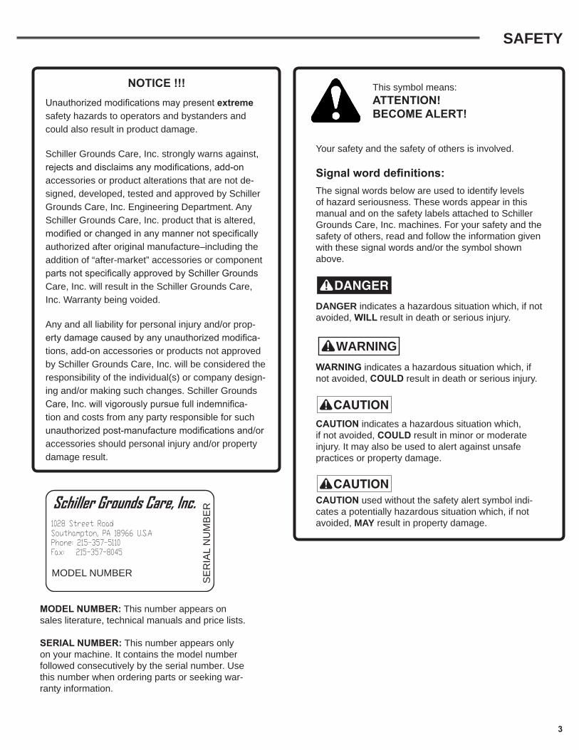
MODEL NUMBER: This number appears on sales literature, technical manuals and price lists.
SERIAL NUMBER: This number appears only on your machine. It contains the model number followed consecutively by the serial number. Use this number when ordering parts or seeking war-ranty information.
NOTICE !!!Unauthorized modifications may present extreme safety hazards to operators and bystanders and could also result in product damage.
Schiller Grounds Care, Inc. strongly warns against, rejects and disclaims any modifications, add-on accessories or product alterations that are not de-signed, developed, tested and approved by Schiller Grounds Care, Inc. Engineering Department. Any Schiller Grounds Care, Inc. product that is altered, modified or changed in any manner not specifically authorized after original manufacture–including the addition of “after-market” accessories or component parts not specifically approved by Schiller Grounds Care, Inc. will result in the Schiller Grounds Care, Inc. Warranty being voided.
Any and all liability for personal injury and/or prop-erty damage caused by any unauthorized modifica-tions, add-on accessories or products not approved by Schiller Grounds Care, Inc. will be considered the responsibility of the individual(s) or company design-ing and/or making such changes. Schiller Grounds Care, Inc. will vigorously pursue full indemnifica-tion and costs from any party responsible for such unauthorized post-manufacture modifications and/or accessories should personal injury and/or property damage result.
This symbol means: ATTENTION! BECOME ALERT!
Your safety and the safety of others is involved.
Signal word definitions:The signal words below are used to identify levels of hazard seriousness. These words appear in this manual and on the safety labels attached to Schiller Grounds Care, Inc. machines. For your safety and the safety of others, read and follow the information given with these signal words and/or the symbol shown above.
! DANGER indicates a hazardous situation which, if not avoided, WILL result in death or serious injury.
WARNING! WARNING indicates a hazardous situation which, if not avoided, COULD result in death or serious injury.
! CAUTION indicates a hazardous situation which, if not avoided, COULD result in minor or moderate injury. It may also be used to alert against unsafe practices or property damage.
! CAUTION used without the safety alert symbol indi-cates a potentially hazardous situation which, if not avoided, MAY result in property damage.
Schiller Grounds Care, Inc. 1028 Street RoadSouthampton, PA 18966 U.S.APhone: 215-357-5110Fax: 215-357-8045
MODEL NUMBER
SE
RIA
L N
UM
BE
R
SAFETY

4
SAFETY
MAINTENANCE SAFETYIn general
• Maintain machine according to manufacturer's schedule and instructions for maximum safety and best results.
• Park machine on level ground. • Never allow untrained personnel to service machine. • Guards should only be removed by qualified maintenance
technician for maintenance/service. Replace when work is complete.
• Adjust or repair only after the engine has been stopped and the blade has stopped moving.
• Disconnect spark plug wire(s) before doing any mainte-nance.
• Replace parts if worn, damaged or faulty. For best results, always replace with parts recommended by the manufacturer.
• Do not dismantle the machine without releasing or re-straining forces which may cause parts to move suddenly.
• Provide adequate support, e.g. jack stands for lifted ma-chine or parts if working beneath.
• Do not put hands or feet near or under rotating parts.
• Clean up spilled oil or fuel thoroughly.• Replace faulty mufflers.• To reduce fire hazards, keep the engine, muffler, and
fuel storage area free of grass, leaves, debris buildup or grease.
BladesThe blades are sharp and can cut. Use extra caution when handling. Remove obstructions with care. Wrap the blade or wear gloves.
• Only replace blade. Never straight-en or weld.
• Keep other persons away from blades.
Fuel• Petrol (gasoline) and diesel fuels
are flammable; petrol (gasoline) vapors are explosive. Use extra care when handling.
• Store only in containers specifically designed for fuel.
! WARNING
! WARNING
• When refueling or checking fuel level:
• Stop the engine and allow to cool; • Do not smoke;• Refuel outdoors only;• Use a funnel;• Do not overfill;• If fuel is spilled, do not attempt to start the
engine until the spill is cleaned up and vapors have cleared.
• Replace caps on fuel containers and tanks securely.
Sparks from static electricity can start fires or cause explo-sions. Flowing fuel can generate static electricity. To prevent static electricity sparks:
• Keep fuel containers electrically grounded. Do not fill containers in a vehicle or on a truck or trailer bed with a plastic liner. Fill containers on the ground away from the vehicle.
• When practical, remove petrol (gas) powered equip-ment from the truck or trailer and refuel it on the ground. If equipment must be refueled on the truck or trailer, refuel from a portable container rather than a dispenser nozzle.
• Keep the dispenser nozzle in contact with the rim of the fuel tank or container opening until fueling is com-plete. Do not use a nozzle lock-open device.
Storage Safety• Stop the engine and allow to cool before storing.
• Drain the fuel tank outdoors only.
• Store fuel in an approved container in a cool, dry place.
• Keep the machine and fuel containers in a locked storage place to prevent tampering and to keep chil-dren from playing with them.
• Do not store the machine or fuel container near heat-ing appliances with an open flame, such as a water heater, or an appliance with a pilot light.
• Keep gasoline (petrol) storage area free of grass, leaves and excessive grease to reduce fire hazard.
• Clean grass and debris from cutting units, drives, mufflers and engine to help prevent fires.

MAINTENANCE / STORAGEStorage Instructions
WARNING!
To prevent possible explosion or ignition of vapor-ized fuel, do not store equipment with fuel in tank or carburetor in enclosure with open flame (for example, a furnace or water heater pilot light).Daily Storage1. Check engine oil level and air filter element daily.2. Check oil level in gear case.3. Close fuel valve at bottom of fuel tank.4. Clean cutting blade (grass, dirt, etc.).
Extended Storage
Before the equipment is put into storage for any period exceeding 30 days:1. Drain all fuel from fuel tank and lines (use a hose
or fuel line, routed from fuel tank shut-off to proper container).
2. Start engine and run until all fuel is used from the carburetor float bowl.
3. While engine is warm, check the transmission oil and refill with the proper weight of oil correspond-ing to the season when the equipment will next be used.
4. Remove the spark plug and squirt a small quantity of engine oil into the cylinder. Turn the engine over a few times to distribute the oil.
5. Lubricate all lubrication fittings.6. Clean and oil cutting blade to prevent rust.
5
To put equipment into operation after an extended storage:1. Check for loose parts and tighten.2. Check for cracked, broken or bent blades and re-place.3. Check that all safety decals are in place and legible.1. Fill fuel tank with clean fresh fuel.2. Check crankcase oil level, and start engine.3. Check fuel system for fuel leaks.
WARNING!
When replacement parts are required, use genuine Schiller Grounds Care, Inc. parts or parts with equiva-lent characteristics, including type, strength and mate-rial. Failure to do so may result in product malfunction and possible injury to the operator and/or bystanders. Carbon monoxide present in the exhaust is an odorless and deadly gas. Never start or run the engine inside where exhaust fumes can collect. Provide enough fresh air to keep fumes from getting too strong. Replace any warning decal that becomes illegible immediately.

PARTS MANUAL
6
TR-20H / TR-20B TURF RAKE
TR-20MH / TR-20MB TURF RAKE w/ MULTI-PURPOSE BLADE
TRC-20H / TRC-20B TURF RAKE w/ CATCHER
TS-20H / TS-20B TURF SEEDER
TR-20RH / TR-20RB TURF RAKE W/ SPRING TINE REEL
This manual covers units produced after 02/01/2012 to present.

DECALSFIGURE 1
ITEM PART NO. DESCRIPTION QTY
1 C100074 DECAL, “CLASSEN” 22 C100060 DECAL, “CAUTION - MUFFLER AND SHIELDS 13 C100075 DECAL, “TR-20” (TURF RAKE ONLY) 14 C100071 DECAL, “BAIL ENGAGEMENT” 15 C100061 DECAL, CAUTION - OPERATING INST. 16 C100077 DECAL, “TS-20” (TURF SEEDER ONLY) 17 C100069 DECAL, “DANGER, HANDS AND FEET AWAY” 18 C100070 DECAL, “DANGER - CARBON MONOXIDE” 19 C100138 DECAL, “SEED APPLICATION CHART” (TURF SEEDER ONLY) 110 C100228 DECAL, “CAUTION - CATCHER BAG (TURF RAKE ONLY) 1

8
23
62
5642
32
12
49
744563
6147
8648
24
7526
87
36
35
1667 23
45
25 5369
70
60
80
7
28 27 26
343
19
3114 6
274459
76
51
50
37
67 17 651811
55
15
7141
2111
21
2257 56 23
224
599
4
37
78
4634
33583413
5
337639
20 2730
29 4552
3038
34
23
73
7985
72
81 828483
66
66
45
37
40
10
78
64
859
88
1
TR-20 MAIN FRAME ASSEMBLYFIGURE 2

9
TR-20 MAIN FRAME ASSEMBLYFIGURE 2
ITEM PART NO. DESCRIPTION QTY ITEM PART NO. DESCRIPTION QTY1 C400179 WELDMENT - RAKE BODY 12 C300013 PLATE, END 23 C300012 PAD, ENGINE 14 C300018 MOUNT, HEIGHT ADJUSTMENT 25 C400033 CRANK ASSEMBLY 16 C300026 ROD, HEIGHT ADJUSTMENT 17 C300142 HEIGHT ADJ. LEVER 18 C300035 SUPPORT, R.H. SEED BOX 19 C300036 STOP, ENGAGEMENT ARM 110 C300024 BRACKET, CLUTCH CABLE 111 C400035 ARM STEEL BUSHING, ENGAGEMENT 112 C400034 BAIL 113 C300027 AXLE, FRONT 114 C300017 PLATE, HEIGHT ADJUSTMENT 115 C500078 E-RING 116 C400032 GUARD, BELT 117 C300029 SPACER, 5/16 X 2 218 C300030 BUSHING, STRUT 219 C300072 PLATE, FRAME 120 C300034 SUPPORT, L.H. SEED BOX 121 C100052 BEARING, CONTROL 222 C100050 BEARING, FLANGE 223 C500072 NUT, 5/16-18 NYLOC 1624 C500073 BOLT, 5/16-18 X 1-1/4 1025 C100058 PULLEY, DRIVE 126 C500091 BOLT, 3/8-16 X 2.00 327 C500042 3/8” WASHER PLAIN 428 C500065 SPRING, COMPRESSION 129 C500101 NUT, 5/16-18 430 C500115 WASHER, 5/16 LOCK 831 C500140 BOLT, 5/16-18 X 3/4 432 C100137 5.5 HP HONDA ENGINE 133 C100064 WHEEL AND TIRE ASSEMBLY, 8” FRONT 234 C500034 1/2” ZINC PLATED WASHER 435 C100063 WHEEL AND TIRE ASSEMBLY, 10” REAR 236 C500080 BOLT, 5/8-18 X 4 237 C500077 .625-18 JAM NUT 438 C500074 BOLT, 5/16-18 X 1-3/4 439 C500134 3/8” X 1.25” BOLT 240 C100072 IDLER W/ FLANGES, FLAT 141 C500079 BOLT, 3/8-16 X 1-3/4 142 C100038 SHEAVE W/OUT KEY, 3.15 X .750 BORE 143 C500086 BOLT, 5/16-18 X 3 TAP 244 C500069 BOLT, 1/4-20 X 5/8 1045 C500068 NUT, 1/4-20 NYLOC 13
46 C500062 PIN, 1/8 X 1-1/4 COTTER 247 C500088 WASHER, 1/4 FLAT 348 C100053 CABLE ASSEMBLY 149 C100261 GRIP, 1 X 7-3/4 HANDLE 250 C300015 DRAG SHIELD ASSEMBLY 151 C300028 ROD, 10-24 ALL THREAD 152 C500043 3/8” X 1” BOLT 453 C500011 KEY, 3/16 SQUARE X 1 154 C500240 KEY, 3/16 X 1-1/2 155 C500081 NUT, 3/8-16 WHIZ LOCK 156 C500063 SET SCREW, 1/4-28 X 1/4 457 C500001 GREASE FITTING, 1/4-28 258 C500066 SET SCREW, 10-32 X 1/4 159 C500076 NUT, 3/8-16 NYLOC 760 C100007 GRIP, RUBBER 161 C500087 PIN, 3/32 X 1/2 COTTER 162 C500064 SET SCREW, 5/16-18 X 3/8 263 C500118 BOLT, 1/4-20 X 1-3/4 164 C300025 WASHER, PLATED PULLEY RETAINER 165 C500085 NUT,5/16-18 WHIZ LOCK 266 C500029 BOLT, 1/4-20 X 3/4 267 C500083 5/16” WASHER PLAIN 268 C100067 GUARD, SHAFT 169 C500070 WASHER, 1/4 HEAVY SPRING LOCK 170 C500071 BOLT, 1/4-28 X 5/8 171 C100065 BELT, RAKE 172 C100074 DECAL, “CLASSEN” 273 C100075 DECAL, TR-20 174 C300143 MAIN HANDLE 175 C500041 NUT, 3/8-16 LOCK 276 C500092 PIN, HAIR PIN COTTER 277 C500082 NUT, 10-24 NYLOC 278 C100020 TIE, PLASTIC 279 C100071 DECAL, BAIL ENGAGEMENT 180 C100070 DECAL, CARBON MONOXIDE 181 C100061 DECAL, TURF RAKE OPERATING 182 C100504 SPARK ARRESTOR DECAL 183 C100505 CARB APPROVAL DECAL 184 C100069 DECAL, “DANGER” 185 C100055 DECAL, CLASSEN SERIAL NUMBER 186 C300144 LOWER HANDLE ASM LH 187 C300145 LOWER HANDLE ASM RH 188 C100251 LOCK RING, HANDLE 2

10
TR-20 RAKE BLADE ASSEMBLYFIGURE 3
1 C700008 SHAFT, RAKE MAIN 2 2 C300014 SHAFT, SATELLITE 1 3 C300019 BLADE (FINGER), RAKE 1 4 C100056 SPACER, FINGER 1 5 C500067 ROLL PIN, 1/8 X 7/8 1 6 C600014 MAIN SHAFT ASSEMBLY 1 7 C900003 MAIN SHAFT ASSEMBLY 1 INCLUDES: END PLATES, BEARINGS, PULLEY, KEY & FASTENERS (NOT SHOWN)
ITEM PART NO. DESCRIPTION QTY
TRC-20 CATCHER BAG ASSEMBLYFIGURE 4
1
3
16 4
5
6
7
8
9 10
2
1 C400119 FRAME, CATCHER BAG 1 2 C100226 CATCHER BAG 1 3 C400181 CHUTE, STEEL 1 4 C400121 TRAY, BAG 1 5 C100227 WHEEL, BAG TRAY 2 6 C500069 BOLT, 1/4-20 X 5/8 8 7 C500088 WASHER, 1/4 FLAT 8 8 C500137 WASHER, 1/4 LOCK 8 9 C500136 NUT, 1/4-20 8 10 C100074 DECAL, “CLASSEN” 2 11 C100228 DECAL, CAUTION” (NOT SHOWN) 1 12 C400122 PIN & CLIP (NOT SHOWN) 1 13 C100225 CABLE ASSEMBLY, TRC CLUTCH 114 C500073 BOLT, 5/16 X 1-1/4 (NOT SHOWN) 215 C500072 NUT, 5/16 NYLOC (NOT SHOWN) 216 C900022 CATCHER BAG ASSEMBLY 1
ITEM PART NO. DESCRIPTION QTY
13

11
TR-20M / TS-20M MULTIPURPOSE BLADE ASSEMBLY
FIGURE 5
1 C700025 SHAFT W/ BLADE HOLDERS, 1 2 C100310 BLADE W/ 5/16” HOLES, 263 C500216 BOLT, 5/16-18 X 3/4 GRADE 8 524 C500217 NUT, 5/16-18 TOP LOCK 525 C600030 SHAFT/BLADES SUB-ASSEMBLY, 1 6 C900026 COMPLETE MULTIPURPOSE SHAFT ASSY 1 INCLUDES:SHAFT, BLADES, END PLATES, BEARINGS, PULLEY, KEY & FASTENERS (NOT SHOWN)
ITEM PART NO. DESCRIPTION QTY
FIGURE 6
SLICER BLADE ASSEMBLY (OPTIONAL)
1 C700025 SHAFT W/ BLADE HOLDERS, MULTIPURPOSE 12 C100427 BLADE, SLICER SQUARE 263 C500216 BOLT, 5/16-18 X 3/4 GRADE 8 524 C500217 NUT, 5/16-18 TOP LOCK 525 C600040 SHAFT/BLADES SUB-ASSEMBLY 16 C900027 COMPLETE MULTIPURPOSE SHAFT ASSY 1 INCLUDES SHAFT, BLADES, END PLATES, BEARINGS, PULLEY, KEY & FASTENERS (NOT SHOWN)
ITEM PART NO. DESCRIPTION QTY

FIGURE 7TR-20R SPRING TINE REEL ASSEMBLY
12
2
3
4
1 C100620 E-CLIP 82 C700033 SPRING MOUNTING RODS & REEL WLDMNT 13 C100623 SPRING 1044 C600064 SPRING TINE REEL ASSY 15 C900045 COMPLETE SPRING TINE REEL ASSY INCLUDES ALL ITEMS IN ITEM 4 PLUS: C300013 END PLATES 2 C100050 BEARINGS 2 C100058 PULLEY 1 C500011 KEY ,3/16 SQUARE X 1 MACHINE 1 C500071 BOLT 1/4-28 X 5/8 1 C500064 SET SCREW, 5/16-18 X 3/8 2 C500063 SET SCREW, 1/4-28 X 1/4 2 C500001 GREASE FITTING 1/4-28 2 C300025 WASHER, PULLEY RETAINER 1 C500072 NUT, 5/16-18 NYLOC 3 C500073 BOLT, 5/16-18 X 1 1/4 3 C500137 WASHER, 1/4 LOCK 1
ITEM PART NO. DESCRIPTION QTY
12

TS-20 SEED BOX ASSEMBLYFIGURE 8
1 C400399 HOPPER WELDMENT 12 C400400 SPREADER DRUM WELDMENT 13 C400404 MAIN BODY LH CLOSURE PLATE 14 C100355 WHEEL, 8” SEED BOX DRIVE 25 C500029 BOLT, 1/4-20 x 3/4 56 C500136 NUT, 1/4-20 67 C400401 FLOW CONTROL 18 C400406 FLOW CONTROL HANDLE WELDMENT 19 C500088 WASHER, 1/4 FLAT 210 C500119 NUT, 1/4-20 WING 111 C500117 BOLT, 1/4-20 X 1 CARRIAGE 112 C500201 PIN, 1/3 X 1-3/4 CLEVIS 113 C400407 SEED GATE WELDMENT 114 C300128 WHEEL SCRAPES 415 C100145 NUT, #10-24 HEX 216 C500262 BOLT, 3/16 X 3/4 217 C500263 WASHER, #10-24 LOCK 2
ITEM PART NO. DESCRIPTION QTY
24 8
18
20
10
9
7
17
4
3
56
21
2322
2
13
114
16
15
19
12
11
6
5
17
6
29
27
28
26
18 C400402 FLOW CONTROL HANDLE SPACER 119 C500089 BOLT, 1/4-20 X 1-1/2 120 C100624 SEEDER BOX ASSEMBLY 121 C100052 BEARING, CONTROL 222 C500034 WASHER, 1/2 FLAT 223 C400408 SEED GATE FLAT 224 C400405 FLOW CONTROL BRACKET 125 C100074 DECAL, CLASSEN 1 (NOT SHOWN)26 C100308 LANYARD, NYLON 127 C500096 HAIRPIN, 5/32” X 3” 228 C400040 ROD, CONNECTING 229 C100078 COVER, VINYL SEED BOX 130 C900055 COMPLETE SEEDER BOX ASSEMBLY 1 (INCLUDES ITEMS 1-28)
ITEM PART NO. DESCRIPTION QTY
13

STEP
8 &
9
STEP
11
& 1
2
STEP
13
STEP
15
STEP
16ST
EP 1
4
*NO
TE: S
tand
ing
in th
e op
erat
ion
mod
e
d
eter
min
es w
hat i
s lef
t or r
ight
.
STEP
3
STEP
2
STEP
4
STEP
6 &
7
STEP
10
STEP
1 &
17
KEY
INST
RUCT
ION
STEP
1M
ake
sure
the
Eng
ine
is t
urne
d of
f, a
nd t
he S
park
Plu
g is
un-
atta
ched
.ST
EP 2
Rem
ove
Gua
rd (
4000
32).
STEP
3Re
mov
e Fr
ame
Plat
e (3
0007
2) f
rom
TR-
20.
STEP
4Re
mov
e M
ain
Han
dle
(300
023)
and
Low
er H
andl
e (3
0002
2).
STEP
5Re
mov
e Cl
utch
Cab
le A
ssem
bly
(100
053)
fro
m M
ain
Han
dle.
STEP
6Re
mov
e Cl
utch
Cab
le B
rack
et (
3000
24)
from
Low
er H
andl
e.ST
EP 7
Bolt
Clu
tch
Cabl
e Br
acke
t to
uni
t, w
here
it w
as m
inus
the
Mai
n H
andl
e.ST
EP 8
Inse
rt t
he S
teel
Chu
te (
4001
20)
in t
he s
pace
whe
re t
he F
ram
e Pl
ate
was
. N
ote
the
dire
ctio
n th
e Ch
ute
is f
acin
g.ST
EP 9
Bolt
dow
n th
e St
eel C
hute
wit
h th
e bo
lts
and
nuts
use
d on
the
Fra
me
Plat
e.ST
EP 1
0Tu
rn t
he M
ain
Han
dle
arou
nd,
so t
he B
ail (
4000
34)
is o
n th
e op
posi
te s
ide
that
it w
as o
n .
You
will
hav
e to
pul
lit
bac
k to
war
ds y
ours
elf.
STEP
11
Take
the
car
riag
e bo
lts
off
the
Low
er H
andl
e. D
rill
a 1/
2" h
ole
out
on t
he in
side
of
the
Low
er H
andl
e, a
nd
reve
rse
carr
iage
bol
ts t
o po
int
out.
STEP
12
Hoo
k up
the
Low
er H
andl
e to
the
Mai
n H
andl
e. T
he b
olts
sho
uld
be f
acin
g ou
t. P
ut o
n th
e Fo
ur P
rong
Kno
bs(1
0005
9),
so t
hey
are
on t
he o
utsi
de o
f th
e lo
wer
Han
dle.
(Th
is w
ay t
he b
ag d
oes
not
rub
on t
he p
rong
s.)
STEP
13
Bolt
dow
n th
e M
ain
Han
dle
to t
he S
teel
Chu
te w
ith
the
bolt
s an
d nu
ts u
sed
whe
n bo
lted
to
the
Mai
n Fr
ame.
STEP
14
Hoo
k up
new
Clu
tch
Cabl
e As
sem
bly
(100
225)
(*N
ow o
n th
e le
ft s
ide
of t
he H
andl
e),
to t
he M
ain
Han
dle,
Cl
utch
Cab
le B
rack
et,
and
to E
ngag
emen
t Ar
m (
4000
35).
STEP
15
Hoo
k up
Bag
Tra
y (4
0012
1) w
ith
Pin
and
Clip
(40
0122
) to
Mai
n Fr
ame.
STEP
16
Put
Catc
her
Bag
(100
226)
on
Mac
hine
.ST
EP 1
7Re
-att
ach
Spar
k Pl
ug.
STEP
5
CO
NVE
RTI
NG
A T
R-2
0 TO
A T
RC
-20
FIGURE 9CONVERTING TR-20 TO A TRC-20
14

A
B
B
A
For shipping purposes only, the seed box assembly is attached to machine improperly. To set your machine up correctly to operate the seed box, Remove hairpin clip (A) from lower connecting rod (B). Slide lower rod out of stabilizing bracket on seed box. (When mounted properly, the wheels of seed box should be resting on front wheels of machine.) Reinsert lower rod (B) and clip (A).
SEEDER TIRE SCRAP ASSEMBLYFIGURE 10
SEED BOX INSTALLATIONFIGURE 11
15

NOTES:____________________________________________________________________________________________________________________________________________________________________________________________________________________________________________________________________________________________________________________________________________________________________________________________________________________________________________________________________________________________________________________________________________________________________________________________________________________________________________________________________________________________________________________________________________________________________________________________________________________________________________

Schiller Grounds Care, Inc.
1028 Street Road • Southampton, PA 18966
Telephone: 1-800-366-6268
TWO YEAR LIMITED WARRANTYEffective April 1, 2007
For the period of two years from the date of purchase, Schiller Grounds Care, Inc. will repair or replace for the original purchaser free of charge, any part or parts found upon the examination of our factory authorized service station, or by the factory in Norfolk, Nebraska, to be defective in material or workmanship. All transportation charges on parts submitted for repair or replacement under this warranty shall be borne by the purchaser.
This warranty does not include engines or engine parts, tires, batteries, or gearboxes that are covered under separate warranties furnished by their manufacturer or supplier, nor does it include normal maintenance parts, including but not limited to, spark plugs, points, filters, blades, and lubricants.
All service under this warranty will be furnished or performed by our factory authorized service stations.
There is no other expressed warranty. Implied warranties, including those of merchantability and fitness for a particular purpose, are limited to two years from the date of purchase and to the extent permitted by law, any and all implied warranties are excluded. The above remedy of repair and replacement of defective parts is the purchaser’s exclusive remedy for any defect, malfunction or breach of warranty. Liability for incidental or consequential damages under any and all warranties is excluded to the extent permitted by law.
NORMAL RESPONSIBILITIES OF THE SELLER AND THE USER
1. The Distributor or Dealer is responsible for the proper assembly and preparation of the product for delivery to the end user.
2. The User is responsible for reading the Manual and Instructions.3. The User is responsible for proper operation and maintenance as described in the manual.4. The User is responsible for the replacement of wear items such as blades, belts, tires, batteries, etc.5. The User is responsible for damage due to improper operation and maintenance, as well as abuse.
All claims must be received by the factory 30 days after the end of the warranty period to receive warranty consideration.
© 2010 Schiller Grounds Care, Inc. All Rights Reserved. 06/10

© 2007 Schiller Grounds Care, Inc. 02/2012
See the complete line of Turf Care Productsfrom
Classen reserves the right to make changes or add improvements to its products at any time without incurring any obligation to make such changes to products manufactured previously. Classen, or its distributors and dealers, accept no responsibility for variations which may be evident in the actual specifications of its products and the statements and descriptions contained in this publication.
COMPACT AERATORS CA-18H CA-18B
STAND ON AERATOR SA-25
SPLIT DRIVE AERATORS TA-25D TA-17D
TURF AERATORS TA-19DTA-19B TA-26D
TURF SEEDERS TS-20HTS-20B
TSS-20HTSS-20B
3 PT AERATORS 48R 60R 72R 84R
TOW/3PT AERATORS 48RT 60RT 72RT
ELECTRIC LIFT AERATORS48RTE60RTE
TRAILERS ASTSAT
TURF RAKES TR-20H TR-20B
TR-20MBTR-20MH TRC-20H TRC-20BTRS-20HTRS-20B TR-20RHTR-20RB
SOD CUTTERS SC-12/5.5SC-12/8.0SC-18/5.5SC-18/8.0SC-20/8.0SC-24/8.0
HYDRO-DRIVE SOD CUTTERSSCHV-12/5.5SCHV-18/5.5SCHV-18/8.0SCHV-20/8.0SCHV-24/8.0